EP3829032A1 - Rotary electric machine stator and rotary electric machine provided with same - Google Patents
Rotary electric machine stator and rotary electric machine provided with same Download PDFInfo
- Publication number
- EP3829032A1 EP3829032A1 EP19860336.7A EP19860336A EP3829032A1 EP 3829032 A1 EP3829032 A1 EP 3829032A1 EP 19860336 A EP19860336 A EP 19860336A EP 3829032 A1 EP3829032 A1 EP 3829032A1
- Authority
- EP
- European Patent Office
- Prior art keywords
- stator
- conductor wire
- welding
- electric machine
- rotary electric
- Prior art date
- Legal status (The legal status is an assumption and is not a legal conclusion. Google has not performed a legal analysis and makes no representation as to the accuracy of the status listed.)
- Granted
Links
Images




Classifications
-
- H—ELECTRICITY
- H02—GENERATION; CONVERSION OR DISTRIBUTION OF ELECTRIC POWER
- H02K—DYNAMO-ELECTRIC MACHINES
- H02K15/00—Processes or apparatus specially adapted for manufacturing, assembling, maintaining or repairing of dynamo-electric machines
- H02K15/30—Manufacture of winding connections
- H02K15/33—Connecting winding sections; Forming leads; Connecting leads to terminals
- H02K15/35—Form-wound windings
-
- H—ELECTRICITY
- H02—GENERATION; CONVERSION OR DISTRIBUTION OF ELECTRIC POWER
- H02K—DYNAMO-ELECTRIC MACHINES
- H02K1/00—Details of the magnetic circuit
- H02K1/06—Details of the magnetic circuit characterised by the shape, form or construction
- H02K1/12—Stationary parts of the magnetic circuit
- H02K1/16—Stator cores with slots for windings
-
- H—ELECTRICITY
- H02—GENERATION; CONVERSION OR DISTRIBUTION OF ELECTRIC POWER
- H02K—DYNAMO-ELECTRIC MACHINES
- H02K15/00—Processes or apparatus specially adapted for manufacturing, assembling, maintaining or repairing of dynamo-electric machines
- H02K15/02—Processes or apparatus specially adapted for manufacturing, assembling, maintaining or repairing of dynamo-electric machines of stator or rotor bodies
- H02K15/021—Magnetic cores
-
- H—ELECTRICITY
- H02—GENERATION; CONVERSION OR DISTRIBUTION OF ELECTRIC POWER
- H02K—DYNAMO-ELECTRIC MACHINES
- H02K15/00—Processes or apparatus specially adapted for manufacturing, assembling, maintaining or repairing of dynamo-electric machines
- H02K15/10—Applying solid insulation to windings, stators or rotors, e.g. applying insulating tapes
- H02K15/105—Applying solid insulation to windings, stators or rotors, e.g. applying insulating tapes to the windings
-
- H—ELECTRICITY
- H02—GENERATION; CONVERSION OR DISTRIBUTION OF ELECTRIC POWER
- H02K—DYNAMO-ELECTRIC MACHINES
- H02K3/00—Details of windings
- H02K3/02—Windings characterised by the conductor material
-
- H—ELECTRICITY
- H02—GENERATION; CONVERSION OR DISTRIBUTION OF ELECTRIC POWER
- H02K—DYNAMO-ELECTRIC MACHINES
- H02K3/00—Details of windings
- H02K3/04—Windings characterised by the conductor shape, form or construction, e.g. with bar conductors
- H02K3/12—Windings characterised by the conductor shape, form or construction, e.g. with bar conductors arranged in slots
-
- H—ELECTRICITY
- H02—GENERATION; CONVERSION OR DISTRIBUTION OF ELECTRIC POWER
- H02K—DYNAMO-ELECTRIC MACHINES
- H02K3/00—Details of windings
- H02K3/04—Windings characterised by the conductor shape, form or construction, e.g. with bar conductors
- H02K3/28—Layout of windings or of connections between windings
-
- H—ELECTRICITY
- H02—GENERATION; CONVERSION OR DISTRIBUTION OF ELECTRIC POWER
- H02K—DYNAMO-ELECTRIC MACHINES
- H02K3/00—Details of windings
- H02K3/32—Windings characterised by the shape, form or construction of the insulation
- H02K3/38—Windings characterised by the shape, form or construction of the insulation around winding heads, equalising connectors, or connections thereto
-
- H—ELECTRICITY
- H02—GENERATION; CONVERSION OR DISTRIBUTION OF ELECTRIC POWER
- H02K—DYNAMO-ELECTRIC MACHINES
- H02K3/00—Details of windings
- H02K3/46—Fastening of windings on the stator or rotor structure
- H02K3/48—Fastening of windings on the stator or rotor structure in slots
-
- H—ELECTRICITY
- H02—GENERATION; CONVERSION OR DISTRIBUTION OF ELECTRIC POWER
- H02K—DYNAMO-ELECTRIC MACHINES
- H02K3/00—Details of windings
- H02K3/46—Fastening of windings on the stator or rotor structure
- H02K3/50—Fastening of winding heads, equalising connectors, or connections thereto
-
- H—ELECTRICITY
- H02—GENERATION; CONVERSION OR DISTRIBUTION OF ELECTRIC POWER
- H02K—DYNAMO-ELECTRIC MACHINES
- H02K2213/00—Specific aspects, not otherwise provided for and not covered by codes H02K2201/00 - H02K2211/00
- H02K2213/03—Machines characterised by numerical values, ranges, mathematical expressions or similar information
Definitions
- the present invention relates to a rotary electric machine, and more particularly to a stator that contributes to miniaturization and high output of a rotary electric machine, and a rotary electric machine including the stator.
- An example of a rotary electric machine (for example, a motor) includes a field winding-type rotary electric machine.
- the field winding-type rotary electric machine has a mechanism in which a stator coil is arranged in a plurality of stator slots formed in a stator core, and when a voltage is applied to the stator coil, a rotating magnetic field is generated, and a rotor is rotated by the rotating magnetic field.
- PTL 1 JP 2009-081980 A discloses a stator of a rotary electric machine which includes a stator core including a plurality of slots and a plurality of coil segments mounted in respective slots to form a stator winding, in which bonding portions of the coil segments are bonded side by side outside the slot, a spacer having conductivity is provided between the bonding portions of the coil segments in order to form a gap between the adjacent portions other than the bonding portions of the coil segments, and the bonding portions of the coil segments and the spacer are bonded by welding or a bonding material.
- PTL 2 JP 2014-107876 A discloses a method for manufacturing a stator in which a coil segment is inserted into a stator core, and segment ends of the coil segment are welded to form a coil, in which when a peeling portion, in which an insulating coating is peeled off from the segment ends of the coil segment inserted into the stator core, is gripped by a clamping jig extending in a radial direction of the stator core, and the segment ends are welded, a welding region on a side where an end of the peeling portion is disposed and a cooling region on a side where the stator core is disposed are separated from each other in the clamping jig and then the segment ends are cooled by cooling means which is disposed in a side of the cooling region, the cooling means blowing a gas onto the segment ends in the side of the cooling region.
- the coil segments in the stator of a rotary electric machine, can be reliably bonded to each other while maintaining a sufficient insulation interval except the bonding portion of the coil segment, and high-quality bonding without a short circuit can be achieved.
- a recent rotary electric machine is strongly required to have high output in addition to the above-mentioned miniaturization thereof, and the applied voltage is being increased in order to correspond to the high output.
- the increasing of the applied voltage means applying a large current to the segment conductor, and it is necessary to increase a cross-sectional area of the conductor and a thickness of the insulating coating.
- flexibility of the segment conductor is decreased more than before and heat capacity is increased more than before, and therefore, only with a simple combination of the related arts, manufacturability of the stator tends to be decreased, which is a big problem.
- a new effort has been required.
- an object of the present invention is to provide a stator of a rotary electric machine of which miniaturization, high output, and cost reduction are balanced at a higher level than the related art, and a rotary electric machine including the stator.
- the stator of a rotary electric machine of which miniaturization, high output, and cost reduction are balanced at a higher level than the related art, can be provided.
- the rotary electric machine of which miniaturization, high output, and cost reduction are balanced at a higher level than the related art by using the stator, can be provided.
- the present invention is not limited to the embodiments described in the present specification, and can be appropriately modified by a combination with a known technique or based on the known technique within a range not departing from the technical idea of the invention.
- Members having the same meaning are denoted by the same reference numerals, and overlapping descriptions will be omitted
- an "axial direction” indicates a direction along a rotation axis of a rotary electric machine
- a “circumferential direction” indicates a direction along a rotation direction of a rotary electric machine
- a "radial direction” indicates a radial direction when a rotation axis of the rotary electric machine is set to be a center.
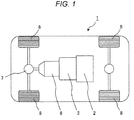
- FIG. 1 is an example of a block diagram of a hybrid electric vehicle equipped with a rotary electric machine according to the present invention.
- a vehicle 1 of a hybrid electric vehicle is equipped with an engine 2 and a rotary electric machine 3 as a power source of a vehicle drive system.
- a rotation torque of the engine 2 and the rotary electric machine 3 is transmitted to wheels (driving wheels) 8 via a transmission 6 (for example, a stepless transmission or a stepped transmission) and a differential gear 7.
- the rotary electric machine 3 is generally mounted between the engine 2 and the transmission 6 or in the transmission 6. Therefore, the rotary electric machine 3 is required to be miniaturized and have high output in order to minimize space occupation in the vehicle 1 and increase a driving force.
- a plurality of rotary electric machines may be incorporated in the drive system.
- two rotary electric machines having different roles may be incorporated, and one rotary electric machine may be responsible for both power generation and vehicle drive, and the other rotary electric machine may be responsible for only vehicle drive.
- FIG. 2 is a partial schematic vertical cross-sectional view illustrating an example of a rotary electric machine according to the present invention.
- a vertical cross section of the rotary electric machine is defined as a cross section in a rotation axis direction (a cross section in which a normal line is orthogonal to the rotation axis) .
- the rotary electric machine 3 has a structure in which a stator 33 is generally fixed to an outer peripheral side in a housing 31 by a fixing mechanism 32 (for example, a bolt), a rotor 37 is disposed inside the stator 33 in a radial direction, and a rotation shaft 38 disposed at a center of the rotor 37 is supported by the housing 31 via a bearing 39.
- the stator 33 includes a cylindrical stator core 351 and a stator coil 331 wound around the stator core 351.
- the stator coil 331 is a general term for a plurality of coils wound such that polarities are alternately different from each other in a rotation direction.
- a region protruding in an axial direction from the stator core 351 is referred to as an end portion 332.
- the housing 31 of the rotary electric machine 3 does not have to be separate from the housing of the engine 2 and the housing of the transmission 6.
- the housing 31 may be shared as the housing of the engine 2 or as the housing of the transmission 6.
- the housing 31 may be shared as the housing of the transmission 6.
- the configuration of the rotor is not particularly limited, and a known rotor (for example, a permanent magnet type rotor including a permanent magnet, a winding type rotor including a field winding, a squirrel-cage rotor including a squirrel-cage conductor in which opposite ends of a conductor wire of the rotor are short-circuited, and a reluctance type rotor configured of only a ferromagnetic core and not including a permanent magnet) can be appropriately used.
- a known rotor for example, a permanent magnet type rotor including a permanent magnet, a winding type rotor including a field winding, a squirrel-cage rotor including a squirrel-cage conductor in which opposite ends of a conductor wire of the rotor are short-circuited, and a reluctance type rotor configured of only a ferromagnetic core and not including a permanent magnet
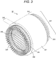
- FIG. 3 is a schematic perspective view illustrating an example of a stator of a rotary electric machine according to the present invention
- FIG. 4 is an enlarged schematic transverse cross-sectional view of a slot region of a stator.
- a transverse cross section is defined as a cross section orthogonal to the axial direction (a cross section in which a normal line is parallel to the axial direction).
- the stator coil 331 is wound around a plurality of stator slots 352 (simply referred to as a slot) formed on an inner circumferential side of the stator core 351.
- the stator slot 352 is arranged and formed at a predetermined pitch in a circumferential direction of the stator core 351, and the stator slot 352 is a space formed penetrating in the axial direction, and a slit 353 extending in the axial direction is opened in an innermost circumferential portion.
- teeth 354 The portion of the stator core 351 that defines a shape of the stator slot 352 is referred to as teeth 354.
- the stator coil 331 is formed by bonding a plurality of segment conductors 333 by welding, and a welding portion 334 of the segment conductors 333 is generally formed collectively in a region of one end portion 332.
- the other end portion 332 of the stator coil 331 is usually a U-turn portion of each segment conductor 333.
- Opposite end portions 332 are generally twisted in order to minimize an axial length of the stator coil 331 (see FIG. 3 ).
- a plurality of segment conductors 333 are arranged in each stator slot 352.
- three segment conductors 333 corresponding to U-phase, V-phase and W-phase of three-phase AC are arranged.
- an outer periphery of each segment conductor 333 is covered by an electric insulating material 361 (for example, an insulating paper) in an entire axial direction of the stator slot 352.
- the number of segment conductors 333 arranged in each stator slot 352 is not limited to "three" as shown in FIGS. 3 to 4 , but the number thereof may be appropriately set based on a design of the rotary electric machine 3.
- a winding form of the stator coil 331 (a bonding configuration of a plurality of segment conductors 333) is not particularly limited, and the winding form thereof is appropriately set based on a design of the rotary electric machine 3.
- the number of segment conductors 333 of each phase (U phase, V phase, and W phase) is not limited to "one" as shown in FIG. 4 , and the number thereof may be divided plurally.
- an insulated wire (so-called enameled wire), on which an electrical insulating coating formed of a resin material (for example, polyamide imide, polyimide, polyether ether ketone) is formed, is appropriately used for an outer periphery of the conductor wire formed of well electrically conductive metal (for example, oxygen-free copper, tough pitch copper, aluminum, aluminum alloy).
- a cross-sectional shape of the conductor wire and the insulated wire is not particularly limited, but from the viewpoint of a conductor space factor in the coil, it is preferable to use the conductor wire and the insulated wire having a rectangular cross-sectional shape.
- an exposed conductor wire portion of a pair of the segment conductors 333 configuring a welding portion 334 of the stator coil 331 includes, in a longitudinal direction of the conductor wire, a root portion adjacent to the insulating coating, a transition portion for offsetting a center axis of the conductor wire in a radial direction by a predetermined amount of displacement, and a bonding portion offset in the radial direction with respect to the root portion by the predetermined amount of displacement, and there is a feature that a boundary portion between the root portion and the transition portion and a boundary portion between the transition portion and the bonding portion have pressing marks.
- the feature will be described in detail in a method for manufacturing a stator as follows.
- FIG. 5 is a flow chart illustrating an example of steps in a method for manufacturing a stator of a rotary electric machine according to the present invention.
- the method for manufacturing a stator of a rotary electric machine according to the present invention generally, includes an insulating strand preparation step (S1) of preparing an insulating strand 344 of which opposite ends include an exposed conductor wire portion 343, a segment strand preparation step (S2) of preparing a segment strand 345 by performing a press forming work on the exposed conductor wire portion 343 of the prepared insulating strand 344, a segment conductor preparation step (S3) of preparing a segment conductor 333 by performing a U-shape forming work on the prepared segment strand 345, a segment conductor insertion and twist step (S4) of inserting the prepared segment conductor 333 into a slot 352 of a stator core 351 and performing a twisting work on
- S1 of preparing an insulating strand 344 of which opposite ends include an exposed conduct
- Step S1 is a step of preparing an insulating strand 344 including an exposed conductor wire portion 343 by removing an insulating coating 342 in a region of opposite ends of an insulated wire, the insulated wire including the insulating coating 342 formed on an outer periphery of a conductor wire 341 and having a predetermined length.
- a method for removing the insulating coating 342 is not particularly limited, and a known method may be appropriately used.
- an insulated wire having a cross-sectional area of the conductor wire 341 and a thickness of the insulating coating 342 suitable for the design of the rotary electric machine 3 (for example, a current and voltage of the stator coil 331) is selected.
- the voltage and current of the stator coil are increased, and in the insulated wire to be used, the cross-sectional area of the conductor wire 341 and the thickness of the insulating coating 342 are increased.
- the thickness of the insulating coating 342 has been about 15 ⁇ m to 45 ⁇ m in the past, but in recent years, it is 50 ⁇ m or more, or 100 ⁇ m or more.
- Step S2 is a step of preparing a segment strand 345 by performing a press forming work on an exposed conductor wire portion 343 of the insulating strand 344 prepared in step S1. More specifically, step S2 is a step of, in a longitudinal direction of an exposed conductor wire portion 343, performing a press forming work on a root portion 343b adjacent to the insulating coating 342, a transition portion 343t for offsetting a center axis of the conductor wire 341 by a predetermined amount of displacement, and a bonding portion 343j offset with respect to the root portion 343b by a predetermined amount of displacement.
- FIG. 6 is a schematic view illustrating an example of a press forming work in a segment strand preparation step.
- the insulating strand 344 and a press dies 401 and 402 are disposed such that the press dies 401 and 402 do not sandwich the insulating coating 342 of the insulating strand 344.
- a root end of the exposed conductor wire portion 343 of the insulating strand 344 (a tip of the insulating coating 342) and ends of root regions 401b and 402b of the press dies 401 and 402 are disposed so as not to overlap with another. This is for preventing electric insulation from decreasing due to the crushing of the insulating coating 342.
- a root portion 343b, a transition portion 343t and a bonding portion 343j are formed in the exposed conductor wire portion 343.
- pressing marks caused by the press dies 401 and 402 remain at a boundary portion between the root portion 343b and the transition portion 343t and a boundary portion between the transition portion 343t and the bonding portion 343j.
- a displacement amount x to be offset (a displacement amount x between the root portion 343b and the bonding portion 343j) is preferably "1 ⁇ 0.4" times the thickness of the insulating coating 342 (that is, 0.6 to 1.4 times), and more preferably “1 ⁇ 0.2" times the thickness of the insulating coating 342 (that is, 0.8 to 1.2 times).
- step S2 is performed on the exposed conductor wire portion 343 at opposite ends of the insulating strand 344.
- a length of the root portion 343b and a length of the transition portion 343t are respectively shorter than a length of the bonding portion 343j.
- the length of the root portion 343b, the transition portion 343t, and the bonding portion 343j means a length of the conductor wire 341 in the longitudinal direction (a length in the right and left direction of the conductor wire 341 in FIG. 6 ).
- the length of the transition portion 343t is 0.5 times or more and 2 times or less the thickness of the conductor wire 341 (in FIG. 6 , a vertical direction of the conductor wire 341).
- Step S3 is a step of preparing a segment conductor 333 by performing a U-shape forming work on the segment strand 345 prepared in step S2.
- a method of the U-shaped forming work is not particularly limited, and a known method may be appropriately used.
- Step S4 is a step of inserting the segment conductor 333 prepared in step S3 into a slot 352 of a stator core 351 and performing a twisting work on a region which is an end portion 332 of a stator coil 331.
- the segment conductor 333 is inserted into the slot 352, it is preferable to insert an electric insulating material 361 with the segment conductor 333.
- a method for inserting the segment conductor 333 and the electric insulating material 361 into the slot 352 and the method for performing the twisting work on the region which is the end portion 332, are not particularly limited, and a known method may be appropriately used.
- Step S5 is a step of forming a welding portion 334 of the stator coil 331 by welding the bonding portions 343j of the segment conductor 333 twisted in step S4.
- FIG. 7 is a schematic view illustrating an example of a welding method in a segment conductor welding step. As shown in FIG. 7 , the bonding portions 343j of the segment conductor 333 are welded by an arc welder 500.
- step S5 it is a very important object to suppress a heat damage to the insulating coating 342 of the segment conductor 333 in the vicinity of the welding portion 334. In order to suppress the heat damage to the insulating coating 342, it is desirable to reduce the heat input amount for welding.
- a welding method is not limited to the arc welding, and other known welding (for example, an electron beam welding, a laser welding, and a plasma welding) can be appropriately used.
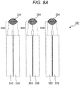
- FIG. 8A is an enlarged schematic view in a circumferential direction illustrating an example of a welding portion of a stator coil in a first embodiment
- FIG. 8B is an enlarged schematic view in a circumferential direction illustrating an example of a welding portion of a stator coil in the related art.
- the bonding portions 343j are easily aligned with each other (are abutted to each other) in the welding step since the exposed conductor wire portion 343 of each segment conductor 333 includes the root portion 343b, the transition portion 343t, and the bonding portion 343j, and the bonding portion 343j is offset with respect to the root portion 343b in the radial direction by a displacement amount of "1 ⁇ 0.4" times the thickness of the insulating coating 342.
- the fact that the bonding portion 343j offset with respect to the root portion 343b is subjected to a forming work in advance means that there is substantially not an internal stress in a direction in which the welding portion 334 is peeled off between a pair of the segment conductors 333 forming the welding portion 334, and it has an effect of suppressing welding defects due to a misalignment during welding and welding peeling off after welding. These effects bring about an improvement of the manufacturability of the stator 33, an improvement of the manufacturing yield, and an improvement of the reliability, which leads to a reduction of the manufacturing cost.
- the entire exposed conductor wire portion 343 is gently displaced in the radial direction.
- a contact area between the exposed conductor wire portions 343 depends greatly on a gripping force of the bonding portion grip jig 502 in the welding step (a compression force abutting the exposed conductor wire portions 343 of a pair of the segment conductor) and a rigidity of the conductor wire 341.
- a rigidity of the conductor wire 341 is high and a reaction force to the gripping force of the bonding portion grip jig 502 (a force resisting the force abutting the exposed conductor wire portions 343) is great. Therefore, a contact area of the exposed conductor wire portions 343 tends to be small. This hinders the formation of the welding portion 334 having a sufficiently large size and causes the welding peeling off after welding.
- the welding portion 334 having a sufficiently large size and the welding peeling off after welding cause the manufacturing yield and the reliability to decrease, which leads to an increase in the manufacturing cost.
- a stator of the rotary electric machine and the method for manufacturing the stator thereof according to the present invention are very effective techniques for the stator coil in which the cross-sectional area of the conductor wire 341 and the thickness of the insulating coating 342 are increased.
- This step is a step of insulating each exposed conductor wire portion 343 including the welding portion 334 welded in step S5.
- a method of insulation treatment is not particularly limited, and a known method may be appropriately used. This step is not an essential step and is performed based on a design of the rotary electric machine 3.
- the second embodiment is different from the first embodiment only in the shape of the exposed conductor wire portion forming the welding portion of the stator coil, but other configurations are the same. Therefore, only the shape of the welding portion and the exposed conductor wire portion will be described.
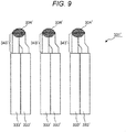
- FIG. 9 is an enlarged schematic view in a circumferential direction illustrating an example of a welding portion of a stator coil in a second embodiment.
- an exposed conductor wire portion 343' on only one side of a pair of segment conductors 333' forming a welding portion 334' includes a root portion 343b, a transition portion 343t, and a bonding portion 343j, and the bonding portion 343j is offset with respect to the root portion 343b in the radial direction by a displacement amount x of "2 ⁇ 0.4" times the thickness of the insulating coating 342.
- the offset displacement amount x is more preferably "2 ⁇ 0.2" times.
- This embodiment is an effective technique when the thickness of the insulating coating 342 is 50 ⁇ m or more. Further, in the embodiment, in addition to the same effect as that of the first embodiment, a work amount of the press forming wok in the segment strand preparation step S2 is half of the work amount in the first embodiment. Therefore, it has an effect that the manufacturing cost can be further reduced.
Landscapes
- Engineering & Computer Science (AREA)
- Power Engineering (AREA)
- Manufacturing & Machinery (AREA)
- Manufacture Of Motors, Generators (AREA)
- Windings For Motors And Generators (AREA)
Abstract
Description
- The present invention relates to a rotary electric machine, and more particularly to a stator that contributes to miniaturization and high output of a rotary electric machine, and a rotary electric machine including the stator.
- An example of a rotary electric machine (for example, a motor) includes a field winding-type rotary electric machine. The field winding-type rotary electric machine has a mechanism in which a stator coil is arranged in a plurality of stator slots formed in a stator core, and when a voltage is applied to the stator coil, a rotating magnetic field is generated, and a rotor is rotated by the rotating magnetic field.
- In recent years, there has been a strong demand for miniaturization of the rotary electric machine (particularly, reducing a length in a rotation axis direction), and in order to meet the demand, a winding form of the stator coil has become complicated. Further, although there is a strong demand for cost reduction in the rotary electric machine, a manufacturing yield tends to decrease due to the complicated winding form of the stator coil, and there has been an object of improving manufacturability of the stator. For example, in a step of welding segment conductors in an end portion of the stator coil, there has been a problem in that an insulating coating of the segment conductors may be thermally damaged, and as a result, an electric insulation between the segment conductors to be electrically insulated is reduced.
- Various techniques have been researched and developed to achieve the object. For example, PTL 1 (
JP 2009-081980 A - PTL 2 (
JP 2014-107876 A -
- PTL 1:
JP 2009-081980 A - PTL 2:
JP 2014-107876 A - According to
PTL 1, in the stator of a rotary electric machine, the coil segments can be reliably bonded to each other while maintaining a sufficient insulation interval except the bonding portion of the coil segment, and high-quality bonding without a short circuit can be achieved. According toPTL 2, it is possible to provide a method for manufacturing a stator in which heat effect generated at the time of welding a coil end portion can be suppressed, and a damage to the insulating coating of the segment can be suppressed without extending an axial length of a conductor segment. - On the other hand, a recent rotary electric machine is strongly required to have high output in addition to the above-mentioned miniaturization thereof, and the applied voltage is being increased in order to correspond to the high output. The increasing of the applied voltage means applying a large current to the segment conductor, and it is necessary to increase a cross-sectional area of the conductor and a thickness of the insulating coating. As a result, flexibility of the segment conductor is decreased more than before and heat capacity is increased more than before, and therefore, only with a simple combination of the related arts, manufacturability of the stator tends to be decreased, which is a big problem. In other words, in order to improve the manufacturability of the stator (that is, to meet the demand for cost reduction) in the rotary electric machine corresponding to the miniaturization and the high output, a new effort has been required.
- In view of the above circumstances, an object of the present invention is to provide a stator of a rotary electric machine of which miniaturization, high output, and cost reduction are balanced at a higher level than the related art, and a rotary electric machine including the stator.
-
- (I) According to an aspect of the present invention, there is provided a stator of a rotary electric machine in which a stator coil is wound around a stator core. The stator coil includes a welding portion of segment conductors formed in a region of an end portion of the stator coil; each of the segment conductors includes an exposed conductor wire portion in which an insulating coating formed on an outer periphery of a conductor wire is removed in a vicinity of the welding portion; the exposed conductor wire portion on at least one side of a pair of the segment conductors forming the each welding portion includes, in a longitudinal direction of the conductor wire, a root portion adjacent to the insulating coating, a transition portion for offsetting a center axis of the conductor wire in a radial direction by a predetermined amount of displacement, and a bonding portion offset in the radial direction with respect to the root portion by the predetermined amount of displacement, and a boundary portion between the root portion and the transition portion and a boundary portion between the transition portion and the bonding portion have pressing marks; and the predetermined amount of displacement is "1 ± 0.4" times or "2 ± 0.4" times a thickness of the insulating coating.
The present invention can make the following improvements and modifications to the stator of a rotary electric machine (I) described above.- (i) A length of the root portion and a length of the transition portion are respectively shorter than a length of the bonding portion.
- (ii) Opposite sides of a pair of the exposed conductor wire portions forming the welding portion include the transition portion, and the predetermined amount of displacement is "1 ± 0.4" times the thickness of the insulating coating.
- (iii) Only one side of a pair of the exposed conductor wire portions forming the welding portion includes the transition portion, and the predetermined amount of displacement is "2 ± 0.4" times the thickness of the insulating coating.
- (iv) The welding portion has an overlay welding structure including a welding metal formed of an alloy of the conductor wire and a welding material having a melting point lower than that of the conductor wire.
- (v) The conductor wire is formed of oxygen-free copper or tough pitch copper.
- (vi) The conductor wire is formed of aluminum or an aluminum alloy.
- (II) According to another aspect of the present invention, there is provided a method for manufacturing a stator of a rotary electric machine. The method includes: an insulating strand preparation step of preparing an insulating strand including the exposed conductor wire portion by removing the insulating coating in a region of an opposite ends of an insulated wire, the insulated wire including the insulating coating formed on an outer periphery of the conductor wire and having a predetermined length; a segment strand preparation step of preparing a segment strand, of which the exposed conductor wire portion includes the root portion, the transition portion and bonding portion, by performing a press forming work on the exposed conductor wire portion of the prepared insulating strand; a segment conductor preparation step of preparing the segment conductor by performing a U-shape forming work on the prepared segment strand; a segment conductor insertion and twist step of inserting the prepared segment conductor into a slot of the stator core and performing a twisting work on a region which is the end portion of the stator coil; and a segment conductor welding step of welding the bonding portions of the segment conductor to form a welding portion of the stator coil.
- (III) According to still another aspect of the present invention, there is provided a rotary electric machine including a stator, in which the stator is the above described stator of a rotary electric machine.
- (IV) According to still another aspect of the present invention, there is provided a stator of a rotary electric machine in which a stator coil is wound around a stator core. The stator coil includes a welding portion of segment conductors formed in a region of an end portion of the stator coil; each of the segment conductors includes an exposed conductor wire portion in which an insulating coating formed on an outer periphery of a conductor wire is removed in a vicinity of the welding portion; the exposed conductor wire portion on at least one side of a pair of the segment conductors forming the each welding portion includes, in a longitudinal direction of the conductor wire, a root portion adjacent to the insulating coating, a transition portion for offsetting a center axis of the conductor wire in the radial direction by a predetermined amount of displacement, and a bonding portion offset in the radial direction with respect to the root portion by the predetermined amount of displacement, and a boundary portion between the root portion and the transition portion and a boundary portion between the transition portion and the bonding portion have pressing marks; and a length of the root portion and a length of the transition portion are respectively shorter than a length of the bonding portion.
- According to the present invention, the stator of a rotary electric machine, of which miniaturization, high output, and cost reduction are balanced at a higher level than the related art, can be provided.
- The rotary electric machine, of which miniaturization, high output, and cost reduction are balanced at a higher level than the related art by using the stator, can be provided.
-
- [
FIG. 1] FIG. 1 is an example of a block diagram of a hybrid electric vehicle equipped with a rotary electric machine according to the present invention. - [
FIG. 2] FIG. 2 is a partial schematic vertical cross-sectional view illustrating an example of a rotary electric machine according to the present invention. - [
FIG. 3] FIG. 3 is a schematic perspective view illustrating an example of a stator of a rotary electric machine according to the present invention. - [
FIG. 4] FIG. 4 is an enlarged schematic cross-sectional view of a slot region of a stator. - [
FIG. 5] FIG. 5 is a flow chart illustrating an example of steps in a method for manufacturing a stator of a rotary electric machine according to the present invention. - [
FIG. 6] FIG. 6 is a schematic view illustrating an example of a press forming work in a segment strand preparation step. - [
FIG. 7] FIG. 7 is a schematic view illustrating an example of a welding method in a segment conductor welding step. - [
FIG. 8A] FIG. 8A is an enlarged schematic view in a circumferential direction illustrating an example of a welding portion of a stator coil in a first embodiment. - [
FIG. 8B] FIG. 8B is an enlarged schematic view in a circumferential direction illustrating an example of a welding portion of a stator coil in the related art. - [
FIG. 9] FIG. 9 is an enlarged schematic view in a circumferential direction illustrating an example of a welding portion of a stator coil in a second embodiment. - The present invention is not limited to the embodiments described in the present specification, and can be appropriately modified by a combination with a known technique or based on the known technique within a range not departing from the technical idea of the invention. Members having the same meaning are denoted by the same reference numerals, and overlapping descriptions will be omitted
- Hereinafter, in the embodiments according to the present invention, an example of a rotary electric machine for a hybrid electric vehicle will be specifically described with reference to the drawings. In the present specification, an "axial direction" indicates a direction along a rotation axis of a rotary electric machine, a "circumferential direction" indicates a direction along a rotation direction of a rotary electric machine, and a "radial direction" indicates a radial direction when a rotation axis of the rotary electric machine is set to be a center.
-
FIG. 1 is an example of a block diagram of a hybrid electric vehicle equipped with a rotary electric machine according to the present invention. As shown inFIG. 1 , avehicle 1 of a hybrid electric vehicle is equipped with anengine 2 and a rotaryelectric machine 3 as a power source of a vehicle drive system. A rotation torque of theengine 2 and the rotaryelectric machine 3 is transmitted to wheels (driving wheels) 8 via a transmission 6 (for example, a stepless transmission or a stepped transmission) and adifferential gear 7. The rotaryelectric machine 3 is generally mounted between theengine 2 and the transmission 6 or in the transmission 6. Therefore, the rotaryelectric machine 3 is required to be miniaturized and have high output in order to minimize space occupation in thevehicle 1 and increase a driving force. - Although not shown in
FIG. 1 , a plurality of rotary electric machines may be incorporated in the drive system. For example, two rotary electric machines having different roles may be incorporated, and one rotary electric machine may be responsible for both power generation and vehicle drive, and the other rotary electric machine may be responsible for only vehicle drive. -
FIG. 2 is a partial schematic vertical cross-sectional view illustrating an example of a rotary electric machine according to the present invention. A vertical cross section of the rotary electric machine is defined as a cross section in a rotation axis direction (a cross section in which a normal line is orthogonal to the rotation axis) . As shown inFIG. 2 , the rotaryelectric machine 3 has a structure in which astator 33 is generally fixed to an outer peripheral side in ahousing 31 by a fixing mechanism 32 (for example, a bolt), arotor 37 is disposed inside thestator 33 in a radial direction, and arotation shaft 38 disposed at a center of therotor 37 is supported by thehousing 31 via abearing 39. - The
stator 33 includes acylindrical stator core 351 and astator coil 331 wound around thestator core 351. Thestator coil 331 is a general term for a plurality of coils wound such that polarities are alternately different from each other in a rotation direction. In thestator coil 331, a region protruding in an axial direction from thestator core 351 is referred to as anend portion 332. When a three-phase AC voltage (for example, 400 V to 800 V) is applied to thestator coil 331 to apply a large current (for example, 200 A to 400 A), a rotating magnetic field is generated, and a rotaryelectric machine 3 is operated as a motor. - The
housing 31 of the rotaryelectric machine 3 does not have to be separate from the housing of theengine 2 and the housing of the transmission 6. For example, as shown inFIG. 1 , when the rotaryelectric machine 3 is arranged between theengine 2 and the transmission 6, thehousing 31 may be shared as the housing of theengine 2 or as the housing of the transmission 6. When the rotaryelectric machine 3 is mounted in the transmission 6, thehousing 31 may be shared as the housing of the transmission 6. - In the rotary electric machine according to the present invention, the configuration of the rotor is not particularly limited, and a known rotor (for example, a permanent magnet type rotor including a permanent magnet, a winding type rotor including a field winding, a squirrel-cage rotor including a squirrel-cage conductor in which opposite ends of a conductor wire of the rotor are short-circuited, and a reluctance type rotor configured of only a ferromagnetic core and not including a permanent magnet) can be appropriately used.
-
FIG. 3 is a schematic perspective view illustrating an example of a stator of a rotary electric machine according to the present invention, andFIG. 4 is an enlarged schematic transverse cross-sectional view of a slot region of a stator. A transverse cross section is defined as a cross section orthogonal to the axial direction (a cross section in which a normal line is parallel to the axial direction). - As shown in
FIGS. 3 to 4 , in thestator 33, thestator coil 331 is wound around a plurality of stator slots 352 (simply referred to as a slot) formed on an inner circumferential side of thestator core 351. Thestator slot 352 is arranged and formed at a predetermined pitch in a circumferential direction of thestator core 351, and thestator slot 352 is a space formed penetrating in the axial direction, and aslit 353 extending in the axial direction is opened in an innermost circumferential portion. - The portion of the
stator core 351 that defines a shape of thestator slot 352 is referred to asteeth 354. - The
stator coil 331 is formed by bonding a plurality ofsegment conductors 333 by welding, and awelding portion 334 of thesegment conductors 333 is generally formed collectively in a region of oneend portion 332. Theother end portion 332 of thestator coil 331 is usually a U-turn portion of eachsegment conductor 333. Oppositeend portions 332 are generally twisted in order to minimize an axial length of the stator coil 331 (seeFIG. 3 ). - A plurality of
segment conductors 333 are arranged in eachstator slot 352. For example, inFIG. 4 , threesegment conductors 333 corresponding to U-phase, V-phase and W-phase of three-phase AC are arranged. Further, from the viewpoint of preventing partial discharge between thesegment conductor 333 and thestator core 351 and partial discharge between each phase (U phase, V phase, and W phase), it is preferable that an outer periphery of eachsegment conductor 333 is covered by an electric insulating material 361 (for example, an insulating paper) in an entire axial direction of thestator slot 352. - In the present invention, the number of
segment conductors 333 arranged in eachstator slot 352 is not limited to "three" as shown inFIGS. 3 to 4 , but the number thereof may be appropriately set based on a design of the rotaryelectric machine 3. In other words, a winding form of the stator coil 331 (a bonding configuration of a plurality of segment conductors 333) is not particularly limited, and the winding form thereof is appropriately set based on a design of the rotaryelectric machine 3. The number ofsegment conductors 333 of each phase (U phase, V phase, and W phase) is not limited to "one" as shown inFIG. 4 , and the number thereof may be divided plurally. - As the
segment conductor 333, an insulated wire (so-called enameled wire), on which an electrical insulating coating formed of a resin material (for example, polyamide imide, polyimide, polyether ether ketone) is formed, is appropriately used for an outer periphery of the conductor wire formed of well electrically conductive metal (for example, oxygen-free copper, tough pitch copper, aluminum, aluminum alloy). A cross-sectional shape of the conductor wire and the insulated wire is not particularly limited, but from the viewpoint of a conductor space factor in the coil, it is preferable to use the conductor wire and the insulated wire having a rectangular cross-sectional shape. - In the
stator 33 of the present invention, an exposed conductor wire portion of a pair of thesegment conductors 333 configuring awelding portion 334 of the stator coil 331 (a region in which the insulating coating formed on the outer periphery of the conductor wire is removed) includes, in a longitudinal direction of the conductor wire, a root portion adjacent to the insulating coating, a transition portion for offsetting a center axis of the conductor wire in a radial direction by a predetermined amount of displacement, and a bonding portion offset in the radial direction with respect to the root portion by the predetermined amount of displacement, and there is a feature that a boundary portion between the root portion and the transition portion and a boundary portion between the transition portion and the bonding portion have pressing marks. The feature will be described in detail in a method for manufacturing a stator as follows. - A method for manufacturing a stator according to the present invention will be described.
FIG. 5 is a flow chart illustrating an example of steps in a method for manufacturing a stator of a rotary electric machine according to the present invention. As shown inFIG. 5 , the method for manufacturing a stator of a rotary electric machine according to the present invention, generally, includes an insulating strand preparation step (S1) of preparing an insulatingstrand 344 of which opposite ends include an exposedconductor wire portion 343, a segment strand preparation step (S2) of preparing asegment strand 345 by performing a press forming work on the exposedconductor wire portion 343 of the prepared insulatingstrand 344, a segment conductor preparation step (S3) of preparing asegment conductor 333 by performing a U-shape forming work on theprepared segment strand 345, a segment conductor insertion and twist step (S4) of inserting theprepared segment conductor 333 into aslot 352 of astator core 351 and performing a twisting work on a region which is anend portion 332 of a stator coil, and a segment conductor welding step (S5) of welding bonding portions of thesegment conductor 333 to form awelding portion 334 of the stator coil. - Hereinafter, each step will be described in detail.
- Step S1 is a step of preparing an insulating
strand 344 including an exposedconductor wire portion 343 by removing an insulatingcoating 342 in a region of opposite ends of an insulated wire, the insulated wire including the insulatingcoating 342 formed on an outer periphery of aconductor wire 341 and having a predetermined length. A method for removing the insulatingcoating 342 is not particularly limited, and a known method may be appropriately used. - As the insulated wire to be used, an insulated wire having a cross-sectional area of the
conductor wire 341 and a thickness of the insulatingcoating 342 suitable for the design of the rotary electric machine 3 (for example, a current and voltage of the stator coil 331) is selected. In recent years, due to a demand for miniaturization and high output of a rotary electric machine, the voltage and current of the stator coil are increased, and in the insulated wire to be used, the cross-sectional area of theconductor wire 341 and the thickness of the insulatingcoating 342 are increased. For example, the thickness of the insulatingcoating 342 has been about 15 µm to 45 µm in the past, but in recent years, it is 50 µm or more, or 100 µm or more. - Step S2 is a step of preparing a
segment strand 345 by performing a press forming work on an exposedconductor wire portion 343 of the insulatingstrand 344 prepared in step S1. More specifically, step S2 is a step of, in a longitudinal direction of an exposedconductor wire portion 343, performing a press forming work on aroot portion 343b adjacent to the insulatingcoating 342, atransition portion 343t for offsetting a center axis of theconductor wire 341 by a predetermined amount of displacement, and abonding portion 343j offset with respect to theroot portion 343b by a predetermined amount of displacement. -
FIG. 6 is a schematic view illustrating an example of a press forming work in a segment strand preparation step. As shown inFIG. 6(a) , first, at the time of the press forming work, the insulatingstrand 344 and a press dies 401 and 402 are disposed such that the press dies 401 and 402 do not sandwich the insulatingcoating 342 of the insulatingstrand 344. In other words, a root end of the exposedconductor wire portion 343 of the insulating strand 344 (a tip of the insulating coating 342) and ends ofroot regions coating 342. - When a load is applied to the exposed
conductor wire portion 343 by the press dies 401 and 402 and then the load is released, as shown inFIG. 6(b) , aroot portion 343b, atransition portion 343t and abonding portion 343j are formed in the exposedconductor wire portion 343. At this time, pressing marks caused by the press dies 401 and 402 remain at a boundary portion between theroot portion 343b and thetransition portion 343t and a boundary portion between thetransition portion 343t and thebonding portion 343j. - When a thickness of the insulating
coating 342 is 100 µm or more, a displacement amount x to be offset (a displacement amount x between theroot portion 343b and thebonding portion 343j) is preferably "1 ± 0.4" times the thickness of the insulating coating 342 (that is, 0.6 to 1.4 times), and more preferably "1 ± 0.2" times the thickness of the insulating coating 342 (that is, 0.8 to 1.2 times). When the offset displacement amount x is "1 ± 0.4" times the thickness of the insulatingcoating 342, step S2 is performed on the exposedconductor wire portion 343 at opposite ends of the insulatingstrand 344. When the displacement amount deviates from the regulation, the sufficient effect in the segment conductor welding step which will be described later cannot be obtained. - From the viewpoint of reducing an axial length of the
end portion 332 of thestator coil 331, it is preferable that a length of theroot portion 343b and a length of thetransition portion 343t are respectively shorter than a length of thebonding portion 343j. Here, "the length of theroot portion 343b, thetransition portion 343t, and thebonding portion 343j" means a length of theconductor wire 341 in the longitudinal direction (a length in the right and left direction of theconductor wire 341 inFIG. 6 ). When the length of theroot portion 343b and the length of thebonding portion 343j on one surface of the exposed conductor wire portion 343 (for example, the surface on the press die 401 side inFIG. 6 ) do not match with the length of theroot portion 343b and the length of thebonding portion 343j on the other surface of the exposed conductor wire portion 343 (for example, the surface on the press die 402 side inFIG. 6 ), it is preferable to compare the longer portion of theroot portion 343b with the shorter portion of thebonding portion 343j. - From the viewpoint of securing the displacement amount x at the
transition portion 343t (in other words, stabilizing plastic deformation in thetransition portion 343t), it is preferable that the length of thetransition portion 343t is 0.5 times or more and 2 times or less the thickness of the conductor wire 341 (inFIG. 6 , a vertical direction of the conductor wire 341). - Step S3 is a step of preparing a
segment conductor 333 by performing a U-shape forming work on thesegment strand 345 prepared in step S2. A method of the U-shaped forming work is not particularly limited, and a known method may be appropriately used. - Step S4 is a step of inserting the
segment conductor 333 prepared in step S3 into aslot 352 of astator core 351 and performing a twisting work on a region which is anend portion 332 of astator coil 331. When thesegment conductor 333 is inserted into theslot 352, it is preferable to insert an electricinsulating material 361 with thesegment conductor 333. A method for inserting thesegment conductor 333 and the electric insulatingmaterial 361 into theslot 352 and the method for performing the twisting work on the region which is theend portion 332, are not particularly limited, and a known method may be appropriately used. - Step S5 is a step of forming a
welding portion 334 of thestator coil 331 by welding thebonding portions 343j of thesegment conductor 333 twisted in step S4.FIG. 7 is a schematic view illustrating an example of a welding method in a segment conductor welding step. As shown inFIG. 7 , thebonding portions 343j of thesegment conductor 333 are welded by anarc welder 500. More specifically, after a bondingportion grip jig 502 connected to awelding power source 501 grips thebonding portions 343j of thesegment conductor 333, an arc is generated between anelectrode 503 and thebonding portion 343j by applying a voltage between theelectrode 503 connected to awelding power source 502 and the bondingportion grip jig 502, and thebonding portions 343j are welded to form awelding portion 334. - As described above, due to a demand for miniaturization and high output of a rotary electric machine, the cross-sectional area of the
conductor wire 341 are increased. This means that heat capacity of the welded portion is increased more than before and a heat input amount for welding is required more than before. However, in step S5, it is a very important object to suppress a heat damage to the insulatingcoating 342 of thesegment conductor 333 in the vicinity of thewelding portion 334. In order to suppress the heat damage to the insulatingcoating 342, it is desirable to reduce the heat input amount for welding. - In order to achieve both of these contrary matters, at the time of welding, it is more preferable to perform overlay welding while supplying a
welding material 505 having a melting point lower than that of the material of theconductor wire 341 by operating a bondingmaterial supply device 504 at the same time. By performing the overlay welding, a sufficient amount of thewelding material 505 having a melting point lower than that of the material of theconductor wire 341 can be supplied, and as a result, an alloy phase having a melting point lower than that of the material of theconductor wire 341 is generated on thewelding portion 334. This means that a heat amount required for welding can be reduced, which leads to a suppression of a heat damage to the insulatingcoating 342 in the vicinity of thebonding portion 334. - A welding method is not limited to the arc welding, and other known welding (for example, an electron beam welding, a laser welding, and a plasma welding) can be appropriately used.
-
FIG. 8A is an enlarged schematic view in a circumferential direction illustrating an example of a welding portion of a stator coil in a first embodiment, andFIG. 8B is an enlarged schematic view in a circumferential direction illustrating an example of a welding portion of a stator coil in the related art. - As shown in
FIG. 8A , in thewelding portion 334 of thestator coil 331 according to the first embodiment, there is an effect that thebonding portions 343j are easily aligned with each other (are abutted to each other) in the welding step since the exposedconductor wire portion 343 of eachsegment conductor 333 includes theroot portion 343b, thetransition portion 343t, and thebonding portion 343j, and thebonding portion 343j is offset with respect to theroot portion 343b in the radial direction by a displacement amount of "1 ± 0.4" times the thickness of the insulatingcoating 342. Further, the fact that thebonding portion 343j offset with respect to theroot portion 343b is subjected to a forming work in advance means that there is substantially not an internal stress in a direction in which thewelding portion 334 is peeled off between a pair of thesegment conductors 333 forming thewelding portion 334, and it has an effect of suppressing welding defects due to a misalignment during welding and welding peeling off after welding. These effects bring about an improvement of the manufacturability of thestator 33, an improvement of the manufacturing yield, and an improvement of the reliability, which leads to a reduction of the manufacturing cost. - Since an unnecessary compression stress is not applied between the insulating
coatings 342 of a pair of thesegment conductors 333, there is a secondary effect that deterioration of the electric insulation due to the crushing of the insulatingcoating 342 can be prevented. - On the other hand, as shown in
FIG. 8B , in thewelding portion 334 of the stator coil in the related art, in which the exposedconductor wire portion 343 is not subjected to the forming work in advance to include the root portion, transition portion, and the bonding portion, the entire exposedconductor wire portion 343 is gently displaced in the radial direction. A contact area between the exposedconductor wire portions 343 depends greatly on a gripping force of the bondingportion grip jig 502 in the welding step (a compression force abutting the exposedconductor wire portions 343 of a pair of the segment conductor) and a rigidity of theconductor wire 341. - In particular, in the segment conductor in which the cross-sectional area of the
conductor wire 341 and the thickness of the insulatingcoating 342 are increased, a rigidity of theconductor wire 341 is high and a reaction force to the gripping force of the bonding portion grip jig 502 (a force resisting the force abutting the exposed conductor wire portions 343) is great. Therefore, a contact area of the exposedconductor wire portions 343 tends to be small. This hinders the formation of thewelding portion 334 having a sufficiently large size and causes the welding peeling off after welding. Thewelding portion 334 having a sufficiently large size and the welding peeling off after welding cause the manufacturing yield and the reliability to decrease, which leads to an increase in the manufacturing cost. - When the gripping force of the bonding
portion grip jig 502 is made to be very large in order to increase the contact area between the exposedconductor wire portions 343, an excessive compression stress is applied between the insulatingcoatings 342 of a pair of the segment conductors. Therefore, it may cause electric insulation to decrease due to the crushing of the insulatingcoating 342. - As described above, a stator of the rotary electric machine and the method for manufacturing the stator thereof according to the present invention are very effective techniques for the stator coil in which the cross-sectional area of the
conductor wire 341 and the thickness of the insulatingcoating 342 are increased. - This step is a step of insulating each exposed
conductor wire portion 343 including thewelding portion 334 welded in step S5. A method of insulation treatment is not particularly limited, and a known method may be appropriately used. This step is not an essential step and is performed based on a design of the rotaryelectric machine 3. - The second embodiment is different from the first embodiment only in the shape of the exposed conductor wire portion forming the welding portion of the stator coil, but other configurations are the same. Therefore, only the shape of the welding portion and the exposed conductor wire portion will be described.
-
FIG. 9 is an enlarged schematic view in a circumferential direction illustrating an example of a welding portion of a stator coil in a second embodiment. As shown inFIG. 9 , in a welding portion 334' of a stator coil 331' according to the second embodiment, there is a feature that an exposedconductor wire portion 343' on only one side of a pair of segment conductors 333' forming a welding portion 334' includes aroot portion 343b, atransition portion 343t, and abonding portion 343j, and thebonding portion 343j is offset with respect to theroot portion 343b in the radial direction by a displacement amount x of "2 ± 0.4" times the thickness of the insulatingcoating 342. The offset displacement amount x is more preferably "2 ± 0.2" times. When the displacement amount deviates from the regulation, the sufficient effect in the segment conductor welding step cannot be obtained. - This embodiment is an effective technique when the thickness of the insulating
coating 342 is 50 µm or more. Further, in the embodiment, in addition to the same effect as that of the first embodiment, a work amount of the press forming wok in the segment strand preparation step S2 is half of the work amount in the first embodiment. Therefore, it has an effect that the manufacturing cost can be further reduced. - The above-described embodiments are described for the purpose of assisting the understanding of the present invention, and the present invention is not limited to the described specific configurations. For example, it is possible to replace a part of the configuration of the embodiment with a configuration of the common general technical knowledge of those skilled in the art, or to add the configuration of the common general technical knowledge of those skilled in the art to the configuration of the embodiment. That is, in the present invention, with respect to a part of the configuration of the embodiment in the present specification, it is possible to delete the part of the configuration, replace the part of the configuration with another configuration, or add another configuration to the part of the configuration without departing from the scope of the technical idea of the invention. Reference Signs List
-
- 1
- vehicle
- 2
- engine
- 3
- rotary electric machine
- 6
- transmission
- 7
- differential gear
- 8
- wheel
- 31
- housing
- 32
- fixing mechanism
- 33
- stator
- 37
- rotor
- 38
- rotation shaft
- 39
- bearing
- 331, 331'
- stator coil
- 332
- end portion
- 333, 333'
- segment conductor
- 334, 334'
- welding portion
- 341
- conductor wire
- 342
- insulating coating
- 343, 343'
- exposed conductor wire portion
- 343b
- root portion
- 343t
- transition portion
- 343j
- bonding portion
- 344
- insulating strand
- 345
- segment strand
- 351
- stator core
- 352
- stator slot
- 353
- slit
- 354
- teeth
- 401, 402
- press die
- 401b, 402b
- root region
- 500
- arc welder
- 501
- welding power source
- 502
- bonding portion grip jig
- 503
- electrode
- 504
- bonding material supply device
- 505
- welding material
Claims (10)
- A stator of a rotary electric machine in which a stator coil is wound around a stator core,
wherein the stator coil includes a welding portion of segment conductors formed in a region of an end portion of the stator coil,
each of the segment conductors includes an exposed conductor wire portion in which an insulating coating formed on an outer periphery of a conductor wire is removed in a vicinity of the welding portion,
the exposed conductor wire portion on at least one side of a pair of the segment conductors forming the each welding portion includes, in a longitudinal direction of the conductor wire, a root portion adjacent to the insulating coating, a transition portion for offsetting a center axis of the conductor wire in a radial direction by a predetermined amount of displacement, and a bonding portion offset in the radial direction with respect to the root portion by the predetermined amount of displacement, and a boundary portion between the root portion and the transition portion and a boundary portion between the transition portion and the bonding portion have pressing marks, and
the predetermined amount of displacement is "1 ± 0.4" times or "2 ± 0.4" times a thickness of the insulating coating. - The stator of a rotary electric machine according to claim 1, wherein a length of the root portion and a length of the transition portion are respectively shorter than a length of the bonding portion.
- The stator of a rotary electric machine according to claim 1 or 2, wherein
opposite sides of a pair of the exposed conductor wire portions forming the welding portion include the transition portion, and
the predetermined amount of displacement is "1 ± 0.4" times the thickness of the insulating coating. - The stator of a rotary electric machine according to claim 1 or 2, wherein
only one side of a pair of the exposed conductor wire portions forming the welding portion includes the transition portion, and
the predetermined amount of displacement is "2 ± 0.4" times the thickness of the insulating coating. - The stator of a rotary electric machine according to any one of claims 1 to 4, wherein the welding portion has an overlay welding structure including a welding metal formed of an alloy of the conductor wire and a welding material having a melting point lower than that of the conductor wire.
- The stator of a rotary electric machine according to any one of claims 1 to 5, wherein the conductor wire is formed of oxygen-free copper or tough pitch copper.
- The stator of a rotary electric machine according to any one of claims 1 to 5, wherein the conductor wire is formed of aluminum or an aluminum alloy.
- A method for manufacturing the stator of a rotary electric machine according to any one of claims 1 to 7, the method comprising:an insulating strand preparation step of preparing an insulating strand including the exposed conductor wire portion by removing the insulating coating in a region of opposite ends of an insulated wire, the insulated wire including the insulating coating formed on an outer periphery of the conductor wire and having a predetermined length;a segment strand preparation step of preparing a segment strand, of which the exposed conductor wire portion includes the root portion, the transition portion and bonding portion, by performing a press forming work on the exposed conductor wire portion of the prepared insulating strand;a segment conductor preparation step of preparing the segment conductor by performing a U-shape forming work on the prepared segment strand;a segment conductor insertion and twist step of inserting the prepared segment conductor into a slot of the stator core and performing a twisting work on a region which is the end portion of the stator coil; anda segment conductor welding step of welding the bonding portions of the segment conductor to form a welding portion of the stator coil.
- A rotary electric machine comprising a stator, wherein the stator is the stator of a rotary electric machine according to any one of claims 1 to 7.
- A stator of a rotary electric machine in which a stator coil is wound around a stator core, wherein
the stator coil includes a welding portion of segment conductors formed in a region of an end portion of the stator coil,
each of the segment conductors includes an exposed conductor wire portion in which an insulating coating formed on an outer periphery of a conductor wire is removed in a vicinity of the welding portion,
the exposed conductor wire portion on at least one side of a pair of the segment conductors forming the each welding portion includes, in a longitudinal direction of the conductor wire, a root portion adjacent to the insulating coating, a transition portion for offsetting a center axis of the conductor wire in a radial direction by a predetermined amount of displacement, and a bonding portion offset in a radial direction with respect to the root portion by the predetermined amount of displacement, and a boundary portion between the root portion and the transition portion and a boundary portion between the transition portion and the bonding portion have pressing marks, and
a length of the root portion and a length of the transition portion are respectively shorter than a length of the bonding portion.
Applications Claiming Priority (2)
| Application Number | Priority Date | Filing Date | Title |
|---|---|---|---|
| JP2018168457 | 2018-09-10 | ||
| PCT/JP2019/029567 WO2020054233A1 (en) | 2018-09-10 | 2019-07-29 | Rotary electric machine stator and rotary electric machine provided with same |
Publications (3)
| Publication Number | Publication Date |
|---|---|
| EP3829032A1 true EP3829032A1 (en) | 2021-06-02 |
| EP3829032A4 EP3829032A4 (en) | 2022-04-06 |
| EP3829032B1 EP3829032B1 (en) | 2026-02-11 |
Family
ID=69777179
Family Applications (1)
| Application Number | Title | Priority Date | Filing Date |
|---|---|---|---|
| EP19860336.7A Active EP3829032B1 (en) | 2018-09-10 | 2019-07-29 | Rotary electric machine stator and rotary electric machine provided with same |
Country Status (5)
| Country | Link |
|---|---|
| US (1) | US12062954B2 (en) |
| EP (1) | EP3829032B1 (en) |
| JP (1) | JP7160936B2 (en) |
| CN (1) | CN112335157B (en) |
| WO (1) | WO2020054233A1 (en) |
Families Citing this family (12)
| Publication number | Priority date | Publication date | Assignee | Title |
|---|---|---|---|---|
| JP7495883B2 (en) * | 2018-11-09 | 2024-06-05 | 株式会社アイシン | Armature and method for manufacturing the same |
| FR3098745B1 (en) * | 2019-07-15 | 2022-06-24 | Nidec Psa Emotors | Welding process without addition of material |
| JP7255556B2 (en) * | 2020-05-28 | 2023-04-11 | トヨタ自動車株式会社 | Manufacturing method of stator for rotary electric machine for vehicle |
| JP7560372B2 (en) * | 2021-01-29 | 2024-10-02 | トヨタ自動車株式会社 | Stator manufacturing method and clamping jig |
| DE102021203188A1 (en) * | 2021-03-30 | 2022-10-06 | Valeo Siemens Eautomotive Germany Gmbh | Method of manufacturing a stator for an electric rotating machine, stator, electric rotating machine and vehicle |
| JP7665419B2 (en) * | 2021-05-28 | 2025-04-21 | 古河電気工業株式会社 | Laser Welding Method |
| DE102022118373A1 (en) * | 2021-07-26 | 2023-01-26 | Denso Corporation | Stator and method of making the same |
| JP7814662B2 (en) * | 2021-08-02 | 2026-02-17 | 日産自動車株式会社 | Stator for rotating electric machine and rotating electric machine |
| JP7694241B2 (en) * | 2021-08-03 | 2025-06-18 | 株式会社デンソー | stator |
| CN118975102A (en) * | 2022-06-02 | 2024-11-15 | 日立安斯泰莫株式会社 | Stator of rotating electric machine, and method for manufacturing stator of rotating electric machine |
| CN116404789B (en) * | 2023-06-09 | 2023-09-22 | 中国第一汽车股份有限公司 | Motor and driving system with same and vehicle |
| WO2026062760A1 (en) * | 2024-09-18 | 2026-03-26 | Astemo株式会社 | Method for manufacturing stator of rotary electric machine, and method for manufacturing rotary electric machine |
Family Cites Families (11)
| Publication number | Priority date | Publication date | Assignee | Title |
|---|---|---|---|---|
| KR20080067038A (en) * | 2007-01-15 | 2008-07-18 | 삼성광주전자 주식회사 | Hermetic compressor |
| JP5048438B2 (en) | 2007-09-27 | 2012-10-17 | 日立オートモティブシステムズ株式会社 | Rotating electric machine and its stator |
| JP2009124902A (en) * | 2007-11-16 | 2009-06-04 | Hitachi Ltd | Rotating electrical machine and in-vehicle electrical system equipped with the same |
| JP5402671B2 (en) | 2010-01-22 | 2014-01-29 | 株式会社デンソー | Rotating electric machine stator |
| JP2012090511A (en) * | 2010-10-22 | 2012-05-10 | Toyota Motor Corp | Component of rotary electric machine |
| JP5594544B2 (en) | 2012-07-31 | 2014-09-24 | 株式会社デンソー | Stator for rotating electric machine and method for manufacturing the same |
| JP5954137B2 (en) | 2012-11-22 | 2016-07-20 | トヨタ自動車株式会社 | Stator manufacturing method and stator manufacturing apparatus |
| JPWO2016035533A1 (en) * | 2014-09-05 | 2017-05-18 | 日立オートモティブシステムズ株式会社 | Rotating electric machine stator and rotating electric machine equipped with the same |
| EP3240147B1 (en) * | 2014-12-26 | 2022-08-10 | Hitachi Astemo, Ltd. | Method of manufacturing a rotary-electric-machine stator coil |
| JP6549872B2 (en) * | 2015-03-30 | 2019-07-24 | 本田技研工業株式会社 | Clamp jig and manufacturing method of stator |
| CN108886308B (en) * | 2016-03-18 | 2020-08-18 | 本田技研工业株式会社 | Fixture with positioner, stator manufacturing device, and stator manufacturing method |
-
2019
- 2019-07-29 JP JP2020546739A patent/JP7160936B2/en active Active
- 2019-07-29 WO PCT/JP2019/029567 patent/WO2020054233A1/en not_active Ceased
- 2019-07-29 CN CN201980042802.XA patent/CN112335157B/en active Active
- 2019-07-29 US US17/273,603 patent/US12062954B2/en active Active
- 2019-07-29 EP EP19860336.7A patent/EP3829032B1/en active Active
Also Published As
| Publication number | Publication date |
|---|---|
| JPWO2020054233A1 (en) | 2021-06-03 |
| US20210359579A1 (en) | 2021-11-18 |
| WO2020054233A1 (en) | 2020-03-19 |
| EP3829032B1 (en) | 2026-02-11 |
| CN112335157B (en) | 2024-01-05 |
| EP3829032A4 (en) | 2022-04-06 |
| CN112335157A (en) | 2021-02-05 |
| US12062954B2 (en) | 2024-08-13 |
| JP7160936B2 (en) | 2022-10-25 |
Similar Documents
| Publication | Publication Date | Title |
|---|---|---|
| EP3829032B1 (en) | Rotary electric machine stator and rotary electric machine provided with same | |
| EP3240147B1 (en) | Method of manufacturing a rotary-electric-machine stator coil | |
| US9577498B2 (en) | Stator for rotary electric machine and method for manufacturing the stator | |
| US20140184011A1 (en) | Stator for Rotating Electrical Machine and Rotating Electrical Machine | |
| EP2226923B1 (en) | Coils | |
| US9847684B2 (en) | Stator and rotating electric machine | |
| US10164490B2 (en) | Rotary electric machine and manufacturing method therefor | |
| US7605505B2 (en) | Rotating electric machine rotor pole crossover | |
| CN110086280A (en) | Stator and the rotating electric machine for having the stator | |
| US20220376589A1 (en) | Method for welding without addition of material | |
| CN110771013A (en) | Stator of rotating electric machine and rotating electric machine | |
| US12316180B2 (en) | Rotary electric machine stator with asymmetric winding | |
| JP2001275288A (en) | Motor stator | |
| JP2003189525A (en) | Rotating electric machine | |
| US11496016B2 (en) | Stator, rotary electric machine, and manufacturing method for stator | |
| US12614959B2 (en) | Armature winding and method for manufacturing same | |
| US20220149677A1 (en) | Stator for a rotating electrical machine | |
| US12231011B2 (en) | Rotary electric machine stator with simplified winding | |
| CN103081310A (en) | Slip ring device and rotating electric machine using same | |
| US20260088675A1 (en) | Stator | |
| JP2002335657A (en) | Stator for rotating electric machine for vehicle and method of manufacturing the same | |
| CN112352370A (en) | Stator for rotating electrical machine, and method for manufacturing stator for rotating electrical machine | |
| JP7452272B2 (en) | Armature manufacturing method and armature | |
| JP2023106031A (en) | Motor stator and motor provided with the same | |
| JP2024146168A (en) | Rotating electric machine stator |
Legal Events
| Date | Code | Title | Description |
|---|---|---|---|
| STAA | Information on the status of an ep patent application or granted ep patent |
Free format text: STATUS: THE INTERNATIONAL PUBLICATION HAS BEEN MADE |
|
| PUAI | Public reference made under article 153(3) epc to a published international application that has entered the european phase |
Free format text: ORIGINAL CODE: 0009012 |
|
| STAA | Information on the status of an ep patent application or granted ep patent |
Free format text: STATUS: REQUEST FOR EXAMINATION WAS MADE |
|
| 17P | Request for examination filed |
Effective date: 20210223 |
|
| AK | Designated contracting states |
Kind code of ref document: A1 Designated state(s): AL AT BE BG CH CY CZ DE DK EE ES FI FR GB GR HR HU IE IS IT LI LT LU LV MC MK MT NL NO PL PT RO RS SE SI SK SM TR |
|
| RAP3 | Party data changed (applicant data changed or rights of an application transferred) |
Owner name: HITACHI ASTEMO, LTD. |
|
| DAV | Request for validation of the european patent (deleted) | ||
| DAX | Request for extension of the european patent (deleted) | ||
| REG | Reference to a national code |
Ref country code: DE Ref legal event code: R079 Free format text: PREVIOUS MAIN CLASS: H02K0003040000 Ipc: H02K0015000000 Ref document number: 602019081303 Country of ref document: DE |
|
| A4 | Supplementary search report drawn up and despatched |
Effective date: 20220309 |
|
| RIC1 | Information provided on ipc code assigned before grant |
Ipc: H02K 15/00 20060101AFI20220302BHEP |
|
| STAA | Information on the status of an ep patent application or granted ep patent |
Free format text: STATUS: EXAMINATION IS IN PROGRESS |
|
| 17Q | First examination report despatched |
Effective date: 20240104 |
|
| RAP3 | Party data changed (applicant data changed or rights of an application transferred) |
Owner name: ASTEMO, LTD. |
|
| REG | Reference to a national code |
Ref country code: DE Ref legal event code: R079 Free format text: PREVIOUS MAIN CLASS: H02K0015000000 Ipc: H02K0015350000 Ref document number: 602019081303 Country of ref document: DE |
|
| GRAP | Despatch of communication of intention to grant a patent |
Free format text: ORIGINAL CODE: EPIDOSNIGR1 |
|
| STAA | Information on the status of an ep patent application or granted ep patent |
Free format text: STATUS: GRANT OF PATENT IS INTENDED |
|
| RIC1 | Information provided on ipc code assigned before grant |
Ipc: H02K 15/35 20250101AFI20250818BHEP |
|
| INTG | Intention to grant announced |
Effective date: 20250910 |
|
| GRAS | Grant fee paid |
Free format text: ORIGINAL CODE: EPIDOSNIGR3 |
|
| GRAA | (expected) grant |
Free format text: ORIGINAL CODE: 0009210 |
|
| STAA | Information on the status of an ep patent application or granted ep patent |
Free format text: STATUS: THE PATENT HAS BEEN GRANTED |
|
| AK | Designated contracting states |
Kind code of ref document: B1 Designated state(s): AL AT BE BG CH CY CZ DE DK EE ES FI FR GB GR HR HU IE IS IT LI LT LU LV MC MK MT NL NO PL PT RO RS SE SI SK SM TR |
|
| REG | Reference to a national code |
Ref country code: CH Ref legal event code: F10 Free format text: ST27 STATUS EVENT CODE: U-0-0-F10-F00 (AS PROVIDED BY THE NATIONAL OFFICE) Effective date: 20260211 Ref country code: GB Ref legal event code: FG4D |
|
| REG | Reference to a national code |
Ref country code: DE Ref legal event code: R096 Ref document number: 602019081303 Country of ref document: DE |
|
| REG | Reference to a national code |
Ref country code: IE Ref legal event code: FG4D |
|
| REG | Reference to a national code |
Ref country code: NL Ref legal event code: MP Effective date: 20260211 |
|
| PG25 | Lapsed in a contracting state [announced via postgrant information from national office to epo] |
Ref country code: RS Free format text: LAPSE BECAUSE OF FAILURE TO SUBMIT A TRANSLATION OF THE DESCRIPTION OR TO PAY THE FEE WITHIN THE PRESCRIBED TIME-LIMIT Effective date: 20260511 |
|
| PG25 | Lapsed in a contracting state [announced via postgrant information from national office to epo] |
Ref country code: ES Free format text: LAPSE BECAUSE OF FAILURE TO SUBMIT A TRANSLATION OF THE DESCRIPTION OR TO PAY THE FEE WITHIN THE PRESCRIBED TIME-LIMIT Effective date: 20260211 |
|
| PG25 | Lapsed in a contracting state [announced via postgrant information from national office to epo] |
Ref country code: PL Free format text: LAPSE BECAUSE OF FAILURE TO SUBMIT A TRANSLATION OF THE DESCRIPTION OR TO PAY THE FEE WITHIN THE PRESCRIBED TIME-LIMIT Effective date: 20260211 |
|
| PG25 | Lapsed in a contracting state [announced via postgrant information from national office to epo] |
Ref country code: GR Free format text: LAPSE BECAUSE OF FAILURE TO SUBMIT A TRANSLATION OF THE DESCRIPTION OR TO PAY THE FEE WITHIN THE PRESCRIBED TIME-LIMIT Effective date: 20260512 |
|
| REG | Reference to a national code |
Ref country code: LT Ref legal event code: MG9D |
|
| PG25 | Lapsed in a contracting state [announced via postgrant information from national office to epo] |
Ref country code: LT Free format text: LAPSE BECAUSE OF FAILURE TO SUBMIT A TRANSLATION OF THE DESCRIPTION OR TO PAY THE FEE WITHIN THE PRESCRIBED TIME-LIMIT Effective date: 20260211 |
|
| PG25 | Lapsed in a contracting state [announced via postgrant information from national office to epo] |
Ref country code: NO Free format text: LAPSE BECAUSE OF FAILURE TO SUBMIT A TRANSLATION OF THE DESCRIPTION OR TO PAY THE FEE WITHIN THE PRESCRIBED TIME-LIMIT Effective date: 20260511 |
|
| PG25 | Lapsed in a contracting state [announced via postgrant information from national office to epo] |
Ref country code: FI Free format text: LAPSE BECAUSE OF FAILURE TO SUBMIT A TRANSLATION OF THE DESCRIPTION OR TO PAY THE FEE WITHIN THE PRESCRIBED TIME-LIMIT Effective date: 20260211 Ref country code: SE Free format text: LAPSE BECAUSE OF FAILURE TO SUBMIT A TRANSLATION OF THE DESCRIPTION OR TO PAY THE FEE WITHIN THE PRESCRIBED TIME-LIMIT Effective date: 20260211 Ref country code: AT Free format text: LAPSE BECAUSE OF FAILURE TO SUBMIT A TRANSLATION OF THE DESCRIPTION OR TO PAY THE FEE WITHIN THE PRESCRIBED TIME-LIMIT Effective date: 20260211 |
|
| REG | Reference to a national code |
Ref country code: AT Ref legal event code: MK05 Ref document number: 1886623 Country of ref document: AT Kind code of ref document: T Effective date: 20260211 |
|
| PG25 | Lapsed in a contracting state [announced via postgrant information from national office to epo] |
Ref country code: HR Free format text: LAPSE BECAUSE OF FAILURE TO SUBMIT A TRANSLATION OF THE DESCRIPTION OR TO PAY THE FEE WITHIN THE PRESCRIBED TIME-LIMIT Effective date: 20260211 |
|
| PG25 | Lapsed in a contracting state [announced via postgrant information from national office to epo] |
Ref country code: PT Free format text: LAPSE BECAUSE OF FAILURE TO SUBMIT A TRANSLATION OF THE DESCRIPTION OR TO PAY THE FEE WITHIN THE PRESCRIBED TIME-LIMIT Effective date: 20260611 Ref country code: IS Free format text: LAPSE BECAUSE OF FAILURE TO SUBMIT A TRANSLATION OF THE DESCRIPTION OR TO PAY THE FEE WITHIN THE PRESCRIBED TIME-LIMIT Effective date: 20260611 |
|
| PG25 | Lapsed in a contracting state [announced via postgrant information from national office to epo] |
Ref country code: NL Free format text: LAPSE BECAUSE OF FAILURE TO SUBMIT A TRANSLATION OF THE DESCRIPTION OR TO PAY THE FEE WITHIN THE PRESCRIBED TIME-LIMIT Effective date: 20260211 |
|
| PG25 | Lapsed in a contracting state [announced via postgrant information from national office to epo] |
Ref country code: LV Free format text: LAPSE BECAUSE OF FAILURE TO SUBMIT A TRANSLATION OF THE DESCRIPTION OR TO PAY THE FEE WITHIN THE PRESCRIBED TIME-LIMIT Effective date: 20260211 |
|
| PG25 | Lapsed in a contracting state [announced via postgrant information from national office to epo] |
Ref country code: BG Free format text: LAPSE BECAUSE OF FAILURE TO SUBMIT A TRANSLATION OF THE DESCRIPTION OR TO PAY THE FEE WITHIN THE PRESCRIBED TIME-LIMIT Effective date: 20260211 |