EP3829006B1 - Multi-rf connector system - Google Patents
Multi-rf connector system Download PDFInfo
- Publication number
- EP3829006B1 EP3829006B1 EP20205454.0A EP20205454A EP3829006B1 EP 3829006 B1 EP3829006 B1 EP 3829006B1 EP 20205454 A EP20205454 A EP 20205454A EP 3829006 B1 EP3829006 B1 EP 3829006B1
- Authority
- EP
- European Patent Office
- Prior art keywords
- connector
- connectors
- coaxial
- housing
- seal
- Prior art date
- Legal status (The legal status is an assumption and is not a legal conclusion. Google has not performed a legal analysis and makes no representation as to the accuracy of the status listed.)
- Active
Links
Images



Classifications
-
- H—ELECTRICITY
- H01—ELECTRIC ELEMENTS
- H01R—ELECTRICALLY-CONDUCTIVE CONNECTIONS; STRUCTURAL ASSOCIATIONS OF A PLURALITY OF MUTUALLY-INSULATED ELECTRICAL CONNECTING ELEMENTS; COUPLING DEVICES; CURRENT COLLECTORS
- H01R13/00—Details of coupling devices of the kinds covered by groups H01R12/70 or H01R24/00 - H01R33/00
- H01R13/46—Bases; Cases
- H01R13/52—Dustproof, splashproof, drip-proof, waterproof, or flameproof cases
- H01R13/521—Sealing between contact members and housing, e.g. sealing insert
-
- H—ELECTRICITY
- H01—ELECTRIC ELEMENTS
- H01R—ELECTRICALLY-CONDUCTIVE CONNECTIONS; STRUCTURAL ASSOCIATIONS OF A PLURALITY OF MUTUALLY-INSULATED ELECTRICAL CONNECTING ELEMENTS; COUPLING DEVICES; CURRENT COLLECTORS
- H01R13/00—Details of coupling devices of the kinds covered by groups H01R12/70 or H01R24/00 - H01R33/00
- H01R13/46—Bases; Cases
- H01R13/52—Dustproof, splashproof, drip-proof, waterproof, or flameproof cases
- H01R13/5219—Sealing means between coupling parts, e.g. interfacial seal
-
- H—ELECTRICITY
- H01—ELECTRIC ELEMENTS
- H01R—ELECTRICALLY-CONDUCTIVE CONNECTIONS; STRUCTURAL ASSOCIATIONS OF A PLURALITY OF MUTUALLY-INSULATED ELECTRICAL CONNECTING ELEMENTS; COUPLING DEVICES; CURRENT COLLECTORS
- H01R13/00—Details of coupling devices of the kinds covered by groups H01R12/70 or H01R24/00 - H01R33/00
- H01R13/62—Means for facilitating engagement or disengagement of coupling parts or for holding them in engagement
- H01R13/621—Bolt, set screw or screw clamp
- H01R13/6215—Bolt, set screw or screw clamp using one or more bolts
-
- H—ELECTRICITY
- H01—ELECTRIC ELEMENTS
- H01R—ELECTRICALLY-CONDUCTIVE CONNECTIONS; STRUCTURAL ASSOCIATIONS OF A PLURALITY OF MUTUALLY-INSULATED ELECTRICAL CONNECTING ELEMENTS; COUPLING DEVICES; CURRENT COLLECTORS
- H01R13/00—Details of coupling devices of the kinds covered by groups H01R12/70 or H01R24/00 - H01R33/00
- H01R13/62—Means for facilitating engagement or disengagement of coupling parts or for holding them in engagement
- H01R13/629—Additional means for facilitating engagement or disengagement of coupling parts, e.g. aligning or guiding means, levers, gas pressure electrical locking indicators, manufacturing tolerances
-
- H—ELECTRICITY
- H01—ELECTRIC ELEMENTS
- H01R—ELECTRICALLY-CONDUCTIVE CONNECTIONS; STRUCTURAL ASSOCIATIONS OF A PLURALITY OF MUTUALLY-INSULATED ELECTRICAL CONNECTING ELEMENTS; COUPLING DEVICES; CURRENT COLLECTORS
- H01R13/00—Details of coupling devices of the kinds covered by groups H01R12/70 or H01R24/00 - H01R33/00
- H01R13/62—Means for facilitating engagement or disengagement of coupling parts or for holding them in engagement
- H01R13/639—Additional means for holding or locking coupling parts together, after engagement, e.g. separate keylock, retainer strap
-
- H—ELECTRICITY
- H01—ELECTRIC ELEMENTS
- H01R—ELECTRICALLY-CONDUCTIVE CONNECTIONS; STRUCTURAL ASSOCIATIONS OF A PLURALITY OF MUTUALLY-INSULATED ELECTRICAL CONNECTING ELEMENTS; COUPLING DEVICES; CURRENT COLLECTORS
- H01R24/00—Two-part coupling devices, or either of their cooperating parts, characterised by their overall structure
- H01R24/86—Parallel contacts arranged about a common axis
-
- H—ELECTRICITY
- H01—ELECTRIC ELEMENTS
- H01R—ELECTRICALLY-CONDUCTIVE CONNECTIONS; STRUCTURAL ASSOCIATIONS OF A PLURALITY OF MUTUALLY-INSULATED ELECTRICAL CONNECTING ELEMENTS; COUPLING DEVICES; CURRENT COLLECTORS
- H01R2107/00—Four or more poles
-
- H—ELECTRICITY
- H01—ELECTRIC ELEMENTS
- H01R—ELECTRICALLY-CONDUCTIVE CONNECTIONS; STRUCTURAL ASSOCIATIONS OF A PLURALITY OF MUTUALLY-INSULATED ELECTRICAL CONNECTING ELEMENTS; COUPLING DEVICES; CURRENT COLLECTORS
- H01R24/00—Two-part coupling devices, or either of their cooperating parts, characterised by their overall structure
- H01R24/38—Two-part coupling devices, or either of their cooperating parts, characterised by their overall structure having concentrically or coaxially arranged contacts
- H01R24/40—Two-part coupling devices, or either of their cooperating parts, characterised by their overall structure having concentrically or coaxially arranged contacts specially adapted for high frequency
Definitions
- the invention relates to a multi coaxial connector system for radio frequency (RF) signals including a plurality of RF connectors.
- RF radio frequency
- US 2019/0312394 A1 discloses a ganged coaxial connector assembly.
- a pair of shells holds a plurality of mating connector pairs.
- the electrical contact system of each connector pair has a seal between each connector and its counter connector. Sealing is established each time, when the connectors of a connector pair are mated. This requires comparatively high plugging and unplugging forces which multiply with the number of connectors in a shell to very high total forces for plugging or unplugging a shell.
- the connectors are spring loaded. The space holding the springs and the space surrounding the connectors is not sealed, such that water may penetrate therein.
- CN 104617446 B discloses a radio frequency connector according to the preamble of claim 1.
- the problem to be solved by the invention is to provide a multi coaxial RF connector system having improved robustness, which is easy to connect and disconnect with lower forces and can be manufactured for reduced costs. Further, the connector system should be usable under freezing conditions.
- a RF multi connector system includes a RF multi plug connector and a RF multi socket connector matching to the RF multi connector.
- the multi connector and the multi counter connector hold a plurality of individual connectors, which may be coaxial RF (radio frequency) connectors. These coaxial connectors may be plug connectors, socket connectors, or hermaphroditic connectors.
- the multi plug connector comprises a housing for holding the individual RF connectors at predetermined positions.
- the multi socket connector comprises a further housing matching to the multi plug connector and which further comprises a plurality of positions for holding individual RF connectors.
- the connector holding positions of the multi socket connector match to the connector holding positions of the multi plug connector, such that the multi plug connector and the multi socket connector can be mated.
- the individual RF connectors at the multi plug connector and the multi socket connector are selected such that matching connector pairs exist.
- an individual RF socket connector may be at a certain position at the multi plug connector, whereas an individual RF plug connector is at the corresponding position of the multi socket connector.
- the multi plug connector comprises a connector support protrusion which may have a shape matching to a connector support recess of a multi socket connector.
- the connector support protrusion may completely fit into the connector support recess, when the connectors are mated.
- the connector support protrusion may have cylindrical shape and may further have a circular, elliptical, rectangular or squared cross section.
- the multi plug connector and the multi socket connector may have a cylindrical shape with a locking mechanism at its center. All individual RF connectors may be arranged in a circle. Groups of RF connectors may be arranged in different circles. Basically, connectors may be arranged in one or in a plurality of circles around the center. In another embodiment, a plurality of the first connectors and a plurality of second connectors is arranged in a row or in a plurality of rows.
- the dimension of the individual RF connectors decrease in size, and the structure of these connectors gets more and more delicate. Therefore, a straight insertion of the connectors when connecting the multi plug connector to the multi socket connector is necessary. Tilting or jamming of the connectors must be avoided under any circumstances.
- the centralized locking mechanisms together with the circular arrangement of the individual RF connectors results in a comparatively symmetric shape of the connector. The closing force is applied by the central locking mechanism, and therefore an even force distribution to the circularly arranged individual connectors is ensured.
- positioning and guiding grooves and notches may be provided in the multi plug connector and the multi socket connector. These grooves and notches further provide a straight guidance when connecting the multi plug connector with the multi socket connector.
- the individual RF connectors may be fixed to their positions of the multi socket connector and the individual RF connectors at the multi plug connector may be mounted tiltable and/or movable in a radial direction thereto.
- This movability may only be within a comparatively small range which may be less than 2 mm, less than 1 mm, or less than 0.5 mm.
- An axial mobility is not required and may not be desired.
- the central locking mechanism may comprise a threaded key and slot lock which is a combination of a thread and a key and slot connection. This will allow to engage the thread at a certain position and to generate a comparatively large distance of movement with a small angle of rotation.
- the locking mechanism may comprise a lock rotor at the multi plug connector and the lock stator at the multi socket connector.
- the rotor is rotatable and may be operated by a locking knob which may cover a larger section of the top surface of the multi plug connector or even all the top surface thereof.
- the lock stator may be fixed to the multi socket connector.
- At least one first coaxial RF connector includes a first sealing between a shaft of the at least one first coaxial RF connector and the plug connector housing.
- at least one second coaxial RF connector includes a second sealing between a shaft of the at least one second coaxial RF connector and the socket connector housing.
- at least one housing seal is provided between the plug connector housing and the socket connector housing.
- the interior of the connector housing including the connectors is sealed against dust, debris, humidity, and water from the outside. Therefore, no water may penetrate into the contact systems of the connectors. Further, no water may penetrate into the surrounding of the connectors, such that the connector may be operated (connected and disconnected) even at freezing temperatures, as no ice may block internal parts of the connector.
- the combined seal may also provide a seal of the rotor against the housing. Therefore, the combined seal is a combination of first sealing and second sealing.
- a solid locking knob on top of the connector can easily be cleaned from ice and be operated with thick globes. There are no small parts outside the connector, which may be blocked by ice. The whole locking mechanism is embedded into the housing, such that it cannot freeze.
- a key and slot locking mechanism may be provided to hold first coaxial RF connectors in the plug connector housing and/or second coaxial RF connectors in the socket connector housing.
- the mechanism may include a locking key at the connector and a locking slot at the housing. Such a locking mechanism simplifies insertion and/or exchange of the connectors into the housing.
- a locking mechanism using a slotted ring which may have a chamfered edge and is compressed for insertion of the connector, may be provided.
- the ring expands into a groove which is in the housing and locks the connector into the housing.
- a coaxial RF connector may be held by a nut on a thread on the shaft of the coaxial RF connector in the socket connector housing or the plug connector housing.
- the housings of the multi connector and the multi counter connector may comprise metal and/or a dielectric material like a plastic or polymer material or the connectors may be coated with such a material at all contact surfaces which may enter into contact with the other connector.
- the connector housings may exclusively comprise of a dielectric material or multiple dielectric material. They may not comprise any metal or low impedance electrically conductive material.
- the only electrical connection between the multi connector and the multi counter connector may be by the coaxial RF connectors. This may improve passive inter-modulation characteristics even if used in the close proximity of a radiating antenna.
- the first and second coaxial RF connectors may be any combination of plug and socket connectors.
- the RF multi connector system comprises only coaxial RF connectors, but there may be at least one or a low number of other connectors, for example power or signal connectors including optical connectors.
- the abbreviation RF for radio frequency is used also for microwave.
- the features of the multi plug connector may be exchanged with the multi socket connector.
- FIG. 1 a perspective view of an embodiment of the RF multi connector system 100 is shown. It comprises a multi plug connector 200 and a multi socket connector 300.
- the multi plug connector 200 comprises a plug connector housing 210 with a locking knob 220 which may be rotated to lock or unlock the multi plug connector 200, as indicated by arrow 221.
- the locking knob is partially cut to show part of the locking mechanism comprising a lock rotor 250.
- There may further be a lock which may include a rotor arm 251 which interacts with a rotor notch 252 to hold the rotor in certain positions, which may be at least a locked position of the connector and an unlocked position.
- the lock may be part of the locking knob (220) or of the lock rotor (250).
- the socket connector comprises a socket connector housing 310 further comprises a mounting flange 320 having at least one flange screw-hole 321 for mounting the flange to a housing or an antenna or any other part.
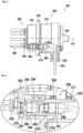
- FIG 2 a side view of an embodiment of a RF multi connector system 100 is shown.
- the connector system has a center axis 110.
- the multi plug connector 200 is connected and locked with the multi socket connector 300.
- This Figure shows the individual RF connectors in more details.
- the plug connector housing 210 of the multi plug connector 200 at least one first coaxial RF connector 290 is provided.
- This connector is attached to a first cable 280.
- the cord grip 230 prevents any mechanical force and at least pulling force by the first cable 280 to the first coaxial RF connectors 290.
- the first coaxial RF connectors 290 may be held within the housing either by a screw connection or a key and slot connection, which would provide easy exchangeability.
- At the multi socket connector 300 at least one of the second connectors 390 is provided. These second connectors match to corresponding first connectors at the multi plug connector.
- the second connectors 390 are attached to second cables 380 for coupling RF signals thereto.
- a cord grip 330 at the multi socket connector avoids pulling force directly to the connector.
- At least one first coaxial RF connector 290 includes a first sealing 279 between a shaft 291 of the at least one first coaxial RF connector and the plug connector housing.
- at least one second coaxial RF connector 390 includes a second sealing 379 between a shaft 391 of the at least one second coaxial RF connector and the socket connector housing.
- at least one housing seal 271 is provided provided between the plug connector housing and the socket connector housing. There may be further housing seals like a rotor seal 271 to seal further openings into the housing, if for example a rotor is penetrating the housing.
- a housing seal which may be a sealing ring 270 between the multi plug connector 200 and the multi socket connector 300 or at least between the plug connector housing 210 and the socket connector housing 310 to seal the connectors against dust, debris, humidity, and water from the outside.
- a lock rotor 250 may lock the multi plug connector 200 and the multi socket connector 300.
- Figure 3 shows a detail of figure 2 .
- the lock rotor 250 is shown in more detail.
- the connector support protrusion 240 is shown in a state mated with the connector support recess 340.
- This figure further shows a second coaxial RF connector 390 which is held by a nut 392 on a thread on the shaft 390 of a second coaxial RF connector 390 in the socket connector housing 310.
- FIG. 4 further details of an embodiment are shown in a sectional view.
- an embodiment of internal cabling within the housing 210 of the multi plug connector 200 is shown.
- Multiple first connectors 290 are attached to multiple first cables 280 which are guided through the cord grip 230.
- the housing 210 comprises an upper shell 212 and a lower shell 213 which allows for easy assembly or disassembly of the housing.
- the first connectors 290 may be held by a snap-in mechanism within the lower shell 213 of the housing.
- An orientation groove 218 may be provided to indicate the correct direction of inserting the multi plug connector into the multi socket connector.
- an embodiment of the multi plug connector is shown in a partially disassembled state.
- the upper shell 212 is separated from the lower shell 213. It may be assembled to the lower shell 213 by a movement into direction 219.
- the upper shell and the lower shell together form cord grip 230, such that the individual first cables 280 may be easily inserted into the lower shell 213.
- the cord grip 230 is secured when the upper shell 212 is attached to the lower shell 213.
- the upper shell 212 may be locked by snapping hocks 214 to the lower shell.
- the multi plug connector 200 may provide at least one or a plurality of positioning grooves 211 which allow a precise positioning of the connectors and guide the connectors through the insertion process of the multi plug connector into the multi socket connector.
- FIG 6 a bottom view of an embodiment of the multi plug connector 200 is shown.
- the first coaxial RF connectors 290 can be seen from their connecting interface side. They are placed in connector recesses 241 of the connector support protrusion 240.
- the first coaxial RF connectors 290 may be placed in such a depth, that they do not protrude from the front surface of support protrusion 240. Therefore, they are protected from mechanical damage, when the connectors are not mated.
- the connector support protrusion 240 has a shape matching to a connector support recess 340 of multi socket connector 300 which will be shown in one of the next figures.
- the connector support protrusion 240 may completely fit into the connector support recess 340, when the connectors are mated.
- the connector support protrusion 240 may have cylindrical shape and may further have a circular, elliptical, rectangular or squared cross section. There may be at least one positioning groove 211 which may interact with at least one positioning notch 311 of multi socket connector 300.
- the lock rotor 250 is shown from its bottom side.
- FIG 7 a top view on the interface of the multi socket connector 300 is shown.
- second connectors 390 may be seen from their interface side.
- the second coaxial RF connectors 390 may be placed in such a depth, that they do not protrude from the front surface of connector support recess 340 and/or the mounting flange 320. Therefore, they are protected from mechanical damage, when the connectors are not mated.
- This Figure also shows three positioning notches 311 which may interface with the positioning grooves 211 of the multi plug connector. Furthermore, the lock stator 350 is shown.
- the lock rotor 250 may have a seal grove 253 for a rotor seal 271 and a support section 257 configured to support a rotor spring 256 shown in more detail in the next figure.
- This rotor spring is shown there as a disc spring, but may also be an elastic sealing ring.
- This rotor spring may provide a tension between the connector housings, when in a locked state.
- the rotor center axis 259 may be the center axis of the multi plug connector 200 and the multi socket connector 300.
- the lock rotor 250 may be held by the multi plug connector 200 and it may have an outer thread 254 which interfaces with an inner thread 354 of the lock stator 350.
- the multi socket connector 300 may include a lock rotor 250 which may comprise an outer thread 254 matching to an inner thread 354 of the multi plug connector 200.
- the outer thread 254 may be a combination of a thread and a key and slot lock. It may comprise only segments of a thread separated by grooves 255.
- a locking knob 220 may be attached. There may also be a hex end for a hex nut, or any other end adapted for any tool, which may be a special tool to avoid unauthorized operation.
- Figure 9 shows an exemplary curve of the locking distance versus rotation angle of the locking movement of lock rotor 250.
- the movement between the connector housings is linear to a total distance of about 2.5mm. With further rotation, there is no movement. This ensures in combination with a tensioning by the spring 256 a smooth and secure locking. Beyond the 160 degrees position, which may be close to a 180 degrees position, the lock 251, 252 may engage and block any unintentional rotation.
- Figure 10 shows an embodiment including a pair of mated coaxial RF connectors in a detailed sectional view.
- a first coaxial RF connector 290 is mated to a second coaxial RF connector 390.
- the first coaxial RF connector 290 comprises a first center conductor 293 which may have a male contact and a first outer conductor 294 which may be a solid tube.
- the second coaxial RF connector 390 comprises a second center conductor 393 which may have a female contact configured to contact the first center conductor 293 and a second outer conductor 394 which may be a slotted tube configured to contact the first outer conductor 294.
- the second coaxial RF connector 390 further comprises a second outer sheath 395 surrounding and protecting the slotted outer conductor. Male and female configurations of the inner and outer conductors may be exchanged.
- the first coaxial RF connector 290 may comprise a first outer insulation 295 surrounding the first outer conductor 294.
- the first outer insulation 295 may center the first outer conductor 294 within the second outer sheath 395 and at the same time provides a galvanic insulation such that there is only one DC and low frequency current path of the outer conductors between the second outer conductor 394 and the first outer conductor 294.
- This figure further indicates the distance 345 between the highest extension at front surface of multi socket connector 300 and the second outer sheath 395. So, the second coaxial RF connector 390 is set back within connector support recess 340 which provides a mechanical protection. Further, the distance 245 between the first coaxial RF connector 290 and the end of the connector support protrusion 240 is indicated. Also here, the first coaxial RF connector 290 is set back which provides a mechanical protection.
- Figure 11 shows an embodiment including a key and slot locking mechanism configured to hold first coaxial RF connectors 290 in the plug connector housing 210.
- the mechanism comprises a locking key 292 at the connector and a locking slot 272 at the connector support protrusion 240.
- a connector sealing ring 279 is provided for tensioning a connector sealing ring 279 is provided.
- the second coaxial RF connectors may have a key and slot locking mechanism. Such a locking mechanism simplifies insertion and/or exchange of the connectors into the housing. It further provides a precise positioning of the connectors within the housing.
- Figure 12 shows an embodiment with a different locking mechanism using a slotted ring 298 which may have a chamfered edge and is compressed for insertion of the connector.
- a slotted ring 298 which may have a chamfered edge and is compressed for insertion of the connector.
- the ring expands into a groove 297 which is in the plug connector housing 210 and locks the connector 290 into the housing.
- This figure further shows a sectional view of a first coaxial RF connector 290 including a first center conductor 293 and a first outer conductor 294.
- the second coaxial RF connectors may have a slotted ring mechanism. The slotted ring mechanism most simplifies assembly, as the connector may only be snapped into the housing.
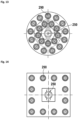
- Figure 13 shows a circular multi-row arrangement of coaxial RF connectors.
- Figure 14 shows a rectangular arrangement of coaxial RF connectors. These circular and rectangular embodiments basically show alternatives to the connector arrangements of figures 5 and 6 . Basically, any number of coaxial RF connectors may be provided.
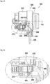
- Figure 15 shows a further embodiment of a RF multi connector system 102 with combined seal 400, which combines the function of first sealing 279 and further sealing.
- the combined seal may seal the shafts of all first coaxial RF connectors 290 against the plug connector housing.
- the combined seal may further seal the rotor against the housing.
- Figure 16 shows a section of the previous figure. Here, different sections of the combined seal 400 are shown in more detail.
- a center seal section 410 may provide a seal of the rotor.
- Multiple connector seal sections 420 seal the shafts of all first coaxial RF connectors 290.
- the outer seal section 430 contacts the housing and therefore provides a seal against the housing.
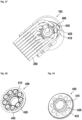
- Figure 17 shows a rear view a RF multi connector system 102 with a view on the combines seal 400.
- Figure 18 shows a top view of the combined seal with a center seal section 410, multiple connector seal sections 420, and an outer seal section 430.
- the center seal section 410 may include a protruding ring on a first side of the combined seal, located at the center of the combined seal.
- the connector seal sections 420 may be aranged around the center seal section. They may be arranged on a circle around a center axis of the combined seal. They may include multiple protrusions for accommodating the connectors. The protrusions may be oriented in or against an opposite direction to the center seal section.
- the outer seal section 430 may be a ring shaped lip at the outer rim of the combined seal. It may also be on a protrusion.
- the combined seal may only include the connector seal sections 420 and the outer seal section 430 if the center seal section 410 is not required.
- Figure 19 shows a bottom view of the combined seal.
Landscapes
- Details Of Connecting Devices For Male And Female Coupling (AREA)
- Connector Housings Or Holding Contact Members (AREA)
- Coupling Device And Connection With Printed Circuit (AREA)
Description
- The invention relates to a multi coaxial connector system for radio frequency (RF) signals including a plurality of RF connectors.
-
US 2019/0312394 A1 discloses a ganged coaxial connector assembly. A pair of shells holds a plurality of mating connector pairs. The electrical contact system of each connector pair has a seal between each connector and its counter connector. Sealing is established each time, when the connectors of a connector pair are mated. This requires comparatively high plugging and unplugging forces which multiply with the number of connectors in a shell to very high total forces for plugging or unplugging a shell. To apply the high forces and to hold the connectors in predetermined axial positions, in embodiments with more than four connectors, the connectors are spring loaded. The space holding the springs and the space surrounding the connectors is not sealed, such that water may penetrate therein. When this water freezes, the spring does no more work, such that the sealing between the connectors may be affected. Further, freezing water expands and may damage the connector assembly. The locking mechanism comprising a latch and locking pin is outside of the connector and may freeze too. It is difficult to remove ice from the small parts like the locking pins without damaging them. Finally, it may no more be possible to disconnect the coaxial connector assembly. -
CN 104617446 B discloses a radio frequency connector according to the preamble ofclaim 1. - The problem to be solved by the invention is to provide a multi coaxial RF connector system having improved robustness, which is easy to connect and disconnect with lower forces and can be manufactured for reduced costs. Further, the connector system should be usable under freezing conditions.
- Solutions of the problem are described in the
independent claim 1. The dependent claims relate to further improvements of the invention. - A RF multi connector system includes a RF multi plug connector and a RF multi socket connector matching to the RF multi connector.
- The multi connector and the multi counter connector hold a plurality of individual connectors, which may be coaxial RF (radio frequency) connectors. These coaxial connectors may be plug connectors, socket connectors, or hermaphroditic connectors. The multi plug connector comprises a housing for holding the individual RF connectors at predetermined positions. The multi socket connector comprises a further housing matching to the multi plug connector and which further comprises a plurality of positions for holding individual RF connectors. The connector holding positions of the multi socket connector match to the connector holding positions of the multi plug connector, such that the multi plug connector and the multi socket connector can be mated. The individual RF connectors at the multi plug connector and the multi socket connector are selected such that matching connector pairs exist. For example, an individual RF socket connector may be at a certain position at the multi plug connector, whereas an individual RF plug connector is at the corresponding position of the multi socket connector. There may be any order of plug and socket connectors and hermaphroditic connectors within the multi plug connector and the multi socket connector, as long as they match together. In addition, there may be other connectors, for example for grounding or for signal transmission.
- The multi plug connector comprises a connector support protrusion which may have a shape matching to a connector support recess of a multi socket connector. The connector support protrusion may completely fit into the connector support recess, when the connectors are mated. The connector support protrusion may have cylindrical shape and may further have a circular, elliptical, rectangular or squared cross section. The multi plug connector and the multi socket connector may have a cylindrical shape with a locking mechanism at its center. All individual RF connectors may be arranged in a circle. Groups of RF connectors may be arranged in different circles. Basically, connectors may be arranged in one or in a plurality of circles around the center. In another embodiment, a plurality of the first connectors and a plurality of second connectors is arranged in a row or in a plurality of rows.
- For higher frequencies, the dimension of the individual RF connectors decrease in size, and the structure of these connectors gets more and more delicate. Therefore, a straight insertion of the connectors when connecting the multi plug connector to the multi socket connector is necessary. Tilting or jamming of the connectors must be avoided under any circumstances. The centralized locking mechanisms together with the circular arrangement of the individual RF connectors results in a comparatively symmetric shape of the connector. The closing force is applied by the central locking mechanism, and therefore an even force distribution to the circularly arranged individual connectors is ensured. Furthermore, positioning and guiding grooves and notches may be provided in the multi plug connector and the multi socket connector. These grooves and notches further provide a straight guidance when connecting the multi plug connector with the multi socket connector.
- To compensate for minor mechanical tolerances, the individual RF connectors may be fixed to their positions of the multi socket connector and the individual RF connectors at the multi plug connector may be mounted tiltable and/or movable in a radial direction thereto. This movability may only be within a comparatively small range which may be less than 2 mm, less than 1 mm, or less than 0.5 mm. An axial mobility is not required and may not be desired.
- The central locking mechanism may comprise a threaded key and slot lock which is a combination of a thread and a key and slot connection. This will allow to engage the thread at a certain position and to generate a comparatively large distance of movement with a small angle of rotation. The locking mechanism may comprise a lock rotor at the multi plug connector and the lock stator at the multi socket connector. The rotor is rotatable and may be operated by a locking knob which may cover a larger section of the top surface of the multi plug connector or even all the top surface thereof. The lock stator may be fixed to the multi socket connector.
- There may be a plurality of positioning notch/groove pairs which improve guidance when mating the connectors and may make multi plug connector/multi socket connector pairs unique, such that individual connectors cannot be combined with other connectors having notches and/or grooves at other position.
- At least one first coaxial RF connector includes a first sealing between a shaft of the at least one first coaxial RF connector and the plug connector housing. Further, at least one second coaxial RF connector includes a second sealing between a shaft of the at least one second coaxial RF connector and the socket connector housing. Also, at least one housing seal is provided between the plug connector housing and the socket connector housing. There may be further housing seals like a rotor seal to seal further openings into the housing, if for example a rotor is penetrating the housing. Here, the interior of the connector housing including the connectors is sealed against dust, debris, humidity, and water from the outside. Therefore, no water may penetrate into the contact systems of the connectors. Further, no water may penetrate into the surrounding of the connectors, such that the connector may be operated (connected and disconnected) even at freezing temperatures, as no ice may block internal parts of the connector.
- In an embodiment, there may be a combined seal for sealing the shafts of all of the at least one first coaxial RF connectors and the plug connector housing. The combined seal may also provide a seal of the rotor against the housing. Therefore, the combined seal is a combination of first sealing and second sealing.
- Also, a solid locking knob on top of the connector can easily be cleaned from ice and be operated with thick globes. There are no small parts outside the connector, which may be blocked by ice. The whole locking mechanism is embedded into the housing, such that it cannot freeze. In an embodiment, a key and slot locking mechanism may be provided to hold first coaxial RF connectors in the plug connector housing and/or second coaxial RF connectors in the socket connector housing. The mechanism may include a locking key at the connector and a locking slot at the housing. Such a locking mechanism simplifies insertion and/or exchange of the connectors into the housing.
- In another embodiment, a locking mechanism using a slotted ring which may have a chamfered edge and is compressed for insertion of the connector, may be provided. When the connector is in place, the ring expands into a groove which is in the housing and locks the connector into the housing.
- Further, a coaxial RF connector may be held by a nut on a thread on the shaft of the coaxial RF connector in the socket connector housing or the plug connector housing.
- The embodiments of key and slot, slotted ring and nut do not need a spring for axially moving the connector.
- The housings of the multi connector and the multi counter connector may comprise metal and/or a dielectric material like a plastic or polymer material or the connectors may be coated with such a material at all contact surfaces which may enter into contact with the other connector. The connector housings may exclusively comprise of a dielectric material or multiple dielectric material. They may not comprise any metal or low impedance electrically conductive material. The only electrical connection between the multi connector and the multi counter connector may be by the coaxial RF connectors. This may improve passive inter-modulation characteristics even if used in the close proximity of a radiating antenna.
- The first and second coaxial RF connectors may be any combination of plug and socket connectors. In an embodiment, the RF multi connector system comprises only coaxial RF connectors, but there may be at least one or a low number of other connectors, for example power or signal connectors including optical connectors.
- The abbreviation RF for radio frequency is used also for microwave.
- In general, the features of the multi plug connector may be exchanged with the multi socket connector.
- In the following the invention will be described by way of example, without limitation of the general inventive concept, on examples of embodiment with reference to the drawings.
-
Figure 1 shows a perspective view of the RF multi connector system. -
Figure 2 shows a side view of an RF multi connector system. -
Figure 3 shows a detail offigure 2 . -
Figure 4 shows further details in a sectional view. -
Figure 5 shows the multi plug connector in a partially disassembled state. -
Figure 6 shows a bottom view of the multi plug connector. -
Figure 7 shows a top view on the interface of the multi socket connector. -
Figure 8 shows lock rotor and lock stator in more detail. -
Figure 9 shows an exemplary curve of the locking distance versus rotation angle. -
Figure 10 shows a pair of mated coaxial RF connectors in detail. -
Figure 11 shows a key and slot locking mechanism. -
Figure 12 shows a locking mechanism using a slotted ring. -
Figure 13 shows a circular multi-row arrangement of coaxial RF connectors. -
Figure 14 shows a rectangular arrangement of coaxial RF connectors. -
Figure 15 shows a further embodiment with combined seal. -
Figure 16 shows a section of the previous figure. -
Figure 17 shows a rear view. -
Figure 18 shows a top view of the combined seal. -
Figure 19 shows a bottom view of the combined seal. - In
Figure 1 , a perspective view of an embodiment of the RFmulti connector system 100 is shown. It comprises amulti plug connector 200 and amulti socket connector 300. Themulti plug connector 200 comprises aplug connector housing 210 with a lockingknob 220 which may be rotated to lock or unlock themulti plug connector 200, as indicated byarrow 221. There may be acord grip 230 to hold first cables for RF signals. The locking knob is partially cut to show part of the locking mechanism comprising alock rotor 250. There may further be a lock, which may include arotor arm 251 which interacts with arotor notch 252 to hold the rotor in certain positions, which may be at least a locked position of the connector and an unlocked position. The lock may be part of the locking knob (220) or of the lock rotor (250). The socket connector comprises asocket connector housing 310 further comprises a mountingflange 320 having at least one flange screw-hole 321 for mounting the flange to a housing or an antenna or any other part. - In
Figure 2 , a side view of an embodiment of a RFmulti connector system 100 is shown. The connector system has acenter axis 110. Here again, themulti plug connector 200 is connected and locked with themulti socket connector 300. This Figure shows the individual RF connectors in more details. In theplug connector housing 210 of themulti plug connector 200, at least one firstcoaxial RF connector 290 is provided. This connector is attached to afirst cable 280. Thecord grip 230 prevents any mechanical force and at least pulling force by thefirst cable 280 to the firstcoaxial RF connectors 290. The firstcoaxial RF connectors 290 may be held within the housing either by a screw connection or a key and slot connection, which would provide easy exchangeability. - At the
multi socket connector 300, at least one of thesecond connectors 390 is provided. These second connectors match to corresponding first connectors at the multi plug connector. Thesecond connectors 390 are attached tosecond cables 380 for coupling RF signals thereto. Acord grip 330 at the multi socket connector avoids pulling force directly to the connector. - At least one first
coaxial RF connector 290 includes a first sealing 279 between ashaft 291 of the at least one first coaxial RF connector and the plug connector housing. Further, at least one secondcoaxial RF connector 390 includes asecond sealing 379 between ashaft 391 of the at least one second coaxial RF connector and the socket connector housing. Also, at least onehousing seal 271 is provided provided between the plug connector housing and the socket connector housing. There may be further housing seals like arotor seal 271 to seal further openings into the housing, if for example a rotor is penetrating the housing. - There is a housing seal, which may be a sealing
ring 270 between themulti plug connector 200 and themulti socket connector 300 or at least between theplug connector housing 210 and thesocket connector housing 310 to seal the connectors against dust, debris, humidity, and water from the outside. Alock rotor 250 may lock themulti plug connector 200 and themulti socket connector 300. -
Figure 3 shows a detail offigure 2 . Here, thelock rotor 250 is shown in more detail. Furthermore, theconnector support protrusion 240 is shown in a state mated with theconnector support recess 340. This figure further shows a secondcoaxial RF connector 390 which is held by anut 392 on a thread on theshaft 390 of a secondcoaxial RF connector 390 in thesocket connector housing 310. - In
Figure 4 , further details of an embodiment are shown in a sectional view. Here, an embodiment of internal cabling within thehousing 210 of themulti plug connector 200 is shown. Multiplefirst connectors 290 are attached to multiplefirst cables 280 which are guided through thecord grip 230. Thehousing 210 comprises anupper shell 212 and alower shell 213 which allows for easy assembly or disassembly of the housing. Thefirst connectors 290 may be held by a snap-in mechanism within thelower shell 213 of the housing. Anorientation groove 218 may be provided to indicate the correct direction of inserting the multi plug connector into the multi socket connector. - In
Figure 5 , an embodiment of the multi plug connector is shown in a partially disassembled state. Here, theupper shell 212 is separated from thelower shell 213. It may be assembled to thelower shell 213 by a movement intodirection 219. The upper shell and the lower shell together formcord grip 230, such that the individualfirst cables 280 may be easily inserted into thelower shell 213. Thecord grip 230 is secured when theupper shell 212 is attached to thelower shell 213. Theupper shell 212 may be locked by snappinghocks 214 to the lower shell. Themulti plug connector 200 may provide at least one or a plurality ofpositioning grooves 211 which allow a precise positioning of the connectors and guide the connectors through the insertion process of the multi plug connector into the multi socket connector. - In
Figure 6 , a bottom view of an embodiment of themulti plug connector 200 is shown. Here, the firstcoaxial RF connectors 290 can be seen from their connecting interface side. They are placed in connector recesses 241 of theconnector support protrusion 240. The firstcoaxial RF connectors 290 may be placed in such a depth, that they do not protrude from the front surface ofsupport protrusion 240. Therefore, they are protected from mechanical damage, when the connectors are not mated. - The
connector support protrusion 240 has a shape matching to aconnector support recess 340 ofmulti socket connector 300 which will be shown in one of the next figures. Theconnector support protrusion 240 may completely fit into theconnector support recess 340, when the connectors are mated. Theconnector support protrusion 240 may have cylindrical shape and may further have a circular, elliptical, rectangular or squared cross section. There may be at least onepositioning groove 211 which may interact with at least onepositioning notch 311 ofmulti socket connector 300. There may be a plurality of such positioning notch/groove pairs which improve guidance when mating the connectors and may make multi plug connector/multi socket connector pairs unique, such that individual connectors cannot be combined with other connectors having notches and/or grooves at other position. In general, there may also be notches at the multi plug connector and grooves at the multi socket connector or vice versa. Furthermore, thelock rotor 250 is shown from its bottom side. - In
Figure 7 , a top view on the interface of themulti socket connector 300 is shown. Here,second connectors 390 may be seen from their interface side. The secondcoaxial RF connectors 390 may be placed in such a depth, that they do not protrude from the front surface ofconnector support recess 340 and/or the mountingflange 320. Therefore, they are protected from mechanical damage, when the connectors are not mated. - This Figure also shows three
positioning notches 311 which may interface with thepositioning grooves 211 of the multi plug connector. Furthermore, thelock stator 350 is shown. - In
Figure 8 , embodiments of thelock rotor 250 and thelock stator 350 are shown in more detail. Thelock rotor 250 may have aseal grove 253 for arotor seal 271 and a support section 257 configured to support arotor spring 256 shown in more detail in the next figure. This rotor spring is shown there as a disc spring, but may also be an elastic sealing ring. This rotor spring may provide a tension between the connector housings, when in a locked state. Therotor center axis 259 may be the center axis of themulti plug connector 200 and themulti socket connector 300. Thelock rotor 250 may be held by themulti plug connector 200 and it may have anouter thread 254 which interfaces with aninner thread 354 of thelock stator 350. In another embodiment, themulti socket connector 300 may include alock rotor 250 which may comprise anouter thread 254 matching to aninner thread 354 of themulti plug connector 200. Theouter thread 254 may be a combination of a thread and a key and slot lock. It may comprise only segments of a thread separated bygrooves 255. At the top end opposing the thread, a lockingknob 220 may be attached. There may also be a hex end for a hex nut, or any other end adapted for any tool, which may be a special tool to avoid unauthorized operation. -
Figure 9 shows an exemplary curve of the locking distance versus rotation angle of the locking movement oflock rotor 250. At angles between 0 and 160 degrees the movement between the connector housings is linear to a total distance of about 2.5mm. With further rotation, there is no movement. This ensures in combination with a tensioning by the spring 256 a smooth and secure locking. Beyond the 160 degrees position, which may be close to a 180 degrees position, thelock -
Figure 10 shows an embodiment including a pair of mated coaxial RF connectors in a detailed sectional view. A firstcoaxial RF connector 290 is mated to a secondcoaxial RF connector 390. The firstcoaxial RF connector 290 comprises afirst center conductor 293 which may have a male contact and a firstouter conductor 294 which may be a solid tube. The secondcoaxial RF connector 390 comprises asecond center conductor 393 which may have a female contact configured to contact thefirst center conductor 293 and a secondouter conductor 394 which may be a slotted tube configured to contact the firstouter conductor 294. The secondcoaxial RF connector 390 further comprises a secondouter sheath 395 surrounding and protecting the slotted outer conductor. Male and female configurations of the inner and outer conductors may be exchanged. - The first
coaxial RF connector 290 may comprise a first outer insulation 295 surrounding the firstouter conductor 294. The first outer insulation 295 may center the firstouter conductor 294 within the secondouter sheath 395 and at the same time provides a galvanic insulation such that there is only one DC and low frequency current path of the outer conductors between the secondouter conductor 394 and the firstouter conductor 294. - This figure further indicates the
distance 345 between the highest extension at front surface ofmulti socket connector 300 and the secondouter sheath 395. So, the secondcoaxial RF connector 390 is set back withinconnector support recess 340 which provides a mechanical protection. Further, thedistance 245 between the firstcoaxial RF connector 290 and the end of theconnector support protrusion 240 is indicated. Also here, the firstcoaxial RF connector 290 is set back which provides a mechanical protection. -
Figure 11 shows an embodiment including a key and slot locking mechanism configured to hold firstcoaxial RF connectors 290 in theplug connector housing 210. The mechanism comprises a locking key 292 at the connector and alocking slot 272 at theconnector support protrusion 240. For tensioning aconnector sealing ring 279 is provided. In addition or alternatively, the second coaxial RF connectors may have a key and slot locking mechanism. Such a locking mechanism simplifies insertion and/or exchange of the connectors into the housing. It further provides a precise positioning of the connectors within the housing. -
Figure 12 shows an embodiment with a different locking mechanism using a slottedring 298 which may have a chamfered edge and is compressed for insertion of the connector. When theconnector 290 is in place, the ring expands into agroove 297 which is in theplug connector housing 210 and locks theconnector 290 into the housing. This figure further shows a sectional view of a firstcoaxial RF connector 290 including afirst center conductor 293 and a firstouter conductor 294. In addition or alternatively, the second coaxial RF connectors may have a slotted ring mechanism. The slotted ring mechanism most simplifies assembly, as the connector may only be snapped into the housing. -
Figure 13 shows a circular multi-row arrangement of coaxial RF connectors. -
Figure 14 shows a rectangular arrangement of coaxial RF connectors. These circular and rectangular embodiments basically show alternatives to the connector arrangements offigures 5 and6 . Basically, any number of coaxial RF connectors may be provided. -
Figure 15 shows a further embodiment of a RFmulti connector system 102 with combinedseal 400, which combines the function of first sealing 279 and further sealing. - The combined seal may seal the shafts of all first
coaxial RF connectors 290 against the plug connector housing. The combined seal may further seal the rotor against the housing. -
Figure 16 shows a section of the previous figure. Here, different sections of the combinedseal 400 are shown in more detail. Acenter seal section 410 may provide a seal of the rotor. Multipleconnector seal sections 420 seal the shafts of all firstcoaxial RF connectors 290. Theouter seal section 430 contacts the housing and therefore provides a seal against the housing. -
Figure 17 shows a rear view a RFmulti connector system 102 with a view on the combines seal 400. -
Figure 18 shows a top view of the combined seal with acenter seal section 410, multipleconnector seal sections 420, and anouter seal section 430. Thecenter seal section 410 may include a protruding ring on a first side of the combined seal, located at the center of the combined seal. Theconnector seal sections 420 may be aranged around the center seal section. They may be arranged on a circle around a center axis of the combined seal. They may include multiple protrusions for accommodating the connectors. The protrusions may be oriented in or against an opposite direction to the center seal section. Theouter seal section 430 may be a ring shaped lip at the outer rim of the combined seal. It may also be on a protrusion. The combined seal may only include theconnector seal sections 420 and theouter seal section 430 if thecenter seal section 410 is not required. -
Figure 19 shows a bottom view of the combined seal. -
- 100
- RF multi connector system
- 102
- RF multi connector system with combined seal
- 110
- center axis
- 200
- multi plug connector
- 210
- plug connector housing
- 211
- positioning groove
- 212
- upper shell
- 213
- lower shell
- 214
- locks
- 218
- orientation groove
- 219
- assembly of connector housing shells
- 220
- locking knob
- 221
- rotation of locking knob
- 230
- cord grip
- 240
- connector support protrusion
- 241
- connector recess
- 245
- distance between first coaxial RF connector and connector support protrusion
- 250
- lock rotor
- 251
- rotor arm
- 252
- rotor notch
- 253
- seal groove
- 254
- outer thread
- 255
- thread grooves
- 256
- rotor spring
- 257
- support section
- 259
- center axis
- 260
- connector guidance bush
- 270
- sealing ring
- 271
- rotor seal
- 272
- locking slot
- 279
- first connector sealing ring
- 280
- first cables
- 290
- first coaxial RF connectors
- 291
- shaft of first coaxial RF connector
- 292
- locking key
- 293
- first center conductor
- 294
- first outer conductor
- 295
- first outer insulation
- 297
- groove in plug connector housing
- 298
- slotted ring
- 300
- multi socket connector
- 310
- socket connector housing
- 311
- positioning notch
- 320
- mounting flange
- 321
- flange screw hole
- 340
- connector support recess
- 345
- distance between second coaxial RF connector and multi socket connector
- 350
- lock stator
- 354
- inner thread
- 360
- connector guidance socket
- 279
- second connector sealing ring
- 380
- second cables
- 390
- second coaxial RF connectors
- 391
- shaft of second coaxial RF connector
- 392
- nut
- 393
- second center conductor
- 394
- second outer conductor
- 395
- second outer sheath
- 400
- combined seal
- 410
- center seal section
- 420
- connector seal sections
- 430
- outer seal section
Claims (15)
- RF multi connector system (100) comprising a multi plug connector (200) and a multi socket connector (300),the multi plug connector (200) comprises a plug connector housing (210), the plug connector housing (210) further comprising a connector support protrusion (240) having a plurality of connector recesses (241), the plurality of connector recesses (241) each holding a first coaxial RF connector (290), each first RF connector comprising an center conductor (293) and an outer conductor (294);the multi socket connector (300) comprises a socket connector housing (310), the socket connector housing (310) further comprising a connector support recess (340), the connector support recess (340) holding a plurality of second coaxial RF connectors (390),wherein the multi plug connector (200) matches to the multi socket connector (300) such that the connector support protrusion (240) fits into the connector support recess (340), and the plurality of first coaxial RF connectors (290) matches to the plurality of second coaxial RF connectors (390), each second RF connector comprising an center conductor (393) and an outer conductor (394);at least one housing seal (270) is provided between the plug connector housing (210) and the socket connector housing (310);characterized in, that at least one of the plurality of first coaxial RF connectors (290) comprises a first sealing (279) between a shaft (291) of the at least one of the plurality of first coaxial RF connectors and the plug connector housing (210), at least one of the plurality of second coaxial RF connectors (390) comprises a second sealing (379) between a shaft (391) of the at least one of the plurality of second coaxial RF connectors and the socket connector housing (310).
- RF multi connector system (100) according to any of the previous claims, characterized in, that
the connector support protrusion (240) has a circular outer contour around a center axis (110) and the connector support recess (340) has a circular inner contour around the center axis (110). - RF multi connector system (100) according to any of the previous claims, characterized in, that the plurality of the first coaxial RF connectors (290) and the plurality of second coaxial RF connectors (390) is arranged on a circle around a center axis (110).
- RF multi connector system (100) according to claim 1 or 2, characterized in, that the plurality of the first coaxial RF connectors (290) and the plurality of second coaxial RF connectors (390) is arranged in a row or in a plurality of rows.
- RF multi connector system (100) according to any of the previous claims, characterized in, that
the connector recesses (241) have a depth, such that the first connectors (290) do not extend beyond the connector recesses (241). - RF multi connector system (100) according to any of the previous claims, characterized in, that
the connector support recess (340) has a depth, such that the at least one second connector (390) do not extend beyond the connector support recess (340). - RF multi connector system (100) according to any of the previous claims, characterized in, that
the connector support protrusion (240) comprises at least one positioning groove (211) or positioning notch matching to at least one positioning notch (311) or positioning groove at the connector support recess (340). - RF multi connector system (100) according to the previous claim, characterized in, thatthe multi plug connector (200) comprises a lock rotor (250), the lock rotor (250) comprising an outer thread (254), the outer thread matching to an inner thread (354) of the multi socket connector (300) orthe multi socket connector (300) comprises a lock rotor (250), the lock rotor (250) comprising an outer thread (254), the outer thread matching to an inner thread (354) of the multi plug connector (200).
- RF multi connector system (100) according to the previous claim, characterized in, that
the lock rotor (250) is configured to rotate around the center axis (110) and the lock rotor (250) may be limited in its rotation angle to less than one of 360°, 270°, 180° and 90°. - RF multi connector system (100) according to any of claims 8 to 9, characterized in, thatthe lock rotor (250) is connected to a locking knob (220) andthe locking knob (250) may comprise a lock (251, 252) to hold the rotor at least in a locked position.
- RF multi connector system (100) according to any of the previous claims, characterized in, that
the outer thread (254) of the lock rotor (250) has a plurality of longitudinal thread grooves (255). - RF multi connector system (100) according to any of the previous claims, characterized in, thatat least one of the plurality of first coaxial RF connectors (290) comprises a locking key (292) and the plug connector housing (210) comprises a matching locking slot (272) at a connector support protrusion (240) for forming a key and slot locking mechanism and/orat least one of the plurality of second coaxial RF connectors (390) comprises a locking key and the socket connector housing (310) comprises a matching locking slot at a connector support protrusion for forming a key and slot locking mechanism.
- RF multi connector system (100) according to any of claims 1-11, characterized in, thatat least one of the plurality of first coaxial RF connectors (290) is held by a slotted ring (298) in a groove (297) of the plug connector housing (210) and/orat least one of the plurality of second coaxial RF connectors (390) is held by a slotted ring in a groove of the socket connector housing (310).
- RF multi connector system (100) according to any of claims 1-11, characterized in, thatat least one of the plurality of first coaxial RF connectors (290) is held by a nut on a thread on the shaft of the at least one first coaxial RF connector (290) in the plug connector housing (210) and/orat least one of the plurality of second coaxial RF connectors (390) is held by a nut (392) on a thread on the shaft of the at least one second coaxial RF connector (390) in the socket connector housing (310).
- RF multi connector system (100) according to any of the previous claims, characterized in, that a combined seal (400) combines the first sealing (279) and further sealing by providing a center seal section (410) configured to seal a rotor (250), a plurality of connector seal sections (420) configured to seal the shafts of the plurality of the first coaxial RF connectors (290), and an outer seal section (430) configured to seal the housing.
Applications Claiming Priority (1)
| Application Number | Priority Date | Filing Date | Title |
|---|---|---|---|
| EP19211464.3A EP3829007A1 (en) | 2019-11-26 | 2019-11-26 | Multi-rf connector system |
Publications (3)
| Publication Number | Publication Date |
|---|---|
| EP3829006A1 EP3829006A1 (en) | 2021-06-02 |
| EP3829006C0 EP3829006C0 (en) | 2024-10-16 |
| EP3829006B1 true EP3829006B1 (en) | 2024-10-16 |
Family
ID=68696316
Family Applications (2)
| Application Number | Title | Priority Date | Filing Date |
|---|---|---|---|
| EP19211464.3A Withdrawn EP3829007A1 (en) | 2019-11-26 | 2019-11-26 | Multi-rf connector system |
| EP20205454.0A Active EP3829006B1 (en) | 2019-11-26 | 2020-11-03 | Multi-rf connector system |
Family Applications Before (1)
| Application Number | Title | Priority Date | Filing Date |
|---|---|---|---|
| EP19211464.3A Withdrawn EP3829007A1 (en) | 2019-11-26 | 2019-11-26 | Multi-rf connector system |
Country Status (6)
| Country | Link |
|---|---|
| US (1) | US20220285896A1 (en) |
| EP (2) | EP3829007A1 (en) |
| JP (1) | JP2023503169A (en) |
| KR (1) | KR102907766B1 (en) |
| CN (1) | CN114747100A (en) |
| WO (1) | WO2021104807A1 (en) |
Families Citing this family (6)
| Publication number | Priority date | Publication date | Assignee | Title |
|---|---|---|---|---|
| WO2022109299A1 (en) * | 2020-11-20 | 2022-05-27 | New York University | Anti-galectin-9 antibodies and therapeutic uses thereof |
| EP4297194A1 (en) * | 2022-06-23 | 2023-12-27 | Airbus Defence and Space Limited | Multi-way radio frequency interface and connector |
| WO2024086228A1 (en) * | 2022-10-21 | 2024-04-25 | Interplex Industries, Inc. | Electrical coupling apparatus |
| WO2024179663A1 (en) | 2023-02-28 | 2024-09-06 | Telefonaktiebolaget Lm Ericsson (Publ) | Rf multi connector unit for antennas, antenna system and base station |
| FR3155373A1 (en) * | 2023-11-10 | 2025-05-16 | Factem | Connector comprising a fixing contact |
| TWI908554B (en) * | 2024-12-20 | 2025-12-11 | 進聯工業股份有限公司 | Linkage structure of energy storage connector |
Citations (3)
| Publication number | Priority date | Publication date | Assignee | Title |
|---|---|---|---|---|
| CN105428874A (en) * | 2015-12-15 | 2016-03-23 | 贵州航天电器股份有限公司 | Hydraulic seal electrical connector |
| EP3223371A2 (en) * | 2016-03-23 | 2017-09-27 | TE Connectivity Germany GmbH | Power-electric contact device; exchangeable power-electric contact module as well as power-electric connector |
| CN209266765U (en) * | 2018-12-04 | 2019-08-16 | 江苏联海通信股份有限公司 | A kind of collection beam is inclined coaxial connector |
Family Cites Families (25)
| Publication number | Priority date | Publication date | Assignee | Title |
|---|---|---|---|---|
| US2457119A (en) * | 1942-03-06 | 1948-12-28 | Int Standard Electric Corp | Electrical connector |
| US3853381A (en) * | 1973-06-14 | 1974-12-10 | Amp Inc | Jackscrew retainer |
| JP2613998B2 (en) * | 1992-07-10 | 1997-05-28 | 矢崎総業株式会社 | Mating structure of low insertion force connector |
| US6478619B1 (en) * | 2001-09-10 | 2002-11-12 | Wayne Wiechmann | Electrical connector |
| JP2003222116A (en) * | 2002-01-31 | 2003-08-08 | Honda Motor Co Ltd | Self tapping bolt |
| US7223131B2 (en) | 2005-09-02 | 2007-05-29 | Tyco Electronics Corporation | Three position electrical connector assembly |
| DE102007059357A1 (en) * | 2007-12-07 | 2009-06-10 | Erich Jaeger Gmbh & Co. Kg | Socket and method for its manufacture |
| WO2011059452A1 (en) * | 2009-11-16 | 2011-05-19 | Cooper Technologies Company | Stackable cable mount power connector |
| DE102012202225B4 (en) * | 2012-02-14 | 2015-10-22 | Te Connectivity Germany Gmbh | Plug housing with seal |
| GB201208535D0 (en) * | 2012-05-15 | 2012-06-27 | Tronic Ltd | Underwater electrical connection and termination assemblies |
| CN203645042U (en) * | 2013-11-25 | 2014-06-11 | 泰兴市航天电器有限公司 | Connector sealing device |
| JP3214627U (en) * | 2015-02-13 | 2018-02-01 | 常州市新盛電器有限公司Changzhou Xinsheng Electronics Co.,Ltd | Focused plug-in self-locking high-frequency connector assembly |
| CN104617446B (en) * | 2015-02-13 | 2016-08-24 | 常州市新盛电器有限公司 | Boundling fast-insertion self-locking RF connector assembly |
| CN204424580U (en) * | 2015-02-13 | 2015-06-24 | 常州市新盛电器有限公司 | The cable clamping mechanism of cluster radio connector |
| US10978840B2 (en) * | 2018-04-04 | 2021-04-13 | Commscope Technologies Llc | Ganged coaxial connector assembly |
| CN205900861U (en) * | 2016-07-26 | 2017-01-18 | 吴通控股集团股份有限公司 | Multichannel connector |
| US10148049B2 (en) * | 2016-09-14 | 2018-12-04 | Te Connectivity Corporation | RF connector system having connector cavities with side openings |
| DE202017101060U1 (en) * | 2017-02-24 | 2018-05-25 | Fct Electronic Gmbh | Connector, in particular for high-current application |
| CN206673214U (en) * | 2017-03-30 | 2017-11-24 | 谈振新 | Pushing self-locking cluster radio coaxial connector assemblies |
| CN206673271U (en) * | 2017-03-30 | 2017-11-24 | 谈振新 | Boundling female radio frequency (RF) coaxial connector |
| CN206673272U (en) * | 2017-03-30 | 2017-11-24 | 谈振新 | Removable boundling male radio frequency (RF) coaxial connector |
| JP2019032011A (en) * | 2017-08-07 | 2019-02-28 | 第一工業株式会社 | Grooved bolt |
| JP7039304B2 (en) * | 2018-01-29 | 2022-03-22 | モレックス エルエルシー | Connector and connector assembly |
| US10243310B1 (en) * | 2018-06-07 | 2019-03-26 | Cinch Connectivity Solutions, Inc. | Technologies for simultaneous engagement of electrical connectors |
| CN109510019A (en) * | 2018-12-24 | 2019-03-22 | 遵义市飞宇电子有限公司 | Multi signal integrated connector |
-
2019
- 2019-11-26 EP EP19211464.3A patent/EP3829007A1/en not_active Withdrawn
-
2020
- 2020-11-03 CN CN202080082037.7A patent/CN114747100A/en active Pending
- 2020-11-03 JP JP2022530755A patent/JP2023503169A/en active Pending
- 2020-11-03 EP EP20205454.0A patent/EP3829006B1/en active Active
- 2020-11-03 WO PCT/EP2020/080805 patent/WO2021104807A1/en not_active Ceased
- 2020-11-03 KR KR1020227021117A patent/KR102907766B1/en active Active
-
2022
- 2022-05-24 US US17/752,267 patent/US20220285896A1/en not_active Abandoned
Patent Citations (3)
| Publication number | Priority date | Publication date | Assignee | Title |
|---|---|---|---|---|
| CN105428874A (en) * | 2015-12-15 | 2016-03-23 | 贵州航天电器股份有限公司 | Hydraulic seal electrical connector |
| EP3223371A2 (en) * | 2016-03-23 | 2017-09-27 | TE Connectivity Germany GmbH | Power-electric contact device; exchangeable power-electric contact module as well as power-electric connector |
| CN209266765U (en) * | 2018-12-04 | 2019-08-16 | 江苏联海通信股份有限公司 | A kind of collection beam is inclined coaxial connector |
Also Published As
| Publication number | Publication date |
|---|---|
| EP3829006A1 (en) | 2021-06-02 |
| CN114747100A (en) | 2022-07-12 |
| EP3829007A1 (en) | 2021-06-02 |
| EP3829006C0 (en) | 2024-10-16 |
| WO2021104807A1 (en) | 2021-06-03 |
| KR102907766B1 (en) | 2026-01-02 |
| US20220285896A1 (en) | 2022-09-08 |
| JP2023503169A (en) | 2023-01-26 |
| KR20220100052A (en) | 2022-07-14 |
Similar Documents
| Publication | Publication Date | Title |
|---|---|---|
| US20220285896A1 (en) | Multi rf-connector system | |
| US7607929B1 (en) | Electrical connector assembly having spring loaded electrical connector | |
| EP2451020B1 (en) | RF module | |
| JP7410869B2 (en) | gang type coax connector assembly | |
| EP3154133B1 (en) | Modular rf connector system | |
| KR102416333B1 (en) | Electrical cable connector with rotatable housing | |
| US11721929B2 (en) | Electrical connector with modular housing for accommodating various contact layouts | |
| CA2756189C (en) | Rf connector assembly | |
| JP5105465B2 (en) | Electrical connector assembly | |
| US6450834B1 (en) | Panel mounting system for electrical connectors | |
| US6394856B1 (en) | Electrical connector with programmable keying | |
| EP4270676B1 (en) | Contact insulators for use with differential pairs of contacts | |
| US12489247B2 (en) | Electrical connector having terminal position assurance device | |
| KR20080053216A (en) | Electrical connector | |
| KR20160030136A (en) | Plug-in connector | |
| KR102383904B1 (en) | An RF connector comprising a flat central contact with a forked end to receive the contact pins of a complementary connector and a solid insulator to guide the contact pins | |
| WO2022240576A1 (en) | Ganged coaxial connector assembly with latch | |
| EP3488497B1 (en) | Cable-mountable connector |
Legal Events
| Date | Code | Title | Description |
|---|---|---|---|
| PUAI | Public reference made under article 153(3) epc to a published international application that has entered the european phase |
Free format text: ORIGINAL CODE: 0009012 |
|
| STAA | Information on the status of an ep patent application or granted ep patent |
Free format text: STATUS: THE APPLICATION HAS BEEN PUBLISHED |
|
| AK | Designated contracting states |
Kind code of ref document: A1 Designated state(s): AL AT BE BG CH CY CZ DE DK EE ES FI FR GB GR HR HU IE IS IT LI LT LU LV MC MK MT NL NO PL PT RO RS SE SI SK SM TR |
|
| STAA | Information on the status of an ep patent application or granted ep patent |
Free format text: STATUS: REQUEST FOR EXAMINATION WAS MADE |
|
| 17P | Request for examination filed |
Effective date: 20210818 |
|
| RBV | Designated contracting states (corrected) |
Designated state(s): AL AT BE BG CH CY CZ DE DK EE ES FI FR GB GR HR HU IE IS IT LI LT LU LV MC MK MT NL NO PL PT RO RS SE SI SK SM TR |
|
| RIN1 | Information on inventor provided before grant (corrected) |
Inventor name: REIJINGA, HANS-JOACHIM Inventor name: ZISSLER, WOLFGANG Inventor name: NIEBAUER, ROBERT |
|
| STAA | Information on the status of an ep patent application or granted ep patent |
Free format text: STATUS: EXAMINATION IS IN PROGRESS |
|
| 17Q | First examination report despatched |
Effective date: 20220919 |
|
| GRAP | Despatch of communication of intention to grant a patent |
Free format text: ORIGINAL CODE: EPIDOSNIGR1 |
|
| STAA | Information on the status of an ep patent application or granted ep patent |
Free format text: STATUS: GRANT OF PATENT IS INTENDED |
|
| RIC1 | Information provided on ipc code assigned before grant |
Ipc: H01R 107/00 20060101ALN20240503BHEP Ipc: H01R 24/40 20110101ALN20240503BHEP Ipc: H01R 13/621 20060101ALN20240503BHEP Ipc: H01R 13/639 20060101ALN20240503BHEP Ipc: H01R 13/52 20060101AFI20240503BHEP |
|
| INTG | Intention to grant announced |
Effective date: 20240528 |
|
| GRAS | Grant fee paid |
Free format text: ORIGINAL CODE: EPIDOSNIGR3 |
|
| GRAA | (expected) grant |
Free format text: ORIGINAL CODE: 0009210 |
|
| STAA | Information on the status of an ep patent application or granted ep patent |
Free format text: STATUS: THE PATENT HAS BEEN GRANTED |
|
| AK | Designated contracting states |
Kind code of ref document: B1 Designated state(s): AL AT BE BG CH CY CZ DE DK EE ES FI FR GB GR HR HU IE IS IT LI LT LU LV MC MK MT NL NO PL PT RO RS SE SI SK SM TR |
|
| REG | Reference to a national code |
Ref country code: GB Ref legal event code: FG4D |
|
| REG | Reference to a national code |
Ref country code: DE Ref legal event code: R096 Ref document number: 602020039460 Country of ref document: DE Ref country code: CH Ref legal event code: EP |
|
| REG | Reference to a national code |
Ref country code: IE Ref legal event code: FG4D |
|
| U01 | Request for unitary effect filed |
Effective date: 20241105 |
|
| U07 | Unitary effect registered |
Designated state(s): AT BE BG DE DK EE FI FR IT LT LU LV MT NL PT RO SE SI Effective date: 20241113 |
|
| U20 | Renewal fee for the european patent with unitary effect paid |
Year of fee payment: 5 Effective date: 20241121 |
|
| PG25 | Lapsed in a contracting state [announced via postgrant information from national office to epo] |
Ref country code: IS Free format text: LAPSE BECAUSE OF FAILURE TO SUBMIT A TRANSLATION OF THE DESCRIPTION OR TO PAY THE FEE WITHIN THE PRESCRIBED TIME-LIMIT Effective date: 20250216 Ref country code: HR Free format text: LAPSE BECAUSE OF FAILURE TO SUBMIT A TRANSLATION OF THE DESCRIPTION OR TO PAY THE FEE WITHIN THE PRESCRIBED TIME-LIMIT Effective date: 20241016 |
|
| PG25 | Lapsed in a contracting state [announced via postgrant information from national office to epo] |
Ref country code: ES Free format text: LAPSE BECAUSE OF FAILURE TO SUBMIT A TRANSLATION OF THE DESCRIPTION OR TO PAY THE FEE WITHIN THE PRESCRIBED TIME-LIMIT Effective date: 20241016 |
|
| PG25 | Lapsed in a contracting state [announced via postgrant information from national office to epo] |
Ref country code: NO Free format text: LAPSE BECAUSE OF FAILURE TO SUBMIT A TRANSLATION OF THE DESCRIPTION OR TO PAY THE FEE WITHIN THE PRESCRIBED TIME-LIMIT Effective date: 20250116 |
|
| PG25 | Lapsed in a contracting state [announced via postgrant information from national office to epo] |
Ref country code: GR Free format text: LAPSE BECAUSE OF FAILURE TO SUBMIT A TRANSLATION OF THE DESCRIPTION OR TO PAY THE FEE WITHIN THE PRESCRIBED TIME-LIMIT Effective date: 20250117 |
|
| PG25 | Lapsed in a contracting state [announced via postgrant information from national office to epo] |
Ref country code: PL Free format text: LAPSE BECAUSE OF FAILURE TO SUBMIT A TRANSLATION OF THE DESCRIPTION OR TO PAY THE FEE WITHIN THE PRESCRIBED TIME-LIMIT Effective date: 20241016 |
|
| PG25 | Lapsed in a contracting state [announced via postgrant information from national office to epo] |
Ref country code: RS Free format text: LAPSE BECAUSE OF FAILURE TO SUBMIT A TRANSLATION OF THE DESCRIPTION OR TO PAY THE FEE WITHIN THE PRESCRIBED TIME-LIMIT Effective date: 20250116 |
|
| PG25 | Lapsed in a contracting state [announced via postgrant information from national office to epo] |
Ref country code: SM Free format text: LAPSE BECAUSE OF FAILURE TO SUBMIT A TRANSLATION OF THE DESCRIPTION OR TO PAY THE FEE WITHIN THE PRESCRIBED TIME-LIMIT Effective date: 20241016 |
|
| PG25 | Lapsed in a contracting state [announced via postgrant information from national office to epo] |
Ref country code: MC Free format text: LAPSE BECAUSE OF FAILURE TO SUBMIT A TRANSLATION OF THE DESCRIPTION OR TO PAY THE FEE WITHIN THE PRESCRIBED TIME-LIMIT Effective date: 20241016 |
|
| PG25 | Lapsed in a contracting state [announced via postgrant information from national office to epo] |
Ref country code: SK Free format text: LAPSE BECAUSE OF FAILURE TO SUBMIT A TRANSLATION OF THE DESCRIPTION OR TO PAY THE FEE WITHIN THE PRESCRIBED TIME-LIMIT Effective date: 20241016 |
|
| PG25 | Lapsed in a contracting state [announced via postgrant information from national office to epo] |
Ref country code: CZ Free format text: LAPSE BECAUSE OF FAILURE TO SUBMIT A TRANSLATION OF THE DESCRIPTION OR TO PAY THE FEE WITHIN THE PRESCRIBED TIME-LIMIT Effective date: 20241016 |
|
| PLBE | No opposition filed within time limit |
Free format text: ORIGINAL CODE: 0009261 |
|
| STAA | Information on the status of an ep patent application or granted ep patent |
Free format text: STATUS: NO OPPOSITION FILED WITHIN TIME LIMIT |
|
| 26N | No opposition filed |
Effective date: 20250717 |
|
| GBPC | Gb: european patent ceased through non-payment of renewal fee |
Effective date: 20250116 |
|
| PG25 | Lapsed in a contracting state [announced via postgrant information from national office to epo] |
Ref country code: GB Free format text: LAPSE BECAUSE OF NON-PAYMENT OF DUE FEES Effective date: 20250116 |
|
| PG25 | Lapsed in a contracting state [announced via postgrant information from national office to epo] |
Ref country code: IE Free format text: LAPSE BECAUSE OF NON-PAYMENT OF DUE FEES Effective date: 20241103 |
|
| REG | Reference to a national code |
Ref country code: CH Ref legal event code: U11 Free format text: ST27 STATUS EVENT CODE: U-0-0-U10-U11 (AS PROVIDED BY THE NATIONAL OFFICE) Effective date: 20251201 |
|
| U20 | Renewal fee for the european patent with unitary effect paid |
Year of fee payment: 6 Effective date: 20251121 |
|
| PGFP | Annual fee paid to national office [announced via postgrant information from national office to epo] |
Ref country code: CH Payment date: 20251201 Year of fee payment: 6 |
|
| PG25 | Lapsed in a contracting state [announced via postgrant information from national office to epo] |
Ref country code: HU Free format text: LAPSE BECAUSE OF FAILURE TO SUBMIT A TRANSLATION OF THE DESCRIPTION OR TO PAY THE FEE WITHIN THE PRESCRIBED TIME-LIMIT; INVALID AB INITIO Effective date: 20201103 |
|
| PG25 | Lapsed in a contracting state [announced via postgrant information from national office to epo] |
Ref country code: CY Free format text: LAPSE BECAUSE OF FAILURE TO SUBMIT A TRANSLATION OF THE DESCRIPTION OR TO PAY THE FEE WITHIN THE PRESCRIBED TIME-LIMIT; INVALID AB INITIO Effective date: 20201103 |