EP3828996A1 - Antenna apparatus and terminal - Google Patents
Antenna apparatus and terminal Download PDFInfo
- Publication number
- EP3828996A1 EP3828996A1 EP20194733.0A EP20194733A EP3828996A1 EP 3828996 A1 EP3828996 A1 EP 3828996A1 EP 20194733 A EP20194733 A EP 20194733A EP 3828996 A1 EP3828996 A1 EP 3828996A1
- Authority
- EP
- European Patent Office
- Prior art keywords
- branch
- antenna apparatus
- antenna
- stub
- high frequency
- Prior art date
- Legal status (The legal status is an assumption and is not a legal conclusion. Google has not performed a legal analysis and makes no representation as to the accuracy of the status listed.)
- Granted
Links
Images


Classifications
-
- H—ELECTRICITY
- H01—ELECTRIC ELEMENTS
- H01Q—ANTENNAS, i.e. RADIO AERIALS
- H01Q1/00—Details of, or arrangements associated with, antennas
- H01Q1/12—Supports; Mounting means
- H01Q1/22—Supports; Mounting means by structural association with other equipment or articles
- H01Q1/24—Supports; Mounting means by structural association with other equipment or articles with receiving set
- H01Q1/241—Supports; Mounting means by structural association with other equipment or articles with receiving set used in mobile communications, e.g. GSM
- H01Q1/242—Supports; Mounting means by structural association with other equipment or articles with receiving set used in mobile communications, e.g. GSM specially adapted for hand-held use
- H01Q1/243—Supports; Mounting means by structural association with other equipment or articles with receiving set used in mobile communications, e.g. GSM specially adapted for hand-held use with built-in antennas
-
- H—ELECTRICITY
- H01—ELECTRIC ELEMENTS
- H01Q—ANTENNAS, i.e. RADIO AERIALS
- H01Q9/00—Electrically-short antennas having dimensions not more than twice the operating wavelength and consisting of conductive active radiating elements
- H01Q9/04—Resonant antennas
- H01Q9/30—Resonant antennas with feed to end of elongated active element, e.g. unipole
- H01Q9/42—Resonant antennas with feed to end of elongated active element, e.g. unipole with folded element, the folded parts being spaced apart a small fraction of the operating wavelength
-
- H—ELECTRICITY
- H01—ELECTRIC ELEMENTS
- H01Q—ANTENNAS, i.e. RADIO AERIALS
- H01Q1/00—Details of, or arrangements associated with, antennas
- H01Q1/36—Structural form of radiating elements, e.g. cone, spiral, umbrella; Particular materials used therewith
- H01Q1/38—Structural form of radiating elements, e.g. cone, spiral, umbrella; Particular materials used therewith formed by a conductive layer on an insulating support
-
- H—ELECTRICITY
- H01—ELECTRIC ELEMENTS
- H01Q—ANTENNAS, i.e. RADIO AERIALS
- H01Q1/00—Details of, or arrangements associated with, antennas
- H01Q1/48—Earthing means; Earth screens; Counterpoises
-
- H—ELECTRICITY
- H01—ELECTRIC ELEMENTS
- H01Q—ANTENNAS, i.e. RADIO AERIALS
- H01Q5/00—Arrangements for simultaneous operation of antennas on two or more different wavebands, e.g. dual-band or multi-band arrangements
- H01Q5/10—Resonant antennas
-
- H—ELECTRICITY
- H01—ELECTRIC ELEMENTS
- H01Q—ANTENNAS, i.e. RADIO AERIALS
- H01Q5/00—Arrangements for simultaneous operation of antennas on two or more different wavebands, e.g. dual-band or multi-band arrangements
- H01Q5/30—Arrangements for providing operation on different wavebands
- H01Q5/307—Individual or coupled radiating elements, each element being fed in an unspecified way
- H01Q5/342—Individual or coupled radiating elements, each element being fed in an unspecified way for different propagation modes
- H01Q5/357—Individual or coupled radiating elements, each element being fed in an unspecified way for different propagation modes using a single feed point
- H01Q5/364—Creating multiple current paths
-
- H—ELECTRICITY
- H01—ELECTRIC ELEMENTS
- H01Q—ANTENNAS, i.e. RADIO AERIALS
- H01Q5/00—Arrangements for simultaneous operation of antennas on two or more different wavebands, e.g. dual-band or multi-band arrangements
- H01Q5/30—Arrangements for providing operation on different wavebands
- H01Q5/307—Individual or coupled radiating elements, each element being fed in an unspecified way
- H01Q5/342—Individual or coupled radiating elements, each element being fed in an unspecified way for different propagation modes
- H01Q5/357—Individual or coupled radiating elements, each element being fed in an unspecified way for different propagation modes using a single feed point
- H01Q5/364—Creating multiple current paths
- H01Q5/371—Branching current paths
-
- H—ELECTRICITY
- H01—ELECTRIC ELEMENTS
- H01Q—ANTENNAS, i.e. RADIO AERIALS
- H01Q9/00—Electrically-short antennas having dimensions not more than twice the operating wavelength and consisting of conductive active radiating elements
- H01Q9/04—Resonant antennas
- H01Q9/0407—Substantially flat resonant element parallel to ground plane, e.g. patch antenna
- H01Q9/0421—Substantially flat resonant element parallel to ground plane, e.g. patch antenna with a shorting wall or a shorting pin at one end of the element
Definitions
- the present invention relates to communications technologies, and in particular, to an antenna apparatus and a terminal.
- a planar inverted F antenna (Planar Inverted F Antenna, PIFA for short) evolving from a microstrip antenna having one short-circuited end is used as a terminal antenna.
- PIFA Planar Inverted F Antenna
- a parasitic branch may be added, that is, a quantity of branches used to radiate high-frequency signals may be increased, or the length of a branch used to radiate a low-frequency signal may be increased, so as to cover a corresponding high frequency by using a higher order mode of a low frequency.
- the antenna has relatively poor performance when occupying relatively small terminal space.
- Embodiments of the present invention provide an antenna apparatus and a terminal, so as to resolve a problem in the prior art that a terminal antenna has relatively poor performance when occupying relatively small terminal space.
- an antenna apparatus including: an antenna body and at least one stub, where the antenna body includes a first branch used to radiate a high-frequency signal and a second branch used to radiate a low-frequency signal; and one end of the stub is connected to a connection point of the second branch, and the other end of the stub is a free end; the connection point is a position with a maximum value of current distribution on the second branch of a wavelength corresponding to a specified high frequency at which the antenna apparatus works; and the length of the stub is determined according to the wavelength corresponding to the specified high frequency.
- a first feeding connection end is disposed on the first branch, and a second feeding connection end is disposed on the second branch.
- a ground connection end is disposed on the first branch, and a third feeding connection end is disposed on the second branch.
- the free end of the stub is near the second branch.
- the antenna apparatus further includes a filtering matching device connected to the free end of the stub.
- a terminal including: a printed circuit board and any antenna apparatus according to the first aspect, where a feeder and a ground end are disposed on the printed circuit board; and the first branch in the antenna apparatus is connected to the feeder, and the second branch is connected to the feeder, or the first branch in the antenna apparatus is connected to the ground end, and the second branch is connected to the feeder.
- An antenna apparatus provided in an embodiment of the present invention includes an antenna body and at least one stub, where the antenna body includes a first branch used to radiate a high-frequency signal and a second branch used to radiate a low-frequency signal; one end of the stub is connected to a connection point of the second branch, and the other end of the stub is a free end; the connection point is a position with a maximum value of current distribution on the second branch of a wavelength corresponding to a specified high frequency at which the antenna apparatus works; and the length of the stub is determined according to the wavelength corresponding to the specified high frequency.
- the foregoing stub occupies smaller space, and the foregoing stub can increase coverage bandwidth and efficiency of high frequencies and low frequencies of an antenna apparatus. Therefore, the antenna apparatus has better performance while occupying a relatively small area.
- FIG. 1 is a schematic structural diagram of an antenna apparatus according to Embodiment 1 of the present invention. As shown in FIG. 1 , the antenna apparatus 1 includes an antenna body 10 and a stub 11.
- the antenna body 10 includes a first branch 100 used to radiate a high-frequency signal and a second branch 101 used to radiate a low-frequency signal.
- the high-frequency signal may be a 3 rd generation mobile communication technology (3 rd -Generation, 3G for short) signal of 1.575 Giga Hertz (GHz) to 2.17 GHz
- the low-frequency signal may be a Global System for Mobile Communications (Global System for Mobile Communications, GSM for short) signal in a frequency range of 820 Mega Hertz (MHz) to 960 MHz.
- the foregoing first branch 100 may be several metal conducting wires that are shorter than the second branch 101; the second branch 101 may be several metal conducting wires that are longer than the first branch 100; and a quantity of the metal conducting wires forming the first branch 100 and a quantity of the metal conducting wires forming the second branch 101 are not limited herein.
- the antenna body 10 may be an inverted F antenna (Inverted F Antenna, IFA for short), and in particular, the antenna body 10 may be a planar inverted F antenna (Plannar Inverted F Antenna, PIFA for short).
- IFA Inverted F Antenna
- PIFA Planar Inverted F Antenna
- the antenna apparatus 1 limits a disposing position and the length of the stub 11.
- one end of the stub 11 is connected to a connection point of the second branch 101, and the other end of the stub 11 is a free end.
- the foregoing connection point is a position with a maximum value of current distribution on the second branch 101 of a wavelength corresponding to a specified high frequency at which the antenna apparatus 1 works.
- a product of a wavelength and a frequency is equal to the speed of light; therefore, after a specified high frequency is determined, a wavelength corresponding to the specified high frequency is determined by dividing the speed of light by the specified high frequency; and after the wavelength is determined, current distribution on the second branch 101 of an electromagnetic wave of the wavelength may be determined according to a feeding mode and boundary conditions of the stub 11, so as to determine a maximum value of the current distribution.
- the length of the stub 11 is determined according to the wavelength corresponding to the specified high frequency. It can be known from the description in the previous paragraph that after the specified high frequency is determined, the wavelength corresponding to the specified high frequency is also determined. Moreover, the length of the stub 11, that is, the actual physical length of the stub 11, may generally equal a multiple of the wavelength, and the multiple is the electrical length. Specifically, the electrical length is a ratio of the actual physical length of the stub 11 to the wavelength corresponding to the specified high frequency, that is, is the actual physical length of the stub 11 divided by the wavelength corresponding to the specified high frequency at which the antenna apparatus 1 works.
- the electrical length of the stub 11 may be determined according to an area that needs to be covered by the antenna apparatus 1, space occupied by the antenna apparatus 1, impedance distribution of the stub 11, and the like. To ensure a coverage area and radiation efficiency of the antenna apparatus 1, the foregoing electrical length generally does not exceed 1/2, that is, the actual physical length of the stub 11 generally does not exceed 1/2 of the wavelength corresponding to the specified high frequency.
- the foregoing stub 11 may be made into a dipole antenna whose electrical length is 1/4, that is, the actual physical length of the stub 11 is 1/4 of the wavelength corresponding to the specified high frequency.
- the specified high frequency at which the antenna apparatus 1 works may be determined according to a frequency band at which the antenna apparatus 1 needs to actually work, for example, a relatively low frequency in a high frequency band at which the antenna apparatus 1 works may be selected as the foregoing specified high frequency.
- the antenna apparatus 1 including one stub 11 is only used as an example herein, but the present invention is not limited thereto. That is, after a specified high frequency is selected, the specified high frequency may correspond to a wavelength because a product of a wavelength and a frequency is equal to the speed of light. Moreover, after the wavelength is determined, a diagram of current distribution on the second branch 101 may be determined. There may be more than one maximum value of current distribution, and therefore, a quantity of stubs 11 may be greater than one. The specific quantity of the stubs may be determined according to a frequency range that needs to be covered by the antenna apparatus 1 in practice.
- the material of the stub 11 is the same as the material for making an antenna in the prior art, such as, a copper plated material, or an alloy.
- a direction that the stub 11 faces is not limited herein, that is, a position of the stub 11 relative to the first branch 100, that is, the stub 11 may be disposed at an external side of the first branch 100 or may be disposed at an internal side of the first branch 100.
- a stub 11 improves performance of an antenna apparatus 1 is briefly described below.
- the first branch 100 produces resonance at only one high frequency band.
- the stub 11 may function to match radiation performed on a high frequency because the stub 11 may regulate high-frequency current distribution, so that the first branch 100 synchronously produces resonance at two high frequency bands.
- the antenna apparatus 1 may cover 1710 MHz to 2170 MHz, and if the antenna apparatus 1 needs to cover a higher frequency band, such as an LTE frequency band of 2300 MHz to 2700 MHz, the objective of covering the foregoing LTE frequency band may be achieved by adjusting the length of a stub 11 and a position of the stub 11 on the second branch 101.
- a stub 11 may directly increase radiation resistance at a low frequency.
- the stub 11 can radiate the signal, so that a coverage area of a low-frequency electric field is expanded and low-frequency bandwidth and efficiency are increased.
- a solution of adding a stub 11 relates to smaller occupied space as compared with a solution of adding a parasitic branch. If an occupied area in the solution of adding a stub 11 is the same as an occupied area in the solution of adding a parasitic branch, the solution of adding a stub 11 results in wider bandwidth coverage and higher antenna efficiency. Therefore, the antenna apparatus 1 provided in the embodiment of the present invention may provide better antenna performance while occupying a relatively small area. Moreover, as compared with an antenna with a switch, the antenna apparatus 1 provided in the embodiment of the present invention is low in design complexity, and antenna radiation efficiency is improved.
- FIG. 2a is a schematic structural diagram of an antenna apparatus according to Embodiment 2 of the present invention.
- the antenna apparatus 2 includes: an antenna body 11, a stub 11, and a filtering matching device 20.
- the antenna body 10 includes a first branch 100 used to radiate a high-frequency signal and a second branch 101 used to radiate a low-frequency signal.
- a first feeding connection end 21 is disposed on the first branch 100, and a second feeding connection end 22 is disposed on the second branch 101.
- Both of the first feeding connection end 21 and the second feeding connection end 22 are configured to be connected to a feed (Feed), that is, F in FIG. 2a , of a feeder, and the feeder is configured to provide an input signal for the antenna apparatus 2.
- a feed that is, F in FIG. 2a
- the filtering matching device 20 is connected to a free end of the stub 11.
- the filtering matching device 20 is a low-cut high-pass filtering network determined according to a specified high frequency, and is configured to better match radiation that the antenna apparatus 1 performs on a high frequency.
- the length of the stub 11 may be 1/4 of a wavelength corresponding to the specified high frequency.
- the length of the stub 11 is generally selected to be near 1/4 of the wavelength corresponding to the specified high frequency at which the antenna apparatus 1 works.
- the antenna body 10 may be an inverted F antenna (Inverted F Antenna, IFA for short), and in particular, the antenna body 10 may be a planar inverted F antenna (Plannar Inverted F Antenna, PIFA for short).
- IFA Inverted F Antenna
- PIFA Planar Inverted F Antenna
- both of the first branch 100 and the second branch 101 are connected to and extend from the feeder.
- the first branch 100 and the second branch 101 may be respectively connected to the feed F of the feeder and a ground end G (Ground), that is, G in FIG. 2a , of a terminal at which the antenna apparatus 2 is located.
- FIG. 2b is a schematic structural diagram of another antenna apparatus according to Embodiment 2 of the present invention. As shown in FIG. 2b , a ground connection end 23 is disposed on a first branch 100 of the antenna apparatus 2, and a third feeding connection end 24 is disposed on a second branch 101.
- the ground connection end 23 is connected to a ground end G of the terminal at which the antenna apparatus 2 is located, and the third feeding connection end 24 is connected to a feed of a feeder.
- an antenna apparatus similar to the antenna apparatus of FIG. 2b may have a structure shown in FIG. 2c .
- FIG. 2b and FIG. 2c only differ in bending directions of stubs. In practice, a corresponding structure may be selected according to an actual situation, and details are not described herein again.
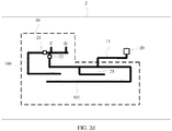
- FIG. 2d provides a schematic structural diagram of yet another antenna apparatus on the basis of the antenna apparatus 2 provided in FIG. 2a .
- one stub 25 is added to the antenna apparatus 2.
- the stub 25 is at a position with a maximum value of current distribution on a second branch 101 of a wavelength corresponding to a specified high frequency at which the antenna apparatus 2 works.
- a quantity of stubs may be determined according to actual requirements.
- FIG. 2b and FIG. 2c several stubs may be further added.
- a free end of the stub 25 in FIG. 2d may be connected to a filtering matching device, which is not drawn and described herein again.
- the free end of the stub 11 may be enabled to near the second branch 101, that is, may be bent towards the second branch 101.
- the length of the stub 11 is determined according to the specified high frequency, and in practice, an antenna apparatus works at a frequency band, and therefore, the enabling the free end of the stub 11 to near the second branch 101 can cancel a current distribution error caused because the antenna apparatus works at a frequency other than the specified high frequency, which is not drawn and described herein again.
- the antenna apparatus 2 provided in the embodiment of the present invention includes an antenna body 10 and a stub 11, where the antenna body 10 includes a first branch 100 used to radiate a high-frequency signal and a second branch 101 used to radiate a low-frequency signal; one end of the stub 11 is connected to a connection point of the second branch 101, and the other end of the stub 11 is a free end; the connection point is a position with a maximum value of current distribution on the second branch 101 of a wavelength corresponding to a specified high frequency at which the antenna apparatus works; and the length of the stub 11 is determined according to the wavelength corresponding to the specified high frequency.
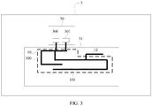
- FIG. 3 is a schematic structural diagram of a terminal according to Embodiment 3 of the present invention. As shown in FIG. 3 , the terminal 3 includes: a printed circuit board 30 and an antenna apparatus 31.
- a feeder 300 and a ground end 301 are disposed on the printed circuit board 30, and the antenna apparatus 31 may be any antenna apparatus described in Embodiment 1 and Embodiment 2.
- the antenna apparatus 31 being the antenna apparatus 1 in Embodiment 1 is used as an example, where a first branch 100 in the antenna apparatus 31 is connected to the feeder 300, and a second branch 101 is connected to the feeder 300; or a first branch 100 in the antenna apparatus is connected to the ground end 301, and a second branch 101 is connected to the feeder 300.
- the schematic structural diagram of the terminal 3 when the second branch 101 is connected to the feeder 300 is shown herein by only using the antenna apparatus 1 provided in FIG. 1 as an example. Neither another connection manner of the first branch 100 and the second branch 101, nor any one of other antenna apparatuses described in Embodiment 1 and Embodiment 2 is drawn or described again.
- the terminal 3 provided in the embodiment of the present invention includes an antenna body 10 and a stub 11, where the antenna body 10 includes a first branch 100 used to radiate a high-frequency signal and a second branch 101 used to radiate a low-frequency signal; one end of the stub 11 is connected to a connection point of the second branch 101, and the other end of the stub 11 is a free end; the connection point is a position with a maximum value of current distribution on the second branch 101 of a wavelength corresponding to a specified high frequency at which the antenna apparatus works; and the length of the stub 11 is determined according to the wavelength corresponding to the specified high frequency.
Landscapes
- Engineering & Computer Science (AREA)
- Computer Networks & Wireless Communication (AREA)
- Waveguide Aerials (AREA)
- Support Of Aerials (AREA)
- Details Of Aerials (AREA)
Abstract
Description
- The present invention relates to communications technologies, and in particular, to an antenna apparatus and a terminal.
- With commercial use of the 4th generation mobile communication technology (The 4 Generation Mobile Communication Technology, 4G for short), development of handheld mobile terminals more tends towards ultra-thinness, multi-function, large battery capacity, and the like, which imposes an increasingly higher requirement on antenna products of the mobile terminals.
- In technical solutions of Long Term Evolution (Long Term Evolution, LTE for short) antennas, one solution is that a planar inverted F antenna (Planar Inverted F Antenna, PIFA for short) evolving from a microstrip antenna having one short-circuited end is used as a terminal antenna. To cover more frequency bands, in the prior art, generally a parasitic branch may be added, that is, a quantity of branches used to radiate high-frequency signals may be increased, or the length of a branch used to radiate a low-frequency signal may be increased, so as to cover a corresponding high frequency by using a higher order mode of a low frequency.
- However, regardless of whether a parasitic branch is added or the length of a low-frequency branch is increased, the antenna has relatively poor performance when occupying relatively small terminal space.
- Embodiments of the present invention provide an antenna apparatus and a terminal, so as to resolve a problem in the prior art that a terminal antenna has relatively poor performance when occupying relatively small terminal space.
- According to a first aspect of the embodiments of the present invention, an antenna apparatus is provided, including: an antenna body and at least one stub, where the antenna body includes a first branch used to radiate a high-frequency signal and a second branch used to radiate a low-frequency signal; and
one end of the stub is connected to a connection point of the second branch, and the other end of the stub is a free end; the connection point is a position with a maximum value of current distribution on the second branch of a wavelength corresponding to a specified high frequency at which the antenna apparatus works; and the length of the stub is determined according to the wavelength corresponding to the specified high frequency. - In a first possible implementation manner, according to the first aspect, a first feeding connection end is disposed on the first branch, and a second feeding connection end is disposed on the second branch.
- In a second possible implementation manner, according to the first aspect, a ground connection end is disposed on the first branch, and a third feeding connection end is disposed on the second branch.
- In a third possible implementation manner, with reference to the first aspect, the first possible implementation manner, and the second possible implementation manner, the free end of the stub is near the second branch.
- In a fourth possible implementation manner, with reference to the first aspect, the first possible implementation manner, the second possible implementation manner, and the third possible implementation manner, the antenna apparatus further includes a filtering matching device connected to the free end of the stub.
- According to a second aspect of the embodiments of the present invention, a terminal is provided, including: a printed circuit board and any antenna apparatus according to the first aspect, where a feeder and a ground end are disposed on the printed circuit board; and the first branch in the antenna apparatus is connected to the feeder, and the second branch is connected to the feeder, or the first branch in the antenna apparatus is connected to the ground end, and the second branch is connected to the feeder.
- An antenna apparatus provided in an embodiment of the present invention includes an antenna body and at least one stub, where the antenna body includes a first branch used to radiate a high-frequency signal and a second branch used to radiate a low-frequency signal; one end of the stub is connected to a connection point of the second branch, and the other end of the stub is a free end; the connection point is a position with a maximum value of current distribution on the second branch of a wavelength corresponding to a specified high frequency at which the antenna apparatus works; and the length of the stub is determined according to the wavelength corresponding to the specified high frequency. As compared with a parasitic branch in the prior art, the foregoing stub occupies smaller space, and the foregoing stub can increase coverage bandwidth and efficiency of high frequencies and low frequencies of an antenna apparatus. Therefore, the antenna apparatus has better performance while occupying a relatively small area.
- To describe the technical solutions in the embodiments of the present invention or in the prior art more clearly, the following briefly describes the accompanying drawings required for describing the embodiments or the prior art. Apparently, the accompanying drawings in the following description show some embodiments of the present invention, and a person of ordinary skill in the art may still derive other drawings from these accompanying drawings without creative efforts.
-
FIG. 1 is a schematic structural diagram of an antenna apparatus according toEmbodiment 1 of the present invention; -
FIG. 2a is a schematic structural diagram of an antenna apparatus according toEmbodiment 2 of the present invention; -
FIG. 2b is a schematic structural diagram of another antenna apparatus according toEmbodiment 2 of the present invention; -
FIG. 2c is a schematic structural diagram of yet another antenna apparatus according toEmbodiment 2 of the present invention; -
FIG. 2d is a schematic structural diagram of yet another antenna apparatus according toEmbodiment 2 of the present invention; and -
FIG. 3 is a schematic structural diagram of a terminal according toEmbodiment 3 of the present invention. - To make the objectives, technical solutions, and advantages of the embodiments of the present invention clearer, the following clearly and completely describes the technical solutions in the embodiments of the present invention with reference to the accompanying drawings in the embodiments of the present invention. Apparently, the described embodiments are some but not all of the embodiments of the present invention. All other embodiments obtained by a person of ordinary skill in the art based on the embodiments of the present invention without creative efforts shall fall within the protection scope of the present invention.
-
FIG. 1 is a schematic structural diagram of an antenna apparatus according toEmbodiment 1 of the present invention. As shown inFIG. 1 , theantenna apparatus 1 includes anantenna body 10 and astub 11. - Specifically, the
antenna body 10 includes afirst branch 100 used to radiate a high-frequency signal and asecond branch 101 used to radiate a low-frequency signal. For example, in a practical application, the high-frequency signal may be a 3rd generation mobile communication technology (3rd-Generation, 3G for short) signal of 1.575 Giga Hertz (GHz) to 2.17 GHz, and the low-frequency signal may be a Global System for Mobile Communications (Global System for Mobile Communications, GSM for short) signal in a frequency range of 820 Mega Hertz (MHz) to 960 MHz. In practice, the foregoingfirst branch 100 may be several metal conducting wires that are shorter than thesecond branch 101; thesecond branch 101 may be several metal conducting wires that are longer than thefirst branch 100; and a quantity of the metal conducting wires forming thefirst branch 100 and a quantity of the metal conducting wires forming thesecond branch 101 are not limited herein. - Optionally, the
antenna body 10 may be an inverted F antenna (Inverted F Antenna, IFA for short), and in particular, theantenna body 10 may be a planar inverted F antenna (Plannar Inverted F Antenna, PIFA for short). - Further, the
antenna apparatus 1 limits a disposing position and the length of thestub 11. - Regarding the position, one end of the
stub 11 is connected to a connection point of thesecond branch 101, and the other end of thestub 11 is a free end. The foregoing connection point is a position with a maximum value of current distribution on thesecond branch 101 of a wavelength corresponding to a specified high frequency at which theantenna apparatus 1 works. For example, a product of a wavelength and a frequency is equal to the speed of light; therefore, after a specified high frequency is determined, a wavelength corresponding to the specified high frequency is determined by dividing the speed of light by the specified high frequency; and after the wavelength is determined, current distribution on thesecond branch 101 of an electromagnetic wave of the wavelength may be determined according to a feeding mode and boundary conditions of thestub 11, so as to determine a maximum value of the current distribution. - Regarding the length, the length of the
stub 11 is determined according to the wavelength corresponding to the specified high frequency. It can be known from the description in the previous paragraph that after the specified high frequency is determined, the wavelength corresponding to the specified high frequency is also determined. Moreover, the length of thestub 11, that is, the actual physical length of thestub 11, may generally equal a multiple of the wavelength, and the multiple is the electrical length. Specifically, the electrical length is a ratio of the actual physical length of thestub 11 to the wavelength corresponding to the specified high frequency, that is, is the actual physical length of thestub 11 divided by the wavelength corresponding to the specified high frequency at which theantenna apparatus 1 works. In practice, the electrical length of thestub 11 may be determined according to an area that needs to be covered by theantenna apparatus 1, space occupied by theantenna apparatus 1, impedance distribution of thestub 11, and the like. To ensure a coverage area and radiation efficiency of theantenna apparatus 1, the foregoing electrical length generally does not exceed 1/2, that is, the actual physical length of thestub 11 generally does not exceed 1/2 of the wavelength corresponding to the specified high frequency. For example, theforegoing stub 11 may be made into a dipole antenna whose electrical length is 1/4, that is, the actual physical length of thestub 11 is 1/4 of the wavelength corresponding to the specified high frequency. - In practice, the specified high frequency at which the
antenna apparatus 1 works may be determined according to a frequency band at which theantenna apparatus 1 needs to actually work, for example, a relatively low frequency in a high frequency band at which theantenna apparatus 1 works may be selected as the foregoing specified high frequency. - It shall be noted that the
antenna apparatus 1 including onestub 11 is only used as an example herein, but the present invention is not limited thereto. That is, after a specified high frequency is selected, the specified high frequency may correspond to a wavelength because a product of a wavelength and a frequency is equal to the speed of light. Moreover, after the wavelength is determined, a diagram of current distribution on thesecond branch 101 may be determined. There may be more than one maximum value of current distribution, and therefore, a quantity ofstubs 11 may be greater than one. The specific quantity of the stubs may be determined according to a frequency range that needs to be covered by theantenna apparatus 1 in practice. Besides, in practice, the material of thestub 11 is the same as the material for making an antenna in the prior art, such as, a copper plated material, or an alloy. Moreover, a direction that thestub 11 faces is not limited herein, that is, a position of thestub 11 relative to thefirst branch 100, that is, thestub 11 may be disposed at an external side of thefirst branch 100 or may be disposed at an internal side of thefirst branch 100. - How a
stub 11 improves performance of anantenna apparatus 1 is briefly described below. For a high-frequency signal, if there is only afirst branch 100, thefirst branch 100 produces resonance at only one high frequency band. After astub 11 is added to asecond branch 101 used to radiate a low frequency, thestub 11 may function to match radiation performed on a high frequency because thestub 11 may regulate high-frequency current distribution, so that thefirst branch 100 synchronously produces resonance at two high frequency bands. For example, if afirst branch 100 of anantenna apparatus 1 is designed to produce one high frequency, theantenna apparatus 1 may cover 1710 MHz to 2170 MHz, and if theantenna apparatus 1 needs to cover a higher frequency band, such as an LTE frequency band of 2300 MHz to 2700 MHz, the objective of covering the foregoing LTE frequency band may be achieved by adjusting the length of astub 11 and a position of thestub 11 on thesecond branch 101. Certainly, when more than onestub 11 is added, resonance may be produced at more high frequency bands. For a low-frequency signal, addition of astub 11 may directly increase radiation resistance at a low frequency. Moreover, thestub 11 can radiate the signal, so that a coverage area of a low-frequency electric field is expanded and low-frequency bandwidth and efficiency are increased. - It can be seen that in the
antenna apparatus 1 provided in the embodiment of the present invention, if the same bandwidth is to be covered, a solution of adding astub 11 relates to smaller occupied space as compared with a solution of adding a parasitic branch. If an occupied area in the solution of adding astub 11 is the same as an occupied area in the solution of adding a parasitic branch, the solution of adding astub 11 results in wider bandwidth coverage and higher antenna efficiency. Therefore, theantenna apparatus 1 provided in the embodiment of the present invention may provide better antenna performance while occupying a relatively small area. Moreover, as compared with an antenna with a switch, theantenna apparatus 1 provided in the embodiment of the present invention is low in design complexity, and antenna radiation efficiency is improved. -
FIG. 2a is a schematic structural diagram of an antenna apparatus according toEmbodiment 2 of the present invention. As shown inFIG. 2a , theantenna apparatus 2 includes: anantenna body 11, astub 11, and afiltering matching device 20. - Specifically, the
antenna body 10 includes afirst branch 100 used to radiate a high-frequency signal and asecond branch 101 used to radiate a low-frequency signal. A firstfeeding connection end 21 is disposed on thefirst branch 100, and a secondfeeding connection end 22 is disposed on thesecond branch 101. Both of the firstfeeding connection end 21 and the secondfeeding connection end 22 are configured to be connected to a feed (Feed), that is, F inFIG. 2a , of a feeder, and the feeder is configured to provide an input signal for theantenna apparatus 2. - Further, the
filtering matching device 20 is connected to a free end of thestub 11. Thefiltering matching device 20 is a low-cut high-pass filtering network determined according to a specified high frequency, and is configured to better match radiation that theantenna apparatus 1 performs on a high frequency. - Optionally, the length of the
stub 11 may be 1/4 of a wavelength corresponding to the specified high frequency. Certainly, in practice, the length of thestub 11 is generally selected to be near 1/4 of the wavelength corresponding to the specified high frequency at which theantenna apparatus 1 works. - Optionally, the
antenna body 10 may be an inverted F antenna (Inverted F Antenna, IFA for short), and in particular, theantenna body 10 may be a planar inverted F antenna (Plannar Inverted F Antenna, PIFA for short). - Certainly, in
FIG. 2a , both of thefirst branch 100 and thesecond branch 101 are connected to and extend from the feeder. In practice, thefirst branch 100 and thesecond branch 101 may be respectively connected to the feed F of the feeder and a ground end G (Ground), that is, G inFIG. 2a , of a terminal at which theantenna apparatus 2 is located.FIG. 2b is a schematic structural diagram of another antenna apparatus according toEmbodiment 2 of the present invention. As shown inFIG. 2b , aground connection end 23 is disposed on afirst branch 100 of theantenna apparatus 2, and a thirdfeeding connection end 24 is disposed on asecond branch 101. Theground connection end 23 is connected to a ground end G of the terminal at which theantenna apparatus 2 is located, and the thirdfeeding connection end 24 is connected to a feed of a feeder. Certainly, an antenna apparatus similar to the antenna apparatus ofFIG. 2b may have a structure shown inFIG. 2c .FIG. 2b andFIG. 2c only differ in bending directions of stubs. In practice, a corresponding structure may be selected according to an actual situation, and details are not described herein again. - Besides, in
FIG. 2a to FIG. 2c , description is made by using onestub 11 as an example. In practice, there may be several stubs.FIG. 2d provides a schematic structural diagram of yet another antenna apparatus on the basis of theantenna apparatus 2 provided inFIG. 2a . As compared withFIG. 2a , onestub 25 is added to theantenna apparatus 2. Certainly, thestub 25 is at a position with a maximum value of current distribution on asecond branch 101 of a wavelength corresponding to a specified high frequency at which theantenna apparatus 2 works. Just as described inEmbodiment 1, in practice, a quantity of stubs may be determined according to actual requirements. InFIG. 2b andFIG. 2c , several stubs may be further added. In addition, a free end of thestub 25 inFIG. 2d may be connected to a filtering matching device, which is not drawn and described herein again. - Besides, in
FIG. 2a to FIG. 2d , the free end of thestub 11 may be enabled to near thesecond branch 101, that is, may be bent towards thesecond branch 101. Just as described inEmbodiment 1, the length of thestub 11 is determined according to the specified high frequency, and in practice, an antenna apparatus works at a frequency band, and therefore, the enabling the free end of thestub 11 to near thesecond branch 101 can cancel a current distribution error caused because the antenna apparatus works at a frequency other than the specified high frequency, which is not drawn and described herein again. - The
antenna apparatus 2 provided in the embodiment of the present invention includes anantenna body 10 and astub 11, where theantenna body 10 includes afirst branch 100 used to radiate a high-frequency signal and asecond branch 101 used to radiate a low-frequency signal; one end of thestub 11 is connected to a connection point of thesecond branch 101, and the other end of thestub 11 is a free end; the connection point is a position with a maximum value of current distribution on thesecond branch 101 of a wavelength corresponding to a specified high frequency at which the antenna apparatus works; and the length of thestub 11 is determined according to the wavelength corresponding to the specified high frequency. By means of the technical solution provided in the embodiment of the present invention, antenna performance can be improved while occupying relatively small space. -
FIG. 3 is a schematic structural diagram of a terminal according toEmbodiment 3 of the present invention. As shown inFIG. 3 , theterminal 3 includes: a printedcircuit board 30 and anantenna apparatus 31. - Specifically, a
feeder 300 and aground end 301 are disposed on the printedcircuit board 30, and theantenna apparatus 31 may be any antenna apparatus described inEmbodiment 1 andEmbodiment 2. Theantenna apparatus 31 being theantenna apparatus 1 inEmbodiment 1 is used as an example, where afirst branch 100 in theantenna apparatus 31 is connected to thefeeder 300, and asecond branch 101 is connected to thefeeder 300; or afirst branch 100 in the antenna apparatus is connected to theground end 301, and asecond branch 101 is connected to thefeeder 300. The schematic structural diagram of theterminal 3 when thesecond branch 101 is connected to thefeeder 300 is shown herein by only using theantenna apparatus 1 provided inFIG. 1 as an example. Neither another connection manner of thefirst branch 100 and thesecond branch 101, nor any one of other antenna apparatuses described inEmbodiment 1 andEmbodiment 2 is drawn or described again. - The
terminal 3 provided in the embodiment of the present invention includes anantenna body 10 and astub 11, where theantenna body 10 includes afirst branch 100 used to radiate a high-frequency signal and asecond branch 101 used to radiate a low-frequency signal; one end of thestub 11 is connected to a connection point of thesecond branch 101, and the other end of thestub 11 is a free end; the connection point is a position with a maximum value of current distribution on thesecond branch 101 of a wavelength corresponding to a specified high frequency at which the antenna apparatus works; and the length of thestub 11 is determined according to the wavelength corresponding to the specified high frequency. By means of the technical solution provided in the embodiment of the present invention, antenna performance can be improved while occupying relatively small space. - Further embodiments of the present invention are provided in the following. It should be noted that the numbering used in the following section does not necessarily need to comply with the numbering used in the previous sections.
-
Embodiment 1. An antenna apparatus, comprising: an antenna body and at least one stub, wherein the antenna body comprises a first branch used to radiate a high-frequency signal and a second branch used to radiate a low-frequency signal; and
one end of the stub is connected to a connection point of the second branch, and the other end of the stub is a free end; the connection point is a position with a maximum value of current distribution on the second branch of a wavelength corresponding to a specified high frequency at which the antenna apparatus works; and the length of the stub is determined according to the wavelength corresponding to the specified high frequency. -
Embodiment 2. The antenna apparatus according toembodiment 1, wherein a first feeding connection end is disposed on the first branch, and a second feeding connection end is disposed on the second branch. -
Embodiment 3. The antenna according toembodiment 1, wherein a ground connection end is disposed on the first branch, and a third feeding connection end is disposed on the second branch. - Embodiment 4. The antenna apparatus according to any one of
embodiments 1 to 3, wherein the free end of the stub is near the second branch. - Embodiment 5. The antenna apparatus according to any one of
embodiments 1 to 4, further comprising: a filtering matching device connected to the free end of the stub. - Embodiment 6. The antenna apparatus according to embodiment 5, wherein the filtering matching device is a low-cut high-pass filtering network determined according to the specified high frequency.
- Embodiment 7. The antenna apparatus according to any one of
embodiments 1 to 6, wherein the length of the stub is 1/4 of the wavelength corresponding to the specified high frequency. - Embodiment 8. The antenna apparatus according to any one of
embodiments 1 to 7, wherein the antenna body is an inverted F antenna IFA. - Embodiment 9. A terminal, comprising: a printed circuit board and the antenna apparatus according to any one of
claims 1 to 8, wherein a feeder and a ground end are disposed on the printed circuit board; and the first branch in the antenna apparatus is connected to the feeder, and the second branch is connected to the feeder, or the first branch in the antenna apparatus is connected to the ground end, and the second branch is connected to the feeder. - Finally, it should be noted that the foregoing embodiments are merely intended for describing the technical solutions of the present invention, but not for limiting the present invention. Although the present invention is described in detail with reference to the foregoing embodiments, persons of ordinary skill in the art should understand that they may still make modifications to the technical solutions described in the foregoing embodiments or make equivalent replacements to some or all technical features thereof, without departing from the scope of the technical solutions of the embodiments of the present invention.
Claims (12)
- An antenna apparatus (1), comprising: an antenna body (10) and at least one radiating element (11), wherein the antenna body comprises a first branch (100) configured to radiate a high-frequency signal and a second branch (101) configured to radiate a low-frequency signal; and
one end of the radiating element is connected to a connection point of the second branch, and the other end of the radiating element is a free end; the connection point is a position with a maximum value of current distribution on the second branch of a wavelength corresponding to a specified high frequency at which the antenna apparatus is configured to work; and the length of the radiating element is determined according to the wavelength corresponding to the specified high frequency;
wherein a first feeding connection end is disposed on the first branch (100), and a second feeding connection end is disposed on the second branch (101). - The antenna apparatus (1) according to claim 1, wherein the apparatus (1) further comprising a feed (F), the first feeding connection end and the second feeding connection end being configured to be connected to said feed (F).
- The antenna apparatus (1) according to claim 1, wherein a ground connection end is disposed on the first branch, and a third feeding connection end is disposed on the second branch.
- The antenna apparatus (1) according to any one of claims 1 to 3, wherein the free end of the radiating element is near the second branch (101).
- The antenna apparatus (1) according to any one of claims 1 to 4, wherein the length of the radiating element is 1/4 of the wavelength corresponding to the specified high frequency.
- The antenna apparatus (1) according to any one of claims 1 to 5, wherein the antenna body (10) is an inverted F antenna IFA.
- The antenna apparatus (1) according to any one of claims 1 to 6, wherein the first branch (100) are several metal conducting wires that are shorter than the second branch (101); the second branch 101 are several metal conducting wires that are longer than the first branch (100).
- The antenna apparatus (1) according to any one of claims 1 to 7, wherein the material of the at least one radiating element (11) is a copper plated material, or an alloy.
- The antenna apparatus (1) according to any one of claims 1 to 8, wherein a position of the at least one radiating element (11) is disposed at an external side of the first branch (100) or is disposed at an internal side of the first branch (100).
- A terminal, comprising: a printed circuit board and the antenna apparatus (1) according to any one of claims 1 to 9.
- The terminal according to claim 10, wherein a feeder and a ground end are disposed on the printed circuit board; and the first branch (100) in the antenna apparatus is connected to the feeder, and the second branch (101) is connected to the feeder.
- The terminal according to claim 10, wherein a feeder and a ground end are disposed on the printed circuit board, the first branch (100) in the antenna apparatus is connected to the ground end, and the second branch (101) is connected to the feeder.
Priority Applications (1)
| Application Number | Priority Date | Filing Date | Title |
|---|---|---|---|
| EP20194733.0A EP3828996B1 (en) | 2014-04-28 | 2014-04-28 | Antenna apparatus and terminal |
Applications Claiming Priority (3)
| Application Number | Priority Date | Filing Date | Title |
|---|---|---|---|
| PCT/CN2014/076386 WO2015165007A1 (en) | 2014-04-28 | 2014-04-28 | Antenna apparatus and terminal |
| EP14890777.7A EP3121899B1 (en) | 2014-04-28 | 2014-04-28 | Antenna apparatus and terminal |
| EP20194733.0A EP3828996B1 (en) | 2014-04-28 | 2014-04-28 | Antenna apparatus and terminal |
Related Parent Applications (2)
| Application Number | Title | Priority Date | Filing Date |
|---|---|---|---|
| EP14890777.7A Division EP3121899B1 (en) | 2014-04-28 | 2014-04-28 | Antenna apparatus and terminal |
| EP14890777.7A Division-Into EP3121899B1 (en) | 2014-04-28 | 2014-04-28 | Antenna apparatus and terminal |
Publications (2)
| Publication Number | Publication Date |
|---|---|
| EP3828996A1 true EP3828996A1 (en) | 2021-06-02 |
| EP3828996B1 EP3828996B1 (en) | 2023-08-02 |
Family
ID=54357975
Family Applications (2)
| Application Number | Title | Priority Date | Filing Date |
|---|---|---|---|
| EP20194733.0A Active EP3828996B1 (en) | 2014-04-28 | 2014-04-28 | Antenna apparatus and terminal |
| EP14890777.7A Active EP3121899B1 (en) | 2014-04-28 | 2014-04-28 | Antenna apparatus and terminal |
Family Applications After (1)
| Application Number | Title | Priority Date | Filing Date |
|---|---|---|---|
| EP14890777.7A Active EP3121899B1 (en) | 2014-04-28 | 2014-04-28 | Antenna apparatus and terminal |
Country Status (6)
| Country | Link |
|---|---|
| US (1) | US9991585B2 (en) |
| EP (2) | EP3828996B1 (en) |
| JP (1) | JP6272505B2 (en) |
| KR (1) | KR101867444B1 (en) |
| CN (1) | CN105409058B (en) |
| WO (1) | WO2015165007A1 (en) |
Families Citing this family (7)
| Publication number | Priority date | Publication date | Assignee | Title |
|---|---|---|---|---|
| KR102506711B1 (en) * | 2015-11-02 | 2023-03-08 | 삼성전자주식회사 | Antenna structure and electronic device comprising thereof |
| EP3386030B1 (en) * | 2015-12-31 | 2022-08-10 | Huawei Technologies Co., Ltd. | Antenna apparatus and terminal |
| US11211697B2 (en) * | 2017-10-12 | 2021-12-28 | TE Connectivity Services Gmbh | Antenna apparatus |
| CN108281770B (en) * | 2018-03-05 | 2024-09-27 | 上海煜鹏通讯电子股份有限公司 | Ultra-wideband antenna and resonance method thereof |
| CN109687105B (en) * | 2018-12-21 | 2020-10-13 | 惠州Tcl移动通信有限公司 | Electronic equipment |
| CN114788090B (en) * | 2019-12-19 | 2025-09-26 | 华为技术有限公司 | Antenna device and base station |
| CN116264350A (en) * | 2021-12-15 | 2023-06-16 | 华为技术有限公司 | Antennas and Electronics |
Citations (3)
| Publication number | Priority date | Publication date | Assignee | Title |
|---|---|---|---|---|
| US5406295A (en) * | 1992-02-26 | 1995-04-11 | Flachglas Aktiengesellschaft | Window antenna for a motor vehicle body |
| US20040222923A1 (en) * | 2003-05-07 | 2004-11-11 | Agere Systems, Incorporated | Dual-band antenna for a wireless local area network device |
| US20130285870A1 (en) * | 2012-04-26 | 2013-10-31 | Kabushiki Kaisha Toshiba | Antenna apparatus and electronic device including antenna apparatus |
Family Cites Families (30)
| Publication number | Priority date | Publication date | Assignee | Title |
|---|---|---|---|---|
| JP2712991B2 (en) | 1991-09-26 | 1998-02-16 | 三菱電機株式会社 | Antenna device |
| ATE330339T1 (en) * | 2001-10-11 | 2006-07-15 | Taiyo Yuden Kk | DIELECTRIC ANTENNA |
| JP2004096464A (en) * | 2002-08-30 | 2004-03-25 | Anten Corp | Frequency sharing antenna |
| JP2004112397A (en) * | 2002-09-19 | 2004-04-08 | Yokohama Tlo Co Ltd | Multi-frequency shared antenna and multi-band transmitter-receiver |
| US6965346B2 (en) * | 2002-12-16 | 2005-11-15 | Samsung Electro-Mechanics Co., Ltd. | Wireless LAN antenna and wireless LAN card with the same |
| JP2005167730A (en) * | 2003-12-03 | 2005-06-23 | Hitachi Cable Ltd | Multi-frequency antenna and information terminal device having the same |
| KR100666113B1 (en) * | 2003-12-13 | 2007-01-09 | 학교법인 한국정보통신학원 | Internal Multi-Band Antenna with Multiple Layers |
| WO2005062422A1 (en) * | 2003-12-23 | 2005-07-07 | Macquarie University | Multi-band, broadband, fully-planar antennas |
| TWI229473B (en) * | 2004-01-30 | 2005-03-11 | Yageo Corp | Dual-band inverted-F antenna with shorted parasitic elements |
| US7012573B2 (en) * | 2004-02-20 | 2006-03-14 | Samsung Electronics Co., Ltd. | Wide band antenna |
| JP2005311655A (en) * | 2004-04-21 | 2005-11-04 | Matsushita Electric Ind Co Ltd | Antenna device |
| JP2006165608A (en) * | 2004-12-02 | 2006-06-22 | Hitachi Cable Ltd | Small internal antenna |
| JP4308786B2 (en) * | 2005-02-24 | 2009-08-05 | パナソニック株式会社 | Portable radio |
| WO2006129239A1 (en) * | 2005-05-31 | 2006-12-07 | Nxp B.V. | Planar antenna assembly with impedance matching and reduced user interaction, for a rf communication equipment. |
| US7321341B2 (en) * | 2005-06-23 | 2008-01-22 | Center For Remote Sensing, Inc. | Compact broadband antenna with constant radiation pattern |
| TW200729611A (en) * | 2006-01-20 | 2007-08-01 | Advanced Connectek Inc | Multi-frequency antenna with wide-band function |
| KR100724434B1 (en) | 2006-04-18 | 2007-06-04 | 엘지전자 주식회사 | Multi-band antenna device and mobile communication terminal having same |
| JP2009253886A (en) * | 2008-04-10 | 2009-10-29 | Panasonic Corp | Antenna |
| JP5170233B2 (en) * | 2008-07-17 | 2013-03-27 | 株式会社村田製作所 | Double resonance antenna |
| CN101651256B (en) * | 2008-08-13 | 2013-08-07 | 深圳富泰宏精密工业有限公司 | Tri-band antenna |
| JP5435338B2 (en) * | 2009-06-15 | 2014-03-05 | 日立金属株式会社 | Multiband antenna |
| US8587491B2 (en) * | 2009-07-17 | 2013-11-19 | Blackberry Limited | Antenna with a C-shaped slot nested within an L-shaped slot and mobile device employing the antenna |
| JP2011176653A (en) * | 2010-02-25 | 2011-09-08 | Fujitsu Component Ltd | Antenna device |
| JP4991917B2 (en) * | 2010-07-30 | 2012-08-08 | 株式会社東芝 | Antenna device |
| TWI487198B (en) * | 2011-06-03 | 2015-06-01 | Wistron Neweb Corp | A multi-band antenna |
| KR101257093B1 (en) * | 2011-06-10 | 2013-04-19 | 엘지전자 주식회사 | Mobile terminal |
| JP2013017112A (en) * | 2011-07-06 | 2013-01-24 | Hitachi Metals Ltd | Antenna and radio communication device using the same |
| TWI484698B (en) | 2011-08-29 | 2015-05-11 | Univ Nat Chiao Tung | Printed filtering antenna |
| TWI578616B (en) * | 2013-04-02 | 2017-04-11 | 群邁通訊股份有限公司 | Antenna structure and wireless communication device using same |
| WO2015013880A1 (en) | 2013-07-30 | 2015-02-05 | 华为终端有限公司 | Wireless terminal |
-
2014
- 2014-04-28 WO PCT/CN2014/076386 patent/WO2015165007A1/en not_active Ceased
- 2014-04-28 US US15/307,316 patent/US9991585B2/en active Active
- 2014-04-28 JP JP2016564570A patent/JP6272505B2/en active Active
- 2014-04-28 CN CN201480041099.8A patent/CN105409058B/en active Active
- 2014-04-28 EP EP20194733.0A patent/EP3828996B1/en active Active
- 2014-04-28 KR KR1020167031475A patent/KR101867444B1/en not_active Expired - Fee Related
- 2014-04-28 EP EP14890777.7A patent/EP3121899B1/en active Active
Patent Citations (3)
| Publication number | Priority date | Publication date | Assignee | Title |
|---|---|---|---|---|
| US5406295A (en) * | 1992-02-26 | 1995-04-11 | Flachglas Aktiengesellschaft | Window antenna for a motor vehicle body |
| US20040222923A1 (en) * | 2003-05-07 | 2004-11-11 | Agere Systems, Incorporated | Dual-band antenna for a wireless local area network device |
| US20130285870A1 (en) * | 2012-04-26 | 2013-10-31 | Kabushiki Kaisha Toshiba | Antenna apparatus and electronic device including antenna apparatus |
Also Published As
| Publication number | Publication date |
|---|---|
| KR101867444B1 (en) | 2018-06-14 |
| EP3121899A4 (en) | 2017-04-05 |
| CN105409058B (en) | 2018-08-14 |
| JP6272505B2 (en) | 2018-01-31 |
| EP3121899A1 (en) | 2017-01-25 |
| EP3121899B1 (en) | 2020-11-18 |
| US9991585B2 (en) | 2018-06-05 |
| CN105409058A (en) | 2016-03-16 |
| KR20160140952A (en) | 2016-12-07 |
| EP3828996B1 (en) | 2023-08-02 |
| US20170047642A1 (en) | 2017-02-16 |
| JP2017514403A (en) | 2017-06-01 |
| WO2015165007A1 (en) | 2015-11-05 |
Similar Documents
| Publication | Publication Date | Title |
|---|---|---|
| US10819031B2 (en) | Printed circuit board antenna and terminal | |
| JP7103556B2 (en) | Antenna system and terminal device | |
| US9991585B2 (en) | Antenna apparatus and terminal | |
| TWI624999B (en) | Atnenna structure and wireless communiation device employing same | |
| US11355853B2 (en) | Antenna structure and wireless communication device using the same | |
| EP2851997A1 (en) | Printed circuit board antenna and printed circuit board | |
| CN105742812A (en) | Mobile terminal and antenna structure thereof | |
| CN110970709B (en) | Antenna structure and wireless communication device with same | |
| US10014574B2 (en) | Antenna device | |
| US10109926B2 (en) | Antenna radiator, antenna and mobile terminal | |
| CN105655690B (en) | A kind of frequency range switched antenna | |
| WO2015120780A1 (en) | Antenna and mobile terminal | |
| CN107834206B (en) | Antenna and mobile terminal | |
| CN108432048A (en) | A slot antenna and terminal | |
| US20170271773A1 (en) | Electrically tunable miniature antenna | |
| CN104143694B (en) | Antenna structure and wireless communication device using same | |
| JP7243966B2 (en) | Antenna system and terminal device | |
| US20180233811A1 (en) | Antenna | |
| CN114069227A (en) | Multi-band antenna |
Legal Events
| Date | Code | Title | Description |
|---|---|---|---|
| PUAI | Public reference made under article 153(3) epc to a published international application that has entered the european phase |
Free format text: ORIGINAL CODE: 0009012 |
|
| STAA | Information on the status of an ep patent application or granted ep patent |
Free format text: STATUS: THE APPLICATION HAS BEEN PUBLISHED |
|
| AC | Divisional application: reference to earlier application |
Ref document number: 3121899 Country of ref document: EP Kind code of ref document: P |
|
| AK | Designated contracting states |
Kind code of ref document: A1 Designated state(s): AL AT BE BG CH CY CZ DE DK EE ES FI FR GB GR HR HU IE IS IT LI LT LU LV MC MK MT NL NO PL PT RO RS SE SI SK SM TR |
|
| RAP1 | Party data changed (applicant data changed or rights of an application transferred) |
Owner name: HONOR DEVICE CO., LTD. |
|
| STAA | Information on the status of an ep patent application or granted ep patent |
Free format text: STATUS: REQUEST FOR EXAMINATION WAS MADE |
|
| 17P | Request for examination filed |
Effective date: 20211110 |
|
| RBV | Designated contracting states (corrected) |
Designated state(s): AL AT BE BG CH CY CZ DE DK EE ES FI FR GB GR HR HU IE IS IT LI LT LU LV MC MK MT NL NO PL PT RO RS SE SI SK SM TR |
|
| STAA | Information on the status of an ep patent application or granted ep patent |
Free format text: STATUS: EXAMINATION IS IN PROGRESS |
|
| 17Q | First examination report despatched |
Effective date: 20220301 |
|
| GRAP | Despatch of communication of intention to grant a patent |
Free format text: ORIGINAL CODE: EPIDOSNIGR1 |
|
| STAA | Information on the status of an ep patent application or granted ep patent |
Free format text: STATUS: GRANT OF PATENT IS INTENDED |
|
| INTG | Intention to grant announced |
Effective date: 20230301 |
|
| GRAS | Grant fee paid |
Free format text: ORIGINAL CODE: EPIDOSNIGR3 |
|
| GRAA | (expected) grant |
Free format text: ORIGINAL CODE: 0009210 |
|
| STAA | Information on the status of an ep patent application or granted ep patent |
Free format text: STATUS: THE PATENT HAS BEEN GRANTED |
|
| AC | Divisional application: reference to earlier application |
Ref document number: 3121899 Country of ref document: EP Kind code of ref document: P |
|
| AK | Designated contracting states |
Kind code of ref document: B1 Designated state(s): AL AT BE BG CH CY CZ DE DK EE ES FI FR GB GR HR HU IE IS IT LI LT LU LV MC MK MT NL NO PL PT RO RS SE SI SK SM TR |
|
| REG | Reference to a national code |
Ref country code: GB Ref legal event code: FG4D |
|
| REG | Reference to a national code |
Ref country code: CH Ref legal event code: EP |
|
| REG | Reference to a national code |
Ref country code: DE Ref legal event code: R096 Ref document number: 602014087882 Country of ref document: DE |
|
| REG | Reference to a national code |
Ref country code: IE Ref legal event code: FG4D |
|
| REG | Reference to a national code |
Ref country code: NL Ref legal event code: FP |
|
| REG | Reference to a national code |
Ref country code: LT Ref legal event code: MG9D |
|
| REG | Reference to a national code |
Ref country code: AT Ref legal event code: MK05 Ref document number: 1595876 Country of ref document: AT Kind code of ref document: T Effective date: 20230802 |
|
| PG25 | Lapsed in a contracting state [announced via postgrant information from national office to epo] |
Ref country code: GR Free format text: LAPSE BECAUSE OF FAILURE TO SUBMIT A TRANSLATION OF THE DESCRIPTION OR TO PAY THE FEE WITHIN THE PRESCRIBED TIME-LIMIT Effective date: 20231103 |
|
| PG25 | Lapsed in a contracting state [announced via postgrant information from national office to epo] |
Ref country code: IS Free format text: LAPSE BECAUSE OF FAILURE TO SUBMIT A TRANSLATION OF THE DESCRIPTION OR TO PAY THE FEE WITHIN THE PRESCRIBED TIME-LIMIT Effective date: 20231202 |
|
| PG25 | Lapsed in a contracting state [announced via postgrant information from national office to epo] |
Ref country code: SE Free format text: LAPSE BECAUSE OF FAILURE TO SUBMIT A TRANSLATION OF THE DESCRIPTION OR TO PAY THE FEE WITHIN THE PRESCRIBED TIME-LIMIT Effective date: 20230802 Ref country code: RS Free format text: LAPSE BECAUSE OF FAILURE TO SUBMIT A TRANSLATION OF THE DESCRIPTION OR TO PAY THE FEE WITHIN THE PRESCRIBED TIME-LIMIT Effective date: 20230802 Ref country code: PT Free format text: LAPSE BECAUSE OF FAILURE TO SUBMIT A TRANSLATION OF THE DESCRIPTION OR TO PAY THE FEE WITHIN THE PRESCRIBED TIME-LIMIT Effective date: 20231204 Ref country code: NO Free format text: LAPSE BECAUSE OF FAILURE TO SUBMIT A TRANSLATION OF THE DESCRIPTION OR TO PAY THE FEE WITHIN THE PRESCRIBED TIME-LIMIT Effective date: 20231102 Ref country code: LV Free format text: LAPSE BECAUSE OF FAILURE TO SUBMIT A TRANSLATION OF THE DESCRIPTION OR TO PAY THE FEE WITHIN THE PRESCRIBED TIME-LIMIT Effective date: 20230802 Ref country code: LT Free format text: LAPSE BECAUSE OF FAILURE TO SUBMIT A TRANSLATION OF THE DESCRIPTION OR TO PAY THE FEE WITHIN THE PRESCRIBED TIME-LIMIT Effective date: 20230802 Ref country code: IS Free format text: LAPSE BECAUSE OF FAILURE TO SUBMIT A TRANSLATION OF THE DESCRIPTION OR TO PAY THE FEE WITHIN THE PRESCRIBED TIME-LIMIT Effective date: 20231202 Ref country code: HR Free format text: LAPSE BECAUSE OF FAILURE TO SUBMIT A TRANSLATION OF THE DESCRIPTION OR TO PAY THE FEE WITHIN THE PRESCRIBED TIME-LIMIT Effective date: 20230802 Ref country code: GR Free format text: LAPSE BECAUSE OF FAILURE TO SUBMIT A TRANSLATION OF THE DESCRIPTION OR TO PAY THE FEE WITHIN THE PRESCRIBED TIME-LIMIT Effective date: 20231103 Ref country code: FI Free format text: LAPSE BECAUSE OF FAILURE TO SUBMIT A TRANSLATION OF THE DESCRIPTION OR TO PAY THE FEE WITHIN THE PRESCRIBED TIME-LIMIT Effective date: 20230802 Ref country code: AT Free format text: LAPSE BECAUSE OF FAILURE TO SUBMIT A TRANSLATION OF THE DESCRIPTION OR TO PAY THE FEE WITHIN THE PRESCRIBED TIME-LIMIT Effective date: 20230802 |
|
| PG25 | Lapsed in a contracting state [announced via postgrant information from national office to epo] |
Ref country code: PL Free format text: LAPSE BECAUSE OF FAILURE TO SUBMIT A TRANSLATION OF THE DESCRIPTION OR TO PAY THE FEE WITHIN THE PRESCRIBED TIME-LIMIT Effective date: 20230802 |
|
| PG25 | Lapsed in a contracting state [announced via postgrant information from national office to epo] |
Ref country code: ES Free format text: LAPSE BECAUSE OF FAILURE TO SUBMIT A TRANSLATION OF THE DESCRIPTION OR TO PAY THE FEE WITHIN THE PRESCRIBED TIME-LIMIT Effective date: 20230802 |
|
| PG25 | Lapsed in a contracting state [announced via postgrant information from national office to epo] |
Ref country code: SM Free format text: LAPSE BECAUSE OF FAILURE TO SUBMIT A TRANSLATION OF THE DESCRIPTION OR TO PAY THE FEE WITHIN THE PRESCRIBED TIME-LIMIT Effective date: 20230802 Ref country code: RO Free format text: LAPSE BECAUSE OF FAILURE TO SUBMIT A TRANSLATION OF THE DESCRIPTION OR TO PAY THE FEE WITHIN THE PRESCRIBED TIME-LIMIT Effective date: 20230802 Ref country code: ES Free format text: LAPSE BECAUSE OF FAILURE TO SUBMIT A TRANSLATION OF THE DESCRIPTION OR TO PAY THE FEE WITHIN THE PRESCRIBED TIME-LIMIT Effective date: 20230802 Ref country code: EE Free format text: LAPSE BECAUSE OF FAILURE TO SUBMIT A TRANSLATION OF THE DESCRIPTION OR TO PAY THE FEE WITHIN THE PRESCRIBED TIME-LIMIT Effective date: 20230802 Ref country code: DK Free format text: LAPSE BECAUSE OF FAILURE TO SUBMIT A TRANSLATION OF THE DESCRIPTION OR TO PAY THE FEE WITHIN THE PRESCRIBED TIME-LIMIT Effective date: 20230802 Ref country code: CZ Free format text: LAPSE BECAUSE OF FAILURE TO SUBMIT A TRANSLATION OF THE DESCRIPTION OR TO PAY THE FEE WITHIN THE PRESCRIBED TIME-LIMIT Effective date: 20230802 Ref country code: SK Free format text: LAPSE BECAUSE OF FAILURE TO SUBMIT A TRANSLATION OF THE DESCRIPTION OR TO PAY THE FEE WITHIN THE PRESCRIBED TIME-LIMIT Effective date: 20230802 |
|
| REG | Reference to a national code |
Ref country code: DE Ref legal event code: R097 Ref document number: 602014087882 Country of ref document: DE |
|
| PG25 | Lapsed in a contracting state [announced via postgrant information from national office to epo] |
Ref country code: IT Free format text: LAPSE BECAUSE OF FAILURE TO SUBMIT A TRANSLATION OF THE DESCRIPTION OR TO PAY THE FEE WITHIN THE PRESCRIBED TIME-LIMIT Effective date: 20230802 |
|
| PLBE | No opposition filed within time limit |
Free format text: ORIGINAL CODE: 0009261 |
|
| STAA | Information on the status of an ep patent application or granted ep patent |
Free format text: STATUS: NO OPPOSITION FILED WITHIN TIME LIMIT |
|
| 26N | No opposition filed |
Effective date: 20240503 |
|
| PG25 | Lapsed in a contracting state [announced via postgrant information from national office to epo] |
Ref country code: SI Free format text: LAPSE BECAUSE OF FAILURE TO SUBMIT A TRANSLATION OF THE DESCRIPTION OR TO PAY THE FEE WITHIN THE PRESCRIBED TIME-LIMIT Effective date: 20230802 |
|
| PG25 | Lapsed in a contracting state [announced via postgrant information from national office to epo] |
Ref country code: BG Free format text: LAPSE BECAUSE OF FAILURE TO SUBMIT A TRANSLATION OF THE DESCRIPTION OR TO PAY THE FEE WITHIN THE PRESCRIBED TIME-LIMIT Effective date: 20230802 |
|
| PG25 | Lapsed in a contracting state [announced via postgrant information from national office to epo] |
Ref country code: MC Free format text: LAPSE BECAUSE OF FAILURE TO SUBMIT A TRANSLATION OF THE DESCRIPTION OR TO PAY THE FEE WITHIN THE PRESCRIBED TIME-LIMIT Effective date: 20230802 |
|
| PG25 | Lapsed in a contracting state [announced via postgrant information from national office to epo] |
Ref country code: MC Free format text: LAPSE BECAUSE OF FAILURE TO SUBMIT A TRANSLATION OF THE DESCRIPTION OR TO PAY THE FEE WITHIN THE PRESCRIBED TIME-LIMIT Effective date: 20230802 Ref country code: BG Free format text: LAPSE BECAUSE OF FAILURE TO SUBMIT A TRANSLATION OF THE DESCRIPTION OR TO PAY THE FEE WITHIN THE PRESCRIBED TIME-LIMIT Effective date: 20230802 |
|
| REG | Reference to a national code |
Ref country code: CH Ref legal event code: PL |
|
| PG25 | Lapsed in a contracting state [announced via postgrant information from national office to epo] |
Ref country code: LU Free format text: LAPSE BECAUSE OF NON-PAYMENT OF DUE FEES Effective date: 20240428 |
|
| REG | Reference to a national code |
Ref country code: BE Ref legal event code: MM Effective date: 20240430 |
|
| PG25 | Lapsed in a contracting state [announced via postgrant information from national office to epo] |
Ref country code: LU Free format text: LAPSE BECAUSE OF NON-PAYMENT OF DUE FEES Effective date: 20240428 |
|
| PG25 | Lapsed in a contracting state [announced via postgrant information from national office to epo] |
Ref country code: BE Free format text: LAPSE BECAUSE OF NON-PAYMENT OF DUE FEES Effective date: 20240430 |
|
| PG25 | Lapsed in a contracting state [announced via postgrant information from national office to epo] |
Ref country code: FR Free format text: LAPSE BECAUSE OF NON-PAYMENT OF DUE FEES Effective date: 20240430 |
|
| PG25 | Lapsed in a contracting state [announced via postgrant information from national office to epo] |
Ref country code: FR Free format text: LAPSE BECAUSE OF NON-PAYMENT OF DUE FEES Effective date: 20240430 Ref country code: BE Free format text: LAPSE BECAUSE OF NON-PAYMENT OF DUE FEES Effective date: 20240430 Ref country code: CH Free format text: LAPSE BECAUSE OF NON-PAYMENT OF DUE FEES Effective date: 20240430 |
|
| PG25 | Lapsed in a contracting state [announced via postgrant information from national office to epo] |
Ref country code: IE Free format text: LAPSE BECAUSE OF NON-PAYMENT OF DUE FEES Effective date: 20240428 |
|
| PGFP | Annual fee paid to national office [announced via postgrant information from national office to epo] |
Ref country code: DE Payment date: 20250305 Year of fee payment: 12 |
|
| PG25 | Lapsed in a contracting state [announced via postgrant information from national office to epo] |
Ref country code: CY Free format text: LAPSE BECAUSE OF FAILURE TO SUBMIT A TRANSLATION OF THE DESCRIPTION OR TO PAY THE FEE WITHIN THE PRESCRIBED TIME-LIMIT; INVALID AB INITIO Effective date: 20140428 |
|
| PG25 | Lapsed in a contracting state [announced via postgrant information from national office to epo] |
Ref country code: HU Free format text: LAPSE BECAUSE OF FAILURE TO SUBMIT A TRANSLATION OF THE DESCRIPTION OR TO PAY THE FEE WITHIN THE PRESCRIBED TIME-LIMIT; INVALID AB INITIO Effective date: 20140428 |
|
| PGFP | Annual fee paid to national office [announced via postgrant information from national office to epo] |
Ref country code: GB Payment date: 20260312 Year of fee payment: 13 |
|
| PGFP | Annual fee paid to national office [announced via postgrant information from national office to epo] |
Ref country code: NL Payment date: 20260317 Year of fee payment: 13 |