EP3828755A1 - Improved estimation of driver attention - Google Patents
Improved estimation of driver attention Download PDFInfo
- Publication number
- EP3828755A1 EP3828755A1 EP19212437.8A EP19212437A EP3828755A1 EP 3828755 A1 EP3828755 A1 EP 3828755A1 EP 19212437 A EP19212437 A EP 19212437A EP 3828755 A1 EP3828755 A1 EP 3828755A1
- Authority
- EP
- European Patent Office
- Prior art keywords
- base area
- detection system
- driver
- view
- field
- Prior art date
- Legal status (The legal status is an assumption and is not a legal conclusion. Google has not performed a legal analysis and makes no representation as to the accuracy of the status listed.)
- Granted
Links
Images




Classifications
-
- G—PHYSICS
- G06—COMPUTING OR CALCULATING; COUNTING
- G06V—IMAGE OR VIDEO RECOGNITION OR UNDERSTANDING
- G06V20/00—Scenes; Scene-specific elements
- G06V20/50—Context or environment of the image
- G06V20/59—Context or environment of the image inside of a vehicle, e.g. relating to seat occupancy, driver state or inner lighting conditions
- G06V20/597—Recognising the driver's state or behaviour, e.g. attention or drowsiness
-
- G—PHYSICS
- G06—COMPUTING OR CALCULATING; COUNTING
- G06V—IMAGE OR VIDEO RECOGNITION OR UNDERSTANDING
- G06V20/00—Scenes; Scene-specific elements
- G06V20/50—Context or environment of the image
- G06V20/56—Context or environment of the image exterior to a vehicle by using sensors mounted on the vehicle
- G06V20/58—Recognition of moving objects or obstacles, e.g. vehicles or pedestrians; Recognition of traffic objects, e.g. traffic signs, traffic lights or roads
-
- G—PHYSICS
- G06—COMPUTING OR CALCULATING; COUNTING
- G06V—IMAGE OR VIDEO RECOGNITION OR UNDERSTANDING
- G06V40/00—Recognition of biometric, human-related or animal-related patterns in image or video data
- G06V40/10—Human or animal bodies, e.g. vehicle occupants or pedestrians; Body parts, e.g. hands
- G06V40/18—Eye characteristics, e.g. of the iris
Definitions
- the present disclosure relates to a vehicle detection system comprising a control unit, an environment detection system that is adapted to detect objects outside a vehicle, and a driver attentiveness detection system that is adapted to detect eye gaze direction of a driver.
- a vehicle environment detection system for example comprising camera systems, radio detection and ranging (radar) systems and light detection and ranging (Lidar) systems, can be mounted on a vehicle in order to detect objects in a vicinity of the vehicle.
- the obtained detections can be used to implement functions such as speed control and collision prevention, ego motion estimation and scene understanding. For this purpose, it is desired to represent tracked objects in an efficient an accurate manner, and to track the represented objects.
- a vehicle detection system comprising a control unit, an environment detection system that is adapted to detect objects outside a vehicle, and a driver attentiveness detection system that is adapted to detect eye gaze direction of a driver.
- the control unit is adapted to acquire data regarding detected objects from the environment detection system, and to acquire eye gaze direction data from the driver attentiveness detection system.
- the eye gaze direction data comprises an eye gaze direction vector.
- the control unit is adapted to estimate to which extent a detected object is occupying a driver's field of view by means of a combination of the acquired data.
- control unit is adapted to define the driver's field of view by means of the acquired eye gaze direction data, and to represent the field of view with at least one cone having a corresponding base.
- the base comprises a pattern of sample points, where the sample points represent the effective field of view.
- control unit is adapted to estimate to which extent a detected object is occupying a driver's field of view by determining how many sample points that coincide with the detected object.
- each base area comprises a corresponding sub-pattern of sample points, where at least two sub-patterns of sample points have mutually different pattern density.
- the field of view can be divided in different part with different resolution which for example is beneficial when there are detected objects at different distances from the vehicle detection system comprising a control unit, an environment detection system.
- each sample point is related to a sample point vector that runs in relation to the eye gaze direction vector.
- each field of view is represented by a cone having a circular base area with a center.
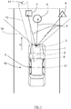
- FIG. 1 schematically shows a top view of a vehicle 7 that travels in a direction D on a road 16.
- the vehicle 7 comprises a vehicle detection system 1 that in turn comprises a control unit 2.
- the vehicle detection system 1 further comprises an environment detection system 3 that is adapted to detect objects 4, 5, 6 outside the vehicle 7.
- the environment detection system 3 comprises a first camera detector device 23.
- the environment detection system 3 also comprises at least one of a radar detector device 24 and a Lidar detector device 25.
- the devices comprised in the environment detection system 3 are well-known and provide data regarding detected objects 4, 5, 6, and in the case of two or more detector devices, the output of these detector devices can be combined. or fused such that a more detailed representation of the environment outside the vehicle 7 can be acquired for a certain sensor field of view 19.
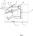
- the vehicle detection system 1 further comprises a driver attentiveness detection system 8 that is adapted to detect eye gaze direction of a driver's eye 9a.
- the driver attentiveness detection system 8 comprises a second camera detector device 20 and an image control unit 21.
- Such a driver attentiveness detection system 8 is for example described more in detail in SE 1530037 .
- the control unit 2 is adapted to acquire data regarding detected objects 4, 5, 6 from the environment detection system 3, and to acquire eye gaze direction data from the driver attentiveness detection system 8, where the eye gaze direction data comprises an eye gaze direction vector v that according to some aspects is a normalized vector. According to some aspects, the eye gaze direction data also comprises origin data for the eye gaze direction vector v , for example position of a driver's eyes 9a.
- control unit 2 is adapted to estimate to which extent a detected object 4 is occupying a driver's field of view 10 by means of a combination of the acquired data.
- control unit 2 is adapted to define a driver's field of view 10 by means of the acquired eye gaze direction data, and to represent the field of view 10 with at least one cone 10 having a corresponding base 11 having a center 15. This is also illustrated in Figure 7 , where the eye gaze direction vector v is shown, directed from the driver's eye 9a towards an imaginary gaze target 22, and where the cone 10 is formed uniformly around the gaze direction vector v such that imaginary target 22 coincides with the center 15.
- the base 11 has a base area S that comprises a pattern of sample points 13 indicated with dots, where the sample points 13 represent the effective field of view.
- each sample point 12 is related to a sample point vector 14 that runs in relation to the eye gaze direction vector v .
- each sample point vector 14 extends from the driver's eye 9a through a corresponding sample point 12. That means that as the driver's eye gaze direction is detected to change, the eye gaze direction vector v is updated and all sample points 13, 12 with corresponding sample point vectors 14 are updated accordingly.
- control unit 2 is adapted to estimate to which extent a detected object 4 is occupying a driver's field of view 10 by determining how many sample points 13 that coincide with the detected object 4.
- the vehicle detection system 1 is adapted to sample for objects inside the corresponding cone 10 by means of ray-casting which means that a ray runs along each sample point vector 14 and returns the first detected object in the path, if any. If, and how much, a detected object 4 occupies the driver's field of view 10 can be approximated by the fraction of samples that detected the object. Using the time and space a detected object 4 has occupied of the driver's field of view 10, the vehicle detection system 1 is adapted to estimate if the driver 9 has seen the detected object 4 or not. Depending on the outcome of this estimation, it is determined if the driver 9 can take a suitable action without any automated assistance or not.
- one or more systems 31 for safety and/or assisted driving as shown in Figure 1 is activated accordingly.
- the level of activation of said system 31 for safety and/or assisted driving can be set in accordance with the outcome of this estimation, for example certain threshold settings.
- the vehicle detection system 1 is adapted to estimate if a detected object has occupied the driver's field of view, both to which extent and for how long time. From this, a certain likelihood that the driver 9 actually has seen the detected object 4 can be determined and used for determining if the driver 9 can take a suitable action without any automated assistance or not.
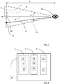
- first field of view 10 A with a first base 26 and first base area S A at a first distance d A of the detection range
- second field of view 10 B with a second base 27 and second base area S B at a second distance d A of the detection range.
- the first field of view 10 A is intended for relatively close objects 17
- the second field of view 10 B is intended for relatively remote objects 18.
- Each field of view 10 A , 10 B is represented by a corresponding cone 10 A , 10 B formed uniformly around the gaze direction vector v .
- the first base area S A comprises a first pattern of sample points 13 A indicated with crosses and the second base area S B comprises a second pattern of sample points 13 B indicated with dots, where the second pattern of sample points 13 B is denser than the first pattern of sample points 13 A in order to maintain a certain resolution due to the fact that the second base 27 and the second base area S B are more remote than the first base 26 and first base area S A .
- the first base 26 and first base area S A are positioned at the first distance d A of the detection range of about 10 meters from the driver 9, and the second base 27 and the second base area S B are positioned at the second distance d B of the detection range of about 100 meters from the driver's eye 9a.
- a field of view 10; 10 A , 10 B is represented by a cone having a circular base area S; S A , S B with a center 15.
- the term 5 + 1 2 ⁇ W , where W is an integer including zero, is according to some aspects known as the Golden Ratio, the Golden Section, the Golden Mean or the Tooth.
- the inner radius r i,SA for the first, outer, base area S A equals the outer radius r o,SB for the second, inner, base area S B .
- a number N SB of sample points 13 B within the second base area S B exceeds a number N SA of sample points 13 A within the first base area S A .
- the first base area S A comprises the second base area S B , such that the sample points 13 A within the first base area S A also are within the second base area S B . This can for example be the case if the resulting number of sample points 13 A for the first base area S A that are positioned within the second base area S B is relatively small.
- the cone 10 that defines a driver's field of view can be defined by means of the detection range ds and the angle of view ⁇ S . According to some aspects, the angle of view ⁇ S is about 4°.
- Equation (8) above is for example applicable for the scenario according to Figure 3 , Figure 5 and Figure 6 where X can be A or B.
- X can be A or B.
- first base area S A there is a first inner angle of view ⁇ i,SA and a first outer angle of view ⁇ o,SA .
- second base area S B there is a second outer angle of view ⁇ o,SB that equals the first inner angle of view ⁇ i,SA .
- a cumulative object coverage C M can be calculated, comprising a plurality of corresponding coverages C k , 1 ⁇ k ⁇ M.
- the present disclosure also relates to a method for a vehicle detection system 1, where the method comprises detecting S1 objects 4, 5, 6 outside a vehicle 7, detecting S2 eye gaze direction for a driver 9, acquiring S3 data regarding detected objects, and acquiring S4 eye gaze direction data.
- the eye gaze direction data comprises an eye gaze direction vector v .
- the method further comprises estimating S5 to which extent a detected object 4 is occupying a driver's field of view 10 using a combination of the acquired data.
- the method comprises defining S41 the driver's field of view 10 by means of the acquired eye gaze direction data, and representing S42 the field of view 10 with at least one cone 10 having a corresponding base 11.
- the base 11 comprises a pattern of sample points 13; 13 A , 13 B , where the sample points 13; 13 A , 13 B represent the effective field of view.
- the method comprises estimating to which extent a detected object 4 is occupying a driver's field of view 10 by determining S51 how many sample points 13 that coincide with the detected object 4.
- each base area S A , S B comprises a corresponding sub-pattern of sample points 13 A , 13 B , where at least two sub-patterns of sample points 13 A , 13 B have mutually different pattern density.
- each sample point 12 is related to a sample point vector 14 that runs in relation to the eye gaze direction vector v .
- FIG 8 schematically illustrates, in terms of a number of functional units, the components of the vehicle detection system 1 that comprises the control unit 2 according to an embodiment.
- Processing circuitry 28 is provided using any combination of one or more of a suitable central processing unit (CPU), multiprocessor, microcontroller, digital signal processor (DSP), dedicated hardware accelerator, etc., capable of executing software instructions stored in a computer program product, e.g. in the form of a storage medium 29.
- the processing circuitry 28 may further be provided as at least one application specific integrated circuit (ASIC), or field programmable gate array (FPGA).
- ASIC application specific integrated circuit
- FPGA field programmable gate array
- the processing circuitry 28 is configured to cause the control unit 2 to perform a set of operations, or steps. These operations, or steps, were discussed above in connection to Figure 11 .
- the storage medium 29 may store the set of operations
- the processing circuitry 28 may be configured to retrieve the set of operations from the storage medium 29 to cause the environment detection system 3, the driver attentiveness detection system 8 and/or one or more systems 31 for safety and assisted driving to perform the set of operations.
- the set of operations may be provided as a set of executable instructions.
- the processing circuitry 28 is thereby arranged to execute methods as herein disclosed.
- the storage medium 29 may also comprise persistent storage, which, for example, can be any single one or combination of magnetic memory, optical memory, solid state memory or even remotely mounted memory.
- the control unit 2 may further comprise a communications interface 30 for communications with the environment detection system 3, the driver attentiveness detection system 8 and/or one or more systems 31 for safety and assisted driving.
- Figure 10 shows a computer program product 32 comprising computer executable instructions 33 to execute any of the methods disclosed herein.
- a base area S, S A , S B can have any suitable shape, such as oval or polygonal, where the cone has a corresponding shape.
- the control unit 2 might be comprised by one or several units, and may also at least partly be comprised in another unit such as a vehicle restraint control unit.
- the image control unit 21 may be comprised in the control unit 2.
- the storage medium 29 comprises a model of the vehicle 7. This enables the control unit 2 to determine if the eye gaze direction vector v is directed towards an obscuring object comprised in the vehicle 7, such as for example an A-pillar.
- one or more external sensors comprised in the environment detection system 3 capture an image of the surrounding environment.
- the image can be formed by pixels, as in the case of camera detector device 23, where the pixels are formed by pixel coordinates that have to be converted to a coordinate system relative to the vehicle, a vehicle coordinate system.
- the image can also be formed by a point cloud in the case of a Lidar detector device 25 and by reflected energy returns in the case of a radar detector device 24.
- the control unit 2 is adapted to perform object detection for the image and to place the detected objects in the vehicle coordinate system. According to some aspects, the control unit 2 is adapted to perform object classification to determine what the objects are.
- the image control unit 21 is adapted to determine the eye gaze direction vector v , and the eye gaze direction vector v is mapped to the vehicle coordinate system.
- control unit 2 is adapted to place the detected objects into a virtual 3D world along with the drivers gaze, following the eye gaze direction vector v .
- control unit 2 is adapted to center the pattern of sample points 12 around the eye gaze direction vector v and to form rays from the gaze origin through each sample point, along the corresponding sample point vectors 14, and returns the first, if any, detected object in the path of the ray, performing ray-casting.
- control unit 2 is adapted to calculate the overlap of each known detected object of the field of view centered around the eye gaze direction vector v based on the number of positive sample points for each detected object.
- the acquired information is forwarded and/or used by functions that can use information regarding when and to which extent a detected object has been observed by the driver.
- the present disclosure relates to a vehicle detection system 1 comprising a control unit 2, an environment detection system 3 that is adapted to detect objects 4, 5, 6; 17, 18 outside a vehicle 7, and a driver attentiveness detection system 8 that is adapted to detect eye gaze direction of a driver 9.
- the control unit 2 is adapted to acquire data regarding detected objects 4, 5, 6; 17, 18 from the environment detection system 3, and to acquire eye gaze direction data from the driver attentiveness detection system 8, the eye gaze direction data comprising an eye gaze direction vector v.
- the control unit 2 is adapted to estimate to which extent a detected object 4 is occupying a driver's field of view 10 by means of a combination of the acquired data.
- control unit 2 is adapted to define the driver's field of view 10 by means of the acquired eye gaze direction data, and to represent the field of view 10 with at least one cone 10 having a corresponding base 11.
- the base 11 comprises a pattern of sample points 13; 13 A , 13 B , where the sample points 13; 13 A , 13 B represent the effective field of view.
- control unit 2 is adapted to estimate to which extent a detected object 4 is occupying a driver's field of view 10 by determining how many sample points 13 that coincide with the detected object 4.
- each base area S A , S B comprises a corresponding sub-pattern of sample points 13 A , 13 B , where at least two sub-patterns of sample points 13 A , 13 B have mutually different pattern density.
- each sample point 12 is related to a sample point vector 14 that runs in relation to the eye gaze direction vector v.
- the present disclosure also relates to a vehicle 7 comprising the vehicle detection system 1 according to the above
Landscapes
- Engineering & Computer Science (AREA)
- Physics & Mathematics (AREA)
- General Physics & Mathematics (AREA)
- Multimedia (AREA)
- Theoretical Computer Science (AREA)
- Traffic Control Systems (AREA)
Abstract
Description
- The present disclosure relates to a vehicle detection system comprising a control unit, an environment detection system that is adapted to detect objects outside a vehicle, and a driver attentiveness detection system that is adapted to detect eye gaze direction of a driver.
- A vehicle environment detection system, for example comprising camera systems, radio detection and ranging (radar) systems and light detection and ranging (Lidar) systems, can be mounted on a vehicle in order to detect objects in a vicinity of the vehicle. The obtained detections can be used to implement functions such as speed control and collision prevention, ego motion estimation and scene understanding. For this purpose, it is desired to represent tracked objects in an efficient an accurate manner, and to track the represented objects.
- It is, however, desired to avoid unnecessary automated actions, for example when a detected object has been observed by the driver and the driver can take a suitable action without any automated assistance. It is also desired to enhance the triggering of automated actions regarding a detected object that has not been observed by the driver.
- There is thus a need for a vehicle detection system and a corresponding method for estimating when and to which extent a detected object has been observed by the driver.
- Said object is achieved by means of a vehicle detection system comprising a control unit, an environment detection system that is adapted to detect objects outside a vehicle, and a driver attentiveness detection system that is adapted to detect eye gaze direction of a driver. The control unit is adapted to acquire data regarding detected objects from the environment detection system, and to acquire eye gaze direction data from the driver attentiveness detection system. The eye gaze direction data comprises an eye gaze direction vector. The control unit is adapted to estimate to which extent a detected object is occupying a driver's field of view by means of a combination of the acquired data.
- In this way, unnecessary automated actions are avoided, and at the same time triggering of automated actions regarding a detected object that has not been observed by the driver can be enhanced.
- According to some aspects, the control unit is adapted to define the driver's field of view by means of the acquired eye gaze direction data, and to represent the field of view with at least one cone having a corresponding base.
- In this way, an efficient mathematical representation of the driver's field of view is provided.
- According to some aspects, the base comprises a pattern of sample points, where the sample points represent the effective field of view.
- In this way, an efficient mathematical representation of the effective driver's field of view is provided.
- According to some aspects, the control unit is adapted to estimate to which extent a detected object is occupying a driver's field of view by determining how many sample points that coincide with the detected object.
- In this way, it can be estimated to which extent a detected object is occupying a driver's field of view in an efficient and reliable manner.
- According to some aspects, there are at least two field of views with a corresponding base and base area. Each base area comprises a corresponding sub-pattern of sample points, where at least two sub-patterns of sample points have mutually different pattern density.
- In this way the field of view can be divided in different part with different resolution which for example is beneficial when there are detected objects at different distances from the vehicle detection system comprising a control unit, an environment detection system.
- According to some aspects, each sample point is related to a sample point vector that runs in relation to the eye gaze direction vector.
- In this way, starting data that enable an efficient forming of the at least one cone are provided.
- According to some aspects, each field of view is represented by a cone having a circular base area with a center. A pattern or sub-pattern of sample points within each base area is formed according to


- Here, n is the number of the present sample point, where n runs from 1 to Ns that is the number of sample points within the base area S, rn,S is the radius from the center for sample point n, within the base area S, ri,S is the inner radius from the center for the base area S, ro,S is the outer radius from the center for the base area S, Ns is the number of sample points within the base area S, xn,S is an x-coordinate within the base area S for sample point n, yn,S is a y-coordinate within the base area S for sample point n, and θn,S is an angle between the radius to sample point n and the radius to the previous sample point n-1. Furthermore,

- In this way, an efficient and uniformly distributed pattern that provides a reliable representation of the effective driver's field of view is provided.
- There are also disclosed herein methods and vehicles associated with the above-mentioned advantages.
- The present disclosure will now be described more in detail with reference to the appended drawings, where:
- Figure 1
- shows a schematic top view of a vehicle;
- Figure 2
- shows a schematic cut-open side view of a vehicle;
- Figure 3
- shows a first schematic illustration of a base for a field of view cone;
- Figure 4
- shows a second schematic illustration of a base for a field of view cone;
- Figure 5
- shows a third schematic illustration of a base for a field of view cone;
- Figure 6
- shows a schematic illustration of a field of view cones for different detection ranges;
- Figure 7
- shows a schematic illustration of a field of view cone;
- Figure 8
- shows a schematic illustration of a vehicle detection system according to the present disclosure;
- Figure 9
- shows a fourth schematic illustration of a base for a field of view cone, the base having a general number of base areas;
- Figure 10
- shows an example computer program product; and
- Figure 11
- shows a flowchart for a method according to the present disclosure.
-
Figure 1 schematically shows a top view of avehicle 7 that travels in a direction D on aroad 16. Thevehicle 7 comprises avehicle detection system 1 that in turn comprises acontrol unit 2. Thevehicle detection system 1 further comprises anenvironment detection system 3 that is adapted to detectobjects vehicle 7. According to some aspects, with reference also toFigure 8 , theenvironment detection system 3 comprises a firstcamera detector device 23. According to some further aspects, theenvironment detection system 3 also comprises at least one of aradar detector device 24 and aLidar detector device 25. - The devices comprised in the
environment detection system 3 are well-known and provide data regarding detectedobjects vehicle 7 can be acquired for a certain sensor field ofview 19. - With reference also to
Figure 2 that schematically shows a cut-open part of thevehicle 7, thevehicle detection system 1 further comprises a driverattentiveness detection system 8 that is adapted to detect eye gaze direction of a driver'seye 9a. For this purpose, according to some aspects, the driverattentiveness detection system 8 comprises a secondcamera detector device 20 and animage control unit 21. Such a driverattentiveness detection system 8 is for example described more in detail inSE 1530037 - The
control unit 2 is adapted to acquire data regarding detectedobjects environment detection system 3, and to acquire eye gaze direction data from the driverattentiveness detection system 8, where the eye gaze direction data comprises an eye gaze direction vector v that according to some aspects is a normalized vector. According to some aspects, the eye gaze direction data also comprises origin data for the eye gaze direction vector v, for example position of a driver'seyes 9a. - According to the present disclosure, the
control unit 2 is adapted to estimate to which extent a detectedobject 4 is occupying a driver's field ofview 10 by means of a combination of the acquired data. - According to some aspects, the
control unit 2 is adapted to define a driver's field ofview 10 by means of the acquired eye gaze direction data, and to represent the field ofview 10 with at least onecone 10 having acorresponding base 11 having acenter 15. This is also illustrated inFigure 7 , where the eye gaze direction vector v is shown, directed from the driver'seye 9a towards animaginary gaze target 22, and where thecone 10 is formed uniformly around the gaze direction vector v such thatimaginary target 22 coincides with thecenter 15. - According to some aspects, as shown in
Figure 4 , thebase 11 has a base area S that comprises a pattern ofsample points 13 indicated with dots, where the sample points 13 represent the effective field of view. With reference also toFigure 7 , according to some aspects, eachsample point 12 is related to asample point vector 14 that runs in relation to the eye gaze direction vector v. According to some aspects, eachsample point vector 14 extends from the driver'seye 9a through acorresponding sample point 12. That means that as the driver's eye gaze direction is detected to change, the eye gaze direction vector v is updated and allsample points sample point vectors 14 are updated accordingly. - In this manner, by determining how many sample points that occupy a detected
object 4, it can be estimated to which extent a detectedobject 4 is occupying a driver's field ofview 10. In other words, thecontrol unit 2 is adapted to estimate to which extent a detectedobject 4 is occupying a driver's field ofview 10 by determining howmany sample points 13 that coincide with the detectedobject 4. - To determine if a detected
object 4 is in the field ofview 10, thevehicle detection system 1 is adapted to sample for objects inside the correspondingcone 10 by means of ray-casting which means that a ray runs along eachsample point vector 14 and returns the first detected object in the path, if any. If, and how much, a detectedobject 4 occupies the driver's field ofview 10 can be approximated by the fraction of samples that detected the object. Using the time and space a detectedobject 4 has occupied of the driver's field ofview 10, thevehicle detection system 1 is adapted to estimate if thedriver 9 has seen the detectedobject 4 or not. Depending on the outcome of this estimation, it is determined if thedriver 9 can take a suitable action without any automated assistance or not. If not, one ormore systems 31 for safety and/or assisted driving as shown inFigure 1 is activated accordingly. According to some aspects, the level of activation of saidsystem 31 for safety and/or assisted driving can be set in accordance with the outcome of this estimation, for example certain threshold settings. - It should be noted that due to sensor inaccuracies and reasons of human perception it cannot be absolutely known if the
driver 9 actually has seen the detectedobject 4, but thevehicle detection system 1 is adapted to estimate if a detected object has occupied the driver's field of view, both to which extent and for how long time. From this, a certain likelihood that thedriver 9 actually has seen the detectedobject 4 can be determined and used for determining if thedriver 9 can take a suitable action without any automated assistance or not. - With reference to
Figure 5 and Figure 6 , there is a first field ofview 10A with afirst base 26 and first base area SA at a first distance dA of the detection range, and a second field ofview 10B with asecond base 27 and second base area SB at a second distance dA of the detection range. The first field ofview 10A is intended for relativelyclose objects 17, and the second field ofview 10B is intended for relativelyremote objects 18. Each field ofview cone - The first base area SA comprises a first pattern of
sample points 13A indicated with crosses and the second base area SB comprises a second pattern ofsample points 13B indicated with dots, where the second pattern ofsample points 13B is denser than the first pattern ofsample points 13A in order to maintain a certain resolution due to the fact that thesecond base 27 and the second base area SB are more remote than thefirst base 26 and first base area SA. - According to some aspects, as an example, the
first base 26 and first base area SA are positioned at the first distance dA of the detection range of about 10 meters from thedriver 9, and thesecond base 27 and the second base area SB are positioned at the second distance dB of the detection range of about 100 meters from the driver'seye 9a. - As evident from
Figure 4 andFigure 5 , this means that the quality of the estimation is dependent on how the pattern ofsample points 13; 13A, 13B is formed. Therefore, in the following, it will be described how the pattern ofsample points 13; 13A, 13B can be formed. - With reference to
Figure 3, Figure 4 ,Figure 5 andFigure 7 , a field ofview 10; 10A, 10B is represented by a cone having a circular base area S; SA, SB with acenter 15. A general pattern or sub-pattern ofsample points 13 within a general base area S is formed according to:


- Here, n is the number of a present sample point, where n runs from 1 to Ns, where Ns is the number of sample points within the base area S, rn,S is the radius from the
center 15 for sample point n, within the base area S, ri,S is the inner radius from thecenter 15 for the base area S, ro,S is the outer radius from thecenter 15 for the base area S, NS is the number of sample points within the base area S, xn,S is an x-coordinate within the base area S for sample point n, yn,S is a y-coordinate within the base area S for sample point n, θn,S is an angle between the radius to sample point n and the radius to the previous sample point n-1, and where
- The
term 
- In this manner, a uniformly distributed pattern of
sample points 13; 13A, 13B is acquired. For the example inFigure 4 where there is only one base area S, the inner radius ri,S equals zero. - For the example in
Figure 3 andFigure 5 where there are two base areas SA, SB, the inner radius ri,SA for the first, outer, base area SA equals the outer radius ro,SB for the second, inner, base area SB. Here, a number NSB ofsample points 13B within the second base area SB exceeds a number NSA ofsample points 13A within the first base area SA. - According to some aspects, the first base area SA comprises the second base area SB, such that the sample points 13A within the first base area SA also are within the second base area SB. This can for example be the case if the resulting number of
sample points 13A for the first base area SA that are positioned within the second base area SB is relatively small. - With reference to
Figure 4 andFigure 7 , the outer radius ro,S of a base area S is
cone 10 that defines a driver's field of view can be defined by means of the detection range ds and the angle of view ψS . According to some aspects, the angle of view ψS is about 4°. Thesample point vector 14 can be expressed as:
sample points 13 required can be calculated according to:
- For example, having the distance of the detection range ds = 100m, the angle of view ψS = 4°, and the desired area per point or resolution

sample points 13 is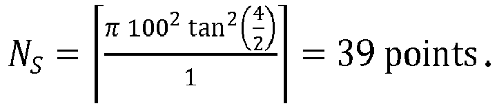
- The above number of points is only valid for a single base area S with inner angle of view ψSi = 0 degrees. A general formula for a base area SX with an inner angle of view ψi,SX > 0 and outer angle of view ψo,SX is:

- Equation (8) above is for example applicable for the scenario according to
Figure 3 ,Figure 5 and Figure 6 where X can be A or B. For the first base area SA there is a first inner angle of view ψi,SA and a first outer angle of view ψo,SA. For the second base area SB there is a second outer angle of view ψo,SB that equals the first inner angle of view ψi,SA . - With reference to
Figure 4 andFigure 5 , in order to estimate to which extent a detectedobject 4 is occupying a driver's field ofview 10 this can according to some aspects be calculated. - Having pS that is the number of samples points for a detected
object 4 in a certain base area S, and NS is the total number of samples points a certain base area S, an object fraction coverage FS of the base area S can be expressed as:
- For a single base area S, the above expression for F is identical to the total coverage C.
- For the two base areas SA, SB in
Figure 5 , a total object coverage C in multiple non-overlapping base areas can be expressed as:
- With reference to
Figure 9 , there is an arbitrary number M of base areas S1 ... SM, 1<k<M. It is to be noted that the base areas and associated parameters as described previously with reference toFigure 3 ,Figure 5 and Figure 6 were distinguished by subscripts in the form of letters such as A and B, and here, with reference toFigure 9 , the base areas and associated parameters are distinguished by subscripts in the form of numbers. Here, a total object coverage C can be expressed as:
- When neighboring segments share radii, a cumulative object coverage CM can be calculated, comprising a plurality of corresponding coverages Ck, 1<k<M.


- With reference to
Figure 11 , the present disclosure also relates to a method for avehicle detection system 1, where the method comprises detecting S1 objects 4, 5, 6 outside avehicle 7, detecting S2 eye gaze direction for adriver 9, acquiring S3 data regarding detected objects, and acquiring S4 eye gaze direction data. The eye gaze direction data comprises an eye gaze direction vector v. - The method further comprises estimating S5 to which extent a detected
object 4 is occupying a driver's field ofview 10 using a combination of the acquired data. - According to some aspects, the method comprises defining S41 the driver's field of
view 10 by means of the acquired eye gaze direction data, and representing S42 the field ofview 10 with at least onecone 10 having acorresponding base 11. - According to some aspects, the
base 11 comprises a pattern ofsample points 13; 13A, 13B, where the sample points 13; 13A, 13B represent the effective field of view. - According to some aspects, the method comprises estimating to which extent a detected
object 4 is occupying a driver's field ofview 10 by determining S51 howmany sample points 13 that coincide with the detectedobject 4. - According to some aspects, there are at least two field of
views corresponding base sample points sample points - According to some aspects, each
sample point 12 is related to asample point vector 14 that runs in relation to the eye gaze direction vector v. - According to some aspects, each field of view 10; 10A, 10B is represented by a cone having a circular base area S; SA, SB with a center 15, where a pattern or sub-pattern of sample points 13; 13A, 13B within each base area S; SA, SB is formed according to


-
Figure 8 schematically illustrates, in terms of a number of functional units, the components of thevehicle detection system 1 that comprises thecontrol unit 2 according to an embodiment.Processing circuitry 28 is provided using any combination of one or more of a suitable central processing unit (CPU), multiprocessor, microcontroller, digital signal processor (DSP), dedicated hardware accelerator, etc., capable of executing software instructions stored in a computer program product, e.g. in the form of astorage medium 29. Theprocessing circuitry 28 may further be provided as at least one application specific integrated circuit (ASIC), or field programmable gate array (FPGA). - Particularly, the
processing circuitry 28 is configured to cause thecontrol unit 2 to perform a set of operations, or steps. These operations, or steps, were discussed above in connection toFigure 11 . For example, thestorage medium 29 may store the set of operations, and theprocessing circuitry 28 may be configured to retrieve the set of operations from thestorage medium 29 to cause theenvironment detection system 3, the driverattentiveness detection system 8 and/or one ormore systems 31 for safety and assisted driving to perform the set of operations. The set of operations may be provided as a set of executable instructions. Thus, theprocessing circuitry 28 is thereby arranged to execute methods as herein disclosed. - The
storage medium 29 may also comprise persistent storage, which, for example, can be any single one or combination of magnetic memory, optical memory, solid state memory or even remotely mounted memory. - The
control unit 2 may further comprise acommunications interface 30 for communications with theenvironment detection system 3, the driverattentiveness detection system 8 and/or one ormore systems 31 for safety and assisted driving. -
Figure 10 shows acomputer program product 32 comprising computerexecutable instructions 33 to execute any of the methods disclosed herein. - The present disclosure is not limited to the above, but may vary freely within the scope of the appended claims. For example, a base area S, SA, SB can have any suitable shape, such as oval or polygonal, where the cone has a corresponding shape.
- The
control unit 2 might be comprised by one or several units, and may also at least partly be comprised in another unit such as a vehicle restraint control unit. Theimage control unit 21 may be comprised in thecontrol unit 2. - The signal processing and estimations are carried out by means of suitable processing algorithm, such algorithms are well-known and details of these will not be discussed further.
- According to some aspects, the
storage medium 29 comprises a model of thevehicle 7. This enables thecontrol unit 2 to determine if the eye gaze direction vector v is directed towards an obscuring object comprised in thevehicle 7, such as for example an A-pillar. - According to some aspects, in accordance with the present disclosure, one or more external sensors comprised in the
environment detection system 3 capture an image of the surrounding environment. The image can be formed by pixels, as in the case ofcamera detector device 23, where the pixels are formed by pixel coordinates that have to be converted to a coordinate system relative to the vehicle, a vehicle coordinate system. The image can also be formed by a point cloud in the case of aLidar detector device 25 and by reflected energy returns in the case of aradar detector device 24. - The
control unit 2 is adapted to perform object detection for the image and to place the detected objects in the vehicle coordinate system. According to some aspects, thecontrol unit 2 is adapted to perform object classification to determine what the objects are. - According to some aspects, the
image control unit 21 is adapted to determine the eye gaze direction vector v, and the eye gaze direction vector v is mapped to the vehicle coordinate system. - According to some aspects, the
control unit 2 is adapted to place the detected objects into a virtual 3D world along with the drivers gaze, following the eye gaze direction vector v. - According to some aspects, the
control unit 2 is adapted to center the pattern ofsample points 12 around the eye gaze direction vector v and to form rays from the gaze origin through each sample point, along the correspondingsample point vectors 14, and returns the first, if any, detected object in the path of the ray, performing ray-casting. According to some aspects, thecontrol unit 2 is adapted to calculate the overlap of each known detected object of the field of view centered around the eye gaze direction vector v based on the number of positive sample points for each detected object. The acquired information is forwarded and/or used by functions that can use information regarding when and to which extent a detected object has been observed by the driver. This is for example the case for automated assistance systems such as automated driving systems and automated safety systems that can determine if a detected object has been observed by the driver and the driver can take a suitable action without any automated assistance or if a detected object has not been observed by the driver, requiring enhanced triggering of automated actions. - Generally, the present disclosure relates to a
vehicle detection system 1 comprising acontrol unit 2, anenvironment detection system 3 that is adapted to detectobjects vehicle 7, and a driverattentiveness detection system 8 that is adapted to detect eye gaze direction of adriver 9. Thecontrol unit 2 is adapted to acquire data regarding detectedobjects environment detection system 3, and to acquire eye gaze direction data from the driverattentiveness detection system 8, the eye gaze direction data comprising an eye gaze direction vector v. Thecontrol unit 2 is adapted to estimate to which extent a detectedobject 4 is occupying a driver's field ofview 10 by means of a combination of the acquired data. - According to some aspects, the
control unit 2 is adapted to define the driver's field ofview 10 by means of the acquired eye gaze direction data, and to represent the field ofview 10 with at least onecone 10 having acorresponding base 11. - According to some aspects, the
base 11 comprises a pattern ofsample points 13; 13A, 13B, where the sample points 13; 13A, 13B represent the effective field of view. - According to some aspects, the
control unit 2 is adapted to estimate to which extent a detectedobject 4 is occupying a driver's field ofview 10 by determining howmany sample points 13 that coincide with the detectedobject 4. - According to some aspects, there are at least two field of
views corresponding base sample points sample points - According to some aspects, each
sample point 12 is related to asample point vector 14 that runs in relation to the eye gaze direction vector v. - According to some aspects, each field of view 10; 10A, 10B is represented by a cone having a circular base area S; SA, SB with a center 15, where a pattern or sub-pattern of sample points 13; 13A, 13B within each base area S; SA, SB is formed according to


- Generally, the present disclosure also relates to a
vehicle 7 comprising thevehicle detection system 1 according to the above
Claims (15)
- A vehicle detection system (1) comprising a control unit (2), an environment detection system (3) that is adapted to detect objects (4, 5, 6; 17, 18) outside a vehicle (7), and a driver attentiveness detection system (8) that is adapted to detect eye gaze direction of a driver (9), where the control unit (2) is adapted to acquire data regarding detected objects (4, 5, 6; 17, 18) from the environment detection system (3), and to acquire eye gaze direction data from the driver attentiveness detection system (8), the eye gaze direction data comprising an eye gaze direction vector (v), characterized in that the control unit (2) is adapted to estimate to which extent a detected object (4) is occupying a driver's field of view (10) by means of a combination of the acquired data.
- The vehicle detection system (1) according to claim 1, wherein the control unit (2) is adapted to define the driver's field of view (10) by means of the acquired eye gaze direction data, and to represent the field of view (10) with at least one cone (10) having a corresponding base (11).
- The vehicle detection system according to claim 2, wherein the base (11) comprises a pattern of sample points (13; 13A, 13B), where the sample points (13; 13A, 13B) represent the effective field of view.
- The vehicle detection system according to claim 3, wherein the control unit (2) is adapted to estimate to which extent a detected object (4) is occupying a driver's field of view (10) by determining how many sample points (13) that coincide with the detected object (4).
- The vehicle detection system according to any one of the claims 3 or 4, wherein there are at least two field of views (10A, 10B) with a corresponding base (26, 27) and base area (SA, SB), where each base area (SA, SB) comprises a corresponding sub-pattern of sample points (13A, 13B), where at least two sub-patterns of sample points (13A, 13B) have mutually different pattern density.
- The vehicle detection system according to any one of the claims 3-5, wherein each sample point (12) is related to a sample point vector (14) that runs in relation to the eye gaze direction vector (v).
- The vehicle detection system according to any one of the claims 3-6, wherein each field of view (10; 10A, 10B) is represented by a cone having a circular base area (S; SA, SB) with a center (15), where a pattern or sub-pattern of sample points (13; 13A, 13B) within each base area (S; SA, SB) is formed according to


- A vehicle (7) comprising the vehicle detection system 1) according to any one of the claims 1-7.
- A method for a vehicle detection system (1), where the method comprises:detecting (S1) objects (4, 5, 6) outside a vehicle (7) ;detecting (S2) eye gaze direction for a driver (9);acquiring (S3) data regarding detected objects; andacquiring (S4) eye gaze direction data, the eye gaze direction data comprising an eye gaze direction vector (v); characterized in that the method further comprises:estimating (S5) to which extent a detected object (4) is occupying a driver's field of view (10) using a combination of the acquired data.
- The method according to claim 9, wherein the method comprises:defining (S41) the driver's field of view (10) by means of the acquired eye gaze direction data, andrepresenting (S42) the field of view (10) with at least one cone (10) having a corresponding base (11).
- The method according to claim 10, wherein the base (11) comprises a pattern of sample points (13; 13A, 13B), where the sample points (13; 13A, 13B) represent the effective field of view.
- The method according to claim 11, wherein the method comprises estimating to which extent a detected object (4) is occupying a driver's field of view (10) by:
determining (S51) how many sample points (13) that coincide with the detected object (4). - The method according to any one of the claims 11 or 12, wherein there are at least two field of views (10A, 10B) with a corresponding base (26, 27) and base area (SA, SB), where each base area (SA, SB) comprises a corresponding sub-pattern of sample points (13A, 13B), where at least two sub-patterns of sample points (13A, 13B) have mutually different pattern density.
- The method according to any one of the claims 11-13, wherein each sample point (12) is related to a sample point vector (14) that runs in relation to the eye gaze direction vector (v).
- The method according to any one of the claims 11-14, wherein each field of view (10; 10A, 10B) is represented by a cone having a circular base area (S; SA, SB) with a center (15), where a pattern or sub-pattern of sample points (13; 13A, 13B) within each base area (S; SA, SB) is formed according to


Priority Applications (1)
| Application Number | Priority Date | Filing Date | Title |
|---|---|---|---|
| EP19212437.8A EP3828755B1 (en) | 2019-11-29 | 2019-11-29 | Improved estimation of driver attention |
Applications Claiming Priority (1)
| Application Number | Priority Date | Filing Date | Title |
|---|---|---|---|
| EP19212437.8A EP3828755B1 (en) | 2019-11-29 | 2019-11-29 | Improved estimation of driver attention |
Publications (2)
| Publication Number | Publication Date |
|---|---|
| EP3828755A1 true EP3828755A1 (en) | 2021-06-02 |
| EP3828755B1 EP3828755B1 (en) | 2023-07-19 |
Family
ID=68732860
Family Applications (1)
| Application Number | Title | Priority Date | Filing Date |
|---|---|---|---|
| EP19212437.8A Active EP3828755B1 (en) | 2019-11-29 | 2019-11-29 | Improved estimation of driver attention |
Country Status (1)
| Country | Link |
|---|---|
| EP (1) | EP3828755B1 (en) |
Cited By (1)
| Publication number | Priority date | Publication date | Assignee | Title |
|---|---|---|---|---|
| EP4040405A2 (en) * | 2021-06-25 | 2022-08-10 | Apollo Intelligent Connectivity (Beijing) Technology Co., Ltd. | Method and apparatus for tracking sight line, device, storage medium, and computer program product |
Families Citing this family (1)
| Publication number | Priority date | Publication date | Assignee | Title |
|---|---|---|---|---|
| EP4513462A1 (en) | 2023-08-23 | 2025-02-26 | Magna Electronics Sweden AB | Method for vehicle collision avoidance |
Citations (1)
| Publication number | Priority date | Publication date | Assignee | Title |
|---|---|---|---|---|
| SE1530037A1 (en) | 2014-04-03 | 2015-10-04 | Autoliv Dev | Driver attentiveness detection method and device |
-
2019
- 2019-11-29 EP EP19212437.8A patent/EP3828755B1/en active Active
Patent Citations (1)
| Publication number | Priority date | Publication date | Assignee | Title |
|---|---|---|---|---|
| SE1530037A1 (en) | 2014-04-03 | 2015-10-04 | Autoliv Dev | Driver attentiveness detection method and device |
Non-Patent Citations (4)
| Title |
|---|
| L. FLETCHER ET AL: "Driver Inattention Detection based on Eye Gaze--Road Event Correlation", INTERNATIONAL JOURNAL OF ROBOTICS RESEARCH., vol. 28, no. 6, 20 May 2009 (2009-05-20), US, pages 774 - 801, XP055281585, ISSN: 0278-3649, DOI: 10.1177/0278364908099459 * |
| LANGNER TOBIAS ET AL: "Traffic awareness driver assistance based on stereovision, eye-tracking, and head-up display", 2016 IEEE INTERNATIONAL CONFERENCE ON ROBOTICS AND AUTOMATION (ICRA), IEEE, 16 May 2016 (2016-05-16), pages 3167 - 3173, XP032908555, DOI: 10.1109/ICRA.2016.7487485 * |
| SCHWEHR JULIAN ET AL: "Driver's gaze prediction in dynamic automotive scenes", 2017 IEEE 20TH INTERNATIONAL CONFERENCE ON INTELLIGENT TRANSPORTATION SYSTEMS (ITSC), IEEE, 16 October 2017 (2017-10-16), pages 1 - 8, XP033330259, DOI: 10.1109/ITSC.2017.8317586 * |
| TAWARI ASHISH ET AL: "Attention estimation by simultaneous analysis of viewer and view", 17TH INTERNATIONAL IEEE CONFERENCE ON INTELLIGENT TRANSPORTATION SYSTEMS (ITSC), IEEE, 8 October 2014 (2014-10-08), pages 1381 - 1387, XP032685892, DOI: 10.1109/ITSC.2014.6957880 * |
Cited By (1)
| Publication number | Priority date | Publication date | Assignee | Title |
|---|---|---|---|---|
| EP4040405A2 (en) * | 2021-06-25 | 2022-08-10 | Apollo Intelligent Connectivity (Beijing) Technology Co., Ltd. | Method and apparatus for tracking sight line, device, storage medium, and computer program product |
Also Published As
| Publication number | Publication date |
|---|---|
| EP3828755B1 (en) | 2023-07-19 |
Similar Documents
| Publication | Publication Date | Title |
|---|---|---|
| CN111352110B (en) | Method and device for processing radar data | |
| US9073484B2 (en) | Surrounding area monitoring apparatus for vehicle | |
| EP2993654B1 (en) | Method and system for forward collision warning | |
| JP5870908B2 (en) | Vehicle collision determination device | |
| US20190065878A1 (en) | Fusion of radar and vision sensor systems | |
| US10592755B2 (en) | Apparatus and method for controlling vehicle | |
| JP4521642B2 (en) | Vehicle periphery monitoring device, vehicle, vehicle periphery monitoring program | |
| CN107306338A (en) | Panoramic camera system for object detection and tracking | |
| US20170080929A1 (en) | Movement-assisting device | |
| US9530063B2 (en) | Lane-line recognition apparatus including a masking area setter to set a masking area ahead of a vehicle in an image captured by an image capture unit | |
| EP3530536A1 (en) | Autonomous emergency braking system and method for vehicle at crossroad | |
| EP3555854B1 (en) | A method of tracking objects in a scene | |
| CN109583416B (en) | Pseudo lane line identification method and system | |
| EP3467545A1 (en) | Object classification | |
| JP5927110B2 (en) | Vehicle external recognition device | |
| JP2018147399A (en) | Target detection device | |
| EP3828755B1 (en) | Improved estimation of driver attention | |
| US12153128B2 (en) | Apparatus and method for vehicle control in the presence of temporarily obscured moving obstacles | |
| JP2016181072A (en) | Object recognition device | |
| Gaikwad et al. | An improved lane departure method for advanced driver assistance system | |
| US20050004719A1 (en) | Device and method for determining the position of objects in the surroundings of a motor vehicle | |
| EP3495222A1 (en) | Image-capturing device | |
| Sharma et al. | A much advanced and efficient lane detection algorithm for intelligent highway safety | |
| Hyun et al. | Multi-level Fusion Scheme for Target Classification using Camera and Radar Sensors | |
| EP3825648B1 (en) | Object detection device |
Legal Events
| Date | Code | Title | Description |
|---|---|---|---|
| PUAI | Public reference made under article 153(3) epc to a published international application that has entered the european phase |
Free format text: ORIGINAL CODE: 0009012 |
|
| STAA | Information on the status of an ep patent application or granted ep patent |
Free format text: STATUS: THE APPLICATION HAS BEEN PUBLISHED |
|
| AK | Designated contracting states |
Kind code of ref document: A1 Designated state(s): AL AT BE BG CH CY CZ DE DK EE ES FI FR GB GR HR HU IE IS IT LI LT LU LV MC MK MT NL NO PL PT RO RS SE SI SK SM TR |
|
| STAA | Information on the status of an ep patent application or granted ep patent |
Free format text: STATUS: REQUEST FOR EXAMINATION WAS MADE |
|
| 17P | Request for examination filed |
Effective date: 20211130 |
|
| RBV | Designated contracting states (corrected) |
Designated state(s): AL AT BE BG CH CY CZ DE DK EE ES FI FR GB GR HR HU IE IS IT LI LT LU LV MC MK MT NL NO PL PT RO RS SE SI SK SM TR |
|
| REG | Reference to a national code |
Ipc: G06V0020580000 Ref country code: DE Ref legal event code: R079 Ref document number: 602019032940 Country of ref document: DE Free format text: PREVIOUS MAIN CLASS: G06K0009000000 Ipc: G06V0020580000 |
|
| GRAP | Despatch of communication of intention to grant a patent |
Free format text: ORIGINAL CODE: EPIDOSNIGR1 |
|
| STAA | Information on the status of an ep patent application or granted ep patent |
Free format text: STATUS: GRANT OF PATENT IS INTENDED |
|
| RIC1 | Information provided on ipc code assigned before grant |
Ipc: G06V 40/18 20220101ALI20230117BHEP Ipc: G06V 20/58 20220101AFI20230117BHEP |
|
| INTG | Intention to grant announced |
Effective date: 20230213 |
|
| GRAS | Grant fee paid |
Free format text: ORIGINAL CODE: EPIDOSNIGR3 |
|
| GRAA | (expected) grant |
Free format text: ORIGINAL CODE: 0009210 |
|
| STAA | Information on the status of an ep patent application or granted ep patent |
Free format text: STATUS: THE PATENT HAS BEEN GRANTED |
|
| AK | Designated contracting states |
Kind code of ref document: B1 Designated state(s): AL AT BE BG CH CY CZ DE DK EE ES FI FR GB GR HR HU IE IS IT LI LT LU LV MC MK MT NL NO PL PT RO RS SE SI SK SM TR |
|
| REG | Reference to a national code |
Ref country code: GB Ref legal event code: FG4D |
|
| REG | Reference to a national code |
Ref country code: CH Ref legal event code: EP |
|
| REG | Reference to a national code |
Ref country code: DE Ref legal event code: R096 Ref document number: 602019032940 Country of ref document: DE |
|
| REG | Reference to a national code |
Ref country code: IE Ref legal event code: FG4D |
|
| REG | Reference to a national code |
Ref country code: SE Ref legal event code: TRGR |
|
| REG | Reference to a national code |
Ref country code: LT Ref legal event code: MG9D |
|
| REG | Reference to a national code |
Ref country code: NL Ref legal event code: MP Effective date: 20230719 |
|
| REG | Reference to a national code |
Ref country code: AT Ref legal event code: MK05 Ref document number: 1590262 Country of ref document: AT Kind code of ref document: T Effective date: 20230719 |
|
| PG25 | Lapsed in a contracting state [announced via postgrant information from national office to epo] |
Ref country code: NL Free format text: LAPSE BECAUSE OF FAILURE TO SUBMIT A TRANSLATION OF THE DESCRIPTION OR TO PAY THE FEE WITHIN THE PRESCRIBED TIME-LIMIT Effective date: 20230719 |
|
| PG25 | Lapsed in a contracting state [announced via postgrant information from national office to epo] |
Ref country code: GR Free format text: LAPSE BECAUSE OF FAILURE TO SUBMIT A TRANSLATION OF THE DESCRIPTION OR TO PAY THE FEE WITHIN THE PRESCRIBED TIME-LIMIT Effective date: 20231020 |
|
| PG25 | Lapsed in a contracting state [announced via postgrant information from national office to epo] |
Ref country code: IS Free format text: LAPSE BECAUSE OF FAILURE TO SUBMIT A TRANSLATION OF THE DESCRIPTION OR TO PAY THE FEE WITHIN THE PRESCRIBED TIME-LIMIT Effective date: 20231119 |
|
| PG25 | Lapsed in a contracting state [announced via postgrant information from national office to epo] |
Ref country code: RS Free format text: LAPSE BECAUSE OF FAILURE TO SUBMIT A TRANSLATION OF THE DESCRIPTION OR TO PAY THE FEE WITHIN THE PRESCRIBED TIME-LIMIT Effective date: 20230719 Ref country code: PT Free format text: LAPSE BECAUSE OF FAILURE TO SUBMIT A TRANSLATION OF THE DESCRIPTION OR TO PAY THE FEE WITHIN THE PRESCRIBED TIME-LIMIT Effective date: 20231120 Ref country code: NO Free format text: LAPSE BECAUSE OF FAILURE TO SUBMIT A TRANSLATION OF THE DESCRIPTION OR TO PAY THE FEE WITHIN THE PRESCRIBED TIME-LIMIT Effective date: 20231019 Ref country code: LV Free format text: LAPSE BECAUSE OF FAILURE TO SUBMIT A TRANSLATION OF THE DESCRIPTION OR TO PAY THE FEE WITHIN THE PRESCRIBED TIME-LIMIT Effective date: 20230719 Ref country code: LT Free format text: LAPSE BECAUSE OF FAILURE TO SUBMIT A TRANSLATION OF THE DESCRIPTION OR TO PAY THE FEE WITHIN THE PRESCRIBED TIME-LIMIT Effective date: 20230719 Ref country code: IS Free format text: LAPSE BECAUSE OF FAILURE TO SUBMIT A TRANSLATION OF THE DESCRIPTION OR TO PAY THE FEE WITHIN THE PRESCRIBED TIME-LIMIT Effective date: 20231119 Ref country code: HR Free format text: LAPSE BECAUSE OF FAILURE TO SUBMIT A TRANSLATION OF THE DESCRIPTION OR TO PAY THE FEE WITHIN THE PRESCRIBED TIME-LIMIT Effective date: 20230719 Ref country code: GR Free format text: LAPSE BECAUSE OF FAILURE TO SUBMIT A TRANSLATION OF THE DESCRIPTION OR TO PAY THE FEE WITHIN THE PRESCRIBED TIME-LIMIT Effective date: 20231020 Ref country code: FI Free format text: LAPSE BECAUSE OF FAILURE TO SUBMIT A TRANSLATION OF THE DESCRIPTION OR TO PAY THE FEE WITHIN THE PRESCRIBED TIME-LIMIT Effective date: 20230719 Ref country code: AT Free format text: LAPSE BECAUSE OF FAILURE TO SUBMIT A TRANSLATION OF THE DESCRIPTION OR TO PAY THE FEE WITHIN THE PRESCRIBED TIME-LIMIT Effective date: 20230719 |
|
| PG25 | Lapsed in a contracting state [announced via postgrant information from national office to epo] |
Ref country code: PL Free format text: LAPSE BECAUSE OF FAILURE TO SUBMIT A TRANSLATION OF THE DESCRIPTION OR TO PAY THE FEE WITHIN THE PRESCRIBED TIME-LIMIT Effective date: 20230719 |
|
| REG | Reference to a national code |
Ref country code: DE Ref legal event code: R081 Ref document number: 602019032940 Country of ref document: DE Owner name: MAGNA ELECTRONICS SWEDEN AB, SE Free format text: FORMER OWNER: VEONEER SWEDEN AB, VARGARDA, SE |
|
| REG | Reference to a national code |
Ref country code: DE Ref legal event code: R097 Ref document number: 602019032940 Country of ref document: DE |
|
| PG25 | Lapsed in a contracting state [announced via postgrant information from national office to epo] |
Ref country code: ES Free format text: LAPSE BECAUSE OF FAILURE TO SUBMIT A TRANSLATION OF THE DESCRIPTION OR TO PAY THE FEE WITHIN THE PRESCRIBED TIME-LIMIT Effective date: 20230719 |
|
| PG25 | Lapsed in a contracting state [announced via postgrant information from national office to epo] |
Ref country code: SM Free format text: LAPSE BECAUSE OF FAILURE TO SUBMIT A TRANSLATION OF THE DESCRIPTION OR TO PAY THE FEE WITHIN THE PRESCRIBED TIME-LIMIT Effective date: 20230719 Ref country code: RO Free format text: LAPSE BECAUSE OF FAILURE TO SUBMIT A TRANSLATION OF THE DESCRIPTION OR TO PAY THE FEE WITHIN THE PRESCRIBED TIME-LIMIT Effective date: 20230719 Ref country code: ES Free format text: LAPSE BECAUSE OF FAILURE TO SUBMIT A TRANSLATION OF THE DESCRIPTION OR TO PAY THE FEE WITHIN THE PRESCRIBED TIME-LIMIT Effective date: 20230719 Ref country code: EE Free format text: LAPSE BECAUSE OF FAILURE TO SUBMIT A TRANSLATION OF THE DESCRIPTION OR TO PAY THE FEE WITHIN THE PRESCRIBED TIME-LIMIT Effective date: 20230719 Ref country code: DK Free format text: LAPSE BECAUSE OF FAILURE TO SUBMIT A TRANSLATION OF THE DESCRIPTION OR TO PAY THE FEE WITHIN THE PRESCRIBED TIME-LIMIT Effective date: 20230719 Ref country code: CZ Free format text: LAPSE BECAUSE OF FAILURE TO SUBMIT A TRANSLATION OF THE DESCRIPTION OR TO PAY THE FEE WITHIN THE PRESCRIBED TIME-LIMIT Effective date: 20230719 Ref country code: SK Free format text: LAPSE BECAUSE OF FAILURE TO SUBMIT A TRANSLATION OF THE DESCRIPTION OR TO PAY THE FEE WITHIN THE PRESCRIBED TIME-LIMIT Effective date: 20230719 |
|
| PLBE | No opposition filed within time limit |
Free format text: ORIGINAL CODE: 0009261 |
|
| STAA | Information on the status of an ep patent application or granted ep patent |
Free format text: STATUS: NO OPPOSITION FILED WITHIN TIME LIMIT |
|
| PG25 | Lapsed in a contracting state [announced via postgrant information from national office to epo] |
Ref country code: IT Free format text: LAPSE BECAUSE OF FAILURE TO SUBMIT A TRANSLATION OF THE DESCRIPTION OR TO PAY THE FEE WITHIN THE PRESCRIBED TIME-LIMIT Effective date: 20230719 |
|
| 26N | No opposition filed |
Effective date: 20240422 |
|
| REG | Reference to a national code |
Ref country code: CH Ref legal event code: PL |
|
| PG25 | Lapsed in a contracting state [announced via postgrant information from national office to epo] |
Ref country code: MC Free format text: LAPSE BECAUSE OF FAILURE TO SUBMIT A TRANSLATION OF THE DESCRIPTION OR TO PAY THE FEE WITHIN THE PRESCRIBED TIME-LIMIT Effective date: 20230719 |
|
| PG25 | Lapsed in a contracting state [announced via postgrant information from national office to epo] |
Ref country code: LU Free format text: LAPSE BECAUSE OF NON-PAYMENT OF DUE FEES Effective date: 20231129 |
|
| PG25 | Lapsed in a contracting state [announced via postgrant information from national office to epo] |
Ref country code: CH Free format text: LAPSE BECAUSE OF NON-PAYMENT OF DUE FEES Effective date: 20231130 |
|
| GBPC | Gb: european patent ceased through non-payment of renewal fee |
Effective date: 20231129 |
|
| PG25 | Lapsed in a contracting state [announced via postgrant information from national office to epo] |
Ref country code: MC Free format text: LAPSE BECAUSE OF FAILURE TO SUBMIT A TRANSLATION OF THE DESCRIPTION OR TO PAY THE FEE WITHIN THE PRESCRIBED TIME-LIMIT Effective date: 20230719 Ref country code: LU Free format text: LAPSE BECAUSE OF NON-PAYMENT OF DUE FEES Effective date: 20231129 Ref country code: CH Free format text: LAPSE BECAUSE OF NON-PAYMENT OF DUE FEES Effective date: 20231130 Ref country code: SI Free format text: LAPSE BECAUSE OF FAILURE TO SUBMIT A TRANSLATION OF THE DESCRIPTION OR TO PAY THE FEE WITHIN THE PRESCRIBED TIME-LIMIT Effective date: 20230719 |
|
| REG | Reference to a national code |
Ref country code: BE Ref legal event code: MM Effective date: 20231130 |
|
| REG | Reference to a national code |
Ref country code: IE Ref legal event code: MM4A |
|
| PG25 | Lapsed in a contracting state [announced via postgrant information from national office to epo] |
Ref country code: IE Free format text: LAPSE BECAUSE OF NON-PAYMENT OF DUE FEES Effective date: 20231129 |
|
| PG25 | Lapsed in a contracting state [announced via postgrant information from national office to epo] |
Ref country code: GB Free format text: LAPSE BECAUSE OF NON-PAYMENT OF DUE FEES Effective date: 20231129 |
|
| PG25 | Lapsed in a contracting state [announced via postgrant information from national office to epo] |
Ref country code: BE Free format text: LAPSE BECAUSE OF NON-PAYMENT OF DUE FEES Effective date: 20231130 |
|
| PG25 | Lapsed in a contracting state [announced via postgrant information from national office to epo] |
Ref country code: IE Free format text: LAPSE BECAUSE OF NON-PAYMENT OF DUE FEES Effective date: 20231129 Ref country code: GB Free format text: LAPSE BECAUSE OF NON-PAYMENT OF DUE FEES Effective date: 20231129 Ref country code: BE Free format text: LAPSE BECAUSE OF NON-PAYMENT OF DUE FEES Effective date: 20231130 |
|
| PG25 | Lapsed in a contracting state [announced via postgrant information from national office to epo] |
Ref country code: BG Free format text: LAPSE BECAUSE OF FAILURE TO SUBMIT A TRANSLATION OF THE DESCRIPTION OR TO PAY THE FEE WITHIN THE PRESCRIBED TIME-LIMIT Effective date: 20230719 |
|
| PG25 | Lapsed in a contracting state [announced via postgrant information from national office to epo] |
Ref country code: BG Free format text: LAPSE BECAUSE OF FAILURE TO SUBMIT A TRANSLATION OF THE DESCRIPTION OR TO PAY THE FEE WITHIN THE PRESCRIBED TIME-LIMIT Effective date: 20230719 |
|
| PG25 | Lapsed in a contracting state [announced via postgrant information from national office to epo] |
Ref country code: CY Free format text: LAPSE BECAUSE OF FAILURE TO SUBMIT A TRANSLATION OF THE DESCRIPTION OR TO PAY THE FEE WITHIN THE PRESCRIBED TIME-LIMIT; INVALID AB INITIO Effective date: 20191129 |
|
| PG25 | Lapsed in a contracting state [announced via postgrant information from national office to epo] |
Ref country code: HU Free format text: LAPSE BECAUSE OF FAILURE TO SUBMIT A TRANSLATION OF THE DESCRIPTION OR TO PAY THE FEE WITHIN THE PRESCRIBED TIME-LIMIT; INVALID AB INITIO Effective date: 20191129 |
|
| PG25 | Lapsed in a contracting state [announced via postgrant information from national office to epo] |
Ref country code: TR Free format text: LAPSE BECAUSE OF FAILURE TO SUBMIT A TRANSLATION OF THE DESCRIPTION OR TO PAY THE FEE WITHIN THE PRESCRIBED TIME-LIMIT Effective date: 20230719 |
|
| PGFP | Annual fee paid to national office [announced via postgrant information from national office to epo] |
Ref country code: DE Payment date: 20251118 Year of fee payment: 7 |
|
| PGFP | Annual fee paid to national office [announced via postgrant information from national office to epo] |
Ref country code: FR Payment date: 20251125 Year of fee payment: 7 |
|
| PGFP | Annual fee paid to national office [announced via postgrant information from national office to epo] |
Ref country code: SE Payment date: 20251119 Year of fee payment: 7 |