EP3828684A1 - Method and device for switching and controlling an approaching event detection element - Google Patents
Method and device for switching and controlling an approaching event detection element Download PDFInfo
- Publication number
- EP3828684A1 EP3828684A1 EP19851070.3A EP19851070A EP3828684A1 EP 3828684 A1 EP3828684 A1 EP 3828684A1 EP 19851070 A EP19851070 A EP 19851070A EP 3828684 A1 EP3828684 A1 EP 3828684A1
- Authority
- EP
- European Patent Office
- Prior art keywords
- state
- screen
- switching
- terminal device
- proximity
- Prior art date
- Legal status (The legal status is an assumption and is not a legal conclusion. Google has not performed a legal analysis and makes no representation as to the accuracy of the status listed.)
- Granted
Links
Images


Classifications
-
- G—PHYSICS
- G06—COMPUTING OR CALCULATING; COUNTING
- G06F—ELECTRIC DIGITAL DATA PROCESSING
- G06F3/00—Input arrangements for transferring data to be processed into a form capable of being handled by the computer; Output arrangements for transferring data from processing unit to output unit, e.g. interface arrangements
- G06F3/01—Input arrangements or combined input and output arrangements for interaction between user and computer
- G06F3/017—Gesture based interaction, e.g. based on a set of recognized hand gestures
-
- G—PHYSICS
- G06—COMPUTING OR CALCULATING; COUNTING
- G06F—ELECTRIC DIGITAL DATA PROCESSING
- G06F3/00—Input arrangements for transferring data to be processed into a form capable of being handled by the computer; Output arrangements for transferring data from processing unit to output unit, e.g. interface arrangements
- G06F3/01—Input arrangements or combined input and output arrangements for interaction between user and computer
- G06F3/048—Interaction techniques based on graphical user interfaces [GUI]
- G06F3/0487—Interaction techniques based on graphical user interfaces [GUI] using specific features provided by the input device, e.g. functions controlled by the rotation of a mouse with dual sensing arrangements, or of the nature of the input device, e.g. tap gestures based on pressure sensed by a digitiser
- G06F3/0488—Interaction techniques based on graphical user interfaces [GUI] using specific features provided by the input device, e.g. functions controlled by the rotation of a mouse with dual sensing arrangements, or of the nature of the input device, e.g. tap gestures based on pressure sensed by a digitiser using a touch-screen or digitiser, e.g. input of commands through traced gestures
-
- G—PHYSICS
- G06—COMPUTING OR CALCULATING; COUNTING
- G06F—ELECTRIC DIGITAL DATA PROCESSING
- G06F3/00—Input arrangements for transferring data to be processed into a form capable of being handled by the computer; Output arrangements for transferring data from processing unit to output unit, e.g. interface arrangements
- G06F3/01—Input arrangements or combined input and output arrangements for interaction between user and computer
- G06F3/03—Arrangements for converting the position or the displacement of a member into a coded form
- G06F3/041—Digitisers, e.g. for touch screens or touch pads, characterised by the transducing means
- G06F3/0416—Control or interface arrangements specially adapted for digitisers
-
- G—PHYSICS
- G06—COMPUTING OR CALCULATING; COUNTING
- G06F—ELECTRIC DIGITAL DATA PROCESSING
- G06F3/00—Input arrangements for transferring data to be processed into a form capable of being handled by the computer; Output arrangements for transferring data from processing unit to output unit, e.g. interface arrangements
- G06F3/01—Input arrangements or combined input and output arrangements for interaction between user and computer
- G06F3/048—Interaction techniques based on graphical user interfaces [GUI]
- G06F3/0484—Interaction techniques based on graphical user interfaces [GUI] for the control of specific functions or operations, e.g. selecting or manipulating an object, an image or a displayed text element, setting a parameter value or selecting a range
- G06F3/04847—Interaction techniques to control parameter settings, e.g. interaction with sliders or dials
-
- G—PHYSICS
- G06—COMPUTING OR CALCULATING; COUNTING
- G06F—ELECTRIC DIGITAL DATA PROCESSING
- G06F3/00—Input arrangements for transferring data to be processed into a form capable of being handled by the computer; Output arrangements for transferring data from processing unit to output unit, e.g. interface arrangements
- G06F3/01—Input arrangements or combined input and output arrangements for interaction between user and computer
- G06F3/048—Interaction techniques based on graphical user interfaces [GUI]
- G06F3/0487—Interaction techniques based on graphical user interfaces [GUI] using specific features provided by the input device, e.g. functions controlled by the rotation of a mouse with dual sensing arrangements, or of the nature of the input device, e.g. tap gestures based on pressure sensed by a digitiser
-
- G—PHYSICS
- G06—COMPUTING OR CALCULATING; COUNTING
- G06F—ELECTRIC DIGITAL DATA PROCESSING
- G06F9/00—Arrangements for program control, e.g. control units
- G06F9/06—Arrangements for program control, e.g. control units using stored programs, i.e. using an internal store of processing equipment to receive or retain programs
- G06F9/46—Multiprogramming arrangements
- G06F9/48—Program initiating; Program switching, e.g. by interrupt
- G06F9/4806—Task transfer initiation or dispatching
- G06F9/4843—Task transfer initiation or dispatching by program, e.g. task dispatcher, supervisor, operating system
- G06F9/485—Task life-cycle, e.g. stopping, restarting, resuming execution
-
- G—PHYSICS
- G06—COMPUTING OR CALCULATING; COUNTING
- G06F—ELECTRIC DIGITAL DATA PROCESSING
- G06F1/00—Details not covered by groups G06F3/00 - G06F13/00 and G06F21/00
- G06F1/26—Power supply means, e.g. regulation thereof
- G06F1/32—Means for saving power
- G06F1/3203—Power management, i.e. event-based initiation of a power-saving mode
- G06F1/3206—Monitoring of events, devices or parameters that trigger a change in power modality
- G06F1/3212—Monitoring battery levels, e.g. power saving mode being initiated when battery voltage goes below a certain level
-
- G—PHYSICS
- G06—COMPUTING OR CALCULATING; COUNTING
- G06F—ELECTRIC DIGITAL DATA PROCESSING
- G06F1/00—Details not covered by groups G06F3/00 - G06F13/00 and G06F21/00
- G06F1/26—Power supply means, e.g. regulation thereof
- G06F1/32—Means for saving power
- G06F1/3203—Power management, i.e. event-based initiation of a power-saving mode
- G06F1/3206—Monitoring of events, devices or parameters that trigger a change in power modality
- G06F1/3231—Monitoring the presence, absence or movement of users
-
- G—PHYSICS
- G06—COMPUTING OR CALCULATING; COUNTING
- G06F—ELECTRIC DIGITAL DATA PROCESSING
- G06F2203/00—Indexing scheme relating to G06F3/00 - G06F3/048
- G06F2203/041—Indexing scheme relating to G06F3/041 - G06F3/045
- G06F2203/04101—2.5D-digitiser, i.e. digitiser detecting the X/Y position of the input means, finger or stylus, also when it does not touch, but is proximate to the digitiser's interaction surface and also measures the distance of the input means within a short range in the Z direction, possibly with a separate measurement setup
-
- G—PHYSICS
- G06—COMPUTING OR CALCULATING; COUNTING
- G06F—ELECTRIC DIGITAL DATA PROCESSING
- G06F2203/00—Indexing scheme relating to G06F3/00 - G06F3/048
- G06F2203/041—Indexing scheme relating to G06F3/041 - G06F3/045
- G06F2203/04108—Touchless 2D- digitiser, i.e. digitiser detecting the X/Y position of the input means, finger or stylus, also when it does not touch, but is proximate to the digitiser's interaction surface without distance measurement in the Z direction
-
- Y—GENERAL TAGGING OF NEW TECHNOLOGICAL DEVELOPMENTS; GENERAL TAGGING OF CROSS-SECTIONAL TECHNOLOGIES SPANNING OVER SEVERAL SECTIONS OF THE IPC; TECHNICAL SUBJECTS COVERED BY FORMER USPC CROSS-REFERENCE ART COLLECTIONS [XRACs] AND DIGESTS
- Y02—TECHNOLOGIES OR APPLICATIONS FOR MITIGATION OR ADAPTATION AGAINST CLIMATE CHANGE
- Y02D—CLIMATE CHANGE MITIGATION TECHNOLOGIES IN INFORMATION AND COMMUNICATION TECHNOLOGIES [ICT], I.E. INFORMATION AND COMMUNICATION TECHNOLOGIES AIMING AT THE REDUCTION OF THEIR OWN ENERGY USE
- Y02D10/00—Energy efficient computing, e.g. low power processors, power management or thermal management
Definitions
- This disclosure relates to the field of electronic technology, and more particularly to a method and device for controlling switching of proximity-event detection elements.
- the terminal device can realize proximity-event recognition functions with proximity sensors. Therefore, upper applications of the terminal device can provide various function services based on proximity data. For example, game applications can provide a gesture-operation recognition function based on the proximity data.
- the disclosure aims to solve at least one of technical problems in the related technologies to a certain extent.
- a method for controlling switching of proximity-event detection elements includes the following.
- An instruction of switching a screen of a terminal device from a current first state to a second state is obtained.
- a first element corresponding to the first state is switched to a second element corresponding to the second state by invoking a pre-established switching thread.
- the first element is configured to detect a screen proximity event in the first state and the second element is configured to detect a screen proximity event in the second state.
- the screen of the terminal device is switched from the first state to the second state in response to obtaining a switching success notification from the switching thread.
- a device for controlling switching of proximity-event detection elements includes an obtaining module, a first switching module, and a second switching module.
- the obtaining module is configured to obtain an instruction of switching a screen of a terminal device from a current first state to a second state.
- the first switching module is configured to switch a first element corresponding to the first state to a second element corresponding to the second state by invoking a pre-established switching thread, where the first element is configured to detect a screen proximity event in the first state and the second element is configured to detect a screen proximity event in the second state.
- the second switching module is configured to switch the screen of the terminal device from the first state to the second state in response to obtaining a switching success notification from the switching thread.
- a terminal device includes a processor, a memory, and computer programs stored in the memory and executable on the processor.
- the computer programs when executed by the processor, are operable with the processor to perform the method described in the first aspect.
- a computer readable storage medium stores computer programs.
- the computer programs when executed by a processor, are operable with the processor to perform the method described in the first aspect.
- Implementations of the disclosure may have the following advantageous effects.
- the instruction of switching the screen of the terminal device from the current first state to the second state is obtained.
- the first element corresponding to the first state is switched to the second element corresponding to the second state by invoking the pre-established switching thread, where the first element is configured to detect the screen proximity event in the first state and the second element is configured to detect the screen proximity event in the second state.
- the screen of the terminal device is switched from the first state to the second state when the switching success notification is obtained from the switching thread.
- different elements are configured to collect proximity data when the screen is in different states, which improves the accuracy of the proximity data collected, and avoids the blocking of switching of the screen states caused by the delay of the switching of the elements for detecting the screen proximity events during switching of the screen states, thereby improving the smoothness of the switching of the screen states and improving the user experience.
- proximity data is generally collected by a fixed proximity sensor in the terminal device, it is difficult to adapt to varied collection conditions.
- the fixed proximity sensor is an infrared sensor
- infrared light emitted by the infrared sensor may cause electrons in the screen to be excited so as to cause a light-transmittance display screen to flicker, thereby interfering with normal display of the light-transmittance display screen.
- functionality and quality of service provided by the terminal device may be affected.
- the electrons in the display screen and the infrared light are affected by each other, which may reduce accuracy of the proximity data collected.
- an optimized method for switching the proximity-event detection elements is further provided to ensure smoothness of the switching of the screen states.
- the method is applicable to a terminal device including multiple proximity-event detection elements.
- the terminal device may be a mobile phone, a tablet computer, a personal digital assistant, a wearable device, or other hardware devices having a display screen.
- the wearable device may be a smart bracelet, a smart watch, smart glasses, or the like.
- FIG. 1 is a flow chart illustrating a method for controlling switching of proximity-event detection elements according to implementations. As illustrated in FIG. 1 , the method begins at 101.
- an instruction of switching a screen of a terminal device from a current first state to a second state is obtained.
- the first state and the second state of the screen respectively correspond to different states of the screen (i.e., screen states) of the terminal device.
- Proximity-data collection conditions are different in the first state and in the second state.
- the first state and the second state are respectively a screen-on state and a screen-off state, the screen-off state and the screen-on state, or the like.
- the operation at 101 includes operations at 201 and 202.
- a current operation-state feature of the terminal device is detected.
- the current operation-state feature of the terminal device is used for assisting in determining in advance whether a user wants to switch the screen states.
- operation-state features to be determined are different. Examples are as follows.
- a corresponding operation-state feature is used for assisting in determining whether to perform a screen-off operation, and thus the current operation-state feature includes a duration that no application runs in the foreground of the terminal device, a duration that no operation is performed on the screen of the terminal device, whether a corresponding screen-off button triggered by a user has been detected, or the like.
- the current screen state is the screen-off state
- a corresponding operation-state feature is used for assisting in determining whether to light up the screen, and thus the current operation-state feature includes whether a start button of the terminal device is triggered, whether a screen-off gesture inputted by the user has been detected, or the like.
- the instruction of switching the screen of the terminal device from the current first state to the second state is obtained when the current operation-state feature matches a preset screen-state switching feature.
- a corresponding preset screen-state switching feature is that the duration that no operation is performed on the screen of the terminal device reaches a preset duration (e.g., 2 minutes).
- the current operation-state feature is the preset screen-state switching feature
- the operation at 101 includes operations at 301 and 302.
- the instruction of switching the screen of the terminal device from the current first state to the second state is obtained when the power information matches preset screen-state switching power information.
- the preset screen-state switching power information corresponds to the current screen state.
- the preset screen-state switching power information includes a relatively low power threshold. That is, when the current screen state is the screen-on state, if the power of the terminal device is less than the relatively low power threshold, the screen of the terminal device is switched from the screen-on state to the screen-off state to improve the endurance of the terminal device.
- the screen-on state if the power of the terminal device is less than the relatively low power threshold, the screen of the terminal device is switched from the screen-on state to the screen-off state to improve the endurance of the terminal device.
- reminding information is popped up for reminding the user of whether to proceed to perform the switching of the screen states.
- the switching of the screen states is skipped.
- the preset screen-state switching power information includes a relatively high power threshold, for example, five percent (5%) power. That is, when the current screen state is the screen-off state, if the power of the terminal device is greater than the relatively high power threshold, the screen of the terminal device is switched from the screen-off state to the screen-on state (i.e., the second state) to facilitate the use. It can be understood that for the convenience of the user, before switching the screen states according to the power information, authorization information of the user can also be obtained.
- a relatively high power threshold for example, five percent (5%) power.
- the demand for switching of the screen states can be determined ahead of time, such that the switching of the detection elements (for detecting data) corresponding to the screen states can be performed ahead of time, thereby further ensuring smoothness of the switching of the screen states.
- a pre-established switching thread is invoked to switch a first element corresponding to the first state to a second element corresponding to the second state, where the first element is configured to detect a screen proximity event in the first state and the second element is configured to detect a screen proximity event in the second state.
- time consumed by switching from the first element (for detecting the screen proximity event in the first state) corresponding to the first state to the second element (for detecting the screen proximity event in the second state) corresponding to the second state may lead to blocking of the switching of the screen states.
- the switching from the first state to the second state will be paused, which may affect efficiency of the switching of the screen states and thus affect the user experience.
- a switching thread is pre-established, where the switching thread is configured to control the switching from the first element to the second element.
- a screen-state switching main thread may perform switching from the first element to the second element in the first state. In this case, the screen is not switched to the second state until the switching from the first element to the second element is completed, which may cause the blocking of the switching of the screen states.
- the switching thread is pre-established.
- the pre-established switching thread is invoked to switch the first element corresponding to the first state to the second element corresponding to the second state, and thus by means of switching from the first element to the second element by the switching thread, a speed of element switching can be improved, and it can be ensured that the switching of the screen states is not blocked.
- the proximity-event detection element switching thread is marked as a thread that does not respond to asynchronous signals, that is, the switching thread cannot be interrupted.
- the screen of the terminal device is switched from the first state to the second state when a switching success notification is obtained from the switching thread.
- the screen of the terminal device is switched from the first state to the second state. That is, the switching from the first element to the second element has been completed when the screen of the terminal device is switched from the first state to the second state, thereby ensuring the smoothness of the switching of the screen states.
- the first state is the screen-on state and the second state is the screen-off state
- the first element is a touch screen proximity sensor and the second element is an infrared proximity sensor
- the terminal device 100 includes a touch screen 103, an infrared proximity sensor 16, a light sensor 5, and a processor 23.
- the touch screen 103 includes a display layer 13.
- the display layer 13 has a display region 1311.
- the infrared proximity sensor 16 is disposed below the display region 1311.
- the infrared proximity sensor 16 is configured to emit infrared light and receive infrared light reflected by an object to detect a distance between the object and the terminal device 100.
- the mobile phone As an example of the terminal device 100.
- the infrared proximity sensor 16 By setting the infrared proximity sensor 16 in the mobile phone to determine the distance between the mobile phone and an obstacle and making corresponding adjustments according to the distance, it is helpful to prevent accidental operations and save the power of the mobile phone.
- the infrared proximity sensor 16 when the user makes or answers a call and raises the mobile phone close to the head, the infrared proximity sensor 16 generates detection information by calculating a time length from a time point at which a transmitter emits infrared light to a time point at which a receiver receives reflected infrared light, and the processor 23 turns off the display layer 13 according to the detection information. Thereafter, when the mobile phone is far from the head, the processor 23 lights up the display layer 13 again according to detection information fed back by the infrared proximity sensor 16.
- the display layer 13 is an organic light-emitting diode (OLED) display layer.
- OLED organic light-emitting diode
- the touch screen 103 further includes a light-transmission cover plate 11 and a touch layer 12.
- the light-transmission cover plate 11 is arranged on the touch layer 12.
- the touch layer 12 is arranged on the display layer 13, and an upper surface 131 of the display layer 13 faces the touch layer 12.
- a visible-light transmittance and an infrared-light transmittance of the light-transmission cover plate 11 and the touch layer 12 are both over 90%.
- the touch layer 12 is mainly configured to receive proximity signal inputted by the user and transmit the proximity signal to a circuit board for data processing. That is, the touch layer 12 can support the touch screen to work as a touch screen proximity sensor, so as to obtain a certain position where the user touches the touch layer 12.
- the touch layer 12 being arranged on the display layer 13 refers to that the touch layer 12 is in contact with the display layer 13.
- the touch layer 12 is attached to the display layer 13 by adopting In-Cell or On-Cell technology, and by attaching the touch layer 12 to the display layer 13, the weight of the display layer 13 and the overall thickness of the display layer 13 can be reduced.
- the touch layer 12 being arranged on the display layer 13 also means that the touch layer 12 is arranged above the display layer 13 and the touch layer 12 and the display layer 13 are spaced apart from each other.
- the light-transmission cover plate 11 being arranged on the touch layer 12 can effectively protect the touch layer 12 and internal structures of the touch layer 12, and avoid damage to the touch layer 12 and the display layer 13 caused by external forces.
- the visible-light transmittance and the infrared-light transmittance of the light-transmission cover plate 11 and the touch layer 12 are both over 90%, which is not only beneficial to the display layer 13 to better display content, but also beneficial to the infrared proximity sensor 16 disposed below the display layer 13 to stably emit and receive infrared light, thereby ensuring the normal operation of the infrared proximity sensor 16.
- the infrared proximity sensor 16 is configured to acquire proximity data when the screen is in the screen-off state
- the touch screen 103 is configured to acquire proximity data when the screen is in the screen-on state. Therefore, when the instruction of switching the screen states is obtained, the touch screen proximity sensor corresponding to the screen-on state is switched to the infrared proximity sensor corresponding to the screen-off state.
- the first state is the screen-off state and the second state is the screen-on state
- the first element is the infrared proximity sensor and the second element is the touch screen proximity sensor
- the terminal device includes the infrared proximity sensor and the touch screen having a proximity recognition function.
- the touch screen is used as a touch screen proximity sensor to recognize proximity events.
- the infrared proximity sensor 16 is configured to acquire proximity data when the screen is in the screen-off state
- the touch screen 103 is configured to acquire proximity data when the screen is in the screen-on state. Therefore, when the instruction of switching the screen states is obtained, the infrared proximity sensor corresponding to the screen-off state is switched to the touch screen proximity sensor corresponding to the screen-on state.
- the instruction of switching the screen of the terminal device from the current first state to the second state is obtained.
- the first element corresponding to the first state is switched to the second element corresponding to the second state by invoking the pre-established switching thread, where the first element is configured to detect the screen proximity event in the first state and the second element is configured to detect the screen proximity event in the second state.
- the screen of the terminal device is switched from the first state to the second state when the switching success notification is obtained from the switching thread.
- different elements are configured to collect the proximity data when the screen is in different states, which improves the accuracy of the proximity data collected, and avoids the blocking of switching of the screen states caused by the delay of the switching of the elements for detecting the screen proximity events during switching of the screen states, thereby improving the smoothness of the switching of the screen states and improving the user experience.
- FIG. 8 is a schematic structural diagram illustrating a device for controlling switching of proximity-event detection elements according to implementations. As illustrated in FIG. 8 , the device includes an obtaining module 10, a first switching module 20, and a second switching module 30.
- the obtaining module 10 is configured to obtain an instruction of switching a screen of a terminal device from a current first state to a second state.
- the first switching module 20 is configured to switch a first element corresponding to the first state to a second element corresponding to the second state by invoking a pre-established switching thread, where the first element is configured to detect a screen proximity event in the first state and the second element is configured to detect a screen proximity event in the second state.
- the second switching module 30 is configured to switch the screen of the terminal device from the first state to the second state when a switching success notification is obtained from the switching thread.
- the first switching module 20 in terms of switching the first element corresponding to the first state to the second element corresponding to the second state, is configured to: switch a touch screen proximity sensor corresponding to a screen-on state to an infrared proximity sensor corresponding to a screen-off state when the first state is the screen-on state and the second state is the screen-off state; or switch the infrared proximity sensor corresponding to the screen-off state to the touch screen proximity sensor corresponding to the screen-on state when the first state is the screen-off state and the second state is the screen-on state.
- the device further includes a marking module 40.
- the marking module 40 is configured to mark the pre-established proximity-event detection element switching thread as a thread that does not respond to asynchronous signals.
- the obtaining module 10 further includes a detecting unit 11 and a detecting unit 12.
- the detecting unit 11 is configured to detect a current operation-state feature of the terminal device.
- the obtaining unit 12 is configured to obtain the instruction of switching the screen of the terminal device from the current first state to the second state upon detecting that the current operation-state feature is a preset screen-state switching feature.
- the detecting unit 11 is configured to obtain power information of the terminal device
- the obtaining unit 12 is configured to obtain the instruction of switching the screen of the terminal device from the current first state to the second state upon determining that the power information matches preset screen-state switching power information.
- the obtaining unit 12 in terms of obtaining the instruction of switching the screen of the terminal device from the current first state to the second state, is configured to: obtain the instruction of switching the screen of the terminal device from a screen-on state to a screen-off state when the first state is the screen-on state and the power information is less than the preset screen-state switching power information.
- the obtaining unit 12 in terms of obtaining the instruction of switching the screen of the terminal device from the current first state to the second state, is configured to: obtain the instruction of switching the screen of the terminal device from a screen-off state to a screen-on state when the first state is the screen-off state and the power information is greater than the preset screen-state switching power information.
- the device further includes a coordinating module.
- the coordinating module is configured to coordinate network resources to the pre-established switching thread currently invoked.
- the instruction of switching the screen of the terminal device from the current first state to the second state is obtained.
- the first element corresponding to the first state is switched to the second element corresponding to the second state by invoking the pre-established switching thread, where the first element is configured to detect the screen proximity event in the first state and the second element is configured to detect the screen proximity event in the second state.
- the screen of the terminal device is switched from the first state to the second state when the switching success notification is obtained from the switching thread.
- different elements are configured to collect the proximity data when the screen is in different states, which improves the accuracy of the proximity data collected, and avoids the blocking of switching of the screen states caused by the delay of the switching of the elements for detecting the screen proximity events during switching of the screen states, thereby improving the smoothness of the switching of the screen states and improving the user experience.
- Implementations of the disclosure further provide a terminal device.
- the terminal device includes a processor, a memory, and computer programs stored in the memory and executable on the processor.
- the computer programs when executed by the processor, are operable with the processor to perform the method for controlling switching of proximity-event detection elements described above.
- Implementations of the disclosure further provide a computer readable storage medium storing computer programs.
- the computer programs when executed by a processor, are operable with the processor to perform the method controlling switching of proximity-event detection elements described above.
- an implementation means that a particular feature, structure, material, or characteristic described in conjunction with the implementation or implementation may be contained in at least one implementation or implementation of the present disclosure.
- the phrase appearing in various places in the specification does not necessarily refer to the same implementation or implementation.
- the particular feature, structure, material, or characteristic described may be properly combined in any one or more implementations or implementations.
- the implementation or implementation is not mutually exclusive with other implementations or implementations, it is expressly and implicitly understood by those skilled in the art that an implementation described herein may be combined with other implementations or implementations.
- Any process or method illustrated in a flow chart or herein in other manners can be understood as a module, a fragment, or a portion of codes that include one or more executable instructions for implementing a particular logical function or operations of a process.
- the scope of the implementations includes additional implementations in which the functions may be performed out of the order illustrated or discussed.
- the functions can be performed in a substantially simultaneous manner or in the reverse order according to the functions involved, which should be understood by those skilled in the art.
- Logics and/or steps illustrated in the flow charts or described herein in other ways, can be considered as a sequencing table of executable instructions for realizing logical functions, which can be embodied in any computer readable medium to be used by an instruction execution system, a device, or an apparatus (e.g., a computer-based system, a system including a processing module, or other systems that can extract an instruction which is obtained from the instruction execution system, device, or apparatus), or to be used in combination with the instruction execution system, device, or apparatus.
- the "computer readable medium” may be any device that includes or stores communicating programs, propagation or transmission programs used by the instruction execution system, device, or apparatus or can be used in combination with the instruction execution system, device or, apparatus.
- the computer readable medium may include: an electrical connection part (control method) having one or more wires, a portable computer disk cartridge (magnetic device), a random access memory (RAM), a read-only memory (ROM), an erasable programmable read-only memory (EPROM or flash memory), an optical fiber device, and a portable compact disc read-only memory (CDROM).
- the computer readable medium even can be paper or other appropriate medium on which the programs are printed, where the programs can be electronically obtained as follows. An optical scanning is conducted on the paper or other medium, followed by editing, interpreting, or processing in other appropriate mode. The programs are stored in a computer memory.
- multiple operations or methods can be implemented by software or firmware that is stored in a memory and executed by a proper instruction execution system.
- the multiple operations or methods can be implemented with any of the following technologies or a combination thereof known in the art: a discrete logic circuit with a logic gate circuit for realizing logic functions on data signals, a dedicated integrated circuit with an appropriate combined logic gate circuit, a programmable gate array (PGA), a field programmable gate array (FPGA), and so on.
- the functional units in the implementations may be integrated in one processing module, or the units separately and physically exist, or two or more units are integrated in one module.
- the above-mentioned integrated module may be realized in the form of hardware or a software functional module.
- the integrated module When the integrated module is realized in the form of a software functional module and sold or used as an independent product, it can also be stored in a computer-readable storage medium.
- the aforementioned storage medium may be an ROM, a magnetic disc, or an optical disc, or the like.
Landscapes
- Engineering & Computer Science (AREA)
- Theoretical Computer Science (AREA)
- General Engineering & Computer Science (AREA)
- Physics & Mathematics (AREA)
- General Physics & Mathematics (AREA)
- Human Computer Interaction (AREA)
- Software Systems (AREA)
- User Interface Of Digital Computer (AREA)
- Telephone Function (AREA)
Abstract
Description
- This application claims priority to Chinese Patent Application No.
201810961363.X - This disclosure relates to the field of electronic technology, and more particularly to a method and device for controlling switching of proximity-event detection elements.
- With the progress of technology for manufacturing terminal devices, the terminal device can realize proximity-event recognition functions with proximity sensors. Therefore, upper applications of the terminal device can provide various function services based on proximity data. For example, game applications can provide a gesture-operation recognition function based on the proximity data.
- The disclosure aims to solve at least one of technical problems in the related technologies to a certain extent.
- According to a first aspect, a method for controlling switching of proximity-event detection elements is provided. The method includes the following. An instruction of switching a screen of a terminal device from a current first state to a second state is obtained. A first element corresponding to the first state is switched to a second element corresponding to the second state by invoking a pre-established switching thread. The first element is configured to detect a screen proximity event in the first state and the second element is configured to detect a screen proximity event in the second state. The screen of the terminal device is switched from the first state to the second state in response to obtaining a switching success notification from the switching thread.
- According to a second aspect, a device for controlling switching of proximity-event detection elements is provided. The device includes an obtaining module, a first switching module, and a second switching module. The obtaining module is configured to obtain an instruction of switching a screen of a terminal device from a current first state to a second state. The first switching module is configured to switch a first element corresponding to the first state to a second element corresponding to the second state by invoking a pre-established switching thread, where the first element is configured to detect a screen proximity event in the first state and the second element is configured to detect a screen proximity event in the second state. The second switching module is configured to switch the screen of the terminal device from the first state to the second state in response to obtaining a switching success notification from the switching thread.
- According to a third aspect, a terminal device is provided. The terminal device includes a processor, a memory, and computer programs stored in the memory and executable on the processor. The computer programs, when executed by the processor, are operable with the processor to perform the method described in the first aspect.
- According to a fourth aspect, a computer readable storage medium is provided. The computer readable storage medium stores computer programs. The computer programs, when executed by a processor, are operable with the processor to perform the method described in the first aspect.
- Implementations of the disclosure may have the following advantageous effects.
- According to the method provided herein, the instruction of switching the screen of the terminal device from the current first state to the second state is obtained. The first element corresponding to the first state is switched to the second element corresponding to the second state by invoking the pre-established switching thread, where the first element is configured to detect the screen proximity event in the first state and the second element is configured to detect the screen proximity event in the second state. The screen of the terminal device is switched from the first state to the second state when the switching success notification is obtained from the switching thread. With aid of the method, different elements are configured to collect proximity data when the screen is in different states, which improves the accuracy of the proximity data collected, and avoids the blocking of switching of the screen states caused by the delay of the switching of the elements for detecting the screen proximity events during switching of the screen states, thereby improving the smoothness of the switching of the screen states and improving the user experience.
- Additional aspects and advantages of the implementations will be partially described in the following, and part of them will become obvious from the following description, or be learnt via the practice of the implementations of the disclosure.
- The described-above and/or additional aspects and advantages of the implementations will become apparent and be easily understood from the description of the implementations in conjunction with the following drawings.
-
FIG. 1 is a flow chart illustrating a method for controlling switching of proximity-event detection elements according to implementations. -
FIG. 2 is a flow chart illustrating a method for controlling switching of proximity-event detection elements according to other implementations. -
FIG. 3 is a flow chart illustrating a method for controlling switching of proximity-event detection elements according to yet other implementations. -
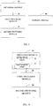
FIG. 4-A is a schematic diagram illustrating a screen state switching process according to implementations. -
FIG. 4-B is a schematic diagram illustrating a screen state switching process according to other implementations. -
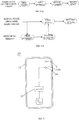
FIG. 5 is a schematic diagram illustrating a terminal device according to implementations. -
FIG. 6 is a cross-sectional view of a terminal device according to implementations. -
FIG. 7 is a cross-sectional view of a terminal device according to other implementations. -
FIG. 8 is a schematic structural diagram illustrating a device for controlling switching of proximity-event detection elements according to implementations. -
FIG. 9 is a schematic structural diagram illustrating a device for controlling switching of proximity-event detection elements according to other implementations. -
FIG. 10 is a schematic structural diagram illustrating a device for controlling switching of proximity-event detection elements according to yet other implementations. - The following describes implementations in detail. Examples of the implementations are illustrated in the accompanying drawings, where the same or like reference numerals represent the same or like elements or elements having the same or similar functions. The implementations described below with reference to the accompanying drawings are exemplary and are merely intended to explain the disclosure rather than limit the disclosure.
- As mentioned in the above, since proximity data is generally collected by a fixed proximity sensor in the terminal device, it is difficult to adapt to varied collection conditions. For example, in a case that the fixed proximity sensor is an infrared sensor, when a screen is in a screen-on state, infrared light emitted by the infrared sensor may cause electrons in the screen to be excited so as to cause a light-transmittance display screen to flicker, thereby interfering with normal display of the light-transmittance display screen. As a result, functionality and quality of service provided by the terminal device may be affected. In addition, the electrons in the display screen and the infrared light are affected by each other, which may reduce accuracy of the proximity data collected.
- To solve above-mentioned conflict between the fixed proximity sensor and the varied collection conditions, in the implementations of the disclosure, different elements for collecting proximity data are set according to different screen states, and therefore for each collection condition there is a corresponding element, which improves the accuracy of the proximity data collected.
- In actual applications, applicant has known that when different elements (for collecting proximity data) are set for different screen states, during switching of the screen states, blocking of the switching of the screen states may occur due to the delay of switching of corresponding elements for detecting screen proximity events. Therefore, in implementations of the disclosure, an optimized method for switching the proximity-event detection elements is further provided to ensure smoothness of the switching of the screen states.
- The following will describe the method for controlling switching of proximity-event detection elements of the implementations of the disclosure with reference to the accompanying drawings. The method is applicable to a terminal device including multiple proximity-event detection elements. The terminal device may be a mobile phone, a tablet computer, a personal digital assistant, a wearable device, or other hardware devices having a display screen. The wearable device may be a smart bracelet, a smart watch, smart glasses, or the like.
-
FIG. 1 is a flow chart illustrating a method for controlling switching of proximity-event detection elements according to implementations. As illustrated inFIG. 1 , the method begins at 101. - At 101, an instruction of switching a screen of a terminal device from a current first state to a second state is obtained.
- The first state and the second state of the screen respectively correspond to different states of the screen (i.e., screen states) of the terminal device. Proximity-data collection conditions are different in the first state and in the second state. In one example, the first state and the second state are respectively a screen-on state and a screen-off state, the screen-off state and the screen-on state, or the like.
- It should be noted that in different application scenarios, different manners are used to obtain the instruction of switching the screen of the terminal device from the current first state to the second state. Examples are as follows.
- In an implementation, as illustrated in
FIG. 2 , the operation at 101 includes operations at 201 and 202. - At 201, a current operation-state feature of the terminal device is detected.
- In one example, the current operation-state feature of the terminal device is used for assisting in determining in advance whether a user wants to switch the screen states. In different screen states, operation-state features to be determined are different. Examples are as follows.
- As one example, if the current screen state is the screen-on state, a corresponding operation-state feature is used for assisting in determining whether to perform a screen-off operation, and thus the current operation-state feature includes a duration that no application runs in the foreground of the terminal device, a duration that no operation is performed on the screen of the terminal device, whether a corresponding screen-off button triggered by a user has been detected, or the like.
- As another example, if the current screen state is the screen-off state, a corresponding operation-state feature is used for assisting in determining whether to light up the screen, and thus the current operation-state feature includes whether a start button of the terminal device is triggered, whether a screen-off gesture inputted by the user has been detected, or the like.
- At 202, the instruction of switching the screen of the terminal device from the current first state to the second state is obtained when the current operation-state feature matches a preset screen-state switching feature.
- It can be understood that different screen states correspond to different operation-state features (for assisting in determining whether to perform switching of the screen states), and accordingly correspond to different preset screen-state switching features. For example, as stated above, when the current screen state is the screen-on state, a corresponding preset screen-state switching feature is that the duration that no operation is performed on the screen of the terminal device reaches a preset duration (e.g., 2 minutes).
- In one example, upon detecting that the current operation-state feature is the preset screen-state switching feature, it can be considered that the current user wants to switch the screen states, so that the screen of the terminal device can be switched from the current first state to the second state.
- In another implementation, as illustrated in
FIG. 3 , the operation at 101 includes operations at 301 and 302. - At 301, power information of the terminal device is obtained.
- In one example, "IntentFilter" and "BroadcastReceiver" are written, "registerReceiver (batteryReceiver, intentFilter)" is registered, wait for an onReceive callback and then parse "intent", so as to obtain the power information of the terminal device.
- At 302, the instruction of switching the screen of the terminal device from the current first state to the second state is obtained when the power information matches preset screen-state switching power information.
- It can be understood that the preset screen-state switching power information corresponds to the current screen state. For example, when the current screen state (i.e., the first state) is the screen-on state, the preset screen-state switching power information includes a relatively low power threshold. That is, when the current screen state is the screen-on state, if the power of the terminal device is less than the relatively low power threshold, the screen of the terminal device is switched from the screen-on state to the screen-off state to improve the endurance of the terminal device. In addition, in order not to affect the use, before the screen is switched from the screen-on state to the screen-off state (i.e., the second state), reminding information is popped up for reminding the user of whether to proceed to perform the switching of the screen states. Upon detecting that the switching of the screen states is rejected by the user, the switching of the screen states is skipped.
- For another example, when the current screen state (i.e., the first state) is the screen-off state, the preset screen-state switching power information includes a relatively high power threshold, for example, five percent (5%) power. That is, when the current screen state is the screen-off state, if the power of the terminal device is greater than the relatively high power threshold, the screen of the terminal device is switched from the screen-off state to the screen-on state (i.e., the second state) to facilitate the use. It can be understood that for the convenience of the user, before switching the screen states according to the power information, authorization information of the user can also be obtained.
- Therefore, based on the above examples, it can be known that the demand for switching of the screen states can be determined ahead of time, such that the switching of the detection elements (for detecting data) corresponding to the screen states can be performed ahead of time, thereby further ensuring smoothness of the switching of the screen states.
- At 102, a pre-established switching thread is invoked to switch a first element corresponding to the first state to a second element corresponding to the second state, where the first element is configured to detect a screen proximity event in the first state and the second element is configured to detect a screen proximity event in the second state.
- It can be understood that time consumed by switching from the first element (for detecting the screen proximity event in the first state) corresponding to the first state to the second element (for detecting the screen proximity event in the second state) corresponding to the second state may lead to blocking of the switching of the screen states. For example, when the screen is switched from the first state to the second state, since the switching from the first element to the second element has not been completed, the switching from the first state to the second state will be paused, which may affect efficiency of the switching of the screen states and thus affect the user experience.
- In at least one implementation, it is further possible to coordinate network resources to a switching thread currently invoked to improve the processing efficiency of the switching thread, for example, network resources for an advertisement thread are released to be allocated to the network resources to the switching thread currently invoked.
- In order to smooth the switching of the screen states, in implementations of the disclosure, a switching thread is pre-established, where the switching thread is configured to control the switching from the first element to the second element. In one example, as illustrated in
FIG. 4-A , if merely the switching from the first element to the second element is taken into account according to the instruction of switching the screen states, a screen-state switching main thread may perform switching from the first element to the second element in the first state. In this case, the screen is not switched to the second state until the switching from the first element to the second element is completed, which may cause the blocking of the switching of the screen states. In contrast, as illustrated inFIG. 4-B , the switching thread is pre-established. After the screen-state switching main thread obtains the instruction of switching the screen of the terminal device from the current first state to the second state, the pre-established switching thread is invoked to switch the first element corresponding to the first state to the second element corresponding to the second state, and thus by means of switching from the first element to the second element by the switching thread, a speed of element switching can be improved, and it can be ensured that the switching of the screen states is not blocked. - In at least one implementation, in order to ensure the stability of control of the switching of the proximity-event detection elements, the proximity-event detection element switching thread is marked as a thread that does not respond to asynchronous signals, that is, the switching thread cannot be interrupted.
- At 103, the screen of the terminal device is switched from the first state to the second state when a switching success notification is obtained from the switching thread.
- In one example, when the switching success notification is obtained from the switching thread, the screen of the terminal device is switched from the first state to the second state. That is, the switching from the first element to the second element has been completed when the screen of the terminal device is switched from the first state to the second state, thereby ensuring the smoothness of the switching of the screen states.
- For better understanding of the method for controlling switching of the proximity-event detection elements in the implementations of the disclosure, the following will describe the implementations in conjunction with specific application scenarios. Examples are as follows.
- In the implementation, the first state is the screen-on state and the second state is the screen-off state, and accordingly the first element is a touch screen proximity sensor and the second element is an infrared proximity sensor.
- As illustrated in
FIG. 5 to FIG. 7 , theterminal device 100 includes atouch screen 103, aninfrared proximity sensor 16, alight sensor 5, and aprocessor 23. Thetouch screen 103 includes adisplay layer 13. Thedisplay layer 13 has adisplay region 1311. Theinfrared proximity sensor 16 is disposed below thedisplay region 1311. Theinfrared proximity sensor 16 is configured to emit infrared light and receive infrared light reflected by an object to detect a distance between the object and theterminal device 100. - The following describes the mobile phone as an example of the
terminal device 100. By setting theinfrared proximity sensor 16 in the mobile phone to determine the distance between the mobile phone and an obstacle and making corresponding adjustments according to the distance, it is helpful to prevent accidental operations and save the power of the mobile phone. For example, when the user makes or answers a call and raises the mobile phone close to the head, theinfrared proximity sensor 16 generates detection information by calculating a time length from a time point at which a transmitter emits infrared light to a time point at which a receiver receives reflected infrared light, and theprocessor 23 turns off thedisplay layer 13 according to the detection information. Thereafter, when the mobile phone is far from the head, theprocessor 23 lights up thedisplay layer 13 again according to detection information fed back by theinfrared proximity sensor 16. - In one example, the
display layer 13 is an organic light-emitting diode (OLED) display layer. - As illustrated in
FIG. 7 , in one example, thetouch screen 103 further includes a light-transmission cover plate 11 and atouch layer 12. The light-transmission cover plate 11 is arranged on thetouch layer 12. Thetouch layer 12 is arranged on thedisplay layer 13, and anupper surface 131 of thedisplay layer 13 faces thetouch layer 12. A visible-light transmittance and an infrared-light transmittance of the light-transmission cover plate 11 and thetouch layer 12 are both over 90%. - The
touch layer 12 is mainly configured to receive proximity signal inputted by the user and transmit the proximity signal to a circuit board for data processing. That is, thetouch layer 12 can support the touch screen to work as a touch screen proximity sensor, so as to obtain a certain position where the user touches thetouch layer 12. It should be noted that thetouch layer 12 being arranged on thedisplay layer 13 refers to that thetouch layer 12 is in contact with thedisplay layer 13. For example, thetouch layer 12 is attached to thedisplay layer 13 by adopting In-Cell or On-Cell technology, and by attaching thetouch layer 12 to thedisplay layer 13, the weight of thedisplay layer 13 and the overall thickness of thedisplay layer 13 can be reduced. Alternatively, thetouch layer 12 being arranged on thedisplay layer 13 also means that thetouch layer 12 is arranged above thedisplay layer 13 and thetouch layer 12 and thedisplay layer 13 are spaced apart from each other. - In addition, the light-
transmission cover plate 11 being arranged on thetouch layer 12 can effectively protect thetouch layer 12 and internal structures of thetouch layer 12, and avoid damage to thetouch layer 12 and thedisplay layer 13 caused by external forces. The visible-light transmittance and the infrared-light transmittance of the light-transmission cover plate 11 and thetouch layer 12 are both over 90%, which is not only beneficial to thedisplay layer 13 to better display content, but also beneficial to theinfrared proximity sensor 16 disposed below thedisplay layer 13 to stably emit and receive infrared light, thereby ensuring the normal operation of theinfrared proximity sensor 16. - In one example, the
infrared proximity sensor 16 is configured to acquire proximity data when the screen is in the screen-off state, and thetouch screen 103 is configured to acquire proximity data when the screen is in the screen-on state. Therefore, when the instruction of switching the screen states is obtained, the touch screen proximity sensor corresponding to the screen-on state is switched to the infrared proximity sensor corresponding to the screen-off state. - In at least one implementation, the first state is the screen-off state and the second state is the screen-on state, and accordingly the first element is the infrared proximity sensor and the second element is the touch screen proximity sensor.
- Referring back to
FIG. 5 to FIG. 7 , the terminal device includes the infrared proximity sensor and the touch screen having a proximity recognition function. The touch screen is used as a touch screen proximity sensor to recognize proximity events. - In one example, the
infrared proximity sensor 16 is configured to acquire proximity data when the screen is in the screen-off state, and thetouch screen 103 is configured to acquire proximity data when the screen is in the screen-on state. Therefore, when the instruction of switching the screen states is obtained, the infrared proximity sensor corresponding to the screen-off state is switched to the touch screen proximity sensor corresponding to the screen-on state. - According to the method for controlling switching of proximity-event detection elements, the instruction of switching the screen of the terminal device from the current first state to the second state is obtained. The first element corresponding to the first state is switched to the second element corresponding to the second state by invoking the pre-established switching thread, where the first element is configured to detect the screen proximity event in the first state and the second element is configured to detect the screen proximity event in the second state. The screen of the terminal device is switched from the first state to the second state when the switching success notification is obtained from the switching thread. With aid of the method, different elements are configured to collect the proximity data when the screen is in different states, which improves the accuracy of the proximity data collected, and avoids the blocking of switching of the screen states caused by the delay of the switching of the elements for detecting the screen proximity events during switching of the screen states, thereby improving the smoothness of the switching of the screen states and improving the user experience.
- Implementations of the disclosure further provide a device for controlling switching of proximity-event detection elements.
FIG. 8 is a schematic structural diagram illustrating a device for controlling switching of proximity-event detection elements according to implementations. As illustrated inFIG. 8 , the device includes an obtainingmodule 10, afirst switching module 20, and asecond switching module 30. - The obtaining
module 10 is configured to obtain an instruction of switching a screen of a terminal device from a current first state to a second state. - The
first switching module 20 is configured to switch a first element corresponding to the first state to a second element corresponding to the second state by invoking a pre-established switching thread, where the first element is configured to detect a screen proximity event in the first state and the second element is configured to detect a screen proximity event in the second state. - The
second switching module 30 is configured to switch the screen of the terminal device from the first state to the second state when a switching success notification is obtained from the switching thread. - In at least one implementation, in terms of switching the first element corresponding to the first state to the second element corresponding to the second state, the
first switching module 20 is configured to: switch a touch screen proximity sensor corresponding to a screen-on state to an infrared proximity sensor corresponding to a screen-off state when the first state is the screen-on state and the second state is the screen-off state; or switch the infrared proximity sensor corresponding to the screen-off state to the touch screen proximity sensor corresponding to the screen-on state when the first state is the screen-off state and the second state is the screen-on state. - In at least one implementation, as illustrated in
FIG. 9 , based onFIG. 8 , the device further includes a markingmodule 40. The markingmodule 40 is configured to mark the pre-established proximity-event detection element switching thread as a thread that does not respond to asynchronous signals. - In at least one implementation, as illustrated in
FIG. 10 , based onFIG. 8 , the obtainingmodule 10 further includes a detectingunit 11 and a detectingunit 12. - The detecting
unit 11 is configured to detect a current operation-state feature of the terminal device. - The obtaining
unit 12 is configured to obtain the instruction of switching the screen of the terminal device from the current first state to the second state upon detecting that the current operation-state feature is a preset screen-state switching feature. - In another implementation, the detecting
unit 11 is configured to obtain power information of the terminal device, and the obtainingunit 12 is configured to obtain the instruction of switching the screen of the terminal device from the current first state to the second state upon determining that the power information matches preset screen-state switching power information. - In at least one implementation, in terms of obtaining the instruction of switching the screen of the terminal device from the current first state to the second state, the obtaining
unit 12 is configured to: obtain the instruction of switching the screen of the terminal device from a screen-on state to a screen-off state when the first state is the screen-on state and the power information is less than the preset screen-state switching power information. - In another implementation, in terms of obtaining the instruction of switching the screen of the terminal device from the current first state to the second state, the obtaining
unit 12 is configured to: obtain the instruction of switching the screen of the terminal device from a screen-off state to a screen-on state when the first state is the screen-off state and the power information is greater than the preset screen-state switching power information. - In at least one implementation, the device further includes a coordinating module. The coordinating module is configured to coordinate network resources to the pre-established switching thread currently invoked.
- It should be noted that the explanation of the method for controlling switching of proximity-event detection elements in the foregoing implementations is also applicable to the device for controlling switching of proximity-event detection elements, and details are not described herein again.
- According to the device for controlling switching of proximity-event detection elements, the instruction of switching the screen of the terminal device from the current first state to the second state is obtained. The first element corresponding to the first state is switched to the second element corresponding to the second state by invoking the pre-established switching thread, where the first element is configured to detect the screen proximity event in the first state and the second element is configured to detect the screen proximity event in the second state. The screen of the terminal device is switched from the first state to the second state when the switching success notification is obtained from the switching thread. With aid of the method, different elements are configured to collect the proximity data when the screen is in different states, which improves the accuracy of the proximity data collected, and avoids the blocking of switching of the screen states caused by the delay of the switching of the elements for detecting the screen proximity events during switching of the screen states, thereby improving the smoothness of the switching of the screen states and improving the user experience.
- Implementations of the disclosure further provide a terminal device. The terminal device includes a processor, a memory, and computer programs stored in the memory and executable on the processor. The computer programs, when executed by the processor, are operable with the processor to perform the method for controlling switching of proximity-event detection elements described above.
- Implementations of the disclosure further provide a computer readable storage medium storing computer programs. The computer programs, when executed by a processor, are operable with the processor to perform the method controlling switching of proximity-event detection elements described above.
- The reference term "an implementation", "some implementations", "implementation", "specific implementation", or "some implementations" referred to herein means that a particular feature, structure, material, or characteristic described in conjunction with the implementation or implementation may be contained in at least one implementation or implementation of the present disclosure. The phrase appearing in various places in the specification does not necessarily refer to the same implementation or implementation. The particular feature, structure, material, or characteristic described may be properly combined in any one or more implementations or implementations. In addition, when the implementation or implementation is not mutually exclusive with other implementations or implementations, it is expressly and implicitly understood by those skilled in the art that an implementation described herein may be combined with other implementations or implementations.
- In addition, terms "first", "second", and the like are only used for description and cannot be understood as explicitly or implicitly indicating relative importance or implicitly indicating the number of technical features referred to herein. Therefore, features restricted by terms "first", "second", and the like can explicitly or implicitly include at least one of the features. In the context of the disclosure, unless stated otherwise, "multiple" refers to "at least two", such as two, three, and the like.
- Any process or method illustrated in a flow chart or herein in other manners can be understood as a module, a fragment, or a portion of codes that include one or more executable instructions for implementing a particular logical function or operations of a process. The scope of the implementations includes additional implementations in which the functions may be performed out of the order illustrated or discussed. For example, the functions can be performed in a substantially simultaneous manner or in the reverse order according to the functions involved, which should be understood by those skilled in the art.
- Logics and/or steps illustrated in the flow charts or described herein in other ways, can be considered as a sequencing table of executable instructions for realizing logical functions, which can be embodied in any computer readable medium to be used by an instruction execution system, a device, or an apparatus (e.g., a computer-based system, a system including a processing module, or other systems that can extract an instruction which is obtained from the instruction execution system, device, or apparatus), or to be used in combination with the instruction execution system, device, or apparatus. In terms of this specification, the "computer readable medium" may be any device that includes or stores communicating programs, propagation or transmission programs used by the instruction execution system, device, or apparatus or can be used in combination with the instruction execution system, device or, apparatus. In particular, the computer readable medium (illustrated in a non-exhaustive list) may include: an electrical connection part (control method) having one or more wires, a portable computer disk cartridge (magnetic device), a random access memory (RAM), a read-only memory (ROM), an erasable programmable read-only memory (EPROM or flash memory), an optical fiber device, and a portable compact disc read-only memory (CDROM). In addition, the computer readable medium even can be paper or other appropriate medium on which the programs are printed, where the programs can be electronically obtained as follows. An optical scanning is conducted on the paper or other medium, followed by editing, interpreting, or processing in other appropriate mode. The programs are stored in a computer memory.
- It should be understood that all parts of the implementations can be realized via hardware, software, firmware, or a combination thereof. In the above implementations, multiple operations or methods can be implemented by software or firmware that is stored in a memory and executed by a proper instruction execution system. For example, if the multiple operations or methods are implemented by hardware, as in another implementation, the multiple operations or methods can be implemented with any of the following technologies or a combination thereof known in the art: a discrete logic circuit with a logic gate circuit for realizing logic functions on data signals, a dedicated integrated circuit with an appropriate combined logic gate circuit, a programmable gate array (PGA), a field programmable gate array (FPGA), and so on.
- It should be understood by those of ordinary skill in the art that all or part of operations of the method of the above implementations can be implemented by instructing relevant hardware via a program, the program can be stored in a computer-readable storage medium, and when the program is executed, one of operations or a combination of the operations of the method implementations is executed.
- Moreover, the functional units in the implementations may be integrated in one processing module, or the units separately and physically exist, or two or more units are integrated in one module. The above-mentioned integrated module may be realized in the form of hardware or a software functional module. When the integrated module is realized in the form of a software functional module and sold or used as an independent product, it can also be stored in a computer-readable storage medium.
- The aforementioned storage medium may be an ROM, a magnetic disc, or an optical disc, or the like.
- Although some implementations are illustrated and described above, it should be understood that the implementations are exemplary rather than limiting the present disclosure. Various changes, modifications, substitutions, and variations could be made to the implementations by those of ordinary skilled in the art within the scope of the disclosure.
Claims (20)
- A method for controlling switching of proximity-event detection elements, comprising:obtaining an instruction of switching a screen of a terminal device from a current first state to a second state;switching a first element corresponding to the first state to a second element corresponding to the second state by invoking a pre-established switching thread, wherein the first element is configured to detect a screen proximity event in the first state and the second element is configured to detect a screen proximity event in the second state; andswitching the screen of the terminal device from the first state to the second state in response to obtaining a switching success notification from the switching thread.
- The method of claim 1, wherein
the first state is a screen-on state and the second state is a screen-off state, and switching the first element corresponding to the first state to the second element corresponding to the second state comprises:switching a touch screen proximity sensor corresponding to the screen-on state to an infrared proximity sensor corresponding to the screen-off state; orthe first state is the screen-off state and the second state is the screen-on state, and switching the first element corresponding to the first state to the second element corresponding to the second state comprises:
switching the infrared proximity sensor corresponding to the screen-off state to the touch screen proximity sensor corresponding to the screen-on state. - The method of claim 1 or 2, comprising:
prior to invoking the pre-established proximity-event detection element switching thread,
marking the pre-established proximity-event detection element switching thread as a thread that does not respond to asynchronous signals. - The method of any of claims 1 to 3, wherein obtaining the instruction of switching the screen of the terminal device from the current first state to the second state comprises:detecting a current operation-state feature of the terminal device; andobtaining the instruction of switching the screen of the terminal device from the current first state to the second state in response to detecting that the current operation-state feature matches a preset screen-state switching feature.
- The method of any of claims 1 to 3, wherein obtaining the instruction of switching the screen of the terminal device from the current first state to the second state comprises:obtaining power information of the terminal device; andobtaining the instruction of switching the screen of the terminal device from the current first state to the second state in response to determining that the power information matches preset screen-state switching power information.
- The method of claim 5, wherein obtaining the instruction of switching the screen of the terminal device from the current first state to the second state in response to determining that the power information matches the preset screen-state switching power information comprises:
obtaining the instruction of switching the screen of the terminal device from a screen-on state to a screen-off state in condition of the first state being the screen-on state in response to the power information being less than the preset screen-state switching power information. - The method of claim 5, wherein obtaining the instruction of switching the screen of the terminal device from the current first state to the second state in response to determining that the power information matches the preset screen-state switching power information comprises:
obtaining the instruction of switching the screen of the terminal device from a screen-off state to a screen-on state in condition of the first state being the screen-off state in response to the power information being greater than the preset screen-state switching power information. - The method of any of claims 1 to 7, comprising:
after invoking the pre-established switching thread,
coordinating network resources to the pre-established switching thread currently invoked. - A device for controlling switching of proximity-event detection elements, comprising:an obtaining module configured to obtain an instruction of switching a screen of a terminal device from a current first state to a second state;a first switching module configured to switch a first element corresponding to the first state to a second element corresponding to the second state by invoking a pre-established switching thread, wherein the first element is configured to detect a screen proximity event in the first state and the second element is configured to detect a screen proximity event in the second state; anda second switching module configured to switch the screen of the terminal device from the first state to the second state in response to obtaining a switching success notification from the switching thread.
- The device of claim 9, wherein the first switching module configured to switch the first element corresponding to the first state to the second element corresponding to the second state is configured to:switch a touch screen proximity sensor corresponding to a screen-on state to an infrared proximity sensor corresponding to a screen-off state when the first state is the screen-on state and the second state is the screen-off state; orswitch the infrared proximity sensor corresponding to the screen-off state to the touch screen proximity sensor corresponding to the screen-on state when the first state is the screen-off state and the second state is the screen-on state.
- The device of claim 9 or 10, comprising a marking module configured to:
mark the pre-established proximity-event detection element switching thread as a thread that does not respond to asynchronous signals. - The device of any of claims 9 to 11, wherein the obtaining module comprises:a detecting unit configured to detect a current operation-state feature of the terminal device; andan obtaining unit configured to obtain the instruction of switching the screen of the terminal device from the current first state to the second state in response to detecting that the current operation-state feature is a preset screen-state switching feature.
- The device of any of claims 9 to 11, wherein the obtaining module comprises:a detecting unit configured to obtain power information of the terminal device; andan obtaining unit configured to obtain the instruction of switching the screen of the terminal device from the current first state to the second state in response to determining that the power information matches preset screen-state switching power information.
- The device of claim 13, wherein the obtaining unit configured to obtain the instruction of switching the screen of the terminal device from the current first state to the second state is configured to:obtain the instruction of switching the screen of the terminal device from a screen-on state to a screen-off state in condition of the first state being the screen-on state in response to the power information being less than the preset screen-state switching power information.
- The device of claim 13, wherein the obtaining unit configured to obtain the instruction of switching the screen of the terminal device from the current first state to the second state is configured to:
obtain the instruction of switching the screen of the terminal device from a screen-off state to a screen-on state in condition of the first state being the screen-off state in response to the power information being greater than the preset screen-state switching power information. - The device of any of claims 9 to 15, comprising:
a coordinating module configured to:
coordinate network resources to the pre-established switching thread currently invoked. - A terminal device comprising:a processor;a memory; andcomputer programs stored in the memory and executable on the processor, wherein the computer programs, when executed by the processor, are operable with the processor to perform the method of any of claims 1 to 8.
- The terminal device of claim 17, comprising:
the infrared proximity sensor configured to obtain proximity data in the screen-off state. - The terminal device of claim 17, comprising:
a touch screen configured to obtain proximity data in the screen-on state. - A computer readable storage medium storing computer programs, wherein the computer programs, when executed by a processor, are operable with the processor to perform the method of any of claims 1 to 8.
Applications Claiming Priority (2)
| Application Number | Priority Date | Filing Date | Title |
|---|---|---|---|
| CN201810961363.XA CN109271019B (en) | 2018-08-22 | 2018-08-22 | Proximity event detection element switching control method and device |
| PCT/CN2019/094200 WO2020038122A1 (en) | 2018-08-22 | 2019-07-01 | Method and device for switching and controlling an approaching event detection element |
Publications (3)
| Publication Number | Publication Date |
|---|---|
| EP3828684A1 true EP3828684A1 (en) | 2021-06-02 |
| EP3828684A4 EP3828684A4 (en) | 2021-09-22 |
| EP3828684B1 EP3828684B1 (en) | 2024-04-24 |
Family
ID=65154021
Family Applications (1)
| Application Number | Title | Priority Date | Filing Date |
|---|---|---|---|
| EP19851070.3A Active EP3828684B1 (en) | 2018-08-22 | 2019-07-01 | Method and device for controlling switching of proximity-event detection elements |
Country Status (4)
| Country | Link |
|---|---|
| US (1) | US20210165479A1 (en) |
| EP (1) | EP3828684B1 (en) |
| CN (1) | CN109271019B (en) |
| WO (1) | WO2020038122A1 (en) |
Families Citing this family (8)
| Publication number | Priority date | Publication date | Assignee | Title |
|---|---|---|---|---|
| US11663628B2 (en) | 2012-05-14 | 2023-05-30 | Iqzone, Inc. | Systems and methods for unobtrusively displaying media content on portable devices |
| US11599907B2 (en) | 2012-05-14 | 2023-03-07 | Iqzone, Inc. | Displaying media content on portable devices based upon user interface state transitions |
| CN109271019B (en) * | 2018-08-22 | 2020-07-10 | Oppo广东移动通信有限公司 | Proximity event detection element switching control method and device |
| CN110138974B (en) * | 2019-05-20 | 2021-06-01 | 西安易朴通讯技术有限公司 | Screen control method, device, equipment and computer readable storage medium |
| US11736776B2 (en) | 2019-10-25 | 2023-08-22 | Iqzone, Inc. | Monitoring operating system methods to facilitate unobtrusive display of media content on portable devices |
| CN114285935B (en) * | 2020-09-17 | 2023-09-15 | 南京酷派软件技术有限公司 | Terminal control method, device, storage medium and electronic equipment |
| CN115701582A (en) * | 2021-08-02 | 2023-02-10 | 北京科益虹源光电技术有限公司 | Laser state switching method and device |
| CN116805929A (en) * | 2023-08-28 | 2023-09-26 | 深圳海普瑞丽科技有限公司 | A network analyzer port multiplexing system, method and storage medium |
Family Cites Families (19)
| Publication number | Priority date | Publication date | Assignee | Title |
|---|---|---|---|---|
| US20090037756A1 (en) * | 2007-07-31 | 2009-02-05 | Lundquist David T | System and Method for Suspending Operation of a Mobile Unit |
| US8723811B2 (en) * | 2008-03-21 | 2014-05-13 | Lg Electronics Inc. | Mobile terminal and screen displaying method thereof |
| US9030407B2 (en) * | 2011-12-21 | 2015-05-12 | Nokia Technologies Oy | User gesture recognition |
| CN203311399U (en) * | 2013-05-20 | 2013-11-27 | 北京百纳威尔科技有限公司 | Mobile phone touch screen with proximity sensing function |
| CN104516474B (en) * | 2013-10-08 | 2017-12-26 | 联想(北京)有限公司 | A kind of information processing method and electronic equipment |
| CN103929538A (en) * | 2014-04-09 | 2014-07-16 | 惠州Tcl移动通信有限公司 | Mobile terminal call-answering method and system based on proximity sensor |
| US20150330772A1 (en) * | 2014-05-15 | 2015-11-19 | Nataporn Charusabha | Proximity Sensor Having a Daughterboard-Mounted Light Detector |
| CN104007878B (en) * | 2014-05-16 | 2017-01-25 | 广东欧珀移动通信有限公司 | Method and device for preventing error operation on touch screen terminal |
| CN104750421A (en) * | 2015-04-20 | 2015-07-01 | 深圳市欧珀通信软件有限公司 | Touch screen operation method and device for mobile terminal |
| CN106020423A (en) * | 2016-05-25 | 2016-10-12 | 努比亚技术有限公司 | Screen control device and method for terminal |
| CN106200989B (en) * | 2016-09-08 | 2019-11-12 | 广东小天才科技有限公司 | Method and device for brightening screen of mobile terminal |
| CN206292950U (en) * | 2016-09-13 | 2017-06-30 | 东莞市联臣电子科技股份有限公司 | A kind of Intelligent eyesight protection device |
| CN106873879B (en) * | 2017-01-25 | 2019-10-29 | 维沃移动通信有限公司 | A kind of electronic equipment and put out screen processing method, device |
| CN107943345B (en) * | 2017-11-22 | 2020-10-02 | Oppo广东移动通信有限公司 | Calibration method, device, storage medium and electronic device for proximity sensor |
| CN107908313B (en) * | 2017-11-22 | 2021-04-13 | Oppo广东移动通信有限公司 | Control method of electronic device and electronic device |
| CN110581904B (en) * | 2018-06-11 | 2021-01-15 | Oppo广东移动通信有限公司 | Control method, control device, electronic device, and storage medium |
| CN109088961B (en) * | 2018-06-15 | 2021-03-02 | Oppo广东移动通信有限公司 | Sensor control circuit and electronic device |
| CN109271019B (en) * | 2018-08-22 | 2020-07-10 | Oppo广东移动通信有限公司 | Proximity event detection element switching control method and device |
| CN109388285A (en) * | 2018-09-25 | 2019-02-26 | Oppo广东移动通信有限公司 | Proximity detection mode switching method and device, electronic equipment and storage medium |
-
2018
- 2018-08-22 CN CN201810961363.XA patent/CN109271019B/en active Active
-
2019
- 2019-07-01 WO PCT/CN2019/094200 patent/WO2020038122A1/en not_active Ceased
- 2019-07-01 EP EP19851070.3A patent/EP3828684B1/en active Active
-
2021
- 2021-02-12 US US17/175,587 patent/US20210165479A1/en not_active Abandoned
Also Published As
| Publication number | Publication date |
|---|---|
| US20210165479A1 (en) | 2021-06-03 |
| CN109271019A (en) | 2019-01-25 |
| CN109271019B (en) | 2020-07-10 |
| EP3828684B1 (en) | 2024-04-24 |
| WO2020038122A1 (en) | 2020-02-27 |
| EP3828684A4 (en) | 2021-09-22 |
Similar Documents
| Publication | Publication Date | Title |
|---|---|---|
| EP3828684A1 (en) | Method and device for switching and controlling an approaching event detection element | |
| US11869974B2 (en) | Electronic device including light detection device and operation method thereof | |
| US10491949B2 (en) | Bullet screen posting method and mobile terminal | |
| EP4401394B1 (en) | Ambient light detection method and terminal | |
| US10372326B2 (en) | Mobile terminal device, operation method, program, and storage medium | |
| US10558835B2 (en) | Electronic device and method for acquiring fingerprint information | |
| US20160345113A1 (en) | Method of recognizing surrounding environment and electronic device for the same | |
| EP2840462A1 (en) | Method and apparatus for saving battery of portable terminal | |
| KR102209910B1 (en) | Coordinate measuring apparaturs which measures input position of coordinate indicating apparatus and method for controlling thereof | |
| KR20180005833A (en) | Electronic device including integrated sensor and operating method thereof | |
| KR20150006180A (en) | Method for controlling chatting window and electronic device implementing the same | |
| CN105488464A (en) | Fingerprint identification method and fingerprint identification apparatus | |
| CN108881645B (en) | Screen control method and device for mobile phone call | |
| US20130100061A1 (en) | Mobile terminal and controlling method thereof | |
| WO2019019835A1 (en) | Method and device for responding to blank screen gesture, and storage medium and mobile terminal | |
| CN103513788B (en) | Based on the gesture identification method of gyro sensor, system and mobile terminal | |
| CN109240541B (en) | Screen false touch prevention method and device of electronic equipment and electronic equipment | |
| CN108646959A (en) | Screen control method, device and mobile terminal | |
| US10159046B2 (en) | Mobile terminal device | |
| JP2017525076A (en) | Character identification method, apparatus, program, and recording medium | |
| CN107884764A (en) | Approach state detection method, device, storage medium and electronic equipment | |
| KR101952342B1 (en) | Off-center sensor target region | |
| CN106791086B (en) | Control method of mobile terminal and mobile terminal | |
| CN106020447B (en) | Method and system for adjusting parameters of proximity sensor of touch electronic equipment | |
| CN109254689B (en) | Proximity detection method and device |
Legal Events
| Date | Code | Title | Description |
|---|---|---|---|
| STAA | Information on the status of an ep patent application or granted ep patent |
Free format text: STATUS: THE INTERNATIONAL PUBLICATION HAS BEEN MADE |
|
| PUAI | Public reference made under article 153(3) epc to a published international application that has entered the european phase |
Free format text: ORIGINAL CODE: 0009012 |
|
| STAA | Information on the status of an ep patent application or granted ep patent |
Free format text: STATUS: REQUEST FOR EXAMINATION WAS MADE |
|
| 17P | Request for examination filed |
Effective date: 20210226 |
|
| AK | Designated contracting states |
Kind code of ref document: A1 Designated state(s): AL AT BE BG CH CY CZ DE DK EE ES FI FR GB GR HR HU IE IS IT LI LT LU LV MC MK MT NL NO PL PT RO RS SE SI SK SM TR |
|
| A4 | Supplementary search report drawn up and despatched |
Effective date: 20210823 |
|
| RIC1 | Information provided on ipc code assigned before grant |
Ipc: G06F 1/16 20060101ALI20210817BHEP Ipc: G06F 3/0488 20130101AFI20210817BHEP |
|
| DAV | Request for validation of the european patent (deleted) | ||
| DAX | Request for extension of the european patent (deleted) | ||
| REG | Reference to a national code |
Ref country code: DE Ref legal event code: R079 Free format text: PREVIOUS MAIN CLASS: G06F0003048700 Ipc: G06F0003048800 Ref document number: 602019051063 Country of ref document: DE |
|
| GRAP | Despatch of communication of intention to grant a patent |
Free format text: ORIGINAL CODE: EPIDOSNIGR1 |
|
| STAA | Information on the status of an ep patent application or granted ep patent |
Free format text: STATUS: GRANT OF PATENT IS INTENDED |
|
| RIC1 | Information provided on ipc code assigned before grant |
Ipc: G06F 1/3212 20190101ALI20231231BHEP Ipc: G06F 1/3231 20190101ALI20231231BHEP Ipc: G06F 1/16 20060101ALI20231231BHEP Ipc: G06F 3/0488 20130101AFI20231231BHEP |
|
| INTG | Intention to grant announced |
Effective date: 20240129 |
|
| GRAS | Grant fee paid |
Free format text: ORIGINAL CODE: EPIDOSNIGR3 |
|
| GRAA | (expected) grant |
Free format text: ORIGINAL CODE: 0009210 |
|
| STAA | Information on the status of an ep patent application or granted ep patent |
Free format text: STATUS: THE PATENT HAS BEEN GRANTED |
|
| AK | Designated contracting states |
Kind code of ref document: B1 Designated state(s): AL AT BE BG CH CY CZ DE DK EE ES FI FR GB GR HR HU IE IS IT LI LT LU LV MC MK MT NL NO PL PT RO RS SE SI SK SM TR |
|
| REG | Reference to a national code |
Ref country code: GB Ref legal event code: FG4D |
|
| REG | Reference to a national code |
Ref country code: CH Ref legal event code: EP |
|
| REG | Reference to a national code |
Ref country code: DE Ref legal event code: R096 Ref document number: 602019051063 Country of ref document: DE |
|
| REG | Reference to a national code |
Ref country code: IE Ref legal event code: FG4D |
|
| REG | Reference to a national code |
Ref country code: LT Ref legal event code: MG9D |
|
| REG | Reference to a national code |
Ref country code: NL Ref legal event code: MP Effective date: 20240424 |
|
| REG | Reference to a national code |
Ref country code: AT Ref legal event code: MK05 Ref document number: 1680328 Country of ref document: AT Kind code of ref document: T Effective date: 20240424 |
|
| PG25 | Lapsed in a contracting state [announced via postgrant information from national office to epo] |
Ref country code: NL Free format text: LAPSE BECAUSE OF FAILURE TO SUBMIT A TRANSLATION OF THE DESCRIPTION OR TO PAY THE FEE WITHIN THE PRESCRIBED TIME-LIMIT Effective date: 20240424 |
|
| PG25 | Lapsed in a contracting state [announced via postgrant information from national office to epo] |
Ref country code: NL Free format text: LAPSE BECAUSE OF FAILURE TO SUBMIT A TRANSLATION OF THE DESCRIPTION OR TO PAY THE FEE WITHIN THE PRESCRIBED TIME-LIMIT Effective date: 20240424 |
|
| PG25 | Lapsed in a contracting state [announced via postgrant information from national office to epo] |
Ref country code: IS Free format text: LAPSE BECAUSE OF FAILURE TO SUBMIT A TRANSLATION OF THE DESCRIPTION OR TO PAY THE FEE WITHIN THE PRESCRIBED TIME-LIMIT Effective date: 20240824 |
|
| PG25 | Lapsed in a contracting state [announced via postgrant information from national office to epo] |
Ref country code: BG Free format text: LAPSE BECAUSE OF FAILURE TO SUBMIT A TRANSLATION OF THE DESCRIPTION OR TO PAY THE FEE WITHIN THE PRESCRIBED TIME-LIMIT Effective date: 20240424 |
|
| PG25 | Lapsed in a contracting state [announced via postgrant information from national office to epo] |
Ref country code: FI Free format text: LAPSE BECAUSE OF FAILURE TO SUBMIT A TRANSLATION OF THE DESCRIPTION OR TO PAY THE FEE WITHIN THE PRESCRIBED TIME-LIMIT Effective date: 20240424 Ref country code: HR Free format text: LAPSE BECAUSE OF FAILURE TO SUBMIT A TRANSLATION OF THE DESCRIPTION OR TO PAY THE FEE WITHIN THE PRESCRIBED TIME-LIMIT Effective date: 20240424 |
|
| PG25 | Lapsed in a contracting state [announced via postgrant information from national office to epo] |
Ref country code: GR Free format text: LAPSE BECAUSE OF FAILURE TO SUBMIT A TRANSLATION OF THE DESCRIPTION OR TO PAY THE FEE WITHIN THE PRESCRIBED TIME-LIMIT Effective date: 20240725 |
|
| PG25 | Lapsed in a contracting state [announced via postgrant information from national office to epo] |
Ref country code: PT Free format text: LAPSE BECAUSE OF FAILURE TO SUBMIT A TRANSLATION OF THE DESCRIPTION OR TO PAY THE FEE WITHIN THE PRESCRIBED TIME-LIMIT Effective date: 20240826 |
|
| PG25 | Lapsed in a contracting state [announced via postgrant information from national office to epo] |
Ref country code: ES Free format text: LAPSE BECAUSE OF FAILURE TO SUBMIT A TRANSLATION OF THE DESCRIPTION OR TO PAY THE FEE WITHIN THE PRESCRIBED TIME-LIMIT Effective date: 20240424 |
|
| PG25 | Lapsed in a contracting state [announced via postgrant information from national office to epo] |
Ref country code: AT Free format text: LAPSE BECAUSE OF FAILURE TO SUBMIT A TRANSLATION OF THE DESCRIPTION OR TO PAY THE FEE WITHIN THE PRESCRIBED TIME-LIMIT Effective date: 20240424 |
|
| PG25 | Lapsed in a contracting state [announced via postgrant information from national office to epo] |
Ref country code: PL Free format text: LAPSE BECAUSE OF FAILURE TO SUBMIT A TRANSLATION OF THE DESCRIPTION OR TO PAY THE FEE WITHIN THE PRESCRIBED TIME-LIMIT Effective date: 20240424 |
|
| PG25 | Lapsed in a contracting state [announced via postgrant information from national office to epo] |
Ref country code: LV Free format text: LAPSE BECAUSE OF FAILURE TO SUBMIT A TRANSLATION OF THE DESCRIPTION OR TO PAY THE FEE WITHIN THE PRESCRIBED TIME-LIMIT Effective date: 20240424 |
|
| PG25 | Lapsed in a contracting state [announced via postgrant information from national office to epo] |
Ref country code: PT Free format text: LAPSE BECAUSE OF FAILURE TO SUBMIT A TRANSLATION OF THE DESCRIPTION OR TO PAY THE FEE WITHIN THE PRESCRIBED TIME-LIMIT Effective date: 20240826 Ref country code: PL Free format text: LAPSE BECAUSE OF FAILURE TO SUBMIT A TRANSLATION OF THE DESCRIPTION OR TO PAY THE FEE WITHIN THE PRESCRIBED TIME-LIMIT Effective date: 20240424 Ref country code: NO Free format text: LAPSE BECAUSE OF FAILURE TO SUBMIT A TRANSLATION OF THE DESCRIPTION OR TO PAY THE FEE WITHIN THE PRESCRIBED TIME-LIMIT Effective date: 20240724 Ref country code: LV Free format text: LAPSE BECAUSE OF FAILURE TO SUBMIT A TRANSLATION OF THE DESCRIPTION OR TO PAY THE FEE WITHIN THE PRESCRIBED TIME-LIMIT Effective date: 20240424 Ref country code: IS Free format text: LAPSE BECAUSE OF FAILURE TO SUBMIT A TRANSLATION OF THE DESCRIPTION OR TO PAY THE FEE WITHIN THE PRESCRIBED TIME-LIMIT Effective date: 20240824 Ref country code: HR Free format text: LAPSE BECAUSE OF FAILURE TO SUBMIT A TRANSLATION OF THE DESCRIPTION OR TO PAY THE FEE WITHIN THE PRESCRIBED TIME-LIMIT Effective date: 20240424 Ref country code: GR Free format text: LAPSE BECAUSE OF FAILURE TO SUBMIT A TRANSLATION OF THE DESCRIPTION OR TO PAY THE FEE WITHIN THE PRESCRIBED TIME-LIMIT Effective date: 20240725 Ref country code: FI Free format text: LAPSE BECAUSE OF FAILURE TO SUBMIT A TRANSLATION OF THE DESCRIPTION OR TO PAY THE FEE WITHIN THE PRESCRIBED TIME-LIMIT Effective date: 20240424 Ref country code: ES Free format text: LAPSE BECAUSE OF FAILURE TO SUBMIT A TRANSLATION OF THE DESCRIPTION OR TO PAY THE FEE WITHIN THE PRESCRIBED TIME-LIMIT Effective date: 20240424 Ref country code: BG Free format text: LAPSE BECAUSE OF FAILURE TO SUBMIT A TRANSLATION OF THE DESCRIPTION OR TO PAY THE FEE WITHIN THE PRESCRIBED TIME-LIMIT Effective date: 20240424 Ref country code: AT Free format text: LAPSE BECAUSE OF FAILURE TO SUBMIT A TRANSLATION OF THE DESCRIPTION OR TO PAY THE FEE WITHIN THE PRESCRIBED TIME-LIMIT Effective date: 20240424 Ref country code: RS Free format text: LAPSE BECAUSE OF FAILURE TO SUBMIT A TRANSLATION OF THE DESCRIPTION OR TO PAY THE FEE WITHIN THE PRESCRIBED TIME-LIMIT Effective date: 20240724 |
|
| PG25 | Lapsed in a contracting state [announced via postgrant information from national office to epo] |
Ref country code: DK Free format text: LAPSE BECAUSE OF FAILURE TO SUBMIT A TRANSLATION OF THE DESCRIPTION OR TO PAY THE FEE WITHIN THE PRESCRIBED TIME-LIMIT Effective date: 20240424 |
|
| PG25 | Lapsed in a contracting state [announced via postgrant information from national office to epo] |
Ref country code: EE Free format text: LAPSE BECAUSE OF FAILURE TO SUBMIT A TRANSLATION OF THE DESCRIPTION OR TO PAY THE FEE WITHIN THE PRESCRIBED TIME-LIMIT Effective date: 20240424 |
|
| PG25 | Lapsed in a contracting state [announced via postgrant information from national office to epo] |
Ref country code: CZ Free format text: LAPSE BECAUSE OF FAILURE TO SUBMIT A TRANSLATION OF THE DESCRIPTION OR TO PAY THE FEE WITHIN THE PRESCRIBED TIME-LIMIT Effective date: 20240424 |
|
| PG25 | Lapsed in a contracting state [announced via postgrant information from national office to epo] |
Ref country code: SK Free format text: LAPSE BECAUSE OF FAILURE TO SUBMIT A TRANSLATION OF THE DESCRIPTION OR TO PAY THE FEE WITHIN THE PRESCRIBED TIME-LIMIT Effective date: 20240424 Ref country code: RO Free format text: LAPSE BECAUSE OF FAILURE TO SUBMIT A TRANSLATION OF THE DESCRIPTION OR TO PAY THE FEE WITHIN THE PRESCRIBED TIME-LIMIT Effective date: 20240424 |
|
| REG | Reference to a national code |
Ref country code: DE Ref legal event code: R097 Ref document number: 602019051063 Country of ref document: DE |
|
| PG25 | Lapsed in a contracting state [announced via postgrant information from national office to epo] |
Ref country code: SM Free format text: LAPSE BECAUSE OF FAILURE TO SUBMIT A TRANSLATION OF THE DESCRIPTION OR TO PAY THE FEE WITHIN THE PRESCRIBED TIME-LIMIT Effective date: 20240424 |
|
| PG25 | Lapsed in a contracting state [announced via postgrant information from national office to epo] |
Ref country code: SM Free format text: LAPSE BECAUSE OF FAILURE TO SUBMIT A TRANSLATION OF THE DESCRIPTION OR TO PAY THE FEE WITHIN THE PRESCRIBED TIME-LIMIT Effective date: 20240424 Ref country code: SK Free format text: LAPSE BECAUSE OF FAILURE TO SUBMIT A TRANSLATION OF THE DESCRIPTION OR TO PAY THE FEE WITHIN THE PRESCRIBED TIME-LIMIT Effective date: 20240424 Ref country code: RO Free format text: LAPSE BECAUSE OF FAILURE TO SUBMIT A TRANSLATION OF THE DESCRIPTION OR TO PAY THE FEE WITHIN THE PRESCRIBED TIME-LIMIT Effective date: 20240424 Ref country code: EE Free format text: LAPSE BECAUSE OF FAILURE TO SUBMIT A TRANSLATION OF THE DESCRIPTION OR TO PAY THE FEE WITHIN THE PRESCRIBED TIME-LIMIT Effective date: 20240424 Ref country code: DK Free format text: LAPSE BECAUSE OF FAILURE TO SUBMIT A TRANSLATION OF THE DESCRIPTION OR TO PAY THE FEE WITHIN THE PRESCRIBED TIME-LIMIT Effective date: 20240424 Ref country code: CZ Free format text: LAPSE BECAUSE OF FAILURE TO SUBMIT A TRANSLATION OF THE DESCRIPTION OR TO PAY THE FEE WITHIN THE PRESCRIBED TIME-LIMIT Effective date: 20240424 |
|
| REG | Reference to a national code |
Ref country code: DE Ref legal event code: R119 Ref document number: 602019051063 Country of ref document: DE |
|
| PG25 | Lapsed in a contracting state [announced via postgrant information from national office to epo] |
Ref country code: MC Free format text: LAPSE BECAUSE OF FAILURE TO SUBMIT A TRANSLATION OF THE DESCRIPTION OR TO PAY THE FEE WITHIN THE PRESCRIBED TIME-LIMIT Effective date: 20240424 |
|
| PLBE | No opposition filed within time limit |
Free format text: ORIGINAL CODE: 0009261 |
|
| REG | Reference to a national code |
Ref country code: CH Ref legal event code: PL |
|
| STAA | Information on the status of an ep patent application or granted ep patent |
Free format text: STATUS: NO OPPOSITION FILED WITHIN TIME LIMIT |
|
| PG25 | Lapsed in a contracting state [announced via postgrant information from national office to epo] |
Ref country code: LU Free format text: LAPSE BECAUSE OF NON-PAYMENT OF DUE FEES Effective date: 20240701 |
|
| GBPC | Gb: european patent ceased through non-payment of renewal fee |
Effective date: 20240724 |
|
| PG25 | Lapsed in a contracting state [announced via postgrant information from national office to epo] |
Ref country code: LU Free format text: LAPSE BECAUSE OF NON-PAYMENT OF DUE FEES Effective date: 20240701 |
|
| 26N | No opposition filed |
Effective date: 20250127 |
|
| PG25 | Lapsed in a contracting state [announced via postgrant information from national office to epo] |
Ref country code: DE Free format text: LAPSE BECAUSE OF NON-PAYMENT OF DUE FEES Effective date: 20250201 |
|
| PG25 | Lapsed in a contracting state [announced via postgrant information from national office to epo] |
Ref country code: SI Free format text: LAPSE BECAUSE OF FAILURE TO SUBMIT A TRANSLATION OF THE DESCRIPTION OR TO PAY THE FEE WITHIN THE PRESCRIBED TIME-LIMIT Effective date: 20240424 Ref country code: BE Free format text: LAPSE BECAUSE OF NON-PAYMENT OF DUE FEES Effective date: 20240731 Ref country code: CH Free format text: LAPSE BECAUSE OF NON-PAYMENT OF DUE FEES Effective date: 20240731 |
|
| PG25 | Lapsed in a contracting state [announced via postgrant information from national office to epo] |
Ref country code: FR Free format text: LAPSE BECAUSE OF NON-PAYMENT OF DUE FEES Effective date: 20240731 |
|
| PG25 | Lapsed in a contracting state [announced via postgrant information from national office to epo] |
Ref country code: GB Free format text: LAPSE BECAUSE OF NON-PAYMENT OF DUE FEES Effective date: 20240724 |
|
| REG | Reference to a national code |
Ref country code: BE Ref legal event code: MM Effective date: 20240731 |
|
| PG25 | Lapsed in a contracting state [announced via postgrant information from national office to epo] |
Ref country code: IE Free format text: LAPSE BECAUSE OF NON-PAYMENT OF DUE FEES Effective date: 20240701 |
|
| PG25 | Lapsed in a contracting state [announced via postgrant information from national office to epo] |
Ref country code: SE Free format text: LAPSE BECAUSE OF FAILURE TO SUBMIT A TRANSLATION OF THE DESCRIPTION OR TO PAY THE FEE WITHIN THE PRESCRIBED TIME-LIMIT Effective date: 20240424 |
|
| PG25 | Lapsed in a contracting state [announced via postgrant information from national office to epo] |
Ref country code: CY Free format text: LAPSE BECAUSE OF FAILURE TO SUBMIT A TRANSLATION OF THE DESCRIPTION OR TO PAY THE FEE WITHIN THE PRESCRIBED TIME-LIMIT; INVALID AB INITIO Effective date: 20190701 |
|
| PG25 | Lapsed in a contracting state [announced via postgrant information from national office to epo] |
Ref country code: IT Free format text: LAPSE BECAUSE OF FAILURE TO SUBMIT A TRANSLATION OF THE DESCRIPTION OR TO PAY THE FEE WITHIN THE PRESCRIBED TIME-LIMIT Effective date: 20240424 |
|
| PG25 | Lapsed in a contracting state [announced via postgrant information from national office to epo] |
Ref country code: HU Free format text: LAPSE BECAUSE OF FAILURE TO SUBMIT A TRANSLATION OF THE DESCRIPTION OR TO PAY THE FEE WITHIN THE PRESCRIBED TIME-LIMIT; INVALID AB INITIO Effective date: 20190701 |