EP3828666A1 - Display device - Google Patents
Display device Download PDFInfo
- Publication number
- EP3828666A1 EP3828666A1 EP20171273.4A EP20171273A EP3828666A1 EP 3828666 A1 EP3828666 A1 EP 3828666A1 EP 20171273 A EP20171273 A EP 20171273A EP 3828666 A1 EP3828666 A1 EP 3828666A1
- Authority
- EP
- European Patent Office
- Prior art keywords
- display screen
- screen module
- display device
- magnetic
- module
- Prior art date
- Legal status (The legal status is an assumption and is not a legal conclusion. Google has not performed a legal analysis and makes no representation as to the accuracy of the status listed.)
- Granted
Links
Images





Classifications
-
- G—PHYSICS
- G06—COMPUTING OR CALCULATING; COUNTING
- G06F—ELECTRIC DIGITAL DATA PROCESSING
- G06F1/00—Details not covered by groups G06F3/00 - G06F13/00 and G06F21/00
- G06F1/16—Constructional details or arrangements
- G06F1/1613—Constructional details or arrangements for portable computers
- G06F1/1633—Constructional details or arrangements of portable computers not specific to the type of enclosures covered by groups G06F1/1615 - G06F1/1626
- G06F1/1635—Details related to the integration of battery packs and other power supplies such as fuel cells or integrated AC adapter
-
- G—PHYSICS
- G06—COMPUTING OR CALCULATING; COUNTING
- G06F—ELECTRIC DIGITAL DATA PROCESSING
- G06F1/00—Details not covered by groups G06F3/00 - G06F13/00 and G06F21/00
- G06F1/16—Constructional details or arrangements
- G06F1/1601—Constructional details related to the housing of computer displays, e.g. of CRT monitors, of flat displays
-
- G—PHYSICS
- G06—COMPUTING OR CALCULATING; COUNTING
- G06F—ELECTRIC DIGITAL DATA PROCESSING
- G06F1/00—Details not covered by groups G06F3/00 - G06F13/00 and G06F21/00
- G06F1/16—Constructional details or arrangements
- G06F1/1613—Constructional details or arrangements for portable computers
- G06F1/1626—Constructional details or arrangements for portable computers with a single-body enclosure integrating a flat display, e.g. Personal Digital Assistants [PDAs]
-
- G—PHYSICS
- G06—COMPUTING OR CALCULATING; COUNTING
- G06F—ELECTRIC DIGITAL DATA PROCESSING
- G06F1/00—Details not covered by groups G06F3/00 - G06F13/00 and G06F21/00
- G06F1/16—Constructional details or arrangements
- G06F1/1613—Constructional details or arrangements for portable computers
- G06F1/1633—Constructional details or arrangements of portable computers not specific to the type of enclosures covered by groups G06F1/1615 - G06F1/1626
- G06F1/1637—Details related to the display arrangement, including those related to the mounting of the display in the housing
-
- G—PHYSICS
- G06—COMPUTING OR CALCULATING; COUNTING
- G06F—ELECTRIC DIGITAL DATA PROCESSING
- G06F1/00—Details not covered by groups G06F3/00 - G06F13/00 and G06F21/00
- G06F1/16—Constructional details or arrangements
- G06F1/1613—Constructional details or arrangements for portable computers
- G06F1/1633—Constructional details or arrangements of portable computers not specific to the type of enclosures covered by groups G06F1/1615 - G06F1/1626
- G06F1/1637—Details related to the display arrangement, including those related to the mounting of the display in the housing
- G06F1/1654—Details related to the display arrangement, including those related to the mounting of the display in the housing the display being detachable, e.g. for remote use
-
- G—PHYSICS
- G06—COMPUTING OR CALCULATING; COUNTING
- G06F—ELECTRIC DIGITAL DATA PROCESSING
- G06F1/00—Details not covered by groups G06F3/00 - G06F13/00 and G06F21/00
- G06F1/16—Constructional details or arrangements
- G06F1/1613—Constructional details or arrangements for portable computers
- G06F1/1633—Constructional details or arrangements of portable computers not specific to the type of enclosures covered by groups G06F1/1615 - G06F1/1626
- G06F1/1675—Miscellaneous details related to the relative movement between the different enclosures or enclosure parts
- G06F1/1679—Miscellaneous details related to the relative movement between the different enclosures or enclosure parts for locking or maintaining the movable parts of the enclosure in a fixed position, e.g. latching mechanism at the edge of the display in a laptop or for the screen protective cover of a PDA
-
- G—PHYSICS
- G06—COMPUTING OR CALCULATING; COUNTING
- G06F—ELECTRIC DIGITAL DATA PROCESSING
- G06F1/00—Details not covered by groups G06F3/00 - G06F13/00 and G06F21/00
- G06F1/16—Constructional details or arrangements
- G06F1/18—Packaging or power distribution
- G06F1/181—Enclosures
- G06F1/182—Enclosures with special features, e.g. for use in industrial environments; grounding or shielding against radio frequency interference [RFI] or electromagnetical interference [EMI]
-
- H—ELECTRICITY
- H04—ELECTRIC COMMUNICATION TECHNIQUE
- H04M—TELEPHONIC COMMUNICATION
- H04M1/00—Substation equipment, e.g. for use by subscribers
- H04M1/02—Constructional features of telephone sets
- H04M1/0202—Portable telephone sets, e.g. cordless phones, mobile phones or bar type handsets
- H04M1/026—Details of the structure or mounting of specific components
-
- H—ELECTRICITY
- H04—ELECTRIC COMMUNICATION TECHNIQUE
- H04M—TELEPHONIC COMMUNICATION
- H04M1/00—Substation equipment, e.g. for use by subscribers
- H04M1/02—Constructional features of telephone sets
- H04M1/0202—Portable telephone sets, e.g. cordless phones, mobile phones or bar type handsets
- H04M1/026—Details of the structure or mounting of specific components
- H04M1/0266—Details of the structure or mounting of specific components for a display module assembly
Definitions
- the present disclosure relates to the field of display device, and more particularly, to a display device.
- Display devices such as mobile phones, tablets and iPads, are widely used in people's work and life.
- a display screen module for displaying images is an indispensable part of a display device.
- display screen modules in display devices provided in existing techniques are difficult to be disassembled, which affects user experiences.
- Embodiments of the present disclosure provide a display device so as to solve the problems in existing techniques.
- the display device includes: a body, and a display screen module detachably connected with the body, wherein the body includes a first magnetic assembly; and the display screen module includes a second magnetic assembly, wherein at least one of the first magnetic assembly and the second magnetic assembly is a magnetic-field controllable assembly, and the first magnetic assembly and the second magnetic assembly are connected with or separated from one another due to magnetic attraction or repulsion respectively.
- connection between the body and the display screen module is implemented through the attraction between opposite magnetic fields of the first magnetic assembly and the second magnetic assembly; furthermore, the separation between the body and the display screen module is implemented through the repulsion between like magnetic fields of the first magnetic assembly and the second magnetic assembly.
- the display device provided by the embodiments of the present disclosure has detachably connected body and display screen module, thus the display screen module is convenient for disassembly and installation while assuring the structural integrity of the body and the display screen module, thereby optimizing user experiences.
- magnetic poles of the first magnetic assembly may be arranged to be opposite to magnetic poles of the second magnetic assembly.
- the magnetic-field controllable assembly may include:
- a controller may be provided within the body, the controller being electrically connected with the charging module, wherein the controller is configured to control the charging module to output the first current or the second current.
- the first magnetic assembly may be the magnetic-field controllable assembly
- the second magnetic assembly may include a permanent magnet
- the body may include a frame, the ferromagnetic core and the coil being disposed along an inner wall of the frame.
- the permanent magnet may be disposed on a side of the display screen module facing the body, and the permanent magnet is disposed around the set axis.
- an elastomeric seal may be provided within the body, the elastomeric seal being located between attracted connection surfaces of the first magnetic assembly and the second magnetic assembly when the body and the display screen module are connected.
- a motion sensor may be provided within the body, the motion sensor being configured to detect a motion parameter of the display device along a vertical direction.
- the controller may be electrically connected with the motion sensor, and in response to that the motion parameter along the vertical direction, which is detected by the motion sensor, rises to a preset threshold, the controller may be configured to control the charging module to reduce an intensity of an output current of the charging module, wherein the reduced intensity of the output current is sufficient to ensure the connection between the body and the display screen module.
- the display device may further include a movable connecting arm, wherein one end of the movable connecting arm is disposed within the body, and the other end of the movable connecting arm is connected with the display screen module.
- the controller may be electrically connected with the movable connecting arm, and the controller may be configured to control the movable connecting arm to drive the display screen module to eject from the body, in response to an operation triggering separation between the display screen module and the body; the controller may be further configured to control the movable connecting arm to drive the display screen module to retract to the body, in response to an operation triggering connection between the display screen module and the body.
- the display device may further include a motion sensor configured to detect a motion parameter of the body, wherein the controller is electrically connected with the motion sensor, and when the display screen module mutually repels with the body, the controller is configured to, in response to a motion amplitude and a motion frequency of the body being within respective preset threshold ranges, control, according to the motion parameter detected by the motion sensor, the movable connecting arm to drive the display screen module to move backwards relative to the body, such that the display screen module is disposed within a preset region.
- a motion sensor configured to detect a motion parameter of the body
- the controller is electrically connected with the motion sensor, and when the display screen module mutually repels with the body, the controller is configured to, in response to a motion amplitude and a motion frequency of the body being within respective preset threshold ranges, control, according to the motion parameter detected by the motion sensor, the movable connecting arm to drive the display screen module to move backwards relative to the body, such that the display screen module is disposed within a prese
- the motion sensor may be configured to detect the motion parameter of the body in each of six degrees of freedom of motion; with the end of the movable connecting arm connected with the display screen module as a reference, the end of the movable connecting arm disposed within the body has six degrees of freedom of motion.
- the display screen module may further include:
- the body may further include a second power module configured to charge the first power module.
- the first power module may mate with the second power module through wireless charging.
- the display device provided by the embodiments of the present disclosure has at least beneficial effects as follows.
- the words of "comprise” or “comprising” and the like mean that the components or objects appearing before the words “comprise” or “comprising” cover the components or objects appearing after the words “comprise” or “comprising” and their equivalents, and other components or objects are not excluded.
- the words of "connected” or “connecting” and the like are not limited to physical or mechanical connections, and may include electrical connections, whether direct or indirect.
- the display screen module of the display device is fixedly connected with the body of the display device, in this way, during replacement of the display screen module, the connection between the display screen module and the body will be damaged, which not only increases the cost of screen replacement for the display device, but also leads to poor user experiences.
- FIG. 1 to FIG. 13 are schematic structural diagrams of a display device according to different exemplary embodiments. It should be noted that the figures only use a mobile phone as an example for illustration, but in the embodiments of the present disclosure, the display device includes, but is not limited to, a mobile phone, a tablet computer, a wearable device (such as a smart watch, a bracelet), an on-board device, or a medical device.
- the display device 100 includes a body 110, and a display screen module 120 detachably connected with the body 110.
- the words "detachably connected” means that the display screen module 120 and the body 110 can be detached and connected without damaging their structures.
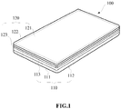
- FIG. 1 is a schematic diagram showing a connection state of the body 110 and the display screen module 120
- FIG. 2 is a schematic diagram showing a separation state of the body 110 and the display screen module 120.
- the body 110 includes a frame 111 and a back cover 112 connected with the frame 111.
- the frame 111 and the back cover 112 enclose an open cavity for installing the battery, the controller, function modules and other components of the display device 100.
- the display screen module 120 includes a display screen 121, and a glass cover 122 covering a display surface of the display screen 121.
- the display screen 121 is selected from an LCD (Liquid Crystal Display) screen, an OLED (Organic Light-Emitting Diode) screen, or an LED (Light Emitting Diode) screen.
- the display screen module 120 is installed on an open surface of the body 110 to block the cavity of the body 110.
- the display surface of the display screen module 120 is disposed facing the exterior of the cavity.
- the detachable connection between the body 110 and the display screen module 120 is implemented by the magnetic field.
- the body 110 further includes a first magnetic assembly 113 and the display screen module 120 further includes a second magnetic assembly 123.
- At least one of the first magnetic assembly and the second magnetic assembly is a magnetic-field controllable assembly.
- the magnetic-field controllable assembly may change its own magnetic field strength and magnetic pole direction (for example, to reverse the magnetic south pole and magnetic north pole).
- the first magnetic assembly 113 and the second magnetic assembly 123 can be connected with or separated from one another due to magnetic attraction or repulsion respectively.
- magnetic poles of the first magnetic assembly 113 are arranged to be opposite to magnetic poles of the second magnetic assembly 123. In this way, the attraction or repulsion effect of the first magnetic assembly 113 and the second magnetic assembly 123 is optimized.
- FIG.3 to FIG. 7 provide an implementation method of a magnetic-field controllable assembly 200.
- the magnetic-field controllable assembly 200 includes a ferromagnetic core 210 disposed around a set axis 300 (for example, the ferromagnetic core 210 has an annular structure).
- the set axis 300 is perpendicular to the display surface of the display screen module 120 when the body 110 and the display screen module 120 are connected.
- the magnetic-field controllable assembly 200 further includes a coil 220 wound around the ferromagnetic core 210.
- the coil 220 When the body 110 is connected with the display screen module 120, the coil 220 is surrounding the ferromagnetic core 210 with the set axis 300 as an axis.
- the coil 220 may be annularly attached to the ferromagnetic core 210.
- the coil 220 is disposed above and below the ferromagnetic core 210.
- the coil 220 is disposed on the inner and outer peripheral sides of the ferromagnetic core 210.
- the coil 220 may also be disposed in other ways, as long as it can ensure that the magnetic field excited by the coil 220 under the action of the current can realize the interaction between the first magnetic assembly 113 and the second magnetic assembly 123.
- the magnetic-field controllable assembly 200 further includes a charging module 230 electrically connected with the coil 220.
- the charging module 230 can provide the coil 220 with a first current I1 or a second current 12, wherein current directions of the first current I1 and the second current I2 are opposite.
- the coil 230 excites the first magnetic field, when the charging module 230 outputs the first current I1 to the coil 220.
- the ferromagnetic core 210 is magnetic when magnetized by the first magnetic field, and the magnetic pole distribution is the same as that of the first magnetic field. Taking the orientation shown in FIG. 6 as an example, the north (N) pole of the ferromagnetic core 210 is on the top and the south (S) pole of the ferromagnetic core is on the bottom. In combination with the orientation shown in FIG.
- the N pole of the ferromagnetic core 210 is at the display screen module 120 side, and the S pole is at the body 110 side.
- the coil 230 excites the second magnetic field, when the charging module 230 outputs the second current I2 for the coil 220.
- the ferromagnetic core 210 is magnetic when magnetized by the second magnetic field, and the magnetic pole distribution is the same as that of the second magnetic field.
- the current directions of the first current I1 and the second current I2 are opposite, thus the magnetic pole distributions of the first magnetic field and the second magnetic field are also opposite.
- the N pole of the ferromagnetic core 210 is on the bottom and the S pole of the ferromagnetic core is on the top.
- the S pole of the ferromagnetic core 210 is at the display screen module 120 side, and the N pole is at the body 110 side.
- the first current I1 or the second current I2 is provided to the coil 220 through the charging module 230 to change the magnetic pole distribution of the magnetic-field controllable assembly 200.
- the connection and separation between the first magnetic assembly 113 and the second magnetic assembly 123 can be realized by using the principle of opposite pole attraction and like pole repulsion.
- the detachable connection between the body 110 and the display screen module 120 is also implemented by this way.
- the way to realize the connection and separation through the action of a magnetic field ensures the structural integrity of the body 110 and the display screen module 120, prevents damage during the disassembly and installation process, and optimizes user experiences.
- a controller 130 electrically connected with the charging module 230 is also provided in the body 110.
- the controller 130 can control the charging module to output the first current I1 or the second current 12, in response to an operation triggering separation or triggering connection between the display screen module 120 and the body 110.
- the acquisition way includes, but is not limited to: acquisition by a triggering key (physical key or virtual key), acquisition by recognition of a voice command, acquisition by monitoring preset motion parameters (such as rotation angle, moving speed in specified direction, etc.).
- both of the first magnetic assembly 113 and the second magnetic assembly 123 are the magnetic-field controllable assembly 200.
- one of the first magnetic assembly 113 and the second magnetic assembly 123 is the magnetic-field controllable assembly 200, and another one is a permanent magnet.
- the first magnetic assembly 113 is the magnetic-field controllable assembly 200
- the second magnetic assembly 123 is a permanent magnet.
- the first magnetic assembly 113 is disposed on the inner wall of the frame 111 of the body 110.
- the first magnetic assembly 113 is the magnetic-field controllable assembly 200.
- the ferromagnetic core 210 and the coil 220 are disposed along an inner wall of the frame 111.
- the ferromagnetic core 210 and the coil 220 are attached to the inner wall of the frame 111.
- the charging module 230 of the first magnetic assembly 113 is disposed within the body 110, and connected with the coil 220 through pins or flexible circuit board(s).
- the second magnetic assembly 123 is disposed on one side of the display screen module 120 facing the body 110.
- the cover 122 of the display screen module 120 is disposed beyond the edge of the display screen 121.
- the second magnetic assembly 123 and the display screen 121 are located on the same side of the cover 122, and the second magnetic assembly 123 is disposed on a portion of the cover 122 beyond the display screen 121.
- the second magnetic assembly 123 is disposed on a back side of the display screen 121.
- the back side of the display screen 121 is a side opposite to the display surface of the display screen 121 (this scheme is not shown in FIG. 9 ).
- the second magnetic assembly 123 is a permanent magnet and disposed around the set axis 300.
- the set axis 300 is parallel with the separation direction of the display screen module 120 and the body 110.
- the second magnetic assembly 123 is an annular permanent magnet attached to the display screen module 120 (for example, as shown in FIG. 9 ), and the axis of the annular permanent magnet is parallel with the set axis 300.
- the second magnetic assembly 123 includes multiple permanent magnets (not shown in FIG. 9 ). The multiple permanent magnets are attached to the display screen module 120 in an annular manner, and the axis of the annulus formed by the multiple permanent magnets is parallel to the set axis 300.
- the ferromagnetic core 210 of the first magnetic assembly 113 is arranged to be opposite to the permanent magnet of the second magnetic assembly 123. In this way, the first magnetic assembly 113 is closely connected with the second magnetic assembly 123, when the body 110 is connected with the display screen module 120.
- an elastomeric seal 140 is provided within the body 110.
- the elastomeric seal 140 is disposed between attracted connection surfaces of the first magnetic assembly 113 and the second magnetic assembly 123 when the body 110 and the display screen module 140 are connected.
- the elastomeric seal 140 is an elastomeric sealing ring or an elastomeric sealing strip.
- the elastomeric seal 140 is made from foam, silicone, and other materials. The structural tightness of the body 110 and the display screen module 120 is improved by the elastomeric seal 140 to ensure the use security of the display device 100.
- the elastomeric seal 140 is disposed within the body 110 and covers one side of the first magnetic assembly 113 facing the display screen module 120 (for example, the first magnetic assembly 113 has an annular structure, and the elastomeric seal 140 covers an annular surface of the first magnetic assembly 113 facing the display screen module 120).
- the elastomeric seal 140 is disposed on the display screen module 120, and covers the permanent magnet of the second magnetic assembly 123.
- a motion sensor is provided within the body 110, which is configured to detect a motion parameter of the display device 100 along a vertical direction.
- the motion sensor is configured to detect the velocity and/or acceleration of the display device 100 along a vertical direction.
- the controller 130 is electrically connected with the motion sensor, and in response to that the motion parameter along the vertical direction, which is detected by the motion sensor, rises to a preset threshold, the controller is configured to control the charging module 230 to reduce an intensity of an output current.
- a preset threshold for example, the velocity and/or acceleration of the display device 100 rises to a preset threshold
- the magnetic field strength of the magnetic-field controllable assembly 200 is positively related to the strength of the current in the coil 220. Therefore, controlling the charging module 230 to reduce the strength of the output current can weaken the magnetism of the magnetic-field controllable assembly 200, which thus reduces the combination tightness of the first magnetic assembly 113 and the second magnetic assembly 123. It should be noted that the reduced current output by the charging module 230 satisfies the requirement that the magnetic field excited by the coil can still maintain the connection between the body 110 and the display screen module 120, then the structural security of the display device 100 can be ensured.
- the controller 130 controls the charging module 230 to reduce the strength of the output current, such that deformation of the elastomeric seal 140, which is resulted from the press by the first magnetic assembly 113 and the second magnetic assembly 123, reduces. Further, when the display device 100 decelerates or touches the ground, the elastomeric seal 140 can be further compressed to play a buffering role and realize the anti-falling effect, which can ensure the structural integrity of the display screen module 120.
- the display device 100 further includes a movable connecting arm 150, wherein one end of the movable connecting arm 150 is disposed within the body 110, and the other end of the movable connecting arm 150 is connected with the display screen module 120.
- the movable connecting arm 150 is telescopic relative to the body 110, for example, the movable connection arm 150 is a telescopic movable connection arm.
- the controller 130 of the display device 100 is electrically connected with the movable connecting arm 150, and the controller 130 is configured to control the movable connecting arm 150 to drive the display screen module 120 to eject from the body 110, in response to an operation triggering separation between the display screen module 120 and the body 110.
- the controller 130 preferentially controls the charging module 230 of the magnetic-field controllable assembly 200, and then actuates the movable connecting arm 150, after the first magnetic assembly 113 mutually magnetically repels with the second magnetic assembly 123.
- the controller 130 can control the movable connecting arm 150 to drive the display screen module 120 to retract to the body 110, in response to the operation triggering connection between the display screen module 120 and the body 110.
- the controller 130 preferentially controls the charging module 230 of the magnetic-field controllable assembly 200, and then actuates the movable connecting arm 150, after the first magnetic assembly 113 mutually magnetically attracts with the second magnetic assembly 123.
- the display device 100 is provided with a movable connecting arm 150, which is connected with one side of the display screen module 120 facing the interior of the body 110.
- the display device 100 is provided with at least two movable connecting arms 150, and the joints of the movable connecting arms 150 and the display screen module 120 are evenly distributed on one side of the display screen module 120 facing the interior of the body 110. In this way, it is ensured that the movable connecting arm 150 acts stably on the display screen module 120.
- the display device 100 when the display device 100 is in use, it is difficult for the display device 100 to maintain stable due to the influence from external environment. For example, the display device 100 frequently shakes during use due to the influence of the vehicle speed and road conditions when the user is traveling on a train, car, or other means of transportation, which results in visual fatigue and even dizziness for the user, thus affecting user experiences.
- the display device 100 includes a motion sensor to detect a motion parameter of the body 110.
- the body has six degrees of freedom of motion during use. As shown in FIG. 13 , the six degrees of freedom of motion of the body 110 include the degrees of freedom of translation along the positive and negative directions of the x-axis, y-axis, and z-axis, as well as the degrees of freedom of rotation around the x-axis, y-axis, and z-axis as axes.
- the x-axis, y-axis, and z-axis use the display device 100 as a reference body
- the plane formed by the x-axis and the y-axis is the surface on which the display surface of the display screen module 120 locates
- the z-axis is perpendicular to the display surface of the display screen module 120.
- the x-axis, y-axis, and z-axis use the ground as a reference body
- the plane formed by the x-axis and the y-axis is the horizontal plane
- the z-axis is distributed in the vertical direction.
- the body 110 can move freely in space under external forces.
- the motion sensor is configured to detect the motion parameter of the body 110 in each of six degrees of freedom of motion.
- the motion parameters include, but are not limited to, the velocity, acceleration, or rotation angle of the body 110.
- the controller is electrically connected with the charging module, and when the display screen module 120 is magnetically separated from the body 110 due to magnetic repulsion, the controller 130 receives the motion parameters detected by the motion sensor. In addition, the controller 130 determines the current motion state of the body 110 according to the motion parameters of the body 110 received by the motion sensor. For example, when the motion amplitude and a motion frequency of the body 100 are within respective preset threshold ranges, the controller 130 determines that the body 110 is currently in a shaking state.
- the end of the movable connecting arm disposed within the body has six degrees of freedom of motion.
- the controller 130 determines that the motion amplitude and motion frequency of the body 110 are within respective preset threshold ranges, the controller 130 controls, according to the motion parameters of the body 110 that are obtained by the motion sensor, the movable connecting arm 150 to drive the display screen module 120 to move backwards relative to the body 110.
- the display screen module 120 is always located in a preset region. And in this preset region, the display screen module 120 remains stable relative to the user.
- the maximum shaking amplitude of the display screen module 120 within the preset region is less than or equal to 5 mm. Accordingly, the movable connecting arm 150 is used to prevent the display screen module 120 from being affected by the movement of the body 110. In this case, when the display device 100 is used, the display screen module 120 is always in a relatively stable state for the user. Its vibration amplitude is very small or even hard to detect by the human eye, which optimizes the user experience and plays an anti-shaking effect.
- the display screen module 120 is provided with an independent power supply assembly, and the display screen module 120 is communicatively connected with the controller 130 within the body 110. Accordingly, the display screen module 120 receives power from the independent power supply assembly after the display screen module 120 is separated from the body 110, and the display screen module 120 receives a display instruction sent by the controller 130. In this way, an image can still be displayed, after the display screen module 120 is separated from the body 110.
- the movable connecting arm 150 may optionally adopt an anti-shaking head mechanism. It should also be noted that, in this embodiment, the display device 100 preferably uses only one movable connecting arm 150 to maintain the stability of the display screen module 120 in six degrees of freedom of motion.
- the display screen module further includes a data transmission module 124 and a first power module 125.
- the data transmission module 124 is communicatively connected with the controller 130 within the body 110.
- the data transmission module 124 is wirelessly connected to the communication module in the controller 130, where the method for wireless connection includes, but is not limited to, Bluetooth, WIFI (Wireless Fidelity, wireless local area network based on IEEE 802.11b), and ZigBee wireless transmission technology.
- the data transmission module 124 and the display screen module 12 adopt a data connection, for example, the data transmission module 124 is connected to the control chip of the display screen module 120 through a cable or a flexible circuit board.
- the first power module 125 is connected with the display screen module 120 and the data transmission module 124, so as to supply power to the display screen module 120 and the data transmission module 124.
- the display screen module 120 when the display screen module 120 is separated from the body 110, the display information sent by the controller 130 is sent to the control chip of the display screen module 120 through the data transmission module 124, the display screen module 120 can thus display a preset image corresponding to the display information. In this way, the display screen module 120 can be used normally, even separated from the body 110. With the display device 100, the independent use of the display screen module 120 can be realized. Furthermore, compared with the whole display device 100, the display screen module 120 is thinner and narrower, so that its user will have excellent grip feel and optimized user experiences.
- the body 110 also includes a second power module 114 module that mates with the first power module 125 to charge the first power module 125.
- the first power module 125 and the second power module 114 are connected through contacts.
- the contacts of the first power module 125 and the contacts of the second power module 114 abuts against each other to implement charging.
- the first power module 125 and the second power module 114 are wirelessly charged.
- the first power module 125 includes a first charging coil
- the second power module 114 includes a second charging coil.
- the first charging coil mates with the second charging coil to implement charging.
- the battery capacity information is shown on the display surface of the display screen module 120.
- the display screen module 120 displays a connection prompt.
- the display device 100 has a detachable body 110 and a display screen module 120, which are convenient for disassembly and maintenance, and for replacement of components. Furthermore, based on the characteristics of detachable connection between the body 110 and the display screen module 120, the anti-shaking effect is achieved by the movable connecting arm 150; and the independent use of the display screen module 120 can be achieved with the configuration of the data transmission module 124, the first power module 125 and the second power module 114, thereby optimizing user experiences.
Landscapes
- Engineering & Computer Science (AREA)
- Theoretical Computer Science (AREA)
- Computer Hardware Design (AREA)
- General Engineering & Computer Science (AREA)
- Physics & Mathematics (AREA)
- Human Computer Interaction (AREA)
- General Physics & Mathematics (AREA)
- Signal Processing (AREA)
- Power Engineering (AREA)
- Electromagnetism (AREA)
- Devices For Indicating Variable Information By Combining Individual Elements (AREA)
- Computer Networks & Wireless Communication (AREA)
- Mechanical Engineering (AREA)
- Charge And Discharge Circuits For Batteries Or The Like (AREA)
Abstract
Description
- The present disclosure relates to the field of display device, and more particularly, to a display device.
- Display devices, such as mobile phones, tablets and iPads, are widely used in people's work and life. A display screen module for displaying images is an indispensable part of a display device. However, display screen modules in display devices provided in existing techniques are difficult to be disassembled, which affects user experiences.
- Embodiments of the present disclosure provide a display device so as to solve the problems in existing techniques.
- The display device provided by the embodiments of the present disclosure includes: a body, and a display screen module detachably connected with the body,
wherein the body includes a first magnetic assembly; and
the display screen module includes a second magnetic assembly,
wherein at least one of the first magnetic assembly and the second magnetic assembly is a magnetic-field controllable assembly, and the first magnetic assembly and the second magnetic assembly are connected with or separated from one another due to magnetic attraction or repulsion respectively. - The connection between the body and the display screen module is implemented through the attraction between opposite magnetic fields of the first magnetic assembly and the second magnetic assembly; furthermore, the separation between the body and the display screen module is implemented through the repulsion between like magnetic fields of the first magnetic assembly and the second magnetic assembly. The display device provided by the embodiments of the present disclosure has detachably connected body and display screen module, thus the display screen module is convenient for disassembly and installation while assuring the structural integrity of the body and the display screen module, thereby optimizing user experiences.
- According to an embodiment of the disclosure, magnetic poles of the first magnetic assembly may be arranged to be opposite to magnetic poles of the second magnetic assembly.
- According to an embodiment of the disclosure, the magnetic-field controllable assembly may include:
- a ferromagnetic core disposed around a set axis, the set axis being perpendicular to a display surface of the display screen module when the body and the display screen module are connected;
- a coil annularly attached to the ferromagnetic core with the set axis as an axis; and
- a charging module, electrically connected with the coil, configured to provide the coil with a first current or a second current, wherein current directions of the first current and the second current are opposite.
- According to an embodiment of the disclosure, a controller may be provided within the body, the controller being electrically connected with the charging module, wherein the controller is configured to control the charging module to output the first current or the second current.
- According to an embodiment of the disclosure, the first magnetic assembly may be the magnetic-field controllable assembly, and the second magnetic assembly may include a permanent magnet.
- According to an embodiment of the disclosure, the body may include a frame, the ferromagnetic core and the coil being disposed along an inner wall of the frame.
- According to an embodiment of the disclosure, the permanent magnet may be disposed on a side of the display screen module facing the body, and the permanent magnet is disposed around the set axis.
- According to an embodiment of the disclosure, an elastomeric seal may be provided within the body, the elastomeric seal being located between attracted connection surfaces of the first magnetic assembly and the second magnetic assembly when the body and the display screen module are connected.
- According to an embodiment of the disclosure, a motion sensor may be provided within the body, the motion sensor being configured to detect a motion parameter of the display device along a vertical direction.
- According to an embodiment of the disclosure, the controller may be electrically connected with the motion sensor, and in response to that the motion parameter along the vertical direction, which is detected by the motion sensor, rises to a preset threshold, the controller may be configured to control the charging module to reduce an intensity of an output current of the charging module, wherein the reduced intensity of the output current is sufficient to ensure the connection between the body and the display screen module.
- According to an embodiment of the disclosure, the display device may further include a movable connecting arm, wherein one end of the movable connecting arm is disposed within the body, and the other end of the movable connecting arm is connected with the display screen module.
- According to an embodiment of the disclosure, the controller may be electrically connected with the movable connecting arm, and the controller may be configured to control the movable connecting arm to drive the display screen module to eject from the body, in response to an operation triggering separation between the display screen module and the body;
the controller may be further configured to control the movable connecting arm to drive the display screen module to retract to the body, in response to an operation triggering connection between the display screen module and the body. - According to an embodiment of the disclosure, the display device may further include a motion sensor configured to detect a motion parameter of the body,
wherein the controller is electrically connected with the motion sensor, and when the display screen module mutually repels with the body, the controller is configured to, in response to a motion amplitude and a motion frequency of the body being within respective preset threshold ranges, control, according to the motion parameter detected by the motion sensor, the movable connecting arm to drive the display screen module to move backwards relative to the body, such that the display screen module is disposed within a preset region. - According to an embodiment of the disclosure, the motion sensor may be configured to detect the motion parameter of the body in each of six degrees of freedom of motion; with the end of the movable connecting arm connected with the display screen module as a reference, the end of the movable connecting arm disposed within the body has six degrees of freedom of motion.
- According to an embodiment of the disclosure, the display screen module may further include:
- a data transmission module, communicatively connected with the controller, configured to receive display information sent by the controller to control the display screen module to display a preset image; and
- a first power module, configured to supply power for the display screen module and the data transmission module.
- According to an embodiment of the disclosure, the body may further include a second power module configured to charge the first power module.
- According to an embodiment of the disclosure, the first power module may mate with the second power module through wireless charging.
- The display device provided by the embodiments of the present disclosure has at least beneficial effects as follows.
-
-
FIG. 1 andFIG. 2 are schematic diagrams showing working states of a display device according to different exemplary embodiments. -
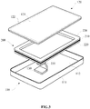
FIG. 3 is a schematic diagram showing relative positions of a magnetic-field controllable assembly, a display screen module and a body of a display device according to one exemplary embodiment. -
FIG. 4 andFIG. 5 are schematic structural diagrams of a magnetic-field controllable assembly of a display device according to different exemplary embodiments. -
FIG. 6 andFIG. 7 are the working principle diagrams of a magnetic-field controllable assembly of a display device according to different exemplary embodiments. -
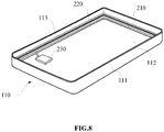
FIG. 8 is a schematic structural diagram of a body of a display device according to one exemplary embodiment. -
FIG. 9 is a schematic structural diagram of a display screen module of a display device, according to one exemplary embodiment. -
FIG. 10 andFIG. 11 are schematic diagrams showing setting modes of an elastomeric seal of a display device according to different exemplary embodiments. -
FIG. 12 is a schematic structural diagram of a display device according to another exemplary embodiment. -
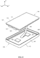
FIG. 13 is a schematic structural diagram of a display device according to another exemplary embodiment. - Reference will now be made in detail to exemplary embodiments, examples of which are illustrated in the accompanying drawings. The following description refers to the accompanying drawings in which the same numbers in different drawings represent the same or similar elements unless otherwise represented. The implementations set forth in the following description of exemplary embodiments do not represent all implementations consistent with the invention. Instead, they are merely examples of apparatuses and methods consistent with aspects related to the invention as recited in the appended claims.
- The terminology used in this disclosure is for the purpose of describing particular embodiments only and is not intended to limit the disclosure. The technical or scientific terms used in this disclosure shall have the general meanings understood by those with general skills in the field to which this disclosure belongs, unless otherwise defined. The words of "first", "second", and the like used in this disclosure and the claims do not indicate any order, quantity, or importance, but are only used to distinguish different components. Similarly, the words of "a" or "one", and the like do not refer to quantitative restrictions, but to mean there is at least one. Unless otherwise specified, the words of "comprise" or "comprising" and the like mean that the components or objects appearing before the words "comprise" or "comprising" cover the components or objects appearing after the words "comprise" or "comprising" and their equivalents, and other components or objects are not excluded. And the words of "connected" or "connecting" and the like are not limited to physical or mechanical connections, and may include electrical connections, whether direct or indirect.
- The singular forms such as "a", "the" and "this" used in the description and the appended claims are also intended to include the plural forms, unless the context clearly indicates other meanings. It should be also understood that the term "and/or" used herein refers to and includes any or all possible combinations of one or more associated listed items.
- In some embodiments, the display screen module of the display device is fixedly connected with the body of the display device, in this way, during replacement of the display screen module, the connection between the display screen module and the body will be damaged, which not only increases the cost of screen replacement for the display device, but also leads to poor user experiences.
- Based on the foregoing, the display device is provided by the embodiments of the present disclosure.
FIG. 1 to FIG. 13 are schematic structural diagrams of a display device according to different exemplary embodiments. It should be noted that the figures only use a mobile phone as an example for illustration, but in the embodiments of the present disclosure, the display device includes, but is not limited to, a mobile phone, a tablet computer, a wearable device (such as a smart watch, a bracelet), an on-board device, or a medical device. - As shown in
FIG. 1 andFIG. 2 , thedisplay device 100 includes abody 110, and adisplay screen module 120 detachably connected with thebody 110. The words "detachably connected" means that thedisplay screen module 120 and thebody 110 can be detached and connected without damaging their structures. Wherein,FIG. 1 is a schematic diagram showing a connection state of thebody 110 and thedisplay screen module 120,FIG. 2 is a schematic diagram showing a separation state of thebody 110 and thedisplay screen module 120. - The
body 110 includes aframe 111 and aback cover 112 connected with theframe 111. Theframe 111 and theback cover 112 enclose an open cavity for installing the battery, the controller, function modules and other components of thedisplay device 100. - The
display screen module 120 includes adisplay screen 121, and aglass cover 122 covering a display surface of thedisplay screen 121. Thedisplay screen 121 is selected from an LCD (Liquid Crystal Display) screen, an OLED (Organic Light-Emitting Diode) screen, or an LED (Light Emitting Diode) screen. And thedisplay screen module 120 is installed on an open surface of thebody 110 to block the cavity of thebody 110. The display surface of thedisplay screen module 120 is disposed facing the exterior of the cavity. - In an embodiment, the detachable connection between the
body 110 and thedisplay screen module 120 is implemented by the magnetic field. Specifically, thebody 110 further includes a firstmagnetic assembly 113 and thedisplay screen module 120 further includes a secondmagnetic assembly 123. At least one of the first magnetic assembly and the second magnetic assembly is a magnetic-field controllable assembly. The magnetic-field controllable assembly may change its own magnetic field strength and magnetic pole direction (for example, to reverse the magnetic south pole and magnetic north pole). With the magnetic-field controllable assembly, the firstmagnetic assembly 113 and the secondmagnetic assembly 123 can be connected with or separated from one another due to magnetic attraction or repulsion respectively. - According to an embodiment of the disclosure, magnetic poles of the first
magnetic assembly 113 are arranged to be opposite to magnetic poles of the secondmagnetic assembly 123. In this way, the attraction or repulsion effect of the firstmagnetic assembly 113 and the secondmagnetic assembly 123 is optimized. - In the embodiments of the present disclosure,
FIG.3 to FIG. 7 provide an implementation method of a magnetic-fieldcontrollable assembly 200. As shown inFIG. 3 and combined withFIG. 2 , the magnetic-fieldcontrollable assembly 200 includes aferromagnetic core 210 disposed around a set axis 300 (for example, theferromagnetic core 210 has an annular structure). Moreover, theset axis 300 is perpendicular to the display surface of thedisplay screen module 120 when thebody 110 and thedisplay screen module 120 are connected. - The magnetic-field
controllable assembly 200 further includes acoil 220 wound around theferromagnetic core 210. When thebody 110 is connected with thedisplay screen module 120, thecoil 220 is surrounding theferromagnetic core 210 with theset axis 300 as an axis. According to an embodiment of the disclosure, thecoil 220 may be annularly attached to theferromagnetic core 210. - For example, as shown in
FIG. 4 , thecoil 220 is disposed above and below theferromagnetic core 210. - For example, as shown in
FIG. 4 , thecoil 220 is disposed on the inner and outer peripheral sides of theferromagnetic core 210. - Of course, the
coil 220 may also be disposed in other ways, as long as it can ensure that the magnetic field excited by thecoil 220 under the action of the current can realize the interaction between the firstmagnetic assembly 113 and the secondmagnetic assembly 123. - The magnetic-field
controllable assembly 200 further includes acharging module 230 electrically connected with thecoil 220. Thecharging module 230 can provide thecoil 220 with a first current I1 or a second current 12, wherein current directions of the first current I1 and the second current I2 are opposite. - As shown in
FIG. 6 , thecoil 230 excites the first magnetic field, when thecharging module 230 outputs the first current I1 to thecoil 220. And theferromagnetic core 210 is magnetic when magnetized by the first magnetic field, and the magnetic pole distribution is the same as that of the first magnetic field. Taking the orientation shown inFIG. 6 as an example, the north (N) pole of theferromagnetic core 210 is on the top and the south (S) pole of the ferromagnetic core is on the bottom. In combination with the orientation shown inFIG. 3 , since the axial direction of theferromagnetic core 210 and thecoil 220 coincides with the separation direction of thedisplay screen module 120 and thebody 110, the N pole of theferromagnetic core 210 is at thedisplay screen module 120 side, and the S pole is at thebody 110 side. - As shown in
FIG. 7 , thecoil 230 excites the second magnetic field, when thecharging module 230 outputs the second current I2 for thecoil 220. And theferromagnetic core 210 is magnetic when magnetized by the second magnetic field, and the magnetic pole distribution is the same as that of the second magnetic field. However, the current directions of the first current I1 and the second current I2 are opposite, thus the magnetic pole distributions of the first magnetic field and the second magnetic field are also opposite. Taking the orientation shown inFIG. 7 as an example, herein, the N pole of theferromagnetic core 210 is on the bottom and the S pole of the ferromagnetic core is on the top. In combination with the orientation shown inFIG. 3 , the S pole of theferromagnetic core 210 is at thedisplay screen module 120 side, and the N pole is at thebody 110 side. - The first current I1 or the second current I2 is provided to the
coil 220 through thecharging module 230 to change the magnetic pole distribution of the magnetic-fieldcontrollable assembly 200. In this way, the connection and separation between the firstmagnetic assembly 113 and the secondmagnetic assembly 123 can be realized by using the principle of opposite pole attraction and like pole repulsion. Further, the detachable connection between thebody 110 and thedisplay screen module 120 is also implemented by this way. Furthermore, the way to realize the connection and separation through the action of a magnetic field, ensures the structural integrity of thebody 110 and thedisplay screen module 120, prevents damage during the disassembly and installation process, and optimizes user experiences. - Referring to
FIG. 3 , acontroller 130 electrically connected with thecharging module 230 is also provided in thebody 110. Thecontroller 130 can control the charging module to output the first current I1 or the second current 12, in response to an operation triggering separation or triggering connection between thedisplay screen module 120 and thebody 110. - In the embodiments of the present disclosure, there is no specific limitation on the way for acquisition of the operation triggering separation or triggering connection between the
display screen module 120 and thebody 110, herein the acquisition way includes, but is not limited to: acquisition by a triggering key (physical key or virtual key), acquisition by recognition of a voice command, acquisition by monitoring preset motion parameters (such as rotation angle, moving speed in specified direction, etc.). - With regard to the implementation of the first
magnetic assembly 113 and the secondmagnetic assembly 123, according to an embodiment, both of the firstmagnetic assembly 113 and the secondmagnetic assembly 123 are the magnetic-fieldcontrollable assembly 200. According to an embodiment, one of the firstmagnetic assembly 113 and the secondmagnetic assembly 123 is the magnetic-fieldcontrollable assembly 200, and another one is a permanent magnet. - In the embodiments of the present disclosure, the first
magnetic assembly 113 is the magnetic-fieldcontrollable assembly 200, and the secondmagnetic assembly 123 is a permanent magnet. In this way, on the premise of realizing the detachable connection between thebody 110 and thedisplay screen module 120, the production difficulty and cost of theoverall display device 100 are reduced due to the characteristics of simple structure and easy installation of the permanent magnet. Particularly, the use of permanent magnet reduces the structural complexity of thedisplay screen module 120, such that thedisplay screen module 120 is easy to package and thus the appearance of thedisplay screen module 120 is beautified. - As shown in
FIG. 8 , the firstmagnetic assembly 113 is disposed on the inner wall of theframe 111 of thebody 110. The firstmagnetic assembly 113 is the magnetic-fieldcontrollable assembly 200. Herein, theferromagnetic core 210 and thecoil 220 are disposed along an inner wall of theframe 111. For example, theferromagnetic core 210 and thecoil 220 are attached to the inner wall of theframe 111. Moreover, thecharging module 230 of the firstmagnetic assembly 113 is disposed within thebody 110, and connected with thecoil 220 through pins or flexible circuit board(s). - As shown in
FIG. 9 and combined withFIG. 2 , the secondmagnetic assembly 123 is disposed on one side of thedisplay screen module 120 facing thebody 110. - According to an embodiment of the disclosure, as shown in
FIG. 9 , thecover 122 of thedisplay screen module 120 is disposed beyond the edge of thedisplay screen 121. The secondmagnetic assembly 123 and thedisplay screen 121 are located on the same side of thecover 122, and the secondmagnetic assembly 123 is disposed on a portion of thecover 122 beyond thedisplay screen 121. - According to an embodiment of the disclosure, the second
magnetic assembly 123 is disposed on a back side of thedisplay screen 121. The back side of thedisplay screen 121 is a side opposite to the display surface of the display screen 121 (this scheme is not shown inFIG. 9 ). - The second
magnetic assembly 123 is a permanent magnet and disposed around theset axis 300. Theset axis 300 is parallel with the separation direction of thedisplay screen module 120 and thebody 110. - Exemplarily, the second
magnetic assembly 123 is an annular permanent magnet attached to the display screen module 120 (for example, as shown inFIG. 9 ), and the axis of the annular permanent magnet is parallel with theset axis 300. For example, the secondmagnetic assembly 123 includes multiple permanent magnets (not shown inFIG. 9 ). The multiple permanent magnets are attached to thedisplay screen module 120 in an annular manner, and the axis of the annulus formed by the multiple permanent magnets is parallel to theset axis 300. - In an embodiment, the
ferromagnetic core 210 of the firstmagnetic assembly 113 is arranged to be opposite to the permanent magnet of the secondmagnetic assembly 123. In this way, the firstmagnetic assembly 113 is closely connected with the secondmagnetic assembly 123, when thebody 110 is connected with thedisplay screen module 120. - Further, as shown in
FIGS. 10 and11 , anelastomeric seal 140 is provided within thebody 110. Theelastomeric seal 140 is disposed between attracted connection surfaces of the firstmagnetic assembly 113 and the secondmagnetic assembly 123 when thebody 110 and thedisplay screen module 140 are connected. Wherein, theelastomeric seal 140 is an elastomeric sealing ring or an elastomeric sealing strip. According to an embodiment of the disclosure, theelastomeric seal 140 is made from foam, silicone, and other materials. The structural tightness of thebody 110 and thedisplay screen module 120 is improved by theelastomeric seal 140 to ensure the use security of thedisplay device 100. - And, According to an embodiment of the disclosure, as shown in
FIG. 10 , theelastomeric seal 140 is disposed within thebody 110 and covers one side of the firstmagnetic assembly 113 facing the display screen module 120 (for example, the firstmagnetic assembly 113 has an annular structure, and theelastomeric seal 140 covers an annular surface of the firstmagnetic assembly 113 facing the display screen module 120). According to an embodiment of the disclosure, as shown inFIG. 11 , theelastomeric seal 140 is disposed on thedisplay screen module 120, and covers the permanent magnet of the secondmagnetic assembly 123. - In an embodiment, a motion sensor is provided within the
body 110, which is configured to detect a motion parameter of thedisplay device 100 along a vertical direction. For example, the motion sensor is configured to detect the velocity and/or acceleration of thedisplay device 100 along a vertical direction. Moreover, thecontroller 130 is electrically connected with the motion sensor, and in response to that the motion parameter along the vertical direction, which is detected by the motion sensor, rises to a preset threshold, the controller is configured to control thecharging module 230 to reduce an intensity of an output current. - When the motion parameter along the vertical direction, which is detected by the motion sensor, rises to a preset threshold (for example, the velocity and/or acceleration of the
display device 100 rises to a preset threshold), it indicates that thedisplay device 100 is in a falling state. - In addition, the magnetic field strength of the magnetic-field
controllable assembly 200 is positively related to the strength of the current in thecoil 220. Therefore, controlling thecharging module 230 to reduce the strength of the output current can weaken the magnetism of the magnetic-fieldcontrollable assembly 200, which thus reduces the combination tightness of the firstmagnetic assembly 113 and the secondmagnetic assembly 123. It should be noted that the reduced current output by thecharging module 230 satisfies the requirement that the magnetic field excited by the coil can still maintain the connection between thebody 110 and thedisplay screen module 120, then the structural security of thedisplay device 100 can be ensured. - In this case, when the
display device 100 falls, thecontroller 130 controls thecharging module 230 to reduce the strength of the output current, such that deformation of theelastomeric seal 140, which is resulted from the press by the firstmagnetic assembly 113 and the secondmagnetic assembly 123, reduces. Further, when thedisplay device 100 decelerates or touches the ground, theelastomeric seal 140 can be further compressed to play a buffering role and realize the anti-falling effect, which can ensure the structural integrity of thedisplay screen module 120. - In an embodiment, as shown in
FIG. 12 , thedisplay device 100 further includes a movable connectingarm 150, wherein one end of the movable connectingarm 150 is disposed within thebody 110, and the other end of the movable connectingarm 150 is connected with thedisplay screen module 120. The movable connectingarm 150 is telescopic relative to thebody 110, for example, themovable connection arm 150 is a telescopic movable connection arm. - The
controller 130 of thedisplay device 100 is electrically connected with the movable connectingarm 150, and thecontroller 130 is configured to control the movable connectingarm 150 to drive thedisplay screen module 120 to eject from thebody 110, in response to an operation triggering separation between thedisplay screen module 120 and thebody 110. As a preferred solution, thecontroller 130 preferentially controls thecharging module 230 of the magnetic-fieldcontrollable assembly 200, and then actuates the movable connectingarm 150, after the firstmagnetic assembly 113 mutually magnetically repels with the secondmagnetic assembly 123. - The
controller 130 can control the movable connectingarm 150 to drive thedisplay screen module 120 to retract to thebody 110, in response to the operation triggering connection between thedisplay screen module 120 and thebody 110. As a preferred solution, thecontroller 130 preferentially controls thecharging module 230 of the magnetic-fieldcontrollable assembly 200, and then actuates the movable connectingarm 150, after the firstmagnetic assembly 113 mutually magnetically attracts with the secondmagnetic assembly 123. - According to an embodiment of the disclosure, the
display device 100 is provided with a movable connectingarm 150, which is connected with one side of thedisplay screen module 120 facing the interior of thebody 110. According to an embodiment of the disclosure, thedisplay device 100 is provided with at least two movable connectingarms 150, and the joints of the movable connectingarms 150 and thedisplay screen module 120 are evenly distributed on one side of thedisplay screen module 120 facing the interior of thebody 110. In this way, it is ensured that the movable connectingarm 150 acts stably on thedisplay screen module 120. - In some embodiments, when the
display device 100 is in use, it is difficult for thedisplay device 100 to maintain stable due to the influence from external environment. For example, thedisplay device 100 frequently shakes during use due to the influence of the vehicle speed and road conditions when the user is traveling on a train, car, or other means of transportation, which results in visual fatigue and even dizziness for the user, thus affecting user experiences. - In view of the above problems, the embodiments of the present disclosure provide the following solutions. In an embodiment, the
display device 100 includes a motion sensor to detect a motion parameter of thebody 110. - The body has six degrees of freedom of motion during use. As shown in
FIG. 13 , the six degrees of freedom of motion of thebody 110 include the degrees of freedom of translation along the positive and negative directions of the x-axis, y-axis, and z-axis, as well as the degrees of freedom of rotation around the x-axis, y-axis, and z-axis as axes. - Herein, according to an embodiment of the disclosure, the x-axis, y-axis, and z-axis use the
display device 100 as a reference body, the plane formed by the x-axis and the y-axis is the surface on which the display surface of thedisplay screen module 120 locates, and the z-axis is perpendicular to the display surface of thedisplay screen module 120. According to an embodiment of the disclosure, the x-axis, y-axis, and z-axis use the ground as a reference body, the plane formed by the x-axis and the y-axis is the horizontal plane, and the z-axis is distributed in the vertical direction. In this case, thebody 110 can move freely in space under external forces. - According to an embodiment of the disclosure, the motion sensor is configured to detect the motion parameter of the
body 110 in each of six degrees of freedom of motion. The motion parameters include, but are not limited to, the velocity, acceleration, or rotation angle of thebody 110. - In the
display device 100, the controller is electrically connected with the charging module, and when thedisplay screen module 120 is magnetically separated from thebody 110 due to magnetic repulsion, thecontroller 130 receives the motion parameters detected by the motion sensor. In addition, thecontroller 130 determines the current motion state of thebody 110 according to the motion parameters of thebody 110 received by the motion sensor. For example, when the motion amplitude and a motion frequency of thebody 100 are within respective preset threshold ranges, thecontroller 130 determines that thebody 110 is currently in a shaking state. - Moreover, in the embodiments of the present disclosure, with the end of the movable connecting arm connected with the display screen module as a reference, the end of the movable connecting arm disposed within the body has six degrees of freedom of motion. In this case, when the
controller 130 determines that the motion amplitude and motion frequency of thebody 110 are within respective preset threshold ranges, thecontroller 130 controls, according to the motion parameters of thebody 110 that are obtained by the motion sensor, the movable connectingarm 150 to drive thedisplay screen module 120 to move backwards relative to thebody 110. - In this way, the
display screen module 120 is always located in a preset region. And in this preset region, thedisplay screen module 120 remains stable relative to the user. - As a preferred solution, the maximum shaking amplitude of the
display screen module 120 within the preset region is less than or equal to 5 mm. Accordingly, the movable connectingarm 150 is used to prevent thedisplay screen module 120 from being affected by the movement of thebody 110. In this case, when thedisplay device 100 is used, thedisplay screen module 120 is always in a relatively stable state for the user. Its vibration amplitude is very small or even hard to detect by the human eye, which optimizes the user experience and plays an anti-shaking effect. - In addition, the
display screen module 120 is provided with an independent power supply assembly, and thedisplay screen module 120 is communicatively connected with thecontroller 130 within thebody 110. Accordingly, thedisplay screen module 120 receives power from the independent power supply assembly after thedisplay screen module 120 is separated from thebody 110, and thedisplay screen module 120 receives a display instruction sent by thecontroller 130. In this way, an image can still be displayed, after thedisplay screen module 120 is separated from thebody 110. - Herein, the movable connecting
arm 150 may optionally adopt an anti-shaking head mechanism. It should also be noted that, in this embodiment, thedisplay device 100 preferably uses only one movable connectingarm 150 to maintain the stability of thedisplay screen module 120 in six degrees of freedom of motion. - In an embodiment, as shown in
FIG. 13 , the display screen module further includes adata transmission module 124 and afirst power module 125. - Herein, the
data transmission module 124 is communicatively connected with thecontroller 130 within thebody 110. For example, thedata transmission module 124 is wirelessly connected to the communication module in thecontroller 130, where the method for wireless connection includes, but is not limited to, Bluetooth, WIFI (Wireless Fidelity, wireless local area network based on IEEE 802.11b), and ZigBee wireless transmission technology. Moreover, thedata transmission module 124 and thedisplay screen module 12 adopt a data connection, for example, thedata transmission module 124 is connected to the control chip of thedisplay screen module 120 through a cable or a flexible circuit board. - The
first power module 125 is connected with thedisplay screen module 120 and thedata transmission module 124, so as to supply power to thedisplay screen module 120 and thedata transmission module 124. - In this case, when the
display screen module 120 is separated from thebody 110, the display information sent by thecontroller 130 is sent to the control chip of thedisplay screen module 120 through thedata transmission module 124, thedisplay screen module 120 can thus display a preset image corresponding to the display information. In this way, thedisplay screen module 120 can be used normally, even separated from thebody 110. With thedisplay device 100, the independent use of thedisplay screen module 120 can be realized. Furthermore, compared with thewhole display device 100, thedisplay screen module 120 is thinner and narrower, so that its user will have excellent grip feel and optimized user experiences. - Further, the
body 110 also includes asecond power module 114 module that mates with thefirst power module 125 to charge thefirst power module 125. - Exemplarily, the
first power module 125 and thesecond power module 114 are connected through contacts. When thedisplay screen module 120 is connected with thebody 110, the contacts of thefirst power module 125 and the contacts of thesecond power module 114 abuts against each other to implement charging. - Exemplarily, the
first power module 125 and thesecond power module 114 are wirelessly charged. For instance, thefirst power module 125 includes a first charging coil, and thesecond power module 114 includes a second charging coil. When thedisplay screen module 120 is aligned with the open surface of the cavity of thebody 110 and the distance between thedisplay screen module 120 and thebody 110 does not exceed a preset threshold, the first charging coil mates with the second charging coil to implement charging. - In addition, according to an embodiment of the disclosure, the battery capacity information is shown on the display surface of the
display screen module 120. When thedisplay screen module 120 is separated from thebody 110 and the battery capacity of thefirst power module 125 is lower than a preset threshold, thedisplay screen module 120 displays a connection prompt. - The
display device 100 provided by the embodiments of the present disclosure has adetachable body 110 and adisplay screen module 120, which are convenient for disassembly and maintenance, and for replacement of components. Furthermore, based on the characteristics of detachable connection between thebody 110 and thedisplay screen module 120, the anti-shaking effect is achieved by the movable connectingarm 150; and the independent use of thedisplay screen module 120 can be achieved with the configuration of thedata transmission module 124, thefirst power module 125 and thesecond power module 114, thereby optimizing user experiences. - The above are merely preferred embodiments of the present disclosure, and are not intended to limit the present disclosure. Any modification, equivalent replacement, or improvement made within the spirit and principles of the present disclosure shall be included in the scope of protection of this disclosure.
Claims (15)
- A display device (100), comprising: a body (110), and a display screen module (120) detachably connected with the body (110),
wherein the body (110) comprises a first magnetic assembly (113); and
the display screen module (120) comprises a second magnetic assembly (123), characterized in that, at least one of the first magnetic assembly (113) and the second magnetic assembly (123) is a magnetic-field controllable assembly (200), and the first magnetic assembly (113) and the second magnetic assembly (123) are connected with or separated from one another due to magnetic attraction or repulsion respectively. - The display device (100) according to claim 1, wherein magnetic poles of the first magnetic assembly (113) are arranged to be opposite to magnetic poles of the second magnetic assembly (123).
- The display device (100) according to claim 2, wherein the magnetic-field controllable assembly (200) comprises:a ferromagnetic core (210) disposed around a set axis, the set axis being perpendicular to a display surface of the display screen module (120) when the body (110) and the display screen module (120) are connected;a coil (220) annularly attached to the ferromagnetic core (210) with the set axis as an axis; anda charging module (230), electrically connected with the coil (220), configured to provide the coil (220) with a first current or a second current, wherein current directions of the first current and the second current are opposite.
- The display device (100) according to claim 3, wherein a controller (130) is provided within the body (110), the controller (130) being electrically connected with the charging module (230),
wherein the controller (130) is configured to control the charging module (230) to output the first current or the second current. - The display device (100) according to claim 4, wherein the first magnetic assembly (113) is the magnetic-field controllable assembly (200), and the second magnetic assembly (123) comprises a permanent magnet.
- The display device (100) according to claim 5, wherein the body (110) comprises a frame (111), the ferromagnetic core (210) and the coil (220) being disposed along an inner wall of the frame (111).
- The display device (100) according to claim 5, wherein the permanent magnet is disposed on a side of the display screen module (120) facing the body (110), and the permanent magnet is disposed around the set axis.
- The display device (100) according to claim 4, wherein an elastomeric seal (140) is provided within the body (110), the elastomeric seal (140) being located between attracted connection surfaces of the first magnetic assembly (113) and the second magnetic assembly (123) when the body (110) and the display screen module (120) are connected.
- The display device (100) according to claim 8, wherein a motion sensor is provided within the body (110), the motion sensor being configured to detect a motion parameter of the display device (100) along a vertical direction.
- The display device (100) according to claim 9, wherein the controller (130) is electrically connected with the motion sensor, and in response to that the motion parameter along the vertical direction, which is detected by the motion sensor, rises to a preset threshold, the controller (130) is configured to control the charging module (230) to reduce an intensity of an output current of the charging module (230), wherein the reduced intensity of the output current is sufficient to ensure the connection between the body (110) and the display screen module (120).
- The display device (100) according to claim 4, further comprising a movable connecting arm (150), wherein one end of the movable connecting arm (150) is disposed within the body (110), and the other end of the movable connecting arm (150) is connected with the display screen module (120).
- The display device (100) according to claim 11, wherein the controller (130) is electrically connected with the movable connecting arm (150), and the controller (130) is configured to control the movable connecting arm (150) to drive the display screen module (120) to eject from the body (110), in response to an operation triggering separation between the display screen module (120) and the body (110);
the controller (130) is further configured to control the movable connecting arm (150) to drive the display screen module (120) to retract to the body (110), in response to an operation triggering connection between the display screen module (120) and the body (110). - The display device (100) according to claim 11, further comprising a motion sensor configured to detect a motion parameter of the body (110),
wherein the controller (130) is electrically connected with the motion sensor, and when the display screen module (120) mutually repels with the body (110), the controller (130) is configured to, in response to a motion amplitude and a motion frequency of the body (110) being within respective preset threshold ranges, control, according to the motion parameter detected by the motion sensor, the movable connecting arm (150) to drive the display screen module (120) to move backwards relative to the body (110), such that the display screen module (120) is disposed within a preset region. - The display device (100) according to claim 13, wherein the motion sensor is configured to detect the motion parameter of the body (110) in each of six degrees of freedom of motion;
with the end of the movable connecting arm (150) connected with the display screen module (120) as a reference, the end of the movable connecting arm (150) disposed within the body (110) has six degrees of freedom of motion. - The display device (100) according to claim 4, wherein the display screen module (120) further comprises:a data transmission module (124), communicatively connected with the controller (130), configured to receive display information sent by the controller (130) to control the display screen module (120) to display a preset image; anda first power module (125), configured to supply power for the display screen module (120) and the data transmission module (124).
Applications Claiming Priority (1)
| Application Number | Priority Date | Filing Date | Title |
|---|---|---|---|
| CN201911184255.7A CN112866442B (en) | 2019-11-27 | 2019-11-27 | Display Devices |
Publications (2)
| Publication Number | Publication Date |
|---|---|
| EP3828666A1 true EP3828666A1 (en) | 2021-06-02 |
| EP3828666B1 EP3828666B1 (en) | 2025-07-23 |
Family
ID=70464839
Family Applications (1)
| Application Number | Title | Priority Date | Filing Date |
|---|---|---|---|
| EP20171273.4A Active EP3828666B1 (en) | 2019-11-27 | 2020-04-24 | Display device |
Country Status (3)
| Country | Link |
|---|---|
| US (1) | US11573600B2 (en) |
| EP (1) | EP3828666B1 (en) |
| CN (1) | CN112866442B (en) |
Families Citing this family (6)
| Publication number | Priority date | Publication date | Assignee | Title |
|---|---|---|---|---|
| KR20220163703A (en) * | 2021-06-03 | 2022-12-12 | 삼성전자주식회사 | Electronic device including magnets |
| CN113847312B (en) * | 2021-09-27 | 2022-12-06 | 深圳市美亚迪光电有限公司 | Splicing connection structure of display screen and flexible LED display screen |
| CN113872412B (en) * | 2021-09-27 | 2022-10-18 | 武汉天马微电子有限公司 | Display panel and display device |
| CN114222012B (en) * | 2021-11-04 | 2023-08-15 | 荣耀终端有限公司 | Terminal Equipment |
| CN116033775B (en) * | 2023-02-16 | 2025-07-22 | 昆山国显光电有限公司 | Display panel and display device |
| CN117270369A (en) * | 2023-09-27 | 2023-12-22 | 深圳市纳晶云实业有限公司 | A smart watch for remote control of smart products such as cars |
Citations (3)
| Publication number | Priority date | Publication date | Assignee | Title |
|---|---|---|---|---|
| WO2014184610A1 (en) * | 2013-05-13 | 2014-11-20 | Jolla Mobile | Magnetic coupling of an accessory device to a portable electronic device |
| US20180335804A1 (en) * | 2014-12-03 | 2018-11-22 | Beijing Zhigu Rui Tuo Tech Co., Ltd. | Display adjustment method and device |
| EP3490228A1 (en) * | 2017-11-27 | 2019-05-29 | Guangdong OPPO Mobile Telecommunications Corp., Ltd. | Electronic device |
Family Cites Families (15)
| Publication number | Priority date | Publication date | Assignee | Title |
|---|---|---|---|---|
| US6820206B1 (en) * | 2001-11-20 | 2004-11-16 | Palmone, Inc. | Power sharing between portable computer system and peripheral device |
| US20060264197A1 (en) * | 2005-05-23 | 2006-11-23 | Sony Ericsson Mobile Communications Ab | Mobile device battery warning for data downloads |
| CN101308708B (en) * | 2007-05-18 | 2010-11-10 | 鸿富锦精密工业(深圳)有限公司 | Display apparatus |
| US8330305B2 (en) * | 2010-02-11 | 2012-12-11 | Amazon Technologies, Inc. | Protecting devices from impact damage |
| US8305744B2 (en) * | 2010-05-14 | 2012-11-06 | Apple Inc. | Shock mounting cover glass in consumer electronics devices |
| CN102541400A (en) * | 2010-12-20 | 2012-07-04 | 深圳富泰宏精密工业有限公司 | System and method performing data interaction with touch screen |
| US9612622B2 (en) * | 2014-05-13 | 2017-04-04 | Apple Inc. | Electronic device housing |
| FR3034244B1 (en) * | 2015-03-25 | 2018-02-02 | Atos Se | STABILIZED DISPLAY ON A SCREEN OF A MOBILE DEVICE BY MOTION DETECTION |
| US10485100B2 (en) * | 2015-09-30 | 2019-11-19 | Semiconductor Energy Laboratory Co., Ltd. | Circuit board and display system |
| EP3413159A4 (en) * | 2016-05-04 | 2019-05-29 | Guangdong OPPO Mobile Telecommunications Corp., Ltd. | Screen assembly and mobile terminal |
| CN108040139B (en) * | 2017-11-27 | 2019-08-02 | Oppo广东移动通信有限公司 | The control method of electronic equipment and its screen |
| CN108153024B (en) * | 2018-01-23 | 2019-06-25 | 惠州市华星光电技术有限公司 | Display module and display device |
| CN108831297A (en) * | 2018-05-29 | 2018-11-16 | 昆山国显光电有限公司 | Display module and flexible display device |
| CN109767697B (en) * | 2019-02-15 | 2024-05-14 | 深圳市光祥科技股份有限公司 | Anti-collision LED display screen |
| US11230860B2 (en) * | 2019-06-13 | 2022-01-25 | Dell Products, Lp | Imethods and systems for operably connecting notebook computing components using electropermanent magnets |
-
2019
- 2019-11-27 CN CN201911184255.7A patent/CN112866442B/en active Active
-
2020
- 2020-03-20 US US16/826,148 patent/US11573600B2/en active Active
- 2020-04-24 EP EP20171273.4A patent/EP3828666B1/en active Active
Patent Citations (3)
| Publication number | Priority date | Publication date | Assignee | Title |
|---|---|---|---|---|
| WO2014184610A1 (en) * | 2013-05-13 | 2014-11-20 | Jolla Mobile | Magnetic coupling of an accessory device to a portable electronic device |
| US20180335804A1 (en) * | 2014-12-03 | 2018-11-22 | Beijing Zhigu Rui Tuo Tech Co., Ltd. | Display adjustment method and device |
| EP3490228A1 (en) * | 2017-11-27 | 2019-05-29 | Guangdong OPPO Mobile Telecommunications Corp., Ltd. | Electronic device |
Also Published As
| Publication number | Publication date |
|---|---|
| US20210157363A1 (en) | 2021-05-27 |
| US11573600B2 (en) | 2023-02-07 |
| CN112866442A (en) | 2021-05-28 |
| CN112866442B (en) | 2024-11-05 |
| EP3828666B1 (en) | 2025-07-23 |
Similar Documents
| Publication | Publication Date | Title |
|---|---|---|
| EP3828666B1 (en) | Display device | |
| US12001203B2 (en) | Self propelled device with magnetic coupling | |
| US10938231B2 (en) | Microprojection device and magnetic suspension base | |
| US10275036B2 (en) | Modular sensing device for controlling a self-propelled device | |
| DE212015000008U1 (en) | Self-propelled device with magnetic coupling | |
| JP2022037858A (en) | Hand-held gimbal, device, gimbal system, and quick release assembly | |
| WO2022083489A1 (en) | Camera module and mobile terminal | |
| WO2019084796A1 (en) | Unmanned aerial vehicle, unmanned aerial vehicle base and unmanned aerial vehicle system | |
| US20230361601A1 (en) | Wireless charging for wearable devices | |
| CN111365573A (en) | Rotation control structure of maglev camera and rotatable maglev camera | |
| CN205080395U (en) | self-propelled equipment | |
| CN113840074A (en) | Camera module anti-shake device and method and terminal | |
| CN207926469U (en) | Multifunctional magnetic suspension devices | |
| CN109274821A (en) | Method for intelligently adjusting position of mobile terminal, floating device and mobile terminal | |
| US20230364525A1 (en) | Network-Connected Toy Wand System With Levitation-Inducing Cradle | |
| CN208530845U (en) | Intelligent navigation steward system based on eight-rotary wing aircraft | |
| JP2021090259A (en) | Power supply system and electronic apparatus | |
| CN103218399A (en) | Remote virtual travel system | |
| KR20220092475A (en) | A lens moving unit, and camera module and optical instrument including the same |
Legal Events
| Date | Code | Title | Description |
|---|---|---|---|
| PUAI | Public reference made under article 153(3) epc to a published international application that has entered the european phase |
Free format text: ORIGINAL CODE: 0009012 |
|
| STAA | Information on the status of an ep patent application or granted ep patent |
Free format text: STATUS: THE APPLICATION HAS BEEN PUBLISHED |
|
| AK | Designated contracting states |
Kind code of ref document: A1 Designated state(s): AL AT BE BG CH CY CZ DE DK EE ES FI FR GB GR HR HU IE IS IT LI LT LU LV MC MK MT NL NO PL PT RO RS SE SI SK SM TR |
|
| STAA | Information on the status of an ep patent application or granted ep patent |
Free format text: STATUS: REQUEST FOR EXAMINATION WAS MADE |
|
| 17P | Request for examination filed |
Effective date: 20210622 |
|
| RBV | Designated contracting states (corrected) |
Designated state(s): AL AT BE BG CH CY CZ DE DK EE ES FI FR GB GR HR HU IE IS IT LI LT LU LV MC MK MT NL NO PL PT RO RS SE SI SK SM TR |
|
| STAA | Information on the status of an ep patent application or granted ep patent |
Free format text: STATUS: EXAMINATION IS IN PROGRESS |
|
| 17Q | First examination report despatched |
Effective date: 20221027 |
|
| GRAP | Despatch of communication of intention to grant a patent |
Free format text: ORIGINAL CODE: EPIDOSNIGR1 |
|
| STAA | Information on the status of an ep patent application or granted ep patent |
Free format text: STATUS: GRANT OF PATENT IS INTENDED |
|
| INTG | Intention to grant announced |
Effective date: 20250320 |
|
| P01 | Opt-out of the competence of the unified patent court (upc) registered |
Free format text: CASE NUMBER: APP_21392/2025 Effective date: 20250506 |
|
| GRAS | Grant fee paid |
Free format text: ORIGINAL CODE: EPIDOSNIGR3 |
|
| GRAA | (expected) grant |
Free format text: ORIGINAL CODE: 0009210 |
|
| STAA | Information on the status of an ep patent application or granted ep patent |
Free format text: STATUS: THE PATENT HAS BEEN GRANTED |
|
| AK | Designated contracting states |
Kind code of ref document: B1 Designated state(s): AL AT BE BG CH CY CZ DE DK EE ES FI FR GB GR HR HU IE IS IT LI LT LU LV MC MK MT NL NO PL PT RO RS SE SI SK SM TR |
|
| REG | Reference to a national code |
Ref country code: GB Ref legal event code: FG4D |
|
| REG | Reference to a national code |
Ref country code: CH Ref legal event code: EP |
|
| REG | Reference to a national code |
Ref country code: DE Ref legal event code: R096 Ref document number: 602020054883 Country of ref document: DE |
|
| REG | Reference to a national code |
Ref country code: IE Ref legal event code: FG4D |
|
| REG | Reference to a national code |
Ref country code: NL Ref legal event code: MP Effective date: 20250723 |
|
| PG25 | Lapsed in a contracting state [announced via postgrant information from national office to epo] |
Ref country code: PT Free format text: LAPSE BECAUSE OF FAILURE TO SUBMIT A TRANSLATION OF THE DESCRIPTION OR TO PAY THE FEE WITHIN THE PRESCRIBED TIME-LIMIT Effective date: 20251124 |
|
| PG25 | Lapsed in a contracting state [announced via postgrant information from national office to epo] |
Ref country code: NL Free format text: LAPSE BECAUSE OF FAILURE TO SUBMIT A TRANSLATION OF THE DESCRIPTION OR TO PAY THE FEE WITHIN THE PRESCRIBED TIME-LIMIT Effective date: 20250723 |
|
| REG | Reference to a national code |
Ref country code: AT Ref legal event code: MK05 Ref document number: 1817064 Country of ref document: AT Kind code of ref document: T Effective date: 20250723 |
|
| PG25 | Lapsed in a contracting state [announced via postgrant information from national office to epo] |
Ref country code: IS Free format text: LAPSE BECAUSE OF FAILURE TO SUBMIT A TRANSLATION OF THE DESCRIPTION OR TO PAY THE FEE WITHIN THE PRESCRIBED TIME-LIMIT Effective date: 20251123 |
|
| PG25 | Lapsed in a contracting state [announced via postgrant information from national office to epo] |
Ref country code: NO Free format text: LAPSE BECAUSE OF FAILURE TO SUBMIT A TRANSLATION OF THE DESCRIPTION OR TO PAY THE FEE WITHIN THE PRESCRIBED TIME-LIMIT Effective date: 20251023 |
|
| REG | Reference to a national code |
Ref country code: LT Ref legal event code: MG9D |
|
| PG25 | Lapsed in a contracting state [announced via postgrant information from national office to epo] |
Ref country code: AT Free format text: LAPSE BECAUSE OF FAILURE TO SUBMIT A TRANSLATION OF THE DESCRIPTION OR TO PAY THE FEE WITHIN THE PRESCRIBED TIME-LIMIT Effective date: 20250723 |
|
| PG25 | Lapsed in a contracting state [announced via postgrant information from national office to epo] |
Ref country code: FI Free format text: LAPSE BECAUSE OF FAILURE TO SUBMIT A TRANSLATION OF THE DESCRIPTION OR TO PAY THE FEE WITHIN THE PRESCRIBED TIME-LIMIT Effective date: 20250723 |
|
| PG25 | Lapsed in a contracting state [announced via postgrant information from national office to epo] |
Ref country code: HR Free format text: LAPSE BECAUSE OF FAILURE TO SUBMIT A TRANSLATION OF THE DESCRIPTION OR TO PAY THE FEE WITHIN THE PRESCRIBED TIME-LIMIT Effective date: 20250723 |
|
| PG25 | Lapsed in a contracting state [announced via postgrant information from national office to epo] |
Ref country code: GR Free format text: LAPSE BECAUSE OF FAILURE TO SUBMIT A TRANSLATION OF THE DESCRIPTION OR TO PAY THE FEE WITHIN THE PRESCRIBED TIME-LIMIT Effective date: 20251024 |
|
| PG25 | Lapsed in a contracting state [announced via postgrant information from national office to epo] |
Ref country code: SE Free format text: LAPSE BECAUSE OF FAILURE TO SUBMIT A TRANSLATION OF THE DESCRIPTION OR TO PAY THE FEE WITHIN THE PRESCRIBED TIME-LIMIT Effective date: 20250723 |
|
| PG25 | Lapsed in a contracting state [announced via postgrant information from national office to epo] |
Ref country code: LV Free format text: LAPSE BECAUSE OF FAILURE TO SUBMIT A TRANSLATION OF THE DESCRIPTION OR TO PAY THE FEE WITHIN THE PRESCRIBED TIME-LIMIT Effective date: 20250723 |
|
| PG25 | Lapsed in a contracting state [announced via postgrant information from national office to epo] |
Ref country code: BG Free format text: LAPSE BECAUSE OF FAILURE TO SUBMIT A TRANSLATION OF THE DESCRIPTION OR TO PAY THE FEE WITHIN THE PRESCRIBED TIME-LIMIT Effective date: 20250723 Ref country code: PL Free format text: LAPSE BECAUSE OF FAILURE TO SUBMIT A TRANSLATION OF THE DESCRIPTION OR TO PAY THE FEE WITHIN THE PRESCRIBED TIME-LIMIT Effective date: 20250723 |
|
| PG25 | Lapsed in a contracting state [announced via postgrant information from national office to epo] |
Ref country code: RS Free format text: LAPSE BECAUSE OF FAILURE TO SUBMIT A TRANSLATION OF THE DESCRIPTION OR TO PAY THE FEE WITHIN THE PRESCRIBED TIME-LIMIT Effective date: 20251023 |
|
| PG25 | Lapsed in a contracting state [announced via postgrant information from national office to epo] |
Ref country code: ES Free format text: LAPSE BECAUSE OF FAILURE TO SUBMIT A TRANSLATION OF THE DESCRIPTION OR TO PAY THE FEE WITHIN THE PRESCRIBED TIME-LIMIT Effective date: 20250723 |
|
| PG25 | Lapsed in a contracting state [announced via postgrant information from national office to epo] |
Ref country code: SM Free format text: LAPSE BECAUSE OF FAILURE TO SUBMIT A TRANSLATION OF THE DESCRIPTION OR TO PAY THE FEE WITHIN THE PRESCRIBED TIME-LIMIT Effective date: 20250723 |
|
| PG25 | Lapsed in a contracting state [announced via postgrant information from national office to epo] |
Ref country code: DK Free format text: LAPSE BECAUSE OF FAILURE TO SUBMIT A TRANSLATION OF THE DESCRIPTION OR TO PAY THE FEE WITHIN THE PRESCRIBED TIME-LIMIT Effective date: 20250723 |
|
| PG25 | Lapsed in a contracting state [announced via postgrant information from national office to epo] |
Ref country code: IT Free format text: LAPSE BECAUSE OF FAILURE TO SUBMIT A TRANSLATION OF THE DESCRIPTION OR TO PAY THE FEE WITHIN THE PRESCRIBED TIME-LIMIT Effective date: 20250723 |
|
| PG25 | Lapsed in a contracting state [announced via postgrant information from national office to epo] |
Ref country code: CZ Free format text: LAPSE BECAUSE OF FAILURE TO SUBMIT A TRANSLATION OF THE DESCRIPTION OR TO PAY THE FEE WITHIN THE PRESCRIBED TIME-LIMIT Effective date: 20250723 |
|
| PG25 | Lapsed in a contracting state [announced via postgrant information from national office to epo] |
Ref country code: SK Free format text: LAPSE BECAUSE OF FAILURE TO SUBMIT A TRANSLATION OF THE DESCRIPTION OR TO PAY THE FEE WITHIN THE PRESCRIBED TIME-LIMIT Effective date: 20250723 Ref country code: EE Free format text: LAPSE BECAUSE OF FAILURE TO SUBMIT A TRANSLATION OF THE DESCRIPTION OR TO PAY THE FEE WITHIN THE PRESCRIBED TIME-LIMIT Effective date: 20250723 |