EP3828610A1 - Lens set assembly, optical lens, camera module, and lens set assembly method - Google Patents
Lens set assembly, optical lens, camera module, and lens set assembly method Download PDFInfo
- Publication number
- EP3828610A1 EP3828610A1 EP19849325.6A EP19849325A EP3828610A1 EP 3828610 A1 EP3828610 A1 EP 3828610A1 EP 19849325 A EP19849325 A EP 19849325A EP 3828610 A1 EP3828610 A1 EP 3828610A1
- Authority
- EP
- European Patent Office
- Prior art keywords
- lens
- lenses
- glue
- lens group
- adhesive material
- Prior art date
- Legal status (The legal status is an assumption and is not a legal conclusion. Google has not performed a legal analysis and makes no representation as to the accuracy of the status listed.)
- Pending
Links
- 230000003287 optical effect Effects 0.000 title claims abstract description 76
- 238000000034 method Methods 0.000 title claims abstract description 39
- 239000000853 adhesive Substances 0.000 claims abstract description 99
- 230000001070 adhesive effect Effects 0.000 claims abstract description 99
- 239000000463 material Substances 0.000 claims abstract description 77
- 239000003292 glue Substances 0.000 claims description 134
- 230000002787 reinforcement Effects 0.000 claims description 42
- 125000006850 spacer group Chemical group 0.000 claims description 31
- 229920001187 thermosetting polymer Polymers 0.000 claims description 8
- 230000009974 thixotropic effect Effects 0.000 claims description 7
- 238000001723 curing Methods 0.000 claims description 4
- 238000013008 moisture curing Methods 0.000 claims description 4
- 239000002904 solvent Substances 0.000 claims description 4
- 230000008569 process Effects 0.000 abstract description 20
- 230000007547 defect Effects 0.000 abstract description 4
- 239000000243 solution Substances 0.000 description 12
- 238000004519 manufacturing process Methods 0.000 description 11
- 238000010586 diagram Methods 0.000 description 10
- 238000003384 imaging method Methods 0.000 description 10
- 210000005056 cell body Anatomy 0.000 description 4
- 238000013461 design Methods 0.000 description 4
- 238000011161 development Methods 0.000 description 4
- 238000012634 optical imaging Methods 0.000 description 4
- 238000013019 agitation Methods 0.000 description 3
- 230000007423 decrease Effects 0.000 description 3
- 230000014509 gene expression Effects 0.000 description 3
- 230000003014 reinforcing effect Effects 0.000 description 3
- 230000009471 action Effects 0.000 description 2
- 230000004075 alteration Effects 0.000 description 2
- 230000000903 blocking effect Effects 0.000 description 2
- 239000002131 composite material Substances 0.000 description 2
- 239000012895 dilution Substances 0.000 description 2
- 238000010790 dilution Methods 0.000 description 2
- 230000000694 effects Effects 0.000 description 2
- 230000002452 interceptive effect Effects 0.000 description 2
- 238000010422 painting Methods 0.000 description 2
- 238000013519 translation Methods 0.000 description 2
- 238000004026 adhesive bonding Methods 0.000 description 1
- 230000000712 assembly Effects 0.000 description 1
- 238000000429 assembly Methods 0.000 description 1
- 230000008859 change Effects 0.000 description 1
- 238000005516 engineering process Methods 0.000 description 1
- 230000002708 enhancing effect Effects 0.000 description 1
- 230000002427 irreversible effect Effects 0.000 description 1
- 230000007246 mechanism Effects 0.000 description 1
- 238000012858 packaging process Methods 0.000 description 1
- 238000007650 screen-printing Methods 0.000 description 1
- 230000035945 sensitivity Effects 0.000 description 1
- 238000012795 verification Methods 0.000 description 1
Images



Classifications
-
- G—PHYSICS
- G02—OPTICS
- G02B—OPTICAL ELEMENTS, SYSTEMS OR APPARATUS
- G02B7/00—Mountings, adjusting means, or light-tight connections, for optical elements
- G02B7/02—Mountings, adjusting means, or light-tight connections, for optical elements for lenses
- G02B7/025—Mountings, adjusting means, or light-tight connections, for optical elements for lenses using glue
-
- G—PHYSICS
- G02—OPTICS
- G02B—OPTICAL ELEMENTS, SYSTEMS OR APPARATUS
- G02B13/00—Optical objectives specially designed for the purposes specified below
- G02B13/001—Miniaturised objectives for electronic devices, e.g. portable telephones, webcams, PDAs, small digital cameras
- G02B13/0015—Miniaturised objectives for electronic devices, e.g. portable telephones, webcams, PDAs, small digital cameras characterised by the lens design
- G02B13/002—Miniaturised objectives for electronic devices, e.g. portable telephones, webcams, PDAs, small digital cameras characterised by the lens design having at least one aspherical surface
- G02B13/0045—Miniaturised objectives for electronic devices, e.g. portable telephones, webcams, PDAs, small digital cameras characterised by the lens design having at least one aspherical surface having five or more lenses
-
- G—PHYSICS
- G02—OPTICS
- G02B—OPTICAL ELEMENTS, SYSTEMS OR APPARATUS
- G02B7/00—Mountings, adjusting means, or light-tight connections, for optical elements
- G02B7/02—Mountings, adjusting means, or light-tight connections, for optical elements for lenses
- G02B7/021—Mountings, adjusting means, or light-tight connections, for optical elements for lenses for more than one lens
-
- G—PHYSICS
- G03—PHOTOGRAPHY; CINEMATOGRAPHY; ANALOGOUS TECHNIQUES USING WAVES OTHER THAN OPTICAL WAVES; ELECTROGRAPHY; HOLOGRAPHY
- G03B—APPARATUS OR ARRANGEMENTS FOR TAKING PHOTOGRAPHS OR FOR PROJECTING OR VIEWING THEM; APPARATUS OR ARRANGEMENTS EMPLOYING ANALOGOUS TECHNIQUES USING WAVES OTHER THAN OPTICAL WAVES; ACCESSORIES THEREFOR
- G03B17/00—Details of cameras or camera bodies; Accessories therefor
- G03B17/02—Bodies
- G03B17/12—Bodies with means for supporting objectives, supplementary lenses, filters, masks, or turrets
-
- G—PHYSICS
- G03—PHOTOGRAPHY; CINEMATOGRAPHY; ANALOGOUS TECHNIQUES USING WAVES OTHER THAN OPTICAL WAVES; ELECTROGRAPHY; HOLOGRAPHY
- G03B—APPARATUS OR ARRANGEMENTS FOR TAKING PHOTOGRAPHS OR FOR PROJECTING OR VIEWING THEM; APPARATUS OR ARRANGEMENTS EMPLOYING ANALOGOUS TECHNIQUES USING WAVES OTHER THAN OPTICAL WAVES; ACCESSORIES THEREFOR
- G03B30/00—Camera modules comprising integrated lens units and imaging units, specially adapted for being embedded in other devices, e.g. mobile phones or vehicles
-
- H—ELECTRICITY
- H04—ELECTRIC COMMUNICATION TECHNIQUE
- H04N—PICTORIAL COMMUNICATION, e.g. TELEVISION
- H04N23/00—Cameras or camera modules comprising electronic image sensors; Control thereof
- H04N23/50—Constructional details
- H04N23/55—Optical parts specially adapted for electronic image sensors; Mounting thereof
Definitions
- the present application relates to the technical field of optical imaging. Specifically, the present application relates to a lens group assembly, an optical lens, a camera module, and a lens group assembling method.
- the factors affecting the resolution of the lens come from the errors of each element and its assembly, the error of the thickness of the lens spacing element, the error of the assembly fit of each lens, and the change of the refractive index of the lens material. Because there are many factors that affect the resolution of the lens, which exist in multiple elements, the control of each factor has the limit of manufacturing accuracy. If you just simply improve the accuracy of each element, the improving capacity is limited, the upgrade cost is high, and it cannot meet the increasing demand for improved imaging quality in the market.
- the applicant proposes an assembly method of adjusting and determining a relative position of upper and lower sub-lens based on an active calibration process, and then adhering the upper and lower sub-lens together according to the determined relative position, thereby manufacturing a complete optical lens or camera module.
- This solution can improve the Process Capability Index (CPK) of mass-produced optical lenses or camera modules; it can loosen the requirements for the accuracy of each element of the material (such as the sub-lens or photosensitive assemblies used to assemble optical lenses or camera modules) and its assembly accuracy, thereby reducing the overall cost of the optical imaging lens and camera module; adjusting various aberrations of the camera module in real time during the assembly process, reducing the defect rate, reducing production costs, and improving imaging quality.
- CPK Process Capability Index
- This application aims to provide a solution that can overcome at least one defect of the prior art.
- a lens group assembly including: a lens barrel; and a plurality of lenses, the plurality of lenses are embedded in the lens barrel to assemble a lens group, and there is an adhesive material between at least two lenses of the plurality of lenses and/or between at least one lens of the plurality of lenses and the lens barrels to reinforce a structural strength of the assembled lens group.
- the plurality of lenses has three lenses at a front end
- the adhesive material is arranged between at least two lenses of the three lenses at the front end and/or between at least one lens of the three lenses at the front end and the lens barrels.
- the lens has an optical zone and a structural zone surrounding the optical zone, and the plurality of lenses includes two adjacent adhesive reinforcement lenses, and there is the adhesive material between the structural zones of the two adjacent adhesive reinforcement lenses.
- the lens has an optical zone and a structural zone surrounding the optical zone
- the plurality of lenses include adjacent first fitting lenses and second fitting lens
- the structure zone of the first fitting lens has a first fitting protrusion
- the structure zone of the second fitting lens has a second fitting protrusion
- the first fitting protrusion and the second fitting protrusion are staggered with each other
- the adhesive material is arranged in a fitting gap formed between an inner surface of the first fitting protrusion and an outer surface of the second fitting protrusion.
- the adhesive material includes glue and/or glue film.
- the glue is glue with a thixotropic coefficient within 1.2 and a viscosity below 500.
- the plurality of lenses include two adjacent adhesive reinforcement lenses, and a spacer ring is arranged between the two adjacent adhesive reinforcement lenses, the spacer ring has a notch and the notch contains the glue.
- the plurality of lenses include two adjacent adhesive reinforcement lenses, and the two adjacent adhesive reinforcement lenses are adhesived by the glue film.
- the plurality of lenses include an embedded reinforced lens, and the adhesive material is provided between the embedded reinforced lens and the lens barrel.
- an inner side of the lens barrel has multi-level steps, and the plurality of lenses are sequentially embedded in the multi-level steps.
- each step in the multi-level steps includes a step side wall and a step surface, wherein the step side wall is parallel to the axis of the lens barrel, and the step surface is perpendicular to the axis of the lens barrel.
- the adhesive material is glue
- the inner side of the lens barrel has a flow guide channel
- the flow guide channel communicates with at least two adjacent steps of the multi-level steps, so as to be suitable for the flow of glue between the at least two adjacent steps, and the flow guide channel is filled with the glue.
- the flow guide channel is a flow guide groove
- the embedded reinforcement lens is provided at least one step corresponding to the flow guide groove, and a gap between an outer surface of the embedded reinforcement lens and the flow guide groove is filled with the adhesive material.
- the adhesive material is arranged in a ring shape, or the adhesive material is distributed at a plurality of points in the ring shape.
- the adhesive material is an UV glue, an UV thermosetting glue, a thermosetting glue, a moisture curing glue, an anaerobic glue or a solvent evaporative curing glue.
- an optical lens including: a first lens component, including at least one first lens; a second lens component, including a second lens barrel and at least one second lens mounted in the second lens barrel, and the at least one second lens and the at least one first lens constitute an imageable optical system together; and an active calibration adhesive glue, which is located between the first lens component and the second lens component, and is adapted to support the first lens component and the second lens component so that a relative position of the two is maintained at a relative position determined by active calibration; wherein the second lens component is the lens group assembly described above, and the second lens barrel is the lens barrel of the lens group assembly, and the at least one second lens is the plurality of lenses of the lens group assembly.
- the first lens component further includes a first lens barrel, and the at least one first lens is mounted in the first lens barrel.
- the first lens component is the lens group assembly
- the first lens barrel is the lens barrel of the lens group assembly
- the at least one first lens is the plurality of lenses of the lens group assembly.
- the first lens component is located at the front end of the optical lens.
- a non-zero included angle is between the axis of the first lens component and the axis of the second lens component.
- a camera module which includes the lens group assembly described above.
- another camera module which includes the aforementioned optical lens.
- a lens group assembling method including: 1) sequentially embedding a plurality of lenses into a lens barrel with multi-level steps at an inner side thereof to assemble a lens group; and 2) during the execution of step 1) or after completion of step 1), adding the adhesive material between at least two lenses of the plurality of lenses and/or between at least one lens of the plurality of lenses and the lens barrel to reinforce an structural strength of the assembled lens group.
- the step 2) includes the sub-steps: a) for two adjacent lenses of the plurality of lenses, after the former lens is embedded, arranging an adhesive material on a surface of a structure zone of the former lens, and then embedding the latter lens.
- the step 2) includes sub-steps: b) for two adjacent lenses of the plurality of lenses, after the former lens is embedded, arranging glue between the former lens and the lens barrel, and then embedding the latter lens.
- the step 2) includes the sub-steps: c) the adhesive material being glue, and after the adjacent lenses of the plurality of lenses are embedded in the lens barrel, arranging glue through a flow guide channel provided at the inner side of the lens barrel, so that the glue enters a gap between the structural zones of the adjacent lenses along the flow guide channel.
- the adhesive material is glue
- the step a) further includes: after the former lens is embedded, arranging a spacer ring on the surface of the structure zone of the former lens, and the spacer ring having a concave, wherein the concave is recessed from outside to inside along a direction perpendicular to the optical axis, and the area of the surface of the former lens corresponding to the position of the concave is exposed; then arranging the glue on the area of the former lens corresponding to the position of the concave; and finally embedding the latter lens.
- the adhesive material is glue film, and the glue film forms a diaphragm.
- the present application can increase the adhering strength of the lower lens group to reduce the defects caused by the assembly of the optical lens based on the active calibration process, and especially reduce the field curvature and peak variation.
- Fig. 1 shows a schematic cross-sectional view of an optical lens 1000 according to an embodiment of the present application.
- the optical lens 1000 of this embodiment includes a first lens component 100, a second lens component 200 and an adhesive 300 for bonding the first component 100 and second lens components 200.
- the adhesive 300 is suitable for supporting the first and second lens components after being cured and keeping a relative position between the two at a relative position determined by an active calibration. Therefore, the adhesive 300 can be called an active calibration adhesive, in order to distinguish from other plastic materials.
- the other adhesive material mentioned here may be, for example, an adhesive material 215 used to reinforce the structure of the lens group which will be mentioned below.
- the active calibration is a manufacturing process of calibrating the relative positions of the first lens component 100 and the second lens component 200 with multiple degrees of freedom based on an imaging result of a photosensitive chip.
- the specific method of the active calibration will be further detailed below, the description will not be expanded here.
- the first lens component 100 includes a first lens barrel 110 and a first lens 120 mounted in the first lens barrel 110 (the number of the first lens 120 in this embodiment is one, but it should be noted that the present application is not limited to this, and there can also be multiple first lenses 120).
- the second lens component 200 includes a second lens barrel 210 and a plurality of second lenses 220 mounted in the second lens barrel 210. The first lens 120 and the plurality of second lenses 220 together constitute an imageable optical system.
- the second lens component 200 is a lens group assembly that increases the strength of the connection between the lenses.
- a plurality of second lenses 220 are embedded in the second lens barrel 210 to assemble a lens group, and there is an adhesive material 215 between the two adjacent second lenses 220 at the bottom to reinforce the structural strength of the assembled lens group. It should be noted that what is shown in Fig. 1 is only one way to reinforce the structural strength of the lens group.
- an adhesive material may be provided between at least two lenses of the plurality of second lenses 220 in other ways to reinforce the structural strength of the assembled lens group; it is also possible to provide the adhesive material 215 between at least one lens of the plurality of second lenses 220 and the lens barrel to reinforce the structural strength of the assembled lens group; it is also possible to provide the adhesive material 215 between at least two lenses of the plurality of second lenses 220, and between at least one lens of the plurality of lenses and the lens barrel to reinforce the structural strength of the assembled lens group.
- the plurality of lenses they are embedded into a same lens barrel to assemble a lens group, and the adhesive material 215 is used to increase the connection strength between the lenses during lens assembling, which can improve the assembling accuracy and assembling stability of the high-sensitivity optical system.
- the first lens component 100 is located at the front end of the optical lens 1000, that is, at an end close to the object, and the second lens component 200 is located at the rear end of the optical lens 1000.
- the lens has an optical zone and a structural zone surrounding the optical zone.
- the lens includes the first lens 120 or the second lens 220.
- the plurality of lenses includes two adjacent adhesive reinforcement lenses, and the adhesive material 215 is provided between the structural zones of the two adjacent adhesive reinforcement lenses.
- an inner side of the second lens barrel 210 may have multi-level steps 211.
- Fig. 2 shows a schematic diagram of embedding the first lens into the lens barrel in an embodiment of the present application.
- the inner side of the lens barrel (for example, the second lens barrel 210) has multi-level steps 211, and the plurality of lenses are sequentially embedded in the multi-level steps 211.
- Each of the multi-level steps 211 includes a step side wall 211a and a step surface 211b, wherein the step side wall 211a is parallel to the axis of the lens barrel, and the step surface 211b is perpendicular to the axis of the lens barrel.
- the lens group assembly includes two adjacent adhesive reinforcement lenses, and a spacer ring 214 is provided between the two adjacent adhesive reinforcement lenses.
- the spacer ring 214 may have a notch and the notch accommodates the glue 215a.
- the first lens is embedded in the first step of the lens barrel. An outer surface of the structure zone of the lens leans against the step side wall 211a of the first step, and a top surface of the structure zone (when the plurality of lenses are assembled into a lens group, the lens barrel and the lens are usually inverted, so the top surface of the structure zone in Fig. 2 is at the bottom of the lens).
- a bottom surface of the structural zone of the lens may have a protrusion (in Fig. 2 , the lens is inverted, so the protrusion is convex upward).
- Fig. 3 shows a schematic diagram of a spacer ring 214 provided on the bottom surface of the lens.
- Fig. 4 shows a schematic bottom view of the spacer ring 214 provided. Referring to Fig. 4 , the spacer ring 214 has a notch, and the notch may be a concave 214a that is recessed from outside to inside.
- a gap can be formed between the groove and the structure zone of the first lens, and the gap can accommodate the adhesive material 215.
- the gap accommodating the adhesive material 215 may also be formed between the groove and the lens barrel (for example, the step side wall 211a of the lens barrel).
- the adhesive material 215 is arranged in the gap.
- the adhesive material 215 may be a glue 215a.
- Fig. 5 shows a schematic diagram of embedding the second lens into the lens barrel. Wherein, the second lens and the first lens can lean each other through the spacer ring 214 to assemble a composite body with stable optical performance.
- the adhesive material is located between the two lenses to reinforce the structural strength of the composite body of the two lenses.
- the two lenses in Fig. 5 are adhesive reinforcement lenses. In a lens group assembly, there can be multiple groups of adjacent adhesive reinforcement lenses.
- a SOMA sheet can be fixed by being fitted between the lenses, or it can be placed inside without force.
- the SOMA sheet is designed to have a notched shape.
- the notch of the SOMA sheet can be used as a mark for machine vision recognition (machine vision here is used to identify a starting point of gluing), and it can also be a space for the glue 215a.
- the inner surface of the lens barrel has a flow guide channel.
- Fig. 6 shows a schematic diagram of a lens barrel with a flow guide channel on the inner surface thereof and a lens embedded in the lens barrel. Referring to Fig. 6 , the flow guide channel communicates with at least two adjacent steps of the multi-step steps 211 of the lens barrel, so as to be suitable for the glue 215a to flow between the at least two adjacent steps. The flow guide channel is filled with the glue 215a.
- Fig. 7 shows a schematic bottom view of the flow guide channel located in the lens barrel in an embodiment of the present application. Referring to Fig.
- the flow guide channel may be a flow guide groove 212, and the flow guide groove 212 is a recessed structure located on the inner side of the lens barrel.
- a gap between the flow guide groove 212 and the outer surface of the lens can be filled with the glue 215a to form a structural reinforcement for the assembled lens group.
- the adhesive material 215 may be UV glue/UV thermosetting glue, thermosetting glue, moisture curing glue, anaerobic glue or solvent evaporative curing glue.
- An area where the glue is laid is an edge area of the lens, which is far from the optical zone of the lens.
- the adhesive material 215 has a relatively small viscosity, for example, the viscosity is 500 or less.
- Viscosity represents the degree of dilution of the glue 215a. The lower the viscosity is, the better the fluidity is.
- the thixotropic coefficient of the glue 215a is within 1.2.
- the thixotropy coefficient represents the thixotropy, which refers to the characteristic that the shear stress of the glue 215a (or called glue solution) decreases over time under the action of a certain shear rate.
- the specific performance of the glue with a thixotropic coefficient within 1.2 in the adhesive process is: under agitation, the viscosity of the glue solution drops rapidly, which is convenient for painting; when it is stopped, the viscosity of the glue solution increases immediately and will not flow randomly, and the viscosity is relatively thin when used, and easy to scrape.
- the adhesive material 215 may be underfill glue.
- the underfill glue is glue 215a suitable for a underfill process, and its thixotropic coefficient is within 1.2.
- a recessed depth of the flow guide groove 212 inside the lens barrel is greater than 20 ⁇ m, and a width of the flow guide groove 212 is greater than 20 ⁇ m (the specific design size of the flow guide groove can be determined according to the lens size and the properties of the adhesive material).
- the glue 215a flows through the flow guide channel to bond adjacent lenses, and bond the lenses and the lens barrel, thereby enhancing the connection strength of the assembled lens group.
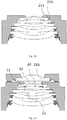
- Fig. 8 shows a schematic cross-sectional view of an optical lens according to another embodiment of the present application.
- the spacer ring 214 between the lenses is replaced by a glue film 215b (for example, an EVA glue film).
- the glue film 215b can be made into the shape of the spacer ring 214 to replace the function of the spacer ring 214.
- the glue film 215b is made opaque (for example, set to be black), so that the glue film 215b has the function of blocking light, thereby forming a diaphragm between the lenses to prevent stray light from interfering with the imaging result.
- the glue film 215b since the glue film 215b has adhesiveness, the glue film 215b functions to bond the lenses after being pressed by the adjacent lenses during the lens assembling, thereby reinforcing the structural strength of the lens assembling.
- the plurality of lenses assembled into the lens group include embedded reinforcement lenses, and the adhesive material 215 is provided between the embedded reinforcement lenses and the lens barrel.
- an outer surface of the embedded reinforcement lens may include an inclined surface 221 (or called an inclined segment), and the inclined surface 221 can form a wedge-shaped gap with the inner surface of the lens barrel (for example, the step side wall 211a), the glue 215a can be arranged in the wedge-shaped gap, so as to reinforce the structural strength of the lens group.
- Fig. 9 shows another embodiment of adhesive reinforcement between the embedded reinforcement lens and the lens barrel. Referring to Fig.
- a structure zone of the embedded reinforcement lens may include a protrusion, and an outer surface of the protrusion and the inner surface of the lens barrel may form a glue containing groove 213, specifically, in Fig. 9 , the outer surface of the protrusion, the step surface 211b and the step side wall 211a of the lens barrel together form the glue containing groove 213. Glue is arranged in the glue containing groove 213.
- Fig. 10 shows a complete lens group assembly having the glue containing groove 213 shown in Fig. 9 .
- the lens group assembly can be used as the second lens component 200.
- the lens group assembly shown in Fig. 10 can replace the second lens component 200 in the embodiment of Fig. 1 to form another optical lens 1000 assembled based on the active calibration process.
- the adhesive material 215 can be arranged in an annular shape (for example, the flow guide groove 212 or the glue containing groove 213 can be annular shaped in a plan view), or may be distributed at several points in an annular area (for example, a flow guide groove 212 or a glue containing groove 213 can be provided in each of the four directions inside the lens barrel.
- the plurality of lenses assembled into the lens group includes a first fitting lens 10 and a second fitting lens 20 adjacent to each other.
- Fig. 11 shows a schematic diagram of an optical lens having the first fitting lens 10 and the second fitting lens 20 adjacent to each other.
- a structure zone of the first fitting lens 10 has a first fitting protrusion 11
- a structure zone of the second fitting lens 20 has a second fitting protrusion 21
- the first fitting protrusion 11 and the second fitting protrusion 21 are staggered from each other, and the adhesive material 215 is arranged on a fitting gap formed between an inner surface of the first fitting protrusion 11 and an outer surfaces of the second fitting protrusion 21.
- the adhesive material is bonded between the structural zones of the three lenses at the front end of the lens group to reinforce the structural strength of the assembled lens group.
- any one or more of the three lenses at the front end can be bonded with the lens barrel to reinforce the structural strength of the lens group.
- the adhesive materials can be arranged between the lenses and between the lenses and the lens barrel to enhance the reinforcement effect.
- the front end refers to the end of the lens group or optical lens close to the object.
- a lens group assembling method which includes:
- the process of embedding the plurality of lenses into the lens barrel in step 1) includes: inverting the lens barrel, and embedding the first lens into the first step inside the lens barrel, and then embedding the second lens into the second step inside the lens barrel, and then embedding the next lens into the next step, and repeating until all the lenses are inserted into the lens barrel.
- Structural zones of two adjacent lenses can directly lean each other, or they can bear each other through a spacer ring 214 (e.g., a SOMA sheet).
- the spacer ring 214 e.g., a SOMA sheet.
- the embedding process of the two lenses is added with the step of arranging the spacer ring 214.
- the former lens is first embedded in the lens barrel, then the spacer ring 214 is arranged on the surface of the structure zone of the former lens, and then the next lens is inserted in the lens barrel.
- the step 2) includes any one or more of sub-steps a), b), and c), and the sub-steps a), b), and c) are as follows.
- the adhesive material 215 may be glue 215a.
- the glue 215a may be arranged in a groove formed between the spacer ring 214 and the lens (referring to the former lens).
- the spacer ring 214 may have a concave 214a as shown in Fig. 4 , and a groove is formed between the concave 214a and the lens.
- the arrangement method of the glue 215a may include: after embedding the former lens, arranging a spacer ring on the surface of the structure zone of the former lens, wherein the spacer ring has a concave 214a, and the concave 214a is recessed from outside to inside along the direction perpendicular to the optical axis, an area of the surface of the former lens corresponding to the position of the concave 214a is exposed; then arranging the glue 215a in the area corresponding to the position of the concave 214a, and finally embedding the latter lens.
- the adhesive material may be a glue film 215b.
- the glue film 215b can be made into the shape of the spacer ring 214 to replace the function of the spacer ring 214.
- the glue film 215b is made opaque (for example, set to be black), so that the glue film 215b has a function of blocking light, thereby forming a diaphragm between the lenses to prevent stray light from interfering with the imaging result.
- the glue film 215b since the glue film 215b has adhesiveness, the glue film 215b acts to bond the lenses after being pressed by the adjacent lenses during the lens assembling, thereby reinforcing the structural strength of the lens assembling.
- the plurality of lenses assembled into the lens group include the adjacent first fitting lens 10 and second fitting lens 20 as shown in Fig. 11 .
- the structure zone of the first fitting lens 10 has a first fitting protrusion 11
- the structure zone of the second fitting lens 20 has a second fitting protrusion 21.
- glue 215a is arranged on the surface of the structure zone of the first fitting lens 10 close to the inner surface of the first fitting protrusion 11.
- the second fitting lens 20 is embedded into the lens barrel, and the first fitting protrusion 11 and the second fitting protrusion 21 are staggered with each other, so that the glue 215a is located on a fitting gap formed between the inner surface of the first fitting protrusion 11 and the outer surface of the second fitting protrusion 21.
- b) for two adjacent lenses after embedding the former lens, arranging the glue 215a between the lens (the former lens) and the lens barrel, and then embedding the latter lens.
- the lens adhered with the lens barrel through the glue 215a is referred to as an embedded reinforcement lens.
- the outer surface of the embedded reinforcement lens may include the inclined surface (or called the inclined segment), and the inclined surface may form the wedge-shaped gap with the inner surface of the lens barrel (for example, the step side wall 211a), the glue 215a can be arranged in the wedge-shaped gap, so as to reinforce the structural strength of the lens group.
- Fig. 9 shows another embodiment of the embedded reinforcement lens and the lens barrel for bonding and reinforcing.
- a structure zone of the embedded reinforcement lens may include a protrusion, and an outer surface of the protrusion and the inner surface of the lens barrel may form a glue containing groove 213, specifically, in Fig.
- the outer surface of the protrusion forms the glue containing groove 213 with the step surface 211b and the step side wall 211a of the lens barrel together.
- the glue 215a is arranged in the glue containing groove 213. c) after two adjacent (or more) lenses are embedded in the lens barrel, arranging the glue 215a through a flow guide channel provided on the inner side surface of the lens barrel, so that the glue 215a enters a gap between the structural zones of two (or more) adjacent lenses.
- the flow guide channel communicates with at least two adjacent steps of the multi-step steps 211 of the lens barrel, so as to be suitable for the glue 215a to flow between the at least two adjacent steps.
- the flow guide channel may be a flow guide groove 212, and the flow guide groove 212 is a recessed structure located on the inner side of the lens barrel.
- the gap between the flow guide groove 212 and the outer surface of the lens can be filled with glue 215a to form a structural reinforcement for the assembled lens group.
- the adhesive material 215 may be UV glue/UV thermosetting glue, thermosetting glue, moisture curing glue, anaerobic glue or solvent evaporative curing glue.
- an area where the glue 215a is arranged is an edge area of the lens, which is far away from the optical zone of the lens.
- the adhesive material 215 has a relatively small viscosity, for example, the viscosity is 500 or less. Viscosity represents the degree of dilution of glue 215a. The lower the viscosity is, the better the fluidity is.
- the thixotropic coefficient of the glue 215a is within 1.2.
- the thixotropy coefficient represents the thixotropy, which refers to the characteristic that the shear stress of the glue 215a (or called glue solution) decreases over time under the action of a certain shear rate.
- the glue 215a with a thixotropic coefficient of less than 1.2 has specific performance in the adhesion process: under agitation, the viscosity of the glue solution drops rapidly, which is convenient for painting; when the agitation is stopped, the viscosity of the glue solution increases immediately and will not flow randomly, and the viscosity is relatively thin to use, and it is easy to scrape.
- the flow guide channel is used to arrange the glue 215a to the position between the lenses.
- the above sub-steps a), b), and c) correspond to several different methods of using the adhesive material to reinforce the lens group.
- one of these reinforcement methods can be used alone, multiple of the above reinforcement methods can also be used in combination.
- the active calibration described in this application can adjust a relative position of the first lens component 100 and the second lens component 200 in multiple degrees of freedom.
- Fig. 12A shows a relative position adjustment manner in the active calibration in an embodiment of the present application.
- the first lens component 100 (or the first lens 101) can move relative to the second lens component 200 along x, y, and z directions (that is, the adjustment has three degrees of freedom for the relative position in this embodiment).
- the z direction is the direction along the optical axis
- the x and y directions are the directions perpendicular to the optical axis.
- the x and y directions are both in an adjustment plane P, and in the adjustment plane P, the translation can be decomposed into two components in the x and y directions.
- Fig. 12B shows a rotation adjustment in the active calibration of another embodiment of the present application.
- the relative position adjustment in addition to the three degrees of freedom of Fig. 12A , the relative position adjustment also adds a degree of freedom of rotation, that is, adjustment in r direction.
- the adjustment in the r-direction is a rotation in the adjustment plane P, that is, a rotation around an axis perpendicular to the adjustment plane P.
- Fig. 12C shows a relative position adjustment manner in the active calibration according to another embodiment of the present application with addition of v and w direction adjustments.
- the v direction represents a rotation angle of a xoz plane
- the w direction represents a rotation angle of a yoz plane
- the rotation angles of the v direction and the w direction can be combined into a vector angle
- this vector angle represents a total tilt state.
- a tilt posture of the first lens component 100 relative to the second lens component 200 can be adjusted (that is, the tilt of the optical axis of the first lens component 100 with respect to the optical axis of the second lens component 200).
- the adjustment of the six degrees of freedom of x, y, z, r, v, and w described above may all affect the imaging quality of the optical system (for example, affect the size of the resolution).
- the relative position adjustment manner may be to adjust only any one of the above six degrees of freedom, or a combination of any two or more of them.
- the adjustment of the relative position of the first lens component and the second lens component includes translation on the adjustment plane, that is, movement in the x and y directions.
- the adjustment of the relative positions of the first lens component 100 and the second lens component 200 further includes: according to a measured resolution of the optical system, adjusting and determining an angle between the axis of the first lens component 100 and the axis of the second lens component 200, that is, the adjustment in the w and v directions.
- adjusting the relative position of the first lens component 100 and the second lens component 200 further includes: moving the first lens component 100 in a direction perpendicular to the adjustment plane (i.e., adjustment in the z direction), according to the measured resolution of the optical system, determining the relative position between the first lens component 100 and the second lens component 200 in the direction perpendicular to the adjustment plane.
- the first lens component 100 may not have the first lens barrel 110.
- the first lens component 100 may be constituted of a single first lens 120.
- a corresponding predetermined positioning is first performed, so that there is a gap between the bottom surface of the first lens 120 and the top surface of the second lens component 200; then the active calibration is performed, and then the adhesive material is arranged on the gap and solidified.
- the first lens 120 may be formed by a plurality of sub-lenses that are embedded with each other to form a whole.
- a side surface and a top surface of the non-optical surface of the first lens 120 that are not used for imaging may form a light shielding layer.
- the light shielding layer may be formed by screen printing a light shielding material on the side and top surface of the first lens 120.
- the second lens component 200 in the active calibration step, can be fixed, the first lens component 100 can be clamped by a clamp, and the first lens component 100 can be moved under drive of a six-axis motion mechanism connected to the clamp, thereby the relative movement between the first lens component 100 and the second lens component 200 in the above six degrees of freedom is realized.
- the clamp can be leaned against or partially leaned against the side surface of the first lens component 100, thereby clamping the first lens component 100 and performing position adjustment with multiple degrees of freedom.
Landscapes
- Physics & Mathematics (AREA)
- General Physics & Mathematics (AREA)
- Optics & Photonics (AREA)
- Engineering & Computer Science (AREA)
- Multimedia (AREA)
- Signal Processing (AREA)
- Lens Barrels (AREA)
Abstract
Description
- This application claims the priority and benefits of the Chinese invention patent application filed in the China National Intellectual Property Office (CNIPA) on August 14, 2018, with application number
201810922696.1 201821305574.X - The present application relates to the technical field of optical imaging. Specifically, the present application relates to a lens group assembly, an optical lens, a camera module, and a lens group assembling method.
- With the development of mobile phones, computers and other terminals, users have greatly improved their needs. Especially with the development of mobile phones, users' pursuit of shooting quality has led manufacturers to develop personalized and customized camera modules, such as a lens with a large aperture, a large wide-angle, and a lens with a large number of lenses that solve aberrations. On one hand, this is more and more complicated in optical design, on the other hand, the reality is that the complex optical system is very sensitive, which poses large challenge to the manufacturing yield and product quality. Because the optical system of a camera module with a large aperture and a large wide-angle is more sensitive, the reliability of its manufacturing process and verification process will be more fragile than conventional designs. Therefore, a lens with a better structure is now needed. Further, in order to meet more and more extensive market demands, high pixels, small size, and large aperture are the irreversible development trends of existing camera modules. However, it is very difficult to achieve the three requirements of high pixels, small size, and large aperture in a same camera module. For example, the compact development of mobile phones and the increase in the proportion of mobile phone screens have made the space available for front camera modules in mobile phones smaller and smaller, and the market has proposed higher and higher demands for the imaging quality of camera modules.
- In the field of compact camera modules (such as those used in mobile phones), it is often necessary to consider the quality of an optical imaging lens and manufacturing errors in the module packaging process. Specifically, in the manufacturing process of the optical imaging lens, the factors affecting the resolution of the lens come from the errors of each element and its assembly, the error of the thickness of the lens spacing element, the error of the assembly fit of each lens, and the change of the refractive index of the lens material. Because there are many factors that affect the resolution of the lens, which exist in multiple elements, the control of each factor has the limit of manufacturing accuracy. If you just simply improve the accuracy of each element, the improving capacity is limited, the upgrade cost is high, and it cannot meet the increasing demand for improved imaging quality in the market.
- The applicant proposes an assembly method of adjusting and determining a relative position of upper and lower sub-lens based on an active calibration process, and then adhering the upper and lower sub-lens together according to the determined relative position, thereby manufacturing a complete optical lens or camera module. This solution can improve the Process Capability Index (CPK) of mass-produced optical lenses or camera modules; it can loosen the requirements for the accuracy of each element of the material (such as the sub-lens or photosensitive assemblies used to assemble optical lenses or camera modules) and its assembly accuracy, thereby reducing the overall cost of the optical imaging lens and camera module; adjusting various aberrations of the camera module in real time during the assembly process, reducing the defect rate, reducing production costs, and improving imaging quality.
- However, actively calibrating the optical system of the lens itself is a new production process. Actual mass production needs to consider many factors such as the reliability, drop resistance, weather resistance and production cost of the optical lens and camera module, and sometimes it is necessary to face a decrease in yield caused by various unpredictable factors. The applicant believes that improving the structural reliability of optical lenses manufactured based on the active calibration process is an important direction for thinking about improving the imaging quality and yield of such optical lenses. Therefore, there is an urgent need for a solution that can improve the structural reliability of the optical lens manufactured based on the active calibration process.
- This application aims to provide a solution that can overcome at least one defect of the prior art.
- According to one aspect of the present application, there is provided a lens group assembly, including: a lens barrel; and a plurality of lenses, the plurality of lenses are embedded in the lens barrel to assemble a lens group, and there is an adhesive material between at least two lenses of the plurality of lenses and/or between at least one lens of the plurality of lenses and the lens barrels to reinforce a structural strength of the assembled lens group.
- Wherein, the plurality of lenses has three lenses at a front end, and the adhesive material is arranged between at least two lenses of the three lenses at the front end and/or between at least one lens of the three lenses at the front end and the lens barrels.
- Wherein, the lens has an optical zone and a structural zone surrounding the optical zone, and the plurality of lenses includes two adjacent adhesive reinforcement lenses, and there is the adhesive material between the structural zones of the two adjacent adhesive reinforcement lenses.
- Wherein, the lens has an optical zone and a structural zone surrounding the optical zone, and the plurality of lenses include adjacent first fitting lenses and second fitting lens, the structure zone of the first fitting lens has a first fitting protrusion, the structure zone of the second fitting lens has a second fitting protrusion, and the first fitting protrusion and the second fitting protrusion are staggered with each other, and the adhesive material is arranged in a fitting gap formed between an inner surface of the first fitting protrusion and an outer surface of the second fitting protrusion.
- Wherein, the adhesive material includes glue and/or glue film.
- Wherein, when the adhesive material is glue, the glue is glue with a thixotropic coefficient within 1.2 and a viscosity below 500.
- Wherein, when the adhesive material is glue, the plurality of lenses include two adjacent adhesive reinforcement lenses, and a spacer ring is arranged between the two adjacent adhesive reinforcement lenses, the spacer ring has a notch and the notch contains the glue.
- Wherein, when the adhesive material is glue film, the plurality of lenses include two adjacent adhesive reinforcement lenses, and the two adjacent adhesive reinforcement lenses are adhesived by the glue film.
- Wherein, the plurality of lenses include an embedded reinforced lens, and the adhesive material is provided between the embedded reinforced lens and the lens barrel.
- Wherein, an inner side of the lens barrel has multi-level steps, and the plurality of lenses are sequentially embedded in the multi-level steps.
- Wherein, each step in the multi-level steps includes a step side wall and a step surface, wherein the step side wall is parallel to the axis of the lens barrel, and the step surface is perpendicular to the axis of the lens barrel.
- Wherein, the adhesive material is glue, the inner side of the lens barrel has a flow guide channel, and the flow guide channel communicates with at least two adjacent steps of the multi-level steps, so as to be suitable for the flow of glue between the at least two adjacent steps, and the flow guide channel is filled with the glue.
- Wherein, the flow guide channel is a flow guide groove, and the embedded reinforcement lens is provided at least one step corresponding to the flow guide groove, and a gap between an outer surface of the embedded reinforcement lens and the flow guide groove is filled with the adhesive material.
- Wherein, the adhesive material is arranged in a ring shape, or the adhesive material is distributed at a plurality of points in the ring shape.
- Wherein, the adhesive material is an UV glue, an UV thermosetting glue, a thermosetting glue, a moisture curing glue, an anaerobic glue or a solvent evaporative curing glue.
- According to another aspect of the present application, there also provides an optical lens, including: a first lens component, including at least one first lens; a second lens component, including a second lens barrel and at least one second lens mounted in the second lens barrel, and the at least one second lens and the at least one first lens constitute an imageable optical system together; and an active calibration adhesive glue, which is located between the first lens component and the second lens component, and is adapted to support the first lens component and the second lens component so that a relative position of the two is maintained at a relative position determined by active calibration; wherein the second lens component is the lens group assembly described above, and the second lens barrel is the lens barrel of the lens group assembly, and the at least one second lens is the plurality of lenses of the lens group assembly.
- Wherein, the first lens component further includes a first lens barrel, and the at least one first lens is mounted in the first lens barrel.
- Wherein, the first lens component is the lens group assembly, and the first lens barrel is the lens barrel of the lens group assembly, and the at least one first lens is the plurality of lenses of the lens group assembly.
- Wherein, the first lens component is located at the front end of the optical lens.
- Wherein, a non-zero included angle is between the axis of the first lens component and the axis of the second lens component.
- According to another aspect of the present application, a camera module is also provided, which includes the lens group assembly described above.
- According to another aspect of the present application, another camera module is provided, which includes the aforementioned optical lens.
- According to another aspect of the present application, there also provides a lens group assembling method, including: 1) sequentially embedding a plurality of lenses into a lens barrel with multi-level steps at an inner side thereof to assemble a lens group; and 2) during the execution of step 1) or after completion of step 1), adding the adhesive material between at least two lenses of the plurality of lenses and/or between at least one lens of the plurality of lenses and the lens barrel to reinforce an structural strength of the assembled lens group.
- Wherein, the step 2) includes the sub-steps: a) for two adjacent lenses of the plurality of lenses, after the former lens is embedded, arranging an adhesive material on a surface of a structure zone of the former lens, and then embedding the latter lens.
- Wherein, the step 2) includes sub-steps: b) for two adjacent lenses of the plurality of lenses, after the former lens is embedded, arranging glue between the former lens and the lens barrel, and then embedding the latter lens.
- Wherein, the step 2) includes the sub-steps: c) the adhesive material being glue, and after the adjacent lenses of the plurality of lenses are embedded in the lens barrel, arranging glue through a flow guide channel provided at the inner side of the lens barrel, so that the glue enters a gap between the structural zones of the adjacent lenses along the flow guide channel.
- Wherein, in the step a), the adhesive material is glue, and the step a) further includes: after the former lens is embedded, arranging a spacer ring on the surface of the structure zone of the former lens, and the spacer ring having a concave, wherein the concave is recessed from outside to inside along a direction perpendicular to the optical axis, and the area of the surface of the former lens corresponding to the position of the concave is exposed; then arranging the glue on the area of the former lens corresponding to the position of the concave; and finally embedding the latter lens.
- Wherein, in the step a), the adhesive material is glue film, and the glue film forms a diaphragm.
- Compared with the prior art, the present application has at least one of the following technical effects:
- 1. The present application can improve the assembling accuracy and assembling stability of a high-sensitivity multi-lens optical system by increasing the adhesion between the lenses (for example, using glue/glue film reinforcement).
- 2. The present application can increase the connection strength of the lens group to reduce the variation of the optical lens based on the active calibration process.
- 3. The present invention can accommodate the adhesive material that might otherwise overflow through structural design such as the reserved gap on the side wall of the lens dark object (such as the lens barrel) and the spacer ring gap, and enhance the connection strength between the lens and the dark object, and between the lens and the lens at the same time.
- The present application can increase the adhering strength of the lower lens group to reduce the defects caused by the assembly of the optical lens based on the active calibration process, and especially reduce the field curvature and peak variation.
- Exemplary examples are shown in the referenced drawings. The examples and drawings disclosed herein should be regarded as illustrative rather than restrictive.
-
Fig. 1 shows a schematic cross-sectional view of anoptical lens 1000 according to an embodiment of the present application; -
Fig. 2 shows a schematic diagram of embedding the first lens into a lens barrel in an embodiment of the present application; -
Fig. 3 shows a schematic diagram of providing aspacer ring 214 on a bottom surface of the lens; -
Fig. 4 shows a schematic bottom view of thespacer ring 214 provided; -
Fig. 5 shows a schematic diagram of embedding the second lens into the lens barrel; -
Fig. 6 shows a schematic diagram of a lens barrel with a flow guide channel on an inner side thereof and embedding a lens in the lens barrel; -
Fig. 7 shows a schematic bottom view of the flow guide channel located in the lens barrel in an embodiment of the present application; -
Fig. 8 shows a schematic cross-sectional view of an optical lens according to another embodiment of the present application; -
Fig. 9 shows another example of adhering reinforcement between embedded reinforcement lens and a lens barrel; -
Fig. 10 shows a complete lens group assembly with theglue containing groove 213 shown inFig. 9 ; -
Fig. 11 shows a schematic diagram of an optical lens with a firstfitting lens 10 and a secondfitting lens 20 adjacent to each other; -
Fig. 12A shows a relative position adjustment manner in an active calibration in an embodiment of the present application; -
Fig. 12B shows a relative position adjustment manner in the active calibration in an embodiment of the present application; -
Fig. 12C shows a relative position adjustment manner in the active calibration according to another embodiment of the present application, which adds adjustment in v and w directions. - In order to better understand the present application, various aspects of the application will be described in more detail with reference to the drawings. It should be understood that these detailed descriptions are only descriptions of exemplary embodiments of the present application, and are not intended to limit the scope of the present application in any way. Throughout the specification, the same reference numerals refer to the same elements. The expression "and/or" includes any and all combinations of one or more of the associated listed items.
- It should be noted that in this specification, expressions such as first, second, etc. are only used to distinguish one feature from another feature, and do not represent any restriction on the feature. Therefore, without departing from the teaching of the present application, the first subject discussed below may also be referred to as the second subject.
- In the drawings, the thickness, size, and shape of objects have been slightly exaggerated for ease of description. The drawings are only examples and are not drawn strictly to scale.
- It should also be understood that the terms "include", "include with", "having", "including" and/or " including with" when used in this specification mean that the stated features, wholes, steps, operations elements and/or components exist, but does not exclude the presence or addition of one or more other features, wholes, steps, operations, elements, components, and/or combinations thereof. In addition, when expressions such as "at least one of......" appear after the list of listed features, the entire listed feature is modified instead of individual elements in the list. In addition, at the time of describing the embodiments of the present application, the use of "may" means "one or more embodiments of the present application". Also, the term "exemplary" is intended to refer to an example or illustration.
- As used herein, the terms "substantially," "approximately," and similar terms are used as approximate terms, not as terms representing degree, and it is also intended to illustrate the inherent deviations in the measured or calculated values that will be recognized by those of ordinary skill in the art.
- Unless otherwise defined, all terms (including technical terms and scientific terms) used herein have the same meanings as commonly understood by those of ordinary skill in the art to which this application belongs. It should also be understood that terms (such as those defined in commonly used dictionaries) should be interpreted as having meanings consistent with their meanings in the context of related technologies, and will not be interpreted in an idealized or excessively formal sense, unless this is clearly defined in this article.
- It should be noted that the embodiments in the application and the features in the embodiments can be combined with each other if there is no conflict. Hereinafter, the present application will be described in detail with reference to the drawings and in conjunction with embodiments.
-
Fig. 1 shows a schematic cross-sectional view of anoptical lens 1000 according to an embodiment of the present application. As shown inFig. 1 , theoptical lens 1000 of this embodiment includes afirst lens component 100, asecond lens component 200 and an adhesive 300 for bonding thefirst component 100 andsecond lens components 200. The adhesive 300 is suitable for supporting the first and second lens components after being cured and keeping a relative position between the two at a relative position determined by an active calibration. Therefore, the adhesive 300 can be called an active calibration adhesive, in order to distinguish from other plastic materials. The other adhesive material mentioned here may be, for example, anadhesive material 215 used to reinforce the structure of the lens group which will be mentioned below. Herein, the active calibration is a manufacturing process of calibrating the relative positions of thefirst lens component 100 and thesecond lens component 200 with multiple degrees of freedom based on an imaging result of a photosensitive chip. The specific method of the active calibration will be further detailed below, the description will not be expanded here. In this embodiment, thefirst lens component 100 includes afirst lens barrel 110 and afirst lens 120 mounted in the first lens barrel 110 (the number of thefirst lens 120 in this embodiment is one, but it should be noted that the present application is not limited to this, and there can also be multiple first lenses 120). Thesecond lens component 200 includes asecond lens barrel 210 and a plurality ofsecond lenses 220 mounted in thesecond lens barrel 210. Thefirst lens 120 and the plurality ofsecond lenses 220 together constitute an imageable optical system. In this embodiment, thesecond lens component 200 is a lens group assembly that increases the strength of the connection between the lenses. Specifically, in this embodiment, a plurality ofsecond lenses 220 are embedded in thesecond lens barrel 210 to assemble a lens group, and there is anadhesive material 215 between the two adjacentsecond lenses 220 at the bottom to reinforce the structural strength of the assembled lens group. It should be noted that what is shown inFig. 1 is only one way to reinforce the structural strength of the lens group. In other embodiments of the present application, an adhesive material may be provided between at least two lenses of the plurality ofsecond lenses 220 in other ways to reinforce the structural strength of the assembled lens group; it is also possible to provide theadhesive material 215 between at least one lens of the plurality ofsecond lenses 220 and the lens barrel to reinforce the structural strength of the assembled lens group; it is also possible to provide theadhesive material 215 between at least two lenses of the plurality ofsecond lenses 220, and between at least one lens of the plurality of lenses and the lens barrel to reinforce the structural strength of the assembled lens group. For the plurality of lenses, they are embedded into a same lens barrel to assemble a lens group, and theadhesive material 215 is used to increase the connection strength between the lenses during lens assembling, which can improve the assembling accuracy and assembling stability of the high-sensitivity optical system. In one embodiment, thefirst lens component 100 is located at the front end of theoptical lens 1000, that is, at an end close to the object, and thesecond lens component 200 is located at the rear end of theoptical lens 1000. - Further, still referring to
Fig. 1 , in an embodiment of the present application, the lens has an optical zone and a structural zone surrounding the optical zone. Wherein, the lens includes thefirst lens 120 or thesecond lens 220. In the lens group assembly, the plurality of lenses includes two adjacent adhesive reinforcement lenses, and theadhesive material 215 is provided between the structural zones of the two adjacent adhesive reinforcement lenses. - Further, in an embodiment of the present application, an inner side of the
second lens barrel 210 may havemulti-level steps 211.Fig. 2 shows a schematic diagram of embedding the first lens into the lens barrel in an embodiment of the present application. Referring toFig. 2 , the inner side of the lens barrel (for example, the second lens barrel 210) hasmulti-level steps 211, and the plurality of lenses are sequentially embedded in themulti-level steps 211. Each of themulti-level steps 211 includes astep side wall 211a and astep surface 211b, wherein thestep side wall 211a is parallel to the axis of the lens barrel, and thestep surface 211b is perpendicular to the axis of the lens barrel. - Further, in an embodiment of the present application, the lens group assembly includes two adjacent adhesive reinforcement lenses, and a
spacer ring 214 is provided between the two adjacent adhesive reinforcement lenses. Thespacer ring 214 may have a notch and the notch accommodates theglue 215a. Still referring toFig. 2 , the first lens is embedded in the first step of the lens barrel. An outer surface of the structure zone of the lens leans against thestep side wall 211a of the first step, and a top surface of the structure zone (when the plurality of lenses are assembled into a lens group, the lens barrel and the lens are usually inverted, so the top surface of the structure zone inFig. 2 is at the bottom of the lens). In this embodiment, a bottom surface of the structural zone of the lens may have a protrusion (inFig. 2 , the lens is inverted, so the protrusion is convex upward). Furthermore,Fig. 3 shows a schematic diagram of aspacer ring 214 provided on the bottom surface of the lens.Fig. 4 shows a schematic bottom view of thespacer ring 214 provided. Referring toFig. 4 , thespacer ring 214 has a notch, and the notch may be a concave 214a that is recessed from outside to inside. When thespacer ring 214 is arranged on the bottom surface of the lens, a gap can be formed between the groove and the structure zone of the first lens, and the gap can accommodate theadhesive material 215. In other embodiments, the gap accommodating theadhesive material 215 may also be formed between the groove and the lens barrel (for example, thestep side wall 211a of the lens barrel). Theadhesive material 215 is arranged in the gap. In this embodiment, theadhesive material 215 may be aglue 215a. Further,Fig. 5 shows a schematic diagram of embedding the second lens into the lens barrel. Wherein, the second lens and the first lens can lean each other through thespacer ring 214 to assemble a composite body with stable optical performance. Referring toFig. 5 , the adhesive material is located between the two lenses to reinforce the structural strength of the composite body of the two lenses. The two lenses inFig. 5 are adhesive reinforcement lenses. In a lens group assembly, there can be multiple groups of adjacent adhesive reinforcement lenses. - Further, in one embodiment, a SOMA sheet can be fixed by being fitted between the lenses, or it can be placed inside without force. In particular, the SOMA sheet is designed to have a notched shape. The notch of the SOMA sheet can be used as a mark for machine vision recognition (machine vision here is used to identify a starting point of gluing), and it can also be a space for the
glue 215a. - Further, in an embodiment of the present application, the inner surface of the lens barrel has a flow guide channel.
Fig. 6 shows a schematic diagram of a lens barrel with a flow guide channel on the inner surface thereof and a lens embedded in the lens barrel. Referring toFig. 6 , the flow guide channel communicates with at least two adjacent steps of themulti-step steps 211 of the lens barrel, so as to be suitable for theglue 215a to flow between the at least two adjacent steps. The flow guide channel is filled with theglue 215a.Fig. 7 shows a schematic bottom view of the flow guide channel located in the lens barrel in an embodiment of the present application. Referring toFig. 7 , the flow guide channel may be aflow guide groove 212, and theflow guide groove 212 is a recessed structure located on the inner side of the lens barrel. A gap between theflow guide groove 212 and the outer surface of the lens can be filled with theglue 215a to form a structural reinforcement for the assembled lens group. In this embodiment, theadhesive material 215 may be UV glue/UV thermosetting glue, thermosetting glue, moisture curing glue, anaerobic glue or solvent evaporative curing glue. An area where the glue is laid is an edge area of the lens, which is far from the optical zone of the lens. In this embodiment, theadhesive material 215 has a relatively small viscosity, for example, the viscosity is 500 or less. Viscosity represents the degree of dilution of theglue 215a. The lower the viscosity is, the better the fluidity is. The thixotropic coefficient of theglue 215a is within 1.2. The thixotropy coefficient represents the thixotropy, which refers to the characteristic that the shear stress of theglue 215a (or called glue solution) decreases over time under the action of a certain shear rate. The specific performance of the glue with a thixotropic coefficient within 1.2 in the adhesive process is: under agitation, the viscosity of the glue solution drops rapidly, which is convenient for painting; when it is stopped, the viscosity of the glue solution increases immediately and will not flow randomly, and the viscosity is relatively thin when used, and easy to scrape. - In one embodiment, the
adhesive material 215 may be underfill glue. The underfill glue isglue 215a suitable for a underfill process, and its thixotropic coefficient is within 1.2. - Further, in one embodiment, a recessed depth of the
flow guide groove 212 inside the lens barrel is greater than 20 µm, and a width of theflow guide groove 212 is greater than 20 µm (the specific design size of the flow guide groove can be determined according to the lens size and the properties of the adhesive material). Theglue 215a flows through the flow guide channel to bond adjacent lenses, and bond the lenses and the lens barrel, thereby enhancing the connection strength of the assembled lens group. -
Fig. 8 shows a schematic cross-sectional view of an optical lens according to another embodiment of the present application. In this embodiment, thespacer ring 214 between the lenses is replaced by aglue film 215b (for example, an EVA glue film). In other words, theglue film 215b can be made into the shape of thespacer ring 214 to replace the function of thespacer ring 214. For example, theglue film 215b is made opaque (for example, set to be black), so that theglue film 215b has the function of blocking light, thereby forming a diaphragm between the lenses to prevent stray light from interfering with the imaging result. On the other hand, since theglue film 215b has adhesiveness, theglue film 215b functions to bond the lenses after being pressed by the adjacent lenses during the lens assembling, thereby reinforcing the structural strength of the lens assembling. - Further, in an embodiment of the present application, the plurality of lenses assembled into the lens group include embedded reinforcement lenses, and the
adhesive material 215 is provided between the embedded reinforcement lenses and the lens barrel. Referring toFig. 2 , in an embodiment, an outer surface of the embedded reinforcement lens may include an inclined surface 221 (or called an inclined segment), and theinclined surface 221 can form a wedge-shaped gap with the inner surface of the lens barrel (for example, thestep side wall 211a), theglue 215a can be arranged in the wedge-shaped gap, so as to reinforce the structural strength of the lens group.Fig. 9 shows another embodiment of adhesive reinforcement between the embedded reinforcement lens and the lens barrel. Referring toFig. 9 , in another embodiment, a structure zone of the embedded reinforcement lens may include a protrusion, and an outer surface of the protrusion and the inner surface of the lens barrel may form aglue containing groove 213, specifically, inFig. 9 , the outer surface of the protrusion, thestep surface 211b and thestep side wall 211a of the lens barrel together form theglue containing groove 213. Glue is arranged in theglue containing groove 213. Further,Fig. 10 shows a complete lens group assembly having theglue containing groove 213 shown inFig. 9 . The lens group assembly can be used as thesecond lens component 200. For example, the lens group assembly shown inFig. 10 can replace thesecond lens component 200 in the embodiment ofFig. 1 to form anotheroptical lens 1000 assembled based on the active calibration process. - Further, in the above-mentioned embodiment, the
adhesive material 215 can be arranged in an annular shape (for example, theflow guide groove 212 or theglue containing groove 213 can be annular shaped in a plan view), or may be distributed at several points in an annular area (for example, aflow guide groove 212 or aglue containing groove 213 can be provided in each of the four directions inside the lens barrel. - Further, in an embodiment of the present application, the plurality of lenses assembled into the lens group includes a first
fitting lens 10 and a secondfitting lens 20 adjacent to each other.Fig. 11 shows a schematic diagram of an optical lens having the firstfitting lens 10 and the secondfitting lens 20 adjacent to each other. Referring toFig. 11 , a structure zone of the firstfitting lens 10 has a firstfitting protrusion 11, and a structure zone of the secondfitting lens 20 has a secondfitting protrusion 21, The firstfitting protrusion 11 and the secondfitting protrusion 21 are staggered from each other, and theadhesive material 215 is arranged on a fitting gap formed between an inner surface of the firstfitting protrusion 11 and an outer surfaces of the secondfitting protrusion 21. - Further, in an embodiment of the present application, the adhesive material is bonded between the structural zones of the three lenses at the front end of the lens group to reinforce the structural strength of the assembled lens group. In another embodiment, any one or more of the three lenses at the front end can be bonded with the lens barrel to reinforce the structural strength of the lens group. Further, for the above three lenses at the front end, the adhesive materials can be arranged between the lenses and between the lenses and the lens barrel to enhance the reinforcement effect. When the number of lenses in the lens group is large, for example, four or more than four, since the optical sensitivity of the first three lenses is relatively high, the assembling structure strength of the first three lenses can be reinforced, which can better improve the reliability of the active calibration process and optical lens imaging. Herein, the front end refers to the end of the lens group or optical lens close to the object.
- Further, according to an embodiment of the present application, there also provides a lens group assembling method, which includes:
- 1) embedding a plurality of lenses into a lens barrel with
multi-level steps 211 at an inner side thereof to assemble a lens group; and - 2) during the execution of step 1) or after the embedding step is completed, adding an
adhesive material 215 between at least two lenses of the plurality of lenses and/or at least one lenses of the plurality of lenses and the lens barrels to reinforce the structural strength of the assembled lens group. - Wherein, the process of embedding the plurality of lenses into the lens barrel in step 1) includes: inverting the lens barrel, and embedding the first lens into the first step inside the lens barrel, and then embedding the second lens into the second step inside the lens barrel, and then embedding the next lens into the next step, and repeating until all the lenses are inserted into the lens barrel. Structural zones of two adjacent lenses can directly lean each other, or they can bear each other through a spacer ring 214 (e.g., a SOMA sheet). When the structural zones of two adjacent lenses are leaned together by the
spacer ring 214, the embedding process of the two lenses is added with the step of arranging thespacer ring 214. For example, the former lens is first embedded in the lens barrel, then thespacer ring 214 is arranged on the surface of the structure zone of the former lens, and then the next lens is inserted in the lens barrel. - Further, in some embodiments of the present application, the step 2) includes any one or more of sub-steps a), b), and c), and the sub-steps a), b), and c) are as follows.
- a) for two adjacent lenses, in the process of embedding the two lenses into the lens barrel, arranging the
adhesive material 215 between the two lenses. That is, for two adjacent lenses, after the former lens is embedded, theadhesive material 215 is arranged on the surface of the structure zone of the lens (referring to the former lens) (in the embedding step, the lens barrel and the lens are usually inverted, so the surface here is usually a bottom surface). Then the latter lens is embedded. - In an embodiment, the
adhesive material 215 may beglue 215a. Preferably, in order to prevent theglue 215a from polluting the optical zone, theglue 215a may be arranged in a groove formed between thespacer ring 214 and the lens (referring to the former lens). Thespacer ring 214 may have a concave 214a as shown inFig. 4 , and a groove is formed between the concave 214a and the lens. The arrangement method of theglue 215a may include: after embedding the former lens, arranging a spacer ring on the surface of the structure zone of the former lens, wherein the spacer ring has a concave 214a, and the concave 214a is recessed from outside to inside along the direction perpendicular to the optical axis, an area of the surface of the former lens corresponding to the position of the concave 214a is exposed; then arranging theglue 215a in the area corresponding to the position of the concave 214a, and finally embedding the latter lens. - In another embodiment, the adhesive material may be a
glue film 215b. Theglue film 215b can be made into the shape of thespacer ring 214 to replace the function of thespacer ring 214. For example, theglue film 215b is made opaque (for example, set to be black), so that theglue film 215b has a function of blocking light, thereby forming a diaphragm between the lenses to prevent stray light from interfering with the imaging result. On the other hand, since theglue film 215b has adhesiveness, theglue film 215b acts to bond the lenses after being pressed by the adjacent lenses during the lens assembling, thereby reinforcing the structural strength of the lens assembling. - In another embodiment, the plurality of lenses assembled into the lens group include the adjacent first
fitting lens 10 and secondfitting lens 20 as shown inFig. 11 . The structure zone of the firstfitting lens 10 has a firstfitting protrusion 11, and the structure zone of the secondfitting lens 20 has a secondfitting protrusion 21. After the first fitting lens 10 (i.e., the former lens) is embedded,glue 215a is arranged on the surface of the structure zone of the firstfitting lens 10 close to the inner surface of the firstfitting protrusion 11. Then the secondfitting lens 20 is embedded into the lens barrel, and the firstfitting protrusion 11 and the secondfitting protrusion 21 are staggered with each other, so that theglue 215a is located on a fitting gap formed between the inner surface of the firstfitting protrusion 11 and the outer surface of the secondfitting protrusion 21.
b) for two adjacent lenses, after embedding the former lens, arranging theglue 215a between the lens (the former lens) and the lens barrel, and then embedding the latter lens. For ease of description, sometimes the lens adhered with the lens barrel through theglue 215a is referred to as an embedded reinforcement lens. - As shown in
Fig. 2 , in an example, the outer surface of the embedded reinforcement lens may include the inclined surface (or called the inclined segment), and the inclined surface may form the wedge-shaped gap with the inner surface of the lens barrel (for example, thestep side wall 211a), theglue 215a can be arranged in the wedge-shaped gap, so as to reinforce the structural strength of the lens group.Fig. 9 shows another embodiment of the embedded reinforcement lens and the lens barrel for bonding and reinforcing. Referring toFig. 9 , in another embodiment, a structure zone of the embedded reinforcement lens may include a protrusion, and an outer surface of the protrusion and the inner surface of the lens barrel may form aglue containing groove 213, specifically, inFig. 9 , the outer surface of the protrusion forms theglue containing groove 213 with thestep surface 211b and thestep side wall 211a of the lens barrel together. Theglue 215a is arranged in theglue containing groove 213.
c) after two adjacent (or more) lenses are embedded in the lens barrel, arranging theglue 215a through a flow guide channel provided on the inner side surface of the lens barrel, so that theglue 215a enters a gap between the structural zones of two (or more) adjacent lenses. - Referring to
Fig. 6 , the flow guide channel communicates with at least two adjacent steps of themulti-step steps 211 of the lens barrel, so as to be suitable for theglue 215a to flow between the at least two adjacent steps. Referring toFig. 7 , the flow guide channel may be aflow guide groove 212, and theflow guide groove 212 is a recessed structure located on the inner side of the lens barrel. The gap between theflow guide groove 212 and the outer surface of the lens can be filled withglue 215a to form a structural reinforcement for the assembled lens group. In this embodiment, theadhesive material 215 may be UV glue/UV thermosetting glue, thermosetting glue, moisture curing glue, anaerobic glue or solvent evaporative curing glue. An area where theglue 215a is arranged is an edge area of the lens, which is far away from the optical zone of the lens. In this embodiment, theadhesive material 215 has a relatively small viscosity, for example, the viscosity is 500 or less. Viscosity represents the degree of dilution ofglue 215a. The lower the viscosity is, the better the fluidity is. The thixotropic coefficient of theglue 215a is within 1.2. The thixotropy coefficient represents the thixotropy, which refers to the characteristic that the shear stress of theglue 215a (or called glue solution) decreases over time under the action of a certain shear rate. Theglue 215a with a thixotropic coefficient of less than 1.2 has specific performance in the adhesion process: under agitation, the viscosity of the glue solution drops rapidly, which is convenient for painting; when the agitation is stopped, the viscosity of the glue solution increases immediately and will not flow randomly, and the viscosity is relatively thin to use, and it is easy to scrape. In this embodiment, after the plurality of lenses are embedded in the lens barrel, the flow guide channel is used to arrange theglue 215a to the position between the lenses. - It should be noted that the above sub-steps a), b), and c) correspond to several different methods of using the adhesive material to reinforce the lens group. In the assembling process of the lens group, one of these reinforcement methods can be used alone, multiple of the above reinforcement methods can also be used in combination.
- The following will further introduce the active calibration process used in the optical lens or camera module assembly method.
- The active calibration described in this application can adjust a relative position of the
first lens component 100 and thesecond lens component 200 in multiple degrees of freedom.Fig. 12A shows a relative position adjustment manner in the active calibration in an embodiment of the present application. In this adjustment manner, the first lens component 100 (or the first lens 101) can move relative to thesecond lens component 200 along x, y, and z directions (that is, the adjustment has three degrees of freedom for the relative position in this embodiment). The z direction is the direction along the optical axis, and the x and y directions are the directions perpendicular to the optical axis. The x and y directions are both in an adjustment plane P, and in the adjustment plane P, the translation can be decomposed into two components in the x and y directions. -
Fig. 12B shows a rotation adjustment in the active calibration of another embodiment of the present application. In this embodiment, in addition to the three degrees of freedom ofFig. 12A , the relative position adjustment also adds a degree of freedom of rotation, that is, adjustment in r direction. In this embodiment, the adjustment in the r-direction is a rotation in the adjustment plane P, that is, a rotation around an axis perpendicular to the adjustment plane P. - Further,
Fig. 12C shows a relative position adjustment manner in the active calibration according to another embodiment of the present application with addition of v and w direction adjustments. Wherein, the v direction represents a rotation angle of a xoz plane, the w direction represents a rotation angle of a yoz plane, the rotation angles of the v direction and the w direction can be combined into a vector angle, and this vector angle represents a total tilt state. In other words, by adjusting the v and w directions, a tilt posture of thefirst lens component 100 relative to thesecond lens component 200 can be adjusted (that is, the tilt of the optical axis of thefirst lens component 100 with respect to the optical axis of the second lens component 200). - The adjustment of the six degrees of freedom of x, y, z, r, v, and w described above may all affect the imaging quality of the optical system (for example, affect the size of the resolution). In other embodiments of the present application, the relative position adjustment manner may be to adjust only any one of the above six degrees of freedom, or a combination of any two or more of them.
- Further, in one embodiment, in the active calibration step, the adjustment of the relative position of the first lens component and the second lens component includes translation on the adjustment plane, that is, movement in the x and y directions.
- Further, in one embodiment, in the active calibration step, the adjustment of the relative positions of the
first lens component 100 and thesecond lens component 200 further includes: according to a measured resolution of the optical system, adjusting and determining an angle between the axis of thefirst lens component 100 and the axis of thesecond lens component 200, that is, the adjustment in the w and v directions. In the assembled optical lens or camera module, there is a non-zero included angle between the axis of thefirst lens component 100 and the axis of thesecond lens component 200. - Further, in an embodiment, in the active calibration step, adjusting the relative position of the
first lens component 100 and thesecond lens component 200 further includes: moving thefirst lens component 100 in a direction perpendicular to the adjustment plane (i.e., adjustment in the z direction), according to the measured resolution of the optical system, determining the relative position between thefirst lens component 100 and thesecond lens component 200 in the direction perpendicular to the adjustment plane. - Further, in an embodiment, the
first lens component 100 may not have thefirst lens barrel 110. For example, thefirst lens component 100 may be constituted of a singlefirst lens 120. Before the active calibration, a corresponding predetermined positioning is first performed, so that there is a gap between the bottom surface of thefirst lens 120 and the top surface of thesecond lens component 200; then the active calibration is performed, and then the adhesive material is arranged on the gap and solidified. In this embodiment, thefirst lens 120 may be formed by a plurality of sub-lenses that are embedded with each other to form a whole. In this embodiment, a side surface and a top surface of the non-optical surface of thefirst lens 120 that are not used for imaging may form a light shielding layer. The light shielding layer may be formed by screen printing a light shielding material on the side and top surface of thefirst lens 120. - In one embodiment, in the active calibration step, the
second lens component 200 can be fixed, thefirst lens component 100 can be clamped by a clamp, and thefirst lens component 100 can be moved under drive of a six-axis motion mechanism connected to the clamp, thereby the relative movement between thefirst lens component 100 and thesecond lens component 200 in the above six degrees of freedom is realized. Wherein, the clamp can be leaned against or partially leaned against the side surface of thefirst lens component 100, thereby clamping thefirst lens component 100 and performing position adjustment with multiple degrees of freedom. - The above description is only a preferred embodiment of the application and an explanation of the applied technical principles. Those skilled in the art should understand that the scope of the invention involved in this application is not limited to the technical solution formed by the specific combination of the above technical features, and should also cover other technical solutions formed by any combination of the above technical features or their equivalent features without departing from the stated concept of the invention. For example, the above-mentioned features and the technical features disclosed in this application (but not limited to) with similar functions are mutually replaced to form a technical solution.
Claims (28)
- A lens group assembly, characterized by comprising:a lens barrel; anda plurality of lenses, wherein the plurality of lenses are embedded in the lens barrel to assemble a lens group, and there is an adhesive material between at least two lenses of the plurality of lenses and/or between at least one lens of the plurality of lenses and the lens barrels to reinforce the structural strength of the assembled lens group.
- The lens group assembly according to claim 1, wherein the plurality of lenses have three lenses at the front end, and the adhesive material is between at least two lenses of the three lenses at the front end and/or between at least one lens of the three lenses at the front end and the lens barrel.
- The lens group assembly according to claim 2, wherein the lens has an optical zone and a structural zone surrounding the optical zone, and the plurality of lenses includes two adjacent adhesive reinforcement lenses, and the adhesive material is between the structural zones of the two adjacent adhesive reinforcement lenses.
- The lens group assembly according to claim 2, wherein the lens has an optical zone and a structural zone surrounding the optical zone, and the plurality of lenses include adjacent first fitting lenses and second fitting lens, and the structure zone of the first fitting lens has a first fitting protrusion, and the structure zone of the second fitting lens has a second fitting protrusion, and the first fitting protrusion and the second fitting protrusion are staggered with each other, and the adhesive material is arranged in a fitting gap formed between an inner surface of the first fitting protrusion and an outer surface of the second fitting protrusion.
- The lens group assembly according to claim 2, wherein the adhesive material includes glue and/or glue film.
- The lens group assembly according to claim 5, wherein in case that the adhesive material is glue, the glue is glue with a thixotropic coefficient within 1.2 and a viscosity below 500.
- The lens group assembly according to claim 5, wherein when in case that the adhesive material is glue, the plurality of lenses include two adjacent adhesive reinforcement lenses, and a spacer ring is arranged between the two adjacent adhesive reinforcement lenses, and the spacer ring has a notch and the notch contains the glue.
- The lens group assembly according to claim 5, wherein in case that the adhesive material is a glue film, the plurality of lenses include two adjacent adhesive reinforcement lenses, and the two adjacent adhesive reinforcement lenses are adhesived by the glue film.
- The lens group assembly according to claim 1, wherein the plurality of lenses include an embedded reinforcement lenses, and the adhesive material is provided between the embedded reinforcement lens and the lens barrel.
- The lens group assembly according to claim 1, wherein an inner side of the lens barrel has multi-level steps, and the plurality of lenses are sequentially embedded in the multi-level steps.
- The lens group assembly according to claim 10, wherein each step in the multi-level steps includes a step side wall and a step surface, wherein the step side wall is parallel to the axis of the lens barrel, and the step surface is perpendicular to the axis of the lens barrel.
- The lens group assembly according to claim 11, wherein the adhesive material is glue, and the inner side of the lens barrel is provided with a flow guide channel, and the flow guide channel communicates with at least two adjacent steps of the multi-level steps, so as to be suitable for the flow of the glue between the at least two adjacent steps, and the flow guide channel is filled with the glue.
- The lens group assembly according to claim 12, wherein the flow guide channel is a flow guide groove, and at least one step corresponding to the flow guide groove is arranged with the embedded reinforcement lens, and a gap between an outer surface of the embedded reinforcement lens and the flow guide groove is filled with the adhesive material.
- The lens group assembly according to claim 1, wherein the adhesive material is arranged in a ring shape, or the adhesive material is distributed at a plurality of points in the ring shape.
- The lens group assembly according to claim 1, wherein the adhesive material is an UV glue, an UV thermosetting glue, a thermosetting glue, a moisture curing glue, an anaerobic glue or a solvent evaporative curing glue.
- An optical lens, characterized by comprising:a first lens component including at least one first lens;a second lens component including a second lens barrel and at least one second lens mounted in the second lens barrel, wherein the at least one second lens and the at least one first lens constitute an imageable optical system together; andan active calibration adhesive glue, which is located between the first lens component and the second lens component, and is adapted to support the first lens component and the second lens component so that a relative position of the first lens component and the second lens component is maintained at a relative position determined by an active calibration;wherein, the second lens component is the lens group assembly according to any one of claims 1-15,and the second lens barrel is the lens barrel of the lens group assembly, and the at least one second lens is the plurality of lenses of the lens group assembly.
- The optical lens of claim 16, wherein the first lens component further includes a first lens barrel, and the at least one first lens is mounted in the first lens barrel.
- The optical lens of claim 17, wherein the first lens component is the lens group assembly, and the first lens barrel is the lens barrel of the lens group assembly, and the at least one first lens is the plurality of lenses of the lens group assembly.
- The optical lens of claim 16, wherein the first lens component is located at the front end of the optical lens.
- The optical lens of claim 16, wherein a non-zero included angle is between the axis of the first lens component and the axis of the second lens component.
- A camera module, characterized by comprising the lens group assembly according to any one of claims 1-15.
- A camera module, characterized by comprising the optical lens according to any one of claims 16-20.
- A lens group assembling method, characterized by comprising:1) embedding a plurality of lenses into a lens barrel with multi-level steps at an inner side thereof to assemble a lens group; and2) during the execution of step 1) or after the completion of step 1), adding an adhesive material between at least two lenses of the plurality of lenses and/or between at least one lens of the plurality of lenses and the lens barrel to reinforce the structural strength of the assembled lens group.
- The lens group assembling method of claim 23, wherein the step 2) includes sub-steps:a) for two adjacent lenses of the plurality of lenses, after a former lens is embedded, arranging an adhesive material on a surface of a structure zone of the former lens, and then embedding a latter lens.
- The lens group assembling method according to claim 23, wherein the step 2) includes sub-steps:
b) for two adjacent lenses of the plurality of lenses, after the former lens is embedded, arranging an adhesive material between the former lens and the lens barrel, and then embedding the latter lens. - The lens group assembling method of claim 23, wherein the step 2) includes sub-steps:
c) the adhesive material being glue, and after the adjacent lenses of the plurality of lenses are embedded in the lens barrel, arranging the glue through a flow guide channel provided at an inner side of the lens barrel so that the glue enters a gap between structural zones of the adjacent lenses along the flow guide channel. - The lens group assembling method according to claim 24, wherein in the step a), the adhesive material is glue, and the step a) further includes: after the former lens is embedded, arranging a spacer ring on the surface of the structure zone of the former lens, wherein the spacer ring has a concave, and the concave is recessed from outside to inside along a direction perpendicular to the optical axis, and an area of the surface of the former lens corresponding to the position of the concave is exposed; then arranging the glue on the area of the former lens corresponding to the position of the concave; and finally embedding the latter lens.
- The lens group assembling method according to claim 24, wherein in the step a), the adhesive material is a glue film, and the glue film forms a diaphragm.
Applications Claiming Priority (3)
| Application Number | Priority Date | Filing Date | Title |
|---|---|---|---|
| CN201810922696.1A CN110824657B (en) | 2018-08-14 | 2018-08-14 | Lens group assembly, optical lens, camera module and lens group assembly method |
| CN201821305574.XU CN209842189U (en) | 2018-08-14 | 2018-08-14 | Lens group assembly, optical lens and camera module |
| PCT/CN2019/095390 WO2020034790A1 (en) | 2018-08-14 | 2019-07-10 | Lens set assembly, optical lens, camera module, and lens set assembly method |
Publications (2)
| Publication Number | Publication Date |
|---|---|
| EP3828610A1 true EP3828610A1 (en) | 2021-06-02 |
| EP3828610A4 EP3828610A4 (en) | 2021-09-15 |
Family
ID=69525100
Family Applications (1)
| Application Number | Title | Priority Date | Filing Date |
|---|---|---|---|
| EP19849325.6A Pending EP3828610A4 (en) | 2018-08-14 | 2019-07-10 | LENS SET ARRANGEMENT, OPTICAL LENS, CAMERA MODULE AND METHOD OF ASSEMBLING A LENS SET ARRANGEMENT |
Country Status (5)
| Country | Link |
|---|---|
| US (1) | US12055786B2 (en) |
| EP (1) | EP3828610A4 (en) |
| JP (1) | JP2021534453A (en) |
| KR (1) | KR20210041071A (en) |
| WO (1) | WO2020034790A1 (en) |
Cited By (1)
| Publication number | Priority date | Publication date | Assignee | Title |
|---|---|---|---|---|
| US12493197B2 (en) | 2022-01-04 | 2025-12-09 | Meta Platforms Technologies, Llc | Camera device assembled with lens-to-sensor distance that reduces auto-focusing actuation power in macro mode |
Families Citing this family (8)
| Publication number | Priority date | Publication date | Assignee | Title |
|---|---|---|---|---|
| CN111665604B (en) * | 2019-03-05 | 2022-09-06 | 微软技术许可有限责任公司 | Lens system and imaging device |
| CN112346192B (en) * | 2020-09-25 | 2025-05-09 | 江西欧菲光学有限公司 | Lenses and electronic devices |
| KR102632348B1 (en) * | 2021-04-06 | 2024-02-02 | 삼성전기주식회사 | Lens assembly |
| CN116055850B (en) * | 2021-10-27 | 2025-07-15 | 宁波舜宇光电信息有限公司 | Camera module, assembly method and electronic equipment |
| US20230168463A1 (en) * | 2021-11-26 | 2023-06-01 | Canon Kabushiki Kaisha | Optical element, optical device, and image pickup apparatus |
| KR20250005585A (en) * | 2023-07-03 | 2025-01-10 | 삼성전기주식회사 | Solvent composition for welding optical module and camera module using the same |
| TWI855783B (en) * | 2023-07-19 | 2024-09-11 | 大陸商榮諭科技(成都)有限公司 | Lens set and processing method |
| CN118131430B (en) * | 2024-03-19 | 2024-11-19 | 北京极溯光学科技有限公司 | A glued lens and an extended reality display |
Family Cites Families (16)
| Publication number | Priority date | Publication date | Assignee | Title |
|---|---|---|---|---|
| JPH06347610A (en) * | 1993-06-11 | 1994-12-22 | Nikon Corp | Joined lens |
| CN101285921A (en) * | 2007-04-13 | 2008-10-15 | 鸿富锦精密工业(深圳)有限公司 | Imaging module |
| JP2010191345A (en) | 2009-02-20 | 2010-09-02 | Hitachi Maxell Ltd | Lens unit, camera module, and method for manufacturing lens unit |
| CN102016678A (en) * | 2009-04-06 | 2011-04-13 | 松下电器产业株式会社 | Lens unit |
| JP5322782B2 (en) * | 2009-06-04 | 2013-10-23 | 日立マクセル株式会社 | Lens unit, camera module, and lens unit manufacturing method |
| JP5118674B2 (en) * | 2009-08-28 | 2013-01-16 | シャープ株式会社 | Optical element module and manufacturing method thereof, electronic element module and manufacturing method thereof, and electronic information device |
| MX376360B (en) * | 2012-11-14 | 2025-03-07 | Ehs Lens Philippines Inc | METHOD FOR THE MANUFACTURE OF POLARIZING PLASTIC LENSES. |
| JP6217193B2 (en) * | 2013-07-09 | 2017-10-25 | 株式会社デンソー | Optical lens device |
| EP3370098B1 (en) | 2015-10-30 | 2022-12-14 | Ningbo Sunny Opotech Co., Ltd. | Manufacturing method for a camera module |
| CN205594217U (en) * | 2016-03-03 | 2016-09-21 | 宁波舜宇光电信息有限公司 | Optical lens of integrated motor and module of making a video recording and make tool thereof |
| JP6862146B2 (en) * | 2016-11-04 | 2021-04-21 | キヤノン株式会社 | Optical equipment |
| JP6758170B2 (en) | 2016-12-08 | 2020-09-23 | 日本電産サンキョー株式会社 | Lens unit and imaging device |
| JP6825898B2 (en) | 2016-12-16 | 2021-02-03 | マクセル株式会社 | Laminated lens and camera module |
| CN108254849B (en) * | 2016-12-29 | 2020-10-27 | 玉晶光电(厦门)有限公司 | Optical lens group |
| CN207249220U (en) * | 2017-03-24 | 2018-04-17 | 宁波舜宇光电信息有限公司 | Split type camera lens and camera module and electronic equipment |
| CN108375819A (en) * | 2018-02-09 | 2018-08-07 | 瑞声科技(新加坡)有限公司 | Lens assembly and its assemble method |
-
2019
- 2019-07-10 US US17/268,191 patent/US12055786B2/en active Active
- 2019-07-10 KR KR1020217007598A patent/KR20210041071A/en not_active Ceased
- 2019-07-10 JP JP2021507627A patent/JP2021534453A/en active Pending
- 2019-07-10 WO PCT/CN2019/095390 patent/WO2020034790A1/en not_active Ceased
- 2019-07-10 EP EP19849325.6A patent/EP3828610A4/en active Pending
Cited By (1)
| Publication number | Priority date | Publication date | Assignee | Title |
|---|---|---|---|---|
| US12493197B2 (en) | 2022-01-04 | 2025-12-09 | Meta Platforms Technologies, Llc | Camera device assembled with lens-to-sensor distance that reduces auto-focusing actuation power in macro mode |
Also Published As
| Publication number | Publication date |
|---|---|
| KR20210041071A (en) | 2021-04-14 |
| EP3828610A4 (en) | 2021-09-15 |
| US20210318512A1 (en) | 2021-10-14 |
| WO2020034790A1 (en) | 2020-02-20 |
| US12055786B2 (en) | 2024-08-06 |
| JP2021534453A (en) | 2021-12-09 |
Similar Documents
| Publication | Publication Date | Title |
|---|---|---|
| US12055786B2 (en) | Lens group assembly, optical lens, camera module and lens group assembling method | |
| US8913181B2 (en) | Camera module and method for assembling same | |
| US12510723B2 (en) | Optical lens, camera module and assembly method therefor | |
| CN208432778U (en) | Optical lens and camera module | |
| EP3848740B1 (en) | Integrated lens barrel, optical lens, camera module, and assembly method | |
| CN112649933B (en) | Optical lens, camera module and assembly method thereof | |
| CN110573923B (en) | Multi-group lens, camera module, assembling method of camera module and electronic equipment | |
| WO2023071732A1 (en) | Optical lens and corresponding camera module | |
| US8077404B2 (en) | Optical unit | |
| CN110412707A (en) | Optical lens, camera module and assembly method thereof | |
| CN209842189U (en) | Lens group assembly, optical lens and camera module | |
| CN110824657B (en) | Lens group assembly, optical lens, camera module and lens group assembly method | |
| CN110542969B (en) | Optical lens, camera module and assembling method thereof | |
| CN110557523A (en) | Camera module array and assembling method thereof | |
| WO2019228348A1 (en) | Optical lens, and camera module and assembly method thereof | |
| US12117664B2 (en) | Optical lens, camera module and assembling method | |
| CN112534328B (en) | Optical lens, camera module and assembly method thereof | |
| EP2476542A2 (en) | Method of manufacturing lens and lens manufactured using the same |
Legal Events
| Date | Code | Title | Description |
|---|---|---|---|
| STAA | Information on the status of an ep patent application or granted ep patent |
Free format text: STATUS: THE INTERNATIONAL PUBLICATION HAS BEEN MADE |
|
| PUAI | Public reference made under article 153(3) epc to a published international application that has entered the european phase |
Free format text: ORIGINAL CODE: 0009012 |
|
| STAA | Information on the status of an ep patent application or granted ep patent |
Free format text: STATUS: REQUEST FOR EXAMINATION WAS MADE |
|
| 17P | Request for examination filed |
Effective date: 20210225 |
|
| AK | Designated contracting states |
Kind code of ref document: A1 Designated state(s): AL AT BE BG CH CY CZ DE DK EE ES FI FR GB GR HR HU IE IS IT LI LT LU LV MC MK MT NL NO PL PT RO RS SE SI SK SM TR |
|
| A4 | Supplementary search report drawn up and despatched |
Effective date: 20210817 |
|
| RIC1 | Information provided on ipc code assigned before grant |
Ipc: G02B 7/02 20210101AFI20210811BHEP |
|
| DAV | Request for validation of the european patent (deleted) | ||
| DAX | Request for extension of the european patent (deleted) | ||
| P01 | Opt-out of the competence of the unified patent court (upc) registered |
Effective date: 20230524 |
|
| STAA | Information on the status of an ep patent application or granted ep patent |
Free format text: STATUS: EXAMINATION IS IN PROGRESS |
|
| 17Q | First examination report despatched |
Effective date: 20231024 |