EP3828558A1 - Over the air measuring device with feed switcher positioner - Google Patents
Over the air measuring device with feed switcher positioner Download PDFInfo
- Publication number
- EP3828558A1 EP3828558A1 EP19212373.5A EP19212373A EP3828558A1 EP 3828558 A1 EP3828558 A1 EP 3828558A1 EP 19212373 A EP19212373 A EP 19212373A EP 3828558 A1 EP3828558 A1 EP 3828558A1
- Authority
- EP
- European Patent Office
- Prior art keywords
- feed antenna
- over
- sub
- antenna devices
- measuring device
- Prior art date
- Legal status (The legal status is an assumption and is not a legal conclusion. Google has not performed a legal analysis and makes no representation as to the accuracy of the status listed.)
- Granted
Links
Images


Classifications
-
- G—PHYSICS
- G01—MEASURING; TESTING
- G01R—MEASURING ELECTRIC VARIABLES; MEASURING MAGNETIC VARIABLES
- G01R31/00—Arrangements for testing electric properties; Arrangements for locating electric faults; Arrangements for electrical testing characterised by what is being tested not provided for elsewhere
- G01R31/28—Testing of electronic circuits, e.g. by signal tracer
- G01R31/302—Contactless testing
- G01R31/308—Contactless testing using non-ionising electromagnetic radiation, e.g. optical radiation
-
- H—ELECTRICITY
- H04—ELECTRIC COMMUNICATION TECHNIQUE
- H04B—TRANSMISSION
- H04B17/00—Monitoring; Testing
- H04B17/10—Monitoring; Testing of transmitters
- H04B17/101—Monitoring; Testing of transmitters for measurement of specific parameters of the transmitter or components thereof
- H04B17/103—Reflected power, e.g. return loss
-
- G—PHYSICS
- G01—MEASURING; TESTING
- G01R—MEASURING ELECTRIC VARIABLES; MEASURING MAGNETIC VARIABLES
- G01R29/00—Arrangements for measuring or indicating electric quantities not covered by groups G01R19/00 - G01R27/00
- G01R29/08—Measuring electromagnetic field characteristics
- G01R29/0864—Measuring electromagnetic field characteristics characterised by constructional or functional features
- G01R29/0878—Sensors; antennas; probes; detectors
-
- H—ELECTRICITY
- H01—ELECTRIC ELEMENTS
- H01Q—ANTENNAS, i.e. RADIO AERIALS
- H01Q1/00—Details of, or arrangements associated with, antennas
- H01Q1/12—Supports; Mounting means
- H01Q1/22—Supports; Mounting means by structural association with other equipment or articles
- H01Q1/225—Supports; Mounting means by structural association with other equipment or articles used in level-measurement devices, e.g. for level gauge measurement
-
- G—PHYSICS
- G01—MEASURING; TESTING
- G01R—MEASURING ELECTRIC VARIABLES; MEASURING MAGNETIC VARIABLES
- G01R29/00—Arrangements for measuring or indicating electric quantities not covered by groups G01R19/00 - G01R27/00
- G01R29/08—Measuring electromagnetic field characteristics
- G01R29/0864—Measuring electromagnetic field characteristics characterised by constructional or functional features
- G01R29/0871—Complete apparatus or systems; circuits, e.g. receivers or amplifiers
Definitions
- the present invention relates to automatically performing over the air measurements on a device under test throughout a wide frequency range.
- a feed antenna When performing over the air measurements on a device under test, a feed antenna is used for transmitting a measuring signal to the device under test or for receiving a measuring signal from the device under test.
- a feed antenna has a usable frequency range.
- Modern communications standards though are specified for very wide frequency ranges, possibly exceeding the usable frequency range of a single feed antenna. For this reason, measuring systems using a plurality of interchangeable feed antennas can be used.
- the object of the invention is to provide an over the air measuring device and system, which allows for performing measurements on a device under test in a large frequency range while requiring only minimal operator involvement.
- an over the air measuring device comprises N feed antenna devices, a measuring device, adapted to perform over the air measurements on a device under test, selectively using any one of the N feed antenna devices, and a guide rail adapted to moveably hold the N feed antenna devices, the N feed antenna devices being independently movable along the guide rail. This allows for moving a presently used feed antenna device into a suitable position for performing a measurement while at the same time storing the remaining feed antenna devices. This allows for an over the air measurement, requiring only minimal operator involvement.
- the N feed antenna devices are each adapted to transmit first measuring signals to the device under test over the air, and/or receive second measuring signals from the device under test, over the air. Additionally, the measuring device is adapted to generate the first measuring signals and/or measure the second measuring signals. This allows for a very efficient conducting of the measurements.
- the over the air measuring device comprises a reflector, which is adapted to reflect the first measuring signals after being transmitted, before reaching the device under test, and/or to reflect the second measuring signals after being transmitted, before reaching the one of the N feed antennas performing the measurement.
- a reflector which is adapted to reflect the first measuring signals after being transmitted, before reaching the device under test, and/or to reflect the second measuring signals after being transmitted, before reaching the one of the N feed antennas performing the measurement.
- the guide rail comprises a feed antenna device measurement location, adapted to hold any one of the N feed antenna devices during a measurement using said one of the N feed antenna devices.
- a position of a feed antenna of said any one of the N feed antenna devices in the antenna device measuring location is a focal point of the reflector. This allows for achieving far-field conditions at the position of the device under test.
- the over the air measuring device is adapted to perform measurements using only one of the N feed antenna simultaneously. Additionally or alternatively, the over the air measuring device is adapted to perform successive measurements using at least two of the N feed antenna devices. This allows for an automatic measurement in a frequency range larger than the frequency range of a single feed antenna.
- the guide rail comprises at least one feed antenna device storage area, adapted to store N-1 of the N feed antenna devices side by side during a measurement using any one of the N feed antenna devices.
- the guide rail comprises a feed antenna device measurement location, adapted to hold one of the N feed antenna devices during a measurement using said one of the N feed antenna devices. This allows for a very compact geometry of the over the air measuring device.
- a distance between any one of the N feed antenna devices being held at the feed antenna device measurement location and any of the further N-1 feed antenna devices being held in the feed antenna device storage area is larger than a distance between any two of the further N-1 feed antenna devices being held in the feed antenna device storage area. This prevents interference between the feed antenna being used for the present measurement and the remaining feed antennas not being used, presently.
- the guide rail is of a linear shape or of an oval shape or of a U-shape or of a partly linear and partly semi-circular shape. This allows for a very flexible systems design and a compact geometry of the over the air measuring device.
- the guide rail is adapted to position the N feed antenna devices individually using at least one linear motor or at least one stepper motor. This allows for an especially high degree of automation and thereby and especially low operator involvement.
- the N feed antenna devices each comprise alignment means, adapted to hold the feed antenna devices on the guide rail. This allows for an especially accurate positioning.
- the N feed antenna devices each comprise securing means, preferably mechanical means or a magnet, adapted to secure the respective feed antenna device in a feed antenna device measuring location along the guide rail. This allows for an especially exact positioning while performing the measurement.
- the N feed antenna devices and the guide rail are arranged within an anechoic chamber comprised by the over the air measuring device.
- the measuring device though, is arranged outside of the anechoic chamber. This allows for an especially compact design of the over the air measuring device while at the same time achieving a high tolerance with regard to interference.
- the over the air measuring device additionally comprises a device under test holder, adapted to hold the device under test.
- the device under test holder is a 3D-positioner, adapted to orient the device under test successively in a plurality of orientations. This allows for an especially high degree of automation, further reducing operator involvement.
- the over the air measuring device is adapted to successively position at least two of the N feed antenna devices in a feed antenna device measuring location along the guide rail, successively orient the device under test in a plurality of orientations for every of said feed antennas, and perform a measurement on the device under test using the measuring device at every of said plurality of orientations.
- an over the air measuring system comprising a previously described over the air measuring device and a device under test is provided.
- Such an over the air measuring system allows for the performing of measurements on the device under test over a large frequency range while requiring only minimal operator involvement.
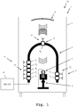
- FIG. 1 an embodiment of the inventive over the air measuring system 10 comprising a first embodiment of the inventive over the air measuring device 1 and a device under test 7 is shown.
- the over the air measuring device 1 comprises an anechoic chamber 3, and housed therein a guide rail 2 and N feed antenna devices 6 1 , 6 2 , 6 3 , 6 4 , 6 5 , 6 6 , 6 7 and 6 8 , jointly referred to using the reference number 6.
- the guide rail 2 movably holds the N feed antenna devices 6.
- the N feed antenna devices 6 are independently movable along the guide rail 2.
- the anechoic chamber 3 houses a device under test holder 5, which is advantageously a 3D-positioner.
- the device under test holder 5 holds the device under test 7 in a specified position.
- the device under test holder 5 is preferably adapted to move and orient the device under test 7 into a plurality of different positions and/or orientations.
- the over the air measuring device 1 comprises a measuring device 8, which is located outside of the anechoic chamber 3. It is important to note that the anechoic chamber 3 is an optional component. The over the air measuring device 1 is completely functional even without the anechoic chamber 3.
- the over the air measuring device 1 comprises the anechoic chamber 3
- the anechoic chamber 3 is preferably arranged on wheels so that it can easily be moved around in a lab-environment.
- the measuring device 8 is attached to the outside of the anechoic chamber 3, facilitating the movement of the over the air measuring device 1.
- the anechoic chamber 3 is of a width smaller than a typical door frame, especially smaller than 1.2 m, most preferably smaller than 0.8 m.
- Fig. 1 a frontal view of the over the air measuring device 1 and the over the air measuring system 10 is shown
- Fig. 2 shows a side-view of the same.
- the guide rail along with the feed antenna devices 6 and the device under test holder 5 along with the device under test 7 are not arranged in the same plane. While they are displayed side by side in the side-view of Fig. 2 , they are arranged behind each other in the frontal view of Fig. 1 .
- one of the feed antenna devices 6 is moved along the guide rail 2 into a feed antenna device measuring position 11.
- the remaining feed antenna devices 6 are moved to at least one, in this embodiment two, feed antenna device storage areas 12 along the guide rail 2.
- the feed antenna device measuring position 11 advantageously is at a focal point of the reflector 4.
- the feed antenna device 6 6 in the feed antenna device measuring location 11 transmits a first measuring signal to the device under test 7.
- This first measuring signal though is transmitted not directly to the device under test 7, but is transmitted towards the reflector 4, reflected by the reflector 4, and only thereafter received by the device under test 7.
- the first measuring signal emitted by the feed antenna device 6 6 is depicted with solid lines, while the first measuring signal after reflection by the reflector 4 is depicted with dotted lines. Especially in Fig. 2 , it can be clearly seen that the first measuring signal is reflected by the reflector 4 to the device under test 7 and not back to the feed antenna device 6 6 .
- the feed antenna device 6 6 used for the measurement as well as the reflector 4 are arranged so that at the positon of the device under test 7, there are far-field conditions.
- the device under test 7 emits a second measuring signal towards the reflector 4, which reflects it towards the feed antenna device 6 6 .
- the first measuring signal is provided by the measuring device 8.
- the second measuring signal is received and measured by the measuring device 8.
- the measuring device 8 is additionally connected to the device under test 7, for example by a cable connection, for performing closed loop measurements.
- the feed antenna device 6 6 is moved from the feed antenna device measuring position 11 to the at least one feed antenna device storage area 12, freeing up the feed antenna device measuring position 11. Then, a further feed antenna device 6 is moved to the feed antenna device measuring position 11, and measurements using this feed antenna device 6 are performed.
- the feed antenna devices 6 in the at least one feed antenna device storage area 12 are arranged side by side in close proximity to each other. Especially, the distance between the feed antenna devices 6 in the feed antenna device storage area 12 is smaller, especially significantly smaller than the distance between the feed antenna device 6 6 in the feed antenna device measuring location 11 to any of the other feed antenna devices 6. This minimizes interference.
- the feed antennas of the feed antenna devices 6 in the feed antenna device storage area 12 point into a different direction, advantageously into an at least 90° different direction than a feed antenna of the feed antenna device 6 6 in the feed antenna device measuring location 11. This also reduces interference.
- the feed antenna devices 6 are independently movable along the guide rail 2. Preferably, they are automatically movable by at least one linear motor or at least one stepper motor. Moreover preferably, each of the feed antenna devices comprises alignment means for holding the feed antenna devices on the guide rail. This allows for an especially accurate positioning and movement of the feed antenna devices 6.
- each of the feed antenna devices 6 comprises securing means, preferably mechanical means like a screw or a magnet adapted to secure the feed antenna device 6 in the feed antenna device measuring location 11 along the guide rail 2. By latching into position in the feed antenna device measuring location 11, it is assured that the respective feed antenna device 6 6 does not move during measurements and is positioned perfectly.
- the feed antenna devices 6 are displayed as a single element.
- the feed antenna devices 6 consist of a feed antenna positioning device and a feed antenna, connected to each other.
- the feed antenna positioning device serves the purpose of positioning the feed antenna.
- the feed antenna positioning device is in contact with the guide rail and is independently movable along the guide rail 2.
- Fig. 3 a detail of a second embodiment of the over the air measuring device is shown.
- the guide rail 2 has a partly linear and partly semi-circular shape.
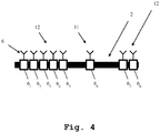
- a third embodiment of the inventive over the air measuring device is shown.
- the guide rail 2 is of a linear shape.
- feed antenna device storage areas 12 there are two feed antenna device storage areas 12. This is not to be understood as limiting. Only a single feed antenna device storage area or more than two feed antenna device storage areas may be arranged on the guide rail 2. Preferably, the number of feed antenna devices is 2 - 20, preferably 3 - 15, most preferably 4 - 10.
- the entire frequency range of measurements performed by the over the air measuring device is 1 GHz - 200 GHz, preferably 3 GHz - 100 GHz, most preferably 6 GHz - 90 GHz.
- An individual frequency range of one of the feed antenna devices is smaller than 100 GHz, preferably smaller than 50 GHz, most preferably smaller than 30 GHz.
- a first frequency range could be 6 - 23 GHz
- a second frequency range could be 40 - 60 GHz
- a third frequency range could be 60 - 90 GHz. Each of these frequency ranges would then be handled by a different feed antenna device 6.
- the positioning accuracy of the feed antenna devices 6 along the guide rail is below 10 mm, preferably below 3 mm, most preferably below 0.2 mm.
- the invention is not limited to the examples and especially not to a specific number of feed antenna devices, feed antenna device storage areas, and also not limited to specific frequencies.
- the invention discussed above can be applied to many different communication standards to be measured.
- the characteristics of the exemplary embodiments can be used in any advantageous combination.
Landscapes
- Physics & Mathematics (AREA)
- Electromagnetism (AREA)
- General Physics & Mathematics (AREA)
- Engineering & Computer Science (AREA)
- Health & Medical Sciences (AREA)
- Computer Vision & Pattern Recognition (AREA)
- Toxicology (AREA)
- General Engineering & Computer Science (AREA)
- Computer Networks & Wireless Communication (AREA)
- Signal Processing (AREA)
- Variable-Direction Aerials And Aerial Arrays (AREA)
Abstract
Description
- The present invention relates to automatically performing over the air measurements on a device under test throughout a wide frequency range.
- When performing over the air measurements on a device under test, a feed antenna is used for transmitting a measuring signal to the device under test or for receiving a measuring signal from the device under test. Such a feed antenna has a usable frequency range. Modern communications standards though are specified for very wide frequency ranges, possibly exceeding the usable frequency range of a single feed antenna. For this reason, measuring systems using a plurality of interchangeable feed antennas can be used.
- Manually exchanging the feed antenna for performing measurements at different frequency ranges though is very cumbersome and leads to a long duration of a measurement.
- In industrial automation, positioning systems are known. For example, the
document DE 10 2012 204 919 A1 shows such an automatic positioning system. - Accordingly, the object of the invention is to provide an over the air measuring device and system, which allows for performing measurements on a device under test in a large frequency range while requiring only minimal operator involvement.
- The object is solved with respect to the air measuring device by the features of the first independent claim and with respect to the system by the features of the second independent claim. Additional features of the invention are provided in the dependent claims.
- In the following, parts of the description and drawings referring to embodiments which are not covered by the claims are not presented as embodiments of the invention, but as examples useful for understanding the invention.
- According to a first aspect of the invention, an over the air measuring device is provided. The over the air measuring device comprises N feed antenna devices, a measuring device, adapted to perform over the air measurements on a device under test, selectively using any one of the N feed antenna devices, and a guide rail adapted to moveably hold the N feed antenna devices, the N feed antenna devices being independently movable along the guide rail. This allows for moving a presently used feed antenna device into a suitable position for performing a measurement while at the same time storing the remaining feed antenna devices. This allows for an over the air measurement, requiring only minimal operator involvement.
- Advantageously, the N feed antenna devices are each adapted to transmit first measuring signals to the device under test over the air, and/or receive second measuring signals from the device under test, over the air. Additionally, the measuring device is adapted to generate the first measuring signals and/or measure the second measuring signals. This allows for a very efficient conducting of the measurements.
- Preferably, the over the air measuring device comprises a reflector, which is adapted to reflect the first measuring signals after being transmitted, before reaching the device under test, and/or to reflect the second measuring signals after being transmitted, before reaching the one of the N feed antennas performing the measurement. This allows for a very compact geometry of the over the air measuring device.
- Preferably, the guide rail comprises a feed antenna device measurement location, adapted to hold any one of the N feed antenna devices during a measurement using said one of the N feed antenna devices. Additionally, a position of a feed antenna of said any one of the N feed antenna devices in the antenna device measuring location is a focal point of the reflector. This allows for achieving far-field conditions at the position of the device under test.
- Advantageously and preferably, the over the air measuring device is adapted to perform measurements using only one of the N feed antenna simultaneously. Additionally or alternatively, the over the air measuring device is adapted to perform successive measurements using at least two of the N feed antenna devices. This allows for an automatic measurement in a frequency range larger than the frequency range of a single feed antenna.
- Advantageously and preferably, the guide rail comprises at least one feed antenna device storage area, adapted to store N-1 of the N feed antenna devices side by side during a measurement using any one of the N feed antenna devices. The guide rail comprises a feed antenna device measurement location, adapted to hold one of the N feed antenna devices during a measurement using said one of the N feed antenna devices. This allows for a very compact geometry of the over the air measuring device.
- Preferably, a distance between any one of the N feed antenna devices being held at the feed antenna device measurement location and any of the further N-1 feed antenna devices being held in the feed antenna device storage area is larger than a distance between any two of the further N-1 feed antenna devices being held in the feed antenna device storage area. This prevents interference between the feed antenna being used for the present measurement and the remaining feed antennas not being used, presently.
- Preferably, the guide rail is of a linear shape or of an oval shape or of a U-shape or of a partly linear and partly semi-circular shape. This allows for a very flexible systems design and a compact geometry of the over the air measuring device.
- Advantageously, the guide rail is adapted to position the N feed antenna devices individually using at least one linear motor or at least one stepper motor. This allows for an especially high degree of automation and thereby and especially low operator involvement.
- Preferably, the N feed antenna devices each comprise alignment means, adapted to hold the feed antenna devices on the guide rail. This allows for an especially accurate positioning.
- Advantageously and preferably, the N feed antenna devices each comprise securing means, preferably mechanical means or a magnet, adapted to secure the respective feed antenna device in a feed antenna device measuring location along the guide rail. This allows for an especially exact positioning while performing the measurement.
- Advantageously and preferably, the N feed antenna devices and the guide rail are arranged within an anechoic chamber comprised by the over the air measuring device. The measuring device, though, is arranged outside of the anechoic chamber. This allows for an especially compact design of the over the air measuring device while at the same time achieving a high tolerance with regard to interference.
- Advantageously and preferably, the over the air measuring device additionally comprises a device under test holder, adapted to hold the device under test. Additionally or alternatively, the device under test holder is a 3D-positioner, adapted to orient the device under test successively in a plurality of orientations. This allows for an especially high degree of automation, further reducing operator involvement.
- Advantageously and preferably, the over the air measuring device is adapted to successively position at least two of the N feed antenna devices in a feed antenna device measuring location along the guide rail, successively orient the device under test in a plurality of orientations for every of said feed antennas, and perform a measurement on the device under test using the measuring device at every of said plurality of orientations. This allows for an especially high degree of automation, further reducing the operator involvement.
- According to a second aspect of the invention, an over the air measuring system, comprising a previously described over the air measuring device and a device under test is provided. Such an over the air measuring system allows for the performing of measurements on the device under test over a large frequency range while requiring only minimal operator involvement.
- Exemplary embodiments of the invention are now further explained with respect to the drawings, in which
- Fig. 1
- shows a first embodiment of the over the air measuring device according to the first aspect of the invention in a frontal view;
- Fig. 2
- shows the first embodiment of the over the air measuring device according to the first aspect of the invention in a side-view;
- Fig. 3
- shows a detail of a second embodiment of the over the air measuring device according to the first aspect of the invention, and
- Fig. 4
- shows a detail of a third embodiment of the over the air measuring device according to the first aspect of the invention.
- First, we demonstrate the construction and general functioning of a first embodiment of the over the air measuring device along
Fig. 1 andFig. 2 . AlongFig. 3 andFig. 4 , different shapes of the guide rail are shown and explained thereafter. Similar entities and reference numbers in different figures have been partially omitted. - In
Fig. 1 , an embodiment of the inventive over theair measuring system 10 comprising a first embodiment of the inventive over theair measuring device 1 and a device undertest 7 is shown. - The over the
air measuring device 1 comprises ananechoic chamber 3, and housed therein aguide rail 2 and Nfeed antenna devices reference number 6. Theguide rail 2 movably holds the Nfeed antenna devices 6. The Nfeed antenna devices 6 are independently movable along theguide rail 2. Moreover, theanechoic chamber 3 houses a device undertest holder 5, which is advantageously a 3D-positioner. The device undertest holder 5 holds the device undertest 7 in a specified position. The device undertest holder 5 is preferably adapted to move and orient the device undertest 7 into a plurality of different positions and/or orientations. - Additionally, the over the
air measuring device 1 comprises ameasuring device 8, which is located outside of theanechoic chamber 3. It is important to note that theanechoic chamber 3 is an optional component. The over theair measuring device 1 is completely functional even without theanechoic chamber 3. - If the over the
air measuring device 1 comprises theanechoic chamber 3, theanechoic chamber 3 is preferably arranged on wheels so that it can easily be moved around in a lab-environment. In this case, preferably, the measuringdevice 8 is attached to the outside of theanechoic chamber 3, facilitating the movement of the over theair measuring device 1. - Preferably, the
anechoic chamber 3 is of a width smaller than a typical door frame, especially smaller than 1.2 m, most preferably smaller than 0.8 m. - While in
Fig. 1 , a frontal view of the over theair measuring device 1 and the over theair measuring system 10 is shown,Fig. 2 shows a side-view of the same. InFig. 2 , it is easily discernible that the guide rail along with thefeed antenna devices 6 and the device undertest holder 5 along with the device undertest 7 are not arranged in the same plane. While they are displayed side by side in the side-view ofFig. 2 , they are arranged behind each other in the frontal view ofFig. 1 . - In order to perform a measurement on the device under
test 7, one of thefeed antenna devices 6 is moved along theguide rail 2 into a feed antennadevice measuring position 11. The remainingfeed antenna devices 6 are moved to at least one, in this embodiment two, feed antennadevice storage areas 12 along theguide rail 2. The feed antennadevice measuring position 11 advantageously is at a focal point of thereflector 4. - In a first measuring direction, displayed here, the
feed antenna device 66 in the feed antennadevice measuring location 11 transmits a first measuring signal to the device undertest 7. This first measuring signal though is transmitted not directly to the device undertest 7, but is transmitted towards thereflector 4, reflected by thereflector 4, and only thereafter received by the device undertest 7. - The first measuring signal emitted by the
feed antenna device 66 is depicted with solid lines, while the first measuring signal after reflection by thereflector 4 is depicted with dotted lines. Especially inFig. 2 , it can be clearly seen that the first measuring signal is reflected by thereflector 4 to the device undertest 7 and not back to thefeed antenna device 66. - Preferably, the
feed antenna device 66 used for the measurement as well as thereflector 4 are arranged so that at the positon of the device undertest 7, there are far-field conditions. In a second measuring direction, the device undertest 7 emits a second measuring signal towards thereflector 4, which reflects it towards thefeed antenna device 66. - The first measuring signal is provided by the measuring
device 8. The second measuring signal is received and measured by the measuringdevice 8. Optionally, the measuringdevice 8 is additionally connected to the device undertest 7, for example by a cable connection, for performing closed loop measurements. - After a measurement using the
feed antenna device 66 has been performed, thefeed antenna device 66 is moved from the feed antennadevice measuring position 11 to the at least one feed antennadevice storage area 12, freeing up the feed antennadevice measuring position 11. Then, a furtherfeed antenna device 6 is moved to the feed antennadevice measuring position 11, and measurements using thisfeed antenna device 6 are performed. - Advantageously, the
feed antenna devices 6 in the at least one feed antennadevice storage area 12 are arranged side by side in close proximity to each other. Especially, the distance between thefeed antenna devices 6 in the feed antennadevice storage area 12 is smaller, especially significantly smaller than the distance between thefeed antenna device 66 in the feed antennadevice measuring location 11 to any of the otherfeed antenna devices 6. This minimizes interference. - Advantageously, the feed antennas of the
feed antenna devices 6 in the feed antennadevice storage area 12 point into a different direction, advantageously into an at least 90° different direction than a feed antenna of thefeed antenna device 66 in the feed antennadevice measuring location 11. This also reduces interference. - The
feed antenna devices 6 are independently movable along theguide rail 2. Preferably, they are automatically movable by at least one linear motor or at least one stepper motor. Moreover preferably, each of the feed antenna devices comprises alignment means for holding the feed antenna devices on the guide rail. This allows for an especially accurate positioning and movement of thefeed antenna devices 6. - Moreover advantageously, each of the
feed antenna devices 6 comprises securing means, preferably mechanical means like a screw or a magnet adapted to secure thefeed antenna device 6 in the feed antennadevice measuring location 11 along theguide rail 2. By latching into position in the feed antennadevice measuring location 11, it is assured that the respectivefeed antenna device 66 does not move during measurements and is positioned perfectly. - In the embodiments shown here, the
feed antenna devices 6 are displayed as a single element. In practice, though, thefeed antenna devices 6 consist of a feed antenna positioning device and a feed antenna, connected to each other. The feed antenna positioning device serves the purpose of positioning the feed antenna. The feed antenna positioning device is in contact with the guide rail and is independently movable along theguide rail 2. - In
Fig. 3 , a detail of a second embodiment of the over the air measuring device is shown. Here, theguide rail 2 has a partly linear and partly semi-circular shape. - In
Fig. 4 , a third embodiment of the inventive over the air measuring device is shown. Here, theguide rail 2 is of a linear shape. - It should be noted that in the embodiments described before, there are two feed antenna
device storage areas 12. This is not to be understood as limiting. Only a single feed antenna device storage area or more than two feed antenna device storage areas may be arranged on theguide rail 2. Preferably, the number of feed antenna devices is 2 - 20, preferably 3 - 15, most preferably 4 - 10. - The entire frequency range of measurements performed by the over the air measuring device is 1 GHz - 200 GHz, preferably 3 GHz - 100 GHz, most preferably 6 GHz - 90 GHz.
- An individual frequency range of one of the feed antenna devices is smaller than 100 GHz, preferably smaller than 50 GHz, most preferably smaller than 30 GHz. For example, a first frequency range could be 6 - 23 GHz, a second frequency range could be 40 - 60 GHz, and a third frequency range could be 60 - 90 GHz. Each of these frequency ranges would then be handled by a different
feed antenna device 6. - The positioning accuracy of the
feed antenna devices 6 along the guide rail is below 10 mm, preferably below 3 mm, most preferably below 0.2 mm. - The invention is not limited to the examples and especially not to a specific number of feed antenna devices, feed antenna device storage areas, and also not limited to specific frequencies. The invention discussed above can be applied to many different communication standards to be measured. The characteristics of the exemplary embodiments can be used in any advantageous combination.
Claims (15)
- Over the air measuring device (1), comprising:- N feed antenna devices (6, 61, 62, 63, 64, 65, 66, 67, 68),- a measuring device (8), adapted to perform over the air measurements on a device under test (7), selectively using any one of the N feed antenna devices (6, 61, 62, 63, 64, 65, 66, 67, 68), and- a guide rail (2), adapted to movably hold the N feed antenna devices (6, 61, 62, 63, 64, 65, 66, 67, 68), the N feed antenna devices (6, 61, 62, 63, 64, 65, 66, 67, 68) being independently movable along the guide rail (2).
- Over the air measuring device (1) according to claim 1,
wherein the N feed antenna devices (6, 61, 62, 63, 64, 65, 66, 67, 68) each are adapted to- transmit first measuring signals to the device under test (7) over the air, and/or- receive second measuring signals from the device under test (7) over the air, andwherein the measuring device (8) is adapted to- generate the first measuring signals, and/or- measure the second measuring signals. - Over the air measuring device (1) according to claim 2, comprising a reflector (4), adapted to- reflect the first measuring signals after being transmitted, before reaching the device under test (7), and/or- reflect the second measuring signals after being transmitted, before reaching the one of the N feed antenna devices performing the measurement.
- Over the air measuring device (1) according to claim 3,
wherein the guide rail (2) comprises a feed antenna device measurement location (11), adapted to hold one of the N feed antenna devices (6, 61, 62, 63, 64, 65, 66, 67, 68) during a measurement using said one of the N feed antenna devices (6, 61, 62, 63, 64, 65, 66, 67, 68), and
wherein a position of a feed antenna of said one of the N feed antenna devices (6, 61, 62, 63, 64, 65, 66, 67, 68) in the feed antenna device measurement location (11) is a focal point of the reflector (4). - Over the air measuring device (1) according to any of the claims 1 to 4,
wherein the over the air measuring device (1) is adapted to perform a measurement using only one of the N feed antenna devices (6, 61, 62, 63, 64, 65, 66, 67, 68) simultaneously, and/or
wherein the over the air measuring device (1) is adapted to perform successive measurements using at least two of the N feed antenna devices (6, 61, 62, 63, 64, 65, 66, 67, 68). - Over the air measuring device (1) according to any of the claims 1 to 5,
wherein the guide rail (2) comprises at least one feed antenna device storage area (12), adapted to store N-1 of the N feed antenna devices (6, 61, 62, 63, 64, 65, 66, 67, 68) side-by-side, during a measurement using one of the N feed antenna devices (6, 61, 62, 63, 64, 65, 66, 67, 68), and
wherein the guide rail (2) comprises a feed antenna device measurement location (11), adapted to hold one of the N feed antenna devices (6, 61, 62, 63, 64, 65, 66, 67, 68) during a measurement using said one of the N feed antenna devices (6, 61, 62, 63, 64, 65, 66, 67, 68). - Over the air measuring device (1) according to claim 6,
wherein a distance between one of the N feed antenna devices (6, 61, 62, 63, 64, 65, 66, 67, 68) being held at the feed antenna device measurement location (11) and any of the further N-1 feed antenna devices being held in the feed antenna device storage area (12) is larger than a distance between any two of the further N-1 feed antenna devices being held in the feed antenna device storage area (12) . - Over the air measuring device (1) according to any of the claims 1 to 7,
wherein guide rail (2) is of- a linear shape, or- an oval shape, or- a U-shape, or- partly linear and partly semi-circular shape. - Over the air measuring device (1) according to any of the claims 1 to 8,
wherein the guide rail (2) is adapted to position the N feed antenna devices (6, 61, 62, 63, 64, 65, 66, 67, 68) individually using a linear motor or a stepper motor. - Over the air measuring device (1) according to any of the claims 1 to 9,
wherein the N feed antenna devices (6, 61, 62, 63, 64, 65, 66, 67, 68) each comprise alignment means, adapted to hold the feed antenna devices on the guide rail (2). - Over the air measuring device (1) according to any of the claims 1 to 10,
wherein the N feed antenna devices (6, 61, 62, 63, 64, 65, 66, 67, 68) each comprise securing means, preferably mechanical means or a magnet, adapted to secure the respective feed antenna device in a feed antenna device measuring location along the guide rail (2). - Over the air measuring device (1) according to any of the claims 1 to 11, comprising an anechoic chamber,
wherein the N feed antenna devices (6, 61, 62, 63, 64, 65, 66, 67, 68) and the guide rail (2) are arranged within the anechoic chamber (3), and
wherein the measuring device (8) is arranged outside of the anechoic chamber (3). - Over the air measuring device (1) according to any of the claims 1 to 12, comprising a device under test holder (5), adapted to hold the device under test (7), Preferably the device under test holder (5) is a 3D-positioner, adapted to orient the device under test (7) successively in a plurality of orientations.
- Over the air measuring device (1) according to claim 13,
wherein the over the air measuring device (1) is adapted to- successively position at least two of the N feed antenna devices (6, 61, 62, 63, 64, 65, 66, 67, 68) in a feed antenna device measuring location (11) along the guide rail (2),- successively orient the device under test (7) in a plurality of orientations for every of said feed antennas, and- perform a measurement on the device under test (7) using the measuring device (8) at every of said plurality of orientations. - Over the air measuring system (10), comprising an over the air measuring device (1) according to any of the claims 1 to 14 and a device under test (7).
Priority Applications (3)
| Application Number | Priority Date | Filing Date | Title |
|---|---|---|---|
| EP19212373.5A EP3828558B1 (en) | 2019-11-29 | 2019-11-29 | Over the air measuring device with feed switcher positioner |
| US16/789,033 US11333705B2 (en) | 2019-11-29 | 2020-02-12 | Over the air measuring device with feed switcher positioner |
| CN202010102737.XA CN112881811A (en) | 2019-11-29 | 2020-02-19 | Aerial measuring device with feeder exchange locator |
Applications Claiming Priority (1)
| Application Number | Priority Date | Filing Date | Title |
|---|---|---|---|
| EP19212373.5A EP3828558B1 (en) | 2019-11-29 | 2019-11-29 | Over the air measuring device with feed switcher positioner |
Publications (2)
| Publication Number | Publication Date |
|---|---|
| EP3828558A1 true EP3828558A1 (en) | 2021-06-02 |
| EP3828558B1 EP3828558B1 (en) | 2023-07-26 |
Family
ID=68732811
Family Applications (1)
| Application Number | Title | Priority Date | Filing Date |
|---|---|---|---|
| EP19212373.5A Active EP3828558B1 (en) | 2019-11-29 | 2019-11-29 | Over the air measuring device with feed switcher positioner |
Country Status (3)
| Country | Link |
|---|---|
| US (1) | US11333705B2 (en) |
| EP (1) | EP3828558B1 (en) |
| CN (1) | CN112881811A (en) |
Cited By (1)
| Publication number | Priority date | Publication date | Assignee | Title |
|---|---|---|---|---|
| US20220236310A1 (en) * | 2021-01-25 | 2022-07-28 | Rohde & Schwarz Gmbh & Co. Kg | Over-the-air measurement system and method of testing a device under test over-the-air |
Citations (5)
| Publication number | Priority date | Publication date | Assignee | Title |
|---|---|---|---|---|
| US20100109932A1 (en) * | 2008-10-24 | 2010-05-06 | Kefeng Liu | Termination of edges of a parabolic reflector in a compact range |
| DE102012204919A1 (en) | 2012-03-27 | 2013-10-02 | Beckhoff Automation Gmbh | STATOR DEVICE FOR A LINEAR MOTOR AND LINEAR TRANSPORT SYSTEM |
| US9906315B1 (en) * | 2017-05-05 | 2018-02-27 | Rohde & Schwarz Gmbh & Co. Kg | Test arrangement and test method |
| US20180321292A1 (en) * | 2017-05-05 | 2018-11-08 | Rohde & Schwarz Gmbh & Co. Kg | Portable anechoic chamber |
| EP3546958A1 (en) * | 2018-03-28 | 2019-10-02 | Rohde & Schwarz GmbH & Co. KG | Measurement system and method for testing a device under test |
Family Cites Families (5)
| Publication number | Priority date | Publication date | Assignee | Title |
|---|---|---|---|---|
| US6437751B1 (en) * | 2000-08-15 | 2002-08-20 | West Virginia University | Contrawound antenna |
| DE102012204917A1 (en) | 2012-03-27 | 2013-10-02 | Beckhoff Automation Gmbh | Position detecting device and method for detecting a position of a movable element of a driving device |
| DE102012204916A1 (en) | 2012-03-27 | 2013-10-02 | Beckhoff Automation Gmbh | Stator device for a linear motor and linear transport system |
| CN107479040B (en) * | 2017-08-13 | 2021-01-01 | 惠州市德赛西威汽车电子股份有限公司 | Compact range vehicle-mounted millimeter wave radar test system |
| CN110133327B (en) * | 2019-03-30 | 2021-03-26 | 深圳市新益技术有限公司 | Linear compact range feed source automatic switching system and feed source switching method |
-
2019
- 2019-11-29 EP EP19212373.5A patent/EP3828558B1/en active Active
-
2020
- 2020-02-12 US US16/789,033 patent/US11333705B2/en active Active
- 2020-02-19 CN CN202010102737.XA patent/CN112881811A/en active Pending
Patent Citations (5)
| Publication number | Priority date | Publication date | Assignee | Title |
|---|---|---|---|---|
| US20100109932A1 (en) * | 2008-10-24 | 2010-05-06 | Kefeng Liu | Termination of edges of a parabolic reflector in a compact range |
| DE102012204919A1 (en) | 2012-03-27 | 2013-10-02 | Beckhoff Automation Gmbh | STATOR DEVICE FOR A LINEAR MOTOR AND LINEAR TRANSPORT SYSTEM |
| US9906315B1 (en) * | 2017-05-05 | 2018-02-27 | Rohde & Schwarz Gmbh & Co. Kg | Test arrangement and test method |
| US20180321292A1 (en) * | 2017-05-05 | 2018-11-08 | Rohde & Schwarz Gmbh & Co. Kg | Portable anechoic chamber |
| EP3546958A1 (en) * | 2018-03-28 | 2019-10-02 | Rohde & Schwarz GmbH & Co. KG | Measurement system and method for testing a device under test |
Cited By (2)
| Publication number | Priority date | Publication date | Assignee | Title |
|---|---|---|---|---|
| US20220236310A1 (en) * | 2021-01-25 | 2022-07-28 | Rohde & Schwarz Gmbh & Co. Kg | Over-the-air measurement system and method of testing a device under test over-the-air |
| US11782082B2 (en) * | 2021-01-25 | 2023-10-10 | Rohde & Schwarz Gmbh & Co. Kg | Over-the-air measurement system and method of testing a device under test over-the-air |
Also Published As
| Publication number | Publication date |
|---|---|
| US11333705B2 (en) | 2022-05-17 |
| EP3828558B1 (en) | 2023-07-26 |
| US20210165039A1 (en) | 2021-06-03 |
| CN112881811A (en) | 2021-06-01 |
Similar Documents
| Publication | Publication Date | Title |
|---|---|---|
| EP3864430B1 (en) | Radome measuring system and method | |
| US11762018B2 (en) | Measurement system and method for testing a device under test | |
| CN101916919B (en) | Method of calibrating an active antenna and active antenna | |
| EP3462190B1 (en) | Measurement system and method for performing test measurements | |
| US11742595B2 (en) | Testing device | |
| KR20210086620A (en) | Test system for small multiband, near field far field and direct far field | |
| JP2022106786A5 (en) | ||
| US20190162780A1 (en) | Over-the-air test system and method for testing a device under test | |
| US10746775B1 (en) | Testing system and method with multiple antennas | |
| EP2173010A1 (en) | Improved probe calibration for an active antenna | |
| US10470009B2 (en) | Test device and test method | |
| CN104409868A (en) | UWB (ultra wide band) microstrip dipole antenna array and pulse UWB detection imaging device thereof | |
| KR101354606B1 (en) | Antenna Coupler | |
| US11333705B2 (en) | Over the air measuring device with feed switcher positioner | |
| US10536228B2 (en) | Test system and test method | |
| Guven et al. | Methodology for measuring the frequency dependence of multipath channels across the millimeter-wave spectrum | |
| CN110954755A (en) | Antenna Radiation Pattern Automatic Measurement System | |
| EP2173005A1 (en) | Improved probe calibration for an active antenna | |
| CN113655291B (en) | Radio frequency switch device and multiport line array antenna test system | |
| CN115993490A (en) | Aerial Measurement System | |
| US6842013B1 (en) | Method for making transmission measurements in a dual-chambered anechoic chamber using spatial averaging | |
| Husein et al. | Characterisation of a D-band horn antenna: Comparison of near-field and OTA measurements | |
| JPH10505213A (en) | Mobile radio fixed station with variable characteristic antenna | |
| EP3869210B1 (en) | Method and test system for measuring a total radiated power | |
| Paquay et al. | Quiet Zone characterisation at mm-wave frequencies in CATR's |
Legal Events
| Date | Code | Title | Description |
|---|---|---|---|
| PUAI | Public reference made under article 153(3) epc to a published international application that has entered the european phase |
Free format text: ORIGINAL CODE: 0009012 |
|
| STAA | Information on the status of an ep patent application or granted ep patent |
Free format text: STATUS: REQUEST FOR EXAMINATION WAS MADE |
|
| 17P | Request for examination filed |
Effective date: 20200731 |
|
| AK | Designated contracting states |
Kind code of ref document: A1 Designated state(s): AL AT BE BG CH CY CZ DE DK EE ES FI FR GB GR HR HU IE IS IT LI LT LU LV MC MK MT NL NO PL PT RO RS SE SI SK SM TR |
|
| STAA | Information on the status of an ep patent application or granted ep patent |
Free format text: STATUS: EXAMINATION IS IN PROGRESS |
|
| 17Q | First examination report despatched |
Effective date: 20220228 |
|
| GRAP | Despatch of communication of intention to grant a patent |
Free format text: ORIGINAL CODE: EPIDOSNIGR1 |
|
| STAA | Information on the status of an ep patent application or granted ep patent |
Free format text: STATUS: GRANT OF PATENT IS INTENDED |
|
| GRAS | Grant fee paid |
Free format text: ORIGINAL CODE: EPIDOSNIGR3 |
|
| INTG | Intention to grant announced |
Effective date: 20230315 |
|
| GRAA | (expected) grant |
Free format text: ORIGINAL CODE: 0009210 |
|
| STAA | Information on the status of an ep patent application or granted ep patent |
Free format text: STATUS: THE PATENT HAS BEEN GRANTED |
|
| P01 | Opt-out of the competence of the unified patent court (upc) registered |
Effective date: 20230525 |
|
| AK | Designated contracting states |
Kind code of ref document: B1 Designated state(s): AL AT BE BG CH CY CZ DE DK EE ES FI FR GB GR HR HU IE IS IT LI LT LU LV MC MK MT NL NO PL PT RO RS SE SI SK SM TR |
|
| RBV | Designated contracting states (corrected) |
Designated state(s): AL AT BE BG CY CZ DE DK EE ES FI FR GB GR HR HU IS IT LT LU LV MC MK MT NL NO PL PT RO RS SE SI SK SM TR |
|
| REG | Reference to a national code |
Ref country code: IE Ref legal event code: FG4D |
|
| REG | Reference to a national code |
Ref country code: DE Ref legal event code: R096 Ref document number: 602019033450 Country of ref document: DE |
|
| REG | Reference to a national code |
Ref country code: LT Ref legal event code: MG9D |
|
| REG | Reference to a national code |
Ref country code: NL Ref legal event code: MP Effective date: 20230726 |
|
| REG | Reference to a national code |
Ref country code: AT Ref legal event code: MK05 Ref document number: 1592518 Country of ref document: AT Kind code of ref document: T Effective date: 20230726 |
|
| PG25 | Lapsed in a contracting state [announced via postgrant information from national office to epo] |
Ref country code: NL Free format text: LAPSE BECAUSE OF FAILURE TO SUBMIT A TRANSLATION OF THE DESCRIPTION OR TO PAY THE FEE WITHIN THE PRESCRIBED TIME-LIMIT Effective date: 20230726 |
|
| PG25 | Lapsed in a contracting state [announced via postgrant information from national office to epo] |
Ref country code: GR Free format text: LAPSE BECAUSE OF FAILURE TO SUBMIT A TRANSLATION OF THE DESCRIPTION OR TO PAY THE FEE WITHIN THE PRESCRIBED TIME-LIMIT Effective date: 20231027 |
|
| PG25 | Lapsed in a contracting state [announced via postgrant information from national office to epo] |
Ref country code: IS Free format text: LAPSE BECAUSE OF FAILURE TO SUBMIT A TRANSLATION OF THE DESCRIPTION OR TO PAY THE FEE WITHIN THE PRESCRIBED TIME-LIMIT Effective date: 20231126 |
|
| PG25 | Lapsed in a contracting state [announced via postgrant information from national office to epo] |
Ref country code: SE Free format text: LAPSE BECAUSE OF FAILURE TO SUBMIT A TRANSLATION OF THE DESCRIPTION OR TO PAY THE FEE WITHIN THE PRESCRIBED TIME-LIMIT Effective date: 20230726 Ref country code: RS Free format text: LAPSE BECAUSE OF FAILURE TO SUBMIT A TRANSLATION OF THE DESCRIPTION OR TO PAY THE FEE WITHIN THE PRESCRIBED TIME-LIMIT Effective date: 20230726 Ref country code: PT Free format text: LAPSE BECAUSE OF FAILURE TO SUBMIT A TRANSLATION OF THE DESCRIPTION OR TO PAY THE FEE WITHIN THE PRESCRIBED TIME-LIMIT Effective date: 20231127 Ref country code: NO Free format text: LAPSE BECAUSE OF FAILURE TO SUBMIT A TRANSLATION OF THE DESCRIPTION OR TO PAY THE FEE WITHIN THE PRESCRIBED TIME-LIMIT Effective date: 20231026 Ref country code: LV Free format text: LAPSE BECAUSE OF FAILURE TO SUBMIT A TRANSLATION OF THE DESCRIPTION OR TO PAY THE FEE WITHIN THE PRESCRIBED TIME-LIMIT Effective date: 20230726 Ref country code: LT Free format text: LAPSE BECAUSE OF FAILURE TO SUBMIT A TRANSLATION OF THE DESCRIPTION OR TO PAY THE FEE WITHIN THE PRESCRIBED TIME-LIMIT Effective date: 20230726 Ref country code: IS Free format text: LAPSE BECAUSE OF FAILURE TO SUBMIT A TRANSLATION OF THE DESCRIPTION OR TO PAY THE FEE WITHIN THE PRESCRIBED TIME-LIMIT Effective date: 20231126 Ref country code: HR Free format text: LAPSE BECAUSE OF FAILURE TO SUBMIT A TRANSLATION OF THE DESCRIPTION OR TO PAY THE FEE WITHIN THE PRESCRIBED TIME-LIMIT Effective date: 20230726 Ref country code: GR Free format text: LAPSE BECAUSE OF FAILURE TO SUBMIT A TRANSLATION OF THE DESCRIPTION OR TO PAY THE FEE WITHIN THE PRESCRIBED TIME-LIMIT Effective date: 20231027 Ref country code: FI Free format text: LAPSE BECAUSE OF FAILURE TO SUBMIT A TRANSLATION OF THE DESCRIPTION OR TO PAY THE FEE WITHIN THE PRESCRIBED TIME-LIMIT Effective date: 20230726 Ref country code: AT Free format text: LAPSE BECAUSE OF FAILURE TO SUBMIT A TRANSLATION OF THE DESCRIPTION OR TO PAY THE FEE WITHIN THE PRESCRIBED TIME-LIMIT Effective date: 20230726 |
|
| PG25 | Lapsed in a contracting state [announced via postgrant information from national office to epo] |
Ref country code: PL Free format text: LAPSE BECAUSE OF FAILURE TO SUBMIT A TRANSLATION OF THE DESCRIPTION OR TO PAY THE FEE WITHIN THE PRESCRIBED TIME-LIMIT Effective date: 20230726 |
|
| PG25 | Lapsed in a contracting state [announced via postgrant information from national office to epo] |
Ref country code: ES Free format text: LAPSE BECAUSE OF FAILURE TO SUBMIT A TRANSLATION OF THE DESCRIPTION OR TO PAY THE FEE WITHIN THE PRESCRIBED TIME-LIMIT Effective date: 20230726 |
|
| REG | Reference to a national code |
Ref country code: DE Ref legal event code: R097 Ref document number: 602019033450 Country of ref document: DE |
|
| PG25 | Lapsed in a contracting state [announced via postgrant information from national office to epo] |
Ref country code: SM Free format text: LAPSE BECAUSE OF FAILURE TO SUBMIT A TRANSLATION OF THE DESCRIPTION OR TO PAY THE FEE WITHIN THE PRESCRIBED TIME-LIMIT Effective date: 20230726 Ref country code: RO Free format text: LAPSE BECAUSE OF FAILURE TO SUBMIT A TRANSLATION OF THE DESCRIPTION OR TO PAY THE FEE WITHIN THE PRESCRIBED TIME-LIMIT Effective date: 20230726 Ref country code: ES Free format text: LAPSE BECAUSE OF FAILURE TO SUBMIT A TRANSLATION OF THE DESCRIPTION OR TO PAY THE FEE WITHIN THE PRESCRIBED TIME-LIMIT Effective date: 20230726 Ref country code: EE Free format text: LAPSE BECAUSE OF FAILURE TO SUBMIT A TRANSLATION OF THE DESCRIPTION OR TO PAY THE FEE WITHIN THE PRESCRIBED TIME-LIMIT Effective date: 20230726 Ref country code: DK Free format text: LAPSE BECAUSE OF FAILURE TO SUBMIT A TRANSLATION OF THE DESCRIPTION OR TO PAY THE FEE WITHIN THE PRESCRIBED TIME-LIMIT Effective date: 20230726 Ref country code: CZ Free format text: LAPSE BECAUSE OF FAILURE TO SUBMIT A TRANSLATION OF THE DESCRIPTION OR TO PAY THE FEE WITHIN THE PRESCRIBED TIME-LIMIT Effective date: 20230726 Ref country code: SK Free format text: LAPSE BECAUSE OF FAILURE TO SUBMIT A TRANSLATION OF THE DESCRIPTION OR TO PAY THE FEE WITHIN THE PRESCRIBED TIME-LIMIT Effective date: 20230726 |
|
| PG25 | Lapsed in a contracting state [announced via postgrant information from national office to epo] |
Ref country code: IT Free format text: LAPSE BECAUSE OF FAILURE TO SUBMIT A TRANSLATION OF THE DESCRIPTION OR TO PAY THE FEE WITHIN THE PRESCRIBED TIME-LIMIT Effective date: 20230726 |
|
| PLBE | No opposition filed within time limit |
Free format text: ORIGINAL CODE: 0009261 |
|
| STAA | Information on the status of an ep patent application or granted ep patent |
Free format text: STATUS: NO OPPOSITION FILED WITHIN TIME LIMIT |
|
| PG25 | Lapsed in a contracting state [announced via postgrant information from national office to epo] |
Ref country code: MC Free format text: LAPSE BECAUSE OF FAILURE TO SUBMIT A TRANSLATION OF THE DESCRIPTION OR TO PAY THE FEE WITHIN THE PRESCRIBED TIME-LIMIT Effective date: 20230726 |
|
| 26N | No opposition filed |
Effective date: 20240429 |
|
| PG25 | Lapsed in a contracting state [announced via postgrant information from national office to epo] |
Ref country code: LU Free format text: LAPSE BECAUSE OF NON-PAYMENT OF DUE FEES Effective date: 20231129 |
|
| PG25 | Lapsed in a contracting state [announced via postgrant information from national office to epo] |
Ref country code: MC Free format text: LAPSE BECAUSE OF FAILURE TO SUBMIT A TRANSLATION OF THE DESCRIPTION OR TO PAY THE FEE WITHIN THE PRESCRIBED TIME-LIMIT Effective date: 20230726 Ref country code: LU Free format text: LAPSE BECAUSE OF NON-PAYMENT OF DUE FEES Effective date: 20231129 Ref country code: SI Free format text: LAPSE BECAUSE OF FAILURE TO SUBMIT A TRANSLATION OF THE DESCRIPTION OR TO PAY THE FEE WITHIN THE PRESCRIBED TIME-LIMIT Effective date: 20230726 |
|
| REG | Reference to a national code |
Ref country code: BE Ref legal event code: MM Effective date: 20231130 |
|
| PG25 | Lapsed in a contracting state [announced via postgrant information from national office to epo] |
Ref country code: BE Free format text: LAPSE BECAUSE OF NON-PAYMENT OF DUE FEES Effective date: 20231130 |
|
| PG25 | Lapsed in a contracting state [announced via postgrant information from national office to epo] |
Ref country code: BE Free format text: LAPSE BECAUSE OF NON-PAYMENT OF DUE FEES Effective date: 20231130 |
|
| PG25 | Lapsed in a contracting state [announced via postgrant information from national office to epo] |
Ref country code: BG Free format text: LAPSE BECAUSE OF FAILURE TO SUBMIT A TRANSLATION OF THE DESCRIPTION OR TO PAY THE FEE WITHIN THE PRESCRIBED TIME-LIMIT Effective date: 20230726 |
|
| PG25 | Lapsed in a contracting state [announced via postgrant information from national office to epo] |
Ref country code: BG Free format text: LAPSE BECAUSE OF FAILURE TO SUBMIT A TRANSLATION OF THE DESCRIPTION OR TO PAY THE FEE WITHIN THE PRESCRIBED TIME-LIMIT Effective date: 20230726 |
|
| PG25 | Lapsed in a contracting state [announced via postgrant information from national office to epo] |
Ref country code: CY Free format text: LAPSE BECAUSE OF FAILURE TO SUBMIT A TRANSLATION OF THE DESCRIPTION OR TO PAY THE FEE WITHIN THE PRESCRIBED TIME-LIMIT; INVALID AB INITIO Effective date: 20191129 |
|
| PG25 | Lapsed in a contracting state [announced via postgrant information from national office to epo] |
Ref country code: HU Free format text: LAPSE BECAUSE OF FAILURE TO SUBMIT A TRANSLATION OF THE DESCRIPTION OR TO PAY THE FEE WITHIN THE PRESCRIBED TIME-LIMIT; INVALID AB INITIO Effective date: 20191129 |
|
| PG25 | Lapsed in a contracting state [announced via postgrant information from national office to epo] |
Ref country code: TR Free format text: LAPSE BECAUSE OF FAILURE TO SUBMIT A TRANSLATION OF THE DESCRIPTION OR TO PAY THE FEE WITHIN THE PRESCRIBED TIME-LIMIT Effective date: 20230726 |
|
| PGFP | Annual fee paid to national office [announced via postgrant information from national office to epo] |
Ref country code: DE Payment date: 20251118 Year of fee payment: 7 |
|
| PGFP | Annual fee paid to national office [announced via postgrant information from national office to epo] |
Ref country code: GB Payment date: 20251120 Year of fee payment: 7 |
|
| PGFP | Annual fee paid to national office [announced via postgrant information from national office to epo] |
Ref country code: FR Payment date: 20251120 Year of fee payment: 7 |