EP3828493A1 - Configuration for coupling chromatic range sensor optical probe to coordinate measurement machine - Google Patents
Configuration for coupling chromatic range sensor optical probe to coordinate measurement machine Download PDFInfo
- Publication number
- EP3828493A1 EP3828493A1 EP20207092.6A EP20207092A EP3828493A1 EP 3828493 A1 EP3828493 A1 EP 3828493A1 EP 20207092 A EP20207092 A EP 20207092A EP 3828493 A1 EP3828493 A1 EP 3828493A1
- Authority
- EP
- European Patent Office
- Prior art keywords
- coupling
- optical
- fiber
- probe
- crs
- Prior art date
- Legal status (The legal status is an assumption and is not a legal conclusion. Google has not performed a legal analysis and makes no representation as to the accuracy of the status listed.)
- Granted
Links
Images





Classifications
-
- G—PHYSICS
- G01—MEASURING; TESTING
- G01B—MEASURING LENGTH, THICKNESS OR SIMILAR LINEAR DIMENSIONS; MEASURING ANGLES; MEASURING AREAS; MEASURING IRREGULARITIES OF SURFACES OR CONTOURS
- G01B11/00—Measuring arrangements characterised by the use of optical techniques
- G01B11/002—Measuring arrangements characterised by the use of optical techniques for measuring two or more coordinates
- G01B11/005—Measuring arrangements characterised by the use of optical techniques for measuring two or more coordinates coordinate measuring machines
-
- G—PHYSICS
- G01—MEASURING; TESTING
- G01B—MEASURING LENGTH, THICKNESS OR SIMILAR LINEAR DIMENSIONS; MEASURING ANGLES; MEASURING AREAS; MEASURING IRREGULARITIES OF SURFACES OR CONTOURS
- G01B11/00—Measuring arrangements characterised by the use of optical techniques
- G01B11/002—Measuring arrangements characterised by the use of optical techniques for measuring two or more coordinates
- G01B11/005—Measuring arrangements characterised by the use of optical techniques for measuring two or more coordinates coordinate measuring machines
- G01B11/007—Measuring arrangements characterised by the use of optical techniques for measuring two or more coordinates coordinate measuring machines feeler heads therefor
-
- G—PHYSICS
- G01—MEASURING; TESTING
- G01B—MEASURING LENGTH, THICKNESS OR SIMILAR LINEAR DIMENSIONS; MEASURING ANGLES; MEASURING AREAS; MEASURING IRREGULARITIES OF SURFACES OR CONTOURS
- G01B11/00—Measuring arrangements characterised by the use of optical techniques
- G01B11/02—Measuring arrangements characterised by the use of optical techniques for measuring length, width or thickness
- G01B11/06—Measuring arrangements characterised by the use of optical techniques for measuring length, width or thickness for measuring thickness ; e.g. of sheet material
- G01B11/0608—Height gauges
-
- G—PHYSICS
- G02—OPTICS
- G02B—OPTICAL ELEMENTS, SYSTEMS OR APPARATUS
- G02B27/00—Optical systems or apparatus not provided for by any of the groups G02B1/00 - G02B26/00, G02B30/00
- G02B27/0025—Optical systems or apparatus not provided for by any of the groups G02B1/00 - G02B26/00, G02B30/00 for optical correction, e.g. distorsion, aberration
- G02B27/005—Optical systems or apparatus not provided for by any of the groups G02B1/00 - G02B26/00, G02B30/00 for optical correction, e.g. distorsion, aberration for correction of secondary colour or higher-order chromatic aberrations
-
- G—PHYSICS
- G02—OPTICS
- G02B—OPTICAL ELEMENTS, SYSTEMS OR APPARATUS
- G02B6/00—Light guides; Structural details of arrangements comprising light guides and other optical elements, e.g. couplings
- G02B6/24—Coupling light guides
- G02B6/42—Coupling light guides with opto-electronic elements
- G02B6/4201—Packages, e.g. shape, construction, internal or external details
- G02B6/4204—Packages, e.g. shape, construction, internal or external details the coupling comprising intermediate optical elements, e.g. lenses, holograms
- G02B6/4206—Optical features
-
- G—PHYSICS
- G01—MEASURING; TESTING
- G01B—MEASURING LENGTH, THICKNESS OR SIMILAR LINEAR DIMENSIONS; MEASURING ANGLES; MEASURING AREAS; MEASURING IRREGULARITIES OF SURFACES OR CONTOURS
- G01B2210/00—Aspects not specifically covered by any group under G01B, e.g. of wheel alignment, caliper-like sensors
- G01B2210/50—Using chromatic effects to achieve wavelength-dependent depth resolution
Definitions
- the disclosure relates generally to precision measurement instruments, and more particularly to chromatic range sensor optical probes such as may be used with coordinate measurement machines for determining measurements of workpieces.
- the surface of a workpiece is scanned with a probe. After the scan, a three dimensional profile of the workpiece is provided.
- the workpiece is directly measured by touching a mechanical contact of the probe to various points along the workpiece surface. In some cases, the mechanical contact is a ball.
- an optical probe which measures the workpiece without making physical contact with the surface.
- Certain optical probes e.g., triangulation probes
- Some optical probes comprise video cameras which are used to image 2-D sections of the workpiece surface (e.g., stereo vision systems, or structured light systems).
- the coordinates of the geometric elements of the workpiece are determined via image processing software.
- U.S. Patent No. 5,825,666 which is hereby incorporated by reference in its entirety, describes an optical coordinate measuring machine wherein an optical touch probe of the device has a first target on the distal end thereof, on the contact element of a standard probe.
- the standard probe is mounted to a video camera to image the target on the camera. Movement and position of the target in the X and Y coordinates is indicated by the machine's computer image processing system.
- a second target is mounted to the proximal end of the probe and indicates movement and position in the Z coordinate.
- the second target may obscure a photo detector, but can be focused on the camera by a light beam parallel to the X, Y plane.
- Auto changing racks are also disclosed for holding multiple probes, a probe holder, and lenses for selective mounting on the camera.
- Measuring probes are frequently interchangeably attached to coordinate measuring machines at an auto exchange joint connection included in various "probe heads.”
- RenishawTM probe heads are the most commonly used for certain applications in the industry. These probe heads are manufactured by Renishaw Metrology Limited in Gloucestershire, United Kingdom.
- Renishaw-type probe head systems are the most commonly used in the industry, certain technologies are not easily incorporated into Renishaw-type systems. Furthermore, attempts to upgrade an existing Renishaw-type probe head system to one with more advanced capabilities can entail significant costs and/or inconvenience. For example, certain technologies adapted to a Renishaw-type probe head system may lack desirable features, lack a desirable level of controllability, and/or lack the capacity for being easily or automatically interchangeable with other types of probes that may be interfaced to the Renishaw-type probe head system.
- One particular issue with regard to using Renishaw-type probe head systems, or similar systems, is that the existing data and control connections between the machines and the probes consist of a limited number of wired connections and no optical fiber connections or optical paths at the auto exchange joint.
- a related issue for the coupling and decoupling of optical fiber connections is that known contact fiber couplers tend to become damaged with repeated mating cycles due to contamination of the fiber faces.
- Typical mating cycles of optical fiber connectors are in some implementations rated to 500-1000 cycles under clean conditions.
- a small amount of dirt or dust on a fiber core e.g., a 50 micron fiber core
- a configuration for coupling a chromatic range sensor optical probe to a coordinate measurement machine that provides improvements with respect to such issues would be desirable.
- a free-space fiber optic coupling has a first coupling element and a second coupling element configured to detachably couple together.
- the first coupling element has a first fiber optic connector configured to couple to wavelength detector and light source elements of a coordinate measurement machine (CMM) through an optical fiber of a first fiber optic cable, and is configured to mount to a probe head of the CMM.
- the second coupling element has a second fiber optic connector configured to couple to an optical pen of a chromatic range sensor (CRS) optical probe through an optical fiber of a second fiber optic cable, and is configured to mount to the CRS optical probe.
- CCM coordinate measurement machine
- One of the first and second coupling elements includes a pair of optical lenses configured to collimate light received via the optical fiber of the first fiber optic cable and focus the collimated light into the optical fiber of the second fiber optic cable.
- the pair of lenses is configured to collimate reflected light received via the optical fiber of the second fiber optic cable and focus the collimated reflected light into the optical fiber of the first fiber optic cable.
- a chromatic range sensor (CRS) optical probe has an optical pen and an optical fiber cable coupled to the optical pen.
- the optical pen has a confocal optical path including at least a confocal aperture and a chromatically dispersive optics portion, the optical pen configured to focus different wavelengths at different distances along a measurement axis proximate to a workpiece surface to be measured.
- the CRS optical probe has a coupling element of a free-space fiber coupling coupled to the optical fiber cable and mounted to the CRS optical probe.
- the coupling element is configured to receive focused light transmitted in free-space by a focusing lens of a corresponding coupling element of the free-space fiber coupling mounted to a probe head of a coordinate measurement machine (CMM).
- CCMM coordinate measurement machine
- the CRS optical probe also has an auto exchange joint element which is attachable through an auto exchange joint connection to the CMM.
- a coordinate measurement machine comprises light generating circuitry, wavelength detection circuitry, CMM control circuitry, a fiber optic cable coupled to the light generating circuitry and the wavelength detection circuitry, and a probe head having an auto exchange joint connection configured to couple to an auto exchange element of a chromatic range sensor (CRS) optical probe.
- the CMM includes a coupling element of a free-space fiber optic coupling mounted to the probe head.
- the coupling element is coupled to the fiber optic cable and has a free-space lens system including a pair of lenses, the lens system being configured to collimate light received via the fiber optic cable and focus the collimated light into a fiber of a fiber optic cable of a corresponding coupling element of the CRS optical probe.
- a system comprises a coordinate measurement machine (CMM) and a chromatic range sensor (CRS) optical probe.
- CMM includes light generating circuitry, wavelength detection circuitry, CMM control circuitry, a probe head having an auto exchange joint connection and a first coupling element of a free-space fiber optic coupling mounted to the probe head.
- the CRS optical probe includes an optical pen having a confocal optical path including at least a confocal aperture and a chromatically dispersive optics portion, the optical pen configured to focus different wavelengths at different distances along a measurement axis proximate to a workpiece surface to be measured, a second coupling element of the free-space fiber coupling mounted to the CRS optical probe and an auto exchange joint element which is attachable through the auto exchange joint connection to the CMM.
- One of the first and second coupling elements of the free-space fiber coupling includes a free-space lens system having a pair of lenses and the other of the first and second coupling elements of the free-space fiber coupling is configured to receive focused light transmitted in free-space by the pair of lenses.
- a method comprises automatically coupling a coordinate measurement machine (CMM) to a chromatic range sensor (CRS) optical probe.
- the automatic coupling includes attaching an auto exchange joint element of the CRS optical probe to an auto exchange joint connection of the CMM and connecting a first coupling element of a free-space optical fiber coupling attached to the CMM to a second coupling element of the free-space optical fiber coupling attached to the CRS optical probe.
- One of the coupling elements of the free-space optical fiber coupling includes a pair of optical lenses. Light is generated using the CMM. The generated light is transmitted to the CRS optical probe via the free-space optical fiber coupling.
- the pair of optical lenses collimates the light generated by the CMM and focuses the light into an optical fiber of the second coupling element of the free-space optical fiber coupling. Reflected light from the CRS optical probe is transmitted to the CMM via the free-space optical fiber coupling. The pair of optical lenses collimates the reflected light and focuses the reflected light into an optical fiber of the first coupling element of the free-space optical fiber coupling.
- FIGURE 1 is a block diagram of an exemplary chromatic range sensor (CRS) system 100 of a first type based on operating principles that are desirable to employ in conjunction with a coordinate measurement machine.
- the CRS system 100 has certain similarities to sensors described in U.S. Patent Nos. 7,876,456 and 7,990,522 (the '456 and '522 patents, respectively), which are hereby incorporated herein by reference in their entireties.
- the CRS system 100 includes an optical element 120 and an electronics portion 160.
- the CRS system 100 shown in FIGURE 1 is a chromatic point sensor system which measures a single measurement point at a time.
- the optical element 120 shown in FIGURE 1 is an optical pen.
- alternative types of chromatic range systems such as a chromatic line sensor, may be configured to operate according to the systems and methods disclosed herein.
- the optical pen 120 includes a fiber optic connector 109, a housing 131 (e.g. an assembly tube), and an optics portion 150.
- the fiber optic connector 109 is attached to the end of the housing 131. In various implementations, the fiber optic connector 109 may be oriented at an angle relative to the housing 131.
- the fiber optic connector 109 receives an in/out optical fiber (not shown in detail) through a fiber optic cable 112 which encases it.
- the in/out optical fiber outputs source light through a fiber aperture 195, and receives reflected measurement signal light through the fiber aperture 195.
- broadband (e.g. white) source light emitted from the fiber end through the fiber aperture 195 is focused by the optics portion 150, which includes a lens or lenses that provide an axial chromatic dispersion, such that the focal point along the optical axis OA is at different distances depending on the wavelength of the light, as is known for chromatic confocal sensor systems.
- the source light forms a measurement beam 196 that includes a wavelength that is focused on a workpiece surface 190 at a position Z relative to the optical pen 120.
- reflected light is refocused by the optics portion 150 onto the fiber aperture 195.
- the operative source light and reflected light are bounded by the limiting rays LR1 and LR2.
- the optical fiber cable 112 routes the reflected signal light to a wavelength detector 162 that is utilized for determining the wavelength having the dominant intensity, which corresponds to the measurement distance to the workpiece surface 190.
- FIGURE 1 also schematically illustrates an optional reflective element 155 in dashed outline.
- a reflective element may be placed in the path of the source beam SB.
- the reflective element may direct the measurement beam 196' along a measurement axis MA' in a different direction (e.g. orthogonal to the optical axis) as needed in some measurement applications.
- a different direction e.g. orthogonal to the optical axis
- Such an orthogonal orientation is utilized in the embodiments illustrated in FIGURES 2 and 4A , as will be described in more detail below.
- the electronics portion 160 includes a fiber coupler 161, the wavelength detector 162, a light source 164, a signal processor 166 and a memory portion 168.
- the wavelength detector 162 includes a spectrometer or spectrograph arrangement wherein a dispersive optics portion (e.g. a grating) receives the reflected light through the optical fiber cable 112 and transmits the resulting spectral intensity profile to a detector array 163.
- the wavelength detector 162 may also include related signal processing (e.g. provided by the signal processor 166, in some embodiments) that removes or compensates certain detector-related error components from the profile data.
- related signal processing e.g. provided by the signal processor 166, in some embodiments
- certain aspects of the wavelength detector 162 and the signal processor 166 may be merged and/or indistinguishable in some embodiments.
- the white light source 164 which is controlled by the signal processor 166, is coupled through the optical coupler 161 (e.g. a 2x1 optical coupler) to the fiber cable 112.
- the optical coupler 161 e.g. a 2x1 optical coupler
- the wavelength of light that is most efficiently transmitted back through the fiber is the wavelength that is in focus on the surface 190 at the position Z.
- the reflected wavelength-dependent light intensity then passes through the fiber coupler 161 again so that approximately 50% of the light is directed to the wavelength detector 162, which may receive a spectral intensity profile distributed over an array of pixels along a measurement axis of the detector array 163, and operate to provide corresponding profile data as described in more detail in the incorporated references.
- a subpixel-resolution distance indicating coordinate of the profile data (e.g. a peak position coordinate) is calculated by the signal processor 166, and the distance indicating coordinate corresponding to the wavelength peak determines the measurement distance to the surface via a distance calibration lookup table which is stored in the memory portion 168.
- the distance indicating coordinate may be determined by various methods such as determining the centroid of profile data included in a peak region of the profile data.
- the optical pen 120 generally has a measurement range R that is bound by a minimum range distance ZMIN and a maximum range distance ZMAX.
- the measurement range R in some example instances of known optical pens may be approximately 1/10th of the nominal standoff or working distance from the end of the pen (e.g. in the range of tens of microns to a few millimeters).
- FIGURE 1 schematically illustrates that if the reflector element 155 is used, the measurement range R' may be directed along a measurement axis MA' determined by the placement of the reflector element 155 (e.g. the x-axis). In such a case, the measurement range R' may be bound by minimum range distance XMIN and a maximum range distance XMAX.
- the electronics portion 160 has conventionally be located away from the optical pen 120. It has been known to mount an optical pen analogous to the optical pen 120 shown in FIGURE 1 on a CMM using a customized bracket, and to route an optical fiber analogous to the optical fiber cable 112 along a makeshift path on the outside of CMM components to a remotely located electronics analogous to the electronics 160. This inadequate and inconvenient method has persisted for a number of years, as a desirable combination of features has not been provided that allows an automatically interchangeable CRS optical probe system. The use of CRS systems with CMM's has thus been limited.
- certain components of the electronics portion 160 are desirable to include within a CRS optical probe assembly that is mated to a CMM through an auto joint connector.
- a group of components in a light source and wavelength detector portion 160A e.g. including the wavelength detector 162 and light source 164 may be included inside a CRS optical probe assembly.
- a group of components in a measurement signal processing and control circuit 160B e.g. including the signal processor 166 and memory portion 168) may be located remotely outside of the CRS optical probe assembly, if desired (e.g. to maintain low probe weight and compact probe size).
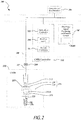
- FIGURE 2 is a diagram of a coordinate measurement system 200, and an automatically connectable and interchangeable CRS optical probe system 215. That is, the CRS optical probe system 215 may be automatically interchanged with other types of CMM probes.
- a CRS optical probe system may also be referred to simply as a CRS optical probe herein.
- reference numbers having similar suffixes e.g. reference number 1XX and 2XX having the suffix XX
- reference numbers having similar suffixes may refer to generally analogous elements, such that operation of element 2XX may be generally understood by one of ordinary skill in the art with limited description, based on analogy to a previous description of analogous element 1XX, and so on.
- various elements may have different implementations in different embodiments, as will be apparent to one of ordinary skill in the art, and are not limited to be identical.
- the coordinate measurement system 200 includes a coordinate measurement machine controller 202, a computer and user interface 206, a probe signal processing and control circuit 207, and a coordinate measurement machine 210.
- the controller 202 includes a probe head controller 203, a position latch 204 and a motion controller 205.
- the CRS optical probe 215 includes an auto exchange joint element 236, and is connected to the coordinate measurement machine 210 through a mating joint element in the probe autojoint connection 230 (also referred to as an auto exchange joint connection).
- the coordinate measurement machine 210 communicates with all of the other components through a data transfer line 201 (e.g. a bus), which is connected by a connector 208 (e.g. a "micro-D" type connector) to a probe head cable 211 which provides signals to and from the CRS optical probe 215.
- the coordinate measurement machine 210 is controlled by the coordinate measurement machine controller 202, while the CRS optical probe 215 exchanges data with, and is controlled by, the probe signal processing and control circuit 207 (e.g. in one embodiment, a probe signal processing and control circuit including measurement signal processing and control elements 260B, as outlined above with reference to the element 160B in FIGURE 1 ).
- the user may control all of the components through the computer and user interface 206.
- the CRS optical probe 215 includes a probe electronics 275 which includes a light source and wavelength detector portion 260A (e.g. in one embodiment, a light source and wavelength detector as outlined above with reference to the element 160A, in FIGURE 1 ), and an optical pen 220, which directs a measurement beam 296 toward a measurement surface 290.
- the measurement surface 290 may comprise an internal surface of a threaded hole. Such surfaces have been difficult or impossible to measure completely and reliably with known CMM probes (e.g. a touch probe).
- a CRS optical probe such as that disclosed herein is able to scan and measure such surfaces with improved completeness, accuracy and versatility.
- data related to the optical pen and/or interchangeable optics element may be stored externally to the CRS optical probe 215 (e.g. in the probe signal processing and control circuit 207.)
- portions of such data may be stored or otherwise encoded within portions of the CRS optical probe 215.
- FIGURES 3A and 3B are diagrams schematically illustrating certain components of the coordinate measurement machine 210 and a CRS optical probe 215', which is similar to the CRS optical probe 215 of FIGURE 2 .
- FIGURE 3A is a front view
- FIGURE 3B is a view from a different angle of the coordinate measurement machine 210 and the CRS optical probe 215'.
- the coordinate measurement machine 210 includes a probe head 213.
- the probe head 213 receives and transmits probe signals through the probe head cable 211.
- the probe head 213 is secured to a coordinate measurement machine quill 217.
- the probe head 213 is connected to the probe 215' at a probe autojoint connection 230 which will be described in more detail below with respect to FIGURE 6 .
- the probe head 213 in some embodiments rotates in 360 degrees in a horizontal plane and contains a type of U-joint.
- the probe autojoint connection 230 is an electro-mechanical connection that fastens the probe head 213 rigidly and mechanically to the CRS optical probe 215', in a way such that it can be disconnected from one probe and attached to another.
- the probe autojoint connection 230 may include first and second mating auto exchange joint elements 234 and 236, wherein the first auto exchange joint element 234 is mounted to the probe head 213, and the second mating auto exchange joint element (236) is mounted to the CRS optical probe 215'.
- the probe autojoint connection 230 has mating electrical contacts or connections 235 so that when a probe is attached, the contacts automatically engage and make electrical connections.
- this connection method can cause the system to have a relatively high amount of signal noise, which as will be described in more detail below makes it advantageous to use certain configurations and methods which can function effectively in a relatively noisy environment.
- the CRS optical probe 215' receives its power and control signals through the autojoint connection 230.
- the signals passed to the CRS optical probe 215' through the autojoint connection 230 are passed through connections 235 as will be described in more detail below with respect to FIGURE 6 .
- the CRS optical probe 215' includes auto exchange joint element 236 and a probe assembly 216 that is mounted to the auto exchange joint element 236, for automatic connection to the CMM through the probe autojoint connection 230.
- the probe 215' may also include a protective cover or housing 269 (schematically illustrated).
- the probe assembly 216 comprises an optical pen 220, and probe electronics 275 which may comprise an electrically powered light source 264 and a wavelength detector 262, all supported by various structural members.
- the structural members extend from a base 218 that is attached to the auto exchange joint element 236.
- the optical pen 220 (analogous to the optical pen 120) may include a fiber optic connector 209, and a confocal optical path including an aperture 295 and chromatically dispersive optics portion 250, which outputs a measurement beam 296.
- the optical pen 220 may include a repeatable fast exchange mount 285 which allows replacement of the chromatically dispersive optics portion 250, as described in greater detail below.
- the electrically powered light source 264 may work in conjunction with known circuits (e.g. as found in commercial chromatic ranging systems) included in a probe power and signal control circuit portion 276 which is included in probe electronics 275, and which receives electrical power transmitted through the auto exchange joint element.
- the probe electronics 275 includes a serializer 277S that allows various data signals to be serialized and communicated through the autojoint connection 230 using relatively few wires to a deserializer (included, for example, in the probe signal processing and control circuit 207), as described in greater detail below.
- the serializer 277S is included on the probe power and signal control circuit portion 276.
- the serializer 277S may be included with the CRS wavelength detector 262, since much of the serialized data to be transmitted is measurement spectral profile data that originates in the CRS wavelength detector 262. More generally, the serializer 277S may be located at any desired location in the probe electronics 275 that provides satisfactory noise and crosstalk characteristics.
- the light source 264 generates light originating in the CRS optical probe assembly, the light comprising an input spectral profile of wavelengths routed to the optical pen 220 through the fiber optic cable 212.
- the CRS wavelength detector 262 may comprise known circuits (e.g. as found in commercial chromatic ranging systems) that work in conjunction with a spectrometer arrangement 262' and detector array 263 comprising a plurality of pixels distributed along a measurement axis of the CRS wavelength detector, the plurality of pixels receiving respective wavelengths reflected into the confocal optical path from the target surface and providing output spectral profile data.
- a configuration such as that outlined above which generates and processes the light used for measurement entirely within the CRS optical probe assembly allows the CRS optical probe assembly to be self-contained and automatically exchangeable.
- a CRS optical probe system does not require or include an optical fiber connection from the CRS optical probe assembly to an outside element through the auto joint connector, or along any other makeshift path in parallel with the auto joint connector.
- such a CRS optical probe assembly does not connect to or include an optical fiber that extends outside of the CRS optical probe assembly.
- the CRS optical probe assembly is configured such that the optical pen is mounted at a distal end of the CRS optical probe assembly.
- the CRS optical probe assembly 215' includes the base portion 218, a wavelength detector mounting portion 219A coupled to the base portion 218, and an optical pen mounting portion 219B coupled to the base portion and carrying the optical pen without carrying the wavelength detector, which may isolate heat and mass-related deflection and vibration away from the optical pen.
- one or both of the mounting portions 219A and 219B may comprise a hollow structural tube (e.g. a carbon fiber tube) that extends away from the base portion and toward the distal end of the CRS optical probe assembly.
- the center of mass of the optical pen 220 is located proximate to an axis defined by the center of mass CMPA of the rest of the CRS optical probe 215' and the center axis CAJ of the probe autojoint connection 230.
- Such a configuration may provide for smoother operation of the probe head 213 as it is utilized to move the CRS optical probe 215' (e.g. avoiding unnecessary additional torque, vibration, deflection, etc.)
- the optical pen 220 may also be mounted relative to the probe autojoint connection 230 such that the central axis CAOP (e.g. a reference axis for measurements) of the optical pen 220 is coaxial with the central axis CAJ of the auto exchange joint 230.
- CAOP central axis CAOP
- the optical pen 220 when the CMM rotates the probe autojoint connection 230 around its axis, the optical pen 220 may also be rotated around its axis with no lateral movement of the measurement reference axis in a X-Y plane.
- Such a configuration may provide certain advantages (e.g. being mechanically more stable, simplifying the calculation of the location of the measurements taken with the optical pen 220 relative to the positioning by the CMM, etc.)
- FIGURES 4A and 4B are diagrams illustrating components of the optical pen 220 of FIGURES 3A and 3B , for an embodiment that includes an exemplary repeatable fast exchange mount 285.
- the optical pen 220 includes a base member 282 and an interchangeable optics element 280.
- the interchangeable optics element 280 includes a front plate 286, tube 231, and chromatically dispersive optical portion 250.
- the base member 282 includes a base housing 282A which includes a surface which serves as a first mating half 285A of the repeatable fast exchange mount 285, and the front plate 286 has a corresponding surface which serves as a second mating half 285B of the repeatable fast exchange mount 285.
- the second mating half 285B of the repeatable fast exchange mount 285 is forced against the first mating half 285A by a holding force arrangement comprising permanent magnets 285C mounted in one or both of the first and second mating halves 285A or 285B.
- the holding force arrangement may comprise known means such as spring-loaded mechanical detents, or the like.
- the optical pen may include a collar 232 or the like, which may be guided under program control such that it is inserted between the arms of a mating fork included on a probe rack within the motion volume of a CMM.
- the CMM may then move the CRS optical probe 215' such that the arms of the fork bear on the collar 232 and force the mating halves of the repeatable fast exchange mount 285 apart, leaving the interchangeable optics element 280 hanging in the probe rack.
- the interchangeable optics element 280 may be mounted back to the base member 282 by the reverse of these operations.
- the interchangeable optics element 280 will separate from the base member 282, rather than being damaged.
- the repeatable fast exchange mount 285 may comprise three spheres or balls 285D which are fixed in the first mating half 285A in a first triangular pattern (e.g. an equilateral triangle), and a three radially oriented V-grooves 285E which are fixed in the second mating half 285B in a mating pattern.
- a first triangular pattern e.g. an equilateral triangle
- a three radially oriented V-grooves 285E which are fixed in the second mating half 285B in a mating pattern.
- Such an embodiment of the repeatable fast exchange mount 285 allows the interchangeable optics element 280 to be mounted with the laterally oriented measurement beam 296 facing in any of three different orientations spaced 120 degrees apart.
- Such an embodiment is exemplary only, and not limiting.
- Various other repeatable fast exchange mounting configurations may be used, provided that adequate mounting repeatability is provided, as is generally known in the art.
- the interchangeable optics element 280 includes the chromatically dispersive optical portion 250 (e.g. analogous to the chromatically dispersive optical portion 150 described above with respect to FIGURE 1 .)
- the base member 282 includes the end of an optical fiber 212 that is connected to the LED light source 264 and to the spectrometer arrangement 262' through a fiber connector 261.
- the end of optical fiber may be located proximate to a confocal aperture 295 that is fixed relative to the first mating half 285A of the repeatable fast exchange mount 285, which may generally surround the confocal aperture 295.
- the end of the optical fiber provides the confocal aperture.
- the confocal aperture 295 is provided by a thin aperture that is bonded in place proximate to or abutting the end of the optical fiber (e.g. on a holder or connector that holds the optical fiber).
- the base member 282 includes an optical fiber end positioning arrangement 283 comprising an optical fiber holding element (e.g. a fiber optic connector that mates with the connector 209, in this embodiment) that is fixed (e.g. bonded) in the base member 282 proximate to the first mating half 285A of the repeatable fast exchange mount 285.
- the optical fiber end positioning arrangement 283 may comprise an optical fiber holding element that holds the optical fiber (e.g.
- the confocal aperture may be separately fixed to the base member 282 and the end of the optical fiber may be fixed proximate to that confocal aperture by a suitable optical fiber end positioning element, if desired, as described in greater detail below.
- the interchangeable optics element 280 receives measurement light from, and returns measurement light to, the confocal aperture 295, and provides axial chromatic dispersion of the measurement light over a respective measuring range along a measuring axis.
- the chromatically dispersive optical portion 250 may also include a reflective element 294, which directs the measurement beam laterally to the axis of the optical pen 220 (e.g. laterally relative to the axis of the tube 231).
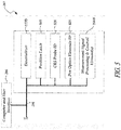
- FIGURE 5 is a block diagram of one embodiment of the computer and user interface 206 and the probe signal processing and control circuit 207 of FIGURE 2 .
- the probe signal processing and control circuit 207 may include a deserializer 277D, a position latch 515, a CRS optical probe ID 520 and an optical pen ID 525.
- the components of the probe signal processing and control circuit 207 are coupled to one another and to the computer and user interface 206 by the data transfer line 201.
- the deserializer 277D may work in conjunction with the serializer 277S shown in FIGURE 3A , to allow various data signals to be serialized and communicated through the autojoint connection 230 using relatively few wires.
- the serializer 277S and a deserializer 277D are related to the utilization of certain low voltage differential signaling (LVDS) that may be used in some embodiments, as will be described in more detail below with respect to FIGURE 7 .
- LVDS low voltage differential signaling
- a synchronization signal is provided between a serializer and a deserializer, in order to ensure that they are synchronized.
- clock signals are provided until the deserializer is finished, at which point the synchronization signal is switched, after which the relevant data signals are provided on the signal lines (as opposed to the previous clock signals.)
- the position latch 515 relates to an XYZ latch signal that will be described in more detail below with respect to FIGURE 7 .
- an XYZ latch signal is provided for synchronizing the measurement positioning of the CRS optical probe with the measurement positioning of the coordinate measurement machine controller 202.
- the position latch 515 communicates with the position latch 204 in the coordinate measurement machine controller 202 in order to ensure that the coordinates of the coordinate measurement machine 210 are properly synchronized.
- the position latch 515 and the position latch 204 combine to ensure the accuracy of the overall derived measurements, such that the CMM machine coordinates (which reflect the position of the CRS optical probe during a particular measurement) are properly combined with the CRS optical probe measurements (which are relative to the CRS optical probe position).
- the CRS optical probe ID 520 is utilized for determining the identification of the CRS optical probe 215' (e.g. by reading and processing an identification signal derived from an identifying element included in the CRS optical probe 215'), and the optics elements ID 525 is utilized for determining the identification of the interchangeable optics element 280 (e.g. by reading and processing an identification signal derived from an identifying element included in the interchangeable optics element 280).
- the proper identification of the CRS optical probe 215' and the interchangeable optics element 280 allow proper configuration and calibration data to be utilized in order to ensure accurate operations and resulting measurements from the CRS optical probe 215' and interchangeable optics element 280.
- FIGURE 6 is a diagram illustrating a cross section of the probe data cable 211 of FIGURE 2 .
- the probe data cable 211 includes a sheath 605, sealing tape layers 610, an electrical outer shield layer 615 and a coaxial cable 620 including a central conductor "1" and an inner shield layer 625. Additional conductors 2 through 14 are shown as surrounding the coaxial cable 620, in accordance with a conventional RenishawTM configuration, as will be described in more detail below with respect to FIGURE 7 .
- FIGURE 7 is a table 700 outlining one exemplary connection and/or signal scheme usable with the probe data cable 211 of FIGURE 6 and /or the autojoint connection 230 shown in FIGURES 3A and 3B .
- the connection numbers in the "Wire #" column indicate the wire number of the cable 211 that is connected to an auto joint pin (e.g. one standard RenishawTM autojoint connection configuration), unless otherwise indicated.
- power and signal ground connections may be provided on the various wires and connected auto joint pins.
- LVDS low voltage differential signaling
- SERDES+, SERDES- and SERDES block/sync may be provided on the various wires and connected auto joint pins.
- a plurality of wires may be used in combination to provide power to the CRS CMM probe, in order to meet certain standard autojoint and/or CMM controller design requirements (e.g. not providing more than 300 mA through any single conductor). For example, using two wires at 12 V, 300 mA each provides the capability of delivering 7.2 watts within standard autojoint and/or CMM controller specifications.)
- the various signals may be routed on any suitable wire and/or autojoint pin.
- the serializer signals SERDES+, SERDES- are carried on lines/pins that connect the deserializer 277D and serializer 277S. Experiment and/or analysis may be used to select and/or verify the connections that provide reliable signal transmission.
- a position D0 is designated as being for the detector pixel clock.
- a position D1 is designated as being for the profile start signal for the spectral profile measurement data.
- a position D2 is designated as being for the spectrometer ready signal.
- the position D3 is designated as being for the XYZ latch signal (e.g. as described in more detail above with respect to the position latch 515 of FIGURE 5 .)
- a position D4 is designated as being for a detector temperature alarm.
- the position D5 is designated as being for a spectrometer temperature alarm.
- the positions D6-D9 are not yet designated and thus are not specifically assigned in this embodiment.
- the fastest available digital signal may be utilized (e.g. a detector pixel clock signal at several MHz.)
- the serializer may then sample the digital signals at a relatively fast rate (e.g. two times the detector pixel clock rate.)
- the LVDS serializer may sample up to 10 digital signals per sample cycle.
- the serializer may then transmit the combined signals at a much faster rate (e.g. 2 times the detector pixel clock rate times ⁇ 10 digital signals + 2 synchronization bits>), which may provide a bit rate of more than 100MHz, in some embodiments.
- LVDS serializer low voltage differential signaling serializer
- the standard autojoint connector only provides a limited number of connections (e.g. 13 pins.)
- a standard CRS system may utilize significantly more conductors such as between the controller and the spectrometer (e.g. 24 conductors.) The conductor count can be reduced in part by avoiding non-crucial signals.
- the LVDS serializer technique allows more signals to be provided to the controller board using only two signal lines, as described above with respect to FIGURE 7 .
- Such LVDS serialization techniques may provide at least three or more distinct signals over two connections/conductors through the auto exchange joint element, and in some embodiments up to 10 digital signals or types of information using only two conductors through the auto exchange joint element.
- the signals are made to be robust, in that the differential signals ignore common mode noise.
- the technique may be implemented with low power (e.g. in one specific example embodiment the signals may be sent at +/- 500mV with a 1V offset), which may be important in a CMM probe application.
- a high speed can be achieved (e.g. a range of 100 MHz to GHz operation.)
- the signals may travel over relatively long wires (e.g.
- the LVDS serialization techniques may be implemented using a SN65LV1023 serializer and SN67LV1224 deserializer from Texas Instrument of Dallas, Texas, USA.
- the signaling protocol outlined above, or other known LVDS signaling protocols, may be used.
- an auto-connecting free-space fiber coupling is provided in which the light used in the CRS optical probe assembly propagates in free space through optical elements mounted in a fixed relationship in the free-space fiber coupling.
- a group of components in a light source and wavelength detector portion 160A e.g.
- the group of components in the light source and wavelength detector portion 160A may be located with the measurement signal processing and control circuit 160B. In one implementation, the group of components in the light source and wavelength detector portion 160A may be located with a CMM controller (see coordinate measurement machine (CMM) controller 202 of Figure 2 ).
- CMM coordinate measurement machine
- Physical contact fiber couplers can easily be damaged with repeated mating cycles due to the contamination of fiber surfaces. Even a small amount of dust may lead to significant throughput loss. Thus, physical contact fiber couplers may provide for only a limited number of operation cycles.
- the use of an auto-connecting free-space fiber coupling provides for an automatically interchangeable CRS optical probe system configured for a high number of automated mating cycles and reduced risk of contamination.
- FIGURE 8 is a diagram of a coordinate measurement system 800, and an automatically connectable and interchangeable CRS optical probe system 815. That is, the CRS optical probe system 815 may be automatically interchanged with other types of CMM probes.
- the coordinate measurement system 800 includes a coordinate measurement machine controller 802, a computer and user interface 806, a probe signal processing and control circuit 807, and a coordinate measurement machine 810.
- the controller 802 includes a probe head controller 803, a position latch 804 and a motion controller 805.
- the CRS optical probe 815 includes a probe assembly 816, an auto exchange joint element 836, and is connected to the coordinate measurement machine 810 through a mating joint element in the probe autojoint connection 830 (also referred to as an auto exchange joint connection), and through a free-space fiber coupling 870.
- the coordinate measurement machine 810 communicates with other components through a data transfer line 801 (e.g. a bus), which is connected by a connector 808 (e.g. a "micro-D" type connector) to a probe head cable 811 which provides signals to and from the CRS optical probe 815.
- a data transfer line 801 e.g. a bus
- the data transfer line 801 may also be connected by a connector 808' to a cable 811' (e.g., as will be described in more detail below with respect to FIGURE 9 ) which may additionally or alternatively provide power and/or communications to and from the CRS optical probe 815.
- the coordinate measurement machine 810 is controlled by the coordinate measurement machine controller 802, while the CRS optical probe 815 exchanges data with, and is controlled by, the probe signal processing and control circuit 807 (e.g. in one embodiment, a probe signal processing and control circuit including wavelength detector and light source elements 860A and detector measurement signal processing and control elements 860B, as outlined above with reference to the elements 160A and 160B in FIGURE 1 ).
- the probe signal processing and control circuit 807 e.g. in one embodiment, a probe signal processing and control circuit including wavelength detector and light source elements 860A and detector measurement signal processing and control elements 860B, as outlined above with reference to the elements 160A and 160B in FIGURE 1 .
- the user may control all of the components through the computer and user interface 806.
- the wavelength detector and light source elements 860A and the detector measurement and control elements 860B may be included in the CMM controller 802 instead of the probe signal processing and control circuit 807, as indicated by the dashed boxes in FIGURE 8 .
- the CRS optical probe 815 includes a free-space fiber coupling 870, and an optical pen 820, which directs a measurement beam 896 toward a measurement surface 890.
- the measurement surface 890 may comprise an internal surface of a threaded hole, such as discussed above with reference to FIGURE 2 .
- FIGURE 9 is a diagram schematically illustrating certain components of the coordinate measurement machine 810 and a CRS optical probe 815 of FIGURE 8 .
- the coordinate measurement machine 810 includes a probe head 813 (only a connector portion of which is illustrated in FIGURE 9 ).
- the probe head 813 receives and transmits probe signals through the probe head cable 811, and may be similar to the probe head 213 of FIGURE 2 .
- the probe head 813 is connected to the probe 815 at a probe autojoint connection 830.
- the probe head cable 811 may be similar to the probe head cable 211 described above with respect to FIGURES 2 , 3A , 3B and 6 .
- the probe head 813 in some embodiments rotates in 360 degrees in a horizontal plane and contains a type of U-joint.
- the probe autojoint connection 830 is an electro-mechanical connection that fastens the probe head 813 rigidly and mechanically to the CRS optical probe 815, in a way such that it can be disconnected from one probe and attached to another.
- the probe autojoint connection 830 may include first and second mating auto exchange joint elements 834 and 836, wherein the first auto exchange joint element 834 is mounted to the probe head 813, and the second mating auto exchange joint element 836 is mounted to the CRS optical probe 815.
- the probe autojoint connection 830 has mating electrical contacts or connections 835 so that when a probe is attached, the contacts automatically engage and make electrical connections.
- an electric auto connection 830' may also or alternatively be utilized for providing certain power and/or communications to and from the CRS optical probe 815.
- the electric auto connection 830' may be an electro-mechanical connection that couples a cable 811' to the CRS optical probe 815, in a way such that the cable 811' can be disconnected from one probe and attached to another.
- the electric auto connection 830' may include first and second mating auto exchange elements 834' and 836', wherein the first auto exchange element 834' is mounted to the probe head 813, and the second mating auto exchange element 836' is mounted to the CRS optical probe 815.
- the electric auto connection 830 has mating electrical contacts or connections so that when a probe is attached, the contacts automatically engage and make electrical connections.
- the electric auto connection 830 may be a kinematic coupling and/or may include magnets on either or both of the auto exchange elements 834' or 836' for holding the connection together.
- the CRS optical probe 815 receives its power and control signals through the autojoint connection 830 and/or through the electric auto connection 830'.
- the signals passed to the CRS optical probe 815 through the autojoint connection 830 and/or through the electric auto connection 830' may be passed via connections, such as one or more of the connections 235 of FIGURE 6 or other types of connections.
- the CRS optical probe 815 comprises a pen assembly 816 including an optical pen 820.
- one particular advantage of the utilization of the electric auto connection 830' is in relation to the issue noted above for which a standard autojoint connection 830 may have a limited number of wired connections available, and for which more connections may be desirable/utilized for the CRS optical probe 815 (e.g., as may be provided through the electric auto connection 830').
- certain CRS optical probes 815 may also have additional features/capabilities that may require additional power and/or communication signals that can also be provided through the electric auto connection 830'.
- the CRS optical probe may include a rotational element (e.g., that is utilized to rotate an optics element of the optical pen 820 and the corresponding direction of a measurement beam 896 as illustrated in FIGURE 8 ), and for which the electric auto connection 830' may be utilized to provide power and/or communication signals for powering and/or controlling the rotational element.
- a rotational element e.g., that is utilized to rotate an optics element of the optical pen 820 and the corresponding direction of a measurement beam 896 as illustrated in FIGURE 8
- the electric auto connection 830' may be utilized to provide power and/or communication signals for powering and/or controlling the rotational element.
- a CRS optical probe may include a rotary element that rotates an optics element, and for which in various implementations the rotary element may include components such as bearings, gears and/or a motor for driving the rotation.
- the power and/or control signals for the rotary configuration may be provided through the electric auto connection 830'.
- the system 800 includes a free-space fiber coupling 870.
- the free-space fiber coupling may be a kinematic coupling.
- a first coupling element 871 of the free-space fiber coupling 870 is fastened to the probe head 813 via a first clamp 873, and a second coupling element 872 of the free-space fiber coupling 870 is fastened to the CRS optical probe 815 by a second clamp 874.
- first and second clamps 873, 874 may be a floating clamp or flexible bracket to allow some freedom of movement for one or more of the first coupling element 871 and the second coupling element 872, which may facilitate alignment and snapping together of the first and second coupling elements 871, 872 of the free-space fiber coupling 870, for example during an automated coupling process.
- first and second auto exchange elements 834', 836' of the electric auto connection 830' may similarly be aligned and couple together, and the first and second mating auto exchange joint elements 834, 836 of the probe autojoint connection 830 may similarly be aligned and couple together.
- the respective elements may be pulled apart/decoupled to allow the CRS optical probe 815 to be removed from the probe head 813.
- the CRS optical probe 815 (or a different CRS optical probe) may be coupled to the probe head 813 or may be coupled to a different probe head.
- the probe autojoint connection 830, electric auto connection 830' and/or free-space fiber coupling 870 may each have respective coupling planes approximately aligned with one another which may have certain advantages (e.g., as related to facilitating the coupling/decoupling process, such as by simplifying/improving the overall mechanics of the coupling/decoupling, etc.)
- the second auto exchange elements 836' and/or other elements of the CRS optical probe may have certain portions that are configured (e.g., extended, indented, such as having grooves in the side, etc.) for facilitating being grasped or otherwise contacted and moved by a movement mechanism (e.g., a robot arm with engaging and/or grasping elements at the end) for engaging and moving the CRS optical probe 815 as part of an automated coupling or decoupling process to or from the probe head 813.
- a movement mechanism e.g., a robot arm with engaging and/or grasping elements at the end
- the first coupling element 871 of the free-space fiber coupling 870 is connected to a first fiber optic cable 812', which is coupled to the wavelength detector and light source elements 860A (see FIGURE 8 ).
- the second coupling element 872 is connected to a second fiber optic cable 812", which is coupled to the optical pen 820.
- the free-space fiber coupling 870 may comprise FC/APC (angle polished connector, e.g., polishing the fiber at an 8 or 9 degree angle) fiber ferrule connectors having angled connections (e.g., 4 degree angles), which may facilitate reducing back reflection.
- FC/APC angle polished connector, e.g., polishing the fiber at an 8 or 9 degree angle
- fiber ferrule connectors having angled connections (e.g., 4 degree angles), which may facilitate reducing back reflection.
- the optical pen 820 (analogous to the optical pen 120) may include a fiber optic connector 809, and a confocal optical path including an aperture 895 and chromatically dispersive optics portion 850, which outputs a measurement beam 896.
- the optical pen 820 may include a repeatable fast exchange mount 885, which allows replacement of the chromatically dispersive optics portion 850, as described in greater detail in the description of FIGURES 4A and 4B .
- FIGURE 10 is a block diagram illustrating the optical connection paths of an example embodiment of the system 800 of FIGURE 8 .
- the optical pen 820 includes a fiber optic connector 809, and an optics element 880, which may be interchangeable.
- the fiber optic connector 809 may be attached to the end of a housing 831.
- the fiber optic connector 809 may be mounted to a fixed mount and the optics element 880 may be mounted to a rotational element (e.g., in a configuration similar to the embodiment of the 240' patent wherein an interchangeable optics element is rotated by a rotary element, or in any other configuration with a rotational element for rotating the optics element).
- the fiber optic connector 809 receives a first end of an in/out optical fiber (not shown in detail) through a fiber optic cable 812" which encases it.
- the in/out optical fiber outputs source light and receives reflected light through a fiber aperture.
- the source light and reflected light are used to take measurements, such as discussed above in more detail in the description of FIGURE 1 .
- a second end of fiber optic cable 812" is received in fiber optic connector 809" of the second coupling element 872 of free-space fiber coupling 870.
- a first end of fiber optic cable 812' is received in fiber optic connector 809' of the first coupling element 871 of free-space fiber coupling 870.
- Source light and reflected light are transmitted in free space within the free-space fiber coupling 870.
- a second end of the fiber optic cable 812' is coupled to a fiber coupler 861 of the electronics portion 860, which also includes a wavelength detector 862, a light source 864, a signal processor 866 and a memory portion 868.
- the fiber coupler 861, wavelength detector 862 and light source 864 may be included as part of a wavelength detector and light source elements 860A, and the signal processor 866 and memory portion 868 may be included as part of a detector measurement signal processing and control elements 860B (e.g., similar to the example configurations of FIGURES 1 and 8 ).
- the wavelength detector 862 includes a spectrometer or spectrograph arrangement wherein a dispersive optics portion (e.g. a grating) receives the reflected light through the optical fiber cable 812' and transmits the resulting spectral intensity profile, for example to a detector array (see detector array 163 of FIGURE 1 ).
- the wavelength detector 862 may also include related signal processing (e.g. provided by the signal processor 866, in some embodiments) that removes or compensates certain detector-related error components from the profile data.
- related signal processing e.g. provided by the signal processor 866, in some embodiments
- certain aspects of the wavelength detector 862 and the signal processor 866 may be merged and/or indistinguishable in some embodiments.
- the white light source 864 which is controlled by the signal processor 866, is coupled through the optical coupler 861 (e.g. a 2x1 optical coupler) to the fiber cable 812'.
- the optical coupler 861 e.g. a 2x1 optical coupler
- the light travels through free-space fiber coupling 870 and the optical pen 820, which produces longitudinal chromatic aberration so that its focal length changes with the wavelength of the light.
- the wavelength of light that is most efficiently transmitted back through the fiber is the wavelength that is in focus on the surface 890 at the position Z (see FIGURES 1 and 8 ).
- the reflected wavelength-dependent light intensity then passes through free-space fiber coupling 870 and the fiber coupler 861 again so that a portion of the light (e.g., approximately 25% of the light for certain 1x2 optical couplers in such configurations) is directed to the wavelength detector 862, which may receive a spectral intensity profile distributed over an array of pixels along a measurement axis of the detector array (see detector array 163 of FIGURE 1 ), and operate to provide corresponding profile data as described in more detail in the incorporated references and above in the discussion of FIGURE 1 .
- FIGURE 11 is a diagram schematically illustrating certain components of the free-space fiber coupling 870 of FIGURE 8 .
- the second end of fiber optic cable 812" is received in fiber optic connector 809" of the second coupling element 872 of free-space fiber coupling 870.
- the first end of fiber optic cable 812' is received in fiber optic connector 809' of the first coupling element 871 of free-space fiber coupling 870.
- the free-space fiber coupling 870 couples and decouples at a kinematic coupling plane 878 of a kinematic mount 879.
- the first coupling element 871 on the source side has a lens system 850' including chromatic aberration corrected lenses to transmit the visible light spectrum.
- the lens system 850' includes a collimating lens 852' and a focusing lens 853'.
- the collimating lens 852' collects the output of the fiber of the fiber cable 812' secured in the fiber optic connector 809', and collimates the light into the focusing lens 853', which focuses the collimated light into the fiber of the fiber optic cable 812" secured in the fiber optic connector 809".
- the lens system 850' protects the fiber of the fiber cable 812', for example, by preventing dirt and dust to the fiber core.
- the second coupling element 872 on the sensor side has a protective glass window 858', which protects the fiber of the fiber cable 812".
- the light transmitted by the focusing lens 853' passes through the protective glass window 858', and enters the fiber of fiber cable 812".
- a lens may act as a collimating lens for light traveling in a first direction, and act as a focusing lens for light traveling in a second direction.
- reflected light returns via the fiber of fiber cable 812" through the protective glass window 858' to the focusing lens 853', which acts as a collimating lens with respect to the reflected light, and collimates the reflected light into collimating lens 852'.
- Collimating lens 852' acts as a focusing lens for the reflected light, and focuses the reflected light into the fiber of the fiber cable 812'.
- the fiber optic connectors 809', 809" as illustrated are FC/APC fiber ferrule connectors configured to secure the fiber of the fiber optic cables 812', 812" at an angle 857' with respect to an axis of the lens system 850', for example, at a 4 degree angle.
- the configuration facilitates reducing back reflection in the system 800.
- the kinematic coupling plane 878 of the kinematic mount 879 is positioned approximately at the focusing lens 853', or between the focusing lens 853' and the fiber of the fiber optic cable 812".
- an end plane 878' of the first coupling element 871 and/or of the lens system 850' may be between the focusing lens 853' and the fiber of the fiber optic cable 812" (e.g., for which the end plane 878' may be parallel to the kinematic coupling plane 878 and be located at an end point or surface of the first coupling element 871 and/or lens system 850' that is closest to the fiber of the fiber optic cable 812").
- positioning the coupling plane 878 and/or end plane 878' between the focusing lens 853' and the fiber of the optic cable 812" provides a kinematic coupling which is less sensitive to tilt and which has a low Z position dependence.
- the lens system 850' is positioned in the first coupling element 871 on the source or CMM (see CMM 810) side, and the decoupling plane 878 is positioned at the focusing lens 853' or between the focusing lens 853' and the fiber of the sensor or CRS optical probe (see CRS optical probe 815) fiber cable 812".
- the decoupling plane 878 is positioned at the focusing lens 853' or between the focusing lens 853' and the fiber of the sensor or CRS optical probe (see CRS optical probe 815) fiber cable 812".
- the lens system 850' may instead be positioned in the second coupling element 872 on the sensor or CRS optical probe 815 side, with the decoupling plane 878 and/or end plane 878' positioned between the lens system 850' and the fiber of the source or CMM 810 side fiber cable 812'.
- the configuration may be reversed (e.g., for which the implementations of FIGURES 8 and 9 may be representative of including the configuration in the orientations as illustrated in FIGURES 10 , 11 and 16 , or alternatively may include the configuration in a reversed orientation, with the lens system 850' and corresponding components on the side with the fiber optic cable 812", etc.
- FIGURES 12A and 12B are diagrams illustrating certain details of an exemplary kinematic mount 879.
- FIGURE 12A shows a sensor-side coupling 879" of the kinematic mount 879
- FIGURE 12B shows a source-side coupling 879' of the kinematic mount 879.
- the sensor-side coupling 879" has three ball bearings 891 which mate with three corresponding v-grooves 892 of the source-side coupling 879'.
- Three corresponding magnets of the source-side coupling 879' are located proximate to and radially inward from each of the v-grooves 892, and act to magnetically couple (i.e., as part of the kinematic coupling) to the surface of the sensor-side coupling 879" that the ball bearings 891 are located on (i.e., magnetically coupling to the surface at locations just radially inward from each of the ball bearings 891 in the illustrated configuration).
- the ball bearings 891 and the v-grooves 892 are positioned so as to properly align the source-side coupling 879' and the sensor-side coupling 879" when the kinematic mount 879 is coupled together (e.g., the spacing of the ball bearings 891 and the v-grooves 892 may be non-uniform so that only one coupling position is possible).
- other types of kinematic mounts may be employed (e.g., cone mounts).
- FIGURE 13 illustrates one possible configuration of a lens system 1350 of a fiber coupling 1370 (e.g., as representative of a configuration of certain prior systems).
- the coupling plane 1378 of the kinematic mount 1379 is positioned between the collimating lens 1352 and the focusing lens 1353 (e.g., as may be representative of a conventional location of a coupling plane in a fiber coupling configuration, with a lens and a fiber on each side of the coupling plane).
- the configuration of FIGURE 13 is noted to have a high throughput sensitivity to tilt.
- FIGURES 14 and 15 illustrate exemplary configurations of lens systems 850' of the free-space fiber coupling 870 of FIGURE 8 .
- the coupling plane 878 of the kinematic mount 879 is positioned between the focusing lens 853' and the fiber of the fiber cable 812".
- the location of the coupling plane 878 may also or alternatively be representative of a location of an end plane 878' of the first coupling element 871 and/or of the lens system 850' (e.g., of FIGURE 11 ).
- Such configurations thus have both lenses 852' and 853' on one side of the coupling plane 878 and/or end plane 878' (e.g., the side with the fiber of the fiber cable 812'), and no lens(es) on the other side of the coupling plane 878 and/or end plane 878' (e.g., the side with the fiber of the fiber cable 812").
- Such a configuration has a lower/improved throughput sensitivity to tilt, as compared to the configuration of FIGURE 13 , and has low throughput sensitivity to Z-position dependence and has a moderate sensitivity to lateral XY position tolerance. The tradeoff in reduced sensitivity to tilt vs.
- FIGURE 15 differs from FIGURE 14 in that the configuration of FIGURE 15 includes a protective glass 858' positioned between the focusing lens 853' and the fiber of the fiber cable 812".
- the protective glass window 858' may have an antireflective coating.
- FIGURE 16 illustrates an alignment mechanism of a kinematic mount of an exemplary free-space fiber coupling of the system of FIGURE 8 .
- one or more set screws 899 may be adjusted to align the fibers of the fiber cables 812', 812" relative to the lenses 852', 853'.
- Other alignment mechanisms may be employed.
- the kinematic mount should be a highly repeatable and automatable coupling mechanism for the free-space fiber coupling 870.
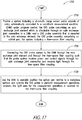
- FIGURE 17 is a flow diagram illustrating one exemplary embodiment of a routine 1700 for providing and operating an automatically interchangeable CRS optical probe embodiment as disclosed herein.
- a system includes a CRS optical probe that is capable of being automatically connected to a CMM under program control.
- the CRS optical probe includes an auto exchange joint element which is attachable through a standard auto exchange joint connection to a CMM, and a CRS optical probe assembly that is mounted to the auto exchange joint element for automatic connection to the CMM through the auto exchange joint element.
- the system includes a free-space fiber coupling to provide an optical path for the light used by the CRS optical probe assembly.
- the CRS optical probe assembly includes an optical pen.
- the optical pen comprises a confocal optical path including a chromatically dispersive optics portion, the optical pen configured to focus different wavelengths at different distances along a measurement axis proximate to a workpiece surface to be measured.
- the light transmitted via the free-space fiber coupling comprises an input spectral profile of wavelengths routed to the optical pen.
- the CRS optical probe is connected to a CMM through the auto exchange joint element and through the free-space fiber coupling.
- Certain power and control signals may be provided to the CRS optical probe assembly through the auto exchange joint connection, and light for measurement is provided via the free-space fiber coupling.
- the optical pen is operably positioned relative to a workpiece surface, and the CRS optical probe system is operated to perform measurement operations wherein: the light used for measurement operations is transmitted and returned via the free-space fiber optic coupling.
- a free-space fiber optic coupling has a first coupling element and a second coupling element configured to detachably couple together.
- the first coupling element has a first fiber optic connector configured to couple to wavelength detector and light source elements of a coordinate measurement machine (CMM) through an optical fiber of a first fiber optic cable, and is configured to mount to a probe head of the CMM.
- the second coupling element has a second fiber optic connector configured to couple to an optical pen of a chromatic range sensor (CRS) optical probe through an optical fiber of a second fiber optic cable, and is configured to mount to the CRS optical probe.
- CCM coordinate measurement machine
- One of the first and second coupling elements includes a pair of optical lenses configured to collimate light received via the optical fiber of the first fiber optic cable and focus the collimated light into the optical fiber of the second fiber optic cable.
- the pair of lenses is configured to collimate reflected light received via the optical fiber of the second fiber optic cable and focus the collimated reflected light into the optical fiber of the first fiber optic cable.
- the first coupling element comprises a first kinematic coupling and the second coupling element comprises a second kinematic coupling configured to mate with the first kinematic coupling.
- the first coupling element includes the pair of optical lenses and a kinematic coupling plane of the first and second kinematic couplings is positioned between the focusing lens and the optical fiber of the second fiber optic cable.
- the first fiber optic connector and the second fiber optic connector are fiber ferrule connectors. In some implementations, the first fiber optic connector and the second fiber optic connector are angle polished connectors. In some implementations, the the first fiber optic connector is configured to secure the optical fiber of the first fiber optic cable at an angle with respect to an axis of the lens system. The angle may be, for example, 4 degrees.
- the first coupling element includes the pair of optical lenses and the second coupling element comprises a glass window configured to protect the optical fiber of the second fiber optic cable.
- the glass window may have an antireflective coating.
- the pair of lenses comprises an aberration corrected lensing system. In some implementations, the pair of lenses is configured to protect the optical fiber of the first fiber optic cable.
- a chromatic range sensor (CRS) optical probe has an optical pen and an optical fiber cable coupled to the optical pen.
- the optical pen has a confocal optical path including at least a confocal aperture and a chromatically dispersive optics portion, the optical pen configured to focus different wavelengths at different distances along a measurement axis proximate to a workpiece surface to be measured.
- the CRS optical probe has a coupling element of a free-space fiber coupling coupled to the optical fiber cable and mounted to the CRS optical probe.
- the coupling element is configured to receive focused light transmitted in free-space by a focusing lens of a corresponding coupling element of the free-space fiber coupling mounted to a probe head of a coordinate measurement machine (CMM).
- CCMM coordinate measurement machine
- the CRS optical probe also has an auto exchange joint element which is attachable through an auto exchange joint connection to the CMM.
- the coupling element of the CRS optical probe is mounted to the auto exchange joint element.
- the coupling element of the CRS optical probe and the corresponding coupling element comprise kinematic couplings configured to mate.
- the coupling element of the CRS optical probe comprises a glass window configured to protect an optical fiber of the optical fiber cable.
- the glass window may have an antireflective coating.
- the CRS optical probe has an interchangeable optics element which includes the chromatically dispersive optics portion.
- a coordinate measurement machine comprises light generating circuitry, wavelength detection circuitry, CMM control circuitry, a fiber optic cable coupled to the light generating circuitry and the wavelength detection circuitry, and a probe head having an auto exchange joint connection configured to couple to an auto exchange element of a chromatic range sensor (CRS) optical probe.
- the CMM includes a coupling element of a free-space fiber optic coupling mounted to the probe head.
- the coupling element is coupled to the fiber optic cable and has a free-space lens system including a pair of lenses, the lens system being configured to collimate light received via the fiber optic cable and focus the collimated light into a fiber of a fiber optic cable of a corresponding coupling element of the CRS optical probe.
- the coupling elements of the free-space fiber optic coupling may comprise kinematic couplings configured to mate.
- a kinematic coupling plane of the free-space fiber optic coupling may be located on a side of the lens system opposite of the coupling to the fiber optic cable.
- the lens system may comprise an aberration corrected lensing system.
- a system comprises a coordinate measurement machine (CMM) and a chromatic range sensor (CRS) optical probe.
- CMM includes light generating circuitry, wavelength detection circuitry, CMM control circuitry, a probe head having an auto exchange joint connection and a first coupling element of a free-space fiber optic coupling mounted to the probe head.
- the CRS optical probe includes an optical pen having a confocal optical path including at least a confocal aperture and a chromatically dispersive optics portion, the optical pen configured to focus different wavelengths at different distances along a measurement axis proximate to a workpiece surface to be measured, a second coupling element of the free-space fiber coupling mounted to the CRS optical probe and an auto exchange joint element which is attachable through the auto exchange joint connection to the CMM.
- One of the first and second coupling elements of the free-space fiber coupling includes a free-space lens system having a pair of lenses and the other of the first and second coupling elements of the free-space fiber coupling is configured to receive focused light transmitted in free-space by the pair of lenses.
- the first coupling element may comprise a first kinematic coupling and the second coupling element may comprise a second kinematic coupling configured to mate with the first kinematic coupling.
- the first coupling element may include the lens system with a kinematic coupling plane of the first and second kinematic couplings located between the lens system and an optical fiber of the second coupling element.
- the first coupling element and the second coupling element may comprise fiber ferrule connectors.
- the second coupling element may comprise a glass window configured to protect an optical fiber.
- the lens system may comprise an aberration corrected lensing system.
- a method comprises automatically coupling a coordinate measurement machine (CMM) to a chromatic range sensor (CRS) optical probe.
- the automatic coupling includes attaching an auto exchange joint element of the CRS optical probe to an auto exchange joint connection of the CMM and connecting a first coupling element of a free-space optical fiber coupling attached to the CMM to a second coupling element of the free-space optical fiber coupling attached to the CRS optical probe.
- One of the coupling elements of the free-space optical fiber coupling includes a pair of optical lenses. Light is generated using the CMM. The generated light is transmitted to the CRS optical probe via the free-space optical fiber coupling.
- the pair of optical lenses collimates the light generated by the CMM and focuses the light into an optical fiber of the second coupling element of the free-space optical fiber coupling. Reflected light from the CRS optical probe is transmitted to the CMM via the free-space optical fiber coupling. The pair of optical lenses collimates the reflected light and focuses the reflected light into an optical fiber of the first coupling element of the free-space optical fiber coupling. Measurement data may be generated based on the reflected light transmitted to the CMM.
- the first coupling element of the free-space optical fiber coupling may include the pair of optical lenses.
- a coordinate measurement machine as described herein may be any type of conventional coordinate measuring machine and/or may be any other type of machine utilizing an optical probe wherein coordinates are determined (e.g., a robot platform utilizing an optical probe, etc.)
- coordinates are determined
- other types of optical probes may also be utilized in the described systems and configurations (e.g., other non-contact white light optical probes may similarly be utilized for which the light is transmitted to the optical probe via the disclosed free-space optical fiber coupling, etc.)
- Various other alternative forms may also be used to implement the principles disclosed herein.
Landscapes
- Physics & Mathematics (AREA)
- General Physics & Mathematics (AREA)
- Optics & Photonics (AREA)
- Length Measuring Devices By Optical Means (AREA)
Abstract
Description
- The disclosure relates generally to precision measurement instruments, and more particularly to chromatic range sensor optical probes such as may be used with coordinate measurement machines for determining measurements of workpieces.
- In one type of coordinate measuring machine, the surface of a workpiece is scanned with a probe. After the scan, a three dimensional profile of the workpiece is provided. In one type of scanning probe, the workpiece is directly measured by touching a mechanical contact of the probe to various points along the workpiece surface. In some cases, the mechanical contact is a ball.
- In other coordinate measuring machines, an optical probe is utilized which measures the workpiece without making physical contact with the surface. Certain optical probes (e.g., triangulation probes) utilize light to measure workpiece surface points, and some optical probes comprise video cameras which are used to image 2-D sections of the workpiece surface (e.g., stereo vision systems, or structured light systems). In some systems, the coordinates of the geometric elements of the workpiece are determined via image processing software.
- Certain "combined" coordinate measuring machines that use both optical and mechanical measuring sensors are also known. One such device is described in
U.S. Patent No. 4,908,951 , which is hereby incorporated by reference in its entirety. The described apparatus has two spindles, one that carries the mechanical probe, and one that holds a video camera having a beam path into which a laser probe is simultaneously reflected for making measurements in the Z coordinate, that is, along the optical axis of the video camera. -
U.S. Patent No. 5,825,666 , which is hereby incorporated by reference in its entirety, describes an optical coordinate measuring machine wherein an optical touch probe of the device has a first target on the distal end thereof, on the contact element of a standard probe. The standard probe is mounted to a video camera to image the target on the camera. Movement and position of the target in the X and Y coordinates is indicated by the machine's computer image processing system. A second target is mounted to the proximal end of the probe and indicates movement and position in the Z coordinate. The second target may obscure a photo detector, but can be focused on the camera by a light beam parallel to the X, Y plane. There can be two second targets illuminated by orthogonal beams parallel to the X, Y plane. Rotation around the Z axis then may be calculated by the computer when star probes are used. Auto changing racks are also disclosed for holding multiple probes, a probe holder, and lenses for selective mounting on the camera. - Measuring probes are frequently interchangeably attached to coordinate measuring machines at an auto exchange joint connection included in various "probe heads." At present, Renishaw™ probe heads are the most commonly used for certain applications in the industry. These probe heads are manufactured by Renishaw Metrology Limited in Gloucestershire, United Kingdom.
- While Renishaw-type probe head systems are the most commonly used in the industry, certain technologies are not easily incorporated into Renishaw-type systems. Furthermore, attempts to upgrade an existing Renishaw-type probe head system to one with more advanced capabilities can entail significant costs and/or inconvenience. For example, certain technologies adapted to a Renishaw-type probe head system may lack desirable features, lack a desirable level of controllability, and/or lack the capacity for being easily or automatically interchangeable with other types of probes that may be interfaced to the Renishaw-type probe head system. One particular issue with regard to using Renishaw-type probe head systems, or similar systems, is that the existing data and control connections between the machines and the probes consist of a limited number of wired connections and no optical fiber connections or optical paths at the auto exchange joint. This effectively forms a "bottleneck" which makes it difficult to add additional technologies and/or features to a probe that is to be mounted and/or exchanged using the probe head system. In particular, existing chromatic range sensors have not been automatically attachable and/or interchangeable using a Renishaw-type probe head system, or the like. The architecture of certain existing chromatic range sensors is not compatible with data and control connections included in Renishaw-type probe head systems.
- A related issue for the coupling and decoupling of optical fiber connections (e.g., in systems such as those noted above), is that known contact fiber couplers tend to become damaged with repeated mating cycles due to contamination of the fiber faces. Typical mating cycles of optical fiber connectors are in some implementations rated to 500-1000 cycles under clean conditions. However, a small amount of dirt or dust on a fiber core (e.g., a 50 micron fiber core) can lead to high throughput loss.
- A configuration for coupling a chromatic range sensor optical probe to a coordinate measurement machine that provides improvements with respect to such issues would be desirable.
- This summary is provided to introduce a selection of concepts in a simplified form that are further described below in the Detailed Description. This summary is not intended to identify key features of the claimed subject matter, nor is it intended to be used as an aid in determining the scope of the claimed subject matter.
- In various implementations, a free-space fiber optic coupling has a first coupling element and a second coupling element configured to detachably couple together. The first coupling element has a first fiber optic connector configured to couple to wavelength detector and light source elements of a coordinate measurement machine (CMM) through an optical fiber of a first fiber optic cable, and is configured to mount to a probe head of the CMM. The second coupling element has a second fiber optic connector configured to couple to an optical pen of a chromatic range sensor (CRS) optical probe through an optical fiber of a second fiber optic cable, and is configured to mount to the CRS optical probe. One of the first and second coupling elements includes a pair of optical lenses configured to collimate light received via the optical fiber of the first fiber optic cable and focus the collimated light into the optical fiber of the second fiber optic cable. The pair of lenses is configured to collimate reflected light received via the optical fiber of the second fiber optic cable and focus the collimated reflected light into the optical fiber of the first fiber optic cable.
- In some implementations, a chromatic range sensor (CRS) optical probe has an optical pen and an optical fiber cable coupled to the optical pen. The optical pen has a confocal optical path including at least a confocal aperture and a chromatically dispersive optics portion, the optical pen configured to focus different wavelengths at different distances along a measurement axis proximate to a workpiece surface to be measured. The CRS optical probe has a coupling element of a free-space fiber coupling coupled to the optical fiber cable and mounted to the CRS optical probe. The coupling element is configured to receive focused light transmitted in free-space by a focusing lens of a corresponding coupling element of the free-space fiber coupling mounted to a probe head of a coordinate measurement machine (CMM). The CRS optical probe also has an auto exchange joint element which is attachable through an auto exchange joint connection to the CMM.
- In some implementations, a coordinate measurement machine (CMM), comprises light generating circuitry, wavelength detection circuitry, CMM control circuitry, a fiber optic cable coupled to the light generating circuitry and the wavelength detection circuitry, and a probe head having an auto exchange joint connection configured to couple to an auto exchange element of a chromatic range sensor (CRS) optical probe. The CMM includes a coupling element of a free-space fiber optic coupling mounted to the probe head. The coupling element is coupled to the fiber optic cable and has a free-space lens system including a pair of lenses, the lens system being configured to collimate light received via the fiber optic cable and focus the collimated light into a fiber of a fiber optic cable of a corresponding coupling element of the CRS optical probe.
- In some implementations, a system comprises a coordinate measurement machine (CMM) and a chromatic range sensor (CRS) optical probe. The CMM includes light generating circuitry, wavelength detection circuitry, CMM control circuitry, a probe head having an auto exchange joint connection and a first coupling element of a free-space fiber optic coupling mounted to the probe head. The CRS optical probe includes an optical pen having a confocal optical path including at least a confocal aperture and a chromatically dispersive optics portion, the optical pen configured to focus different wavelengths at different distances along a measurement axis proximate to a workpiece surface to be measured, a second coupling element of the free-space fiber coupling mounted to the CRS optical probe and an auto exchange joint element which is attachable through the auto exchange joint connection to the CMM. One of the first and second coupling elements of the free-space fiber coupling includes a free-space lens system having a pair of lenses and the other of the first and second coupling elements of the free-space fiber coupling is configured to receive focused light transmitted in free-space by the pair of lenses.
- In some implementations, a method comprises automatically coupling a coordinate measurement machine (CMM) to a chromatic range sensor (CRS) optical probe. The automatic coupling includes attaching an auto exchange joint element of the CRS optical probe to an auto exchange joint connection of the CMM and connecting a first coupling element of a free-space optical fiber coupling attached to the CMM to a second coupling element of the free-space optical fiber coupling attached to the CRS optical probe. One of the coupling elements of the free-space optical fiber coupling includes a pair of optical lenses. Light is generated using the CMM. The generated light is transmitted to the CRS optical probe via the free-space optical fiber coupling. The pair of optical lenses collimates the light generated by the CMM and focuses the light into an optical fiber of the second coupling element of the free-space optical fiber coupling. Reflected light from the CRS optical probe is transmitted to the CMM via the free-space optical fiber coupling. The pair of optical lenses collimates the reflected light and focuses the reflected light into an optical fiber of the first coupling element of the free-space optical fiber coupling.
- The foregoing aspects and many of the attendant advantages of this invention will become more readily appreciated as the same become better understood by reference to the following detailed description, when taken in conjunction with the accompanying drawings, wherein:
-
FIGURE 1 is a block diagram of an exemplary CRS system including an optical pen; -
FIGURE 2 is a block diagram of a coordinate measurement system including a coordinate measurement machine, a CRS optical probe including an optical pen, controllers and a user interface; -
FIGURES 3A and3B are diagrams illustrating the internal components of a first exemplary embodiment of the CRS optical probe ofFIGURE 2 ; -
FIGURES 4A and4B are diagrams illustrating the components of the optical pen including the repeatable fast exchange mount and the interchangeable optics element ofFIGURES 3A and3B ; -
FIGURE 5 is a block diagram illustrating the components of the probe controller ofFIGURE 2 ; -
FIGURE 6 is a diagram illustrating a cross section of the probe data cable ofFIGURE 2 ; -
FIGURE 7 is a table outlining one exemplary connection and/or signal scheme usable with the connection pins of an autojoint connection and the cable ofFIGURE 6 ; -
FIGURE 8 is a block diagram of another coordinate measurement system including a coordinate measurement machine, a CRS optical probe including an optical pen, controllers and a user interface; -
FIGURE 9 is a diagram illustrating certain components of a first exemplary embodiment of the CRS optical probe ofFIGURE 8 ; -
FIGURE 10 is a block diagram illustrating the optical connection paths of an example embodiment of the system ofFIGURE 8 ; -
FIGURE 11 is a diagram schematically illustrating components of an exemplary free-space fiber coupling of the system ofFIGURE 8 ; -
FIGURES 12A and 12B are diagrams illustrating certain details of an exemplary kinematic mount of the free-space fiber coupling ofFIGURE 8 ; -
FIGURE 13 illustrates one possible configuration of a lens system of a free-space fiber coupling; -
FIGURES 14 and 15 illustrate exemplary configurations of lens systems of a free-space fiber coupling ofFIGURE 8 ; -
FIGURE 16 illustrates an exemplary alignment mechanism of the free-space fiber coupling ofFIGURE 8 ; and -
FIGURE 17 is a flow diagram illustrating one exemplary embodiment of a routine for providing and operating an automatically interchangeable CRS optical probe system on a CMM. -
FIGURE 1 is a block diagram of an exemplary chromatic range sensor (CRS)system 100 of a first type based on operating principles that are desirable to employ in conjunction with a coordinate measurement machine. TheCRS system 100 has certain similarities to sensors described inU.S. Patent Nos. 7,876,456 and7,990,522 (the '456 and '522 patents, respectively), which are hereby incorporated herein by reference in their entireties. As shown inFIGURE 1 , theCRS system 100 includes anoptical element 120 and anelectronics portion 160. It will be appreciated that theCRS system 100 shown inFIGURE 1 is a chromatic point sensor system which measures a single measurement point at a time. Theoptical element 120 shown inFIGURE 1 is an optical pen. However, in various embodiments alternative types of chromatic range systems, such as a chromatic line sensor, may be configured to operate according to the systems and methods disclosed herein. - The
optical pen 120 includes afiber optic connector 109, a housing 131 (e.g. an assembly tube), and anoptics portion 150. Thefiber optic connector 109 is attached to the end of thehousing 131. In various implementations, thefiber optic connector 109 may be oriented at an angle relative to thehousing 131. Thefiber optic connector 109 receives an in/out optical fiber (not shown in detail) through afiber optic cable 112 which encases it. The in/out optical fiber outputs source light through afiber aperture 195, and receives reflected measurement signal light through thefiber aperture 195. - In operation, broadband (e.g. white) source light emitted from the fiber end through the
fiber aperture 195 is focused by theoptics portion 150, which includes a lens or lenses that provide an axial chromatic dispersion, such that the focal point along the optical axis OA is at different distances depending on the wavelength of the light, as is known for chromatic confocal sensor systems. The source light forms ameasurement beam 196 that includes a wavelength that is focused on aworkpiece surface 190 at a position Z relative to theoptical pen 120. Upon reflection from theworkpiece surface 190, reflected light is refocused by theoptics portion 150 onto thefiber aperture 195. The operative source light and reflected light are bounded by the limiting rays LR1 and LR2. Due to the axial chromatic dispersion, only one wavelength will have a front focus dimension FF that matches the measurement distance from theoptical pen 120 to thesurface 190. The optical pen is configured such that the wavelength that is best focused at thesurface 190 will also be the wavelength of the reflected light that is best focused at thefiber aperture 195. Thefiber aperture 195 spatially filters the reflected light such that predominantly the best focused wavelength passes through thefiber aperture 195 and into the core of theoptical fiber cable 112. As described in more detail below and in the incorporated references, theoptical fiber cable 112 routes the reflected signal light to awavelength detector 162 that is utilized for determining the wavelength having the dominant intensity, which corresponds to the measurement distance to theworkpiece surface 190. -
FIGURE 1 also schematically illustrates an optionalreflective element 155 in dashed outline. As described in more detail inU.S. Patent Publication No. 20120050723 , which is hereby incorporated by reference in its entirety, a reflective element may be placed in the path of the source beam SB. In such an implementation, rather than the measurement axis MA being coaxial with the optical axis OA, the reflective element may direct the measurement beam 196' along a measurement axis MA' in a different direction (e.g. orthogonal to the optical axis) as needed in some measurement applications. Such an orthogonal orientation is utilized in the embodiments illustrated inFIGURES 2 and4A , as will be described in more detail below. - The
electronics portion 160 includes afiber coupler 161, thewavelength detector 162, alight source 164, asignal processor 166 and amemory portion 168. In various embodiments, thewavelength detector 162 includes a spectrometer or spectrograph arrangement wherein a dispersive optics portion (e.g. a grating) receives the reflected light through theoptical fiber cable 112 and transmits the resulting spectral intensity profile to adetector array 163. Thewavelength detector 162 may also include related signal processing (e.g. provided by thesignal processor 166, in some embodiments) that removes or compensates certain detector-related error components from the profile data. Thus, certain aspects of thewavelength detector 162 and thesignal processor 166 may be merged and/or indistinguishable in some embodiments. - The
white light source 164, which is controlled by thesignal processor 166, is coupled through the optical coupler 161 (e.g. a 2x1 optical coupler) to thefiber cable 112. As described above, the light travels through theoptical pen 120 which produces longitudinal chromatic aberration so that its focal length changes with the wavelength of the light. The wavelength of light that is most efficiently transmitted back through the fiber is the wavelength that is in focus on thesurface 190 at the position Z. The reflected wavelength-dependent light intensity then passes through thefiber coupler 161 again so that approximately 50% of the light is directed to thewavelength detector 162, which may receive a spectral intensity profile distributed over an array of pixels along a measurement axis of thedetector array 163, and operate to provide corresponding profile data as described in more detail in the incorporated references. Briefly, a subpixel-resolution distance indicating coordinate of the profile data (e.g. a peak position coordinate) is calculated by thesignal processor 166, and the distance indicating coordinate corresponding to the wavelength peak determines the measurement distance to the surface via a distance calibration lookup table which is stored in thememory portion 168. The distance indicating coordinate may be determined by various methods such as determining the centroid of profile data included in a peak region of the profile data. - The
optical pen 120 generally has a measurement range R that is bound by a minimum range distance ZMIN and a maximum range distance ZMAX. The measurement range R in some example instances of known optical pens may be approximately 1/10th of the nominal standoff or working distance from the end of the pen (e.g. in the range of tens of microns to a few millimeters).FIGURE 1 schematically illustrates that if thereflector element 155 is used, the measurement range R' may be directed along a measurement axis MA' determined by the placement of the reflector element 155 (e.g. the x-axis). In such a case, the measurement range R' may be bound by minimum range distance XMIN and a maximum range distance XMAX. - It should be appreciated that the
electronics portion 160 has conventionally be located away from theoptical pen 120. It has been known to mount an optical pen analogous to theoptical pen 120 shown inFIGURE 1 on a CMM using a customized bracket, and to route an optical fiber analogous to theoptical fiber cable 112 along a makeshift path on the outside of CMM components to a remotely located electronics analogous to theelectronics 160. This inadequate and inconvenient method has persisted for a number of years, as a desirable combination of features has not been provided that allows an automatically interchangeable CRS optical probe system. The use of CRS systems with CMM's has thus been limited. - As disclosed in more detail below with respect to
FIGURES 2 ,3A and3B , in order to provide a desirable combination of features that provide a technically and economically attractive automatically interchangeable CRS optical probe system, certain components of theelectronics portion 160 are desirable to include within a CRS optical probe assembly that is mated to a CMM through an auto joint connector. For example, in one implementation, a group of components in a light source andwavelength detector portion 160A (e.g. including thewavelength detector 162 and light source 164) may be included inside a CRS optical probe assembly. A group of components in a measurement signal processing andcontrol circuit 160B (e.g. including thesignal processor 166 and memory portion 168) may be located remotely outside of the CRS optical probe assembly, if desired (e.g. to maintain low probe weight and compact probe size). -
FIGURE 2 is a diagram of a coordinatemeasurement system 200, and an automatically connectable and interchangeable CRSoptical probe system 215. That is, the CRSoptical probe system 215 may be automatically interchanged with other types of CMM probes. A CRS optical probe system may also be referred to simply as a CRS optical probe herein. In various drawings herein, unless otherwise indicated by description or context, reference numbers having similar suffixes (e.g. reference number 1XX and 2XX having the suffix XX) may refer to generally analogous elements, such that operation of element 2XX may be generally understood by one of ordinary skill in the art with limited description, based on analogy to a previous description of analogous element 1XX, and so on. However, it will be understood that despite such analogy, various elements may have different implementations in different embodiments, as will be apparent to one of ordinary skill in the art, and are not limited to be identical. - The coordinate
measurement system 200 includes a coordinatemeasurement machine controller 202, a computer anduser interface 206, a probe signal processing andcontrol circuit 207, and a coordinatemeasurement machine 210. Thecontroller 202 includes aprobe head controller 203, aposition latch 204 and amotion controller 205. The CRSoptical probe 215 includes an auto exchangejoint element 236, and is connected to the coordinatemeasurement machine 210 through a mating joint element in the probe autojoint connection 230 (also referred to as an auto exchange joint connection). - The coordinate
measurement machine 210 communicates with all of the other components through a data transfer line 201 (e.g. a bus), which is connected by a connector 208 (e.g. a "micro-D" type connector) to aprobe head cable 211 which provides signals to and from the CRSoptical probe 215. The coordinatemeasurement machine 210 is controlled by the coordinatemeasurement machine controller 202, while the CRSoptical probe 215 exchanges data with, and is controlled by, the probe signal processing and control circuit 207 (e.g. in one embodiment, a probe signal processing and control circuit including measurement signal processing andcontrol elements 260B, as outlined above with reference to theelement 160B inFIGURE 1 ). The user may control all of the components through the computer anduser interface 206. - As outlined above, and described in more detail below with respect to
FIGURES 3A and3B , the CRSoptical probe 215 includes aprobe electronics 275 which includes a light source andwavelength detector portion 260A (e.g. in one embodiment, a light source and wavelength detector as outlined above with reference to theelement 160A, inFIGURE 1 ), and anoptical pen 220, which directs ameasurement beam 296 toward ameasurement surface 290. In one specific example implementation, themeasurement surface 290 may comprise an internal surface of a threaded hole. Such surfaces have been difficult or impossible to measure completely and reliably with known CMM probes (e.g. a touch probe). A CRS optical probe such as that disclosed herein is able to scan and measure such surfaces with improved completeness, accuracy and versatility. - As will be described in more detail below with respect to
FIGURE 5 , in one embodiment, data related to the optical pen and/or interchangeable optics element (e.g. identification data, calibration data, compensation data, etc.) may be stored externally to the CRS optical probe 215 (e.g. in the probe signal processing andcontrol circuit 207.) In alternative implementations, portions of such data may be stored or otherwise encoded within portions of the CRSoptical probe 215. -
FIGURES 3A and3B are diagrams schematically illustrating certain components of the coordinatemeasurement machine 210 and a CRS optical probe 215', which is similar to the CRSoptical probe 215 ofFIGURE 2 .FIGURE 3A is a front view, andFIGURE 3B is a view from a different angle of the coordinatemeasurement machine 210 and the CRS optical probe 215'. As shown inFIGURES 3A and3B , the coordinatemeasurement machine 210 includes aprobe head 213. Theprobe head 213 receives and transmits probe signals through theprobe head cable 211. Theprobe head 213 is secured to a coordinatemeasurement machine quill 217. Theprobe head 213 is connected to the probe 215' at aprobe autojoint connection 230 which will be described in more detail below with respect toFIGURE 6 . - The
probe head 213 in some embodiments rotates in 360 degrees in a horizontal plane and contains a type of U-joint. Theprobe autojoint connection 230 is an electro-mechanical connection that fastens theprobe head 213 rigidly and mechanically to the CRS optical probe 215', in a way such that it can be disconnected from one probe and attached to another. In one embodiment, theprobe autojoint connection 230 may include first and second mating auto exchangejoint elements joint element 234 is mounted to theprobe head 213, and the second mating auto exchange joint element (236) is mounted to the CRS optical probe 215'. In one embodiment, theprobe autojoint connection 230 has mating electrical contacts orconnections 235 so that when a probe is attached, the contacts automatically engage and make electrical connections. In some embodiments, this connection method can cause the system to have a relatively high amount of signal noise, which as will be described in more detail below makes it advantageous to use certain configurations and methods which can function effectively in a relatively noisy environment. - The CRS optical probe 215' receives its power and control signals through the
autojoint connection 230. The signals passed to the CRS optical probe 215' through theautojoint connection 230 are passed throughconnections 235 as will be described in more detail below with respect toFIGURE 6 . As shown inFIGURES 3A and3B , the CRS optical probe 215' includes auto exchangejoint element 236 and aprobe assembly 216 that is mounted to the auto exchangejoint element 236, for automatic connection to the CMM through theprobe autojoint connection 230. The probe 215' may also include a protective cover or housing 269 (schematically illustrated). Theprobe assembly 216 comprises anoptical pen 220, andprobe electronics 275 which may comprise an electrically poweredlight source 264 and awavelength detector 262, all supported by various structural members. In the embodiment shown inFIGURES 3A and3B , the structural members extend from a base 218 that is attached to the auto exchangejoint element 236. The optical pen 220 (analogous to the optical pen 120) may include afiber optic connector 209, and a confocal optical path including anaperture 295 and chromaticallydispersive optics portion 250, which outputs ameasurement beam 296. In some embodiments, theoptical pen 220 may include a repeatablefast exchange mount 285 which allows replacement of the chromaticallydispersive optics portion 250, as described in greater detail below. The electrically powered light source 264 (e.g. a broad spectrum LED light source) may work in conjunction with known circuits (e.g. as found in commercial chromatic ranging systems) included in a probe power and signalcontrol circuit portion 276 which is included inprobe electronics 275, and which receives electrical power transmitted through the auto exchange joint element. In some embodiments, theprobe electronics 275 includes a serializer 277S that allows various data signals to be serialized and communicated through theautojoint connection 230 using relatively few wires to a deserializer (included, for example, in the probe signal processing and control circuit 207), as described in greater detail below. In the embodiment shown inFIGURE 3A , the serializer 277S is included on the probe power and signalcontrol circuit portion 276. However, in other embodiments, the serializer 277S may be included with theCRS wavelength detector 262, since much of the serialized data to be transmitted is measurement spectral profile data that originates in theCRS wavelength detector 262. More generally, the serializer 277S may be located at any desired location in theprobe electronics 275 that provides satisfactory noise and crosstalk characteristics. - The
light source 264 generates light originating in the CRS optical probe assembly, the light comprising an input spectral profile of wavelengths routed to theoptical pen 220 through thefiber optic cable 212. TheCRS wavelength detector 262 may comprise known circuits (e.g. as found in commercial chromatic ranging systems) that work in conjunction with a spectrometer arrangement 262' anddetector array 263 comprising a plurality of pixels distributed along a measurement axis of the CRS wavelength detector, the plurality of pixels receiving respective wavelengths reflected into the confocal optical path from the target surface and providing output spectral profile data. - It will be appreciated that a configuration such as that outlined above which generates and processes the light used for measurement entirely within the CRS optical probe assembly allows the CRS optical probe assembly to be self-contained and automatically exchangeable. In various embodiments, such a CRS optical probe system does not require or include an optical fiber connection from the CRS optical probe assembly to an outside element through the auto joint connector, or along any other makeshift path in parallel with the auto joint connector. Stated another way, in various embodiments, such a CRS optical probe assembly does not connect to or include an optical fiber that extends outside of the CRS optical probe assembly.
- In various embodiments, the CRS optical probe assembly is configured such that the optical pen is mounted at a distal end of the CRS optical probe assembly. In the embodiment shown in
FIGURES 3A and3B , the CRS optical probe assembly 215' includes thebase portion 218, a wavelengthdetector mounting portion 219A coupled to thebase portion 218, and an opticalpen mounting portion 219B coupled to the base portion and carrying the optical pen without carrying the wavelength detector, which may isolate heat and mass-related deflection and vibration away from the optical pen. In some embodiments, one or both of the mountingportions - In one embodiment, the center of mass of the
optical pen 220 is located proximate to an axis defined by the center of mass CMPA of the rest of the CRS optical probe 215' and the center axis CAJ of theprobe autojoint connection 230. Such a configuration may provide for smoother operation of theprobe head 213 as it is utilized to move the CRS optical probe 215' (e.g. avoiding unnecessary additional torque, vibration, deflection, etc.) In one implementation, theoptical pen 220 may also be mounted relative to theprobe autojoint connection 230 such that the central axis CAOP (e.g. a reference axis for measurements) of theoptical pen 220 is coaxial with the central axis CAJ of theauto exchange joint 230. In such a configuration, when the CMM rotates theprobe autojoint connection 230 around its axis, theoptical pen 220 may also be rotated around its axis with no lateral movement of the measurement reference axis in a X-Y plane. Such a configuration may provide certain advantages (e.g. being mechanically more stable, simplifying the calculation of the location of the measurements taken with theoptical pen 220 relative to the positioning by the CMM, etc.) -
FIGURES 4A and4B are diagrams illustrating components of theoptical pen 220 ofFIGURES 3A and3B , for an embodiment that includes an exemplary repeatablefast exchange mount 285. In the embodiment shown inFIGURES 4A and4B , theoptical pen 220 includes abase member 282 and aninterchangeable optics element 280. Theinterchangeable optics element 280 includes afront plate 286,tube 231, and chromatically dispersiveoptical portion 250. Thebase member 282 includes abase housing 282A which includes a surface which serves as afirst mating half 285A of the repeatablefast exchange mount 285, and thefront plate 286 has a corresponding surface which serves as asecond mating half 285B of the repeatablefast exchange mount 285. In one embodiment, thesecond mating half 285B of the repeatablefast exchange mount 285 is forced against thefirst mating half 285A by a holding force arrangement comprisingpermanent magnets 285C mounted in one or both of the first andsecond mating halves second mating half 285B may be automatically connected to and separated from thefirst mating half 285A under program control (e.g. as controlled by the computer anduser interface 206.) For example, in one embodiment the optical pen may include acollar 232 or the like, which may be guided under program control such that it is inserted between the arms of a mating fork included on a probe rack within the motion volume of a CMM. The CMM may then move the CRS optical probe 215' such that the arms of the fork bear on thecollar 232 and force the mating halves of the repeatablefast exchange mount 285 apart, leaving theinterchangeable optics element 280 hanging in the probe rack. Theinterchangeable optics element 280 may be mounted back to thebase member 282 by the reverse of these operations. In addition, with such a configuration, in the event of a lateral collision with a workpiece, theinterchangeable optics element 280 will separate from thebase member 282, rather than being damaged. - In one embodiment, the repeatable
fast exchange mount 285 may comprise three spheres orballs 285D which are fixed in thefirst mating half 285A in a first triangular pattern (e.g. an equilateral triangle), and a three radially oriented V-grooves 285E which are fixed in thesecond mating half 285B in a mating pattern. Such an embodiment of the repeatablefast exchange mount 285 allows theinterchangeable optics element 280 to be mounted with the laterally orientedmeasurement beam 296 facing in any of three different orientations spaced 120 degrees apart. However, it will be appreciated that such an embodiment is exemplary only, and not limiting. Various other repeatable fast exchange mounting configurations may be used, provided that adequate mounting repeatability is provided, as is generally known in the art. - The
interchangeable optics element 280 includes the chromatically dispersive optical portion 250 (e.g. analogous to the chromatically dispersiveoptical portion 150 described above with respect toFIGURE 1 .) In one embodiment, thebase member 282 includes the end of anoptical fiber 212 that is connected to the LEDlight source 264 and to the spectrometer arrangement 262' through afiber connector 261. The end of optical fiber may be located proximate to aconfocal aperture 295 that is fixed relative to thefirst mating half 285A of the repeatablefast exchange mount 285, which may generally surround theconfocal aperture 295. In some embodiments, the end of the optical fiber provides the confocal aperture. In some embodiments, theconfocal aperture 295 is provided by a thin aperture that is bonded in place proximate to or abutting the end of the optical fiber (e.g. on a holder or connector that holds the optical fiber). In the embodiment shown inFIGURE 4A , thebase member 282 includes an optical fiberend positioning arrangement 283 comprising an optical fiber holding element (e.g. a fiber optic connector that mates with theconnector 209, in this embodiment) that is fixed (e.g. bonded) in thebase member 282 proximate to thefirst mating half 285A of the repeatablefast exchange mount 285. In this embodiment, the optical fiberend positioning arrangement 283 may comprise an optical fiber holding element that holds the optical fiber (e.g. through the connector 209) and fixes the end of the optical fiber and theconfocal aperture 295 relative to thefirst mating half 285A of the repeatablefast exchange mount 285. However, in other embodiments, the confocal aperture may be separately fixed to thebase member 282 and the end of the optical fiber may be fixed proximate to that confocal aperture by a suitable optical fiber end positioning element, if desired, as described in greater detail below. - The
interchangeable optics element 280 receives measurement light from, and returns measurement light to, theconfocal aperture 295, and provides axial chromatic dispersion of the measurement light over a respective measuring range along a measuring axis. In one embodiment, the chromatically dispersiveoptical portion 250 may also include areflective element 294, which directs the measurement beam laterally to the axis of the optical pen 220 (e.g. laterally relative to the axis of the tube 231). -
FIGURE 5 is a block diagram of one embodiment of the computer anduser interface 206 and the probe signal processing andcontrol circuit 207 ofFIGURE 2 . As shown inFIGURE 5 , the probe signal processing andcontrol circuit 207 may include adeserializer 277D, aposition latch 515, a CRSoptical probe ID 520 and anoptical pen ID 525. The components of the probe signal processing andcontrol circuit 207 are coupled to one another and to the computer anduser interface 206 by thedata transfer line 201. - The
deserializer 277D may work in conjunction with the serializer 277S shown inFIGURE 3A , to allow various data signals to be serialized and communicated through theautojoint connection 230 using relatively few wires. The serializer 277S and adeserializer 277D are related to the utilization of certain low voltage differential signaling (LVDS) that may be used in some embodiments, as will be described in more detail below with respect toFIGURE 7 . Briefly, a synchronization signal is provided between a serializer and a deserializer, in order to ensure that they are synchronized. On the corresponding signal lines, clock signals are provided until the deserializer is finished, at which point the synchronization signal is switched, after which the relevant data signals are provided on the signal lines (as opposed to the previous clock signals.) - The
position latch 515 relates to an XYZ latch signal that will be described in more detail below with respect toFIGURE 7 . Briefly, an XYZ latch signal is provided for synchronizing the measurement positioning of the CRS optical probe with the measurement positioning of the coordinatemeasurement machine controller 202. In one embodiment, theposition latch 515 communicates with theposition latch 204 in the coordinatemeasurement machine controller 202 in order to ensure that the coordinates of the coordinatemeasurement machine 210 are properly synchronized. In other words, theposition latch 515 and theposition latch 204 combine to ensure the accuracy of the overall derived measurements, such that the CMM machine coordinates (which reflect the position of the CRS optical probe during a particular measurement) are properly combined with the CRS optical probe measurements (which are relative to the CRS optical probe position). - The CRS
optical probe ID 520 is utilized for determining the identification of the CRS optical probe 215' (e.g. by reading and processing an identification signal derived from an identifying element included in the CRS optical probe 215'), and theoptics elements ID 525 is utilized for determining the identification of the interchangeable optics element 280 (e.g. by reading and processing an identification signal derived from an identifying element included in the interchangeable optics element 280). The proper identification of the CRS optical probe 215' and theinterchangeable optics element 280 allow proper configuration and calibration data to be utilized in order to ensure accurate operations and resulting measurements from the CRS optical probe 215' andinterchangeable optics element 280. -
FIGURE 6 is a diagram illustrating a cross section of theprobe data cable 211 ofFIGURE 2 . As shown inFIGURE 6 , theprobe data cable 211 includes asheath 605, sealingtape layers 610, an electricalouter shield layer 615 and acoaxial cable 620 including a central conductor "1" and aninner shield layer 625. Additional conductors 2 through 14 are shown as surrounding thecoaxial cable 620, in accordance with a conventional Renishaw™ configuration, as will be described in more detail below with respect toFIGURE 7 . -
FIGURE 7 is a table 700 outlining one exemplary connection and/or signal scheme usable with theprobe data cable 211 ofFIGURE 6 and /or theautojoint connection 230 shown inFIGURES 3A and3B . The connection numbers in the "Wire #" column indicate the wire number of thecable 211 that is connected to an auto joint pin (e.g. one standard Renishaw™ autojoint connection configuration), unless otherwise indicated. - As shown in the table 700, in this embodiment, power and signal ground connections, the low voltage differential signaling (LVDS) serializer signals SERDES+, SERDES- and SERDES block/sync, a CRS signal for the spectrometer/detector reset, and CRS control clock and data signals (e.g. 12C clock and data signals) may be provided on the various wires and connected auto joint pins. It will be appreciated that a plurality of wires may be used in combination to provide power to the CRS CMM probe, in order to meet certain standard autojoint and/or CMM controller design requirements (e.g. not providing more than 300 mA through any single conductor). For example, using two wires at 12 V, 300 mA each provides the capability of delivering 7.2 watts within standard autojoint and/or CMM controller specifications.)
- In general, the various signals may be routed on any suitable wire and/or autojoint pin. The serializer signals SERDES+, SERDES- are carried on lines/pins that connect the
deserializer 277D and serializer 277S. Experiment and/or analysis may be used to select and/or verify the connections that provide reliable signal transmission. In various embodiments it may be particularly advantageous for the inner shield and outer shields to be connected to CRS ground, and the wire number COAX/1 used to carry the CRS detector signal(s) (the output spectral profile data or measurement signals, which may comprise spectrometer pixel value signal(s)) as indicated in the embodiment shown inFIGURE 7 . It will be appreciated that in a CRS system, it is relatively important that the spectrometer signals receive minimal distortion or additional noise. By utilizing the COAX portion (wire number 1) of thecable 211, minimal signal degradation results, thus providing a reliable means for transmitting the spectrometer signal. - With regard to the LVDS serializer signals SERDES+, SERDES-, they may be carried on two wires with a 3rd wire carrying an associated ground, and the SERDES lock/sync signal may be carried on an additional wire. With regard to the serialization sequence, in one embodiment a position D0 is designated as being for the detector pixel clock. A position D1 is designated as being for the profile start signal for the spectral profile measurement data. A position D2 is designated as being for the spectrometer ready signal. The position D3 is designated as being for the XYZ latch signal (e.g. as described in more detail above with respect to the
position latch 515 ofFIGURE 5 .) A position D4 is designated as being for a detector temperature alarm. The position D5 is designated as being for a spectrometer temperature alarm. The positions D6-D9 are not yet designated and thus are not specifically assigned in this embodiment. - With regard to the speed of the LVDS serialization, in one specific example implementation, the fastest available digital signal may be utilized (e.g. a detector pixel clock signal at several MHz.) The serializer may then sample the digital signals at a relatively fast rate (e.g. two times the detector pixel clock rate.) In one embodiment, the LVDS serializer may sample up to 10 digital signals per sample cycle. The serializer may then transmit the combined signals at a much faster rate (e.g. 2 times the detector pixel clock rate times <10 digital signals + 2 synchronization bits>), which may provide a bit rate of more than 100MHz, in some embodiments.
- It will be appreciated that the above-described utilization of a low voltage differential signaling (LVDS) serializer is particularly advantageous where a limited number of connections are available in a standard autojoint connector. In other words, the standard autojoint connector only provides a limited number of connections (e.g. 13 pins.) In contrast, a standard CRS system may utilize significantly more conductors such as between the controller and the spectrometer (e.g. 24 conductors.) The conductor count can be reduced in part by avoiding non-crucial signals. However, for the remaining signals, the LVDS serializer technique allows more signals to be provided to the controller board using only two signal lines, as described above with respect to
FIGURE 7 . - Such LVDS serialization techniques may provide at least three or more distinct signals over two connections/conductors through the auto exchange joint element, and in some embodiments up to 10 digital signals or types of information using only two conductors through the auto exchange joint element. The signals are made to be robust, in that the differential signals ignore common mode noise. The technique may be implemented with low power (e.g. in one specific example embodiment the signals may be sent at +/- 500mV with a 1V offset), which may be important in a CMM probe application. A high speed can be achieved (e.g. a range of 100 MHz to GHz operation.) The signals may travel over relatively long wires (e.g. multiple meters of wire when proper termination is utilized.) In one embodiment, the LVDS serialization techniques may be implemented using a SN65LV1023 serializer and SN67LV1224 deserializer from Texas Instrument of Dallas, Texas, USA. The signaling protocol outlined above, or other known LVDS signaling protocols, may be used.
- As disclosed in more detail below with respect to
FIGURES 8 to 17 , in order to provide a desirable combination of features that provide another technically and economically attractive automatically interchangeable CRS optical probe system, instead of including components of the light source andwavelength detector portion 160A (e.g. including thewavelength detector 162 and light source 164) within a CRS optical probe assembly that is mated to a CMM through an auto joint connector, an auto-connecting free-space fiber coupling is provided in which the light used in the CRS optical probe assembly propagates in free space through optical elements mounted in a fixed relationship in the free-space fiber coupling. For example, in one implementation, a group of components in a light source andwavelength detector portion 160A (e.g. including thewavelength detector 162 and light source 164) may be excluded from a CRS optical probe assembly, and instead may be located remotely outside of the CRS optical probe assembly, if desired (e.g. to maintain low probe weight, probe balance and compact probe size). In one implementation, the group of components in the light source andwavelength detector portion 160A may be located with the measurement signal processing andcontrol circuit 160B. In one implementation, the group of components in the light source andwavelength detector portion 160A may be located with a CMM controller (see coordinate measurement machine (CMM)controller 202 ofFigure 2 ). - Physical contact fiber couplers can easily be damaged with repeated mating cycles due to the contamination of fiber surfaces. Even a small amount of dust may lead to significant throughput loss. Thus, physical contact fiber couplers may provide for only a limited number of operation cycles. In one implementation, the use of an auto-connecting free-space fiber coupling provides for an automatically interchangeable CRS optical probe system configured for a high number of automated mating cycles and reduced risk of contamination.
-
FIGURE 8 is a diagram of a coordinatemeasurement system 800, and an automatically connectable and interchangeable CRSoptical probe system 815. That is, the CRSoptical probe system 815 may be automatically interchanged with other types of CMM probes. The coordinatemeasurement system 800 includes a coordinatemeasurement machine controller 802, a computer anduser interface 806, a probe signal processing andcontrol circuit 807, and a coordinatemeasurement machine 810. Thecontroller 802 includes aprobe head controller 803, aposition latch 804 and a motion controller 805. The CRSoptical probe 815 includes aprobe assembly 816, an auto exchangejoint element 836, and is connected to the coordinatemeasurement machine 810 through a mating joint element in the probe autojoint connection 830 (also referred to as an auto exchange joint connection), and through a free-space fiber coupling 870. - The coordinate
measurement machine 810 communicates with other components through a data transfer line 801 (e.g. a bus), which is connected by a connector 808 (e.g. a "micro-D" type connector) to aprobe head cable 811 which provides signals to and from the CRSoptical probe 815. In various implementations, thedata transfer line 801 may also be connected by a connector 808' to a cable 811' (e.g., as will be described in more detail below with respect toFIGURE 9 ) which may additionally or alternatively provide power and/or communications to and from the CRSoptical probe 815. The coordinatemeasurement machine 810 is controlled by the coordinatemeasurement machine controller 802, while the CRSoptical probe 815 exchanges data with, and is controlled by, the probe signal processing and control circuit 807 (e.g. in one embodiment, a probe signal processing and control circuit including wavelength detector andlight source elements 860A and detector measurement signal processing andcontrol elements 860B, as outlined above with reference to theelements FIGURE 1 ). The user may control all of the components through the computer anduser interface 806. In some embodiments, the wavelength detector andlight source elements 860A and the detector measurement and controlelements 860B may be included in theCMM controller 802 instead of the probe signal processing andcontrol circuit 807, as indicated by the dashed boxes inFIGURE 8 . - As outlined above, and described in more detail below with respect to
FIGURE 9 , the CRSoptical probe 815 includes a free-space fiber coupling 870, and anoptical pen 820, which directs ameasurement beam 896 toward ameasurement surface 890. In one specific example implementation, themeasurement surface 890 may comprise an internal surface of a threaded hole, such as discussed above with reference toFIGURE 2 . -
FIGURE 9 is a diagram schematically illustrating certain components of the coordinatemeasurement machine 810 and a CRSoptical probe 815 ofFIGURE 8 . As shown inFIGURE 9 , the coordinatemeasurement machine 810 includes a probe head 813 (only a connector portion of which is illustrated inFIGURE 9 ). Theprobe head 813 receives and transmits probe signals through theprobe head cable 811, and may be similar to theprobe head 213 ofFIGURE 2 . Theprobe head 813 is connected to theprobe 815 at aprobe autojoint connection 830. Theprobe head cable 811 may be similar to theprobe head cable 211 described above with respect toFIGURES 2 ,3A ,3B and6 . - The
probe head 813 in some embodiments rotates in 360 degrees in a horizontal plane and contains a type of U-joint. Theprobe autojoint connection 830 is an electro-mechanical connection that fastens theprobe head 813 rigidly and mechanically to the CRSoptical probe 815, in a way such that it can be disconnected from one probe and attached to another. In one embodiment, theprobe autojoint connection 830 may include first and second mating auto exchangejoint elements joint element 834 is mounted to theprobe head 813, and the second mating auto exchangejoint element 836 is mounted to the CRSoptical probe 815. In one embodiment, theprobe autojoint connection 830 has mating electrical contacts or connections 835 so that when a probe is attached, the contacts automatically engage and make electrical connections. - In addition, in various implementations an electric auto connection 830' may also or alternatively be utilized for providing certain power and/or communications to and from the CRS
optical probe 815. The electric auto connection 830' may be an electro-mechanical connection that couples a cable 811' to the CRSoptical probe 815, in a way such that the cable 811' can be disconnected from one probe and attached to another. In one embodiment, the electric auto connection 830' may include first and second mating auto exchange elements 834' and 836', wherein the first auto exchange element 834' is mounted to theprobe head 813, and the second mating auto exchange element 836' is mounted to the CRSoptical probe 815. In one embodiment, theelectric auto connection 830 has mating electrical contacts or connections so that when a probe is attached, the contacts automatically engage and make electrical connections. In various implementations, theelectric auto connection 830 may be a kinematic coupling and/or may include magnets on either or both of the auto exchange elements 834' or 836' for holding the connection together. - The CRS
optical probe 815 receives its power and control signals through theautojoint connection 830 and/or through the electric auto connection 830'. The signals passed to the CRSoptical probe 815 through theautojoint connection 830 and/or through the electric auto connection 830' may be passed via connections, such as one or more of theconnections 235 ofFIGURE 6 or other types of connections. The CRSoptical probe 815 comprises apen assembly 816 including anoptical pen 820. - In various implementations, one particular advantage of the utilization of the electric auto connection 830' is in relation to the issue noted above for which a
standard autojoint connection 830 may have a limited number of wired connections available, and for which more connections may be desirable/utilized for the CRS optical probe 815 (e.g., as may be provided through the electric auto connection 830'). In various implementations, in addition to certain standard power and/or communication signals, certain CRSoptical probes 815 may also have additional features/capabilities that may require additional power and/or communication signals that can also be provided through the electric auto connection 830'. For example, in one implementation the CRS optical probe may include a rotational element (e.g., that is utilized to rotate an optics element of theoptical pen 820 and the corresponding direction of ameasurement beam 896 as illustrated inFIGURE 8 ), and for which the electric auto connection 830' may be utilized to provide power and/or communication signals for powering and/or controlling the rotational element. One example of a CRS optical probe including a rotational element is described inU.S. Patent No. 8,817,240 , which is hereby incorporated herein by reference in its entirety. As illustrated and described in the '240 patent, in one embodiment a CRS optical probe may include a rotary element that rotates an optics element, and for which in various implementations the rotary element may include components such as bearings, gears and/or a motor for driving the rotation. In an implementation where a rotary configuration (e.g., including a motor, a rotational encoder, etc.) is utilized for driving and controlling the rotation of an optics element of theoptical pen 820, the power and/or control signals for the rotary configuration may be provided through the electric auto connection 830'. - As shown in
FIGURE 8 , thesystem 800 includes a free-space fiber coupling 870. The free-space fiber coupling may be a kinematic coupling. As illustrated inFIGURE 9 , afirst coupling element 871 of the free-space fiber coupling 870 is fastened to theprobe head 813 via afirst clamp 873, and asecond coupling element 872 of the free-space fiber coupling 870 is fastened to the CRSoptical probe 815 by asecond clamp 874. One or both of the first andsecond clamps first coupling element 871 and thesecond coupling element 872, which may facilitate alignment and snapping together of the first andsecond coupling elements space fiber coupling 870, for example during an automated coupling process. It will be appreciated that during an automated coupling process, the first and second auto exchange elements 834', 836' of the electric auto connection 830' may similarly be aligned and couple together, and the first and second mating auto exchangejoint elements probe autojoint connection 830 may similarly be aligned and couple together. During an automated decoupling/disconnect process, the respective elements may be pulled apart/decoupled to allow the CRSoptical probe 815 to be removed from theprobe head 813. Once decoupled, as part of a subsequent automated coupling process, the CRS optical probe 815 (or a different CRS optical probe) may be coupled to theprobe head 813 or may be coupled to a different probe head. In various implementations, theprobe autojoint connection 830, electric auto connection 830' and/or free-space fiber coupling 870 may each have respective coupling planes approximately aligned with one another which may have certain advantages (e.g., as related to facilitating the coupling/decoupling process, such as by simplifying/improving the overall mechanics of the coupling/decoupling, etc.) In various implementations, the second auto exchange elements 836' and/or other elements of the CRS optical probe may have certain portions that are configured (e.g., extended, indented, such as having grooves in the side, etc.) for facilitating being grasped or otherwise contacted and moved by a movement mechanism (e.g., a robot arm with engaging and/or grasping elements at the end) for engaging and moving the CRSoptical probe 815 as part of an automated coupling or decoupling process to or from theprobe head 813. - The
first coupling element 871 of the free-space fiber coupling 870 is connected to a first fiber optic cable 812', which is coupled to the wavelength detector andlight source elements 860A (seeFIGURE 8 ). Thesecond coupling element 872 is connected to a secondfiber optic cable 812", which is coupled to theoptical pen 820. The free-space fiber coupling 870 may comprise FC/APC (angle polished connector, e.g., polishing the fiber at an 8 or 9 degree angle) fiber ferrule connectors having angled connections (e.g., 4 degree angles), which may facilitate reducing back reflection. - The optical pen 820 (analogous to the optical pen 120) may include a
fiber optic connector 809, and a confocal optical path including an aperture 895 and chromaticallydispersive optics portion 850, which outputs ameasurement beam 896. In some embodiments, theoptical pen 820 may include a repeatablefast exchange mount 885, which allows replacement of the chromaticallydispersive optics portion 850, as described in greater detail in the description ofFIGURES 4A and4B . -
FIGURE 10 is a block diagram illustrating the optical connection paths of an example embodiment of thesystem 800 ofFIGURE 8 . Theoptical pen 820 includes afiber optic connector 809, and anoptics element 880, which may be interchangeable. In various implementations, thefiber optic connector 809 may be attached to the end of ahousing 831. In various alternative implementations, thefiber optic connector 809 may be mounted to a fixed mount and theoptics element 880 may be mounted to a rotational element (e.g., in a configuration similar to the embodiment of the 240' patent wherein an interchangeable optics element is rotated by a rotary element, or in any other configuration with a rotational element for rotating the optics element). Thefiber optic connector 809 receives a first end of an in/out optical fiber (not shown in detail) through afiber optic cable 812" which encases it. The in/out optical fiber outputs source light and receives reflected light through a fiber aperture. The source light and reflected light are used to take measurements, such as discussed above in more detail in the description ofFIGURE 1 . - A second end of
fiber optic cable 812" is received infiber optic connector 809" of thesecond coupling element 872 of free-space fiber coupling 870. A first end of fiber optic cable 812' is received in fiber optic connector 809' of thefirst coupling element 871 of free-space fiber coupling 870. Source light and reflected light are transmitted in free space within the free-space fiber coupling 870. A second end of the fiber optic cable 812' is coupled to afiber coupler 861 of the electronics portion 860, which also includes awavelength detector 862, alight source 864, asignal processor 866 and amemory portion 868. In various implementations, thefiber coupler 861,wavelength detector 862 andlight source 864 may be included as part of a wavelength detector andlight source elements 860A, and thesignal processor 866 andmemory portion 868 may be included as part of a detector measurement signal processing andcontrol elements 860B (e.g., similar to the example configurations ofFIGURES 1 and8 ). In various embodiments, thewavelength detector 862 includes a spectrometer or spectrograph arrangement wherein a dispersive optics portion (e.g. a grating) receives the reflected light through the optical fiber cable 812' and transmits the resulting spectral intensity profile, for example to a detector array (seedetector array 163 ofFIGURE 1 ). Thewavelength detector 862 may also include related signal processing (e.g. provided by thesignal processor 866, in some embodiments) that removes or compensates certain detector-related error components from the profile data. Thus, certain aspects of thewavelength detector 862 and thesignal processor 866 may be merged and/or indistinguishable in some embodiments. - The
white light source 864, which is controlled by thesignal processor 866, is coupled through the optical coupler 861 (e.g. a 2x1 optical coupler) to the fiber cable 812'. As described above, the light travels through free-space fiber coupling 870 and theoptical pen 820, which produces longitudinal chromatic aberration so that its focal length changes with the wavelength of the light. The wavelength of light that is most efficiently transmitted back through the fiber is the wavelength that is in focus on thesurface 890 at the position Z (seeFIGURES 1 and8 ). The reflected wavelength-dependent light intensity then passes through free-space fiber coupling 870 and thefiber coupler 861 again so that a portion of the light (e.g., approximately 25% of the light for certain 1x2 optical couplers in such configurations) is directed to thewavelength detector 862, which may receive a spectral intensity profile distributed over an array of pixels along a measurement axis of the detector array (seedetector array 163 ofFIGURE 1 ), and operate to provide corresponding profile data as described in more detail in the incorporated references and above in the discussion ofFIGURE 1 . -
FIGURE 11 is a diagram schematically illustrating certain components of the free-space fiber coupling 870 ofFIGURE 8 . The second end offiber optic cable 812" is received infiber optic connector 809" of thesecond coupling element 872 of free-space fiber coupling 870. The first end of fiber optic cable 812' is received in fiber optic connector 809' of thefirst coupling element 871 of free-space fiber coupling 870. The free-space fiber coupling 870 couples and decouples at akinematic coupling plane 878 of akinematic mount 879. - The
first coupling element 871 on the source side has a lens system 850' including chromatic aberration corrected lenses to transmit the visible light spectrum. As illustrated, the lens system 850' includes a collimating lens 852' and a focusing lens 853'. The collimating lens 852' collects the output of the fiber of the fiber cable 812' secured in the fiber optic connector 809', and collimates the light into the focusing lens 853', which focuses the collimated light into the fiber of thefiber optic cable 812" secured in thefiber optic connector 809". The lens system 850' protects the fiber of the fiber cable 812', for example, by preventing dirt and dust to the fiber core. Thesecond coupling element 872 on the sensor side has a protective glass window 858', which protects the fiber of thefiber cable 812". The light transmitted by the focusing lens 853' passes through the protective glass window 858', and enters the fiber offiber cable 812". One of skill in the art would recognize that a lens may act as a collimating lens for light traveling in a first direction, and act as a focusing lens for light traveling in a second direction. For example, reflected light returns via the fiber offiber cable 812" through the protective glass window 858' to the focusing lens 853', which acts as a collimating lens with respect to the reflected light, and collimates the reflected light into collimating lens 852'. Collimating lens 852' acts as a focusing lens for the reflected light, and focuses the reflected light into the fiber of the fiber cable 812'. - The
fiber optic connectors 809', 809" as illustrated are FC/APC fiber ferrule connectors configured to secure the fiber of thefiber optic cables 812', 812" at an angle 857' with respect to an axis of the lens system 850', for example, at a 4 degree angle. The configuration facilitates reducing back reflection in thesystem 800. - In the example configuration of
FIGURE 11 , thekinematic coupling plane 878 of thekinematic mount 879 is positioned approximately at the focusing lens 853', or between the focusing lens 853' and the fiber of thefiber optic cable 812". In addition, an end plane 878' of thefirst coupling element 871 and/or of the lens system 850' may be between the focusing lens 853' and the fiber of thefiber optic cable 812" (e.g., for which the end plane 878' may be parallel to thekinematic coupling plane 878 and be located at an end point or surface of thefirst coupling element 871 and/or lens system 850' that is closest to the fiber of thefiber optic cable 812"). As discussed in more detail below, positioning thecoupling plane 878 and/or end plane 878' between the focusing lens 853' and the fiber of theoptic cable 812" provides a kinematic coupling which is less sensitive to tilt and which has a low Z position dependence. - As illustrated in
Figure 11 , the lens system 850' is positioned in thefirst coupling element 871 on the source or CMM (see CMM 810) side, and thedecoupling plane 878 is positioned at the focusing lens 853' or between the focusing lens 853' and the fiber of the sensor or CRS optical probe (see CRS optical probe 815)fiber cable 812". Such a configuration may facilitate reduced costs as only a single lens system would be needed to use a number of different CRSoptical probes 815 with asingle CMM 810. However, one of skill in the art would recognize that in some embodiments, the lens system 850' may instead be positioned in thesecond coupling element 872 on the sensor or CRSoptical probe 815 side, with thedecoupling plane 878 and/or end plane 878' positioned between the lens system 850' and the fiber of the source orCMM 810 side fiber cable 812'. Stated more generally, the configuration may be reversed (e.g., for which the implementations ofFIGURES 8 and9 may be representative of including the configuration in the orientations as illustrated inFIGURES 10 ,11 and16 , or alternatively may include the configuration in a reversed orientation, with the lens system 850' and corresponding components on the side with thefiber optic cable 812", etc. -
FIGURES 12A and 12B are diagrams illustrating certain details of an exemplarykinematic mount 879.FIGURE 12A shows a sensor-side coupling 879" of thekinematic mount 879, andFIGURE 12B shows a source-side coupling 879' of thekinematic mount 879. As illustrated, the sensor-side coupling 879" has threeball bearings 891 which mate with three corresponding v-grooves 892 of the source-side coupling 879'. Three corresponding magnets of the source-side coupling 879' are located proximate to and radially inward from each of the v-grooves 892, and act to magnetically couple (i.e., as part of the kinematic coupling) to the surface of the sensor-side coupling 879" that theball bearings 891 are located on (i.e., magnetically coupling to the surface at locations just radially inward from each of theball bearings 891 in the illustrated configuration). Theball bearings 891 and the v-grooves 892 are positioned so as to properly align the source-side coupling 879' and the sensor-side coupling 879" when thekinematic mount 879 is coupled together (e.g., the spacing of theball bearings 891 and the v-grooves 892 may be non-uniform so that only one coupling position is possible). In various implementations, other types of kinematic mounts may be employed (e.g., cone mounts). -
FIGURE 13 illustrates one possible configuration of alens system 1350 of a fiber coupling 1370 (e.g., as representative of a configuration of certain prior systems). InFIGURE 13 , thecoupling plane 1378 of thekinematic mount 1379 is positioned between thecollimating lens 1352 and the focusing lens 1353 (e.g., as may be representative of a conventional location of a coupling plane in a fiber coupling configuration, with a lens and a fiber on each side of the coupling plane). The configuration ofFIGURE 13 is noted to have a high throughput sensitivity to tilt. -
FIGURES 14 and 15 illustrate exemplary configurations of lens systems 850' of the free-space fiber coupling 870 ofFIGURE 8 . InFIGURE 14 , thecoupling plane 878 of thekinematic mount 879 is positioned between the focusing lens 853' and the fiber of thefiber cable 812". In various implementations, the location of thecoupling plane 878 may also or alternatively be representative of a location of an end plane 878' of thefirst coupling element 871 and/or of the lens system 850' (e.g., ofFIGURE 11 ). Such configurations thus have both lenses 852' and 853' on one side of thecoupling plane 878 and/or end plane 878' (e.g., the side with the fiber of the fiber cable 812'), and no lens(es) on the other side of thecoupling plane 878 and/or end plane 878' (e.g., the side with the fiber of thefiber cable 812"). Such a configuration has a lower/improved throughput sensitivity to tilt, as compared to the configuration ofFIGURE 13 , and has low throughput sensitivity to Z-position dependence and has a moderate sensitivity to lateral XY position tolerance. The tradeoff in reduced sensitivity to tilt vs. the sensitivity to the lateral XY position of fiber as compared to the configuration ofFIGURE 13 results in an improved overall throughput performance for the configuration ofFIGURE 14. FIGURE 15 differs fromFIGURE 14 in that the configuration ofFIGURE 15 includes a protective glass 858' positioned between the focusing lens 853' and the fiber of thefiber cable 812". The protective glass window 858' may have an antireflective coating. -
FIGURE 16 illustrates an alignment mechanism of a kinematic mount of an exemplary free-space fiber coupling of the system ofFIGURE 8 . As illustrated, one ormore set screws 899 may be adjusted to align the fibers of thefiber cables 812', 812" relative to the lenses 852', 853'. Other alignment mechanisms may be employed. Once the alignment is set, the kinematic mount should be a highly repeatable and automatable coupling mechanism for the free-space fiber coupling 870. -
FIGURE 17 is a flow diagram illustrating one exemplary embodiment of a routine 1700 for providing and operating an automatically interchangeable CRS optical probe embodiment as disclosed herein. At ablock 1710, a system is provided that includes a CRS optical probe that is capable of being automatically connected to a CMM under program control. The CRS optical probe includes an auto exchange joint element which is attachable through a standard auto exchange joint connection to a CMM, and a CRS optical probe assembly that is mounted to the auto exchange joint element for automatic connection to the CMM through the auto exchange joint element. The system includes a free-space fiber coupling to provide an optical path for the light used by the CRS optical probe assembly. The CRS optical probe assembly includes an optical pen. As outlined previously, in various embodiments the optical pen comprises a confocal optical path including a chromatically dispersive optics portion, the optical pen configured to focus different wavelengths at different distances along a measurement axis proximate to a workpiece surface to be measured. The light transmitted via the free-space fiber coupling comprises an input spectral profile of wavelengths routed to the optical pen. - At a
block 1720, the CRS optical probe is connected to a CMM through the auto exchange joint element and through the free-space fiber coupling. Certain power and control signals may be provided to the CRS optical probe assembly through the auto exchange joint connection, and light for measurement is provided via the free-space fiber coupling. - At a
block 1730, using the CMM, the optical pen is operably positioned relative to a workpiece surface, and the CRS optical probe system is operated to perform measurement operations wherein: the light used for measurement operations is transmitted and returned via the free-space fiber optic coupling. - While various embodiments have been illustrated and described, numerous variations in the illustrated and described arrangements of features and sequences of operations will be apparent to one skilled in the art based on this disclosure. For example, although the embodiments described above have emphasized certain control and data signals that are output in the form of signals that may be conducted through the
probe autojoint connection 230/830 and/or electric auto connection 830', some or all of the signals could be wirelessly transmitted, and bypass theprobe autojoint connection 230/830 and/or electric auto connection 830'. Thus, it will be appreciated that various changes can be made therein without departing from the spirit and scope of the invention. - In some implementations, a free-space fiber optic coupling has a first coupling element and a second coupling element configured to detachably couple together. The first coupling element has a first fiber optic connector configured to couple to wavelength detector and light source elements of a coordinate measurement machine (CMM) through an optical fiber of a first fiber optic cable, and is configured to mount to a probe head of the CMM. The second coupling element has a second fiber optic connector configured to couple to an optical pen of a chromatic range sensor (CRS) optical probe through an optical fiber of a second fiber optic cable, and is configured to mount to the CRS optical probe. One of the first and second coupling elements includes a pair of optical lenses configured to collimate light received via the optical fiber of the first fiber optic cable and focus the collimated light into the optical fiber of the second fiber optic cable. The pair of lenses is configured to collimate reflected light received via the optical fiber of the second fiber optic cable and focus the collimated reflected light into the optical fiber of the first fiber optic cable.
- In some implementations, the first coupling element comprises a first kinematic coupling and the second coupling element comprises a second kinematic coupling configured to mate with the first kinematic coupling. In some implementations, the first coupling element includes the pair of optical lenses and a kinematic coupling plane of the first and second kinematic couplings is positioned between the focusing lens and the optical fiber of the second fiber optic cable.
- In some implementations, the first fiber optic connector and the second fiber optic connector are fiber ferrule connectors. In some implementations, the first fiber optic connector and the second fiber optic connector are angle polished connectors. In some implementations, the the first fiber optic connector is configured to secure the optical fiber of the first fiber optic cable at an angle with respect to an axis of the lens system. The angle may be, for example, 4 degrees.
- In some implementations, the first coupling element includes the pair of optical lenses and the second coupling element comprises a glass window configured to protect the optical fiber of the second fiber optic cable. The glass window may have an antireflective coating.
- In some implementations, the pair of lenses comprises an aberration corrected lensing system. In some implementations, the pair of lenses is configured to protect the optical fiber of the first fiber optic cable.
- In some implementations, a chromatic range sensor (CRS) optical probe has an optical pen and an optical fiber cable coupled to the optical pen. The optical pen has a confocal optical path including at least a confocal aperture and a chromatically dispersive optics portion, the optical pen configured to focus different wavelengths at different distances along a measurement axis proximate to a workpiece surface to be measured. The CRS optical probe has a coupling element of a free-space fiber coupling coupled to the optical fiber cable and mounted to the CRS optical probe. The coupling element is configured to receive focused light transmitted in free-space by a focusing lens of a corresponding coupling element of the free-space fiber coupling mounted to a probe head of a coordinate measurement machine (CMM). The CRS optical probe also has an auto exchange joint element which is attachable through an auto exchange joint connection to the CMM.
- In some implementations, the coupling element of the CRS optical probe is mounted to the auto exchange joint element.
- In some implementations, the coupling element of the CRS optical probe and the corresponding coupling element comprise kinematic couplings configured to mate. In some implementations, the coupling element of the CRS optical probe comprises a glass window configured to protect an optical fiber of the optical fiber cable. The glass window may have an antireflective coating.
- In some implementations, the CRS optical probe has an interchangeable optics element which includes the chromatically dispersive optics portion.
- In some implementations, a coordinate measurement machine (CMM), comprises light generating circuitry, wavelength detection circuitry, CMM control circuitry, a fiber optic cable coupled to the light generating circuitry and the wavelength detection circuitry, and a probe head having an auto exchange joint connection configured to couple to an auto exchange element of a chromatic range sensor (CRS) optical probe. The CMM includes a coupling element of a free-space fiber optic coupling mounted to the probe head. The coupling element is coupled to the fiber optic cable and has a free-space lens system including a pair of lenses, the lens system being configured to collimate light received via the fiber optic cable and focus the collimated light into a fiber of a fiber optic cable of a corresponding coupling element of the CRS optical probe.
- The coupling elements of the free-space fiber optic coupling may comprise kinematic couplings configured to mate. A kinematic coupling plane of the free-space fiber optic coupling may be located on a side of the lens system opposite of the coupling to the fiber optic cable. The lens system may comprise an aberration corrected lensing system.
- In some implementations, a system comprises a coordinate measurement machine (CMM) and a chromatic range sensor (CRS) optical probe. The CMM includes light generating circuitry, wavelength detection circuitry, CMM control circuitry, a probe head having an auto exchange joint connection and a first coupling element of a free-space fiber optic coupling mounted to the probe head. The CRS optical probe includes an optical pen having a confocal optical path including at least a confocal aperture and a chromatically dispersive optics portion, the optical pen configured to focus different wavelengths at different distances along a measurement axis proximate to a workpiece surface to be measured, a second coupling element of the free-space fiber coupling mounted to the CRS optical probe and an auto exchange joint element which is attachable through the auto exchange joint connection to the CMM. One of the first and second coupling elements of the free-space fiber coupling includes a free-space lens system having a pair of lenses and the other of the first and second coupling elements of the free-space fiber coupling is configured to receive focused light transmitted in free-space by the pair of lenses.
- The first coupling element may comprise a first kinematic coupling and the second coupling element may comprise a second kinematic coupling configured to mate with the first kinematic coupling. The first coupling element may include the lens system with a kinematic coupling plane of the first and second kinematic couplings located between the lens system and an optical fiber of the second coupling element.
- The first coupling element and the second coupling element may comprise fiber ferrule connectors. The second coupling element may comprise a glass window configured to protect an optical fiber. The lens system may comprise an aberration corrected lensing system.
- In some implementations, a method comprises automatically coupling a coordinate measurement machine (CMM) to a chromatic range sensor (CRS) optical probe. The automatic coupling includes attaching an auto exchange joint element of the CRS optical probe to an auto exchange joint connection of the CMM and connecting a first coupling element of a free-space optical fiber coupling attached to the CMM to a second coupling element of the free-space optical fiber coupling attached to the CRS optical probe. One of the coupling elements of the free-space optical fiber coupling includes a pair of optical lenses. Light is generated using the CMM. The generated light is transmitted to the CRS optical probe via the free-space optical fiber coupling. The pair of optical lenses collimates the light generated by the CMM and focuses the light into an optical fiber of the second coupling element of the free-space optical fiber coupling. Reflected light from the CRS optical probe is transmitted to the CMM via the free-space optical fiber coupling. The pair of optical lenses collimates the reflected light and focuses the reflected light into an optical fiber of the first coupling element of the free-space optical fiber coupling. Measurement data may be generated based on the reflected light transmitted to the CMM. The first coupling element of the free-space optical fiber coupling may include the pair of optical lenses.
- While preferred implementations of the present disclosure have been illustrated and described, numerous variations in the illustrated and described arrangements of features and sequences of operations will be apparent to one skilled in the art based on this disclosure. For example, it will be appreciated that a coordinate measurement machine as described herein may be any type of conventional coordinate measuring machine and/or may be any other type of machine utilizing an optical probe wherein coordinates are determined (e.g., a robot platform utilizing an optical probe, etc.) As another example, in addition to the CRS optical probes as described herein, other types of optical probes may also be utilized in the described systems and configurations (e.g., other non-contact white light optical probes may similarly be utilized for which the light is transmitted to the optical probe via the disclosed free-space optical fiber coupling, etc.) Various other alternative forms may also be used to implement the principles disclosed herein. In addition, the various implementations described above can be combined to provide further implementations. All of the U.S. patents and U.S. patent applications referred to in this specification are incorporated herein by reference, in their entirety. Aspects of the implementations can be modified, if necessary to employ concepts of the various patents and applications to provide yet further implementations.
- These and other changes can be made to the implementations in light of the above-detailed description. In general, in the following claims, the terms used should not be construed to limit the claims to the specific implementations disclosed in the specification and the claims, but should be construed to include all possible implementations along with the full scope of equivalents to which such claims are entitled.
Claims (15)
- A system, comprising:a coordinate measurement machine (CMM) comprising:light generating circuitry;wavelength detection circuitry;CMM control circuitry;a probe head having an auto exchange joint connection; anda first coupling element of a free-space fiber optic coupling mounted to the probe head; anda chromatic range sensor (CRS) optical probe comprising:an optical pen having a confocal optical path including at least a confocal aperture and a chromatically dispersive optics portion, the optical pen configured to focus different wavelengths at different distances along a measurement axis proximate to a workpiece surface to be measured;a second coupling element of the free-space fiber coupling mounted to the CRS optical probe; andan auto exchange joint element which is attachable through the auto exchange joint connection to the CMM, wherein one of the first and second coupling elements of the free-space fiber coupling includes a free-space lens system having a pair of lenses and the other of the first and second coupling elements of the free-space fiber coupling is configured to receive focused light transmitted in free-space by the pair of lenses.
- The system of claim 1 wherein the first coupling element comprises a first kinematic coupling and the second coupling element comprises a second kinematic coupling configured to mate with the first kinematic coupling.
- The system of claim 2 wherein the first coupling element includes the lens system, and at least one of an end plane of the first coupling element or a kinematic coupling plane of the first and second kinematic couplings is located between the lens system and an optical fiber of the second coupling element.
- The system of claim 2 wherein the second coupling element comprises a glass window configured to protect an optical fiber.
- The system of claim 4 wherein the glass window comprises an antireflective coating.
- The system of claim 1 wherein the first coupling element and the second coupling element comprise fiber ferrule connectors which are angle polished connectors.
- The system of claim 1 wherein the lens system comprises an aberration corrected lensing system.
- The system of claim 1 wherein the first coupling element includes the lens system and the lens system is configured to protect the optical fiber of the first fiber optic cable.
- The system of claim 1 wherein the lens system is configured to collimate reflected light received via an optical fiber of a fiber optic cable of the CRS optical probe and focus the collimated reflected light into an optical fiber of a fiber optic cable of the CMM.
- A free-space fiber optic coupling, comprising:a first coupling element having a first fiber optic connector configured to couple to wavelength detector and light source elements of a coordinate measurement machine (CMM) through an optical fiber of a first fiber optic cable, the first coupling element being configured to mount to a probe head of the CMM; anda second coupling element having a second fiber optic connector configured to couple to an optical pen of a chromatic range sensor (CRS) optical probe through an optical fiber of a second fiber optic cable, the second coupling element being configured to mount to the CRS optical probe, wherein the first and second coupling elements are configured to detachably couple together, and one of the first and second coupling elements includes a pair of optical lenses configured to collimate light received via the optical fiber of the first fiber optic cable and focus the collimated light into the optical fiber of the second fiber optic cable.
- The free-space fiber optic coupling of claim 10 wherein the first coupling element comprises a first kinematic coupling and the second coupling element comprises a second kinematic coupling configured to mate with the first kinematic coupling.
- The free-space fiber optic coupling of claim 11 wherein the first coupling element includes the pair of optical lenses, and at least one of an end plane of the first coupling element or a kinematic coupling plane of the first and second kinematic couplings is positioned between the focusing lens and the optical fiber of the second fiber optic cable.
- A method, comprising:automatically coupling a coordinate measurement machine (CMM) to a chromatic range sensor (CRS) optical probe, the automatic coupling including attaching an auto exchange joint element of the CRS optical probe to an auto exchange joint connection of the CMM and connecting a first coupling element of a free-space optical fiber coupling attached to the CMM to a second coupling element of the free-space optical fiber coupling attached to the CRS optical probe, wherein one of the coupling elements of the free-space optical fiber coupling includes a pair of optical lenses;generating light using the CMM;transmitting the generated light to the CRS optical probe via the free-space optical fiber coupling, the pair of optical lenses collimating the light generated by the CMM and focusing the light into an optical fiber of the second coupling element of the free-space optical fiber coupling; andtransmitting reflected light from the CRS optical probe to the CMM via the free-space optical fiber coupling, the pair of optical lenses collimating the reflected light and focusing the reflected light into an optical fiber of the first coupling element of the free-space optical fiber coupling.
- The method of claim 13, comprising:
generating measurement data based on the reflected light transmitted to the CMM. - The method of claim 14 wherein the first coupling element of the free-space optical fiber coupling includes the pair of optical lenses.
Applications Claiming Priority (1)
| Application Number | Priority Date | Filing Date | Title |
|---|---|---|---|
| US16/698,078 US11118896B2 (en) | 2019-11-27 | 2019-11-27 | Configuration for coupling chromatic range sensor optical probe to coordinate measurement machine |
Publications (2)
| Publication Number | Publication Date |
|---|---|
| EP3828493A1 true EP3828493A1 (en) | 2021-06-02 |
| EP3828493B1 EP3828493B1 (en) | 2023-10-04 |
Family
ID=73401332
Family Applications (1)
| Application Number | Title | Priority Date | Filing Date |
|---|---|---|---|
| EP20207092.6A Active EP3828493B1 (en) | 2019-11-27 | 2020-11-12 | Configuration for coupling chromatic range sensor optical probe to coordinate measurement machine |
Country Status (4)
| Country | Link |
|---|---|
| US (1) | US11118896B2 (en) |
| EP (1) | EP3828493B1 (en) |
| JP (1) | JP7604193B2 (en) |
| CN (1) | CN112857211B (en) |
Families Citing this family (5)
| Publication number | Priority date | Publication date | Assignee | Title |
|---|---|---|---|---|
| DE102020210837B4 (en) * | 2020-08-27 | 2024-03-07 | Carl Zeiss Microscopy Gmbh | Fiber connector, optical fiber connector and adjustment method |
| KR102867342B1 (en) * | 2020-11-26 | 2025-10-01 | 삼성전자주식회사 | Plasma processing apparatus and semiconductor device manufacturing method using the same |
| US12492889B2 (en) * | 2021-07-29 | 2025-12-09 | Mitutoyo Corporation | Chromatic range sensor system including camera |
| CN115682952B (en) * | 2022-10-25 | 2024-01-30 | 浙江大学 | Geometric quantity precise measurement device and method based on spectrum confocal principle |
| JP2024168061A (en) * | 2023-05-23 | 2024-12-05 | Orbray株式会社 | Tool changer and optical measurement device |
Citations (9)
| Publication number | Priority date | Publication date | Assignee | Title |
|---|---|---|---|---|
| US4908951A (en) | 1988-03-02 | 1990-03-20 | Wegu-Messtechnik Gmbh | Coordinate measuring and testing machine |
| US5825666A (en) | 1995-06-07 | 1998-10-20 | Freifeld; Daniel | Optical coordinate measuring machines and optical touch probes |
| DE102007054915A1 (en) * | 2007-11-15 | 2009-05-20 | Precitec Optronik Gmbh | Measuring device, measuring head and measuring head holder |
| US7876456B2 (en) | 2009-05-11 | 2011-01-25 | Mitutoyo Corporation | Intensity compensation for interchangeable chromatic point sensor components |
| US7990522B2 (en) | 2007-11-14 | 2011-08-02 | Mitutoyo Corporation | Dynamic compensation of chromatic point sensor intensity profile data selection |
| US20120020619A1 (en) * | 2010-07-23 | 2012-01-26 | Tyco Electronics Corporation | Imaging Interface for Optical Components |
| US20120050723A1 (en) | 2010-08-26 | 2012-03-01 | Mitutoyo Corporation | Method for operating a dual beam chromatic point sensor system for simultaneously measuring two surface regions |
| EP2667147A1 (en) * | 2012-05-25 | 2013-11-27 | Mitutoyo Corporation | Interchangeable optics configuration for a chromatic range sensor optical pen |
| EP3184957A1 (en) * | 2015-12-23 | 2017-06-28 | Hexagon Technology Center GmbH | Modular micro optics for optical probes |
Family Cites Families (22)
| Publication number | Priority date | Publication date | Assignee | Title |
|---|---|---|---|---|
| JP2000206360A (en) * | 1999-01-18 | 2000-07-28 | Alps Electric Co Ltd | Optical fiber coupling device |
| JP2006220717A (en) * | 2005-02-08 | 2006-08-24 | Hosiden Corp | Optical fiber splicing part and optical fiber splicer using the same |
| JP4817013B2 (en) * | 2006-06-12 | 2011-11-16 | 日本電気硝子株式会社 | Optical device and lens assembly |
| US7791712B2 (en) * | 2007-03-27 | 2010-09-07 | Mitutoyo Corporation | Chromatic confocal sensor fiber interface |
| US10718909B2 (en) * | 2008-07-29 | 2020-07-21 | Glenair, Inc. | Expanded beam fiber optic connection system |
| EP2194357A1 (en) | 2008-12-03 | 2010-06-09 | Leica Geosystems AG | Optical sensor element for a measuring device and coupling element for this containing measuring device unit |
| JP5520036B2 (en) * | 2009-07-16 | 2014-06-11 | 株式会社ミツトヨ | Optical displacement meter |
| JP2011164182A (en) * | 2010-02-05 | 2011-08-25 | Alps Electric Co Ltd | Optical connector connection body |
| TWI497140B (en) * | 2010-12-16 | 2015-08-21 | Hon Hai Prec Ind Co Ltd | Optical fiber coupling connector assembly and optical fiber coupling connector |
| TWI506313B (en) * | 2011-12-27 | 2015-11-01 | Hon Hai Prec Ind Co Ltd | Optical fiber connector device |
| US8928874B2 (en) * | 2012-02-24 | 2015-01-06 | Mitutoyo Corporation | Method for identifying abnormal spectral profiles measured by a chromatic confocal range sensor |
| US8736817B2 (en) * | 2012-05-25 | 2014-05-27 | Mitutoyo Corporation | Interchangeable chromatic range sensor probe for a coordinate measuring machine |
| US9239433B2 (en) * | 2013-03-15 | 2016-01-19 | John Mezzalingua Associates, LLC | Optical fiber cable connection device and method |
| US10564363B1 (en) * | 2013-03-15 | 2020-02-18 | Wavefront Research, Inc. | Optical connectors |
| DE102013105753B3 (en) | 2013-06-04 | 2014-10-02 | Carl Zeiss Industrielle Messtechnik Gmbh | Method for automatically picking up a sensor head and coordinate measuring machine |
| US9068822B2 (en) * | 2013-07-03 | 2015-06-30 | Mitutoyo Corporation | Chromatic range sensor probe detachment sensor |
| WO2015086272A1 (en) * | 2013-12-09 | 2015-06-18 | Koninklijke Philips N.V. | Optical fiber connector |
| RU2016149088A (en) * | 2014-05-15 | 2018-06-15 | Нанопресижен Продактс, Инк. | REMOVABLE FIBER CONNECTOR FOR OPTOELECTRONIC DEVICES |
| US9372310B1 (en) * | 2014-12-19 | 2016-06-21 | Gooch And Housego Plc | Free space fibre-to-fibre coupling using optical fibres below cut-off |
| US9261351B1 (en) * | 2015-03-04 | 2016-02-16 | Mitutoyo Corporation | Chromatic range sensor including high sensitivity measurement mode |
| EP3182053B1 (en) | 2015-12-17 | 2018-08-29 | Hexagon Technology Center GmbH | Optical probe and coordinate measuring machine having an integrally formed interface |
| DE102016204006B4 (en) * | 2016-03-11 | 2025-06-18 | Siemens Healthineers Ag | Arrangement with a stationary part and a first rotating part of a gantry of a computed tomography device and method for maintaining a component of a gantry of a computed tomography device |
-
2019
- 2019-11-27 US US16/698,078 patent/US11118896B2/en active Active
-
2020
- 2020-11-12 EP EP20207092.6A patent/EP3828493B1/en active Active
- 2020-11-26 JP JP2020195772A patent/JP7604193B2/en active Active
- 2020-11-26 CN CN202011347388.4A patent/CN112857211B/en active Active
Patent Citations (10)
| Publication number | Priority date | Publication date | Assignee | Title |
|---|---|---|---|---|
| US4908951A (en) | 1988-03-02 | 1990-03-20 | Wegu-Messtechnik Gmbh | Coordinate measuring and testing machine |
| US5825666A (en) | 1995-06-07 | 1998-10-20 | Freifeld; Daniel | Optical coordinate measuring machines and optical touch probes |
| US7990522B2 (en) | 2007-11-14 | 2011-08-02 | Mitutoyo Corporation | Dynamic compensation of chromatic point sensor intensity profile data selection |
| DE102007054915A1 (en) * | 2007-11-15 | 2009-05-20 | Precitec Optronik Gmbh | Measuring device, measuring head and measuring head holder |
| US7876456B2 (en) | 2009-05-11 | 2011-01-25 | Mitutoyo Corporation | Intensity compensation for interchangeable chromatic point sensor components |
| US20120020619A1 (en) * | 2010-07-23 | 2012-01-26 | Tyco Electronics Corporation | Imaging Interface for Optical Components |
| US20120050723A1 (en) | 2010-08-26 | 2012-03-01 | Mitutoyo Corporation | Method for operating a dual beam chromatic point sensor system for simultaneously measuring two surface regions |
| EP2667147A1 (en) * | 2012-05-25 | 2013-11-27 | Mitutoyo Corporation | Interchangeable optics configuration for a chromatic range sensor optical pen |
| US8817240B2 (en) | 2012-05-25 | 2014-08-26 | Mitutoyo Corporation | Interchangeable optics configuration for a chromatic range sensor optical pen |
| EP3184957A1 (en) * | 2015-12-23 | 2017-06-28 | Hexagon Technology Center GmbH | Modular micro optics for optical probes |
Also Published As
| Publication number | Publication date |
|---|---|
| CN112857211A (en) | 2021-05-28 |
| US11118896B2 (en) | 2021-09-14 |
| CN112857211B (en) | 2023-07-04 |
| JP2021096239A (en) | 2021-06-24 |
| EP3828493B1 (en) | 2023-10-04 |
| JP7604193B2 (en) | 2024-12-23 |
| US20210156667A1 (en) | 2021-05-27 |
Similar Documents
| Publication | Publication Date | Title |
|---|---|---|
| EP2667147B1 (en) | Interchangeable optics configuration for a chromatic range sensor optical pen | |
| EP2667152B1 (en) | Interchangeable chromatic range sensor probe for a coordinate measuring machine | |
| EP3828493B1 (en) | Configuration for coupling chromatic range sensor optical probe to coordinate measurement machine | |
| JP6404014B2 (en) | Interchangeable optical element for an optical pen constituting a chromatic range sensor, and method for detecting the separation state thereof | |
| US9482525B2 (en) | Apparatus to compensate bearing runout in a three-dimensional coordinate measuring system | |
| WO2013173116A1 (en) | An apparatus and method to compensate bearing runout in laser tracker | |
| CN113566699B (en) | Rotary chromaticity range sensor system and method with calibration object | |
| CN113566700B (en) | Rotating colorimetric range sensor system and method with calibration object | |
| US10876829B2 (en) | Compact measurement device configuration for integrating complex circuits | |
| WO2018049286A1 (en) | Articulated head with multiple sensors for measuring machine | |
| US10845182B2 (en) | Modular micro optics for optical probes |
Legal Events
| Date | Code | Title | Description |
|---|---|---|---|
| PUAI | Public reference made under article 153(3) epc to a published international application that has entered the european phase |
Free format text: ORIGINAL CODE: 0009012 |
|
| STAA | Information on the status of an ep patent application or granted ep patent |
Free format text: STATUS: REQUEST FOR EXAMINATION WAS MADE |
|
| 17P | Request for examination filed |
Effective date: 20201112 |
|
| AK | Designated contracting states |
Kind code of ref document: A1 Designated state(s): AL AT BE BG CH CY CZ DE DK EE ES FI FR GB GR HR HU IE IS IT LI LT LU LV MC MK MT NL NO PL PT RO RS SE SI SK SM TR |
|
| GRAP | Despatch of communication of intention to grant a patent |
Free format text: ORIGINAL CODE: EPIDOSNIGR1 |
|
| STAA | Information on the status of an ep patent application or granted ep patent |
Free format text: STATUS: GRANT OF PATENT IS INTENDED |
|
| INTG | Intention to grant announced |
Effective date: 20230519 |
|
| GRAS | Grant fee paid |
Free format text: ORIGINAL CODE: EPIDOSNIGR3 |
|
| GRAA | (expected) grant |
Free format text: ORIGINAL CODE: 0009210 |
|
| STAA | Information on the status of an ep patent application or granted ep patent |
Free format text: STATUS: THE PATENT HAS BEEN GRANTED |
|
| AK | Designated contracting states |
Kind code of ref document: B1 Designated state(s): AL AT BE BG CH CY CZ DE DK EE ES FI FR GB GR HR HU IE IS IT LI LT LU LV MC MK MT NL NO PL PT RO RS SE SI SK SM TR |
|
| REG | Reference to a national code |
Ref country code: GB Ref legal event code: FG4D |
|
| REG | Reference to a national code |
Ref country code: CH Ref legal event code: EP |
|
| REG | Reference to a national code |
Ref country code: IE Ref legal event code: FG4D |
|
| REG | Reference to a national code |
Ref country code: DE Ref legal event code: R096 Ref document number: 602020018555 Country of ref document: DE |
|
| REG | Reference to a national code |
Ref country code: LT Ref legal event code: MG9D |
|
| REG | Reference to a national code |
Ref country code: NL Ref legal event code: MP Effective date: 20231004 |
|
| REG | Reference to a national code |
Ref country code: AT Ref legal event code: MK05 Ref document number: 1618141 Country of ref document: AT Kind code of ref document: T Effective date: 20231004 |
|
| PG25 | Lapsed in a contracting state [announced via postgrant information from national office to epo] |
Ref country code: NL Free format text: LAPSE BECAUSE OF FAILURE TO SUBMIT A TRANSLATION OF THE DESCRIPTION OR TO PAY THE FEE WITHIN THE PRESCRIBED TIME-LIMIT Effective date: 20231004 |
|
| PG25 | Lapsed in a contracting state [announced via postgrant information from national office to epo] |
Ref country code: GR Free format text: LAPSE BECAUSE OF FAILURE TO SUBMIT A TRANSLATION OF THE DESCRIPTION OR TO PAY THE FEE WITHIN THE PRESCRIBED TIME-LIMIT Effective date: 20240105 |
|
| PG25 | Lapsed in a contracting state [announced via postgrant information from national office to epo] |
Ref country code: IS Free format text: LAPSE BECAUSE OF FAILURE TO SUBMIT A TRANSLATION OF THE DESCRIPTION OR TO PAY THE FEE WITHIN THE PRESCRIBED TIME-LIMIT Effective date: 20240204 |
|
| PG25 | Lapsed in a contracting state [announced via postgrant information from national office to epo] |
Ref country code: LT Free format text: LAPSE BECAUSE OF FAILURE TO SUBMIT A TRANSLATION OF THE DESCRIPTION OR TO PAY THE FEE WITHIN THE PRESCRIBED TIME-LIMIT Effective date: 20231004 |
|
| PG25 | Lapsed in a contracting state [announced via postgrant information from national office to epo] |
Ref country code: AT Free format text: LAPSE BECAUSE OF FAILURE TO SUBMIT A TRANSLATION OF THE DESCRIPTION OR TO PAY THE FEE WITHIN THE PRESCRIBED TIME-LIMIT Effective date: 20231004 |
|
| PG25 | Lapsed in a contracting state [announced via postgrant information from national office to epo] |
Ref country code: ES Free format text: LAPSE BECAUSE OF FAILURE TO SUBMIT A TRANSLATION OF THE DESCRIPTION OR TO PAY THE FEE WITHIN THE PRESCRIBED TIME-LIMIT Effective date: 20231004 |
|
| PG25 | Lapsed in a contracting state [announced via postgrant information from national office to epo] |
Ref country code: LT Free format text: LAPSE BECAUSE OF FAILURE TO SUBMIT A TRANSLATION OF THE DESCRIPTION OR TO PAY THE FEE WITHIN THE PRESCRIBED TIME-LIMIT Effective date: 20231004 Ref country code: IS Free format text: LAPSE BECAUSE OF FAILURE TO SUBMIT A TRANSLATION OF THE DESCRIPTION OR TO PAY THE FEE WITHIN THE PRESCRIBED TIME-LIMIT Effective date: 20240204 Ref country code: GR Free format text: LAPSE BECAUSE OF FAILURE TO SUBMIT A TRANSLATION OF THE DESCRIPTION OR TO PAY THE FEE WITHIN THE PRESCRIBED TIME-LIMIT Effective date: 20240105 Ref country code: ES Free format text: LAPSE BECAUSE OF FAILURE TO SUBMIT A TRANSLATION OF THE DESCRIPTION OR TO PAY THE FEE WITHIN THE PRESCRIBED TIME-LIMIT Effective date: 20231004 Ref country code: BG Free format text: LAPSE BECAUSE OF FAILURE TO SUBMIT A TRANSLATION OF THE DESCRIPTION OR TO PAY THE FEE WITHIN THE PRESCRIBED TIME-LIMIT Effective date: 20240104 Ref country code: AT Free format text: LAPSE BECAUSE OF FAILURE TO SUBMIT A TRANSLATION OF THE DESCRIPTION OR TO PAY THE FEE WITHIN THE PRESCRIBED TIME-LIMIT Effective date: 20231004 Ref country code: PT Free format text: LAPSE BECAUSE OF FAILURE TO SUBMIT A TRANSLATION OF THE DESCRIPTION OR TO PAY THE FEE WITHIN THE PRESCRIBED TIME-LIMIT Effective date: 20240205 |
|
| PG25 | Lapsed in a contracting state [announced via postgrant information from national office to epo] |
Ref country code: SE Free format text: LAPSE BECAUSE OF FAILURE TO SUBMIT A TRANSLATION OF THE DESCRIPTION OR TO PAY THE FEE WITHIN THE PRESCRIBED TIME-LIMIT Effective date: 20231004 Ref country code: RS Free format text: LAPSE BECAUSE OF FAILURE TO SUBMIT A TRANSLATION OF THE DESCRIPTION OR TO PAY THE FEE WITHIN THE PRESCRIBED TIME-LIMIT Effective date: 20231004 Ref country code: PL Free format text: LAPSE BECAUSE OF FAILURE TO SUBMIT A TRANSLATION OF THE DESCRIPTION OR TO PAY THE FEE WITHIN THE PRESCRIBED TIME-LIMIT Effective date: 20231004 Ref country code: NO Free format text: LAPSE BECAUSE OF FAILURE TO SUBMIT A TRANSLATION OF THE DESCRIPTION OR TO PAY THE FEE WITHIN THE PRESCRIBED TIME-LIMIT Effective date: 20240104 Ref country code: LV Free format text: LAPSE BECAUSE OF FAILURE TO SUBMIT A TRANSLATION OF THE DESCRIPTION OR TO PAY THE FEE WITHIN THE PRESCRIBED TIME-LIMIT Effective date: 20231004 Ref country code: HR Free format text: LAPSE BECAUSE OF FAILURE TO SUBMIT A TRANSLATION OF THE DESCRIPTION OR TO PAY THE FEE WITHIN THE PRESCRIBED TIME-LIMIT Effective date: 20231004 |
|
| REG | Reference to a national code |
Ref country code: CH Ref legal event code: PL |
|
| REG | Reference to a national code |
Ref country code: DE Ref legal event code: R097 Ref document number: 602020018555 Country of ref document: DE |
|
| PG25 | Lapsed in a contracting state [announced via postgrant information from national office to epo] |
Ref country code: DK Free format text: LAPSE BECAUSE OF FAILURE TO SUBMIT A TRANSLATION OF THE DESCRIPTION OR TO PAY THE FEE WITHIN THE PRESCRIBED TIME-LIMIT Effective date: 20231004 |
|
| PG25 | Lapsed in a contracting state [announced via postgrant information from national office to epo] |
Ref country code: LU Free format text: LAPSE BECAUSE OF NON-PAYMENT OF DUE FEES Effective date: 20231112 |
|
| PG25 | Lapsed in a contracting state [announced via postgrant information from national office to epo] |
Ref country code: CH Free format text: LAPSE BECAUSE OF NON-PAYMENT OF DUE FEES Effective date: 20231130 |
|
| PG25 | Lapsed in a contracting state [announced via postgrant information from national office to epo] |
Ref country code: CZ Free format text: LAPSE BECAUSE OF FAILURE TO SUBMIT A TRANSLATION OF THE DESCRIPTION OR TO PAY THE FEE WITHIN THE PRESCRIBED TIME-LIMIT Effective date: 20231004 |
|
| PG25 | Lapsed in a contracting state [announced via postgrant information from national office to epo] |
Ref country code: SK Free format text: LAPSE BECAUSE OF FAILURE TO SUBMIT A TRANSLATION OF THE DESCRIPTION OR TO PAY THE FEE WITHIN THE PRESCRIBED TIME-LIMIT Effective date: 20231004 |
|
| PG25 | Lapsed in a contracting state [announced via postgrant information from national office to epo] |
Ref country code: SM Free format text: LAPSE BECAUSE OF FAILURE TO SUBMIT A TRANSLATION OF THE DESCRIPTION OR TO PAY THE FEE WITHIN THE PRESCRIBED TIME-LIMIT Effective date: 20231004 Ref country code: SK Free format text: LAPSE BECAUSE OF FAILURE TO SUBMIT A TRANSLATION OF THE DESCRIPTION OR TO PAY THE FEE WITHIN THE PRESCRIBED TIME-LIMIT Effective date: 20231004 Ref country code: RO Free format text: LAPSE BECAUSE OF FAILURE TO SUBMIT A TRANSLATION OF THE DESCRIPTION OR TO PAY THE FEE WITHIN THE PRESCRIBED TIME-LIMIT Effective date: 20231004 Ref country code: LU Free format text: LAPSE BECAUSE OF NON-PAYMENT OF DUE FEES Effective date: 20231112 Ref country code: IT Free format text: LAPSE BECAUSE OF FAILURE TO SUBMIT A TRANSLATION OF THE DESCRIPTION OR TO PAY THE FEE WITHIN THE PRESCRIBED TIME-LIMIT Effective date: 20231004 Ref country code: EE Free format text: LAPSE BECAUSE OF FAILURE TO SUBMIT A TRANSLATION OF THE DESCRIPTION OR TO PAY THE FEE WITHIN THE PRESCRIBED TIME-LIMIT Effective date: 20231004 Ref country code: DK Free format text: LAPSE BECAUSE OF FAILURE TO SUBMIT A TRANSLATION OF THE DESCRIPTION OR TO PAY THE FEE WITHIN THE PRESCRIBED TIME-LIMIT Effective date: 20231004 Ref country code: CZ Free format text: LAPSE BECAUSE OF FAILURE TO SUBMIT A TRANSLATION OF THE DESCRIPTION OR TO PAY THE FEE WITHIN THE PRESCRIBED TIME-LIMIT Effective date: 20231004 Ref country code: CH Free format text: LAPSE BECAUSE OF NON-PAYMENT OF DUE FEES Effective date: 20231130 |
|
| REG | Reference to a national code |
Ref country code: BE Ref legal event code: MM Effective date: 20231130 |
|
| PLBE | No opposition filed within time limit |
Free format text: ORIGINAL CODE: 0009261 |
|
| STAA | Information on the status of an ep patent application or granted ep patent |
Free format text: STATUS: NO OPPOSITION FILED WITHIN TIME LIMIT |
|
| PG25 | Lapsed in a contracting state [announced via postgrant information from national office to epo] |
Ref country code: MC Free format text: LAPSE BECAUSE OF FAILURE TO SUBMIT A TRANSLATION OF THE DESCRIPTION OR TO PAY THE FEE WITHIN THE PRESCRIBED TIME-LIMIT Effective date: 20231004 |
|
| PG25 | Lapsed in a contracting state [announced via postgrant information from national office to epo] |
Ref country code: MC Free format text: LAPSE BECAUSE OF FAILURE TO SUBMIT A TRANSLATION OF THE DESCRIPTION OR TO PAY THE FEE WITHIN THE PRESCRIBED TIME-LIMIT Effective date: 20231004 |
|
| 26N | No opposition filed |
Effective date: 20240705 |
|
| REG | Reference to a national code |
Ref country code: IE Ref legal event code: MM4A |
|
| PG25 | Lapsed in a contracting state [announced via postgrant information from national office to epo] |
Ref country code: IE Free format text: LAPSE BECAUSE OF NON-PAYMENT OF DUE FEES Effective date: 20231112 |
|
| PG25 | Lapsed in a contracting state [announced via postgrant information from national office to epo] |
Ref country code: BE Free format text: LAPSE BECAUSE OF NON-PAYMENT OF DUE FEES Effective date: 20231130 |
|
| PG25 | Lapsed in a contracting state [announced via postgrant information from national office to epo] |
Ref country code: FR Free format text: LAPSE BECAUSE OF NON-PAYMENT OF DUE FEES Effective date: 20231204 |
|
| PG25 | Lapsed in a contracting state [announced via postgrant information from national office to epo] |
Ref country code: SI Free format text: LAPSE BECAUSE OF FAILURE TO SUBMIT A TRANSLATION OF THE DESCRIPTION OR TO PAY THE FEE WITHIN THE PRESCRIBED TIME-LIMIT Effective date: 20231004 |
|
| PG25 | Lapsed in a contracting state [announced via postgrant information from national office to epo] |
Ref country code: SI Free format text: LAPSE BECAUSE OF FAILURE TO SUBMIT A TRANSLATION OF THE DESCRIPTION OR TO PAY THE FEE WITHIN THE PRESCRIBED TIME-LIMIT Effective date: 20231004 Ref country code: IE Free format text: LAPSE BECAUSE OF NON-PAYMENT OF DUE FEES Effective date: 20231112 Ref country code: FR Free format text: LAPSE BECAUSE OF NON-PAYMENT OF DUE FEES Effective date: 20231204 Ref country code: BE Free format text: LAPSE BECAUSE OF NON-PAYMENT OF DUE FEES Effective date: 20231130 |
|
| PG25 | Lapsed in a contracting state [announced via postgrant information from national office to epo] |
Ref country code: FI Free format text: LAPSE BECAUSE OF FAILURE TO SUBMIT A TRANSLATION OF THE DESCRIPTION OR TO PAY THE FEE WITHIN THE PRESCRIBED TIME-LIMIT Effective date: 20231004 |
|
| GBPC | Gb: european patent ceased through non-payment of renewal fee |
Effective date: 20241112 |
|
| PG25 | Lapsed in a contracting state [announced via postgrant information from national office to epo] |
Ref country code: CY Free format text: LAPSE BECAUSE OF FAILURE TO SUBMIT A TRANSLATION OF THE DESCRIPTION OR TO PAY THE FEE WITHIN THE PRESCRIBED TIME-LIMIT; INVALID AB INITIO Effective date: 20201112 |
|
| PG25 | Lapsed in a contracting state [announced via postgrant information from national office to epo] |
Ref country code: HU Free format text: LAPSE BECAUSE OF FAILURE TO SUBMIT A TRANSLATION OF THE DESCRIPTION OR TO PAY THE FEE WITHIN THE PRESCRIBED TIME-LIMIT; INVALID AB INITIO Effective date: 20201112 |
|
| PG25 | Lapsed in a contracting state [announced via postgrant information from national office to epo] |
Ref country code: GB Free format text: LAPSE BECAUSE OF NON-PAYMENT OF DUE FEES Effective date: 20241112 |
|
| PG25 | Lapsed in a contracting state [announced via postgrant information from national office to epo] |
Ref country code: TR Free format text: LAPSE BECAUSE OF FAILURE TO SUBMIT A TRANSLATION OF THE DESCRIPTION OR TO PAY THE FEE WITHIN THE PRESCRIBED TIME-LIMIT Effective date: 20231004 |
|
| PGFP | Annual fee paid to national office [announced via postgrant information from national office to epo] |
Ref country code: DE Payment date: 20251128 Year of fee payment: 6 |