EP3828482A1 - Heat pump with a muffler - Google Patents
Heat pump with a muffler Download PDFInfo
- Publication number
- EP3828482A1 EP3828482A1 EP19212127.5A EP19212127A EP3828482A1 EP 3828482 A1 EP3828482 A1 EP 3828482A1 EP 19212127 A EP19212127 A EP 19212127A EP 3828482 A1 EP3828482 A1 EP 3828482A1
- Authority
- EP
- European Patent Office
- Prior art keywords
- passage
- joining
- heat pump
- connection
- muffler
- Prior art date
- Legal status (The legal status is an assumption and is not a legal conclusion. Google has not performed a legal analysis and makes no representation as to the accuracy of the status listed.)
- Withdrawn
Links
- 239000003507 refrigerant Substances 0.000 claims abstract description 48
- 230000000694 effects Effects 0.000 description 8
- 238000004378 air conditioning Methods 0.000 description 5
- 230000010349 pulsation Effects 0.000 description 5
- 238000010586 diagram Methods 0.000 description 3
- 230000002238 attenuated effect Effects 0.000 description 2
- 230000009286 beneficial effect Effects 0.000 description 2
- 230000001419 dependent effect Effects 0.000 description 2
- 230000015572 biosynthetic process Effects 0.000 description 1
- 230000001066 destructive effect Effects 0.000 description 1
- 239000000463 material Substances 0.000 description 1
- 230000010363 phase shift Effects 0.000 description 1
- 230000000644 propagated effect Effects 0.000 description 1
- 238000011144 upstream manufacturing Methods 0.000 description 1
Images






Classifications
-
- F—MECHANICAL ENGINEERING; LIGHTING; HEATING; WEAPONS; BLASTING
- F25—REFRIGERATION OR COOLING; COMBINED HEATING AND REFRIGERATION SYSTEMS; HEAT PUMP SYSTEMS; MANUFACTURE OR STORAGE OF ICE; LIQUEFACTION SOLIDIFICATION OF GASES
- F25B—REFRIGERATION MACHINES, PLANTS OR SYSTEMS; COMBINED HEATING AND REFRIGERATION SYSTEMS; HEAT PUMP SYSTEMS
- F25B13/00—Compression machines, plants or systems, with reversible cycle
-
- F—MECHANICAL ENGINEERING; LIGHTING; HEATING; WEAPONS; BLASTING
- F25—REFRIGERATION OR COOLING; COMBINED HEATING AND REFRIGERATION SYSTEMS; HEAT PUMP SYSTEMS; MANUFACTURE OR STORAGE OF ICE; LIQUEFACTION SOLIDIFICATION OF GASES
- F25B—REFRIGERATION MACHINES, PLANTS OR SYSTEMS; COMBINED HEATING AND REFRIGERATION SYSTEMS; HEAT PUMP SYSTEMS
- F25B41/00—Fluid-circulation arrangements
- F25B41/40—Fluid line arrangements
- F25B41/42—Arrangements for diverging or converging flows, e.g. branch lines or junctions
-
- F—MECHANICAL ENGINEERING; LIGHTING; HEATING; WEAPONS; BLASTING
- F25—REFRIGERATION OR COOLING; COMBINED HEATING AND REFRIGERATION SYSTEMS; HEAT PUMP SYSTEMS; MANUFACTURE OR STORAGE OF ICE; LIQUEFACTION SOLIDIFICATION OF GASES
- F25B—REFRIGERATION MACHINES, PLANTS OR SYSTEMS; COMBINED HEATING AND REFRIGERATION SYSTEMS; HEAT PUMP SYSTEMS
- F25B2500/00—Problems to be solved
- F25B2500/01—Geometry problems, e.g. for reducing size
-
- F—MECHANICAL ENGINEERING; LIGHTING; HEATING; WEAPONS; BLASTING
- F25—REFRIGERATION OR COOLING; COMBINED HEATING AND REFRIGERATION SYSTEMS; HEAT PUMP SYSTEMS; MANUFACTURE OR STORAGE OF ICE; LIQUEFACTION SOLIDIFICATION OF GASES
- F25B—REFRIGERATION MACHINES, PLANTS OR SYSTEMS; COMBINED HEATING AND REFRIGERATION SYSTEMS; HEAT PUMP SYSTEMS
- F25B2500/00—Problems to be solved
- F25B2500/12—Sound
Definitions
- the present invention relates to heat pumps and, in particular, to heat pumps comprising a muffler.
- Heat pumps in particular heat pumps used with air-conditioners, produce noise when in operation due to the motor driving the compressor. It is clear that such a noise is to be reduced, in particular since air conditioners are often used in domestic and work environments where such noise would be seen as distracting.
- EP 2 058 609 A1 disclose the use of a pressure pulsation reducing component which is provided on the refrigerant piping of the heat pump of an air conditioner.
- the structure disclosed in EP 2 058 609 A1 is schematically shown in Fig. 1 .
- refrigerant is introduced into a pipe 1 and has, as indicated by the sinusoidal wave, a pressure pulsation due to the compressor which introduces that refrigerant.
- This pipe 1 is then split up into two sub-pipes 2 and 3 at a point X, which are later joined together at a point Y so as to form outlet pipe 4 which leads to an indoor unit. Due to the different lengths of the travel of the soundwave through pipes 2 and 3, a phase shift occurs between them, which leads to a reduction in the volume of the noise which is transmitted to the indoor unit, thanks to interference between the soundwaves travelling through sub-pipes 2 and 3.
- the present invention has been conceived in view of the problems noted previously and aims at providing a heat pump having a heat source heat exchanger and an utilisation side heat exchanger which are connected by refrigerant piping arranged so that the noise generated by the compressor is attenuated when it arrives at one of the heat exchangers. This reduction is to occur across a large range of a frequencies.
- a heat pump comprises a heat source heat exchanger, a compressor, a utilisation side heat exchanger and an expansion valve connected by refrigerant piping.
- Such heat pumps are known from, for example, air conditioning units as are commonly available on the market.
- Such heat pumps are also often used in, for example, fridges or freezers but could also be used in domestic air conditioners or in air conditioners used in vehicles.
- the heat pump furthermore comprises a muffler, i.e. a device which reduces the noise produced by the compressor.
- the muffler comprises a first passage and a second passage.
- Those passages are pipes through which a refrigerant from the refrigerant piping can be led.
- the first passage and the second passage are connected to the refrigerant piping so that a refrigerant will flow from one part of the refrigerant piping into the first passage and the second passage and will then be led out of the first and the second passage to a different part of the refrigerant piping.
- a first junction which comprises a first connection passage connected to the refrigerant piping and a first joining passage connecting to and joining the first passage and the second passage.
- This the first junction is what connects the muffler via the first connection passage to the refrigerant piping.
- the first connection passage is what connects the first junction to the refrigerant piping.
- the first joining passage connects the first connection passage to the first passage and the second passage. That is, refrigerant can flow from the first connection passage via the first joining passage to the first passage and the second passage.
- This first junction could be made of a pipe T-piece.
- the heat pump furthermore comprises a second junction.
- the second junction comprises a second connection passage connected to the refrigerant piping and a second joining passage connecting to and joining the first passage and the second passage.
- refrigerant which is flowing in the first and the second passages can enter into the second joining passage to then be led into the refrigerant piping via the second connection passage.
- the structures of the first and second junctions are essentially identical, with inverted functionalities. I.e., they can structurally be the same, but they differ in their functions: whilst the first junction is the junction where refrigerant enters into the muffler, the second junction is the junction where refrigerant leaves the muffler.
- the first junction has the purpose of reflecting as much noise as possible back into the compressor and to thus keep the noise outside of the muffler
- the purpose of the second junction is to make sure that as little sound as possible leaves the muffler (since it could otherwise be transmitted to the utilization side heat exchanger it is connected to).
- the second junction could be made of a pipe T-piece.
- the first passage and the second passage are curved. That is, the first passage and the second passage both have a shape which has a bend and which thus cannot just be described as simply extending along a straight line.
- first passage, the first joining passage, the second passage and the second joining passage form a loop.
- soundwaves existing within the first passage, the first joining passage, the second passage and the second joining passage can interfere with each other and thereby be reduced in their loudness. Accordingly, also a corresponding heat pump has a better muffling capability.
- a loop it is meant that those passages form an essentially closed circuit.
- the length of the first passage is substantially three times the length of the second passage.
- the lengths are measured between the respective junctions with the refrigerant piping.
- substantially it is meant that the length of the first passage can only differ from three times the length of the second passage by ⁇ 15%.
- the first connection passage is angled, at least in part, relative to the second connection passage.
- the first connection passage is not parallel to the first joining passage, so that the noise entering via the first connection passage has a perpendicular component relative to the first joining passage. Since it will therefore impinge upon the material forming the first joining passage, rather than just flowing past it, there will be more noise reflections back into the compressor. Additionally, it will lose some of its energy at that point, which is beneficial for reducing the noise volume.
- first connection passage extends perpendicularly to the first joining passage.
- first connection passage comprises a pipe having opposite first and second ends, wherein the first end is connected to the refrigerant piping and the second end is located within the first joining passage.
- second connection passage comprises a pipe having opposite first and second ends, wherein the first end is connected to the refrigerant piping and the second end is located within the second joining passage.
- refrigerant which enters into the first or second joining passage from the respective pipes of the first or second connection passages has to change its direction of flow somewhat, compared with a situation where the respective second end of the pipes of the first or second connection passages are linked to the pipes of the first and second joining passages but do not extend into those first and second joining passages. Since the ends are located within the respective joining passages, if noise propagates through them and enters into the first and second passages, it has to change direction. Likewise, if refrigerant is to flow out via one of those ends from the first and second passages, it also has to change direction. This forced change in direction is advantageous when it comes to reducing the noise volume, since it forces a loss in energy.
- an opening at the second end has a smaller cross-sectional area then an opening at the first end. Accordingly, the noise entering the muffler through the first connection passage hits the wall of the first joining passage in a narrow and more concentrated fashion, so that more noise is reflected and prevented from entering the muffler. On the other hand, less noise will leave the muffler through the second connection passage, because of the smaller cross-sectional area at the second end, i.e. the inlet into the second connection passage.
- the second end is closed and at least one opening is provided in a shell of the pipe adjacent the second end.
- the noise volume is attenuated even more.
- a plurality of openings is provided in the shell of the pipe forming the refrigerant piping adjacent the second end. Again, this leads to a strong reduction in the sound volume, thanks to more significant changes of direction. Further, since the refrigerant has to go through those openings, a larger energy loss occurs, which, again, reduces the noise volume.
- the diameter of the first connection passage and/or of the second connection passage is smaller than the diameter of the first passage and/or the second passage.
- the muffler is arranged on the refrigerant piping and is, in particular, positioned on that piping. This leads to a particularly quiet heat pump.
- Figure 2 shows the configuration of a heat pump arrangement according to a first embodiment of the invention.
- a first connection passage 20 is connected to the compressor 2 (see Figure 15 ) of the heat pump 1 and leads into a first passage 12 and a second passage 14 arranged in a loop-like arrangement, i.e. an arrangement where noise (and refrigerant) can circulate in a single direction through the assembly made of the first passage 12 and the second passage 14.
- the first connection passage 20 joins with the first passage 12 and the second passage 14 at a point A. At that point A, there is provided a first joining passage 17 which is linked to the first passage 12 and the second passage 14.
- a second joining passage 19 which is again connected to the first passage 12 and the second passage 14 and which is also connected to a second connection passage 22.
- the second connection passage 22 then leads to the indoor unit, particularly an utilization side heat exchanger.
- first connection passage 20 and the second connection passage 22 could be formed of the same pipe which also forms the first passage 12 and the second passage 14. I.e., those components are not made of separate pipes that have been joined together but are made of a single pipe.
- Figure 4 This effect is also illustrated in Figure 4 , where Figure 4a ) show the input of the soundwave which comes from the compressor.
- Figure 4b shows the soundwave amplitude from the second round
- Figure 4c shows the superimposed soundwave from Figures 4a) and 4b ).
- the amplitude of the soundwave is significantly reduced.
- noise will comprise a wide range of frequencies, so that there will always be some frequencies which are reduced in their volume.
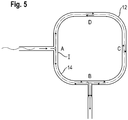
- FIG. 5 Another effect which aids in suppressing noise is shown in Figure 5 .
- the soundwave from the compressor enters into the first and second passages 12, 14 at point A.
- the wave is divided into two parts travelling upwards and downwards in the drawing.
- One soundwave moves clockwise in the drawing of Figure 5
- the respective other soundwave moves counterclockwise.
- the overall behaviour will depend on the sum of the lengths of the first and second passages and also on the wavelength. In particular, if the sum of the lengths of the first and second passages 12, 14 and the wavelength are the same, a standing wave will occur inside the first and second pipes 12, 14.
- Figure 6 shows the soundwave amplitude going clockwise while Figure 6b ) shows the soundwave amplitude going counter clockwise.
- Figure 6c shows the superposed soundwave of Figures 6a) and 6b ).
- Figure 6d shows, again, the soundwave amplitude moving clockwise for a different sound wave profile whilst Figure 6e ) shows the soundwave amplitude moving counterclockwise.
- Figure 6f shows, again the soundwave amplitude of the superimposed wave. Again, a reduction of the intensity is shown at point B.
- the muffler of the first embodiment significantly reduces the soundwave intensity.
- Figures 7 and 8 show a heat pump arrangement 110 according to another embodiment of the invention.
- the first connection passage 120 is identical to the corresponding first connection passage 20 of the first embodiment in that it extends perpendicularly relative to the first and second passages 112, 114.
- the second connection passage 122 is provided so that it extends in line with the outlet of the second passage 114 whilst being orthogonal to the outlet of the first passage 112. Accordingly, at this outlet, the sound travelling to the first passage 112 will, before it leaves the muffler, impinge on the reflection area B whilst the sound in the second passage 114 will not impinge on that reflection area B. However, still, a somewhat reduced output volume is achieved.
- first and second passages 120, 122 can be swapped - i.e. one can also connect the compressor to second connection passage 122 whilst connecting the indoor unit to the first connection passage 120.
- Figure 9 shows a heat pump arrangement 210 according to a third embodiment of the present invention.
- a first connection passage 220 is provided at a 45° angle relative to the first joining passage 217, which is in turn connected to the first passage 212 and the second passage 214.
- another angle such as between 30° and 60°
- the second connection passage 222 extends perpendicularly relative to the second joining passage 219.
- Such a muffler can be installed more space efficiently, since one does not need to have a first connection passage which extends at a 90° angle relative to the first and second passages 212, 214. Still, the muffling performance is satisfactory.
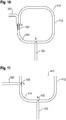
- Figure 10 shows a heat pump arrangement 310 according to a fourth embodiment of the present invention.
- the first connection passage 320 extends parallel to the first joining passage 317.
- the second connection passage 324 extends into the pipes forming the first passage 312 and the second passage 314.
- the latter feature leads to a reduction in the noise which is output, thanks to the obligatory change in direction.
- FIG 11 shows a fifth embodiment of a heat pump arrangement 410 of the present invention.
- both the first and the second connection passages 420, 422 extend perpendicularly relative to the first and second passages 412, 414.
- both the first and the second connection passages 420, 422 have a narrowed opening 430, 432 which extends into the pipes constituting the first and second passages 412, 414.
- Figure 12 shows a heat pump arrangement 510 according to a sixth embodiment of the present invention.
- both the first and the second connection passages 520, 522 extend parallel to the first and second joining passages 517, 519 connecting them to the first and second passages 512, 514.
- the direction changing effect of the soundwave is not as prominent, which reduces the sound volume, still, the previously mentioned interference effects occur and are beneficial in reducing the sound volume.
- FIG. 13 shows a heat pump arrangement 610 according to a seventh embodiment of the present invention.
- both the first and the second connection passages 620, 622 have narrowed openings 630, 632 which extend into the pipes forming the first and second passages 612, 614.
- the first passage comprises an M-shaped segment, with the bend 660 to create the M-shape being part of the first passage 612. This bend 6600 also reduces the sound volume.
- the seventh embodiment illustrates that between the points A and B, there can be pipes of whatever shape and whatever radius or connections.
- Figure 14 shows a heat pump arrangement 710 according to an eighth embodiment of the present invention.
- This embodiment is in some respects similar to the seventh embodiment in that the shape of the arrangement of first and second passages 712, 714 is quite similar.
- the first passage 712 comprises a bend 760 so that the first passage 712 is V-shaped.
- first and second connection passages 720, 722 extend into the pipe(s) forming the first and second passages 712, 714, where the first connection passage 720 serves as an inlet and the second connection passage 722 serves as an outlet.
- the first and second connection passages 720, 722 extend approximately parallel to one another.
- FIG 15 shows an air conditioning apparatus 1 which is a heat pump according to the invention.
- the air conditioning apparatus 1 includes a refrigerant circuit 7.
- the refrigerant circuit 7 is configured so that a compressor 2 for compressing a refrigerant, an indoor heat exchanger 3, an outdoor heat exchanger 4, and a four-way switch valve 5 are connected via a refrigerant piping 6 forming the refrigerant circuit 7.
- the four-way switch valve 5 switches the flow of refrigerant compressed by the compressor 2 to either the indoor heat exchanger (utilization side heat exchanger) 3 or the outdoor heat exchanger (heat source side heat exchanger) 4 .
- the air conditioning apparatus 1 further includes a pressure pulsation reducing component (muffler) 10, which is the muffler according to one of the preceding embodiments.
- the muffler 10 is provided between the four-way switch valve 5 and the indoor heat exchanger 3.
- the muffler 10 reduces pressure pulsations inside the refrigerant circuit 7 that are generated by the compressor 2. Further, the muffler 10 aims at reducing noise being produced by the compressor 2 from being propagated into the utilization side heat exchanger 3.
- an electromagnetic expansion valve 8 is connected to the refrigerant piping 6.
- the outdoor heat exchange 4, expansion valve 8, muffler 10, heat pump 2, four-way switch valve 5, and parts of the refrigerant piping 6 form an outdoor unit 9 of the air conditioning apparatus 1.
- the muffler 10 is provided as part of the outdoor unit 9 and is provided directly between the four-way switch valve 5 and the indoor unit 3, its position is not limited to this. As long as the muffler 10 is provided somewhere on the refrigerant piping 6, it will reduce pressure pulsation. In addition, the muffler 10 should be provided downstream of the compressor and upstream of the utilization side heat exchanger 3.
- first and second connection passages are connected to the first and second passages, one or more components selected from the group consisting of expansion mufflers, ⁇ -type filters, side branch mufflers, Helmholtz mufflers and interference mufflers.
Landscapes
- Engineering & Computer Science (AREA)
- Physics & Mathematics (AREA)
- Mechanical Engineering (AREA)
- Thermal Sciences (AREA)
- General Engineering & Computer Science (AREA)
- Compressor (AREA)
Abstract
Description
- The present invention relates to heat pumps and, in particular, to heat pumps comprising a muffler.
- Heat pumps, in particular heat pumps used with air-conditioners, produce noise when in operation due to the motor driving the compressor. It is clear that such a noise is to be reduced, in particular since air conditioners are often used in domestic and work environments where such noise would be seen as distracting.
- Accordingly, prior art documents such as
EP 2 058 609 A1 disclose the use of a pressure pulsation reducing component which is provided on the refrigerant piping of the heat pump of an air conditioner. The structure disclosed inEP 2 058 609 A1 is schematically shown inFig. 1 . As can be seen from that figure, refrigerant is introduced into a pipe 1 and has, as indicated by the sinusoidal wave, a pressure pulsation due to the compressor which introduces that refrigerant. This pipe 1 is then split up into two sub-pipes 2 and 3 at a point X, which are later joined together at a point Y so as to form outlet pipe 4 which leads to an indoor unit. Due to the different lengths of the travel of the soundwave through pipes 2 and 3, a phase shift occurs between them, which leads to a reduction in the volume of the noise which is transmitted to the indoor unit, thanks to interference between the soundwaves travelling through sub-pipes 2 and 3. - The present inventors have, however, realised that those solutions are inferior and, in particular, only lead to rather low level of sound reduction. Further, the noise is only reduced in a somewhat narrow frequency range, since one needs to have, as mentioned previously, an interference phenomenon. Such interference phenomena are frequency dependent, so that a significant reduction in the noise volume only occurs for a small range of frequencies.
- The present invention has been conceived in view of the problems noted previously and aims at providing a heat pump having a heat source heat exchanger and an utilisation side heat exchanger which are connected by refrigerant piping arranged so that the noise generated by the compressor is attenuated when it arrives at one of the heat exchangers. This reduction is to occur across a large range of a frequencies.
- The present invention is defined by claim 1. Preferred embodiments are defined in the dependent claims.
- According to claim 1, a heat pump comprises a heat source heat exchanger, a compressor, a utilisation side heat exchanger and an expansion valve connected by refrigerant piping. Such heat pumps are known from, for example, air conditioning units as are commonly available on the market. Such heat pumps are also often used in, for example, fridges or freezers but could also be used in domestic air conditioners or in air conditioners used in vehicles.
- The heat pump furthermore comprises a muffler, i.e. a device which reduces the noise produced by the compressor.
- The muffler comprises a first passage and a second passage. Those passages are pipes through which a refrigerant from the refrigerant piping can be led. Typically, the first passage and the second passage are connected to the refrigerant piping so that a refrigerant will flow from one part of the refrigerant piping into the first passage and the second passage and will then be led out of the first and the second passage to a different part of the refrigerant piping.
- Furthermore, there is provided a first junction which comprises a first connection passage connected to the refrigerant piping and a first joining passage connecting to and joining the first passage and the second passage. This the first junction is what connects the muffler via the first connection passage to the refrigerant piping. Put differently, the first connection passage is what connects the first junction to the refrigerant piping. The first joining passage connects the first connection passage to the first passage and the second passage. That is, refrigerant can flow from the first connection passage via the first joining passage to the first passage and the second passage. This first junction could be made of a pipe T-piece.
- The heat pump furthermore comprises a second junction. The second junction comprises a second connection passage connected to the refrigerant piping and a second joining passage connecting to and joining the first passage and the second passage. For the second junction, refrigerant which is flowing in the first and the second passages can enter into the second joining passage to then be led into the refrigerant piping via the second connection passage. Accordingly, the structures of the first and second junctions are essentially identical, with inverted functionalities. I.e., they can structurally be the same, but they differ in their functions: whilst the first junction is the junction where refrigerant enters into the muffler, the second junction is the junction where refrigerant leaves the muffler. Further, whilst the first junction has the purpose of reflecting as much noise as possible back into the compressor and to thus keep the noise outside of the muffler, the purpose of the second junction is to make sure that as little sound as possible leaves the muffler (since it could otherwise be transmitted to the utilization side heat exchanger it is connected to).
- Also the second junction could be made of a pipe T-piece.
- According to the invention, the first passage and the second passage are curved. That is, the first passage and the second passage both have a shape which has a bend and which thus cannot just be described as simply extending along a straight line.
- By the first passage and the second passage being curved, it is more likely that the soundwave of the noise will be travelling through the loop defined by those passages. Accordingly, there will be more interference between those waves, so that overall, the noise volume will be reduced. Compared with the prior art of, e.g.,
EP 2 058 609 A1 , where only one of the passages is curved, the sound intensity is reduced. - It is preferred that the first passage, the first joining passage, the second passage and the second joining passage form a loop. Through this formation of a loop, soundwaves existing within the first passage, the first joining passage, the second passage and the second joining passage can interfere with each other and thereby be reduced in their loudness. Accordingly, also a corresponding heat pump has a better muffling capability. By a loop, it is meant that those passages form an essentially closed circuit.
- It is preferred that the length of the first passage is substantially three times the length of the second passage. The lengths are measured between the respective junctions with the refrigerant piping. By "substantially", it is meant that the length of the first passage can only differ from three times the length of the second passage by ±15%. As will be explained in more detail below, such a design of the heat pump is particularly efficient when it comes to reducing noise, since the claimed relationship of the lengths is particularly advantageous when it comes to causing destructive interference at the second junction, so that the noise volume at that junction is reduced.
- It is preferred that the first connection passage is angled, at least in part, relative to the second connection passage. By having such an angle, the first connection passage is not parallel to the first joining passage, so that the noise entering via the first connection passage has a perpendicular component relative to the first joining passage. Since it will therefore impinge upon the material forming the first joining passage, rather than just flowing past it, there will be more noise reflections back into the compressor. Additionally, it will lose some of its energy at that point, which is beneficial for reducing the noise volume.
- In that context, it is particularly preferred if the first connection passage extends perpendicularly to the first joining passage. By having such a perpendicular arrangement of the first connection passage relative to the first joining passage, the effect of the impact of the noise and, hence, its reflection is particularly strong, thereby strongly reducing the sound volume.
- It is preferred that the first connection passage comprises a pipe having opposite first and second ends, wherein the first end is connected to the refrigerant piping and the second end is located within the first joining passage. Alternatively, or additionally, the second connection passage comprises a pipe having opposite first and second ends, wherein the first end is connected to the refrigerant piping and the second end is located within the second joining passage. By having the second ends of the respective first and/or second connection passages located within the respective first and second joining passage, refrigerant which enters into the first or second joining passage from the respective pipes of the first or second connection passages has to change its direction of flow somewhat, compared with a situation where the respective second end of the pipes of the first or second connection passages are linked to the pipes of the first and second joining passages but do not extend into those first and second joining passages. Since the ends are located within the respective joining passages, if noise propagates through them and enters into the first and second passages, it has to change direction. Likewise, if refrigerant is to flow out via one of those ends from the first and second passages, it also has to change direction. This forced change in direction is advantageous when it comes to reducing the noise volume, since it forces a loss in energy.
- It is furthermore preferred that an opening at the second end has a smaller cross-sectional area then an opening at the first end. Accordingly, the noise entering the muffler through the first connection passage hits the wall of the first joining passage in a narrow and more concentrated fashion, so that more noise is reflected and prevented from entering the muffler. On the other hand, less noise will leave the muffler through the second connection passage, because of the smaller cross-sectional area at the second end, i.e. the inlet into the second connection passage.
- In that context, it may for the same reason as above also be preferred if the second end is closed and at least one opening is provided in a shell of the pipe adjacent the second end. Thus, the noise volume is attenuated even more.
- It is furthermore preferred that a plurality of openings is provided in the shell of the pipe forming the refrigerant piping adjacent the second end. Again, this leads to a strong reduction in the sound volume, thanks to more significant changes of direction. Further, since the refrigerant has to go through those openings, a larger energy loss occurs, which, again, reduces the noise volume.
- It is preferred if the diameter of the first connection passage and/or of the second connection passage is smaller than the diameter of the first passage and/or the second passage. Again, in line with previous explanations as regards the narrowed opening, this leads to a more "concentrated" noise, which, in turn, reduces the noise volume entering the muffler. Further, thanks to the narrower cross-sectional area of the outlet, only a smaller fraction of the noise present in the muffler will actually leave the muffler.
- Additionally, it is preferred that the muffler is arranged on the refrigerant piping and is, in particular, positioned on that piping. This leads to a particularly quiet heat pump.
-
-
Figure 1 shows an arrangement according to the state of the art. -
Figure 2 shows schematically a heat pump arrangement according to a first embodiment. -
Figure 3 is a schematic drawing explaining the operation of the first embodiment. -
Figure 4 shows diagrams explaining the function of the first embodiment. -
Figure 5 is another explanatory diagram explaining the operation of the first embodiment. -
Figure 6 is a further explanatory diagram for the first embodiment. -
Figures 7 and8 show the operation of the second embodiment. -
Figure 9 shows the heat pump arrangement according to the third embodiment. -
Figure 10 shows the heat pump arrangement according to the fourth embodiment. -
Figure 11 shows the heat pump arrangement according to the fifth embodiment. -
Figure 12 shows the heat pump arrangement according to the sixth embodiment. -
Figure 13 shows the heat pump arrangement according to the seventh embodiment. -
Figure 14 shows the heat pump arrangement according to the eighth embodiment. -
Figure 15 shows a heat pump circuit to be used with the heat pump arrangement according to one of the preceding embodiments. -
Figure 2 shows the configuration of a heat pump arrangement according to a first embodiment of the invention. - A
first connection passage 20 is connected to the compressor 2 (seeFigure 15 ) of the heat pump 1 and leads into afirst passage 12 and asecond passage 14 arranged in a loop-like arrangement, i.e. an arrangement where noise (and refrigerant) can circulate in a single direction through the assembly made of thefirst passage 12 and thesecond passage 14. Thefirst connection passage 20 joins with thefirst passage 12 and thesecond passage 14 at a point A. At that point A, there is provided a first joiningpassage 17 which is linked to thefirst passage 12 and thesecond passage 14. - There is furthermore provided a second joining
passage 19 which is again connected to thefirst passage 12 and thesecond passage 14 and which is also connected to asecond connection passage 22. Thesecond connection passage 22 then leads to the indoor unit, particularly an utilization side heat exchanger. - Of note, the length of the
first passage 12 is three times the length of thesecond passage 14. In the present context, thefirst connection passage 20 and thesecond connection passage 22 could be formed of the same pipe which also forms thefirst passage 12 and thesecond passage 14. I.e., those components are not made of separate pipes that have been joined together but are made of a single pipe. - Sound which enters from the compressor via
first connection passage 20 will first impinge on the reflection area of the first joiningpassage 17 adjacent to the letter "A". Some of the sound will be reflected back to the compressor. Accordingly, the amplitude of the sound is already reduced by this reflection. - A second effect which leads to the reduction of noise is illustrated in
Figures 3 and 4 . - When a soundwave enters from the compressor, it will, at point A, be divided into two parts, which move clockwise and counter-clockwise in the first and
second passages second passages second passages first passage 12 and thesecond passage 14 at the point A. This tends to reduce the volume of the sound which then travels around the loop and which then leaves the muffler, thereby reducing noise volume. - This effect is also illustrated in
Figure 4 , whereFigure 4a ) show the input of the soundwave which comes from the compressor.Figure 4b ) shows the soundwave amplitude from the second round, andFigure 4c ) shows the superimposed soundwave fromFigures 4a) and 4b ). As can be seen, the amplitude of the soundwave is significantly reduced. - It has been found that the best length for this phenomenon is when the wavelength λ of the sound fulfils the relationship λ/2 = L1 + L3, where L1 is the length of the
second passage 14 and L2 is the length of thefirst passage 12. The attenuation effect is present for all wavelengths except λ = L1 + L2. It is, however, to be noted that in most cases, noise will comprise a wide range of frequencies, so that there will always be some frequencies which are reduced in their volume. Typically, the wavelength λ will be set by the frequency f of operation of the compressor and is related to the speed of sound v by v = λf. - Another effect which aids in suppressing noise is shown in
Figure 5 . The soundwave from the compressor enters into the first andsecond passages Figure 5 , and the respective other soundwave moves counterclockwise. At the different points within the pipe, there will be a superposition of those two counterpropagating waves. The overall behaviour will depend on the sum of the lengths of the first and second passages and also on the wavelength. In particular, if the sum of the lengths of the first andsecond passages second pipes - The nodes of the standing wave, which are the points of minimum intensity of the standing wave, will be at points B and D, and the antinodes, that is, the points of maximum intensity, will be at points A and C. If the second connection passage which leads to the indoor unit is connected to point B, as shown, the sound transfer to the indoor unit is very small, since it is connected to a node of the standing wave, again reducing the intensity of the sound volume. It has been found that the best length for this phenomenon is where λ = L1 + L2 and 3*L1=L2.
- This effect is also shown in
Figure 6 , whereFigure 6a ) shows the soundwave amplitude going clockwise whileFigure 6b ) shows the soundwave amplitude going counter clockwise. On the x-axis, the respective positions of the maxima/minima are denoted.Figure 6c ) shows the superposed soundwave ofFigures 6a) and 6b ). As can be seen, at position B, where the outlet is, the amplitude is very small.Figure 6d ) shows, again, the soundwave amplitude moving clockwise for a different sound wave profile whilstFigure 6e ) shows the soundwave amplitude moving counterclockwise.Figure 6f ) shows, again the soundwave amplitude of the superimposed wave. Again, a reduction of the intensity is shown at point B. - Accordingly, the muffler of the first embodiment significantly reduces the soundwave intensity.
-
Figures 7 and8 show aheat pump arrangement 110 according to another embodiment of the invention. Here, thefirst connection passage 120 is identical to the correspondingfirst connection passage 20 of the first embodiment in that it extends perpendicularly relative to the first andsecond passages second connection passage 122 is provided so that it extends in line with the outlet of thesecond passage 114 whilst being orthogonal to the outlet of thefirst passage 112. Accordingly, at this outlet, the sound travelling to thefirst passage 112 will, before it leaves the muffler, impinge on the reflection area B whilst the sound in thesecond passage 114 will not impinge on that reflection area B. However, still, a somewhat reduced output volume is achieved. This is also emphasised by what is shown inFigure 8 , where the respective flow directions of the soundwaves are indicated by arrows. It is to be noted that in the second embodiment, the respective first andsecond passages second connection passage 122 whilst connecting the indoor unit to thefirst connection passage 120. -
Figure 9 shows aheat pump arrangement 210 according to a third embodiment of the present invention. A first connection passage 220 is provided at a 45° angle relative to the first joiningpassage 217, which is in turn connected to thefirst passage 212 and thesecond passage 214. However, another angle (such as between 30° and 60°) would also be acceptable. The second connection passage 222 extends perpendicularly relative to the second joiningpassage 219. Such a muffler can be installed more space efficiently, since one does not need to have a first connection passage which extends at a 90° angle relative to the first andsecond passages -
Figure 10 shows aheat pump arrangement 310 according to a fourth embodiment of the present invention. Here, thefirst connection passage 320 extends parallel to the first joiningpassage 317. Furthermore, thesecond connection passage 324 extends into the pipes forming thefirst passage 312 and thesecond passage 314. In particular the latter feature leads to a reduction in the noise which is output, thanks to the obligatory change in direction. -
Figure 11 shows a fifth embodiment of a heat pump arrangement 410 of the present invention. Here, both the first and thesecond connection passages second passages second connection passages opening second passages second passages second passages second end 430 which is inserted into the pipes forming the first andsecond passages second end 432 at the outlet. -
Figure 12 shows aheat pump arrangement 510 according to a sixth embodiment of the present invention. Here, both the first and thesecond connection passages passages second passages -
Figure 13 shows aheat pump arrangement 610 according to a seventh embodiment of the present invention. In that embodiment, both the first and thesecond connection passages openings second passages - Furthermore, the first passage comprises an M-shaped segment, with the
bend 660 to create the M-shape being part of thefirst passage 612. This bend 6600 also reduces the sound volume. The seventh embodiment illustrates that between the points A and B, there can be pipes of whatever shape and whatever radius or connections. -
Figure 14 shows aheat pump arrangement 710 according to an eighth embodiment of the present invention. This embodiment is in some respects similar to the seventh embodiment in that the shape of the arrangement of first andsecond passages first passage 712 comprises abend 760 so that thefirst passage 712 is V-shaped. Again, first andsecond connection passages second passages first connection passage 720 serves as an inlet and thesecond connection passage 722 serves as an outlet. Compared with the seventh embodiment, where the first andsecond connection passages second connection passages -
Figure 15 shows an air conditioning apparatus 1 which is a heat pump according to the invention. The air conditioning apparatus 1 includes a refrigerant circuit 7. The refrigerant circuit 7 is configured so that a compressor 2 for compressing a refrigerant, an indoor heat exchanger 3, an outdoor heat exchanger 4, and a four-way switch valve 5 are connected via arefrigerant piping 6 forming the refrigerant circuit 7. The four-way switch valve 5 switches the flow of refrigerant compressed by the compressor 2 to either the indoor heat exchanger (utilization side heat exchanger) 3 or the outdoor heat exchanger (heat source side heat exchanger) 4 . - The air conditioning apparatus 1 further includes a pressure pulsation reducing component (muffler) 10, which is the muffler according to one of the preceding embodiments. The
muffler 10 is provided between the four-way switch valve 5 and the indoor heat exchanger 3. Themuffler 10 reduces pressure pulsations inside the refrigerant circuit 7 that are generated by the compressor 2. Further, themuffler 10 aims at reducing noise being produced by the compressor 2 from being propagated into the utilization side heat exchanger 3. Further, an electromagnetic expansion valve 8 is connected to therefrigerant piping 6. The outdoor heat exchange 4, expansion valve 8,muffler 10, heat pump 2, four-way switch valve 5, and parts of therefrigerant piping 6 form an outdoor unit 9 of the air conditioning apparatus 1. - Whilst it is the case that in the embodiment shown in
Figure 15 , themuffler 10 is provided as part of the outdoor unit 9 and is provided directly between the four-way switch valve 5 and the indoor unit 3, its position is not limited to this. As long as themuffler 10 is provided somewhere on therefrigerant piping 6, it will reduce pressure pulsation. In addition, themuffler 10 should be provided downstream of the compressor and upstream of the utilization side heat exchanger 3. - It is also possible to have before, after or between the points A and B where the first and second connection passages are connected to the first and second passages, one or more components selected from the group consisting of expansion mufflers, π-type filters, side branch mufflers, Helmholtz mufflers and interference mufflers.
- It is also possible to arrange several mufflers according to the present invention one after the other. This increases the sound attenuation.
Claims (13)
- Heat pump comprising
a heat source heat exchanger, a compressor, an utilization side heat exchanger and an expansion valve connected by refrigerant piping; and
a muffler (10) havinga first passage (12);a second passage (14);a first junction (16) comprising a first connection passage (20) connected to the refrigerant piping and a first joining passage (17) connecting to and joining the first passage and the second passage; anda second junction (18) comprising a second connection passage (22) connected to the refrigerant piping and a second joining passage (19) connecting to and joining the first passage and the second passage,wherein the first passage and the second passage are curved. - Heat pump according to claim 1, wherein the first passage (12), the first joining passage (17), the second passage (14) and the second joining passage (19) form a loop.
- Heat pump according to claim 1 or 2, wherein the length of the first passage (12) is substantially three times the length of the second passage (14).
- Heat pump according to any one of the preceding claims, wherein the first connection passage (220) is angled relative to the first joining passage (217).
- Heat pump according to claim 4, wherein the first connection passage (16) extends perpendicularly to the first joining passage (17).
- Heat pump according to any one of the preceding claims, wherein the second connection passage (22) is angled relative to the second joining passage (19).
- Heat pump according to claim 6, wherein the second connection passage (22) extends perpendicularly to the second joining passage (19).
- Heat pump according to any one of the preceding claims, wherein the first connection passage comprises a pipe having opposite first and second ends, wherein the first end is connected to the refrigerant piping and the second end is located within the first joining passage and/or the second connection passage comprises a pipe having opposite first and second ends, wherein the first end is connected to the refrigerant piping and the second end is located within the second joining passage.
- Heat pump according to claim 8, wherein an opening (430) at the second end has a smaller cross-sectional area than an opening at the first end.
- Heat pump according to claim 8, wherein the second end is closed and at least one opening is provided in a shell of the pipe adjacent the second end.
- Heat pump according to claim 8, 9 or 10, wherein a plurality of openings is provided in the shell of the pipe adjacent the second end.
- Heat pump according to any one of the preceding claims, wherein the diameter of the first connection passage and/or of the second connection passage is smaller than the diameter of the first passage and/or the second passage.
- Heat pump according to any one of the preceding claims, wherein the muffler is arranged on the refrigerant piping.
Priority Applications (1)
| Application Number | Priority Date | Filing Date | Title |
|---|---|---|---|
| EP19212127.5A EP3828482A1 (en) | 2019-11-28 | 2019-11-28 | Heat pump with a muffler |
Applications Claiming Priority (1)
| Application Number | Priority Date | Filing Date | Title |
|---|---|---|---|
| EP19212127.5A EP3828482A1 (en) | 2019-11-28 | 2019-11-28 | Heat pump with a muffler |
Publications (1)
| Publication Number | Publication Date |
|---|---|
| EP3828482A1 true EP3828482A1 (en) | 2021-06-02 |
Family
ID=68731838
Family Applications (1)
| Application Number | Title | Priority Date | Filing Date |
|---|---|---|---|
| EP19212127.5A Withdrawn EP3828482A1 (en) | 2019-11-28 | 2019-11-28 | Heat pump with a muffler |
Country Status (1)
| Country | Link |
|---|---|
| EP (1) | EP3828482A1 (en) |
Citations (4)
| Publication number | Priority date | Publication date | Assignee | Title |
|---|---|---|---|---|
| JPS58152516U (en) * | 1982-04-08 | 1983-10-12 | カルソニックカンセイ株式会社 | Silencer |
| JP2002061508A (en) * | 2000-08-23 | 2002-02-28 | Daikin Ind Ltd | Silencer |
| EP2048457A1 (en) * | 2006-08-01 | 2009-04-15 | Daikin Industries, Ltd. | Refrigeration device |
| EP2058609A1 (en) | 2006-08-11 | 2009-05-13 | Daikin Industries, Ltd. | Air conditioner |
-
2019
- 2019-11-28 EP EP19212127.5A patent/EP3828482A1/en not_active Withdrawn
Patent Citations (4)
| Publication number | Priority date | Publication date | Assignee | Title |
|---|---|---|---|---|
| JPS58152516U (en) * | 1982-04-08 | 1983-10-12 | カルソニックカンセイ株式会社 | Silencer |
| JP2002061508A (en) * | 2000-08-23 | 2002-02-28 | Daikin Ind Ltd | Silencer |
| EP2048457A1 (en) * | 2006-08-01 | 2009-04-15 | Daikin Industries, Ltd. | Refrigeration device |
| EP2058609A1 (en) | 2006-08-11 | 2009-05-13 | Daikin Industries, Ltd. | Air conditioner |
Similar Documents
| Publication | Publication Date | Title |
|---|---|---|
| CN101501420B (en) | Air conditioner | |
| JPH11325655A (en) | Silencers and air conditioners | |
| JP2014115653A (en) | General-purpose damping arrangement for air conditioning circuit | |
| EP3850281B1 (en) | Oil separator with integrated muffler | |
| US7578659B2 (en) | Compressor discharge muffler | |
| JP2005083732A (en) | Piping device for air conditioner | |
| CN115419600A (en) | Silencer and refrigerating system with same | |
| CN110749130A (en) | Piping assembly and refrigerating system | |
| EP3828413B1 (en) | Heat pump comprising a muffler | |
| CN102829581B (en) | For the gas distribution/junction station of the band noise elimination function of compressor bank refrigeration system | |
| JP2002061508A (en) | Silencer | |
| CN209944714U (en) | Muffler and Air Conditioner | |
| JPH09250844A (en) | Refrigeration cycle | |
| CN214500335U (en) | Pipes with sound-absorbing structure | |
| JPH05322379A (en) | Air conditioner refrigerant distributor | |
| CN104005960A (en) | Silencer and air conditioner with silencer | |
| CN207702765U (en) | A kind of refrigeration that can reduce noise or heat pump unit gas exhaust piping | |
| JPS5919780Y2 (en) | pressure pulsation dampener | |
| CN112097455B (en) | Pipeline silencer and refrigerator comprising same | |
| CN118776103A (en) | Muffler and air conditioning system having the same | |
| JP7765808B2 (en) | Silencer | |
| KR102840958B1 (en) | The noise suppresser | |
| EP4279784A1 (en) | Pipeline provided with silencing structure | |
| CN112785994B (en) | Muffler device and air conditioner | |
| CN118669620A (en) | Refrigerant pipe and refrigeration equipment |
Legal Events
| Date | Code | Title | Description |
|---|---|---|---|
| PUAI | Public reference made under article 153(3) epc to a published international application that has entered the european phase |
Free format text: ORIGINAL CODE: 0009012 |
|
| STAA | Information on the status of an ep patent application or granted ep patent |
Free format text: STATUS: THE APPLICATION HAS BEEN PUBLISHED |
|
| AK | Designated contracting states |
Kind code of ref document: A1 Designated state(s): AL AT BE BG CH CY CZ DE DK EE ES FI FR GB GR HR HU IE IS IT LI LT LU LV MC MK MT NL NO PL PT RO RS SE SI SK SM TR |
|
| STAA | Information on the status of an ep patent application or granted ep patent |
Free format text: STATUS: REQUEST FOR EXAMINATION WAS MADE |
|
| 17P | Request for examination filed |
Effective date: 20210623 |
|
| RBV | Designated contracting states (corrected) |
Designated state(s): AL AT BE BG CH CY CZ DE DK EE ES FI FR GB GR HR HU IE IS IT LI LT LU LV MC MK MT NL NO PL PT RO RS SE SI SK SM TR |
|
| GRAP | Despatch of communication of intention to grant a patent |
Free format text: ORIGINAL CODE: EPIDOSNIGR1 |
|
| STAA | Information on the status of an ep patent application or granted ep patent |
Free format text: STATUS: GRANT OF PATENT IS INTENDED |
|
| INTG | Intention to grant announced |
Effective date: 20220404 |
|
| STAA | Information on the status of an ep patent application or granted ep patent |
Free format text: STATUS: THE APPLICATION IS DEEMED TO BE WITHDRAWN |
|
| 18D | Application deemed to be withdrawn |
Effective date: 20220817 |