EP3828461A1 - Lamp and corresponding method - Google Patents
Lamp and corresponding method Download PDFInfo
- Publication number
- EP3828461A1 EP3828461A1 EP20206881.3A EP20206881A EP3828461A1 EP 3828461 A1 EP3828461 A1 EP 3828461A1 EP 20206881 A EP20206881 A EP 20206881A EP 3828461 A1 EP3828461 A1 EP 3828461A1
- Authority
- EP
- European Patent Office
- Prior art keywords
- light source
- lamp
- spring
- end caps
- support formations
- Prior art date
- Legal status (The legal status is an assumption and is not a legal conclusion. Google has not performed a legal analysis and makes no representation as to the accuracy of the status listed.)
- Granted
Links
Images


Classifications
-
- F—MECHANICAL ENGINEERING; LIGHTING; HEATING; WEAPONS; BLASTING
- F21—LIGHTING
- F21K—NON-ELECTRIC LIGHT SOURCES USING LUMINESCENCE; LIGHT SOURCES USING ELECTROCHEMILUMINESCENCE; LIGHT SOURCES USING CHARGES OF COMBUSTIBLE MATERIAL; LIGHT SOURCES USING SEMICONDUCTOR DEVICES AS LIGHT-GENERATING ELEMENTS; LIGHT SOURCES NOT OTHERWISE PROVIDED FOR
- F21K9/00—Light sources using semiconductor devices as light-generating elements, e.g. using light-emitting diodes [LED] or lasers
- F21K9/20—Light sources comprising attachment means
- F21K9/27—Retrofit light sources for lighting devices with two fittings for each light source, e.g. for substitution of fluorescent tubes
- F21K9/278—Arrangement or mounting of circuit elements integrated in the light source
-
- F—MECHANICAL ENGINEERING; LIGHTING; HEATING; WEAPONS; BLASTING
- F21—LIGHTING
- F21S—NON-PORTABLE LIGHTING DEVICES; SYSTEMS THEREOF; VEHICLE LIGHTING DEVICES SPECIALLY ADAPTED FOR VEHICLE EXTERIORS
- F21S43/00—Signalling devices specially adapted for vehicle exteriors, e.g. brake lamps, direction indicator lights or reversing lights
- F21S43/10—Signalling devices specially adapted for vehicle exteriors, e.g. brake lamps, direction indicator lights or reversing lights characterised by the light source
- F21S43/13—Signalling devices specially adapted for vehicle exteriors, e.g. brake lamps, direction indicator lights or reversing lights characterised by the light source characterised by the type of light source
- F21S43/14—Light emitting diodes [LED]
-
- F—MECHANICAL ENGINEERING; LIGHTING; HEATING; WEAPONS; BLASTING
- F21—LIGHTING
- F21S—NON-PORTABLE LIGHTING DEVICES; SYSTEMS THEREOF; VEHICLE LIGHTING DEVICES SPECIALLY ADAPTED FOR VEHICLE EXTERIORS
- F21S43/00—Signalling devices specially adapted for vehicle exteriors, e.g. brake lamps, direction indicator lights or reversing lights
- F21S43/10—Signalling devices specially adapted for vehicle exteriors, e.g. brake lamps, direction indicator lights or reversing lights characterised by the light source
- F21S43/13—Signalling devices specially adapted for vehicle exteriors, e.g. brake lamps, direction indicator lights or reversing lights characterised by the light source characterised by the type of light source
- F21S43/15—Strips of light sources
-
- F—MECHANICAL ENGINEERING; LIGHTING; HEATING; WEAPONS; BLASTING
- F21—LIGHTING
- F21S—NON-PORTABLE LIGHTING DEVICES; SYSTEMS THEREOF; VEHICLE LIGHTING DEVICES SPECIALLY ADAPTED FOR VEHICLE EXTERIORS
- F21S43/00—Signalling devices specially adapted for vehicle exteriors, e.g. brake lamps, direction indicator lights or reversing lights
- F21S43/10—Signalling devices specially adapted for vehicle exteriors, e.g. brake lamps, direction indicator lights or reversing lights characterised by the light source
- F21S43/19—Attachment of light sources or lamp holders
- F21S43/195—Details of lamp holders, terminals or connectors
-
- F—MECHANICAL ENGINEERING; LIGHTING; HEATING; WEAPONS; BLASTING
- F21—LIGHTING
- F21Y—INDEXING SCHEME ASSOCIATED WITH SUBCLASSES F21K, F21L, F21S and F21V, RELATING TO THE FORM OR THE KIND OF THE LIGHT SOURCES OR OF THE COLOUR OF THE LIGHT EMITTED
- F21Y2103/00—Elongate light sources, e.g. fluorescent tubes
- F21Y2103/10—Elongate light sources, e.g. fluorescent tubes comprising a linear array of point-like light-generating elements
-
- F—MECHANICAL ENGINEERING; LIGHTING; HEATING; WEAPONS; BLASTING
- F21—LIGHTING
- F21Y—INDEXING SCHEME ASSOCIATED WITH SUBCLASSES F21K, F21L, F21S and F21V, RELATING TO THE FORM OR THE KIND OF THE LIGHT SOURCES OR OF THE COLOUR OF THE LIGHT EMITTED
- F21Y2115/00—Light-generating elements of semiconductor light sources
- F21Y2115/10—Light-emitting diodes [LED]
Definitions
- One or more embodiments may be applied to lamps employing solid-state light generators, e.g. LED light generators.
- One or more embodiments may advantageously be employed in the automotive sector, e.g. as automotive retrofit lamps.
- Lamps (or bulbs) for the automotive sector are increasingly making use of solid-state light sources, e.g. LED sources.
- solid-state light sources e.g. LED sources.
- Such a lamp is described, e.g., in US 2018/0266636 A1 .
- a lamp which is adapted to be employed in the automotive sector such as e.g. a C5W bulb which may be used as a retrofit bulb
- a reliable operation over a rather wide temperature range e.g. -40°C to +65°C, such performance being verifiable through power thermal cycle (PCT) tests.
- PCT power thermal cycle
- Such lamps may include different materials (metal, plastics, carbon or ceramic materials, etc.) which may have rather different coefficients of thermal expansion. The risk therefore exists that such materials may undergo different elongations as a function of temperature, with a consequent potential damage to the lamp itself, e.g. to the light source.
- sources comprising a LED "filament” including light-generating chips mounted on a so-called leadframe with wire bonding connections
- the thermal stresses and the consequent elongations of the materials may lead to wire bonding being damaged, and therefore to jeopardizing lamp operation. This may take place even if the lamp is structured in such a way as to allow a certain movement of the source within the lamp housing.
- One or more embodiments aim at contributing to overcoming the drawbacks outlined in the foregoing.
- One or more embodiments may refer to a corresponding method.
- One or more embodiments facilitate designing lamps adapted to meet usage requirements in fields such as the automotive sector, with the capability of passing PCT tests over a temperature range of -40°C to +65°C without being damaged, and therefore improving the reliability and the lifetime of the lamp.
- reference 10 denotes an automotive lamp, e.g. a lamp known as C5W, adapted to be used for retrofitting or optionally for the first equipment of lights (high beam headlamps, low beam headlamps, fog lights, rear lights etc.) of a (motor) vehicle.
- an automotive lamp e.g. a lamp known as C5W, adapted to be used for retrofitting or optionally for the first equipment of lights (high beam headlamps, low beam headlamps, fog lights, rear lights etc.) of a (motor) vehicle.
- lamp 10 may have a shape substantially similar to a fuse, comprising a housing 12 extending in a longitudinal direction (axis X12 in the figures) between a pair of end caps 14 which are at least partly electrically conductive, between which there is arranged a light-permeable intermediate portion 16 (e.g. of a transparent or cut-out material).
- a light-permeable intermediate portion 16 e.g. of a transparent or cut-out material
- the end caps 14 may have a cup shape (e.g. a dome shape) and they may be applied and mounted, e.g. via end collars 140, onto the ends of the housing portion 16, which may have a tubular, e.g. cylindrical, shape.
- the end caps 14 may comprise electrically conductive material such as e.g. a metal material, with the light-permeable portion 16 which may comprise transparent plastic or glass material.
- a solid-state light source 18 e.g. a LED source, which may extend e.g. in the longitudinal direction of housing 12 (i.e. in the direction of axis X12, in the example shown in the figures).
- the source 18 may have an elongate shape, being supported within the cavity 20 of housing 12 by support formations 22 extending between the end caps 14 and the opposed ends of light source 18, which is arranged at the light-permeable portion 16.
- the support formations 22 are electrically conductive, therefore providing a power supply path extending between the end caps 14 through the light source 18.
- One or both support formations 22 may comprise resistors 220 provided with respective electrodes (rheophores) 222.
- the light source 18 may comprise a substrate 180 such as e.g. a so-called leadframe (or lead frame) of metal material, having mounted (fixed) thereon one or more solid-state light generators (e.g. LED chips) 182.
- a substrate 180 such as e.g. a so-called leadframe (or lead frame) of metal material, having mounted (fixed) thereon one or more solid-state light generators (e.g. LED chips) 182.
- the electrical connection of generators 182 may be provided by electrically conductive formations such as e.g. a so-called wire bonding structure (not visible in the figures because of the scale).
- the leadframe 180 and the generators 182 (as well as the wire bonding) may be embedded into a mass 184 of light-permeable material (such as a transparent resin) adapted to form a sort of protective sheath of light source 18.
- a lamp 10 as described so far in its general features with reference to Figures 1 and 2 is to be considered substantially known in the art, which makes it unnecessary to provide a more detailed description herein.
- the source 18 in such a lamp 10 may be considered as extending in a plane P18 which may substantially coincide, for example, with the extension or lying plane of substrate 180. Such plane is not visible in Figure 2 , where the light source 18 is viewed substantially in plan view.
- Figure 2 shows that the support formations 22 may be considered as extending in a plane P22 which may substantially coincide, for example, with a plane wherein electrodes 222 extend: in an example as shown in Figure 2 such a plane may be e.g. any transversal or diametral plane of the lamp.
- planes such as planes P18 and P22 as considered herein must not necessarily pass through axis X12; as can be seen in some of the figures they may be offset from said axis.
- the various elements of a lamp 10 as considered herein may include elements of different materials (e.g. end caps 14 of a metal material, intermediate portion 16 of a plastic material or glass, resistors 220 of carbon or ceramic material, etc.) having coefficients of thermal expansion (CTEs) which are correspondingly different.
- Such elements may therefore experience different elongations as a function of temperature: such a phenomenon may pose a risk of damaging the lamp, e.g. at the wire bonding of source 18.
- the possible drawbacks described in the foregoing may be countered by providing at least one element (or optionally more elements) of the light source 18 and/or the support formations 22 with at least one spring-like element 100.
- Such an element is adapted to originate a portion with enhanced deformability in the longitudinal direction of the body of lamp 10 (e.g. in the direction of axis X12 exemplified in the figures).
- the spring-like element 100 may comprise a curvilinear (i.e. non-straight), e.g. meandering, portion.
- the latter may be e.g. a portion of the light source 18 (e.g. of substrate 180) and/or of at least one of the support formations 22, which extends out of the plane of the light source 18 and/or out of the plane of at least one of the support formations 22.
- the spring-like element 100 may comprise a soft and compliant, e.g. electrically conductive, material.
- the spring-like element 100 may have a width L (as measured in the longitudinal direction of lamp 10, i.e. in the direction of axis X12, in the presently exemplified embodiments) which may vary, and therefore absorb the strains (stresses) which may be input into the structure of lamp 10, deriving from different length variations which the components of lamp 10 may experience due to their different coefficients of thermal expansion, as a consequence of the exposure to a thermal cycle.
- such a spring-like element 100 (which may exhibit enhanced deformability, or a deformability which is concentrated with respect to the adjoining portions) may be arranged at the light source 18, at least at one of the support formations 22 (optionally comprising resistor 220) or else at all said possible positions (light source 18 and one or both support formations 22).
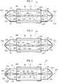
- Figure 3 refers to an element 100 provided in the leadframe 180 of light source 18 and having e.g. an omega shape.
- Figures 4 and 5 exemplify embodiments comprising one (or more, in the case of Figure 5 ) elements 100, having a similar arrangement, and having:
- Figures such as Figures 6 to 10 exemplify the possibility of providing elements 100 at the support formations 22.
- one of the electrodes (rheophores) 222 of resistor 220 - e.g. the leftmost electrode in Figure 6 - may have a coiled shape having an axial length L1, such a length being adapted to vary because such shape causes the element to behave substantially as a helical spring, which is again adapted to absorb strains or stresses which may derive from a thermal cycle, according to what has been stated in the foregoing.
- Figure 5 shows a first example of the possible simultaneous presence of a plurality of spring-like elements 100, which in this case are provided at the light source 18, e.g. on opposed sides of leadframe 180, the lengths whereof (which are respectively denoted as L1 and L2) are both adapted to vary, so as to originate a cooperative action for absorbing the thermal deformation stresses.
- Figure 6 shows a second example of the possible simultaneous presence of a plurality of spring-like elements 100, one provided by the coiled shape of one of the electrodes 222 of the leftmost resistor 220 in Figure 6 , and the other provided at the light source 18, the respective lengths L1 and L2 whereof, once again, are both adapted to vary, so as to originate a cooperative action for absorbing the thermal deformation stresses.
- Spring-like elements 100 as shown in the presently annexed Figures may therefore be implemented as a single element 100, which may be arranged:
- Figure 7 exemplifies (on the left side of the Figure) the possibility of providing a spring-like element 100 at one (or optionally both) support formations 22, by imparting to the electrodes (rheophores) 222 a curvilinear shape (e.g. a U shape), so as to originate a curvilinear or meandering portion having the general shape of an S or a serpentine, the resistor 220 being arranged in a central position.
- a curvilinear shape e.g. a U shape
- the spring-like element 100 having such a shape may have again a variable length L1, so as to perform (optionally together with a further element 100 arranged at light source 18 and having a length L2) an action of absorbing the thermal deformation stresses.
- Figure 8 exemplifies embodiments provided with an element 100 having a length L1, including a wire-like member having a coiled shape similar to the element 100 visible in the left part of Figure 6 .
- One or more embodiments as exemplified in Figure 8 may be considered as virtually corresponding to the option (which may be applied also in embodiments as exemplified in the other figures) of omitting one or both resistors 220 (the presence whereof is not strictly mandatory in itself) by imparting to one or more electrodes 222 a curvilinear or meandering shape, such as the coiled shape which is visible on the left part of Figure 8 .
- the "omission" of one of resistors 220 may be compensated for by the provision, on the opposed side (on the right side, in the presently exemplified embodiment) of an enhanced resistor 220, which is adapted to improve the dissipation, by a single resistor, of the power which originally was supposed to be dissipated by two resistors.
- One or more embodiments may envisage the presence of one or more spring-like elements 100 which extend, at least partially, out of a plane of at least one of the light source 18 and the support formations 22.
- a plane P18 of the source 18 may substantially coincide, e.g., with the extension or lying plane of substrate 180, while a plane P22 of the support formations 22 may substantially coincide, for example, with a plane wherein the electrodes 222 extend (at least at their rear ends).
- the planes P18 and P22 must not necessarily pass through axis X12, as they may be offset from said axis, as may be seen in some of the Figures.
- Figure 3 shows a situation wherein an element 100 extends nearly completely out of the plane P18 of source 18, the same considerations applying, for example, to similar spring-like elements 100 which are visible e.g. in Figure 4 or (with length L2) in Figures 9 and 10 .
- one or more spring-like elements 100 as explained herein may be considered as extending both out of plane P18 of light source 18 and out of one or more planes P22 (e.g. parallel to plane P18 of source 18) of the support formations 22, such planes being identifiable according to the criteria discussed in the foregoing, i.e. as the planes wherein the electrodes 222 (at least at the outer ends thereof) lie.
- such mechanism of exiting a plane may be considered as originating a spring-like behaviour thanks to a beam buckling phenomenon.
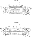
- Figures 9 and 10 exemplify the possibility of providing, in one of the support formations 22 (on the right side of the example shown in the figures), a spring-like element 100 comprising a deformable, e.g. elastically deformable, electrically conductive element 222', i.e. a soft conductive element.
- a spring-like element 100 comprising a deformable, e.g. elastically deformable, electrically conductive element 222', i.e. a soft conductive element.
- element 222' may be the only spring-like element present in lamp 10.
- element 222' may be present together with other spring-like elements 100, which may be similar to it or different from the former.
- element 222' may represent a sort of interface portion of electrode 222 facing the corresponding end cap (the end cap 14 towards which electrode 222 extends), said interface portion being adapted to vary its length L1 while performing the function of absorbing stresses, already repeatedly explained in the foregoing.
- said electrode is adapted to adopt, thanks to the presence of said (widened) interface end portion, a general T shape or mushroom shape.
- element 222' may comprise an electrically conductive adhesive, e.g. a silicone or epoxy adhesive.
- an electrically conductive adhesive e.g. a silicone or epoxy adhesive.
- the adhesives available under the trademarks Henkel ICP 4000 or QMI 516 IE, or other electrically conductive silicone adhesives which are used e.g. for shielding gaskets against electromagnetic interference (EMI shielding gaskets) exemplify materials which may be used in one or more embodiments.
- element 222' may comprise a spongy electrically conductive material, e.g. of the kind used as a sponge and/or shielding against electromagnetic interference (EMI conductive sponge and/or EMI shielding).
- EMI conductive sponge and/or EMI shielding electromagnetic interference
- the material 222' may be inserted without appreciably altering the value of electrical resistance which may be detected across the end caps 14.
- element 222' is adapted to perform the function of absorbing the stresses by cooperating with another element 100 of length L2, which is provided e.g. at the leadframe 180, e.g. of the kind exemplified in any of the Figures 3 to 7 .
- Such an element 222' (or a similar element) may also be used alone, or in order to implement a portion 100 at any other of the positions exemplified herein.
- An automotive solid-state lamp (e.g. 10) for a vehicle may comprise:
- the strains (stresses) which may be induced into the lamp structure due to the different length variations that the various components may undergo because of their different coefficients of thermal expansion (for example after the exposure to a thermal cycle) may be concentrated in an enhanced or concentrated deformation region, which is provided in at least one of the light source and the support formations. It is thus possible to originate a variation of lengths L, L1 or L2, i.e. a deformation which takes place locally, (only) at the spring-like element, while avoiding deformation effects which may involve the light source and/or the support formations on the whole, with the negative consequences which may arise therefrom (referring to an example already mentioned in the foregoing, damage to the wire bonding of the light source).
- the light source may comprise a support member (e.g. a laminar support member such as 180) having at least one light generator (e.g. 182) thereon, with said at least one spring-like element provided at said support member of the light source.
- a support member e.g. a laminar support member such as 180
- at least one light generator e.g. 182
- the support member may comprise a leadframe of the light source, which carries at least one light-generating chip thereon.
- At least one of the support formations may comprise a wire-like member (e.g. an electrode or rheophore 222), with said at least one spring-like element provided at said wire-like member.
- a wire-like member e.g. an electrode or rheophore 222
- said at least one of the support formations may comprise a resistor (e.g. 220) having wire-like electrodes (e.g. 222), with at least one of said wire-like electrodes (222) comprising said at least one spring-like element.
- a resistor e.g. 220
- wire-like electrodes e.g. 222
- said at least one of the support formations may comprise a resistor having a pair of opposed wire-like electrodes, wherein said wire-like electrodes in the pair provide said at least one spring-like element (see for example Figure 7 ) .
- said at least one spring-like element may comprise a curvilinear or meandering element. This may consist for example of a portion of light source 18 (e.g. of substrate 180) and/or at least one of the support formations 22, which extends out of the plane of light source 18 (e.g. substrate 180) and/or out of the plane of at least one of the support formations 22 (e.g. passing through the outer ends of electrodes 222).
- said at least one spring-like element may have a shape selected out of an omega shape, a V shape, a U shape, a Z shape, an S shape (see e.g. Figures 3 to 5 and also Figures 6 and 7 as well as 9 and 10) and a coiled shape (see e.g. Figures 6 and 8 , on the left side).
- said at least one spring-like element may extend out of a plane (e.g. P18, P22) of at least one of the light source and the support formations.
- said at least one spring-like element may comprise soft electrically conductive material (see for example reference 222' in Figures 9 and 10 ).
- At least one of said support formations may comprise said soft electrically conductive material (e.g. 222') at an interface position with a respective end cap of the housing.
- the solid-state light source may comprise at least one LED light generator (e.g. 182).
- a method of providing a lamp as exemplified herein may comprise:
- Lamp 10 Housing 12 End cap 14 End cap collar 140 Light-permeable portion 16 (LED) light source 18 Substrate (leadframe) 180 Light-emitting chip 182 Protective resin 184 Housing cavity 20 Support formation 22 Resistor 220 Resistor electrode (rheophore) 222 Longitudinal axis of housing X12 Supply voltage V Spring-like element 100 Variable length of spring-like portion L, L1, L2 Soft conductive element 222' Plane of the source P18 Plane of the support formation P22
Landscapes
- Engineering & Computer Science (AREA)
- General Engineering & Computer Science (AREA)
- Physics & Mathematics (AREA)
- Microelectronics & Electronic Packaging (AREA)
- Optics & Photonics (AREA)
- Fastening Of Light Sources Or Lamp Holders (AREA)
Abstract
Description
- The description refers to lamps.
- One or more embodiments may be applied to lamps employing solid-state light generators, e.g. LED light generators.
- One or more embodiments may advantageously be employed in the automotive sector, e.g. as automotive retrofit lamps.
- Lamps (or bulbs) for the automotive sector are increasingly making use of solid-state light sources, e.g. LED sources. Such a lamp is described, e.g., in
US 2018/0266636 A1 . - In such an environment, thermal stresses play a significant role.
- For a lamp which is adapted to be employed in the automotive sector, such as e.g. a C5W bulb which may be used as a retrofit bulb, it is desirable to have a reliable operation over a rather wide temperature range, e.g. -40°C to +65°C, such performance being verifiable through power thermal cycle (PCT) tests.
- Such lamps may include different materials (metal, plastics, carbon or ceramic materials, etc.) which may have rather different coefficients of thermal expansion. The risk therefore exists that such materials may undergo different elongations as a function of temperature, with a consequent potential damage to the lamp itself, e.g. to the light source.
- For example, in sources comprising a LED "filament" including light-generating chips mounted on a so-called leadframe with wire bonding connections, the thermal stresses and the consequent elongations of the materials may lead to wire bonding being damaged, and therefore to jeopardizing lamp operation. This may take place even if the lamp is structured in such a way as to allow a certain movement of the source within the lamp housing.
- One or more embodiments aim at contributing to overcoming the drawbacks outlined in the foregoing.
- According to one or more embodiments, such an object can be achieved thanks to a lamp having the features set forth in the claims that follow.
- One or more embodiments may refer to a corresponding method.
- The claims are an integral part of the technical teaching provided herein with reference to embodiments.
- One or more embodiments facilitate designing lamps adapted to meet usage requirements in fields such as the automotive sector, with the capability of passing PCT tests over a temperature range of -40°C to +65°C without being damaged, and therefore improving the reliability and the lifetime of the lamp.
- One or more embodiments will now be described, by way of non-limiting example only, with reference to the annexed figures, wherein:
-
Figures 1 and 2 are a side view and a partially cut-away view of a conventional automotive lamp, respectively, and -
Figures 3 to 10 exemplify embodiments according to the present description, in a view substantially corresponding to the view ofFigure 2 . - In the following description, various specific details are given to provide a thorough understanding of various exemplary embodiments according to the specification. The embodiments may be implemented without one or several specific details, or with other methods, components, materials, etc. In other instances, well-known structures, materials or operations are not shown or described in detail in order to avoid obscuring the various aspects of the embodiments.
- Reference throughout this specification to "an embodiment" or "one embodiment" means that a particular feature, structure or characteristic described in connection with the embodiment is included in at least one embodiment. Thus, the possible appearances of the phrases "in an embodiment" or "in one embodiment" in various places throughout the present specification are not necessarily all referring to one and the same embodiment. Furthermore, particular features, structures, or characteristics may be combined in any suitable manner in one or more embodiments.
- The references/headings provided herein are given for convenience only, and therefore do not interpret the extent of protection or scope of the embodiments.
- As a general introduction, it is to be noted that features and characteristics which are exemplified - either individually or in mutual combination - with reference to any of the annexed figures are adapted to be applied - either individually or in combination - to embodiments according to any other annexed Figure.
- Therefore, the description of a given feature or characteristic with reference to a specific figure shall not be construed, not even indirectly, as implying that such feature or characteristic is uniquely adapted to be used (only) in embodiments exemplified in the corresponding figure. In other words, the features and characteristics illustrated herein with reference to the annexed figures are adapted to be freely transferred from one embodiment to another of the embodiments as exemplified herein.
- In the figures,
reference 10 denotes an automotive lamp, e.g. a lamp known as C5W, adapted to be used for retrofitting or optionally for the first equipment of lights (high beam headlamps, low beam headlamps, fog lights, rear lights etc.) of a (motor) vehicle. - According to a solution which may be considered as conventional per se (see
Figures 1 and 2 ),lamp 10 may have a shape substantially similar to a fuse, comprising ahousing 12 extending in a longitudinal direction (axis X12 in the figures) between a pair ofend caps 14 which are at least partly electrically conductive, between which there is arranged a light-permeable intermediate portion 16 (e.g. of a transparent or cut-out material). - In one or more embodiments, the
end caps 14 may have a cup shape (e.g. a dome shape) and they may be applied and mounted, e.g. viaend collars 140, onto the ends of thehousing portion 16, which may have a tubular, e.g. cylindrical, shape. - In one or more embodiments, the
end caps 14 may comprise electrically conductive material such as e.g. a metal material, with the light-permeable portion 16 which may comprise transparent plastic or glass material. - Within the
housing 12 there is arranged a solid-state light source 18, e.g. a LED source, which may extend e.g. in the longitudinal direction of housing 12 (i.e. in the direction of axis X12, in the example shown in the figures). - As exemplified herein, the
source 18 may have an elongate shape, being supported within thecavity 20 ofhousing 12 bysupport formations 22 extending between theend caps 14 and the opposed ends oflight source 18, which is arranged at the light-permeable portion 16. - As exemplified herein, the
support formations 22 are electrically conductive, therefore providing a power supply path extending between theend caps 14 through thelight source 18. - In that way, a supply voltage V applied across the
end caps 14 is transferred tosource 18, which is therefore activated, with a consequent light emission through theportion 16 which is permeable to the light of thelamp 10. - One or both
support formations 22 may compriseresistors 220 provided with respective electrodes (rheophores) 222. - The
light source 18 may comprise asubstrate 180 such as e.g. a so-called leadframe (or lead frame) of metal material, having mounted (fixed) thereon one or more solid-state light generators (e.g. LED chips) 182. - The electrical connection of
generators 182 may be provided by electrically conductive formations such as e.g. a so-called wire bonding structure (not visible in the figures because of the scale). Theleadframe 180 and the generators 182 (as well as the wire bonding) may be embedded into amass 184 of light-permeable material (such as a transparent resin) adapted to form a sort of protective sheath oflight source 18. - A
lamp 10 as described so far in its general features with reference toFigures 1 and 2 is to be considered substantially known in the art, which makes it unnecessary to provide a more detailed description herein. - For the purposes herein, it will be noted that the
source 18 in such a lamp 10 (see for instanceFigure 1 ) may be considered as extending in a plane P18 which may substantially coincide, for example, with the extension or lying plane ofsubstrate 180. Such plane is not visible inFigure 2 , where thelight source 18 is viewed substantially in plan view. - On the other hand,
Figure 2 shows that thesupport formations 22 may be considered as extending in a plane P22 which may substantially coincide, for example, with a plane whereinelectrodes 222 extend: in an example as shown inFigure 2 such a plane may be e.g. any transversal or diametral plane of the lamp. - On the other hand, it will be observed that planes such as planes P18 and P22 as considered herein must not necessarily pass through axis X12; as can be seen in some of the figures they may be offset from said axis.
- As discussed in the introduction to the present specification, the various elements of a
lamp 10 as considered herein may include elements of different materials (e.g. end caps 14 of a metal material,intermediate portion 16 of a plastic material or glass,resistors 220 of carbon or ceramic material, etc.) having coefficients of thermal expansion (CTEs) which are correspondingly different. Such elements may therefore experience different elongations as a function of temperature: such a phenomenon may pose a risk of damaging the lamp, e.g. at the wire bonding ofsource 18. - In one or more embodiments, the possible drawbacks described in the foregoing may be countered by providing at least one element (or optionally more elements) of the
light source 18 and/or thesupport formations 22 with at least one spring-like element 100. - Such an element is adapted to originate a portion with enhanced deformability in the longitudinal direction of the body of lamp 10 (e.g. in the direction of axis X12 exemplified in the figures).
- In one or more embodiments, the spring-
like element 100 may comprise a curvilinear (i.e. non-straight), e.g. meandering, portion. - The latter may be e.g. a portion of the light source 18 (e.g. of substrate 180) and/or of at least one of the
support formations 22, which extends out of the plane of thelight source 18 and/or out of the plane of at least one of thesupport formations 22. - In one or more embodiments, the spring-
like element 100 may comprise a soft and compliant, e.g. electrically conductive, material. - Whatever the chosen implementation may be, the spring-
like element 100 may have a width L (as measured in the longitudinal direction oflamp 10, i.e. in the direction of axis X12, in the presently exemplified embodiments) which may vary, and therefore absorb the strains (stresses) which may be input into the structure oflamp 10, deriving from different length variations which the components oflamp 10 may experience due to their different coefficients of thermal expansion, as a consequence of the exposure to a thermal cycle. - In one or more embodiments, such a spring-like element 100 (which may exhibit enhanced deformability, or a deformability which is concentrated with respect to the adjoining portions) may be arranged at the
light source 18, at least at one of the support formations 22 (optionally comprising resistor 220) or else at all said possible positions (light source 18 and one or both support formations 22). - For example,
Figure 3 refers to anelement 100 provided in theleadframe 180 oflight source 18 and having e.g. an omega shape. -
Figures 4 and 5 exemplify embodiments comprising one (or more, in the case ofFigure 5 )elements 100, having a similar arrangement, and having: - a V shape (or in other words a U shape), see
Figure 4 , - a Z shape (or in other words an S shape), see
Figure 5 . - Figures such as
Figures 6 to 10 exemplify the possibility of providingelements 100 at thesupport formations 22. - For example, one of the electrodes (rheophores) 222 of resistor 220 - e.g. the leftmost electrode in
Figure 6 - may have a coiled shape having an axial length L1, such a length being adapted to vary because such shape causes the element to behave substantially as a helical spring, which is again adapted to absorb strains or stresses which may derive from a thermal cycle, according to what has been stated in the foregoing. -
Figure 5 shows a first example of the possible simultaneous presence of a plurality of spring-like elements 100, which in this case are provided at thelight source 18, e.g. on opposed sides ofleadframe 180, the lengths whereof (which are respectively denoted as L1 and L2) are both adapted to vary, so as to originate a cooperative action for absorbing the thermal deformation stresses. -
Figure 6 shows a second example of the possible simultaneous presence of a plurality of spring-like elements 100, one provided by the coiled shape of one of theelectrodes 222 of theleftmost resistor 220 inFigure 6 , and the other provided at thelight source 18, the respective lengths L1 and L2 whereof, once again, are both adapted to vary, so as to originate a cooperative action for absorbing the thermal deformation stresses. - Spring-
like elements 100 as shown in the presently annexed Figures may therefore be implemented as asingle element 100, which may be arranged: - either at
light source 18, as exemplified inFigures 3 to 4 , or - at either
support formation 22, as exemplified inFigure 8 which will be further explained in the following. - As stated in the foregoing, it is also possible to envisage the simultaneous presence of two (or more) spring-
like elements 100 which are arranged, for example: - both at light source 18 (see e.g.
Figure 5 ), - one at
light source 18 and the other at one of the support formations 22 (see for exampleFigure 6 orFigures 7 ,9 and 10 , which will be further explained in the following); - at both support formations 22:
atlight source 18 and at bothsupport formations 22. - The last two possibilities are not explicitly exemplified in the figures; however, as discussed in the introduction to the present specification, it must be borne in mind that elements and characteristics shown - individually or in mutual combination - with reference to any of the annexed figures are adapted to be applied - individually or in mutual combination - to embodiments according to any other of the annexed figures.
-
Figure 7 exemplifies (on the left side of the Figure) the possibility of providing a spring-like element 100 at one (or optionally both)support formations 22, by imparting to the electrodes (rheophores) 222 a curvilinear shape (e.g. a U shape), so as to originate a curvilinear or meandering portion having the general shape of an S or a serpentine, theresistor 220 being arranged in a central position. - The spring-
like element 100 having such a shape may have again a variable length L1, so as to perform (optionally together with afurther element 100 arranged atlight source 18 and having a length L2) an action of absorbing the thermal deformation stresses. -
Figure 8 exemplifies embodiments provided with anelement 100 having a length L1, including a wire-like member having a coiled shape similar to theelement 100 visible in the left part ofFigure 6 . - One or more embodiments as exemplified in
Figure 8 may be considered as virtually corresponding to the option (which may be applied also in embodiments as exemplified in the other figures) of omitting one or both resistors 220 (the presence whereof is not strictly mandatory in itself) by imparting to one or more electrodes 222 a curvilinear or meandering shape, such as the coiled shape which is visible on the left part ofFigure 8 . - In one or more embodiments as exemplified in
Figure 8 , the "omission" of one of resistors 220 (e.g. the resistor on the left side of the Figure, in the presently exemplified embodiment) may be compensated for by the provision, on the opposed side (on the right side, in the presently exemplified embodiment) of anenhanced resistor 220, which is adapted to improve the dissipation, by a single resistor, of the power which originally was supposed to be dissipated by two resistors. - One or more embodiments may envisage the presence of one or more spring-
like elements 100 which extend, at least partially, out of a plane of at least one of thelight source 18 and thesupport formations 22. - As already discussed with reference to
Figures 1 and 2 , a plane P18 of thesource 18 may substantially coincide, e.g., with the extension or lying plane ofsubstrate 180, while a plane P22 of thesupport formations 22 may substantially coincide, for example, with a plane wherein theelectrodes 222 extend (at least at their rear ends). As already stated in the foregoing, the planes P18 and P22 must not necessarily pass through axis X12, as they may be offset from said axis, as may be seen in some of the Figures. -
Figure 3 shows a situation wherein anelement 100 extends nearly completely out of the plane P18 ofsource 18, the same considerations applying, for example, to similar spring-like elements 100 which are visible e.g. inFigure 4 or (with length L2) inFigures 9 and 10 . - Moreover, as will be appreciated especially in the case of either spring-
like element 100 of the example ofFigure 5 , one or more spring-like elements 100 as explained herein may be considered as extending both out of plane P18 oflight source 18 and out of one or more planes P22 (e.g. parallel to plane P18 of source 18) of thesupport formations 22, such planes being identifiable according to the criteria discussed in the foregoing, i.e. as the planes wherein the electrodes 222 (at least at the outer ends thereof) lie. - It will be noted that such considerations also apply to the spring-
like elements 100 having length L2, which are visible, for example, inFigure 6 or inFigure 7 . - In the case of
Figure 7 , whereinsource 18 is seen in plan view, so that plane P18 is not visible, it is possible to identify also a plane P22 of thesupport formations 22 which is at least approximately transversal to plane P18, with the portions ofelectrodes 222, which comprise theresistor 220 between them (and which may define a spring-like element 100), extending out of said plane P22. - In the case of
Figures 6 and8 , which show wire-shaped members which are wound in a helix or a coil and which are adapted to define a spring-like element 100, the helical or coiled shape is such that the corresponding spring-like element extends, at least partially, out of any plane P22 which may be defined by referring at least to the outer ends of electrodes 222 (and optionally out of plane P18 of source 18). - Without wishing to be bound by any specific theory, in one or more embodiments such mechanism of exiting a plane (P18 and/or P22, for example) may be considered as originating a spring-like behaviour thanks to a beam buckling phenomenon.
- Once again, one has to bear in mind that the presence and the description of a given feature or characteristic with reference to a given Figure must not be construed, not even indirectly, as implying that such a feature or characteristic is uniquely adapted to be used (only) in embodiments exemplified in the corresponding figure.
- In other words, the features and characteristics illustrated herein with reference to the annexed Figures are adapted to be freely transferred from one to another of the presently exemplified embodiments.
-
Figures 9 and 10 exemplify the possibility of providing, in one of the support formations 22 (on the right side of the example shown in the figures), a spring-like element 100 comprising a deformable, e.g. elastically deformable, electrically conductive element 222', i.e. a soft conductive element. - In one or more embodiments, element 222' may be the only spring-like element present in
lamp 10. - In one or more embodiments, on the other hand, element 222' may be present together with other spring-
like elements 100, which may be similar to it or different from the former. - In one or more embodiments as exemplified in
Figures 9 and 10 , element 222' may represent a sort of interface portion ofelectrode 222 facing the corresponding end cap (theend cap 14 towards which electrode 222 extends), said interface portion being adapted to vary its length L1 while performing the function of absorbing stresses, already repeatedly explained in the foregoing. - Moreover, said electrode is adapted to adopt, thanks to the presence of said (widened) interface end portion, a general T shape or mushroom shape.
- In one or more embodiments, as exemplified in
Figure 9 , element 222' may comprise an electrically conductive adhesive, e.g. a silicone or epoxy adhesive. The adhesives available under the trademarks Henkel ICP 4000 or QMI 516 IE, or other electrically conductive silicone adhesives which are used e.g. for shielding gaskets against electromagnetic interference (EMI shielding gaskets) exemplify materials which may be used in one or more embodiments. - In one or more embodiments as exemplified in
Figure 10 , which is globally similar toFigure 9 , element 222' may comprise a spongy electrically conductive material, e.g. of the kind used as a sponge and/or shielding against electromagnetic interference (EMI conductive sponge and/or EMI shielding). - It will be appreciated that, although it may be considered an additional element, which may lead to shortening the body of the corresponding electrode, the material 222' may be inserted without appreciably altering the value of electrical resistance which may be detected across the end caps 14.
- In one or more embodiments as exemplified in
Figures 9 and 10 , element 222' is adapted to perform the function of absorbing the stresses by cooperating with anotherelement 100 of length L2, which is provided e.g. at theleadframe 180, e.g. of the kind exemplified in any of theFigures 3 to 7 . - Such an element 222' (or a similar element) may also be used alone, or in order to implement a
portion 100 at any other of the positions exemplified herein. - Once again, if a certain feature or characteristic is explained herein with reference to a certain figure, this does not imply, not even indirectly, that such a feature or characteristic is uniquely adapted to be used (only) in the embodiments exemplified in the corresponding figure. In other words, the features and characteristics illustrated herein with reference to the annexed figures may be freely transferred from one embodiment to any other embodiment exemplified herein.
- An automotive solid-state lamp (e.g. 10) for a vehicle, as exemplified herein, may comprise:
- a housing (e.g. 12) extending in a longitudinal direction (e.g. X12) between opposed electrically conductive end caps (e.g. 14) with a light-permeable portion (e.g. 16) between the end caps,
- a solid-state light source (e.g. 18) arranged at the light-permeable portion of the housing,
- electrically-conductive support formations (e.g. 22) between the end caps and the light source, the support formations being configured to support the light source and to provide a power supply path between the end caps through the light source,
- wherein the lamp comprises at least one spring-like element (e.g. 100) in at least one of the light source and the support formations, the at least one spring-like element having a length (e.g. L; L1; L2) in said longitudinal direction and being deformable to vary said length in said longitudinal direction.
- In this way, the strains (stresses) which may be induced into the lamp structure due to the different length variations that the various components may undergo because of their different coefficients of thermal expansion (for example after the exposure to a thermal cycle) may be concentrated in an enhanced or concentrated deformation region, which is provided in at least one of the light source and the support formations. It is thus possible to originate a variation of lengths L, L1 or L2, i.e. a deformation which takes place locally, (only) at the spring-like element, while avoiding deformation effects which may involve the light source and/or the support formations on the whole, with the negative consequences which may arise therefrom (referring to an example already mentioned in the foregoing, damage to the wire bonding of the light source).
- In a lamp as exemplified herein, the light source may comprise a support member (e.g. a laminar support member such as 180) having at least one light generator (e.g. 182) thereon, with said at least one spring-like element provided at said support member of the light source.
- In a lamp as exemplified herein, the support member may comprise a leadframe of the light source, which carries at least one light-generating chip thereon.
- In a lamp as exemplified herein, at least one of the support formations may comprise a wire-like member (e.g. an electrode or rheophore 222), with said at least one spring-like element provided at said wire-like member.
- In a lamp as exemplified herein, said at least one of the support formations may comprise a resistor (e.g. 220) having wire-like electrodes (e.g. 222), with at least one of said wire-like electrodes (222) comprising said at least one spring-like element.
- In a lamp as exemplified herein, said at least one of the support formations may comprise a resistor having a pair of opposed wire-like electrodes, wherein said wire-like electrodes in the pair provide said at least one spring-like element (see for example
Figure 7 ) . - In a lamp as exemplified herein, said at least one spring-like element may comprise a curvilinear or meandering element. This may consist for example of a portion of light source 18 (e.g. of substrate 180) and/or at least one of the
support formations 22, which extends out of the plane of light source 18 (e.g. substrate 180) and/or out of the plane of at least one of the support formations 22 (e.g. passing through the outer ends of electrodes 222). - In a lamp as exemplified herein, said at least one spring-like element may have a shape selected out of an omega shape, a V shape, a U shape, a Z shape, an S shape (see e.g.
Figures 3 to 5 and alsoFigures 6 and7 as well as 9 and 10) and a coiled shape (see e.g.Figures 6 and8 , on the left side). - In a lamp as exemplified herein, said at least one spring-like element may extend out of a plane (e.g. P18, P22) of at least one of the light source and the support formations.
- In a lamp as exemplified herein, said at least one spring-like element may comprise soft electrically conductive material (see for example reference 222' in
Figures 9 and 10 ). - In a lamp as exemplified herein, at least one of said support formations (see for
example formation 22 on the right side inFigures 9 and 10 ) may comprise said soft electrically conductive material (e.g. 222') at an interface position with a respective end cap of the housing. - In a lamp as exemplified herein:
- the end caps and the light-permeable portion of the housing,
- the light source, and
- the support formations
- may comprise materials having different coefficients of thermal expansion.
- In a lamp as exemplified herein, the solid-state light source may comprise at least one LED light generator (e.g. 182).
- A method of providing a lamp as exemplified herein may comprise:
- arranging a solid-state light source in a housing extending in a longitudinal direction between electrically conductive opposed end caps, with a light-permeable portion of the housing between the end caps,
- supporting the solid-state light source arranged at the light-permeable portion of the housing via electrically conductive support formations between the end caps and the light source, the support formations being configured to provide a power supply path between the end caps through the light source,
- providing at least one spring-like element (100) in at least one of the light source and the support formations, the at least one spring-like element having a length in said longitudinal direction and being deformable in order to vary said length in said longitudinal direction.
- Without prejudice to the basic principles, the implementation details and the embodiments may vary, even appreciably, without departing from the extent of protection.
- Said extent of protection is defined by the annexed claims.
-
Lamp 10 Housing 12 End cap 14 End cap collar 140 Light-permeable portion 16 (LED) light source 18 Substrate (leadframe) 180 Light-emitting chip 182 Protective resin 184 Housing cavity 20 Support formation 22 Resistor 220 Resistor electrode (rheophore) 222 Longitudinal axis of housing X12 Supply voltage V Spring- like element 100 Variable length of spring-like portion L, L1, L2 Soft conductive element 222' Plane of the source P18 Plane of the support formation P22
Claims (14)
- An automotive solid-state lamp (10) for a vehicle, comprising:a housing (12) extending in a longitudinal direction (X12) between opposed electrically-conductive end caps (14) with a light-permeable portion (16) of the housing between the end caps (14),a solid-state light source (18) arranged at the light-permeable portion (16) of the housing (12),electrically-conductive support formations (22) between the end caps (14) and the light source (18), the support formations (22) configured to support the light source (18) and to provide a power supply path between the end caps (14) through the light source (18),wherein the lamp (10) comprises at least one spring-like element (100) in at least one of the light source (18) and the support formations (22), the at least one spring-like element (100) having a length (L; L1, L2) in said longitudinal direction (X12) and being deformable to vary said length (L; L1, L2) in said longitudinal direction (X12).
- The lamp (10) of claim 1, wherein the solid-state light source (18) comprises a support member (180) having at least one light generator (182) thereon with said at least one spring-like element (100) provided at said support member (180) of the light source (18).
- The lamp (10) of claim 2, wherein the support member comprises a leadframe (180) of the light source (18), the leadframe (180) having at least one light-generating chip (182) thereon.
- The lamp (10) of any of the previous claims, wherein at least one of the support formations (22) comprises a wire-like member (222) with said at least one spring-like element (100) provided at said wire-like member (222).
- The lamp (10) of claim 4, wherein said at least one of the support formations (22) comprises a resistor (220) having wire-like electrodes (222) with at least one of said wire-like electrodes (222) comprising said at least one spring-like element (100).
- The lamp (10) of claim 5, wherein said at least one of the support formations (22) comprises a resistor (220) having a pair of opposed wire-like electrodes (222), wherein said wire-like electrodes (222) in the pair provide said at least one spring-like element (100) .
- The lamp (10) of any of the previous claims, wherein said at least one spring-like element (100) comprises a curvilinear element.
- The lamp (10) of any of the previous claims, wherein said at least one spring-like element (100) has a shape selected out of an omega shape, a V shape, a U shape, a Z shape, a S shape and a coiled shape.
- The lamp (10) of any of the previous claims, wherein said at least one spring-like element (100) extends out of a plane (P18, P22) of at least one of the light source (18) and the support formations (22).
- The lamp (10) of any of the previous claims, wherein said at least one spring-like element (100) comprises soft electrically-conductive material (222').
- The lamp (10) of claim 10, wherein at least one of said support formations (22) comprises said soft electrically-conductive material (222') at an interface position with a respective end cap (14) of the housing (12) .
- The lamp (10) of any of the previous claims, wherein the end caps (14) and the light-permeable portion (16) of the housing (12), the light source (18) and the support formations (22) comprise materials having different coefficients of thermal expansion.
- The lamp (10) of any of the previous claims, wherein the solid-state light source (18) comprises at least one LED light radiation generator (182).
- A method of providing a lighting lamp (10), the method comprising:arranging a solid-state light source (18) in a housing (12) extending in a longitudinal direction (X12) between electrically conductive opposed end caps (14) with a light-permeable portion (16) of the housing between the end caps (14),supporting the solid-state light source (18) arranged at the light-permeable portion (16) of the housing (12) via electrically-conductive support formations (22) between the end caps (14) and the light source (18), the support formations (22) configured to provide a power supply path between the end caps (14) through the light source (18),providing at least one spring-like element (100) in at least one of the light source (18) and the support formations (22), the at least one spring-like element (100) having a length (L; L1, L2) in said longitudinal direction (X12) and being deformable to vary said length (L; L1, L2) in said longitudinal direction (X12).
Applications Claiming Priority (1)
| Application Number | Priority Date | Filing Date | Title |
|---|---|---|---|
| IT102019000022149A IT201900022149A1 (en) | 2019-11-26 | 2019-11-26 | LAMP AND CORRESPONDING PROCEDURE |
Publications (2)
| Publication Number | Publication Date |
|---|---|
| EP3828461A1 true EP3828461A1 (en) | 2021-06-02 |
| EP3828461B1 EP3828461B1 (en) | 2023-12-27 |
Family
ID=70009097
Family Applications (1)
| Application Number | Title | Priority Date | Filing Date |
|---|---|---|---|
| EP20206881.3A Active EP3828461B1 (en) | 2019-11-26 | 2020-11-11 | Lamp and corresponding method |
Country Status (2)
| Country | Link |
|---|---|
| EP (1) | EP3828461B1 (en) |
| IT (1) | IT201900022149A1 (en) |
Citations (3)
| Publication number | Priority date | Publication date | Assignee | Title |
|---|---|---|---|---|
| JP2004241191A (en) * | 2003-02-04 | 2004-08-26 | Koito Mfg Co Ltd | Light bulb with base |
| KR20090008551U (en) * | 2008-02-21 | 2009-08-26 | 최성 | LED lamp for vehicle interior |
| US20180266636A1 (en) | 2017-03-16 | 2018-09-20 | Osram Gmbh | Lighting device and corresponding method |
Family Cites Families (1)
| Publication number | Priority date | Publication date | Assignee | Title |
|---|---|---|---|---|
| TW201617548A (en) * | 2014-11-06 | 2016-05-16 | 艾笛森光電股份有限公司 | LED lamp core structure |
-
2019
- 2019-11-26 IT IT102019000022149A patent/IT201900022149A1/en unknown
-
2020
- 2020-11-11 EP EP20206881.3A patent/EP3828461B1/en active Active
Patent Citations (3)
| Publication number | Priority date | Publication date | Assignee | Title |
|---|---|---|---|---|
| JP2004241191A (en) * | 2003-02-04 | 2004-08-26 | Koito Mfg Co Ltd | Light bulb with base |
| KR20090008551U (en) * | 2008-02-21 | 2009-08-26 | 최성 | LED lamp for vehicle interior |
| US20180266636A1 (en) | 2017-03-16 | 2018-09-20 | Osram Gmbh | Lighting device and corresponding method |
Also Published As
| Publication number | Publication date |
|---|---|
| IT201900022149A1 (en) | 2021-05-26 |
| EP3828461B1 (en) | 2023-12-27 |
Similar Documents
| Publication | Publication Date | Title |
|---|---|---|
| RU2591041C2 (en) | Diode illumination device | |
| JP7116076B2 (en) | LED lamp | |
| US20130230995A1 (en) | Electrical connector header for an led-based light | |
| DE102014213561A1 (en) | Band-shaped illuminating device, lamp and method for producing the band-shaped luminous means device | |
| JP4866975B2 (en) | LED lamp and lighting fixture | |
| CN109973837B (en) | LED module with stable lead frame | |
| JP6748333B1 (en) | Flexible light emitting diode lighting strip with interposer | |
| CN102563481A (en) | Light source unit of semiconductor-type light source of vehicle lighting device and vehicle lighting device | |
| CA3010745C (en) | Led light emitting strip and arrangement of led light emitting strips | |
| CN102330934A (en) | Light source unit of semiconductor-type light source of vehicle lighting device and vehicle lighting device | |
| US8436538B2 (en) | Compact fluorescent lamp with mechanical support means and starting aid | |
| WO2015012084A1 (en) | Light source device and vehicle lamp | |
| JPS62131459A (en) | Discharge lamp with cap for head light | |
| KR101130022B1 (en) | Led lighting lamp | |
| EP3828461B1 (en) | Lamp and corresponding method | |
| EP2272078A1 (en) | Lamp and method of manufacturing a lamp | |
| CN111664372A (en) | Strip-shaped lighting device, lamp and method for manufacturing strip-shaped lighting device | |
| US20100181910A1 (en) | High-pressure discharge lamp comprising a starter antenna | |
| EP3376831B1 (en) | A lighting device and corresponding method | |
| EP3290773B1 (en) | Led light bulb and fabrication method thereof | |
| JP2014086224A (en) | Led bulb | |
| CN112204702A (en) | Flash discharge tube and flash device using the same | |
| KR20070095403A (en) | 램프 lamp assembly comprising an enhancer and reflector plate for lamp assembly | |
| EP3091275B1 (en) | A method of assembling lighting devices and corresponding device | |
| CN110676362B (en) | Omnidirectional luminous LED light source applied to automobile illumination |
Legal Events
| Date | Code | Title | Description |
|---|---|---|---|
| PUAI | Public reference made under article 153(3) epc to a published international application that has entered the european phase |
Free format text: ORIGINAL CODE: 0009012 |
|
| STAA | Information on the status of an ep patent application or granted ep patent |
Free format text: STATUS: THE APPLICATION HAS BEEN PUBLISHED |
|
| AK | Designated contracting states |
Kind code of ref document: A1 Designated state(s): AL AT BE BG CH CY CZ DE DK EE ES FI FR GB GR HR HU IE IS IT LI LT LU LV MC MK MT NL NO PL PT RO RS SE SI SK SM TR |
|
| STAA | Information on the status of an ep patent application or granted ep patent |
Free format text: STATUS: REQUEST FOR EXAMINATION WAS MADE |
|
| 17P | Request for examination filed |
Effective date: 20210910 |
|
| RBV | Designated contracting states (corrected) |
Designated state(s): AL AT BE BG CH CY CZ DE DK EE ES FI FR GB GR HR HU IE IS IT LI LT LU LV MC MK MT NL NO PL PT RO RS SE SI SK SM TR |
|
| STAA | Information on the status of an ep patent application or granted ep patent |
Free format text: STATUS: EXAMINATION IS IN PROGRESS |
|
| 17Q | First examination report despatched |
Effective date: 20221215 |
|
| GRAP | Despatch of communication of intention to grant a patent |
Free format text: ORIGINAL CODE: EPIDOSNIGR1 |
|
| STAA | Information on the status of an ep patent application or granted ep patent |
Free format text: STATUS: GRANT OF PATENT IS INTENDED |
|
| RIC1 | Information provided on ipc code assigned before grant |
Ipc: F21Y 115/10 20160101ALN20230601BHEP Ipc: F21Y 103/10 20160101ALN20230601BHEP Ipc: F21S 43/19 20180101ALI20230601BHEP Ipc: F21S 43/15 20180101ALI20230601BHEP Ipc: F21S 43/14 20180101ALI20230601BHEP Ipc: F21K 9/278 20160101AFI20230601BHEP |
|
| RIC1 | Information provided on ipc code assigned before grant |
Ipc: F21Y 115/10 20160101ALN20230607BHEP Ipc: F21Y 103/10 20160101ALN20230607BHEP Ipc: F21S 43/19 20180101ALI20230607BHEP Ipc: F21S 43/15 20180101ALI20230607BHEP Ipc: F21S 43/14 20180101ALI20230607BHEP Ipc: F21K 9/278 20160101AFI20230607BHEP |
|
| INTG | Intention to grant announced |
Effective date: 20230626 |
|
| GRAS | Grant fee paid |
Free format text: ORIGINAL CODE: EPIDOSNIGR3 |
|
| GRAA | (expected) grant |
Free format text: ORIGINAL CODE: 0009210 |
|
| STAA | Information on the status of an ep patent application or granted ep patent |
Free format text: STATUS: THE PATENT HAS BEEN GRANTED |
|
| AK | Designated contracting states |
Kind code of ref document: B1 Designated state(s): AL AT BE BG CH CY CZ DE DK EE ES FI FR GB GR HR HU IE IS IT LI LT LU LV MC MK MT NL NO PL PT RO RS SE SI SK SM TR |
|
| P01 | Opt-out of the competence of the unified patent court (upc) registered |
Effective date: 20231120 |
|
| REG | Reference to a national code |
Ref country code: GB Ref legal event code: FG4D |
|
| REG | Reference to a national code |
Ref country code: CH Ref legal event code: EP |
|
| REG | Reference to a national code |
Ref country code: DE Ref legal event code: R096 Ref document number: 602020023318 Country of ref document: DE |
|
| REG | Reference to a national code |
Ref country code: IE Ref legal event code: FG4D |
|
| PG25 | Lapsed in a contracting state [announced via postgrant information from national office to epo] |
Ref country code: GR Free format text: LAPSE BECAUSE OF FAILURE TO SUBMIT A TRANSLATION OF THE DESCRIPTION OR TO PAY THE FEE WITHIN THE PRESCRIBED TIME-LIMIT Effective date: 20240328 |
|
| REG | Reference to a national code |
Ref country code: LT Ref legal event code: MG9D |
|
| PG25 | Lapsed in a contracting state [announced via postgrant information from national office to epo] |
Ref country code: LT Free format text: LAPSE BECAUSE OF FAILURE TO SUBMIT A TRANSLATION OF THE DESCRIPTION OR TO PAY THE FEE WITHIN THE PRESCRIBED TIME-LIMIT Effective date: 20231227 |
|
| PG25 | Lapsed in a contracting state [announced via postgrant information from national office to epo] |
Ref country code: ES Free format text: LAPSE BECAUSE OF FAILURE TO SUBMIT A TRANSLATION OF THE DESCRIPTION OR TO PAY THE FEE WITHIN THE PRESCRIBED TIME-LIMIT Effective date: 20231227 |
|
| PG25 | Lapsed in a contracting state [announced via postgrant information from national office to epo] |
Ref country code: LT Free format text: LAPSE BECAUSE OF FAILURE TO SUBMIT A TRANSLATION OF THE DESCRIPTION OR TO PAY THE FEE WITHIN THE PRESCRIBED TIME-LIMIT Effective date: 20231227 Ref country code: GR Free format text: LAPSE BECAUSE OF FAILURE TO SUBMIT A TRANSLATION OF THE DESCRIPTION OR TO PAY THE FEE WITHIN THE PRESCRIBED TIME-LIMIT Effective date: 20240328 Ref country code: FI Free format text: LAPSE BECAUSE OF FAILURE TO SUBMIT A TRANSLATION OF THE DESCRIPTION OR TO PAY THE FEE WITHIN THE PRESCRIBED TIME-LIMIT Effective date: 20231227 Ref country code: ES Free format text: LAPSE BECAUSE OF FAILURE TO SUBMIT A TRANSLATION OF THE DESCRIPTION OR TO PAY THE FEE WITHIN THE PRESCRIBED TIME-LIMIT Effective date: 20231227 Ref country code: BG Free format text: LAPSE BECAUSE OF FAILURE TO SUBMIT A TRANSLATION OF THE DESCRIPTION OR TO PAY THE FEE WITHIN THE PRESCRIBED TIME-LIMIT Effective date: 20240327 |
|
| REG | Reference to a national code |
Ref country code: NL Ref legal event code: MP Effective date: 20231227 |
|
| REG | Reference to a national code |
Ref country code: AT Ref legal event code: MK05 Ref document number: 1644825 Country of ref document: AT Kind code of ref document: T Effective date: 20231227 |
|
| PG25 | Lapsed in a contracting state [announced via postgrant information from national office to epo] |
Ref country code: NL Free format text: LAPSE BECAUSE OF FAILURE TO SUBMIT A TRANSLATION OF THE DESCRIPTION OR TO PAY THE FEE WITHIN THE PRESCRIBED TIME-LIMIT Effective date: 20231227 |
|
| PG25 | Lapsed in a contracting state [announced via postgrant information from national office to epo] |
Ref country code: SE Free format text: LAPSE BECAUSE OF FAILURE TO SUBMIT A TRANSLATION OF THE DESCRIPTION OR TO PAY THE FEE WITHIN THE PRESCRIBED TIME-LIMIT Effective date: 20231227 Ref country code: RS Free format text: LAPSE BECAUSE OF FAILURE TO SUBMIT A TRANSLATION OF THE DESCRIPTION OR TO PAY THE FEE WITHIN THE PRESCRIBED TIME-LIMIT Effective date: 20231227 Ref country code: NO Free format text: LAPSE BECAUSE OF FAILURE TO SUBMIT A TRANSLATION OF THE DESCRIPTION OR TO PAY THE FEE WITHIN THE PRESCRIBED TIME-LIMIT Effective date: 20240327 Ref country code: NL Free format text: LAPSE BECAUSE OF FAILURE TO SUBMIT A TRANSLATION OF THE DESCRIPTION OR TO PAY THE FEE WITHIN THE PRESCRIBED TIME-LIMIT Effective date: 20231227 Ref country code: LV Free format text: LAPSE BECAUSE OF FAILURE TO SUBMIT A TRANSLATION OF THE DESCRIPTION OR TO PAY THE FEE WITHIN THE PRESCRIBED TIME-LIMIT Effective date: 20231227 Ref country code: HR Free format text: LAPSE BECAUSE OF FAILURE TO SUBMIT A TRANSLATION OF THE DESCRIPTION OR TO PAY THE FEE WITHIN THE PRESCRIBED TIME-LIMIT Effective date: 20231227 |
|
| PG25 | Lapsed in a contracting state [announced via postgrant information from national office to epo] |
Ref country code: IS Free format text: LAPSE BECAUSE OF FAILURE TO SUBMIT A TRANSLATION OF THE DESCRIPTION OR TO PAY THE FEE WITHIN THE PRESCRIBED TIME-LIMIT Effective date: 20240427 |
|
| PG25 | Lapsed in a contracting state [announced via postgrant information from national office to epo] |
Ref country code: AT Free format text: LAPSE BECAUSE OF FAILURE TO SUBMIT A TRANSLATION OF THE DESCRIPTION OR TO PAY THE FEE WITHIN THE PRESCRIBED TIME-LIMIT Effective date: 20231227 Ref country code: CZ Free format text: LAPSE BECAUSE OF FAILURE TO SUBMIT A TRANSLATION OF THE DESCRIPTION OR TO PAY THE FEE WITHIN THE PRESCRIBED TIME-LIMIT Effective date: 20231227 |
|
| PG25 | Lapsed in a contracting state [announced via postgrant information from national office to epo] |
Ref country code: SK Free format text: LAPSE BECAUSE OF FAILURE TO SUBMIT A TRANSLATION OF THE DESCRIPTION OR TO PAY THE FEE WITHIN THE PRESCRIBED TIME-LIMIT Effective date: 20231227 |
|
| PG25 | Lapsed in a contracting state [announced via postgrant information from national office to epo] |
Ref country code: SM Free format text: LAPSE BECAUSE OF FAILURE TO SUBMIT A TRANSLATION OF THE DESCRIPTION OR TO PAY THE FEE WITHIN THE PRESCRIBED TIME-LIMIT Effective date: 20231227 Ref country code: SK Free format text: LAPSE BECAUSE OF FAILURE TO SUBMIT A TRANSLATION OF THE DESCRIPTION OR TO PAY THE FEE WITHIN THE PRESCRIBED TIME-LIMIT Effective date: 20231227 Ref country code: RO Free format text: LAPSE BECAUSE OF FAILURE TO SUBMIT A TRANSLATION OF THE DESCRIPTION OR TO PAY THE FEE WITHIN THE PRESCRIBED TIME-LIMIT Effective date: 20231227 Ref country code: IT Free format text: LAPSE BECAUSE OF FAILURE TO SUBMIT A TRANSLATION OF THE DESCRIPTION OR TO PAY THE FEE WITHIN THE PRESCRIBED TIME-LIMIT Effective date: 20231227 Ref country code: IS Free format text: LAPSE BECAUSE OF FAILURE TO SUBMIT A TRANSLATION OF THE DESCRIPTION OR TO PAY THE FEE WITHIN THE PRESCRIBED TIME-LIMIT Effective date: 20240427 Ref country code: EE Free format text: LAPSE BECAUSE OF FAILURE TO SUBMIT A TRANSLATION OF THE DESCRIPTION OR TO PAY THE FEE WITHIN THE PRESCRIBED TIME-LIMIT Effective date: 20231227 Ref country code: CZ Free format text: LAPSE BECAUSE OF FAILURE TO SUBMIT A TRANSLATION OF THE DESCRIPTION OR TO PAY THE FEE WITHIN THE PRESCRIBED TIME-LIMIT Effective date: 20231227 Ref country code: AT Free format text: LAPSE BECAUSE OF FAILURE TO SUBMIT A TRANSLATION OF THE DESCRIPTION OR TO PAY THE FEE WITHIN THE PRESCRIBED TIME-LIMIT Effective date: 20231227 |
|
| PG25 | Lapsed in a contracting state [announced via postgrant information from national office to epo] |
Ref country code: PL Free format text: LAPSE BECAUSE OF FAILURE TO SUBMIT A TRANSLATION OF THE DESCRIPTION OR TO PAY THE FEE WITHIN THE PRESCRIBED TIME-LIMIT Effective date: 20231227 Ref country code: PT Free format text: LAPSE BECAUSE OF FAILURE TO SUBMIT A TRANSLATION OF THE DESCRIPTION OR TO PAY THE FEE WITHIN THE PRESCRIBED TIME-LIMIT Effective date: 20240429 |
|
| PG25 | Lapsed in a contracting state [announced via postgrant information from national office to epo] |
Ref country code: PT Free format text: LAPSE BECAUSE OF FAILURE TO SUBMIT A TRANSLATION OF THE DESCRIPTION OR TO PAY THE FEE WITHIN THE PRESCRIBED TIME-LIMIT Effective date: 20240429 Ref country code: PL Free format text: LAPSE BECAUSE OF FAILURE TO SUBMIT A TRANSLATION OF THE DESCRIPTION OR TO PAY THE FEE WITHIN THE PRESCRIBED TIME-LIMIT Effective date: 20231227 |
|
| REG | Reference to a national code |
Ref country code: DE Ref legal event code: R097 Ref document number: 602020023318 Country of ref document: DE |
|
| PG25 | Lapsed in a contracting state [announced via postgrant information from national office to epo] |
Ref country code: DK Free format text: LAPSE BECAUSE OF FAILURE TO SUBMIT A TRANSLATION OF THE DESCRIPTION OR TO PAY THE FEE WITHIN THE PRESCRIBED TIME-LIMIT Effective date: 20231227 |
|
| PG25 | Lapsed in a contracting state [announced via postgrant information from national office to epo] |
Ref country code: DK Free format text: LAPSE BECAUSE OF FAILURE TO SUBMIT A TRANSLATION OF THE DESCRIPTION OR TO PAY THE FEE WITHIN THE PRESCRIBED TIME-LIMIT Effective date: 20231227 |
|
| PLBE | No opposition filed within time limit |
Free format text: ORIGINAL CODE: 0009261 |
|
| STAA | Information on the status of an ep patent application or granted ep patent |
Free format text: STATUS: NO OPPOSITION FILED WITHIN TIME LIMIT |
|
| 26N | No opposition filed |
Effective date: 20240930 |
|
| PG25 | Lapsed in a contracting state [announced via postgrant information from national office to epo] |
Ref country code: SI Free format text: LAPSE BECAUSE OF FAILURE TO SUBMIT A TRANSLATION OF THE DESCRIPTION OR TO PAY THE FEE WITHIN THE PRESCRIBED TIME-LIMIT Effective date: 20231227 |
|
| REG | Reference to a national code |
Ref country code: CH Ref legal event code: PL |
|
| PG25 | Lapsed in a contracting state [announced via postgrant information from national office to epo] |
Ref country code: MC Free format text: LAPSE BECAUSE OF FAILURE TO SUBMIT A TRANSLATION OF THE DESCRIPTION OR TO PAY THE FEE WITHIN THE PRESCRIBED TIME-LIMIT Effective date: 20231227 |
|
| PG25 | Lapsed in a contracting state [announced via postgrant information from national office to epo] |
Ref country code: LU Free format text: LAPSE BECAUSE OF NON-PAYMENT OF DUE FEES Effective date: 20241111 |
|
| REG | Reference to a national code |
Ref country code: CH Ref legal event code: PL |
|
| GBPC | Gb: european patent ceased through non-payment of renewal fee |
Effective date: 20241111 |
|
| PG25 | Lapsed in a contracting state [announced via postgrant information from national office to epo] |
Ref country code: CH Free format text: LAPSE BECAUSE OF NON-PAYMENT OF DUE FEES Effective date: 20241130 |
|
| REG | Reference to a national code |
Ref country code: BE Ref legal event code: MM Effective date: 20241130 |
|
| PG25 | Lapsed in a contracting state [announced via postgrant information from national office to epo] |
Ref country code: BE Free format text: LAPSE BECAUSE OF NON-PAYMENT OF DUE FEES Effective date: 20241130 Ref country code: GB Free format text: LAPSE BECAUSE OF NON-PAYMENT OF DUE FEES Effective date: 20241111 |
|
| PG25 | Lapsed in a contracting state [announced via postgrant information from national office to epo] |
Ref country code: FR Free format text: LAPSE BECAUSE OF NON-PAYMENT OF DUE FEES Effective date: 20241130 |
|
| PG25 | Lapsed in a contracting state [announced via postgrant information from national office to epo] |
Ref country code: IE Free format text: LAPSE BECAUSE OF NON-PAYMENT OF DUE FEES Effective date: 20241111 |
|
| PGFP | Annual fee paid to national office [announced via postgrant information from national office to epo] |
Ref country code: DE Payment date: 20251119 Year of fee payment: 6 |
|
| PG25 | Lapsed in a contracting state [announced via postgrant information from national office to epo] |
Ref country code: HU Free format text: LAPSE BECAUSE OF FAILURE TO SUBMIT A TRANSLATION OF THE DESCRIPTION OR TO PAY THE FEE WITHIN THE PRESCRIBED TIME-LIMIT; INVALID AB INITIO Effective date: 20201111 |
|
| PG25 | Lapsed in a contracting state [announced via postgrant information from national office to epo] |
Ref country code: CY Free format text: LAPSE BECAUSE OF FAILURE TO SUBMIT A TRANSLATION OF THE DESCRIPTION OR TO PAY THE FEE WITHIN THE PRESCRIBED TIME-LIMIT; INVALID AB INITIO Effective date: 20201111 |