EP3828458B1 - Device to be applied in correspondence of a passage of a fluid - Google Patents
Device to be applied in correspondence of a passage of a fluid Download PDFInfo
- Publication number
- EP3828458B1 EP3828458B1 EP20209703.6A EP20209703A EP3828458B1 EP 3828458 B1 EP3828458 B1 EP 3828458B1 EP 20209703 A EP20209703 A EP 20209703A EP 3828458 B1 EP3828458 B1 EP 3828458B1
- Authority
- EP
- European Patent Office
- Prior art keywords
- pieces
- cap
- casing
- passage
- terminal portion
- Prior art date
- Legal status (The legal status is an assumption and is not a legal conclusion. Google has not performed a legal analysis and makes no representation as to the accuracy of the status listed.)
- Active
Links
Images


Classifications
-
- F—MECHANICAL ENGINEERING; LIGHTING; HEATING; WEAPONS; BLASTING
- F16—ENGINEERING ELEMENTS AND UNITS; GENERAL MEASURES FOR PRODUCING AND MAINTAINING EFFECTIVE FUNCTIONING OF MACHINES OR INSTALLATIONS; THERMAL INSULATION IN GENERAL
- F16L—PIPES; JOINTS OR FITTINGS FOR PIPES; SUPPORTS FOR PIPES, CABLES OR PROTECTIVE TUBING; MEANS FOR THERMAL INSULATION IN GENERAL
- F16L57/00—Protection of pipes or objects of similar shape against external or internal damage or wear
- F16L57/005—Protection of pipes or objects of similar shape against external or internal damage or wear specially adapted for the ends of pipes
Definitions
- the present invention relates to a device to be applied in correspondence with a passage of a fluid, in particular of gas, water, oil or other liquids in general.
- said device is suitable for being applied in correspondence with the terminal portion of a gas passage, in particular of the type intended to act as an integrity seal for the closure of said gas passage and, preferably, to isolate said closure from the external environment.
- the supply of gas to the consumers is interrupted due to the non-fulfillment, by the operators of these consumers, of the related legal obligations envisaged at a regulatory or contractual level, for example by not paying the related bill, manipulating the gas meter, etc.
- the gas distribution company has the right to disconnect the user, which means - from a technical point of view - removing the gas meter and the pressure regulator, and close and seal the corresponding end of the gas supply (delivery) piping.
- the gas distribution company has no legal authority to enter the property in order to verify whether the end of the supply pipe, which had previously been closed and sealed, is intact or whether there have been any manipulation and tampering.
- DE112014006048 describes a device for covering a fitting which comprises a first covering body which is removably joined around a duct, with a second covering body and which is provided externally with a fitting section connected to said duct.
- EP0382606 describes a closing ring for ducts which includes two complementary portions which are made in a single molded piece and are connected to each other by a section that defines the articulation of one portion with respect to the other.
- EP3633135 discloses a protection device for the terminal portion of a pipe which comprises a cylindrical sleeve body with an internal cavity for receiving the terminal portion of the pipe and with an engagement portion configured so that the body splits axially into two half-shells which are held together by a suitable joint.
- the purpose of the invention is to propose a device to be applied in correspondence with the terminal portion of a fluid passage, in particular of gas or water or oil or other liquid in general, which isolates the closure and/or the mouth from the external environment at the outlet of said fluid passage and at the same time acts as an integrity seal for the closure of said passage.
- Another purpose of the invention is to propose a device which allows to visually and clearly detect an attempt to tamper with or alter the closure made at the outlet mouth of a passage of a fluid, in particular gas or water, and which, in particular, detects an attempted tampering or alteration aimed at illegally reconnecting a fluid, in particular gas or water supply pipe, to a user.
- Another object of the invention is to propose a device that protects and prevents tampering and/or alteration of the closure made at the outlet of a duct for the passage of a fluid, in particular gas or water, that had previously been disconnected from a corresponding user.
- Another object of the invention is to propose a device which also defines a closure of the outlet mouth of a passage of a fluid, in particular of gas or water.
- Another object of the invention is to propose a device which also defines a further seal for the fluid, in particular gas or water, which emerges from said passage and which, in particular, defines a closure which is additional to the one provided directly at the outlet of said passage.
- Another object of the invention is to propose a device which can be installed and assembled quickly and simply, as well as without the need to have and/or use dedicated tools.
- Another object of the invention is to propose a device that can be installed in correspondence with the terminal portion of a passage of a fluid, in particular of gas or water, even by unskilled personnel.
- Another object of the invention is to propose a device that has high safety standards, in particular in terms of sealing the fluid, in particular gas or water.
- Another object of the invention is to propose a device which can be manufactured simply, quickly and at low costs.
- Another object of the invention is to propose a device which is an improvement and/or alternative to any other traditional solutions.
- Another object of the invention is to propose a device that can be used as proof/evidence of an attempted tampering and/or alteration carried out on the terminal portion of a duct for the passage of a fluid, in particular of gas or water.
- Another object of the invention is to propose a device which also acts as a monitoring device.
- Another object of the invention is to propose a device which also acts as a sensor for detecting data of the fluid, in particular of gas or water, in correspondence with the terminal portion of a duct for the passage of said fluid.
- Another object of the invention is to propose a device which also acts as a detector of fluid leaks, in particular of gas or water, in correspondence with the terminal portion of a duct for the passage of fluid, in particular of gas or water.
- Another purpose of the invention is to propose a device which also acts as a sensor to detect environmental parameters, for example relative to the fluid (in particular relative to a gas or water) and/or to other useful parameters (for example the temperature) of the external/internal environment, in correspondence with the terminal portion of a fluid passage duct.
- the device 2 to be applied in correspondence with the terminal portion 4 of a passage 3 of a fluid, in particular of gas or water or oil or other liquid in general comprises at least two pieces 5, 6 which are provided with means of mechanical engagement 11.
- said means 11 are configured to allow the joining of said pieces to each other around said terminal portion 4 and thus define a casing 8 which is closed and which is fixed, preferably hanging, to said terminal portion 4.
- said means 11 are configured to mechanically join the two pieces 5, 6 together without requiring additional elements external to the pieces themselves, such as screws or the like, and in particular this mechanical engagement is defined by the interaction of respective members obtained/integrated into the pieces themselves.
- said casing 8 comprises inside a chamber 9 in which the outlet 10 of said terminal portion 4 of the passage 3 of a fluid is intended to be completely housed.
- said casing 8 is hermetically closed and, therefore, the chamber 9 is thus completely isolated from the external environment 1.
- the device 2 is of the type intended to be installed in correspondence with a terminal portion 4 defined by the end of a gas passage duct 3, preferably a gas delivery duct to a user, and/or defined by an attachment 13 defining a gas passage 3 and connectable/connected to one end of a gas duct, for example to the gas delivery duct.
- the device 2 can also be installed in correspondence with the terminal portion of a duct for the passage of a liquid, in particular of water, preferably of a duct for delivering water to a user.
- said at least two pieces 5, 6 - once joined together by means of mechanical engagement means 11 - define said casing 8.
- the two pieces 5, 6 are configured to embrace and laterally wrap, at least in part, said terminal portion 4 of passage 3.
- said casing 8 is defined by the union of two pieces 5 and 6, however it is also understood that - in a further embodiment not shown here - it could be defined by three or more pieces joined together by means of said mechanical engagement means 11.
- the chamber 9 - containing the outlet mouth 10 of the terminal portion 4 of the fluid passage 3 - is entirely defined inside said casing 8.
- the terminal portion 4 comprises an attachment 13, which is externally threaded, and around which a connecting element 14 is screwed, for example a nut, which is internally threaded.
- a closure plug 15 is provided which, preferably, is threaded externally and is screwed onto the connecting element 14.
- the connecting element 14 connects the closing cap 15 to the outlet 10 of the terminal portion 4 of the fluid passage 3.
- a gasket 16 is interposed between the connecting element 14 and the closure cap 15 which is suitably retained and compressed by screwing the closure cap to the connecting element.
- the connecting element 14 and/or the closing cap 15 is made of metal.
- the closing cap 15 and the connecting element 14 are also entirely housed, which therefore - a once the two pieces 5,6 are joined together - are separated from the external environment 1 and, in particular, are not accessible from the outside. More in detail, advantageously, in this way, any access from the outside to the connecting element 14 is prevented and, therefore, also the possibility of rotating it so as to be able to unscrew the closing cap 15.
- each of the two pieces 5, 6 is shaped so that their mutual union defines a casing 8 having a substantially cylindrical or frusto-conical shape.
- the two pieces 5, 6 comprise corresponding portions 17' and 17" - which, preferably together define the base of said casing 8 having a substantially cylindrical or frusto-conical shape - which are shaped in such a way as to define/delimit, following the union of said two pieces, a through opening 18 of shape and size substantially corresponding to or slightly larger than the diameter of at least one cross section of the terminal portion 4 of the fluid passage 3, preferably of the diameter of the inlet section of said attachment 13.
- the through opening 18 has a shape and size such as not to allow the insertion of a screwdriver inside said opening 18 when the latter is crossed by said terminal portion, preventing or making it impossible any attempt to tamper with and remove the casing 8 by forcing - for example by levering with a screwdriver - the separation between the two pieces 5 and 6 of or casing.
- the two pieces 5, 6 have corresponding semicircular recesses, facing each other, which - following the union of the two pieces - define a through opening 18, of a substantially circular shape, for the insertion/crossing of the terminal portion 4, having a substantially circular section, of passage 3.
- the two pieces 5, 6 are internally provided with ribs 19 which, once the two pieces are mutually joined and thus define the chamber 9, develop inside the chamber itself and are configured to cooperate with the connecting element 14 (for example a nut) for its fixing and/or support, and are preferably configured to prevent rotation of the casing 8, and therefore of the device, with respect to said connecting element 14 and, preferably, to avoid the rotation of said connecting element 14 inside the chamber 8.
- the connecting element 14 for example a nut
- the ribs 19 defined in each of the two pieces have a semianular conformation which, once the two pieces 5, 6 are joined together, define a single rib with an annular conformation.
- a rib 19' is provided in each of the two pieces 5, 6 which is spaced apart from the corresponding upper base so that the connecting element 14 can be inserted and locked between said rib and the base of the casing 8 defined by the servings 17', 17".
- the connecting element 14 rests on the rib 19'.
- said at least two pieces 5,6 are provided with mechanical engagement means 11, preferably interlocking, to join together said two pieces 5,6.
- the mechanical engagement means 11 are configured so that, once said mechanical engagement has been defined/activated, it can be removed - and therefore the pieces 5,6 can be disjoined - only by breaking, at least in part, or by visibly damaging/the pieces themselves and/or said means 11.
- said means 11 are configured to define a non-removable engagement and thus join the pieces 5, 6 irreversibly, if not causing their corresponding breakage or damage.
- said first mechanical engagement means 11 are configured so as not to require any tools (for example screwdriver or wrench) to define/activate said engagement and, in particular, only require the application of a pushing action which can be exercised manually by the operator.
- tools for example screwdriver or wrench
- said first mechanical engagement means 11 are configured to define a snap-fit and/or press-fit engagement of corresponding members, provided in one of the two pieces, with/within suitable counter-members provided in the other piece.
- said first engagement means 11 can comprise a peg 20 which protrudes from the edges of the side walls of a piece 5 (see fig. 6a and 6b ) and which is configured to engage by interference within a corresponding cavity 21 provided in the other piece 6 (see fig. 7a and 7b ).
- said first engagement means 11 may comprise a tab 22, which protrudes from the edges of the side walls of a piece 6 (see fig. 7a and 7b ), and which is provided with an opening within which it engages by snap a corresponding protuberance 23 provided on the side walls of the other piece 5 (see fig. 6a and 6b ).
- the device 2 also comprises a cap 25 which internally delimits/defines a further chamber 31.
- said cap 25 is mechanically associable/associated with the casing 8.
- said further chamber 31 is fluidically and/or mechanically separated and is independent with respect to the first chamber 9.
- the electronic board 32 and/or in general other electronic components of the device 2 are contained inside the cap. Therefore, preferably, the electronic board 32 and/or in general the other electronic components are contained in a cap 35 which is separate and distinct from the casing 8 and from the external environment and, advantageously, this allows - in addition to protection from the external environment - also greater safety against tampering since, even once opened/once the casing 8 has been removed, the electronic board 32 and/or in general the other electronic components are not directly accessible.
- the device 2 comprises a first half-shell 12, which is defined by said casing 8, and a second half-shell 30, which is defined by the cap 25.
- an electronic board 32 is housed in said further chamber 31, preferably a printed circuit board (in English "printed circuit board", called “PCB").
- said electronic board 32 comprises an electronic control and/or processing unit of said device 2.
- said electronic board 32 comprises an electronic unit (for example a microcontroller or microprocessor) for controlling and/or processing the received data by sensors with which said device can be provided.
- a software is loaded and executed in said electronic unit for the control/command of the electronic components of the device and/or to process and/or send out the data received from sensors installed in the device itself or connected to it.
- the device 2 may be provided, for example:
- the device 2 can also comprise at least one sensor, for example of temperature and pressure, for detecting parameters of the fluid, and in particular of the gas, through the passage 3.
- at least one sensor for example of temperature and pressure, for detecting parameters of the fluid, and in particular of the gas, through the passage 3.
- the device 2 can also comprise at least one sensor, for example temperature and/or pressure and/or humidity and/or acoustic noise, to detect parameters of the environment in which the device is installed.
- at least one sensor for example temperature and/or pressure and/or humidity and/or acoustic noise
- the device 2 can also comprise at least one sensor configured to detect the concentration of harmful gases (for example methane, propane or carbon monoxide) in the ambient air and/or inside the device itself.
- harmful gases for example methane, propane or carbon monoxide
- said sensors respectively for detecting parameters of the environment and/or of the gas and/or the concentration of harmful gases, are housed inside the device 2 and are mounted and/or electronically connected to the electronic control and/or processing unit.
- the electronic board 32 is mounted in such a way as to be inclined/angled with respect to an axis parallel or perpendicular to the earth's gravitational field.
- the device 2 is provided with a unit for transmitting data to the outside, both at short range and at a distance to a remote unit.
- these data transmission means can be implemented and/or connected to said electronic board 32.
- said unit can be configured to act as a transceiver in order to transmit data to the outside and also to receive data (for example activation/command signals) from the outside.
- said further chamber 31 there is also housed at least one electric power supply battery 33 which is electronically connected/mounted to/on said electronic board 32.
- support means 34 are provided inside the cap 25 - for example defined by at least one protruding tab 34'from the internal side walls or from the bottom of said cap - to stably support the battery 33 and/or the electronic board 32.
- a seat 35 is defined inside the cap 25 - for example defined by portions protruding from the internal side walls and/or from the bottom of said cap - for the electronic board 32 and/or the battery 33.
- the cap 25 is joined to the casing 8 by means of mechanical connection 40 which, preferably, are also configured so that once said mechanical link is defined/activated, it can be removed - and therefore the cap and casing can be disjoint - only by breaking, at least in part, or damaging in a visible/evident and permanent way the pieces defining said cap and/or casing, and/or said means 40.
- said means 40 are configured to define a non-removable connection and thus joining the two half-shells in an irreversible way, if not causing the corresponding breakage or damage.
- said mechanical connection means 40 are configured so as not to require any tool (for example screwdriver or wrench) to define/activate said engagement and, in particular, require only the application of a pushing action which can be exercised manually by the operator.
- the mechanical connection means 40 are configured to define a snap-fit and/or interference (press-fit) engagement of corresponding members, provided in the pieces defining the casing, with/within suitable counterparts members provided in the piece(s) defining the cap 25.
- the casing 18 and the cap 25 are joined together - preferably in correspondence with an area 43 of the casing 18 which is opposite to that intended to be crossed by the terminal portion 4 of the fluid passage 3 - by mechanical coupling, preferably by form coupling.
- said mechanical coupling is defined by the conformation and sizing of the edges of the casing 8 and the cap 25, which are also provided with said mechanical connection means 40.
- the shape coupling between the casing 18 and the cap 25 defines a channel 44 to be filled with a suitable sealing material.
- the cap 25 can be made in a single piece 36 (see embodiment of fig. 1-7b ) or it can be made in two distinct pieces 37, 38 (see embodiment of fig. 8-12 ) which are provided with second mechanical engagement means 41 for their mutual union.
- the second mechanical engagement means 41 for joining the pieces 37, 38 defining said cap 25 are of the same type, described above, of said first mechanical engagement means 11 for joining the pieces 5, 6 defining said casing 18.
- these second mechanical engagement means 41 are configured so that, once said mechanical engagement has been defined/activated, it can be removed - and therefore the two pieces 37, 38 can be separated - only by breaking, at least in part, or by visibly and permanently damaging the pieces themselves and/or said second means 41.
- said second means 41 are configured to define a non-removable engagement and thus join the two pieces 37, 38 irreversibly, if not causing them the corresponding breakage or damage.
- the second half-shell 30 defined by the cap 25 has a shape and dimensions substantially corresponding to those of the first half-shell 12 defined by the casing 8.
- said two half-shells 12, 30 have a substantially cylindrical or truncated cone shape, or possibly parallelepiped.
- the device 2 is defined by the union of said first half-shell 12 (which is defined by the casing 8) and of said second half-shell 30 (which is defined by the cap 25) and, therefore, inside it comprises said first chamber 9, in which the outlet 10 of said terminal portion 4 is completely housed, and a further/second chamber 31 in which the electronic board 32 and, advantageously, also the electric power supply battery 33 and/or the control unit are housed data transmission and/or reception.
- the first chamber 9 and the second chamber 31 are separate and independent from each other, i.e. they are not in mutual communication.
- a dividing wall 42 is provided which conveniently separates the casing 8 and the cap 25 from each other.
- the dividing wall 42 can be integrated and defined in a single piece with one of said two pieces 5, 6 that define the envelope 8 (see embodiment of fig. 1-7b ) and/or can be made in a separate piece and distinct from all other pieces (see embodiment of fig. 8-12 ) and/or it can be made by joining the two pieces 5, 6 defining the envelope 8.
- further support means 34 for the battery 33 and/or for the electronic board 32 can also be provided on the side of the dividing wall 42 intended to be turned towards the inside of the cap 25.
- these means comprise a further fin 34' which cooperates with that provided in said cap 25 to stably support the electronic board 32 and/or the battery 33.
- the external surface of the bottom 45 of the cap 25 - bottom 45 which is preferably defined on one side of the device 2 which is opposite to that in which said through opening 18 is provided - it is shaped in such a way as to tilt laterally and/or unbalance when placed on a flat base.
- the external surface of the bottom 45 is concave and/or rounded, and preferably has the shape of the external surface of a spherical or elliptical cap.
- the external surface of the bottom 45 can have any shape which makes it unstable vertically and horizontally when in contact with a flat base.
- the device 2 - if it were removed - could not be stably positioned on a flat base, as it would necessarily fall and this would allow the sensors (for example a gyroscope and/or accelerometer), of which the device itself is provided, to identify a case of removal of the device 2 from the terminal portion 4 of the fluid passage 3, and thus to send a corresponding alarm.
- the sensors for example a gyroscope and/or accelerometer
- a further intermediate piece 46 is also provided defining the dividing wall 42 which is then intended to be joined to the first casing 8 (which is obtained by joining two pieces 5, 6) and to the cap 25 (which in Figures 8 to 12 is obtained by joining two distinct pieces 37, 38 but could also be made in a single piece 36).
- the first casing 8 and the cap 25 are joined/associated with each other by means of the intermediate piece 46 defining the dividing wall 42; suitably, in this case, the mechanical connection means 40 are configured to cause a connection between said casing 8 and the dividing wall 42 (preferably at one of its first faces) and, also, between the cap 25 and the dividing wall itself 42 (preferably in correspondence with its other face).
- the mechanical connection means 40 are of the type described above.
- said mechanical connection means 40 comprise male-type members (for example mushroom-shaped pins 49) provided in the dividing wall 42 intended to engage by interlocking, preferably snap-fit, into corresponding female-type members (for example through holes 50) provided in the pieces 5, 6 defining the envelope 8, or vice versa.
- said connection means 40 comprise male-type members (for example folded sides 51) provided in the piece 36 and/or in the pieces 37, 38 defining said cap 25 and intended to engage by interlocking, preferably by snap action, into corresponding members of female type (for example through slots 52) provided in the dividing wall 42, or vice versa.
- the pieces 5,6 defining the envelope 8 and the piece 36 and/or the pieces 37, 38 defining the cap 25 and/or the intermediate piece 46 defining the dividing wall 42 are made of polymeric material, preferably of plastic.
- the assembly of the device 2 advantageously takes place according to the following method.
- the electronic board 32 and the battery 33 are inserted inside the cap 25 and the latter is then closed, preferably still in the factory, by applying to it the piece 6 of the casing 8 which is also provided with said dividing wall 42 (cf. embodiment of fig. 1-7b ) or by applying to it the intermediate piece 46 defining the dividing wall 42 and then only one of the two pieces 5,6 (see embodiment of fig.
- a partially pre-assembled device is thus obtained (ie defined by the cap 25 and by only one of the two pieces defining the casing 8) which is then completed/closed only on site by joining, around the terminal portion 4 of the fluid passage 3 (preferably already closed by means of the closure cap 15), the other piece 5 or 6 of the casing 8 to the partially pre-assembled device.
- the activation of the device 2 takes place on site, once it has been installed/closed around the terminal portion 4 of the fluid passage 3, by means of a magnet and by touching a predefined point provided in the cap.
- the casing 8 and/or the cap 25 of the device 2 can be opened/disassembled/detached only causing breakage and/or damage in a visible and permanent way parts of the device itself.
Landscapes
- Engineering & Computer Science (AREA)
- General Engineering & Computer Science (AREA)
- Mechanical Engineering (AREA)
- Measuring Volume Flow (AREA)
Description
- The present invention relates to a device to be applied in correspondence with a passage of a fluid, in particular of gas, water, oil or other liquids in general. Preferably, said device is suitable for being applied in correspondence with the terminal portion of a gas passage, in particular of the type intended to act as an integrity seal for the closure of said gas passage and, preferably, to isolate said closure from the external environment.
- Currently, gas distribution companies, in particular natural gas, are suffering significant economic losses mainly due to illegal and unauthorized consumption.
- In particular, these situations mainly occur when the users, previously disconnected from the gas distribution network, are then reconnected to that network in an illegal way and without giving appropriate notice to the company that manages the gas distribution network.
- In fact, in most cases, the supply of gas to the consumers is interrupted due to the non-fulfillment, by the operators of these consumers, of the related legal obligations envisaged at a regulatory or contractual level, for example by not paying the related bill, manipulating the gas meter, etc. In particular, in these cases, the gas distribution company has the right to disconnect the user, which means - from a technical point of view - removing the gas meter and the pressure regulator, and close and seal the corresponding end of the gas supply (delivery) piping.
- However, after this disconnection, the gas distribution company has no legal authority to enter the property in order to verify whether the end of the supply pipe, which had previously been closed and sealed, is intact or whether there have been any manipulation and tampering.
- Furthermore, it should also be considered that there is an illegal market for reconnecting previously disconnected users to the gas distribution network. In particular, in this context, pressure regulation solutions are sometimes used which do not guarantee safe operation and which are not suitable for the particular application and, as such, constitute a safety hazard.
- To date, in the presence of these situations of unauthorized/illegal reconnection of previously disconnected users, the distribution companies do not have any concrete evidence or proof to be able to initiate legal proceedings against the operators of these users.
- For example, consider that, in Hungary alone, in 2017 there were approximately 125,000 users who were disconnected from the gas distribution network. If even just 5% of these users were to be illegally reconnected to the distribution network, and assuming an average gas consumption of about 2000m3 per year, the resulting loss for the gas distribution company would be around 4 million euros per year.
- Currently, no solution is available to prevent and/or detect such situations of illegal reconnection of previously disconnected gas consumers.
- In view of this, there is therefore the need to have a device available that the gas distribution company can install within the private property of the disconnected user and that at the same time can detect an illegal reconnection to the gas distribution network, thus providing appropriate and concrete evidence and proof to be able to take legal action.
-
DE112014006048 describes a device for covering a fitting which comprises a first covering body which is removably joined around a duct, with a second covering body and which is provided externally with a fitting section connected to said duct. -
EP0382606 describes a closing ring for ducts which includes two complementary portions which are made in a single molded piece and are connected to each other by a section that defines the articulation of one portion with respect to the other. -
EP3633135 discloses a protection device for the terminal portion of a pipe which comprises a cylindrical sleeve body with an internal cavity for receiving the terminal portion of the pipe and with an engagement portion configured so that the body splits axially into two half-shells which are held together by a suitable joint. - The purpose of the invention is to propose a device to be applied in correspondence with the terminal portion of a fluid passage, in particular of gas or water or oil or other liquid in general, which isolates the closure and/or the mouth from the external environment at the outlet of said fluid passage and at the same time acts as an integrity seal for the closure of said passage.
- Another purpose of the invention is to propose a device which allows to visually and clearly detect an attempt to tamper with or alter the closure made at the outlet mouth of a passage of a fluid, in particular gas or water, and which, in particular, detects an attempted tampering or alteration aimed at illegally reconnecting a fluid, in particular gas or water supply pipe, to a user.
- Another object of the invention is to propose a device that protects and prevents tampering and/or alteration of the closure made at the outlet of a duct for the passage of a fluid, in particular gas or water, that had previously been disconnected from a corresponding user.
- Another object of the invention is to propose a device which also defines a closure of the outlet mouth of a passage of a fluid, in particular of gas or water.
- Another object of the invention is to propose a device which also defines a further seal for the fluid, in particular gas or water, which emerges from said passage and which, in particular, defines a closure which is additional to the one provided directly at the outlet of said passage.
- Another object of the invention is to propose a device which can be installed and assembled quickly and simply, as well as without the need to have and/or use dedicated tools.
- Another object of the invention is to propose a device that can be installed in correspondence with the terminal portion of a passage of a fluid, in particular of gas or water, even by unskilled personnel.
- Another object of the invention is to propose a device that has high safety standards, in particular in terms of sealing the fluid, in particular gas or water.
- Another object of the invention is to propose a device which can be manufactured simply, quickly and at low costs.
- Another object of the invention is to propose a device which is an improvement and/or alternative to any other traditional solutions.
- Another object of the invention is to propose a device that can be used as proof/evidence of an attempted tampering and/or alteration carried out on the terminal portion of a duct for the passage of a fluid, in particular of gas or water.
- Another object of the invention is to propose a device which also acts as a monitoring device.
- Another object of the invention is to propose a device which also acts as a sensor for detecting data of the fluid, in particular of gas or water, in correspondence with the terminal portion of a duct for the passage of said fluid.
- Another object of the invention is to propose a device which also acts as a detector of fluid leaks, in particular of gas or water, in correspondence with the terminal portion of a duct for the passage of fluid, in particular of gas or water.
- Another purpose of the invention is to propose a device which also acts as a sensor to detect environmental parameters, for example relative to the fluid (in particular relative to a gas or water) and/or to other useful parameters (for example the temperature) of the external/internal environment, in correspondence with the terminal portion of a fluid passage duct.
- All these purposes, either alone or in any combination thereof, and others that will result from the following description are achieved, according to the invention, with a device as defined in
claim 1. - The invention is defined in
claim 1, whereas advantageous concepts of the invention are set out in claims 2-15. - The present invention is further clarified hereinafter in some of its preferred embodiments reported for purely illustrative and non-limiting purposes with reference to the attached drawing tables, in which:
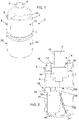
- Figure 1
- shows a perspective view of a device according to the invention,
- Figure 2
- shows a vertical section of the device of
fig. 1 , - Figure 3
- shows the device of
fig. 1 , - Figure 4
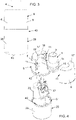
- shows an exploded view of the device of
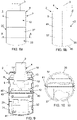
fig. 1 , - Figure 5
- shows in vertical section a piece of the casing of the device of
fig. 1 , - Figure 5b
- shows in plan the piece of
fig. 5a , - Figure 6a
- shows in vertical section the other piece of the casing of the device of
fig. 1 , - Figure 6b
- shows in plan the piece of
fig. 6a , - Figure 7a
- shows in vertical section the cap of the device of
fig. 1 , - Figure 7b
- shows a plan view of the cap of
fig. 7a , - Figure 8a
- shows a side view of a different embodiment of the closure device according to the invention,
- Figure 8b
- shows a different side view of the device of
fig. 8a , - Figure 9
- shows a vertical section of the device of
fig. 8a , - Figure 10
- shows a view obtained according to section XX of
fig. 8a , - Figure 11
- shows an exploded view of the device of
fig. 8a , - Figure 12
- shows it exploded in a different perspective view.
- As can be seen from the figures, the
device 2 to be applied in correspondence with theterminal portion 4 of apassage 3 of a fluid, in particular of gas or water or oil or other liquid in general, comprises at least twopieces mechanical engagement 11. In particular, said means 11 are configured to allow the joining of said pieces to each other around saidterminal portion 4 and thus define acasing 8 which is closed and which is fixed, preferably hanging, to saidterminal portion 4. Conveniently, said means 11 are configured to mechanically join the twopieces - Conveniently, said
casing 8 comprises inside achamber 9 in which theoutlet 10 of saidterminal portion 4 of thepassage 3 of a fluid is intended to be completely housed. Preferably, saidcasing 8 is hermetically closed and, therefore, thechamber 9 is thus completely isolated from theexternal environment 1. - In particular, the
device 2 is of the type intended to be installed in correspondence with aterminal portion 4 defined by the end of agas passage duct 3, preferably a gas delivery duct to a user, and/or defined by anattachment 13 defining agas passage 3 and connectable/connected to one end of a gas duct, for example to the gas delivery duct. Conveniently, thedevice 2 can also be installed in correspondence with the terminal portion of a duct for the passage of a liquid, in particular of water, preferably of a duct for delivering water to a user. - Conveniently, said at least two
pieces 5, 6 - once joined together by means of mechanical engagement means 11 - define saidcasing 8. In particular, the twopieces terminal portion 4 ofpassage 3. - Advantageously, as illustrated in the figures, said
casing 8 is defined by the union of twopieces - Conveniently, the chamber 9 - containing the
outlet mouth 10 of theterminal portion 4 of the fluid passage 3 - is entirely defined inside saidcasing 8. - Advantageously, the
terminal portion 4 comprises anattachment 13, which is externally threaded, and around which a connectingelement 14 is screwed, for example a nut, which is internally threaded. - Advantageously, to close the
outlet 10 of theterminal portion 4 of thepassage 3 of the fluid, aclosure plug 15 is provided which, preferably, is threaded externally and is screwed onto the connectingelement 14. In substance, the connectingelement 14 connects theclosing cap 15 to theoutlet 10 of theterminal portion 4 of thefluid passage 3. Preferably, agasket 16 is interposed between the connectingelement 14 and theclosure cap 15 which is suitably retained and compressed by screwing the closure cap to the connecting element. Preferably, the connectingelement 14 and/or theclosing cap 15 is made of metal. - Conveniently, therefore, inside the
chamber 9 defined by the union, around theterminal portion 4, of the twopieces closing cap 15 and the connectingelement 14 are also entirely housed, which therefore - a once the twopieces external environment 1 and, in particular, are not accessible from the outside. More in detail, advantageously, in this way, any access from the outside to the connectingelement 14 is prevented and, therefore, also the possibility of rotating it so as to be able to unscrew theclosing cap 15. - Advantageously, each of the two
pieces casing 8 having a substantially cylindrical or frusto-conical shape. - Conveniently, the two
pieces portions 17' and 17" - which, preferably together define the base of saidcasing 8 having a substantially cylindrical or frusto-conical shape - which are shaped in such a way as to define/delimit, following the union of said two pieces, a throughopening 18 of shape and size substantially corresponding to or slightly larger than the diameter of at least one cross section of theterminal portion 4 of thefluid passage 3, preferably of the diameter of the inlet section of saidattachment 13. Preferably, the throughopening 18 has a shape and size such as not to allow the insertion of a screwdriver inside saidopening 18 when the latter is crossed by said terminal portion, preventing or making it impossible any attempt to tamper with and remove thecasing 8 by forcing - for example by levering with a screwdriver - the separation between the twopieces - In particular, the two
pieces opening 18, of a substantially circular shape, for the insertion/crossing of theterminal portion 4, having a substantially circular section, ofpassage 3. - Conveniently, once the two
pieces terminal portion 4 of thefluid passage 3 so that said section passes through the throughopening 18, it can also be applied some sealing material in correspondence of any play present between the edges of the throughopening 18 and saidterminal portion 4, to thus define a hermetic seal of thechamber 9. - Advantageously, the two
pieces ribs 19 which, once the two pieces are mutually joined and thus define thechamber 9, develop inside the chamber itself and are configured to cooperate with the connecting element 14 (for example a nut) for its fixing and/or support, and are preferably configured to prevent rotation of thecasing 8, and therefore of the device, with respect to said connectingelement 14 and, preferably, to avoid the rotation of said connectingelement 14 inside thechamber 8. - Preferably, the
ribs 19 defined in each of the two pieces have a semianular conformation which, once the twopieces - Conveniently, a rib 19'is provided in each of the two
pieces element 14 can be inserted and locked between said rib and the base of thecasing 8 defined by theservings 17', 17". In particular, for this purpose, the connectingelement 14 rests on the rib 19'. - Conveniently, as said, said at least two
pieces pieces - The mechanical engagement means 11 are configured so that, once said mechanical engagement has been defined/activated, it can be removed - and therefore the
pieces pieces - Preferably, moreover, said first mechanical engagement means 11 are configured so as not to require any tools (for example screwdriver or wrench) to define/activate said engagement and, in particular, only require the application of a pushing action which can be exercised manually by the operator.
- Preferably, said first mechanical engagement means 11 are configured to define a snap-fit and/or press-fit engagement of corresponding members, provided in one of the two pieces, with/within suitable counter-members provided in the other piece. For example, said first engagement means 11 can comprise a
peg 20 which protrudes from the edges of the side walls of a piece 5 (seefig. 6a and 6b ) and which is configured to engage by interference within a correspondingcavity 21 provided in the other piece 6 (seefig. 7a and 7b ). Again, said first engagement means 11 may comprise atab 22, which protrudes from the edges of the side walls of a piece 6 (seefig. 7a and 7b ), and which is provided with an opening within which it engages by snap a correspondingprotuberance 23 provided on the side walls of the other piece 5 (seefig. 6a and 6b ). - Conveniently, the
device 2 also comprises acap 25 which internally delimits/defines afurther chamber 31. Conveniently, saidcap 25 is mechanically associable/associated with thecasing 8. Conveniently, saidfurther chamber 31 is fluidically and/or mechanically separated and is independent with respect to thefirst chamber 9. - Preferably, the
electronic board 32 and/or in general other electronic components of thedevice 2 are contained inside the cap. Therefore, preferably, theelectronic board 32 and/or in general the other electronic components are contained in acap 35 which is separate and distinct from thecasing 8 and from the external environment and, advantageously, this allows - in addition to protection from the external environment - also greater safety against tampering since, even once opened/once thecasing 8 has been removed, theelectronic board 32 and/or in general the other electronic components are not directly accessible. - Advantageously, therefore, the
device 2 comprises a first half-shell 12, which is defined by saidcasing 8, and a second half-shell 30, which is defined by thecap 25. - Advantageously, an
electronic board 32 is housed in saidfurther chamber 31, preferably a printed circuit board (in English "printed circuit board", called "PCB"). Preferably, saidelectronic board 32 comprises an electronic control and/or processing unit of saiddevice 2. Preferably, saidelectronic board 32 comprises an electronic unit (for example a microcontroller or microprocessor) for controlling and/or processing the received data by sensors with which said device can be provided. In particular, a software is loaded and executed in said electronic unit for the control/command of the electronic components of the device and/or to process and/or send out the data received from sensors installed in the device itself or connected to it. - Preferably, the
device 2 may be provided, for example: - an accelerometer, and/or
- a gyroscopic sensor or a magnetic field sensor or other sensor designed to detect changes in orientation.
- Preferably, the
device 2 can also comprise at least one sensor, for example of temperature and pressure, for detecting parameters of the fluid, and in particular of the gas, through thepassage 3. - Advantageously, the
device 2 can also comprise at least one sensor, for example temperature and/or pressure and/or humidity and/or acoustic noise, to detect parameters of the environment in which the device is installed. - Advantageously, the
device 2 can also comprise at least one sensor configured to detect the concentration of harmful gases (for example methane, propane or carbon monoxide) in the ambient air and/or inside the device itself. - Conveniently, said sensors, respectively for detecting parameters of the environment and/or of the gas and/or the concentration of harmful gases, are housed inside the
device 2 and are mounted and/or electronically connected to the electronic control and/or processing unit. - Inside said
further chamber 31, theelectronic board 32 is mounted in such a way as to be inclined/angled with respect to an axis parallel or perpendicular to the earth's gravitational field. - Advantageously, the
device 2 is provided with a unit for transmitting data to the outside, both at short range and at a distance to a remote unit. Conveniently, these data transmission means can be implemented and/or connected to saidelectronic board 32. Conveniently, said unit can be configured to act as a transceiver in order to transmit data to the outside and also to receive data (for example activation/command signals) from the outside. - Advantageously, inside said
further chamber 31 there is also housed at least one electricpower supply battery 33 which is electronically connected/mounted to/on saidelectronic board 32. - Advantageously, support means 34 are provided inside the cap 25 - for example defined by at least one protruding tab 34'from the internal side walls or from the bottom of said cap - to stably support the
battery 33 and/or theelectronic board 32. - Advantageously, a
seat 35 is defined inside the cap 25 - for example defined by portions protruding from the internal side walls and/or from the bottom of said cap - for theelectronic board 32 and/or thebattery 33. - Conveniently, the
cap 25 is joined to thecasing 8 by means ofmechanical connection 40 which, preferably, are also configured so that once said mechanical link is defined/activated, it can be removed - and therefore the cap and casing can be disjoint - only by breaking, at least in part, or damaging in a visible/evident and permanent way the pieces defining said cap and/or casing, and/or said means 40. In essence, said means 40 are configured to define a non-removable connection and thus joining the two half-shells in an irreversible way, if not causing the corresponding breakage or damage. - Conveniently, moreover, said mechanical connection means 40 are configured so as not to require any tool (for example screwdriver or wrench) to define/activate said engagement and, in particular, require only the application of a pushing action which can be exercised manually by the operator. Preferably, also the mechanical connection means 40 are configured to define a snap-fit and/or interference (press-fit) engagement of corresponding members, provided in the pieces defining the casing, with/within suitable counterparts members provided in the piece(s) defining the
cap 25. - Advantageously, the
casing 18 and thecap 25 are joined together - preferably in correspondence with anarea 43 of thecasing 18 which is opposite to that intended to be crossed by theterminal portion 4 of the fluid passage 3 - by mechanical coupling, preferably by form coupling. Conveniently, said mechanical coupling is defined by the conformation and sizing of the edges of thecasing 8 and thecap 25, which are also provided with said mechanical connection means 40. - Advantageously, in correspondence with the
coupling area 43 between thecasing 18 and thecap 25 also provides for the application of a sealant. In particular, the shape coupling between thecasing 18 and thecap 25 defines achannel 44 to be filled with a suitable sealing material. - Conveniently, the
cap 25 can be made in a single piece 36 (see embodiment offig. 1-7b ) or it can be made in twodistinct pieces 37, 38 (see embodiment offig. 8-12 ) which are provided with second mechanical engagement means 41 for their mutual union. Preferably, the second mechanical engagement means 41 for joining thepieces cap 25 are of the same type, described above, of said first mechanical engagement means 11 for joining thepieces casing 18. - Conveniently, also these second mechanical engagement means 41 are configured so that, once said mechanical engagement has been defined/activated, it can be removed - and therefore the two
pieces pieces - Preferably, the second half-
shell 30 defined by thecap 25 has a shape and dimensions substantially corresponding to those of the first half-shell 12 defined by thecasing 8. Preferably, said two half-shells - Preferably, the
device 2 is defined by the union of said first half-shell 12 (which is defined by the casing 8) and of said second half-shell 30 (which is defined by the cap 25) and, therefore, inside it comprises saidfirst chamber 9, in which theoutlet 10 of saidterminal portion 4 is completely housed, and a further/second chamber 31 in which theelectronic board 32 and, advantageously, also the electricpower supply battery 33 and/or the control unit are housed data transmission and/or reception. - Advantageously, the
first chamber 9 and thesecond chamber 31 are separate and independent from each other, i.e. they are not in mutual communication. In particular, for this purpose, a dividingwall 42 is provided which conveniently separates thecasing 8 and thecap 25 from each other. Advantageously, the dividingwall 42 can be integrated and defined in a single piece with one of said twopieces fig. 1-7b ) and/or can be made in a separate piece and distinct from all other pieces (see embodiment offig. 8-12 ) and/or it can be made by joining the twopieces envelope 8. - Conveniently, further support means 34 for the
battery 33 and/or for theelectronic board 32 can also be provided on the side of the dividingwall 42 intended to be turned towards the inside of thecap 25. For example, these means comprise a further fin 34' which cooperates with that provided in saidcap 25 to stably support theelectronic board 32 and/or thebattery 33. - Advantageously, the external surface of the bottom 45 of the cap 25 -
bottom 45 which is preferably defined on one side of thedevice 2 which is opposite to that in which said throughopening 18 is provided - it is shaped in such a way as to tilt laterally and/or unbalance when placed on a flat base. In particular, for this purpose, the external surface of the bottom 45 is concave and/or rounded, and preferably has the shape of the external surface of a spherical or elliptical cap. Conveniently, the external surface of the bottom 45 can have any shape which makes it unstable vertically and horizontally when in contact with a flat base. Advantageously, in this way, the device 2 - if it were removed - could not be stably positioned on a flat base, as it would necessarily fall and this would allow the sensors (for example a gyroscope and/or accelerometer), of which the device itself is provided, to identify a case of removal of thedevice 2 from theterminal portion 4 of thefluid passage 3, and thus to send a corresponding alarm. - Conveniently, in the embodiment of
figures 8 to 12 , a furtherintermediate piece 46 is also provided defining the dividingwall 42 which is then intended to be joined to the first casing 8 (which is obtained by joining twopieces 5, 6) and to the cap 25 (which inFigures 8 to 12 is obtained by joining twodistinct pieces first casing 8 and thecap 25 are joined/associated with each other by means of theintermediate piece 46 defining the dividingwall 42; suitably, in this case, the mechanical connection means 40 are configured to cause a connection between saidcasing 8 and the dividing wall 42 (preferably at one of its first faces) and, also, between thecap 25 and the dividing wall itself 42 (preferably in correspondence with its other face). - More in detail, also in this case, the mechanical connection means 40 are of the type described above. Preferably, said mechanical connection means 40 comprise male-type members (for example mushroom-shaped pins 49) provided in the dividing
wall 42 intended to engage by interlocking, preferably snap-fit, into corresponding female-type members (for example through holes 50) provided in thepieces envelope 8, or vice versa. Preferably, said connection means 40 comprise male-type members (for example folded sides 51) provided in thepiece 36 and/or in thepieces cap 25 and intended to engage by interlocking, preferably by snap action, into corresponding members of female type (for example through slots 52) provided in the dividingwall 42, or vice versa. - Conveniently, the
pieces envelope 8 and thepiece 36 and/or thepieces cap 25 and/or theintermediate piece 46 defining the dividingwall 42 are made of polymeric material, preferably of plastic. - The assembly of the
device 2 advantageously takes place according to the following method. First, theelectronic board 32 and thebattery 33 are inserted inside thecap 25 and the latter is then closed, preferably still in the factory, by applying to it thepiece 6 of thecasing 8 which is also provided with said dividing wall 42 (cf. embodiment offig. 1-7b ) or by applying to it theintermediate piece 46 defining the dividingwall 42 and then only one of the twopieces 5,6 (see embodiment offig. 8-12 ); suitably, in this way, already in the factory, a partially pre-assembled device is thus obtained (ie defined by thecap 25 and by only one of the two pieces defining the casing 8) which is then completed/closed only on site by joining, around theterminal portion 4 of the fluid passage 3 (preferably already closed by means of the closure cap 15), theother piece casing 8 to the partially pre-assembled device. - Conveniently, the activation of the
device 2 takes place on site, once it has been installed/closed around theterminal portion 4 of thefluid passage 3, by means of a magnet and by touching a predefined point provided in the cap. - Advantageously, as mentioned, once installed/closed around the
terminal portion 4 of thefluid passage 3, thecasing 8 and/or thecap 25 of thedevice 2 can be opened/disassembled/detached only causing breakage and/or damage in a visible and permanent way parts of the device itself. - From what has been said it is clear that the device according to the invention is particularly advantageous in that:
- it can be easily and quickly applied around the terminal portion of passage of a fluid (in particular of a gas or water or oil or other liquid in general); in particular, its pieces can be coupled together without requiring the use of any tools,
- defines an additional safety and sealing element (which is additional to the closing cap applied at the outlet of the gas passage) to prevent fluid (in particular gas or water) from escaping to the external environment safety,
- protects and prevents direct access to the terminal portion of the fluid passage (in particular gas or water), thus preventing its tampering,
- allows to detect any tampering carried out in correspondence with the terminal portion of the fluid passage (in particular gas or water) since, once applied around said section, it can only be removed by damaging it or causing its mechanical breakage, even partial, which is therefore easily visible,
- it is economical since it consists of a small number of components which are simple to manufacture and of low cost, and which can be easily produced in series.
Claims (15)
- Device (2) to be applied in correspondence with a passage (3) of a fluid, such as gas, water, oil or other liquid in general, in particular in correspondence with the terminal portion (4) of a passage (3) of a fluid, preferably of the type intended to act as an integrity seal of the closure (15) of said passage (3) and to isolate said closure (15) from the external environment, said device comprising at least two pieces (5, 6) which are provided with mechanical engagement means (11) configured to allow the mutual union of said at least two pieces (5, 6) around said terminal portion (4) and thus define a casing (8) which is fixed, preferably hanging, to said terminal portion (4), and in which:- said casing (8) comprises in its interior a chamber (9) in which is intended to be completely housed the outlet mouth (10) of the terminal portion (4) of said passage (3),- said mechanical engagement means (11) are obtained in said at least two pieces (5, 6) and are configured so that, once said mechanical engagement has been defined/activated and thus joined together said at least two pieces (5, 6), said at least two pieces (5,6) can be disunited only by breaking, at least in part, or by visibly and permanently damaging said at least two pieces (5, 6) and/or said mechanical engagement means (11), and characterized by comprising a cap (25) which can be associated and/or is associated with said casing (8), within said cap (25) a further chamber (31) being defined which is separate and independent from said chamber (9).
- Device according to claim 1, characterized in that said at least two pieces (5, 6) comprise corresponding portions (17', 17") which are shaped so as to define/delimit, following the union of said at least two pieces (5, 6), a through opening (18) having a shape and dimensions substantially corresponding to or slightly larger than the diameter of at least one cross section of the terminal portion (4) of said passage (3).
- Device according to one or more of the preceding claims, characterized in that said at least two pieces (5, 6) are internally provided with at least one rib (19, 19') configured to fix and/or support a connecting element (14) configured to constrain a closure cap (15) to the outlet (10) of the terminal portion (4) of said passage (3), said chamber (9) being configured to house said connecting element (14) inside it and said closing cap (15).
- Device according to one or more of the preceding claims, characterized in that said further chamber (31) contains an electronic board (32) and/or an electric power supply battery (33).
- Device according to the preceding claim, characterized in that inside the cap (25)- a seat is defined for the electronic board (32) and/or said battery (33), and/or- support means (34) are provided for stably supporting said electronic board (32) and/or said battery (33).
- Device according to claims 4 or 5, characterized in that, inside said further chamber (31), the electronic board (32) is mounted so as to be inclined/angled with respect to an axis parallel or perpendicular to the terrestrial gravitational field.
- Device according to one or more of the preceding claims, characterized in that it comprises mechanical connection means (40) for joining said cap (25) to said casing (8), and in that said mechanical connection means ( 40) are obtained in said pieces (5, 6, 36, 37, 38) defining said casing (8) and said cap (25), or in an intermediate connecting piece (46) of said casing (8) to said cap (25) and are configured so that, once said mechanical connection has been defined/activated and thus joined together the pieces (5, 6, 36, 37, 38), the pieces themselves can be disunited only by breaking, at least in part, or by visibly and permanently damaging said pieces (5, 6, 36, 37, 38) and/or said mechanical connection means (40).
- Device according to one or more of the preceding claims, characterized in that, between said casing (8) and said hood (25), a dividing wall (42) is interposed which is made in a single piece with one of the pieces (5, 6) defining said casing (8) and/or is made in an intermediate piece (46) separate from the pieces defining said casing (8) and said cap (25), and/or is defined by the union of the pieces defining said first casing (8).
- Device according to one or more of the preceding claims, characterized in that said casing (8) defines a first half-shell (12) and said cap (25) defines a second half-shell (30) and in that said first half-shell (12) and said second half-shell (30) have a substantially corresponding shape and size.
- Device according to one or more of the preceding claims, characterized in that said cap (25) is made in a single piece (36) or in at least two pieces (37, 38) provided with second mechanical engagement means (41) configured to allow the mutual union of said at least two pieces (37, 38) to thus define said cap (25).
- Device according to one or more of the preceding claims, characterized in that the bottom outer surface (45) of the device itself, which is preferably defined by the cap bottom (25), is shaped so as to incline laterally and/or overreach when placed on a flat base.
- Device according to one or more of the preceding claims, characterized in that all the engagement means (11, 40, 41) for joining the pieces (5, 6, 36, 37, 38) defining said casing (8) and/or said cap (25), and the connection means (40) for joining said casing (8) to said cap (25) are configured so as not to require any external and additional fastening element with respect to the pieces to be joined and so as not to require any tools to define/activate said engagement and/or link.
- Device according to one or more of the preceding claims, characterized in that all the engagement means (11, 40, 41) for joining the pieces (5, 6, 36, 37, 38) defining said casing (8) and/or said cap (25), and the connecting means (40) for joining said casing (8) to said cap (25) are configured to define a snap-fit and/or to interference (press-fit) of corresponding members, provided in one piece to be joined, with/within suitable counter-members provided in the other piece to be joined.
- Device according to one or more of the preceding claims, characterized in that said casing (8) defined by the union of said at least two pieces (5, 6) is hermetically closed, said chamber (9) thus being completely isolated from the environment external (1).
- Device according to one or more of the preceding claims, characterized by the fact that the shape coupling between the casing (18) and the cap (25) defines a channel (44) designed to be filled with a sealant material.
Applications Claiming Priority (1)
| Application Number | Priority Date | Filing Date | Title |
|---|---|---|---|
| IT102019000022182A IT201900022182A1 (en) | 2019-11-26 | 2019-11-26 | Device to be applied in correspondence with a gas passage. |
Publications (2)
| Publication Number | Publication Date |
|---|---|
| EP3828458A1 EP3828458A1 (en) | 2021-06-02 |
| EP3828458B1 true EP3828458B1 (en) | 2022-08-31 |
Family
ID=69904062
Family Applications (1)
| Application Number | Title | Priority Date | Filing Date |
|---|---|---|---|
| EP20209703.6A Active EP3828458B1 (en) | 2019-11-26 | 2020-11-25 | Device to be applied in correspondence of a passage of a fluid |
Country Status (3)
| Country | Link |
|---|---|
| EP (1) | EP3828458B1 (en) |
| HU (1) | HUE060338T2 (en) |
| IT (1) | IT201900022182A1 (en) |
Family Cites Families (4)
| Publication number | Priority date | Publication date | Assignee | Title |
|---|---|---|---|---|
| DE3042839C2 (en) * | 1980-11-13 | 1983-03-31 | Container Corporation of America, 60670 Chicago, Ill. | Sealing cap |
| FR2642814B1 (en) * | 1989-02-08 | 1991-05-10 | Labinal | RING OF CLOSING OF RINGS |
| DE112014006048T5 (en) * | 2013-12-25 | 2016-09-08 | Nitta Corporation | connector cover |
| EP3633135B1 (en) * | 2018-10-02 | 2020-09-02 | Vallourec Oil And Gas France | Protective device for a male end portion of a steel tube intented for use in a tubular hydrocarbon working string |
-
2019
- 2019-11-26 IT IT102019000022182A patent/IT201900022182A1/en unknown
-
2020
- 2020-11-25 HU HUE20209703A patent/HUE060338T2/en unknown
- 2020-11-25 EP EP20209703.6A patent/EP3828458B1/en active Active
Also Published As
| Publication number | Publication date |
|---|---|
| IT201900022182A1 (en) | 2021-05-26 |
| EP3828458A1 (en) | 2021-06-02 |
| HUE060338T2 (en) | 2023-02-28 |
Similar Documents
| Publication | Publication Date | Title |
|---|---|---|
| US8455759B2 (en) | Inlet cover and adapter assembly for electrical components | |
| US4471982A (en) | Tamper indicating cover for a gas meter | |
| US4422674A (en) | Tamper proof gas meter | |
| KR101732913B1 (en) | Apparatus for communication wireless between inside of manhole and outside of manhole | |
| WO2006044110A2 (en) | Improved valve cover | |
| EP3828458A1 (en) | Device to be applied in correspondence of a passage of a fluid | |
| KR101799490B1 (en) | Explosion-proof junction box | |
| KR101006544B1 (en) | Closing Seal Cap | |
| US10287862B2 (en) | Stuffing box leak containment apparatus | |
| CN217358841U (en) | Pipeline pressure on-line monitoring device | |
| EP3828515B1 (en) | Device to be applied in correspondence of a passage of a fluid | |
| KR100994798B1 (en) | Built in type gas cutoff apparatus | |
| WO2009154367A2 (en) | Automatic gas shut-off device | |
| CN204065195U (en) | Electric energy meter case body structure | |
| US6852922B2 (en) | Apparatus and method for sealing a conduit | |
| KR20090001627U (en) | Gas valve connection seal | |
| KR102582477B1 (en) | Integrated explosion-proof sealing fitting device and its installation method | |
| CN214222136U (en) | Go out wall valve and gas heater | |
| CN208569823U (en) | A kind of protection against electric shock structure of fire detector | |
| US6883366B1 (en) | Tamper resistant vapor sensor method and system | |
| CA2656973A1 (en) | Heating apparatus for installation on rooftop end of sewer vent pipe | |
| CN223427988U (en) | Block terminal cable import and export plugging device | |
| KR200439533Y1 (en) | Locking device of on / off valve | |
| CN210517693U (en) | High-altitude outdoor terminal box optical fiber cable plugging device | |
| KR200294503Y1 (en) | A device preventing steal water for a water gauge meter |
Legal Events
| Date | Code | Title | Description |
|---|---|---|---|
| PUAI | Public reference made under article 153(3) epc to a published international application that has entered the european phase |
Free format text: ORIGINAL CODE: 0009012 |
|
| STAA | Information on the status of an ep patent application or granted ep patent |
Free format text: STATUS: THE APPLICATION HAS BEEN PUBLISHED |
|
| AK | Designated contracting states |
Kind code of ref document: A1 Designated state(s): AL AT BE BG CH CY CZ DE DK EE ES FI FR GB GR HR HU IE IS IT LI LT LU LV MC MK MT NL NO PL PT RO RS SE SI SK SM TR |
|
| STAA | Information on the status of an ep patent application or granted ep patent |
Free format text: STATUS: REQUEST FOR EXAMINATION WAS MADE |
|
| 17P | Request for examination filed |
Effective date: 20211125 |
|
| RBV | Designated contracting states (corrected) |
Designated state(s): AL AT BE BG CH CY CZ DE DK EE ES FI FR GB GR HR HU IE IS IT LI LT LU LV MC MK MT NL NO PL PT RO RS SE SI SK SM TR |
|
| GRAP | Despatch of communication of intention to grant a patent |
Free format text: ORIGINAL CODE: EPIDOSNIGR1 |
|
| STAA | Information on the status of an ep patent application or granted ep patent |
Free format text: STATUS: GRANT OF PATENT IS INTENDED |
|
| RIC1 | Information provided on ipc code assigned before grant |
Ipc: B65D 55/02 20060101ALI20220307BHEP Ipc: F16L 57/00 20060101AFI20220307BHEP |
|
| INTG | Intention to grant announced |
Effective date: 20220411 |
|
| GRAS | Grant fee paid |
Free format text: ORIGINAL CODE: EPIDOSNIGR3 |
|
| GRAA | (expected) grant |
Free format text: ORIGINAL CODE: 0009210 |
|
| STAA | Information on the status of an ep patent application or granted ep patent |
Free format text: STATUS: THE PATENT HAS BEEN GRANTED |
|
| AK | Designated contracting states |
Kind code of ref document: B1 Designated state(s): AL AT BE BG CH CY CZ DE DK EE ES FI FR GB GR HR HU IE IS IT LI LT LU LV MC MK MT NL NO PL PT RO RS SE SI SK SM TR |
|
| REG | Reference to a national code |
Ref country code: CH Ref legal event code: EP Ref country code: GB Ref legal event code: FG4D |
|
| REG | Reference to a national code |
Ref country code: AT Ref legal event code: REF Ref document number: 1515529 Country of ref document: AT Kind code of ref document: T Effective date: 20220915 Ref country code: DE Ref legal event code: R096 Ref document number: 602020004829 Country of ref document: DE |
|
| REG | Reference to a national code |
Ref country code: IE Ref legal event code: FG4D |
|
| REG | Reference to a national code |
Ref country code: LT Ref legal event code: MG9D |
|
| REG | Reference to a national code |
Ref country code: NL Ref legal event code: MP Effective date: 20220831 |
|
| PG25 | Lapsed in a contracting state [announced via postgrant information from national office to epo] |
Ref country code: SE Free format text: LAPSE BECAUSE OF FAILURE TO SUBMIT A TRANSLATION OF THE DESCRIPTION OR TO PAY THE FEE WITHIN THE PRESCRIBED TIME-LIMIT Effective date: 20220831 Ref country code: RS Free format text: LAPSE BECAUSE OF FAILURE TO SUBMIT A TRANSLATION OF THE DESCRIPTION OR TO PAY THE FEE WITHIN THE PRESCRIBED TIME-LIMIT Effective date: 20220831 Ref country code: NO Free format text: LAPSE BECAUSE OF FAILURE TO SUBMIT A TRANSLATION OF THE DESCRIPTION OR TO PAY THE FEE WITHIN THE PRESCRIBED TIME-LIMIT Effective date: 20221130 Ref country code: LV Free format text: LAPSE BECAUSE OF FAILURE TO SUBMIT A TRANSLATION OF THE DESCRIPTION OR TO PAY THE FEE WITHIN THE PRESCRIBED TIME-LIMIT Effective date: 20220831 Ref country code: LT Free format text: LAPSE BECAUSE OF FAILURE TO SUBMIT A TRANSLATION OF THE DESCRIPTION OR TO PAY THE FEE WITHIN THE PRESCRIBED TIME-LIMIT Effective date: 20220831 Ref country code: FI Free format text: LAPSE BECAUSE OF FAILURE TO SUBMIT A TRANSLATION OF THE DESCRIPTION OR TO PAY THE FEE WITHIN THE PRESCRIBED TIME-LIMIT Effective date: 20220831 |
|
| REG | Reference to a national code |
Ref country code: AT Ref legal event code: MK05 Ref document number: 1515529 Country of ref document: AT Kind code of ref document: T Effective date: 20220831 |
|
| PG25 | Lapsed in a contracting state [announced via postgrant information from national office to epo] |
Ref country code: PL Free format text: LAPSE BECAUSE OF FAILURE TO SUBMIT A TRANSLATION OF THE DESCRIPTION OR TO PAY THE FEE WITHIN THE PRESCRIBED TIME-LIMIT Effective date: 20220831 Ref country code: IS Free format text: LAPSE BECAUSE OF FAILURE TO SUBMIT A TRANSLATION OF THE DESCRIPTION OR TO PAY THE FEE WITHIN THE PRESCRIBED TIME-LIMIT Effective date: 20221231 Ref country code: HR Free format text: LAPSE BECAUSE OF FAILURE TO SUBMIT A TRANSLATION OF THE DESCRIPTION OR TO PAY THE FEE WITHIN THE PRESCRIBED TIME-LIMIT Effective date: 20220831 Ref country code: GR Free format text: LAPSE BECAUSE OF FAILURE TO SUBMIT A TRANSLATION OF THE DESCRIPTION OR TO PAY THE FEE WITHIN THE PRESCRIBED TIME-LIMIT Effective date: 20221201 |
|
| PGFP | Annual fee paid to national office [announced via postgrant information from national office to epo] |
Ref country code: HU Payment date: 20221125 Year of fee payment: 3 |
|
| REG | Reference to a national code |
Ref country code: HU Ref legal event code: AG4A Ref document number: E060338 Country of ref document: HU |
|
| PG25 | Lapsed in a contracting state [announced via postgrant information from national office to epo] |
Ref country code: SM Free format text: LAPSE BECAUSE OF FAILURE TO SUBMIT A TRANSLATION OF THE DESCRIPTION OR TO PAY THE FEE WITHIN THE PRESCRIBED TIME-LIMIT Effective date: 20220831 Ref country code: RO Free format text: LAPSE BECAUSE OF FAILURE TO SUBMIT A TRANSLATION OF THE DESCRIPTION OR TO PAY THE FEE WITHIN THE PRESCRIBED TIME-LIMIT Effective date: 20220831 Ref country code: PT Free format text: LAPSE BECAUSE OF FAILURE TO SUBMIT A TRANSLATION OF THE DESCRIPTION OR TO PAY THE FEE WITHIN THE PRESCRIBED TIME-LIMIT Effective date: 20230102 Ref country code: ES Free format text: LAPSE BECAUSE OF FAILURE TO SUBMIT A TRANSLATION OF THE DESCRIPTION OR TO PAY THE FEE WITHIN THE PRESCRIBED TIME-LIMIT Effective date: 20220831 Ref country code: DK Free format text: LAPSE BECAUSE OF FAILURE TO SUBMIT A TRANSLATION OF THE DESCRIPTION OR TO PAY THE FEE WITHIN THE PRESCRIBED TIME-LIMIT Effective date: 20220831 Ref country code: CZ Free format text: LAPSE BECAUSE OF FAILURE TO SUBMIT A TRANSLATION OF THE DESCRIPTION OR TO PAY THE FEE WITHIN THE PRESCRIBED TIME-LIMIT Effective date: 20220831 Ref country code: AT Free format text: LAPSE BECAUSE OF FAILURE TO SUBMIT A TRANSLATION OF THE DESCRIPTION OR TO PAY THE FEE WITHIN THE PRESCRIBED TIME-LIMIT Effective date: 20220831 |
|
| PG25 | Lapsed in a contracting state [announced via postgrant information from national office to epo] |
Ref country code: SK Free format text: LAPSE BECAUSE OF FAILURE TO SUBMIT A TRANSLATION OF THE DESCRIPTION OR TO PAY THE FEE WITHIN THE PRESCRIBED TIME-LIMIT Effective date: 20220831 Ref country code: EE Free format text: LAPSE BECAUSE OF FAILURE TO SUBMIT A TRANSLATION OF THE DESCRIPTION OR TO PAY THE FEE WITHIN THE PRESCRIBED TIME-LIMIT Effective date: 20220831 |
|
| REG | Reference to a national code |
Ref country code: DE Ref legal event code: R119 Ref document number: 602020004829 Country of ref document: DE Ref country code: DE Ref legal event code: R097 Ref document number: 602020004829 Country of ref document: DE |
|
| PG25 | Lapsed in a contracting state [announced via postgrant information from national office to epo] |
Ref country code: NL Free format text: LAPSE BECAUSE OF FAILURE TO SUBMIT A TRANSLATION OF THE DESCRIPTION OR TO PAY THE FEE WITHIN THE PRESCRIBED TIME-LIMIT Effective date: 20220831 Ref country code: MC Free format text: LAPSE BECAUSE OF FAILURE TO SUBMIT A TRANSLATION OF THE DESCRIPTION OR TO PAY THE FEE WITHIN THE PRESCRIBED TIME-LIMIT Effective date: 20220831 Ref country code: AL Free format text: LAPSE BECAUSE OF FAILURE TO SUBMIT A TRANSLATION OF THE DESCRIPTION OR TO PAY THE FEE WITHIN THE PRESCRIBED TIME-LIMIT Effective date: 20220831 |
|
| PLBE | No opposition filed within time limit |
Free format text: ORIGINAL CODE: 0009261 |
|
| STAA | Information on the status of an ep patent application or granted ep patent |
Free format text: STATUS: NO OPPOSITION FILED WITHIN TIME LIMIT |
|
| REG | Reference to a national code |
Ref country code: BE Ref legal event code: MM Effective date: 20221130 |
|
| 26N | No opposition filed |
Effective date: 20230601 |
|
| PG25 | Lapsed in a contracting state [announced via postgrant information from national office to epo] |
Ref country code: SI Free format text: LAPSE BECAUSE OF FAILURE TO SUBMIT A TRANSLATION OF THE DESCRIPTION OR TO PAY THE FEE WITHIN THE PRESCRIBED TIME-LIMIT Effective date: 20220831 Ref country code: LU Free format text: LAPSE BECAUSE OF NON-PAYMENT OF DUE FEES Effective date: 20221125 |
|
| PG25 | Lapsed in a contracting state [announced via postgrant information from national office to epo] |
Ref country code: IE Free format text: LAPSE BECAUSE OF NON-PAYMENT OF DUE FEES Effective date: 20221125 Ref country code: DE Free format text: LAPSE BECAUSE OF NON-PAYMENT OF DUE FEES Effective date: 20230601 |
|
| PG25 | Lapsed in a contracting state [announced via postgrant information from national office to epo] |
Ref country code: FR Free format text: LAPSE BECAUSE OF NON-PAYMENT OF DUE FEES Effective date: 20221130 Ref country code: BE Free format text: LAPSE BECAUSE OF NON-PAYMENT OF DUE FEES Effective date: 20221130 |
|
| PG25 | Lapsed in a contracting state [announced via postgrant information from national office to epo] |
Ref country code: CY Free format text: LAPSE BECAUSE OF FAILURE TO SUBMIT A TRANSLATION OF THE DESCRIPTION OR TO PAY THE FEE WITHIN THE PRESCRIBED TIME-LIMIT Effective date: 20220831 |
|
| PG25 | Lapsed in a contracting state [announced via postgrant information from national office to epo] |
Ref country code: MK Free format text: LAPSE BECAUSE OF FAILURE TO SUBMIT A TRANSLATION OF THE DESCRIPTION OR TO PAY THE FEE WITHIN THE PRESCRIBED TIME-LIMIT Effective date: 20220831 Ref country code: IT Free format text: LAPSE BECAUSE OF FAILURE TO SUBMIT A TRANSLATION OF THE DESCRIPTION OR TO PAY THE FEE WITHIN THE PRESCRIBED TIME-LIMIT Effective date: 20220831 |
|
| PG25 | Lapsed in a contracting state [announced via postgrant information from national office to epo] |
Ref country code: TR Free format text: LAPSE BECAUSE OF FAILURE TO SUBMIT A TRANSLATION OF THE DESCRIPTION OR TO PAY THE FEE WITHIN THE PRESCRIBED TIME-LIMIT Effective date: 20220831 |
|
| REG | Reference to a national code |
Ref country code: CH Ref legal event code: PL |
|
| PG25 | Lapsed in a contracting state [announced via postgrant information from national office to epo] |
Ref country code: CH Free format text: LAPSE BECAUSE OF NON-PAYMENT OF DUE FEES Effective date: 20231130 |
|
| PG25 | Lapsed in a contracting state [announced via postgrant information from national office to epo] |
Ref country code: CH Free format text: LAPSE BECAUSE OF NON-PAYMENT OF DUE FEES Effective date: 20231130 Ref country code: BG Free format text: LAPSE BECAUSE OF FAILURE TO SUBMIT A TRANSLATION OF THE DESCRIPTION OR TO PAY THE FEE WITHIN THE PRESCRIBED TIME-LIMIT Effective date: 20220831 |
|
| PG25 | Lapsed in a contracting state [announced via postgrant information from national office to epo] |
Ref country code: HU Free format text: LAPSE BECAUSE OF NON-PAYMENT OF DUE FEES Effective date: 20231126 |
|
| PG25 | Lapsed in a contracting state [announced via postgrant information from national office to epo] |
Ref country code: MT Free format text: LAPSE BECAUSE OF FAILURE TO SUBMIT A TRANSLATION OF THE DESCRIPTION OR TO PAY THE FEE WITHIN THE PRESCRIBED TIME-LIMIT Effective date: 20220831 |
|
| GBPC | Gb: european patent ceased through non-payment of renewal fee |
Effective date: 20241125 |
|
| PG25 | Lapsed in a contracting state [announced via postgrant information from national office to epo] |
Ref country code: GB Free format text: LAPSE BECAUSE OF NON-PAYMENT OF DUE FEES Effective date: 20241125 |