EP3828456B1 - Hose connector - Google Patents
Hose connector Download PDFInfo
- Publication number
- EP3828456B1 EP3828456B1 EP20209816.6A EP20209816A EP3828456B1 EP 3828456 B1 EP3828456 B1 EP 3828456B1 EP 20209816 A EP20209816 A EP 20209816A EP 3828456 B1 EP3828456 B1 EP 3828456B1
- Authority
- EP
- European Patent Office
- Prior art keywords
- hose
- connector
- thread
- inner part
- fitting
- Prior art date
- Legal status (The legal status is an assumption and is not a legal conclusion. Google has not performed a legal analysis and makes no representation as to the accuracy of the status listed.)
- Active
Links
Images

Classifications
-
- F—MECHANICAL ENGINEERING; LIGHTING; HEATING; WEAPONS; BLASTING
- F16—ENGINEERING ELEMENTS AND UNITS; GENERAL MEASURES FOR PRODUCING AND MAINTAINING EFFECTIVE FUNCTIONING OF MACHINES OR INSTALLATIONS; THERMAL INSULATION IN GENERAL
- F16L—PIPES; JOINTS OR FITTINGS FOR PIPES; SUPPORTS FOR PIPES, CABLES OR PROTECTIVE TUBING; MEANS FOR THERMAL INSULATION IN GENERAL
- F16L37/00—Couplings of the quick-acting type
- F16L37/50—Couplings of the quick-acting type adjustable; allowing movement of the parts joined
- F16L37/53—Couplings of the quick-acting type adjustable; allowing movement of the parts joined allowing adjustment or movement only about the axis of one pipe
-
- B—PERFORMING OPERATIONS; TRANSPORTING
- B01—PHYSICAL OR CHEMICAL PROCESSES OR APPARATUS IN GENERAL
- B01L—CHEMICAL OR PHYSICAL LABORATORY APPARATUS FOR GENERAL USE
- B01L3/00—Containers or dishes for laboratory use, e.g. laboratory glassware; Droppers
- B01L3/56—Labware specially adapted for transferring fluids
- B01L3/561—Tubes; Conduits
-
- B—PERFORMING OPERATIONS; TRANSPORTING
- B01—PHYSICAL OR CHEMICAL PROCESSES OR APPARATUS IN GENERAL
- B01L—CHEMICAL OR PHYSICAL LABORATORY APPARATUS FOR GENERAL USE
- B01L3/00—Containers or dishes for laboratory use, e.g. laboratory glassware; Droppers
- B01L3/56—Labware specially adapted for transferring fluids
- B01L3/563—Joints or fittings; Separable fluid transfer means to transfer fluids between at least two containers, e.g. connectors
-
- F—MECHANICAL ENGINEERING; LIGHTING; HEATING; WEAPONS; BLASTING
- F16—ENGINEERING ELEMENTS AND UNITS; GENERAL MEASURES FOR PRODUCING AND MAINTAINING EFFECTIVE FUNCTIONING OF MACHINES OR INSTALLATIONS; THERMAL INSULATION IN GENERAL
- F16L—PIPES; JOINTS OR FITTINGS FOR PIPES; SUPPORTS FOR PIPES, CABLES OR PROTECTIVE TUBING; MEANS FOR THERMAL INSULATION IN GENERAL
- F16L15/00—Screw-threaded joints; Forms of screw-threads for such joints
- F16L15/08—Screw-threaded joints; Forms of screw-threads for such joints with supplementary elements
-
- F—MECHANICAL ENGINEERING; LIGHTING; HEATING; WEAPONS; BLASTING
- F16—ENGINEERING ELEMENTS AND UNITS; GENERAL MEASURES FOR PRODUCING AND MAINTAINING EFFECTIVE FUNCTIONING OF MACHINES OR INSTALLATIONS; THERMAL INSULATION IN GENERAL
- F16L—PIPES; JOINTS OR FITTINGS FOR PIPES; SUPPORTS FOR PIPES, CABLES OR PROTECTIVE TUBING; MEANS FOR THERMAL INSULATION IN GENERAL
- F16L37/00—Couplings of the quick-acting type
- F16L37/08—Couplings of the quick-acting type in which the connection between abutting or axially overlapping ends is maintained by locking members
- F16L37/084—Couplings of the quick-acting type in which the connection between abutting or axially overlapping ends is maintained by locking members combined with automatic locking
- F16L37/092—Couplings of the quick-acting type in which the connection between abutting or axially overlapping ends is maintained by locking members combined with automatic locking by means of elements wedged between the pipe and the frusto-conical surface of the body of the connector
-
- F—MECHANICAL ENGINEERING; LIGHTING; HEATING; WEAPONS; BLASTING
- F16—ENGINEERING ELEMENTS AND UNITS; GENERAL MEASURES FOR PRODUCING AND MAINTAINING EFFECTIVE FUNCTIONING OF MACHINES OR INSTALLATIONS; THERMAL INSULATION IN GENERAL
- F16L—PIPES; JOINTS OR FITTINGS FOR PIPES; SUPPORTS FOR PIPES, CABLES OR PROTECTIVE TUBING; MEANS FOR THERMAL INSULATION IN GENERAL
- F16L47/00—Connecting arrangements or other fittings specially adapted to be made of plastics or to be used with pipes made of plastics
- F16L47/16—Screw-threaded joints
-
- A—HUMAN NECESSITIES
- A61—MEDICAL OR VETERINARY SCIENCE; HYGIENE
- A61M—DEVICES FOR INTRODUCING MEDIA INTO, OR ONTO, THE BODY; DEVICES FOR TRANSDUCING BODY MEDIA OR FOR TAKING MEDIA FROM THE BODY; DEVICES FOR PRODUCING OR ENDING SLEEP OR STUPOR
- A61M39/00—Tubes, tube connectors, tube couplings, valves, access sites or the like, specially adapted for medical use
- A61M39/10—Tube connectors; Tube couplings
- A61M2039/1038—Union screw connectors, e.g. hollow screw or sleeve having external threads
-
- B—PERFORMING OPERATIONS; TRANSPORTING
- B01—PHYSICAL OR CHEMICAL PROCESSES OR APPARATUS IN GENERAL
- B01L—CHEMICAL OR PHYSICAL LABORATORY APPARATUS FOR GENERAL USE
- B01L2200/00—Solutions for specific problems relating to chemical or physical laboratory apparatus
- B01L2200/02—Adapting objects or devices to another
- B01L2200/023—Adapting objects or devices to another adapted for different sizes of tubes, tips or container
-
- B—PERFORMING OPERATIONS; TRANSPORTING
- B01—PHYSICAL OR CHEMICAL PROCESSES OR APPARATUS IN GENERAL
- B01L—CHEMICAL OR PHYSICAL LABORATORY APPARATUS FOR GENERAL USE
- B01L2200/00—Solutions for specific problems relating to chemical or physical laboratory apparatus
- B01L2200/02—Adapting objects or devices to another
- B01L2200/025—Align devices or objects to ensure defined positions relative to each other
-
- B—PERFORMING OPERATIONS; TRANSPORTING
- B01—PHYSICAL OR CHEMICAL PROCESSES OR APPARATUS IN GENERAL
- B01L—CHEMICAL OR PHYSICAL LABORATORY APPARATUS FOR GENERAL USE
- B01L2200/00—Solutions for specific problems relating to chemical or physical laboratory apparatus
- B01L2200/02—Adapting objects or devices to another
- B01L2200/026—Fluid interfacing between devices or objects, e.g. connectors, inlet details
Definitions
- the invention relates to a hose connection for tubes of automated analyser systems transferring mediums like liquid fluids.
- Automated analyser systems for use in clinical diagnostics and life sciences are produced by a number of companies.
- STRATEC ® SE Birkenfeld, Germany
- the most common manner for connecting hoses that transfer liquids are screw couplings.
- the parts which are connect are usually made of fluoropolymers such as PTFE or FEP, in particular in the field of analysis and medical technology. Such materials provide media resistance and pressure resistance. Due to their strong creep behavior and their relatively high hardness, these hoses cannot simply be put together for connection. Special fitting screws are used for such couplings.
- a tube's or hose's end is reshaped, or a flange is formed at its end using heat and pressure in order to obtain a sealed connection between the fitting and its counterpart.
- a molded flange seals between the front of the fitting and the threat root of the counterpart.
- a ring may be arranged between flange and fitting for uncoupling torsion forces that may occur during tightening of fitting and its counterpart.
- a disadvantage of this method is that the process of flange forming requires a number of auxiliary devices or tools. On the one hand, a holding device for the hose is needed and on the other hand the actual forming tool. Often, a heated mandrel is used, which heats the tube before forming. In addition, just with this type of screw often chipped items made of materials such as PEEK are used. Especially the assembly and the parts production make this type of connection costly. In addition, the forming of such a hose connection requires some experience in the assembly and is therefore not too user friendly. The method applies only to the hard fluoropolymer tubing. Thermoplastic elastomers cannot be reshaped to the required precision due to their elasticity and lower Shore hardness.
- An alternative to reshaping the end of a tube or hose is an insert that is a gasket with a cylindric hose connection and a ring for rotational decoupling.
- the fitting screw is pushed over the tube or hose followed by the ring and finally, the insert is introduced into the tube or hose.
- the sealing flange consists of a disc with a dome. This dome is inserted with slight excess in the hose. Due to the high hardness of the hose and the small size of the components, this results in an increased effort in the assembly.
- By inserting the dome in the hose whose cross-section is reduced which results in a flow resistance in the system. Depending on the flow rate, the fluid is compressed in front of the dome and undergoes an expansion behind the cross-sectional reduction, which can lead to undesired turbulence.
- Another possibility for sealing is to use an elastomer seal that is put over the tube's end, so that sealing takes place at the outside of the tube.
- the tightness to the hose and the actual sealing seat in the counterpart is made only by an elastomeric element. Just the tightness to the counterpart is thus always dependent on the installation. If the sealing part is pushed too far onto the hose, there is no connection between the elastomer and the counterpart. The tightness is therefore no longer present.
- the assembly is difficult on the one hand due to the specified tolerance problem and on the other hand because of the required assembly forces. It is recommended to use a mounting device. This increases the effort and thus the costs.
- this connection technique is limited to the rather hard fluoropolymer hoses. Sliding the connector onto softer hoses would reduce its cross section. In addition, it is questionable whether the seal part can ever postpone due to the higher friction values.
- a very simple method for connecting tubes with a Shore hardness below 85 A is the use of a so-called barb connector, where the tube is put over a mandrel with a greater outer diameter than the inner diameter of the tube.
- the mandrel shall be mushroom-shaped. This is the most common, tool-free way of connecting hoses. It is widely used when it comes to fluid transport in the low-pressure range. The hose is only put over the counterpart. The resulting, in places multiple line contact between fitting and hose guarantees the seal between the two partners. However, just this slipping also has some disadvantages. On the one hand, depending on the hardness of the hose and the selected excess between fitting and hose, the assembly is difficult.
- connection With increasing excess or increasing hardness, the contact forces, which are usually applied manually, increase sharply. To counteract, the excess can be reduced with increasing the hose hardness or wall thickness. As the excess decreases, however, the compressive strength of the overall connection also decreases. For pressure applications and the use of highly pulsating pumps, this connection may have an undefined instability. The fitting will be screwed into a counterpart. If the hose is connected to the fitting prior to screwing the fitting into its counterpart, the connection may loosen due to tensions in the hoses resulting from twisting them.
- Luer lock For a quick connection and release a so-called Luer lock is very often used in medical devices. Such a connection is based on two coupling pieces which are connected and sealed only by a self-locking cone. In the Lock variant results from an external thread, which can be closed by a 90 ° - rotation, an additional closure of a pulling apart of the conical connection and thus prevents leaks.
- a disadvantage of a Luer lock is that the partners of the lock are twisted against each other with the result that the hose is twisted in its elastic range. Under certain circumstances, this can mean that the connection loosens itself due to the elasticity of the hose and that leaks can occur.
- the locking thread of the Luer Lock coupling is designed for an ergonomically comfortable 1 ⁇ 4 turn.
- This large thread pitch reduces the self-locking of the thread to a significantly low level. This has the consequence that this locking thread reliably locked only with a firmly connected Luer cone and this lock also holds.
- the friction of the Luer cones is eliminated.
- the torsional coupled union nut can only jam due to the adhesion between the screw and nut threads (self-locking). However, since this is reduced by the large pitch there is always the risk of an independent release of the locking thread. In this case, the holding force consists only of the two inserted Luer cone.
- Published U.S. Patent Application No. US 2018/0128405 A1 relates to a single action push to connect fitting for a conduit such as tube or pipe.
- the fitting includes a first fitting component and a second fitting component that are joined or assembled together to form a fitting assembly.
- the fitting assembly includes a conduit seal device and a conduit retaining device.
- a conduit may be manually or otherwise inserted into the assembled fitting assembly with a single axial movement and be retained and sealed without the need for further action or movement of the fitting components.
- a disadvantage of a fitting assembly according to this publication is that it comprises multiple parts making its assembly complex.
- a tube end form including, a first section including a first radially outward facing surface, and a shoulder axially arranged between the first and second sections, the shoulder including a first frusto-conical surface arranged at a first angle relative to the first radially outward facing surface, and a second frusto-conical surface arranged at a second angle relative to the first radially outward facing surface.
- This document does not relate to a connector suitable for accommodating a hose for its fixation in the connector.
- the present invention provides a connector for a hose transferring a medium, as disclosed in claim 1.
- the inner diameter of the opening for the hose may conically reduce towards the inner base of the opening for the hose
- the inner part is made of a transparent material.
- the outer part's grip may provide at its end adjacent or next to the thread a surface for accommodating a marker.
- the surface for accommodating a marker may surround the outer part.
- the inner diameter of the opening for the hose it may be identical or smaller than the outer diameter of the hose that is accommodated in the opening.
- the connector's outer part may have a 6.35 mm (1 ⁇ 4 - 28UNF) thread.
- the inner part may be inserted into the outer part.
- Another object of the invention is a first system comprising a connector as described above and a hose. It is further intended with respect to the first system that a hose may be accommodated in the opening of the inner part, e.g. the inner diameter of the opening for accommodating the hose is identical or smaller than the outer diameter of the hose that is accommodated in the opening or with an adhesive between outer diameter of the hose and inner diameter of the opening for the hose.
- hoses with an outer diameter of up to 7 mm can be accommodated into the inner part's opening for the hose.
- Another object of the present invention is a second system comprising a first system as described above and a counterpart for the connector's part thread having a female thread corresponding to the thread of the connector's outer part.
- Another object of the present invention is the use of a connector as described above or a first or second system as described above for connecting a hose.
- the connection may be to another hose or to a solid counterpart having a female thread.
- inner base ground refers to an inner surface of the inner part against which the end of a hose is pressed.
- the inner base ground is thus the difference in diameter between the diameter of the opening for accommodating a hose in a first section of the inner part and the diameter of the duct in a second section of the inner part.
- the outer part is fixed around the inner part in a manner that the outer part can be rotated around the inner part.
- the outer part is fixed rotationally movable around a longitudinal axis around the inner part.
- the outer part may be fixed between a flange located at the inner part's second end (end of second section) and a diameter transition area to the larger diameter of the first section.
- the term 'medium' shall refer within the meaning of the present invention to a liquid, a liquid comprising solid parts like particles of any material and of biological or synthetic origin.
- the medium may also be gaseous comprising liquid droplets and/or solid particles.
- a marker within the meaning of the present invention refers to elements that may be used to label a connector so that it can be differentiated from other connectors.
- a marker can be a ring or an adhesive comprising a specific color or any barcode.
- a RFID tag may also be a marker according to the present invention.
- the present example refers to a two-part, torsional coupled fitting within the meaning of a fitting screw for female thread (e.g. 6.35 mm (1 ⁇ 4 - 28UNF) ) in which thermoplastic elastomer hoses with an outer diameter of up to 7 mm can be glued without the need of additional components such as a flange that has to be attached to the hose's end to achieve tightness.
- a fitting screw for female thread e.g. 6.35 mm (1 ⁇ 4 - 28UNF)
- thermoplastic elastomer hoses with an outer diameter of up to 7 mm can be glued without the need of additional components such as a flange that has to be attached to the hose's end to achieve tightness.
- the inner part of the torsional coupled fitting generates the sealing connection between the hose and the counterpart.
- the hose is merely joined with a solvent adhesive cohesively into the inner part.
- the sealing connection results from pressing the end face of the inner part against the thread root of the counterpart.
- the outer part establishes the mechanical connection between the inner part and the counterpart.
- the inner part is anchored in the outer part. This is done by plugging together and then anchoring both components.
- the outer part may have a thread (e.g. 1 ⁇ 4-28UNF) and provides the necessary mechanical contact force or pressure to the inner part and is thus responsible for the contact force or pressure of the inner part to the end face of the thread root of the counterpart. This combination of bonding techniques enables the transfer of pressures comparable to those of classic joints (e.g. 6.35 mm (1 ⁇ 4 - 28UNF)).
- Inner part and outer part are merely inserted into each other and thus determined along a z-axis only translational, a rotational movement about the z-axis is remaining. This results in the end in the necessary rotational decoupling between hose and screwed outer part.
- the hose that is cohesively connected to the inner part can be connected to the nut thread without twisting it.
- the thread (e.g. 6.35 mm (1 ⁇ 4 - 28UNF)) has a comparatively low pitch regarding the locking thread of a Luer lock connection.
- fittings with threads (e.g. 6.35 mm (1 ⁇ 4 - 28UNF)) require between 5 and 9 turns to establish a reliable connection between two coupling partners.
- the resulting self-locking between screw and nut thread is significantly higher compared to the locking thread of the Luer lock connection. As a result, these connections remain permanently sealed even with vibrations and temperature changes.
- Very thin walls can be realized in both components by using specific plastics. If the fitting is completely mounted and screwed in addition, the circumferential nut thread additionally supports the connection. This makes it possible to realize internal cross sections of up to 3.2 mm in the fitting. This means that hoses can be connected to the inner diameter of 3.2 mm within the respective fitting, without the need of significantly reducing the inner diameter and thus affecting the flow rate.
- the present invention allows to connect thermoplastic elastomer hoses in a very small space with other systems.
- the connection does not significantly reduce the cross-section of the hose line.
- the connection is pre-stressed via the thread (e.g. 6.35 mm (1 ⁇ 4 - 28UNF)) and is therefore pressure-resistant and protected against loosening by itself.
- connection according to the present invention shall fulfill the following requirements
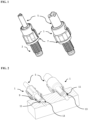
- FIG. 1 shows hoses 5 which are connected to a fitting 1 that has a thread 2.
- a ring 7 is arranged at the fitting as a marker enabling to distinguish different fittings/hoses transferring different liquids.
- FIG. 2 shows hoses 5 which are interlocked in two-part torsional fittings 1.
- the screw connection 9 is resistant against vibrational movements and pressure.
- the front side 11 is pressed against the thread ground 13 so that a reliable sealing results even during pressurization.
- FIG. 3 shows sectional views of two different embodiments with hoses 5 having a different diameter, which are glued into the inner part 15 of a two-part torsional fitting 1 according to the invention.
- the inner part 15 of a two-part torsional fitting 1 can be transparent so that the gluing can be optically verified.
- Outer part 25 surrounds inner part 15.
- the inner part 15 has a first section 16 between the opening for a hose 18 on a first end 22 of the inner part 15 and its base ground 20.
- the first section 16 further comprises a transition area 24 to the second section 17.
- the transition area 24 may also be part of the seconde section 17 or may be arranged between first and seconf section 16, 17.
- the first section 16 of inner part 15 is surrounded by a grip element 26 of outer part 25.
- Transition area 24 may be shaped conically (left part of FIG. 3 ) or in one step (right part FIG. 3 ).
- the inner part 15 has further a second section 17 starting below transistion area 24 of the first part 15 and a second end 23 of the inner part 15. Second section 17 of inner part 15 is surrounded by a thread 27 on outer part 25.
- the inner part 15 has a flange at the second end 23.
- outer part 25 is fixed between first section 16 of the inner part 15, which has a larger diameter than its second section 17 and flange 21.
- FIG. 3 show further that there is no significant reduction of the inner diamter in the transition from the hose to inner part 15 of the two-part torsinal fitting 1. Thus, the flow of liquids will not be influenced or impeded.
- One advantage of the invention is to provide a user-friendly connection and disconnection of hose connections made of thermoplastic elastomers.
- the direct bonding of the hose within the fitting eliminates the need to attach the hose.
- the entire composite can be screwed and tightened by hand through the thread. In case of a necessary replacement, the entire composite can be unscrewed. Peeling off the tube, which may cause injuries is eliminated.
- Another advantage is the lack of mechanical stress by the torsional fitting. It is not possible to twist or torisnal stress the hose during screwing due to the possibility of rotational decoupling. The hose can not exert any mechanical stress on the periphery regardless of the bending radii after screwing.
- the two-part torsianl fitting has no significant cross-sectional changes which may cause turbulences.
- the constant cross-section of the complete composite does not allow the formation of turbulences at cross-sectional changes, edges, heels, etc. This reduces interfering effects such as spontaneous outgassing or cavitation.
- Another advantage of the present invention in this regard is that no significant cross-sectional reductions are present that may act as flow resistances. Any flow resistors are omitted.
- a safe cohesive connection between hose and connector is a further advante provided by the present invention.
- the material connection between the fitting and hose generates a connection which is not susceptible to mechanical effects, e.g. tensile forces, vibrations, pressure or the like. This makes the entire composite safe and reliable during application.
- the present invention further provides a pressure resistant connection by pressing two sealing surfaces via screw connection on a counterpart.
- This type of pressure-resistant connection is also used in hydraulics, where only two sealing surfaces are pressed against each other. The necessary contact pressure is applied via a thread. A high gear reduction results from screwing because of the pitch of the thread. Thus, the sealing connection can be made only by hand.
- the selected slope prevents self-locking an independent release of the connection.
- the possibility to visually inspect the adhesive bond by using transparent materials is an advantage, so that the cohesively produced compound can be verified immediately after bonding. Inclusions of air bubbles, use of too much or too little adhesive and damage to the fitting or hose will be immediately visible.
- the flange 21 may also be fixed to a one part fitting 1a as a separate component ( FIG. 4 ).
- One possibility to fix such a flange 21 can be to glue it to hose 5.
- the above described methods for reshaping the end of the hose or applying an additional part to a hose's end to generate a sealing effect between fitting screw, hose and counterpart relate mostly refer to fluoropolymers.
- materials which can not just be plugged because of their low surface energy, their creep behavior, their high hardness or their pressure resistance.
- Pressure-resistant hoses may also be made of materials with a higher surface energy, so that materials can be added by cohesive methods such as gluing them.
- Thermoplastic polyurethanes belong to the thermoplastic elastomers, which can be treated with a suitable solvent.
- a flange 21 made of an appropritae material may be treated in the same way e.g.the inner surface may be dissolved with a solvent, so that both part can be connectedor cold welded.
- the other possibility is to glue the hose 5 into the inner part 15 of the two-part torsional fitting 1, similar to the method described above.
- Flange 21 shown in FIG. 4 forms an undercut.
- the inner and outer parts (15, 25) can be mounted together only by a deformation of the outer part. This is realized over a defined elastic range of both components so that they are locked together.
- the flange 21 can be made separately.
- a further approach is that the inner part and hose can be connected directly in the injection molding tool instead of glueing them.
- the hose is inserted in the tool and overmoulded with the plastic.
Landscapes
- Engineering & Computer Science (AREA)
- General Engineering & Computer Science (AREA)
- Mechanical Engineering (AREA)
- Health & Medical Sciences (AREA)
- Clinical Laboratory Science (AREA)
- Chemical & Material Sciences (AREA)
- Chemical Kinetics & Catalysis (AREA)
- Rigid Pipes And Flexible Pipes (AREA)
- Joints That Cut Off Fluids, And Hose Joints (AREA)
Description
- The invention relates to a hose connection for tubes of automated analyser systems transferring mediums like liquid fluids.
- Automated analyser systems for use in clinical diagnostics and life sciences are produced by a number of companies. For example, STRATEC® SE, Birkenfeld, Germany, produces a number of devices for specimen handling and detection for use in automated analyser systems and other laboratory instrumentation.
- The most common manner for connecting hoses that transfer liquids are screw couplings. The parts which are connect are usually made of fluoropolymers such as PTFE or FEP, in particular in the field of analysis and medical technology. Such materials provide media resistance and pressure resistance. Due to their strong creep behavior and their relatively high hardness, these hoses cannot simply be put together for connection. Special fitting screws are used for such couplings.
- A tube's or hose's end is reshaped, or a flange is formed at its end using heat and pressure in order to obtain a sealed connection between the fitting and its counterpart. Such a molded flange seals between the front of the fitting and the threat root of the counterpart. A ring may be arranged between flange and fitting for uncoupling torsion forces that may occur during tightening of fitting and its counterpart.
- A disadvantage of this method is that the process of flange forming requires a number of auxiliary devices or tools. On the one hand, a holding device for the hose is needed and on the other hand the actual forming tool. Often, a heated mandrel is used, which heats the tube before forming. In addition, just with this type of screw often chipped items made of materials such as PEEK are used. Especially the assembly and the parts production make this type of connection costly. In addition, the forming of such a hose connection requires some experience in the assembly and is therefore not too user friendly. The method applies only to the hard fluoropolymer tubing. Thermoplastic elastomers cannot be reshaped to the required precision due to their elasticity and lower Shore hardness.
- An alternative to reshaping the end of a tube or hose is an insert that is a gasket with a cylindric hose connection and a ring for rotational decoupling. For mounting, the fitting screw is pushed over the tube or hose followed by the ring and finally, the insert is introduced into the tube or hose.
- Comparable to the connection with the formed hose, often pure machined small parts made of high-quality plastics can be used in this process. The sealing flange consists of a disc with a dome. This dome is inserted with slight excess in the hose. Due to the high hardness of the hose and the small size of the components, this results in an increased effort in the assembly. By inserting the dome in the hose whose cross-section is reduced which results in a flow resistance in the system. Depending on the flow rate, the fluid is compressed in front of the dome and undergoes an expansion behind the cross-sectional reduction, which can lead to undesired turbulence.
- Another possibility for sealing is to use an elastomer seal that is put over the tube's end, so that sealing takes place at the outside of the tube. In this variant, the tightness to the hose and the actual sealing seat in the counterpart is made only by an elastomeric element. Just the tightness to the counterpart is thus always dependent on the installation. If the sealing part is pushed too far onto the hose, there is no connection between the elastomer and the counterpart. The tightness is therefore no longer present. The assembly is difficult on the one hand due to the specified tolerance problem and on the other hand because of the required assembly forces. It is recommended to use a mounting device. This increases the effort and thus the costs. As with the aforementioned methods, this connection technique is limited to the rather hard fluoropolymer hoses. Sliding the connector onto softer hoses would reduce its cross section. In addition, it is questionable whether the seal part can ever postpone due to the higher friction values.
- A very simple method for connecting tubes with a Shore hardness below 85 A is the use of a so-called barb connector, where the tube is put over a mandrel with a greater outer diameter than the inner diameter of the tube. In order to provide a secure connection, the mandrel shall be mushroom-shaped. This is the most common, tool-free way of connecting hoses. It is widely used when it comes to fluid transport in the low-pressure range. The hose is only put over the counterpart. The resulting, in places multiple line contact between fitting and hose guarantees the seal between the two partners. However, just this slipping also has some disadvantages. On the one hand, depending on the hardness of the hose and the selected excess between fitting and hose, the assembly is difficult. With increasing excess or increasing hardness, the contact forces, which are usually applied manually, increase sharply. To counteract, the excess can be reduced with increasing the hose hardness or wall thickness. As the excess decreases, however, the compressive strength of the overall connection also decreases. For pressure applications and the use of highly pulsating pumps, this connection may have an undefined instability. The fitting will be screwed into a counterpart. If the hose is connected to the fitting prior to screwing the fitting into its counterpart, the connection may loosen due to tensions in the hoses resulting from twisting them.
- For a quick connection and release a so-called Luer lock is very often used in medical devices. Such a connection is based on two coupling pieces which are connected and sealed only by a self-locking cone. In the Lock variant results from an external thread, which can be closed by a 90 ° - rotation, an additional closure of a pulling apart of the conical connection and thus prevents leaks. A disadvantage of a Luer lock is that the partners of the lock are twisted against each other with the result that the hose is twisted in its elastic range. Under certain circumstances, this can mean that the connection loosens itself due to the elasticity of the hose and that leaks can occur.
- In order to prevent just that twisting of the hose, this can be biased by a 90 ° rotation against the closing direction of the thread. This has the advantage that the hose is tension-free when the clutch is closed. However, this biasing requires an attentive user, the error rate is accordingly high. To counteract this problem, there is a rotation-coupled variant. In this case, the locking thread is loosely connected as an additional union nut with the actual Luer cone. If the clutch is now closed, the counterpart can only be recognized, by tightening the torsional coupled cap nut of the actual cone, which is connected to the hose is pressed without rotation into the cone of the counterpart.
- The locking thread of the Luer Lock coupling is designed for an ergonomically comfortable ¼ turn. In order to realize a way in these only 90 ° rotation angle sufficient to connect the coupling partner of lots to hard a fairly large pitch is required. This large thread pitch reduces the self-locking of the thread to a significantly low level. This has the consequence that this locking thread reliably locked only with a firmly connected Luer cone and this lock also holds. In the described rotationally coupled variant, the friction of the Luer cones is eliminated. The torsional coupled union nut can only jam due to the adhesion between the screw and nut threads (self-locking). However, since this is reduced by the large pitch there is always the risk of an independent release of the locking thread. In this case, the holding force consists only of the two inserted Luer cone. Thus, with dynamically loaded systems, oscillating or vibrating connections as well as connections which are subject to strong temperature changes, this type of coupling can very quickly lead to errors.
- Published U.S. Patent Application No.
US 2018/0128405 A1 relates to a single action push to connect fitting for a conduit such as tube or pipe. The fitting includes a first fitting component and a second fitting component that are joined or assembled together to form a fitting assembly. The fitting assembly includes a conduit seal device and a conduit retaining device. A conduit may be manually or otherwise inserted into the assembled fitting assembly with a single axial movement and be retained and sealed without the need for further action or movement of the fitting components. A disadvantage of a fitting assembly according to this publication is that it comprises multiple parts making its assembly complex. - Published U.S. Patent Application No.
US 2019/0128460 A1 relates to a tube end form, including, a first section including a first radially outward facing surface, and a shoulder axially arranged between the first and second sections, the shoulder including a first frusto-conical surface arranged at a first angle relative to the first radially outward facing surface, and a second frusto-conical surface arranged at a second angle relative to the first radially outward facing surface. This document does not relate to a connector suitable for accommodating a hose for its fixation in the connector. - It is therefore the object of this invention to provide a stable and pressure resistant hose connection.
- The present invention provides a connector for a hose transferring a medium, as disclosed in
claim 1. - In a further aspect of the invention, the inner diameter of the opening for the hose may conically reduce towards the inner base of the opening for the hose
- It is further intended that the inner part is made of a transparent material.
- In a further embodiment of a connector according to the invention, the outer part's grip may provide at its end adjacent or next to the thread a surface for accommodating a marker. The surface for accommodating a marker may surround the outer part.
- With respect to the inner diameter of the opening for the hose it may be identical or smaller than the outer diameter of the hose that is accommodated in the opening.
- In a further aspect of the invention, the connector's outer part may have a 6.35 mm (¼ - 28UNF) thread.
- In a further embodiment of the present invention, the inner part may be inserted into the outer part.
- Another object of the invention is a first system comprising a connector as described above and a hose. It is further intended with respect to the first system that a hose may be accommodated in the opening of the inner part, e.g. the inner diameter of the opening for accommodating the hose is identical or smaller than the outer diameter of the hose that is accommodated in the opening or with an adhesive between outer diameter of the hose and inner diameter of the opening for the hose.
- It is intended that hoses with an outer diameter of up to 7 mm can be accommodated into the inner part's opening for the hose.
- Another object of the present invention is a second system comprising a first system as described above and a counterpart for the connector's part thread having a female thread corresponding to the thread of the connector's outer part.
- Another object of the present invention is the use of a connector as described above or a first or second system as described above for connecting a hose. The connection may be to another hose or to a solid counterpart having a female thread.
- Still other aspects, features, and advantages of the present invention are readily apparent from the following detailed description, simply by illustrating preferable embodiments and implementations. Accordingly, the drawings and descriptions are to be regarded as illustrative in nature, and not as restrictive. Additional objects and advantages of the invention will be set forth in part in the description which follows and in part will be obvious from the description, or may be learned by practice of the invention.
- The invention will be described based on figures. It will be understood that the embodiments and aspects of the invention described in the figures are only examples and do not limit the protective scope of the claims in any way. The invention is defined by the claims.
-
FIG. 1 shows hoses which are connected to a fitting according to the invention. -
FIG. 2 shows which are interlocked in two-part torsional fittings. -
FIG. 3 shows sectional views through two-part torsional fittings according to the invention. -
FIG.4 shows a one-part fitting with an attached flange -
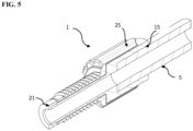
FIG. 5 shows a two-part torsional fitting with an attached flange. - The technical problem is solved by the independent claims. The dependent claims cover further specific embodiments of the invention.
- The term inner base ground refers to an inner surface of the inner part against which the end of a hose is pressed. The inner base ground is thus the difference in diameter between the diameter of the opening for accommodating a hose in a first section of the inner part and the diameter of the duct in a second section of the inner part.
- The outer part is fixed around the inner part in a manner that the outer part can be rotated around the inner part. Thus, the outer part is fixed rotationally movable around a longitudinal axis around the inner part. The outer part may be fixed between a flange located at the inner part's second end (end of second section) and a diameter transition area to the larger diameter of the first section.
- The term 'medium' shall refer within the meaning of the present invention to a liquid, a liquid comprising solid parts like particles of any material and of biological or synthetic origin. The medium may also be gaseous comprising liquid droplets and/or solid particles.
- A marker within the meaning of the present invention refers to elements that may be used to label a connector so that it can be differentiated from other connectors. A marker can be a ring or an adhesive comprising a specific color or any barcode. A RFID tag may also be a marker according to the present invention.
- The present example refers to a two-part, torsional coupled fitting within the meaning of a fitting screw for female thread (e.g. 6.35 mm (¼ - 28UNF) ) in which thermoplastic elastomer hoses with an outer diameter of up to 7 mm can be glued without the need of additional components such as a flange that has to be attached to the hose's end to achieve tightness.
- The inner part of the torsional coupled fitting generates the sealing connection between the hose and the counterpart. The hose is merely joined with a solvent adhesive cohesively into the inner part. The sealing connection results from pressing the end face of the inner part against the thread root of the counterpart.
- The outer part establishes the mechanical connection between the inner part and the counterpart. Here, the inner part is anchored in the outer part. This is done by plugging together and then anchoring both components. The outer part may have a thread (e.g. ¼-28UNF) and provides the necessary mechanical contact force or pressure to the inner part and is thus responsible for the contact force or pressure of the inner part to the end face of the thread root of the counterpart. This combination of bonding techniques enables the transfer of pressures comparable to those of classic joints (e.g. 6.35 mm (¼ - 28UNF)).
- Inner part and outer part are merely inserted into each other and thus determined along a z-axis only translational, a rotational movement about the z-axis is remaining. This results in the end in the necessary rotational decoupling between hose and screwed outer part. The hose that is cohesively connected to the inner part can be connected to the nut thread without twisting it.
- The thread (e.g. 6.35 mm (¼ - 28UNF)) has a comparatively low pitch regarding the locking thread of a Luer lock connection. Usually, fittings with threads (e.g. 6.35 mm (¼ - 28UNF)) require between 5 and 9 turns to establish a reliable connection between two coupling partners. The resulting self-locking between screw and nut thread is significantly higher compared to the locking thread of the Luer lock connection. As a result, these connections remain permanently sealed even with vibrations and temperature changes.
- Very thin walls can be realized in both components by using specific plastics. If the fitting is completely mounted and screwed in addition, the circumferential nut thread additionally supports the connection. This makes it possible to realize internal cross sections of up to 3.2 mm in the fitting. This means that hoses can be connected to the inner diameter of 3.2 mm within the respective fitting, without the need of significantly reducing the inner diameter and thus affecting the flow rate.
- Using transparent plastics allows to inspect visually and assess the joining process between hose and inner part. Defective connections can thus be identified quite easy even before fitting the fitting parts.
- The present invention allows to connect thermoplastic elastomer hoses in a very small space with other systems. The connection does not significantly reduce the cross-section of the hose line. In addition, the connection is pre-stressed via the thread (e.g. 6.35 mm (¼ - 28UNF)) and is therefore pressure-resistant and protected against loosening by itself.
- A connection according to the present invention shall fulfill the following requirements
- Pressure-resistant up to min. 8bar
- Low cost structure
- Simple installation
- Resistant to vibration
- Suitable for thermoplastic elastomers such as PVC or TPU as tubing
- No or no significant reduction in cross-section flow
- Connection through a thread, e,g, 6.35 mm (¼ - 28UNF)
- Optical assignment of several hoses
- Tolerant of incorrectly executed hose cuts (angularity, surface quality).
- The embodiment shown in
FIG. 1 showshoses 5 which are connected to a fitting 1 that has athread 2. Aring 7 is arranged at the fitting as a marker enabling to distinguish different fittings/hoses transferring different liquids. - The exemplary design shown in
FIG. 2 showshoses 5 which are interlocked in two-part torsional fittings 1. Thescrew connection 9 is resistant against vibrational movements and pressure. Thefront side 11 is pressed against thethread ground 13 so that a reliable sealing results even during pressurization. -
FIG. 3 shows sectional views of two different embodiments withhoses 5 having a different diameter, which are glued into theinner part 15 of a two-part torsional fitting 1 according to the invention. Theinner part 15 of a two-part torsional fitting 1 can be transparent so that the gluing can be optically verified. -
Outer part 25 surroundsinner part 15. Theinner part 15 has afirst section 16 between the opening for ahose 18 on afirst end 22 of theinner part 15 and itsbase ground 20. Thefirst section 16 further comprises atransition area 24 to thesecond section 17. Thetransition area 24 may also be part of theseconde section 17 or may be arranged between first andseconf section first section 16 ofinner part 15 is surrounded by agrip element 26 ofouter part 25.Transition area 24 may be shaped conically (left part ofFIG. 3 ) or in one step (right partFIG. 3 ). - The
inner part 15 has further asecond section 17 starting belowtransistion area 24 of thefirst part 15 and asecond end 23 of theinner part 15.Second section 17 ofinner part 15 is surrounded by athread 27 onouter part 25. - In both embodiments shown in
FIG. 3 , theinner part 15 has a flange at thesecond end 23. Thus,outer part 25 is fixed betweenfirst section 16 of theinner part 15, which has a larger diameter than itssecond section 17 andflange 21. - The sectional views in
FIG. 3 show further that there is no significant reduction of the inner diamter in the transition from the hose toinner part 15 of the two-part torsinal fitting 1. Thus, the flow of liquids will not be influenced or impeded. - One advantage of the invention is to provide a user-friendly connection and disconnection of hose connections made of thermoplastic elastomers. The direct bonding of the hose within the fitting eliminates the need to attach the hose. The entire composite can be screwed and tightened by hand through the thread. In case of a necessary replacement, the entire composite can be unscrewed. Peeling off the tube, which may cause injuries is eliminated.
- Another advantage is the lack of mechanical stress by the torsional fitting. It is not possible to twist or torisnal stress the hose during screwing due to the possibility of rotational decoupling. The hose can not exert any mechanical stress on the periphery regardless of the bending radii after screwing.
- The two-part torsianl fitting has no significant cross-sectional changes which may cause turbulences. The constant cross-section of the complete composite does not allow the formation of turbulences at cross-sectional changes, edges, heels, etc. This reduces interfering effects such as spontaneous outgassing or cavitation.
- Another advantage of the present invention in this regard is that no significant cross-sectional reductions are present that may act as flow resistances. Any flow resistors are omitted.
- A safe cohesive connection between hose and connector is a further advante provided by the present invention. The material connection between the fitting and hose generates a connection which is not susceptible to mechanical effects, e.g. tensile forces, vibrations, pressure or the like. This makes the entire composite safe and reliable during application.
- The present invention further provides a pressure resistant connection by pressing two sealing surfaces via screw connection on a counterpart. This type of pressure-resistant connection is also used in hydraulics, where only two sealing surfaces are pressed against each other. The necessary contact pressure is applied via a thread. A high gear reduction results from screwing because of the pitch of the thread. Thus, the sealing connection can be made only by hand. In addition, the selected slope prevents self-locking an independent release of the connection.
- Finally, the possibility to visually inspect the adhesive bond by using transparent materials is an advantage, so that the cohesively produced compound can be verified immediately after bonding. Inclusions of air bubbles, use of too much or too little adhesive and damage to the fitting or hose will be immediately visible.
- Alternative approaches to circumvent or realize the present example encompass the use of currently used fluoropolymer hoses, which have the above mentioned advantages of rotational, decoupling, constant flow cross-section, pressure stability etc.
- The
flange 21 may also be fixed to a one part fitting 1a as a separate component (FIG. 4 ). One possibility to fix such aflange 21 can be to glue it tohose 5. The above described methods for reshaping the end of the hose or applying an additional part to a hose's end to generate a sealing effect between fitting screw, hose and counterpart relate mostly refer to fluoropolymers. Thus, materials which can not just be plugged because of their low surface energy, their creep behavior, their high hardness or their pressure resistance. Pressure-resistant hoses may also be made of materials with a higher surface energy, so that materials can be added by cohesive methods such as gluing them. Thermoplastic polyurethanes (TPU) belong to the thermoplastic elastomers, which can be treated with a suitable solvent. Aflange 21 made of an appropritae material may be treated in the same way e.g.the inner surface may be dissolved with a solvent, so that both part can be connectedor cold welded. - Thus, it will be possible with such an approach to apply cohesively a
flange 21 made of TPU on the front side of thehose 5 made of TPU. In this case, the reshaping of the hose's end or inserting an additional part into it will be eliminated. However, it it will also be required that anadditional decoupling ring 30 is added for decoupling torsional forces between the fitting 1a andflange 21 when tightening the composite. - The other possibility is to glue the
hose 5 into theinner part 15 of the two-part torsional fitting 1, similar to the method described above.Flange 21 shown inFIG. 4 forms an undercut. Thus, the inner and outer parts (15, 25) can be mounted together only by a deformation of the outer part. This is realized over a defined elastic range of both components so that they are locked together. Alternatively, theflange 21 can be made separately. Thus, it will be possible to first insert the outer and inner parts (15, 25) into each other. Subsequently,flange 21 is glued to the front side of the inner part and thus fixes the inner and outer parts to each other (FIG. 5 ). - A further approach is that the inner part and hose can be connected directly in the injection molding tool instead of glueing them. The hose is inserted in the tool and overmoulded with the plastic.
- The foregoing description has been presented for purposes of illustration and description. It is not intended to be exhaustive or to limit the invention to the precise form disclosed. It is intended that the scope of the invention be defined by the claims appended hereto.
-
- 1
- two-part torsional fitting
- 1a
- one part fitting
- 2
- thread
- 5
- hose
- 7
- ring
- 9
- screw connection
- 11
- front side
- 13
- thread ground
- 15
- inner part
- 16
- first section
- 17
- second section
- 18
- opening for hose
- 19
- duct
- 20
- base ground
- 21
- flange
- 22
- first end
- 23
- second end
- 24
- diameter transition area
- 25
- outer part
- 26
- grip element
- 27
- thread
- 30
- decoupling ring
Claims (14)
- A connector for a hose transferring a medium, comprising- an inner part (15), wherein the inner part (15) comprises at a first (22) end a first section (16) comprising an opening (18) for accommodating a hose (5) and a second section (17) comprising a duct (19) which is arranged between an inner base ground (20) of the opening (18) for accommodating the hose (5) and a second end (23) of the inner part (15) that is opposite of the first end (22), wherein the first section (16) has a greater outer diameter than the second section (17); and- an outer part (25), wherein the outer part (25) comprises a thread (2) surrounding the second section (17) and a grip (26) surrounding the first section (16),wherein the outer part (25) is fixed between a flange (21) located at the inner part's second end (23) and a diameter transition area (24) to the larger diameter of the first section (16) of the inner part (15) only rotationally movable around the inner part (15).
- The connector of claim 1, wherein the inner diameter of the opening (18) for the hose (5) is conically reduced towards the inner base ground (20) of the opening (18) for the hose (5).
- The connector of any one of claim 1 or 2, wherein the inner part (15) is made of a transparent material.
- The connector of any one of claims 1 to 3, wherein the outer part's grip (26) provides at its end adjacent to the thread (2) a surface for accommodating a marker.
- The connector of claim 4, wherein the surface for accommodating a marker surrounds the outer part (25).
- The connector of any one of claims 1 to 5, wherein the outer part (25) has a 6.35 mm thread.
- The connector of any one of claims 1 to 6, wherein the inner part (15) is inserted into the outer part (25).
- A first system, comprising a connector according to any one of claims 1 to 7 and a hose (5).
- The first system of claim 8, wherein the inner diameter of the duct (19) is identical to the outer diameter of the hose (5).
- The first system of any one of claims 8 or 9, wherein the inner diameter of the opening (18) for accommodating the hose (5) is identical or smaller than the outer diameter of the hose (5) that is accommodated in the opening (18).
- The first system of any one of claims 8 to 10, wherein a hose (5) is accommodated in the opening (18) of the inner part (15) with an adhesive between outer diameter of the hose (5) and inner diameter of the opening (18) for the hose (5).
- The first system of any one of claims 8 to 11, wherein a hose (5) with an outer diameter of up to 7 mm is accommodated in the inner part's opening (18) for the hose (5).
- A second system comprising a first system according to any one of claims 8 to 12 and a counterpart for the connector's outer part (25) thread (2) having a female thread corresponding to the thread (2) of the connector's outer part (25).
- The use of a connector according to any one of claims 1 to 7, a first system according to any one of claims 8 to 12 and a second system of claim 13 for connecting a hose (5).
Applications Claiming Priority (1)
| Application Number | Priority Date | Filing Date | Title |
|---|---|---|---|
| LU101498A LU101498B1 (en) | 2019-11-26 | 2019-11-26 | Hose connector |
Publications (2)
| Publication Number | Publication Date |
|---|---|
| EP3828456A1 EP3828456A1 (en) | 2021-06-02 |
| EP3828456B1 true EP3828456B1 (en) | 2024-09-11 |
Family
ID=69158283
Family Applications (1)
| Application Number | Title | Priority Date | Filing Date |
|---|---|---|---|
| EP20209816.6A Active EP3828456B1 (en) | 2019-11-26 | 2020-11-25 | Hose connector |
Country Status (3)
| Country | Link |
|---|---|
| US (1) | US12331866B2 (en) |
| EP (1) | EP3828456B1 (en) |
| LU (1) | LU101498B1 (en) |
Families Citing this family (3)
| Publication number | Priority date | Publication date | Assignee | Title |
|---|---|---|---|---|
| CN114607856B (en) * | 2022-03-08 | 2023-11-17 | 徐州市华为工程机械有限公司 | Quick-change joint for pipeline |
| GB2641111A (en) * | 2024-05-17 | 2025-11-19 | Stratec Se | Hose connector |
| FR3165565A1 (en) * | 2024-08-13 | 2026-02-20 | Alain Martin | Device for cleaning the suction system of agricultural sprayers |
Citations (1)
| Publication number | Priority date | Publication date | Assignee | Title |
|---|---|---|---|---|
| EP0845093B1 (en) * | 1995-08-18 | 2001-02-28 | Aeroquip Corporation | Coupling assembly |
Family Cites Families (8)
| Publication number | Priority date | Publication date | Assignee | Title |
|---|---|---|---|---|
| US1771949A (en) * | 1928-08-30 | 1930-07-29 | Charles Cory & Son Inc | Hose fitting |
| US3112127A (en) * | 1960-06-06 | 1963-11-26 | L & L Mfg Company | Fluid pressure tube fitting |
| US3502355A (en) * | 1969-04-03 | 1970-03-24 | Amp Inc | Pipe,hose or tube fluid connection device |
| US3627262A (en) * | 1970-01-22 | 1971-12-14 | Dwight E Hottle | Valve having axially shifting closure means |
| US9597475B2 (en) * | 2011-07-15 | 2017-03-21 | Jack C McPhearson | Fast connect device for oxygen humidity bottles and other medical containers |
| JP6199668B2 (en) * | 2013-09-12 | 2017-09-20 | 日機装株式会社 | Connector |
| EP3060839B1 (en) * | 2013-10-24 | 2020-03-18 | Swagelok Company | Single action push to connect conduit fitting |
| US10781958B2 (en) * | 2017-10-31 | 2020-09-22 | Oetiker Ny, Inc. | Low peak insertion tube end form |
-
2019
- 2019-11-26 LU LU101498A patent/LU101498B1/en active IP Right Grant
-
2020
- 2020-11-24 US US17/102,794 patent/US12331866B2/en active Active
- 2020-11-25 EP EP20209816.6A patent/EP3828456B1/en active Active
Patent Citations (1)
| Publication number | Priority date | Publication date | Assignee | Title |
|---|---|---|---|---|
| EP0845093B1 (en) * | 1995-08-18 | 2001-02-28 | Aeroquip Corporation | Coupling assembly |
Also Published As
| Publication number | Publication date |
|---|---|
| US20210156501A1 (en) | 2021-05-27 |
| EP3828456A1 (en) | 2021-06-02 |
| US12331866B2 (en) | 2025-06-17 |
| LU101498B1 (en) | 2021-05-28 |
Similar Documents
| Publication | Publication Date | Title |
|---|---|---|
| US12331866B2 (en) | Hose connector | |
| CN101896756B (en) | threaded connection | |
| CN102788203B (en) | Fittings and fluid lines for fluid lines | |
| US20140265312A1 (en) | Apparatuses and methods for providing finger-tightened and ratchet-secured connections between conduits | |
| US20130119659A1 (en) | Single axis push to connect conduit fitting | |
| CN100334383C (en) | Fitting assembly and method | |
| CN101821541A (en) | Connect by moment of torsion lasso pipe joint | |
| JPH04266685A (en) | Connection system of pressure-proof pipe joint | |
| JP3661903B2 (en) | Threaded joint for inner surface coated pipe | |
| CA2686084A1 (en) | Fitting with bushing for corrugated stainless steel tubing | |
| KR20060113387A (en) | Resin Pipe Connection Unit | |
| US20110127771A1 (en) | Fittings for high pressure hydraulic couplings | |
| US12111003B2 (en) | Bonded slip joint pipe fitting | |
| CN1019682B (en) | Tube Clamp Connections | |
| AU2025202878A1 (en) | A device for making plumbing connections and a method of use thereof | |
| TWI225134B (en) | Connector | |
| US12345362B2 (en) | Hose coupling and method for use in analysis systems | |
| KR102035976B1 (en) | Pipe fitting having anti-loosening structure | |
| GB2641111A (en) | Hose connector | |
| JP2004347014A (en) | Pipe fittings | |
| US20190137015A1 (en) | Zero dead volume fitting assembly | |
| US20050067794A1 (en) | Thermoplastic seal and method | |
| EP1502052B1 (en) | Pipe connection for pipe pieces made of plastic | |
| US20090167017A1 (en) | Plug connector for piping | |
| US20060157983A1 (en) | High pressure coupling device and method |
Legal Events
| Date | Code | Title | Description |
|---|---|---|---|
| PUAI | Public reference made under article 153(3) epc to a published international application that has entered the european phase |
Free format text: ORIGINAL CODE: 0009012 |
|
| STAA | Information on the status of an ep patent application or granted ep patent |
Free format text: STATUS: THE APPLICATION HAS BEEN PUBLISHED |
|
| AK | Designated contracting states |
Kind code of ref document: A1 Designated state(s): AL AT BE BG CH CY CZ DE DK EE ES FI FR GB GR HR HU IE IS IT LI LT LU LV MC MK MT NL NO PL PT RO RS SE SI SK SM TR |
|
| STAA | Information on the status of an ep patent application or granted ep patent |
Free format text: STATUS: REQUEST FOR EXAMINATION WAS MADE |
|
| 17P | Request for examination filed |
Effective date: 20211202 |
|
| RBV | Designated contracting states (corrected) |
Designated state(s): AL AT BE BG CH CY CZ DE DK EE ES FI FR GB GR HR HU IE IS IT LI LT LU LV MC MK MT NL NO PL PT RO RS SE SI SK SM TR |
|
| P01 | Opt-out of the competence of the unified patent court (upc) registered |
Effective date: 20230710 |
|
| STAA | Information on the status of an ep patent application or granted ep patent |
Free format text: STATUS: EXAMINATION IS IN PROGRESS |
|
| 17Q | First examination report despatched |
Effective date: 20231023 |
|
| REG | Reference to a national code |
Ref legal event code: R079 Free format text: PREVIOUS MAIN CLASS: F16L0019000000 Ipc: B01L0003000000 Ref country code: DE Ref legal event code: R079 Ref document number: 602020037456 Country of ref document: DE Free format text: PREVIOUS MAIN CLASS: F16L0019000000 Ipc: B01L0003000000 |
|
| GRAP | Despatch of communication of intention to grant a patent |
Free format text: ORIGINAL CODE: EPIDOSNIGR1 |
|
| STAA | Information on the status of an ep patent application or granted ep patent |
Free format text: STATUS: GRANT OF PATENT IS INTENDED |
|
| GRAS | Grant fee paid |
Free format text: ORIGINAL CODE: EPIDOSNIGR3 |
|
| GRAA | (expected) grant |
Free format text: ORIGINAL CODE: 0009210 |
|
| STAA | Information on the status of an ep patent application or granted ep patent |
Free format text: STATUS: THE PATENT HAS BEEN GRANTED |
|
| RIC1 | Information provided on ipc code assigned before grant |
Ipc: A61M 39/00 20060101ALI20240709BHEP Ipc: F16L 33/00 20060101ALI20240709BHEP Ipc: F16L 37/00 20060101ALI20240709BHEP Ipc: F16L 19/00 20060101ALI20240709BHEP Ipc: A61M 39/10 20060101ALI20240709BHEP Ipc: B01L 3/00 20060101AFI20240709BHEP |
|
| INTG | Intention to grant announced |
Effective date: 20240725 |
|
| AK | Designated contracting states |
Kind code of ref document: B1 Designated state(s): AL AT BE BG CH CY CZ DE DK EE ES FI FR GB GR HR HU IE IS IT LI LT LU LV MC MK MT NL NO PL PT RO RS SE SI SK SM TR |
|
| REG | Reference to a national code |
Ref country code: GB Ref legal event code: FG4D |
|
| REG | Reference to a national code |
Ref country code: CH Ref legal event code: EP |
|
| REG | Reference to a national code |
Ref country code: DE Ref legal event code: R096 Ref document number: 602020037456 Country of ref document: DE |
|
| REG | Reference to a national code |
Ref country code: IE Ref legal event code: FG4D |
|
| REG | Reference to a national code |
Ref country code: LT Ref legal event code: MG9D |
|
| PG25 | Lapsed in a contracting state [announced via postgrant information from national office to epo] |
Ref country code: NO Free format text: LAPSE BECAUSE OF FAILURE TO SUBMIT A TRANSLATION OF THE DESCRIPTION OR TO PAY THE FEE WITHIN THE PRESCRIBED TIME-LIMIT Effective date: 20241211 |
|
| REG | Reference to a national code |
Ref country code: NL Ref legal event code: MP Effective date: 20240911 |
|
| PG25 | Lapsed in a contracting state [announced via postgrant information from national office to epo] |
Ref country code: GR Free format text: LAPSE BECAUSE OF FAILURE TO SUBMIT A TRANSLATION OF THE DESCRIPTION OR TO PAY THE FEE WITHIN THE PRESCRIBED TIME-LIMIT Effective date: 20241212 Ref country code: FI Free format text: LAPSE BECAUSE OF FAILURE TO SUBMIT A TRANSLATION OF THE DESCRIPTION OR TO PAY THE FEE WITHIN THE PRESCRIBED TIME-LIMIT Effective date: 20240911 |
|
| PG25 | Lapsed in a contracting state [announced via postgrant information from national office to epo] |
Ref country code: BG Free format text: LAPSE BECAUSE OF FAILURE TO SUBMIT A TRANSLATION OF THE DESCRIPTION OR TO PAY THE FEE WITHIN THE PRESCRIBED TIME-LIMIT Effective date: 20240911 |
|
| PG25 | Lapsed in a contracting state [announced via postgrant information from national office to epo] |
Ref country code: LV Free format text: LAPSE BECAUSE OF FAILURE TO SUBMIT A TRANSLATION OF THE DESCRIPTION OR TO PAY THE FEE WITHIN THE PRESCRIBED TIME-LIMIT Effective date: 20240911 |
|
| PG25 | Lapsed in a contracting state [announced via postgrant information from national office to epo] |
Ref country code: HR Free format text: LAPSE BECAUSE OF FAILURE TO SUBMIT A TRANSLATION OF THE DESCRIPTION OR TO PAY THE FEE WITHIN THE PRESCRIBED TIME-LIMIT Effective date: 20240911 |
|
| PG25 | Lapsed in a contracting state [announced via postgrant information from national office to epo] |
Ref country code: ES Free format text: LAPSE BECAUSE OF FAILURE TO SUBMIT A TRANSLATION OF THE DESCRIPTION OR TO PAY THE FEE WITHIN THE PRESCRIBED TIME-LIMIT Effective date: 20240911 |
|
| PG25 | Lapsed in a contracting state [announced via postgrant information from national office to epo] |
Ref country code: NO Free format text: LAPSE BECAUSE OF FAILURE TO SUBMIT A TRANSLATION OF THE DESCRIPTION OR TO PAY THE FEE WITHIN THE PRESCRIBED TIME-LIMIT Effective date: 20241211 Ref country code: LV Free format text: LAPSE BECAUSE OF FAILURE TO SUBMIT A TRANSLATION OF THE DESCRIPTION OR TO PAY THE FEE WITHIN THE PRESCRIBED TIME-LIMIT Effective date: 20240911 Ref country code: HR Free format text: LAPSE BECAUSE OF FAILURE TO SUBMIT A TRANSLATION OF THE DESCRIPTION OR TO PAY THE FEE WITHIN THE PRESCRIBED TIME-LIMIT Effective date: 20240911 Ref country code: GR Free format text: LAPSE BECAUSE OF FAILURE TO SUBMIT A TRANSLATION OF THE DESCRIPTION OR TO PAY THE FEE WITHIN THE PRESCRIBED TIME-LIMIT Effective date: 20241212 Ref country code: FI Free format text: LAPSE BECAUSE OF FAILURE TO SUBMIT A TRANSLATION OF THE DESCRIPTION OR TO PAY THE FEE WITHIN THE PRESCRIBED TIME-LIMIT Effective date: 20240911 Ref country code: ES Free format text: LAPSE BECAUSE OF FAILURE TO SUBMIT A TRANSLATION OF THE DESCRIPTION OR TO PAY THE FEE WITHIN THE PRESCRIBED TIME-LIMIT Effective date: 20240911 Ref country code: BG Free format text: LAPSE BECAUSE OF FAILURE TO SUBMIT A TRANSLATION OF THE DESCRIPTION OR TO PAY THE FEE WITHIN THE PRESCRIBED TIME-LIMIT Effective date: 20240911 |
|
| REG | Reference to a national code |
Ref country code: AT Ref legal event code: MK05 Ref document number: 1722222 Country of ref document: AT Kind code of ref document: T Effective date: 20240911 |
|
| PG25 | Lapsed in a contracting state [announced via postgrant information from national office to epo] |
Ref country code: NL Free format text: LAPSE BECAUSE OF FAILURE TO SUBMIT A TRANSLATION OF THE DESCRIPTION OR TO PAY THE FEE WITHIN THE PRESCRIBED TIME-LIMIT Effective date: 20240911 |
|
| PG25 | Lapsed in a contracting state [announced via postgrant information from national office to epo] |
Ref country code: PT Free format text: LAPSE BECAUSE OF FAILURE TO SUBMIT A TRANSLATION OF THE DESCRIPTION OR TO PAY THE FEE WITHIN THE PRESCRIBED TIME-LIMIT Effective date: 20250113 Ref country code: IS Free format text: LAPSE BECAUSE OF FAILURE TO SUBMIT A TRANSLATION OF THE DESCRIPTION OR TO PAY THE FEE WITHIN THE PRESCRIBED TIME-LIMIT Effective date: 20250111 |
|
| PG25 | Lapsed in a contracting state [announced via postgrant information from national office to epo] |
Ref country code: SM Free format text: LAPSE BECAUSE OF FAILURE TO SUBMIT A TRANSLATION OF THE DESCRIPTION OR TO PAY THE FEE WITHIN THE PRESCRIBED TIME-LIMIT Effective date: 20240911 Ref country code: RO Free format text: LAPSE BECAUSE OF FAILURE TO SUBMIT A TRANSLATION OF THE DESCRIPTION OR TO PAY THE FEE WITHIN THE PRESCRIBED TIME-LIMIT Effective date: 20240911 |
|
| PG25 | Lapsed in a contracting state [announced via postgrant information from national office to epo] |
Ref country code: EE Free format text: LAPSE BECAUSE OF FAILURE TO SUBMIT A TRANSLATION OF THE DESCRIPTION OR TO PAY THE FEE WITHIN THE PRESCRIBED TIME-LIMIT Effective date: 20240911 Ref country code: AT Free format text: LAPSE BECAUSE OF FAILURE TO SUBMIT A TRANSLATION OF THE DESCRIPTION OR TO PAY THE FEE WITHIN THE PRESCRIBED TIME-LIMIT Effective date: 20240911 |
|
| PG25 | Lapsed in a contracting state [announced via postgrant information from national office to epo] |
Ref country code: PL Free format text: LAPSE BECAUSE OF FAILURE TO SUBMIT A TRANSLATION OF THE DESCRIPTION OR TO PAY THE FEE WITHIN THE PRESCRIBED TIME-LIMIT Effective date: 20240911 Ref country code: CZ Free format text: LAPSE BECAUSE OF FAILURE TO SUBMIT A TRANSLATION OF THE DESCRIPTION OR TO PAY THE FEE WITHIN THE PRESCRIBED TIME-LIMIT Effective date: 20240911 |
|
| PG25 | Lapsed in a contracting state [announced via postgrant information from national office to epo] |
Ref country code: SK Free format text: LAPSE BECAUSE OF FAILURE TO SUBMIT A TRANSLATION OF THE DESCRIPTION OR TO PAY THE FEE WITHIN THE PRESCRIBED TIME-LIMIT Effective date: 20240911 |
|
| PG25 | Lapsed in a contracting state [announced via postgrant information from national office to epo] |
Ref country code: RS Free format text: LAPSE BECAUSE OF FAILURE TO SUBMIT A TRANSLATION OF THE DESCRIPTION OR TO PAY THE FEE WITHIN THE PRESCRIBED TIME-LIMIT Effective date: 20240911 |
|
| REG | Reference to a national code |
Ref country code: DE Ref legal event code: R097 Ref document number: 602020037456 Country of ref document: DE |
|
| PG25 | Lapsed in a contracting state [announced via postgrant information from national office to epo] |
Ref country code: MC Free format text: LAPSE BECAUSE OF FAILURE TO SUBMIT A TRANSLATION OF THE DESCRIPTION OR TO PAY THE FEE WITHIN THE PRESCRIBED TIME-LIMIT Effective date: 20240911 |
|
| PG25 | Lapsed in a contracting state [announced via postgrant information from national office to epo] |
Ref country code: DK Free format text: LAPSE BECAUSE OF FAILURE TO SUBMIT A TRANSLATION OF THE DESCRIPTION OR TO PAY THE FEE WITHIN THE PRESCRIBED TIME-LIMIT Effective date: 20240911 |
|
| PG25 | Lapsed in a contracting state [announced via postgrant information from national office to epo] |
Ref country code: LU Free format text: LAPSE BECAUSE OF NON-PAYMENT OF DUE FEES Effective date: 20241125 |
|
| PLBE | No opposition filed within time limit |
Free format text: ORIGINAL CODE: 0009261 |
|
| STAA | Information on the status of an ep patent application or granted ep patent |
Free format text: STATUS: NO OPPOSITION FILED WITHIN TIME LIMIT |
|
| 26N | No opposition filed |
Effective date: 20250612 |
|
| REG | Reference to a national code |
Ref country code: BE Ref legal event code: MM Effective date: 20241130 |
|
| PG25 | Lapsed in a contracting state [announced via postgrant information from national office to epo] |
Ref country code: SE Free format text: LAPSE BECAUSE OF FAILURE TO SUBMIT A TRANSLATION OF THE DESCRIPTION OR TO PAY THE FEE WITHIN THE PRESCRIBED TIME-LIMIT Effective date: 20240911 |
|
| PG25 | Lapsed in a contracting state [announced via postgrant information from national office to epo] |
Ref country code: BE Free format text: LAPSE BECAUSE OF NON-PAYMENT OF DUE FEES Effective date: 20241130 |
|
| PG25 | Lapsed in a contracting state [announced via postgrant information from national office to epo] |
Ref country code: IE Free format text: LAPSE BECAUSE OF NON-PAYMENT OF DUE FEES Effective date: 20241125 |
|
| REG | Reference to a national code |
Ref country code: CH Ref legal event code: U11 Free format text: ST27 STATUS EVENT CODE: U-0-0-U10-U11 (AS PROVIDED BY THE NATIONAL OFFICE) Effective date: 20251201 |
|
| PGFP | Annual fee paid to national office [announced via postgrant information from national office to epo] |
Ref country code: DE Payment date: 20251118 Year of fee payment: 6 |
|
| PGFP | Annual fee paid to national office [announced via postgrant information from national office to epo] |
Ref country code: GB Payment date: 20251120 Year of fee payment: 6 |
|
| PGFP | Annual fee paid to national office [announced via postgrant information from national office to epo] |
Ref country code: IT Payment date: 20251128 Year of fee payment: 6 |
|
| PGFP | Annual fee paid to national office [announced via postgrant information from national office to epo] |
Ref country code: FR Payment date: 20251120 Year of fee payment: 6 |
|
| PGFP | Annual fee paid to national office [announced via postgrant information from national office to epo] |
Ref country code: CH Payment date: 20251201 Year of fee payment: 6 |
|
| PG25 | Lapsed in a contracting state [announced via postgrant information from national office to epo] |
Ref country code: HU Free format text: LAPSE BECAUSE OF FAILURE TO SUBMIT A TRANSLATION OF THE DESCRIPTION OR TO PAY THE FEE WITHIN THE PRESCRIBED TIME-LIMIT; INVALID AB INITIO Effective date: 20201125 |
|
| PG25 | Lapsed in a contracting state [announced via postgrant information from national office to epo] |
Ref country code: CY Free format text: LAPSE BECAUSE OF FAILURE TO SUBMIT A TRANSLATION OF THE DESCRIPTION OR TO PAY THE FEE WITHIN THE PRESCRIBED TIME-LIMIT; INVALID AB INITIO Effective date: 20201125 |