EP3828452A1 - Method for assembling motorized valve, and motorized valve - Google Patents
Method for assembling motorized valve, and motorized valve Download PDFInfo
- Publication number
- EP3828452A1 EP3828452A1 EP19840786.8A EP19840786A EP3828452A1 EP 3828452 A1 EP3828452 A1 EP 3828452A1 EP 19840786 A EP19840786 A EP 19840786A EP 3828452 A1 EP3828452 A1 EP 3828452A1
- Authority
- EP
- European Patent Office
- Prior art keywords
- valve
- valve stem
- stopper
- fixed
- stem holder
- Prior art date
- Legal status (The legal status is an assumption and is not a legal conclusion. Google has not performed a legal analysis and makes no representation as to the accuracy of the status listed.)
- Granted
Links
Images








Classifications
-
- F—MECHANICAL ENGINEERING; LIGHTING; HEATING; WEAPONS; BLASTING
- F16—ENGINEERING ELEMENTS AND UNITS; GENERAL MEASURES FOR PRODUCING AND MAINTAINING EFFECTIVE FUNCTIONING OF MACHINES OR INSTALLATIONS; THERMAL INSULATION IN GENERAL
- F16K—VALVES; TAPS; COCKS; ACTUATING-FLOATS; DEVICES FOR VENTING OR AERATING
- F16K31/00—Actuating devices; Operating means; Releasing devices
- F16K31/02—Actuating devices; Operating means; Releasing devices electric; magnetic
- F16K31/04—Actuating devices; Operating means; Releasing devices electric; magnetic using a motor
-
- F—MECHANICAL ENGINEERING; LIGHTING; HEATING; WEAPONS; BLASTING
- F16—ENGINEERING ELEMENTS AND UNITS; GENERAL MEASURES FOR PRODUCING AND MAINTAINING EFFECTIVE FUNCTIONING OF MACHINES OR INSTALLATIONS; THERMAL INSULATION IN GENERAL
- F16K—VALVES; TAPS; COCKS; ACTUATING-FLOATS; DEVICES FOR VENTING OR AERATING
- F16K27/00—Construction of housing; Use of materials therefor
- F16K27/02—Construction of housing; Use of materials therefor of lift valves
- F16K27/029—Electromagnetically actuated valves
-
- F—MECHANICAL ENGINEERING; LIGHTING; HEATING; WEAPONS; BLASTING
- F16—ENGINEERING ELEMENTS AND UNITS; GENERAL MEASURES FOR PRODUCING AND MAINTAINING EFFECTIVE FUNCTIONING OF MACHINES OR INSTALLATIONS; THERMAL INSULATION IN GENERAL
- F16K—VALVES; TAPS; COCKS; ACTUATING-FLOATS; DEVICES FOR VENTING OR AERATING
- F16K31/00—Actuating devices; Operating means; Releasing devices
- F16K31/44—Mechanical actuating means
- F16K31/50—Mechanical actuating means with screw-spindle or internally threaded actuating means
- F16K31/504—Mechanical actuating means with screw-spindle or internally threaded actuating means the actuating means being rotable, rising, and having internal threads which co-operate with threads on the outside of the valve body
-
- F—MECHANICAL ENGINEERING; LIGHTING; HEATING; WEAPONS; BLASTING
- F16—ENGINEERING ELEMENTS AND UNITS; GENERAL MEASURES FOR PRODUCING AND MAINTAINING EFFECTIVE FUNCTIONING OF MACHINES OR INSTALLATIONS; THERMAL INSULATION IN GENERAL
- F16K—VALVES; TAPS; COCKS; ACTUATING-FLOATS; DEVICES FOR VENTING OR AERATING
- F16K2200/00—Details of valves
- F16K2200/40—Bleeding means in closed position of the valve, e.g. bleeding passages
-
- F—MECHANICAL ENGINEERING; LIGHTING; HEATING; WEAPONS; BLASTING
- F25—REFRIGERATION OR COOLING; COMBINED HEATING AND REFRIGERATION SYSTEMS; HEAT PUMP SYSTEMS; MANUFACTURE OR STORAGE OF ICE; LIQUEFACTION SOLIDIFICATION OF GASES
- F25B—REFRIGERATION MACHINES, PLANTS OR SYSTEMS; COMBINED HEATING AND REFRIGERATION SYSTEMS; HEAT PUMP SYSTEMS
- F25B41/00—Fluid-circulation arrangements
- F25B41/30—Expansion means; Dispositions thereof
- F25B41/31—Expansion valves
- F25B41/34—Expansion valves with the valve member being actuated by electric means, e.g. by piezoelectric actuators
- F25B41/35—Expansion valves with the valve member being actuated by electric means, e.g. by piezoelectric actuators by rotary motors, e.g. by stepping motors
-
- Y—GENERAL TAGGING OF NEW TECHNOLOGICAL DEVELOPMENTS; GENERAL TAGGING OF CROSS-SECTIONAL TECHNOLOGIES SPANNING OVER SEVERAL SECTIONS OF THE IPC; TECHNICAL SUBJECTS COVERED BY FORMER USPC CROSS-REFERENCE ART COLLECTIONS [XRACs] AND DIGESTS
- Y02—TECHNOLOGIES OR APPLICATIONS FOR MITIGATION OR ADAPTATION AGAINST CLIMATE CHANGE
- Y02B—CLIMATE CHANGE MITIGATION TECHNOLOGIES RELATED TO BUILDINGS, e.g. HOUSING, HOUSE APPLIANCES OR RELATED END-USER APPLICATIONS
- Y02B30/00—Energy efficient heating, ventilation or air conditioning [HVAC]
- Y02B30/70—Efficient control or regulation technologies, e.g. for control of refrigerant flow, motor or heating
Definitions
- the present invention relates to a method for assembling a motor-operated valve that is used by being incorporated as a flow rate control valve or the like into the refrigeration cycle of an air conditioner, a refrigerator, or the like.
- a motor-operated valve that includes a valve stem having a valve element at its lower end; a guide bush in which the valve stem is adapted to be inserted in a relatively movable and relatively rotatable manner in the axis direction; a valve body having the guide bush press-fit fixed thereto and having a valve seat, the valve element being adapted to move into contact with or away from the valve seat; a valve stem holder that is tubular in shape and has a ceiling portion, the valve stem holder being arranged on the outer periphery side of the guide bush and externally arranged around the valve stem in a relatively movable and relatively rotatable manner in the axis direction; a coil spring provided in a compressed state between the valve stem and the valve stem holder so as to urge the valve element in the direction to close the valve; a fixture fixed to the upper portion of the valve stem and arranged opposite and in contact with the valve stem holder so as to substantially securely couple the
- Motor-operated valves with such a configuration are broadly divided into a closed type and a non-closed type.
- a valve that is widely used as a motor-operated valve of a closed type is adapted to, even after a valve element has been seated on a valve seat, continuously lower (i.e., continuously press) the valve element and press the valve element against the valve seat with a predetermined pressure until a movable stopper collides with a fixed stopper, that is, until a coil spring provided in a compressed state between a valve stem and a valve stem holder is compressed by a predetermined amount (hereinafter referred to as a pressure-closed type).
- a movable stopper is caused to collide with a fixed stopper in a state in which a valve element is open to a small degree before being seated on a valve seat so as to avoid a fully-closed position. That is, when the valve element is at the lowest position, a gap of a predetermined size is formed between the valve element and the valve seat so that a refrigerant is flowed through the gap between the slightly open valve element and the valve seat.
- the position of the base point corresponds to the position where the valve stem holder is at the lowest position
- the compressed amount of the coil spring i.e., a compression coil spring
- the position of the base point is inaccurate, the flow rate control accuracy would decrease, which can result in undesired valve leakage, operation failures, and the like.
- a rotor used for each of the motor-operated valves of a pressure-closed type and a non-closed type is magnetized with bonded magnets, for example, to have alternately different magnetic poles arranged in the circumferential direction (i.e., to have a predetermined number of magnetic poles (for example, 24 magnetic poles) including S-poles and N-poles alternately arranged in the entire circumference of the rotor).
- a stator has upper and lower stator coils in two phases (i.e., A-phase and B-phase), for example, and each stator coil includes a pair of upper and lower yokes, a bobbin attached to the yoke, a coil wound on the bobbin, and the like.
- each yoke is provided with a predetermined number of (for example, 24) magnetic pole teeth each having an elongated nail shape or an isosceles triangle shape and being alternately arranged in opposite directions at predetermined angular intervals.
- a predetermined number of (for example, 24) magnetic pole teeth each having an elongated nail shape or an isosceles triangle shape and being alternately arranged in opposite directions at predetermined angular intervals.
- alignment of the magnetic poles is desirably performed in advance so that an excitation magnetic pole (for example, an N-pole) of the stator coil is arranged directly opposite (i.e., facing the front of) a predetermined magnetic pole (for example, an S-pole) of the rotor when the movable stopper collides with the fixed stopper so as to suppress positional deviation of the rotor in the rotation direction (i.e., the circumferential direction) upon collision between the two stoppers (during initialization, for example) and suppress generation of vibration and noise.
- an excitation magnetic pole for example, an N-pole
- a predetermined magnetic pole for example, an S-pole
- Patent Literature 2 discloses a method for assembling a motor-operated valve that includes, in addition to setting (or managing) the threading start position of the internal threaded portion of the bottom stopper base body and the threading start position of the movable threaded portion (i.e., the internal threaded portion) of the valve stem holder to specific positions, providing a mark (i.e., a D-cut surface or a cutout) for setting (or managing) the press-fit direction (or the orientation) of the guide bush, and setting (or managing) the threading start position of the fixed threaded portion (i.e., the external threaded portion) of the guide bush to a specific position as seen in a top view using the mark, thereby providing a constant correlation between the position of the guide bush in the rotation direction and the positions of the magnetic pole teeth of the stator, so that alignment of the magnetic poles is appropriately performed such that when the movable stopper collides with the fixed stopper, an excitation magnetic pole (for example,
- the present invention has been made in view of the foregoing problems, and it is an object of the present invention to provide a method for assembling a motor-operated valve that allows an excitation magnetic pole of a stator coil and a predetermined magnetic pole of a rotor to be arranged exactly directly opposite each other when the movable stopper collides with the fixed stopper and thus stops, and can accurately perform both the alignment of the magnetic poles and the base point determination without requiring strict dimension management of the guide bush, and the like, and thus can increase the flow rate control accuracy and the like while reducing the parts machining cost, assembly cost, and the like, and can also suppress positional deviation of the rotor in the circumferential direction during initialization and generation of vibration and noise, and also provide the motor-operated valve.
- a method for assembling a motor-operated valve is basically a method for assembling a motor-operated valve, the motor-operated valve including a valve stem with a valve element, a guide bush in which the valve stem is adapted to be inserted in a relatively movable and relatively rotatable manner in an axis direction, a valve body having the guide bush securely attached thereto and having a valve seat, the valve element being adapted to move into contact with or away from the valve seat, a valve stem holder externally arranged around the valve stem in a relatively movable and relatively rotatable manner in the axis direction, an urging member provided between the valve stem and the valve stem holder so as to urge the valve element in a direction to close the valve, a fixture externally fitted to and fixed to the valve stem and arranged opposite and in contact with the valve stem holder so as to substantially securely couple the valve stem and the valve stem holder together in cooperation with the urging member, a can hermetically
- the step (f) includes relatively rotating and lowering the valve stem holder, which has been screwed onto the guide bush by the screw amount, in the direction to close the valve by a rotation angle corresponding to the gap of the predetermined size that should be formed between the valve element and the valve seat, and determining the lowered position of the valve stem holder as a position where the valve stem holder should be finally located with respect to the valve stem.
- the step (f) includes rotating and elevating the valve stem holder, which has been screwed onto the guide bush by the screw amount, in the direction to open the valve by a rotation angle corresponding to an amount of difference that is obtained by subtracting a design value of a length that the urging member should have when the movable stopper collides with the fixed stopper from a design value of a length that the urging member should have when the valve element is seated on the valve seat, and determining the elevated position of the valve stem holder as a position where the valve stem holder should be finally located with respect to the valve stem.
- a center line of a conduit joint to serve as a lateral inlet/outlet of the valve body, or an extended line of the center line is used as the particular straight line passing through the axis of rotation of the bottom stopper base body.
- positioning of the stator with respect to the can and the valve body in the circumferential direction and the vertical direction is performed using a whirl-stop tool attached to one side of a lower face side of the stator, the whirl-stop tool having a pair of arcuate holding portions adapted to hold the conduit joint to serve as the lateral inlet/outlet of the valve body.
- a stopper presser externally attached to the bottom stopper base body in a relatively unrotatable manner and fixed to the immobile portion on the side of the valve body is used for the step of fixing the bottom stopper base body to the immobile portion on the side of the valve body.
- a motor-operated valve basically includes a valve stem with a valve element; a guide bush in which the valve stem is adapted to be inserted in a relatively movable and relatively rotatable manner in an axis direction; a valve body having the guide bush securely attached thereto and having a valve seat, the valve element being adapted to move into contact with or away from the valve seat; a valve stem holder externally arranged around the valve stem in a relatively movable and relatively rotatable manner in the axis direction; an urging member provided between the valve stem and the valve stem holder so as to urge the valve element in a direction to close the valve; a fixture externally fitted to and fixed to the valve stem and arranged opposite and in contact with the valve stem holder so as to substantially securely couple the valve stem and the valve stem holder together in cooperation with the urging member; a can hermetically joined to the valve body; a stepping motor having a rotor and a stator to rotate the valve stem holder with respect to the
- the motor-operated valve further includes a stopper presser externally attached to the bottom stopper base body in a relatively unrotatable manner and fixed to an immobile portion on a side of the valve body.
- the motor-operated valve further includes a conducting member partially embedded in a resin mold on one side of a lower face side of the stator, the conducting member being adapted to electrically connect a yoke of the stator and the valve body; and a whirl-stop tool securely attached to the stator via the conducting member, the whirl-stop tool having a pair of arcuate holding portions adapted to hold a conduit joint to serve as a lateral inlet/outlet of the valve body.
- the motor-operated valve further includes a plurality of pedestal portions radially arranged at equal angular intervals on the lower face side of the stator, any one of the pedestal portions being adapted to have the whirl-stop tool securely attached thereto.
- a predetermined magnetic pole (or the center thereof) of the rotor and the collision-contact plane of the movable stopper with respect to the fixed stopper are allowed to be located on a straight line passing through the axis of rotation of the rotor.
- the position of the collision-contact plane of the fixed stopper with respect to the movable stopper is adjusted to be located on a particular straight line passing through the axis of rotation as seen in a top view, for example, on the center line of a conduit joint to serve as a lateral inlet/outlet of the valve body or on a straight line that is at a predetermined angular interval from the center line.
- positioning of the stator with respect to the can and the valve body is performed using a whirl-stop tool that is attached to one side of the lower face of the stator, for example, and has a pair of arcuate holding portions adapted to hold the conduit joint to serve as the lateral inlet/outlet of the valve body so that an excitation magnetic pole (or the center thereof) of the stator is adjusted to be located on a particular straight line passing through the axis of rotation as seen in a top view, for example, on the center line of the conduit joint to serve as the lateral inlet/outlet of the valve body or on a straight line that is at a predetermined angular interval from the center line.
- a predetermined magnetic pole (or the center thereof) of the rotor, the collision-contact plane of the movable stopper with respect to the fixed stopper, the collision-contact plane of the fixed stopper with respect to the movable stopper, and an excitation magnetic pole (or the center thereof) of the stator are located on a particular straight line passing through the axis of rotation or on a straight line that is at a predetermined angular interval from the particular straight line.
- the excitation magnetic pole (for example, an N-pole) of the stator and the predetermined magnetic pole (for example, an S-pole) of the rotor are allowed to be arranged exactly directly opposite (i.e., facing) each other, and thus, the alignment of the magnetic poles can be appropriately performed.
- the position of the fixture with respect to the valve stem is adjusted so that the position of the valve stem holder with respect to the valve stem in the vertical direction upon collision of the movable stopper with the fixed stopper becomes a predetermined position.
- the motor-operated valve When the motor-operated valve is of a non-closed type, upon collision of the movable stopper with the fixed stopper, a gap of a predetermined size can be formed between the valve element and the valve seat, and also, the number of drive pulses that should be supplied to the stator during initialization or the like becomes accurate (i.e., a minimum required number).
- the length (i.e., the actual length) of the urging member becomes a predetermined length and the valve element can thus be pressed against the valve seat with a predetermined pressure, and also, after the valve element has been seated on the valve seat during initialization, for example, the number of drive pulses that should be supplied to the stator up to the base point position where the movable stopper collides with the fixed stopper and thus stops as well as the number of drive pulses that should be supplied to the stator up to the valve opening point where the valve element is moved away from the valve seat from the base point position, for example, becomes accurate (i.e., a minimum required number).
- the present invention strict management of the bottom stopper base body, the guide bush, the valve stem holder, and the like is not required, and when the movable stopper collides with the fixed stopper, an excitation magnetic pole of the stator coil and a predetermined magnetic pole of the rotor can be arranged exactly directly opposite each other, and thus, both the alignment of the magnetic poles and the base point determination can be accurately performed. Therefore, it is possible to increase the flow rate control accuracy and the like while reducing the parts machining cost, product assembly cost, and the like, and also suppress positional deviation of the rotor in the circumferential direction and the like during initialization. Consequently, generation of vibration and noise can be effectively suppressed.
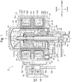
- Fig. 1 is a longitudinal sectional view of an embodiment of a motor-operated valve according to the present invention.
- a motor-operated valve 1 of an embodiment illustrated in Fig. 1 is a non-closed type adapted to be used by being incorporated as a flow rate control valve or the like into the refrigeration cycle of an air conditioner, a refrigerator, or the like, and mainly includes a valve stem 10 having a valve element 14 at its lower end; a guide bush 20; a valve stem holder 30; a valve body 40; a can 55; a stepping motor 50 including a rotor 51 and a stator 52; a coil spring (i.e., an urging member) 60; a fixture 70; a thread feeding mechanism 28; and a stopper mechanism 29.
- the valve stem 10 includes an upper small-diameter portion 11, an intermediate large-diameter portion 12, and a lower small-diameter portion 13 arranged in this order from the upper side.
- the lower end of the lower small-diameter portion 13 is integrally formed with a stepped valve element 14 with an inverted cone shape for controlling the flow rate of a fluid (i.e., refrigerant) to flow through a valve port 46a.
- a fluid i.e., refrigerant
- the guide bush 20 includes a cylindrical portion 21 into which the valve stem 10 (or the intermediate large-diameter portion 12 thereof) is adapted to be inserted in a manner relatively movable (or slidable) in the direction along the axis O and in a manner relatively rotatable about the axis O, and an extension portion 22 that extends upward from the upper end of the cylindrical portion 21, has an inside diameter larger than that of the cylindrical portion 21, and into which the upper end side of the intermediate large-diameter portion 12 and the lower end side of the upper small-diameter portion 11 of the valve stem 10 are adapted to be inserted.
- a fixed threaded portion (i.e., an external threaded portion) 23 which forms one side of the thread feeding mechanism 28 that is adapted to elevate or lower the valve element 14 of the valve stem 10 with respect to a valve seat 46 of the valve body 40 according to the rotational drive of the rotor 51, is formed on the outer periphery of the cylindrical portion 21 of the guide bush 20.
- the lower portion (i.e., a portion below the fixed threaded portion 23) of the cylindrical portion 21 has a large diameter and serves as a fitted portion 27 adapted to be press-fit fixed into a fitting hole 44 provided in the upper portion of the valve body 40.
- an upper face 27a of the fitted portion 27 serves as a receiving portion for regulating the lowering of the bottom stopper base body 25 (that is, defining the position of the bottom stopper base body 25 in the seated state of the valve element described below).
- a stopper presser 48 is attached (i.e., externally attached) to the bottom stopper base body 25 screwed onto the guide bush 20 (or the fixed threaded portion 23 thereof).
- the bottom stopper base body 25 is unrotatably coupled to the guide bush 20 (or the fixed threaded portion 23 thereof) by the stopper presser 48 (as described in detail later).
- the valve stem holder 30 is made of resin, for example (preferably, resin reinforced with SUS or carbon fibers with high wear resistance, considering its contact with the fixture 70), and includes a cylindrical portion 31 into which the guide bush 20 is adapted to be inserted, and a ceiling portion 32 with an insertion hole 32a through which the upper end of the valve stem 10 (or the upper small-diameter portion 11 thereof) is adapted to be inserted (in a state relatively movable in the direction of the axis O and relatively rotatable about the axis O).
- resin for example (preferably, resin reinforced with SUS or carbon fibers with high wear resistance, considering its contact with the fixture 70)
- a cylindrical portion 31 into which the guide bush 20 is adapted to be inserted and a ceiling portion 32 with an insertion hole 32a through which the upper end of the valve stem 10 (or the upper small-diameter portion 11 thereof) is adapted to be inserted (in a state relatively movable in the direction of the axis O and relatively rotatable about the
- the lower portion of the inner periphery of the cylindrical portion 31 of the valve stem holder 30 has formed therein a movable threaded portion (i.e., an internal threaded portion) 33 that is adapted to be screwed onto the fixed threaded portion 23 of the guide bush 20 and thus forms the thread feeding mechanism 28.
- the upper portion of the inner periphery of the cylindrical portion 31 is adapted to abut (i.e., be in sliding contact with) the outer periphery of the cylindrical extension portion 22 of the guide bush 20.
- a movable stopper 34 that forms the other side of the stopper mechanism 29 is formed in a protruding manner and integrally with the lower end of the outer periphery of the cylindrical portion 31.
- two projections 35 that are approximately fan-shaped (herein, in the shape of a fan with a central angle of about 90 degrees) are integrally formed with the upper face of the ceiling portion 32 of the valve stem holder 30 (i.e., a face opposite the flange portion 72 of the fixture 70 described below) so as to reduce the rotary-sliding resistance between the valve stem holder 30 and the fixture 70.
- a cylindrical coil spring 60 which is adapted to urge the valve stem 10 in the direction away from the valve stem holder 30 in the up-down direction (i.e., the direction of the axis O), that is, to always urge the valve stem 10 (i.e., the valve element 14) downward (i.e., in the direction to close the valve), is provided in a compressed state between a terrace face (i.e., a step portion) 15, which is formed between the upper small-diameter portion 11 and the intermediate large-diameter portion 12 of the valve stem 10, and the lower face of the ceiling portion 32 of the valve stem holder 30 such that the cylindrical coil spring 60 is externally arranged around the upper small-diameter portion 11 of the valve stem 10 with interposed therebetween a disk-shaped pressing plate (i.e., a washer) 61 arranged on the lower face side of the ceiling portion 32 of the valve stem holder 30.
- a disk-shaped pressing plate i.e., a washer
- the coil spring 60 is adapted to substantially securely couple the valve stem 10 and the valve stem holder 30 together in cooperation with the fixture 70 described below, and is able to finely adjust the position of the valve stem holder 30 with respect to the valve stem 10 by utilizing the elasticity of the coil spring 60 during assembly of the motor-operated valve 1.
- the valve body 40 is a cylindrical body made of metal, such as brass or SUS, for example.
- the valve body 40 includes a valve chamber 40a into/from which a fluid is introduced/discharged.
- a first conduit joint 41 which serves as a fluid inlet/outlet, is securely coupled to a first lateral opening 41a provided on the lateral portion of the valve chamber 40a by brazing, for example.
- the ceiling portion of the valve chamber 40a has formed therein an insertion hole 43 through which the valve stem 10 (or the intermediate large-diameter portion 12 thereof) is adapted to be inserted in a state relatively movable (or slidable) in the direction along the axis O and relatively rotatable about the axis O, and a fitting hole 44 into which the lower portion (i.e., the fitted portion 27) of the guide bush 20 is adapted to be press-fit fixed.
- a second conduit joint 42 which serves as a fluid inlet/outlet, is securely coupled to a second longitudinal opening 42a provided at the bottom of the valve chamber 40a by brazing, for example.
- a bottom wall 45 between the valve chamber 40a and the second opening 42a has formed therein a stepped valve port 46a having a valve seat 46 which the valve element 14 is adapted to be moved into contact with or away from.
- the outer periphery of the upper end of the valve body 40 (i.e., the outer side of the valve body 40 opposite to the guide bush 20) has an annular flanged plate 47 fixed thereto by swaging, brazing, or the like.
- the lower end of the cylindrical can 55 with a ceiling is hermetically joined to a step portion provided on the outer periphery of the flanged plate 47 by butt welding, for example.
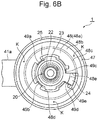
- the upper face (i.e., the surface on the can 55 side) of the flanged plate 47 has securely arranged thereon the stopper presser 48 that is a stepped, approximately plate-like member adapted to engage with the bottom stopper base body 25 and prevent relative rotation of the bottom stopper base body 25 with respect to the guide bush 20.
- the stopper presser 48 is formed by press work or the like using a metal member, such as brass or SUS, for example.
- a metal member such as brass or SUS, for example.
- the stopper presser 48 is basically adapted to engage with the bottom stopper base body 25 in a state separated from (i.e., floating above) the valve body 40 (or the upper face thereof) and the flanged plate 47 (or the upper face thereof) provided on the valve body 40, and the outer periphery portion of the stopper presser 48 (i.e., a portion on the outer side of an annular step portion 48c thereof) is adapted to abut the flanged plate 47 (or the upper face thereof) and is securely joined thereto by welding, adhesion, bonding, or the like.
- the stopper presser 48 includes a disk-shaped attachment support portion 48a that is attached (i.e., externally attached) to the bottom stopper base body 25 and is arranged apart from the valve body 40 (or the upper face thereof), and an annular attachment fixation portion 48b that is provided on the outer periphery of the attachment support portion 48a with the step portion 48c interposed therebetween and is securely attached to the flanged plate 47 provided on the outer periphery of the valve body 40.
- the attachment support portion 48a has formed therein a fit-insertion hole 48d with a size that allows the bottom stopper base body 25 to be inserted therethrough.
- Three support claws 49a, 49b, and 49c which are rectangular in shape as seen in a side view and are adapted to hold the bottom stopper base body 25 (or the outer face thereof), are provided in upright position on the attachment support portion 48a, at positions adjacent to the fit-insertion hole 48d (that is, on the outer periphery portion of the fit-insertion hole 48d).
- the three support claws 49a, 49b, and 49c are provided in upright position so as to be opposite the outer surface of the bottom stopper base body 25, and the support claw 49c, which is relatively small of the three (i.e., has a relatively small width in the circumferential direction and a relatively small height), is arranged adjacent to a fan-shaped portion 48e of the fit-insertion hole 48d in which the fixed stopper 24, which is fan-shaped as seen in a top view, is adapted to be fitted and inserted (specifically, adjacent to the side face of the fixed stopper 24 fitted and inserted in the fan-shaped portion 48e in the direction to open the valve).
- a support claw i.e., a support portion 49d, which is rectangular in shape as seen in the circumferential direction, is provided in upright position on the outer periphery portion of the fan-shaped portion 48e (specifically, a portion adjacent to the side face of the fixed stopper 24 fitted and inserted in the fan-shaped portion 48e in the direction to close the valve on the side opposite to the side face in the direction to open the valve) so as to be opposite the outer surface of the fixed stopper 24 (i.e., the side face in the direction to close the valve).
- the support claw 49d holds the opposite side faces of the fixed stopper 24 in the circumferential direction together with the support claw 49c.
- the lower end (i.e., the proximal portion) of the support claw 49d is provided with a curved portion (also referred to as an R-shaped portion) 49e formed to have a predetermined radius as seen in the radial direction (i.e., the lateral direction).
- the support claw 49d is elastically deformable in the circumferential direction.
- the support claw 49d elastically deforms (i.e., warps) in the circumferential direction upon collision of the movable stopper 34 provided on the valve stem holder 30 with the fixed stopper 24 provided on the bottom stopper base body 25, so that the impact (in the circumferential direction) is relaxed.
- the bottom stopper base body 25 (or the fixed stopper 24 thereof) supported by the support claw 49d is pushed back to its original position or posture with the elastic restoring force of the support claw 49d.
- the attachment fixation portion 48b of the stopper presser 48 is securely joined to the approximately central portion of the flanged plate 47 (or the upper face thereof) by welding, adhesion, bonding, or the like (i.e., a joined portion K). Accordingly, the bottom stopper base body 25 is relatively unrotatably coupled to the guide bush 20 (or the fixed threaded portion 23 thereof).
- the rotor 51 is rotatably provided on the inner side of the can 55 and on the outer side of the guide bush 20 and the valve stem holder 30, while the stator 52 is externally fitted to and held by the outer periphery of the can 55 so as to rotationally drive the rotor 51.
- the stator 52 is formed by molding using thermoplastic resin, and includes stator coils 52A and 52B in two phases (i.e., A-phase and B-phase).
- the upper stator coil 52A includes a pair of upper and lower yokes 52u and 52v, a bobbin 52b attached to the yokes 52u and 52v, a coil 52c wound on the bobbin 52b, and the like.
- the lower stator coil 52B has a configuration obtained by inverting the configuration of the upper stator coil 52A upside down, and includes a pair of upper and lower yokes 52u and 52v, a bobbin 52b attached to the yokes 52u and 52v, a coil 52c wound on the bobbin 52b, and the like. Void portions on the outer periphery of and inside the stator coils 52A and 52B are covered with and filled with molding resin (i.e., a resin mold 52d as a resin portion), and thus are sealed.
- molding resin i
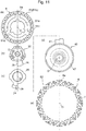
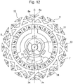
- each of the pair of upper and lower yokes 52u and 52v (or the stator coils 52A and 52B) is provided with, as schematically illustrated in Figs. 11 and 12 , a plurality of (for example, 24) magnetic pole teeth 6 or 7 each having an elongated nail shape or an isosceles triangle shape and being alternately arranged in opposite directions at predetermined angular intervals.
- the rotor 51 rotates once with 96 pulses, for example.
- a lateral portion of the stator coils 52A and 52B covered with the resin mold 52d is provided with a lead wire connection portion (i.e., a connector portion) 52C.
- the connector portion 52C is provided with a substrate 52f and a connector 52i for connecting a plurality of coil terminal pins 52e and a plurality of lead wires 52h, and has attached thereto a cover 52j to cover the upper portions of the coil terminal pins 52e, the substrate 52f, the connector 52i, the lead wires 52h, and the like.
- the inside of the cover 52j is filled with resin 52k, such as silicone resin, and thus is sealed.
- the rotor 51 arranged in the can 55 is externally arranged around and supported by the valve stem holder 30, and the valve stem holder 30 is adapted to rotate together with (or integrally with) the rotor 51.
- the rotor 51 has, as schematically illustrated in the top view of Fig. 3 , a double-cylinder structure of an inner cylinder 51a, an outer cylinder 51b, and connection portions 51c for connecting the inner cylinder 51a and the outer cylinder 51b at predetermined angular positions around the axis O.
- Longitudinal grooves 51d extending in the direction of the axis O (i.e., the vertical direction) are formed on the inner periphery of the inner cylinder 51a (for example, at angular intervals of 120 degrees around the axis O).
- the outer cylinder 51b of the rotor 51 is molded with bonded magnets, for example, and is magnetized to have alternately different magnetic poles in the circumferential direction (i.e., a magnetized portion 8 with a plurality of magnetic poles 8a) so that 24 magnetic poles including S-poles and N-poles are alternately arranged in the entire circumference of the outer cylinder 51b.
- the upper end of the outer periphery (or the upper half thereof) of the valve stem holder 30 is provided with a tapered face portion 30c having a circular truncated cone face.
- Elongated protrusions 30a extending in the vertical direction are provided below the tapered face portion 30c (for example, at angular intervals of 120 degrees around the axis O), and upward engagement faces 30b adapted to support the rotor 51 are formed on the opposite sides of the lower portion of each elongated protrusion 30a.
- the rotor 51 As described above, as the longitudinal grooves 51d of the inner cylinder 51a of the rotor 51 engage with the elongated protrusions 30a of the valve stem holder 30, and as the lower face of the inner cylinder 51a of the rotor 51 abuts the engagement faces 30b of the valve stem holder 30, the rotor 51 is externally arranged around and fixed to the valve stem holder 30 while being positioned with respect to the valve stem holder 30, and the valve stem holder 30 rotates integrally with the rotor 51 while supporting the rotor 51 within the can 55.
- a predetermined magnetic pole 8a (or the center thereof) of the rotor 51 and a collision-contact plane Jb of the movable stopper 34 with respect to the fixed stopper 24 are positioned on a straight line CA passing through the axis O of rotation, as illustrated in a partially cutaway view of Fig. 4 .
- the rotor 51 engages with and is supported by the valve stem holder 30 so that the upper face of the valve stem holder 30 is located to be flush with or slightly above the upper face of the inner cylinder 51a of the rotor 51.
- the upper side of the rotor 51 and the valve stem holder 30 is provided with a fixture 70 that is adapted to be externally fitted to and fixed to the upper end of the valve stem 10 (or the upper small-diameter portion 11 thereof) so as to prevent relative movement of the valve stem holder 30 and the rotor 51 in the up-down direction (that is, to allow the rotor 51 to engage with the valve stem holder 30 while preventing slippage therebetween) and to couple the valve stem 10 and the valve stem holder 30 together.
- the fixture 70 is formed by press work, cutting work, or the like using a metal member, such as brass or SUS, for example, and includes a stepped cylindrical fixation portion 71, which includes an upper small-diameter portion 71a that is adapted to be externally fitted to the upper end of the valve stem 10 (or the upper small-diameter portion 11 thereof) and be securely joined thereto by press fit, welding, adhesion, bonding, or the like and a lower large-diameter portion 71b; and a disk-shaped flange portion 72 extending outward from the lower end of the fixation portion 71 (or the lower large-diameter portion 71b thereof) to a region around the inner cylinder 51a of the rotor 51.
- a metal member such as brass or SUS
- the middle portion of the upper small-diameter portion 71a (in the vertical direction) is welded in the direction from the lateral side (i.e., the outer periphery side) to the valve stem 10 side so that the fixture 70 is joined to a region around the upper end of the valve stem 10 (or the upper small-diameter portion 11 thereof) (i.e., a welded portion W).
- welding may be performed at a plurality of portions in the circumferential direction (around the axis O; for example, three points at equal intervals (i.e., equal angular intervals) in the circumferential direction) (for example, at the same time) or may be performed along the entire circumferential direction.
- the lower face of the flange portion 72 is adapted to be opposite the upper face of the valve stem holder 30 and the upper face of the rotor 51 (or the inner cylinder 51a thereof), and is adapted to be opposite and in contact with the projections 35 (or the upper faces thereof) provided on the upper face of the valve stem holder 30 and the rotor 51 (or the upper face of the inner cylinder 51a thereof).
- the rotor 51 is held between the valve stem holder 30, which is urged upward with the urging force of the coil spring 60, and the fixture 70 (or the outer periphery portion of the flange portion 72 thereof), and engages therewith so that slippage is prevented.
- a restoring spring 75 which is a coil spring adapted to urge the valve stem holder 30 to the guide bush 20 side, is externally attached to the fixture 70 (or the lower large-diameter portion 71b of the fixation portion 71 thereof) fixed to the upper end of the valve stem 10 so as to prevent too much upward movement of the valve stem holder 30 with respect to the guide bush 20 during operation and thus prevent the threaded disengagement between the fixed threaded portion 23 of the guide bush 20 and the movable threaded portion 33 of the valve stem holder 30.
- a bifurcated whirl-stop tool 65 is securely attached to one side of the lower face side of the stator 52 to prevent relative rotation and relative movement of the stator 52 with respect to the can 55 and the valve body 40, that is, to perform positioning.
- the whirl-stop tool 65 is formed by stamping press work or the like using a conductive metal plate, and includes, as illustrated in Figs. 7A and 7B , a rectangular flat plate-like portion 65a and a pair of wavy plate-like elastic holding pieces 65b extending downward from the right and left inner periphery sides of the flat plate-like portion 65a and having arcuate holding portions 65d adapted to (elastically) hold the first conduit joint 41.
- the flat plate-like portion 65a has formed therein a through-hole 65e for passing a protruding portion at the lower end of a conducting member 62 described below, and a through-hole 65f for passing a positioning protrusion 66 formed in the resin mold 52d.
- a conducting member 62 for electrically connecting the yoke 52u at the bottom of the stator 52 and the valve body 40 via the whirl-stop tool 65 is insert-molded in the resin mold 52d on one side of the lower face side of the stator 52 (in this example, the side of the lead wire connection portion 52C).
- the conducting member 62 is adapted to prevent generation of undesired electric discharge between the yokes 52u and 52v and the can 55, is formed in the shape of a cylinder with a flanged portion (i.e., step portion), has a lower end protruding downward (from the resin mold 52d), and is inserted through the through-hole 65e of the whirl-stop tool 65 and is fixed thereto by swaging or the like.
- pedestal portions 63 each adapted to have the whirl-stop tool 65 securely attached thereto are radially arranged at four positions of the resin mold 52d that are at angular intervals of 90° including the portion where the conducting member 62 is arranged, and the positioning protrusion 66 adapted to be inserted through the through-hole 65f of the whirl-stop tool 65 is provided in a protruding manner at each pedestal portion 63.
- stator 52 When the stator 52 is externally arranged around the can 55 and the pair of elastic holding pieces 65b (or the arcuate holding portions 65d thereof) of the bifurcated whirl-stop tool 65 are made to engage with the conduit joint 41 to serve as the lateral inlet/outlet of the valve body 40 so as to hold the conduit joint 41, the stator 52 is fixed while being positioned with respect to the can 55 and the valve body 40 in the circumferential direction and the vertical direction. In the state in which the stator 52 is positioned, as illustrated in Figs.
- the configurations of the guide bush 20 having the fixed threaded portion (i.e., the external threaded portion) 23, the bottom stopper base body 25 having the internal threaded portion 26, and the valve stem holder 30 having the movable threaded portion (i.e., the internal threaded portion) 33 will be supplementarily described from the perspective of base point determination (i.e., initialization).
- the guide bush 20 is not provided with a mark (i.e., a D-cut surface or a cutout) for setting (or managing) the orientation of the guide bush 20 with respect to the fitting hole 44 of the valve body 40 unlike the motor-operated valve described as a conventional example (Patent Literature 2).
- the threading start position i.e., the upper end side
- the fixed threaded portion i.e., the external threaded portion
- the threading start position (i.e., the lower end side) of the internal threaded portion 26 of the bottom stopper base body 25 in the circumferential direction (as seen in a top view) is arranged at the same position as a collision-contact plane Ja of the fixed stopper 24 with respect to the movable stopper 34
- the threading start position (i.e., the lower end side) of the movable threaded portion (i.e., the internal threaded portion) 33 of the valve stem holder 30 in the circumferential direction (as seen in a top view) is arranged at the same position as the collision-contact plane Jb of the movable stopper 34 with respect to the fixed stopper 24. That is, in the bottom stopper base body 25 and the valve stem holder 30, the collision-contact plane Ja of the fixed stopper 24 and the collision-contact plane Jb of the movable stopper 34 are used as marks for the respective threading start positions.
- valve stem holder 30 when the valve stem holder 30 is screwed onto the guide bush 20 and is rotated in the direction to close the valve (for example, clockwise as seen in a top view), the valve stem holder 30 is lowered (moves in a spiral manner) while being rotated by one pitch per rotation, and finally, the movable stopper 34 (or the collision-contact plane Jb thereof) collides with the fixed stopper 24 (or the collision-contact plane Ja thereof) and stops as illustrated in Fig. 8 .
- valve stem holder 30 and the valve stem 10 are rotated integrally with the rotor 51.
- the valve stem 10 is elevated or lowered together with the valve element 14 by the thread feeding mechanism 28, which includes the fixed threaded portion 23 of the guide bush 20 and the movable threaded portion 33 of the valve stem holder 30, so that the gap between the valve element 14 and the valve seat 46 (i.e., the lift amount or the valve opening degree) is increased or decreased and the flow rate of a fluid to flow through the valve port 46a is adjusted.
- the predetermined magnetic pole 8a (or the center thereof) of the rotor 51 and the collision-contact plane Jb of the movable stopper 34 with respect to the fixed stopper 24 are located on the straight line CA passing through the axis O of rotation of the rotor 51 (see Fig. 4 ).
- the position of the collision-contact plane Ja of the fixed stopper 24 with respect to the movable stopper 34 is adjusted so that it is located on a particular straight line passing through the axis O of rotation as seen in a top view, that is, on the center line C of the conduit joint 41 to serve as the lateral inlet/outlet of the valve body 40 herein.
- stator 52 positioning of the stator 52 with respect to the can 55 and the valve body 40 is performed using the bifurcated whirl-stop tool 65 attached to one side of the lower face of the stator 52, for example, so that the predetermined excitation magnetic pole 6a (or the center thereof) of the stator 52 is adjusted to be located on the center line C of the conduit joint 41 passing through the axis O of rotation as seen in a top view.
- the predetermined magnetic pole 8a (or the center thereof) of the rotor 51, the collision-contact plane Jb of the movable stopper 34 with respect to the fixed stopper 24, the collision-contact plane Ja of the fixed stopper 24 with respect to the movable stopper 34, and the excitation magnetic pole 8a (or the center thereof) of the stator 52 are located on the center line C passing through the axis O of rotation.
- the excitation magnetic pole 6a for example, an N-pole
- the predetermined magnetic pole 8a for example, an S-pole
- the alignment of the magnetic poles can be appropriately performed.
- the position of the fixture 70 with respect to the valve stem 10 is adjusted so that the position of the valve stem holder 30 with respect to the valve stem 10 in the vertical direction upon collision of the movable stopper 34 with the fixed stopper 24 is located at a predetermined position.
- base point determination can be accurately performed as well as the aforementioned alignment of the magnetic poles.
- the motor-operated valve 1 When the motor-operated valve 1 is of a non-closed type as in this example, upon collision of the movable stopper 34 with the fixed stopper 24, a gap of a predetermined size can be formed between the valve element 14 and the valve seat 46, and also, the number of drive pulses that should be supplied to the stator 52 during initialization and the like becomes accurate (i.e., a minimum required number).
- the method for assembling the motor-operated valve 1 of this example strict management of the guide bush 20, the valve body 40, and the like is not required, and when the movable stopper 34 collides with the fixed stopper 24, the predetermined excitation magnetic pole 6a of the stator 52 and the predetermined magnetic pole 8a of the rotor 51 can be arranged exactly directly opposite each other, and thus, both the alignment of the magnetic poles and the base point determination can be accurately performed. Therefore, it is possible to increase the flow rate control accuracy and the like while reducing the parts machining cost, product assembly cost, and the like, and also suppress positional deviation of the rotor 51 in the circumferential direction and the like during initialization. Consequently, generation of vibration and noise can be effectively suppressed.
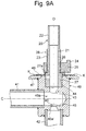
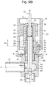
- the motor-operated valve 2 of a pressure-closed type illustrated in Figs. 13 and 14 shares many configurations in common with the aforementioned motor-operated valve 1 of a non-closed type illustrated in Figs. 1 to 12 .
- portions corresponding to the motor-operated valve 1 of a non-closed type are denoted by the same reference numerals or related reference numerals and overlapped description will be omitted.
- the following will mainly describe the difference of the configuration of the motor-operated valve 2 of a pressure-closed type and the assembling method therefor (in particular, the assembling method) from the configuration of the motor-operated valve 1 of a non-closed type and the assembling method therefor.
- the method for assembling the motor-operated valve 2 of a pressure-closed type of this example is approximately the same as the method for assembling the motor-operated valve 1 of a non-closed type up to the following steps:
- the length (i.e., the actual length) of the coil spring (i.e., the urging member) 60 becomes a predetermined length and the valve element 14 can thus be pressed against the valve seat 46 with a predetermined pressure upon collision of the movable stopper 34 with the fixed stopper 24, and also, after the valve element 14 has been seated on the valve seat 46 during initialization, for example, the number of drive pulses that should be supplied to the stator 52 up to the base point position where the movable stopper 34 collides with the fixed stopper 24 and thus stops as well as the number of drive pulses that should be supplied to the stator 52 up to the valve opening point where the valve element 14 is moved away from the valve seat 46 from
- the aforementioned embodiment illustrates an example in which positioning of the stator 52 with respect to the can 55 and the valve body 40 is performed using the bifurcated whirl-stop tool 65 attached to one side of the lower face of the stator 52, and the positioning is performed such that an excitation magnetic pole (or the center thereof) of the stator 52 is located on a particular straight line passing through the axis O of rotation as seen in a top view, specifically, on the center line C of the conduit joint 41 to serve as the lateral inlet/outlet of the valve body 40, the particular straight line passing through the axis O of rotation is not limited to the center line C. That is, since the magnetic poles of the stator 52 are arranged such that the same configuration is repeated every 30° as illustrated in Fig. 12 , it is acceptable as long as a straight line that is at an interval of 30° from the center line C is used as the particular straight line passing through the axis O of rotation.
- the conducting member 62 for electrically connecting the yoke 52u and the valve body 40 is embedded in the resin mold 52d on one side of the lower face side of the stator 52 of this example.
- the conducting member 62 is adapted to prevent generation of undesired electric discharge between the yokes 52u and 52v and the can 55, is formed in the shape of a cylinder with a flanged portion (i.e., step portion), and has a lower end protruding downward (from the resin mold 52d).
- the aforementioned bifurcated whirl-stop tool 65 is securely attached to the stator 52 via the conducting member 62 (i.e., with the lower end of the conducting member 62 inserted through the through-hole 65e of the whirl-stop tool 65 and fixed thereto by swaging, expansion, or the like).
- pedestal portions 63 each adapted to have the whirl-stop tool 65 securely attached thereto are radially arranged at a plurality of positions including the portion where the conducting member 62 is arranged on the lower face side of the stator 52, specifically, four positions that are at angular intervals of 90° in this example.
- the positioning protrusion 66 adapted to be inserted through the through-hole 65f of the whirl-stop tool 65 is provided in a protruding manner at each pedestal portion 63.
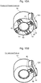
- Each pedestal portion 63 can have the whirl-stop tool 65 securely attached thereto as long as the conducting member 62 is inserted as illustrated in Figs. 16 .
- a pedestal portion is provided only at one position as illustrated in Fig. 15B .
- the pedestal portions 63 are radially provided at a plurality of positions as in this example, it becomes only necessary to change the position of insertion of the conducting member 62 when changing the attachment position of the whirl-stop tool 65. That is, although it has been conventionally necessary to change a mold to change the attachment position of the whirl-stop tool 65, adopting the aforementioned configuration can eliminate the need to change a mold when changing the attachment position of the whirl-stop tool 65, and thus can easily change the attachment position of the whirl-stop tool 65.
- the bifurcated whirl-stop tool 65 attached to one side of the lower face of the stator 52 is caused to engage with the conduit joint 41 to perform positioning of the stator 52 with respect to the can 55 and the valve body 40, and when the movable stopper 34 collides with the fixed stopper 24, the excitation magnetic pole (for example, an N-pole) of the stator 52 and the predetermined magnetic pole 8a (for example, an S-pole) of the rotor 51 can be arranged exactly directly opposite (facing) each other, and thus, the alignment of the magnetic poles can be performed appropriately.
- the excitation magnetic pole for example, an N-pole
- the predetermined magnetic pole 8a for example, an S-pole
- the excitation magnetic pole of the stator 52 and the predetermined magnetic pole of the rotor 51 can be arranged exactly directly opposite (i.e., facing) each other even when the attachment position of the whirl-stop tool 65 is changed by 90°.
Landscapes
- Engineering & Computer Science (AREA)
- General Engineering & Computer Science (AREA)
- Mechanical Engineering (AREA)
- Physics & Mathematics (AREA)
- Electromagnetism (AREA)
- Electrically Driven Valve-Operating Means (AREA)
Abstract
Description
- The present invention relates to a method for assembling a motor-operated valve that is used by being incorporated as a flow rate control valve or the like into the refrigeration cycle of an air conditioner, a refrigerator, or the like.
- As a motor-operated valve of this type, for example, there is conventionally known a motor-operated valve that includes a valve stem having a valve element at its lower end; a guide bush in which the valve stem is adapted to be inserted in a relatively movable and relatively rotatable manner in the axis direction; a valve body having the guide bush press-fit fixed thereto and having a valve seat, the valve element being adapted to move into contact with or away from the valve seat; a valve stem holder that is tubular in shape and has a ceiling portion, the valve stem holder being arranged on the outer periphery side of the guide bush and externally arranged around the valve stem in a relatively movable and relatively rotatable manner in the axis direction; a coil spring provided in a compressed state between the valve stem and the valve stem holder so as to urge the valve element in the direction to close the valve; a fixture fixed to the upper portion of the valve stem and arranged opposite and in contact with the valve stem holder so as to substantially securely couple the valve stem and the valve stem holder together in cooperation with the coil spring; a can hermetically joined to the valve body; a stepping motor including a rotor and a stator to rotate the valve stem holder with respect to the guide bush, the rotor being externally arranged around and fixed to the valve stem holder, the stator being externally fitted to and fixed to the can; a thread feeding mechanism including a fixed threaded portion and a movable threaded portion to elevate or lower the valve element with respect to the valve seat, the fixed threaded portion being formed on the outer periphery of the guide bush, the movable threaded portion being formed on the inner periphery of the valve stem holder; and a stopper mechanism including a fixed stopper and a movable stopper to regulate the rotational lowering of the valve stem holder, the fixed stopper being provided on a bottom stopper base body having an internal threaded portion adapted to be screwed onto the fixed threaded portion of the guide bush, the movable stopper being provided on the valve stem holder (For example, see
Patent Literatures 1 and 2). - Motor-operated valves with such a configuration are broadly divided into a closed type and a non-closed type. A valve that is widely used as a motor-operated valve of a closed type is adapted to, even after a valve element has been seated on a valve seat, continuously lower (i.e., continuously press) the valve element and press the valve element against the valve seat with a predetermined pressure until a movable stopper collides with a fixed stopper, that is, until a coil spring provided in a compressed state between a valve stem and a valve stem holder is compressed by a predetermined amount (hereinafter referred to as a pressure-closed type).
- Meanwhile, in a motor-operated valve of a non-closed type, a movable stopper is caused to collide with a fixed stopper in a state in which a valve element is open to a small degree before being seated on a valve seat so as to avoid a fully-closed position. That is, when the valve element is at the lowest position, a gap of a predetermined size is formed between the valve element and the valve seat so that a refrigerant is flowed through the gap between the slightly open valve element and the valve seat.
- In each of the aforementioned motor-operated valves of a pressure-closed type and a non-closed type, the position where the movable stopper collides with the fixed stopper (i.e., the position of the base point for control = 0 pls position) is important. In the motor-operated valve of a pressure-closed type, the position of the base point corresponds to the position where the valve stem holder is at the lowest position, and the compressed amount of the coil spring (i.e., a compression coil spring) provided in a compressed state between the valve stem and the valve stem holder is determined by the position of the base point. Meanwhile, in the motor-operated valve of a non-closed type, the position of the base point corresponds to the position where the valve element is at the lowest position, and the size of the gap between the valve element and the valve seat (i.e., the lift amount = the valve opening degree) is determined by the position of the base point. In the motor-operated valve of each of such types, if the position of the base point is inaccurate, the flow rate control accuracy would decrease, which can result in undesired valve leakage, operation failures, and the like.
- Meanwhile, a rotor used for each of the motor-operated valves of a pressure-closed type and a non-closed type is magnetized with bonded magnets, for example, to have alternately different magnetic poles arranged in the circumferential direction (i.e., to have a predetermined number of magnetic poles (for example, 24 magnetic poles) including S-poles and N-poles alternately arranged in the entire circumference of the rotor).
- In addition, a stator has upper and lower stator coils in two phases (i.e., A-phase and B-phase), for example, and each stator coil includes a pair of upper and lower yokes, a bobbin attached to the yoke, a coil wound on the bobbin, and the like.
- The inner periphery side of each yoke is provided with a predetermined number of (for example, 24) magnetic pole teeth each having an elongated nail shape or an isosceles triangle shape and being alternately arranged in opposite directions at predetermined angular intervals.
- In the motor-operated valve having a stopper mechanism as described above, alignment of the magnetic poles is desirably performed in advance so that an excitation magnetic pole (for example, an N-pole) of the stator coil is arranged directly opposite (i.e., facing the front of) a predetermined magnetic pole (for example, an S-pole) of the rotor when the movable stopper collides with the fixed stopper so as to suppress positional deviation of the rotor in the rotation direction (i.e., the circumferential direction) upon collision between the two stoppers (during initialization, for example) and suppress generation of vibration and noise.
- To respond to such demand,
Patent Literature 2 discloses a method for assembling a motor-operated valve that includes, in addition to setting (or managing) the threading start position of the internal threaded portion of the bottom stopper base body and the threading start position of the movable threaded portion (i.e., the internal threaded portion) of the valve stem holder to specific positions, providing a mark (i.e., a D-cut surface or a cutout) for setting (or managing) the press-fit direction (or the orientation) of the guide bush, and setting (or managing) the threading start position of the fixed threaded portion (i.e., the external threaded portion) of the guide bush to a specific position as seen in a top view using the mark, thereby providing a constant correlation between the position of the guide bush in the rotation direction and the positions of the magnetic pole teeth of the stator, so that alignment of the magnetic poles is appropriately performed such that when the movable stopper collides with the fixed stopper, an excitation magnetic pole (for example, an N-pole) of the stator coil and a predetermined magnetic pole (for example, an S-pole) of the rotor are arranged exactly directly opposite each other. -
- Patent Literature 1:
JP 2016-217451 A - Patent Literature 2:
JP 5697909 B - In the method for assembling the conventional motor-operated valve described in
Patent Literature 2, as described above, a mark (i.e., a D-cut surface or a cutout) for setting (or managing) the press-fit direction (or the orientation) of the guide bush is required, and also, it is necessary to strictly manage the threading start position of each threaded portion and the like. Thus, there has been a problem that the machining cost, assembly cost, and the like are increased. - In addition, in the method for assembling the conventional motor-operated valve, as described in
Patent Literatures - The present invention has been made in view of the foregoing problems, and it is an object of the present invention to provide a method for assembling a motor-operated valve that allows an excitation magnetic pole of a stator coil and a predetermined magnetic pole of a rotor to be arranged exactly directly opposite each other when the movable stopper collides with the fixed stopper and thus stops, and can accurately perform both the alignment of the magnetic poles and the base point determination without requiring strict dimension management of the guide bush, and the like, and thus can increase the flow rate control accuracy and the like while reducing the parts machining cost, assembly cost, and the like, and can also suppress positional deviation of the rotor in the circumferential direction during initialization and generation of vibration and noise, and also provide the motor-operated valve.
- To achieve the aforementioned object, a method for assembling a motor-operated valve according to the present invention is basically a method for assembling a motor-operated valve, the motor-operated valve including a valve stem with a valve element, a guide bush in which the valve stem is adapted to be inserted in a relatively movable and relatively rotatable manner in an axis direction, a valve body having the guide bush securely attached thereto and having a valve seat, the valve element being adapted to move into contact with or away from the valve seat, a valve stem holder externally arranged around the valve stem in a relatively movable and relatively rotatable manner in the axis direction, an urging member provided between the valve stem and the valve stem holder so as to urge the valve element in a direction to close the valve, a fixture externally fitted to and fixed to the valve stem and arranged opposite and in contact with the valve stem holder so as to substantially securely couple the valve stem and the valve stem holder together in cooperation with the urging member, a can hermetically joined to the valve body, a stepping motor having a rotor and a stator to rotate the valve stem holder with respect to the guide bush, the rotor being arranged on an inner side of the can and fixed to the valve stem holder, the stator being externally fitted to and fixed to the can, a thread feeding mechanism including a fixed threaded portion and a movable threaded portion to elevate or lower the valve element with respect to the valve seat, the fixed threaded portion being formed on the guide bush, the movable threaded portion being formed on the valve stem holder, and a stopper mechanism including a fixed stopper and a movable stopper to regulate rotational lowering of the valve stem holder, the fixed stopper being provided on a bottom stopper base body having a threaded portion adapted to be screwed onto the fixed threaded portion of the guide bush, the movable stopper being provided on the valve stem holder, the method including: (a) a step of fixing the guide bush to the valve body without positioning the guide bush in a circumferential direction; (b) a step of screwing the bottom stopper base body onto the guide bush, and rotating the bottom stopper base body so as to adjust a position of a collision-contact plane of the fixed stopper with respect to the movable stopper such that the collision-contact plane is located on a particular straight line passing through an axis of rotation of the rotor or on a straight line that is at a predetermined angular interval from the particular straight line as seen in a top view; (c) a step of fixing the bottom stopper base body with the position adjusted in the step (b) to an immobile portion on a side of the valve body; (d) a step of positioning the rotor with respect to the valve stem holder and attaching the valve stem holder having the urging member and the rotor fixed thereto to the valve stem without the fixture fixed thereto, thereby obtaining an assembly; (e) a step of screwing the valve stem holder of the assembly obtained in the step (d) onto the guide bush to allow the valve element to be seated on the valve seat, and further rotating the valve stem holder in the direction to close the valve to allow the movable stopper to collide with the fixed stopper; (f) a step of rotating the valve stem holder in the direction to close the valve or a direction to open the valve by a predetermined amount based on a screw amount of the valve stem holder with respect to the guide bush when the movable stopper has collided with the fixed stopper in the step (e), thereby moving the valve stem holder to a position where the valve stem holder should be finally located with respect to the valve stem when the movable stopper collides with the fixed stopper; (g) a step of externally fitting the fixture to the valve stem and arranging the fixture so as to be opposite and in contact with the valve stem holder after the step (f), thereby fixing the fixture to the valve stem; and (h) a step of externally fitting the stator to the can and fixing the stator to the can while the stator is positioned in the circumferential direction and a vertical direction.
- In the aforementioned assembling method, preferably, provided that the motor-operated valve is of a non-closed type in which when the movable stopper collides with the fixed stopper, the valve element is at a lowest position and a gap of a predetermined size is formed between the valve element and the valve seat, the step (f) includes relatively rotating and lowering the valve stem holder, which has been screwed onto the guide bush by the screw amount, in the direction to close the valve by a rotation angle corresponding to the gap of the predetermined size that should be formed between the valve element and the valve seat, and determining the lowered position of the valve stem holder as a position where the valve stem holder should be finally located with respect to the valve stem.
- In the aforementioned assembling method, preferably, provided that the motor-operated valve is of a pressure-closed type in which even after the valve element has been seated on the valve seat, the valve stem holder continues to be lowered until the movable stopper collides with the fixed stopper, the step (f) includes rotating and elevating the valve stem holder, which has been screwed onto the guide bush by the screw amount, in the direction to open the valve by a rotation angle corresponding to an amount of difference that is obtained by subtracting a design value of a length that the urging member should have when the movable stopper collides with the fixed stopper from a design value of a length that the urging member should have when the valve element is seated on the valve seat, and determining the elevated position of the valve stem holder as a position where the valve stem holder should be finally located with respect to the valve stem.
- In a preferred aspect, a center line of a conduit joint to serve as a lateral inlet/outlet of the valve body, or an extended line of the center line is used as the particular straight line passing through the axis of rotation of the bottom stopper base body.
- In another preferred aspect, positioning of the stator with respect to the can and the valve body in the circumferential direction and the vertical direction is performed using a whirl-stop tool attached to one side of a lower face side of the stator, the whirl-stop tool having a pair of arcuate holding portions adapted to hold the conduit joint to serve as the lateral inlet/outlet of the valve body.
- In further another preferred aspect, in the step (c), a stopper presser externally attached to the bottom stopper base body in a relatively unrotatable manner and fixed to the immobile portion on the side of the valve body is used for the step of fixing the bottom stopper base body to the immobile portion on the side of the valve body.
- Meanwhile, a motor-operated valve according to the present invention basically includes a valve stem with a valve element; a guide bush in which the valve stem is adapted to be inserted in a relatively movable and relatively rotatable manner in an axis direction; a valve body having the guide bush securely attached thereto and having a valve seat, the valve element being adapted to move into contact with or away from the valve seat; a valve stem holder externally arranged around the valve stem in a relatively movable and relatively rotatable manner in the axis direction; an urging member provided between the valve stem and the valve stem holder so as to urge the valve element in a direction to close the valve; a fixture externally fitted to and fixed to the valve stem and arranged opposite and in contact with the valve stem holder so as to substantially securely couple the valve stem and the valve stem holder together in cooperation with the urging member; a can hermetically joined to the valve body; a stepping motor having a rotor and a stator to rotate the valve stem holder with respect to the guide bush, the rotor being arranged on an inner side of the can and fixed to the valve stem holder, the stator being externally fitted to and fixed to the can; a thread feeding mechanism including a fixed threaded portion and a movable threaded portion to elevate or lower the valve element with respect to the valve seat, the fixed threaded portion being formed on the guide bush, the movable threaded portion being formed on the valve stem holder; and a stopper mechanism including a fixed stopper and a movable stopper to regulate rotational lowering of the valve stem holder, the fixed stopper being provided on a bottom stopper base body having a threaded portion adapted to be screwed onto the fixed threaded portion of the guide bush, the movable stopper being provided on the valve stem holder, in which the rotor is fixed to the valve stem holder while being positioned in a rotation direction and a vertical direction, and the stator is externally fitted to and fixed to the can and the valve body while being positioned in a circumferential direction and the vertical direction, a predetermined magnetic pole of the rotor and a collision-contact plane of the movable stopper with respect to the fixed stopper are located on a straight line passing through an axis of rotation of the rotor, and a collision-contact plane of the fixed stopper with respect to the movable stopper and a predetermined excitation magnetic pole of the stator are located on a particular straight line passing through the axis of rotation or on a straight line that is at a predetermined angular interval from the particular straight line, and the collision-contact planes of the movable stopper and the fixed stopper when the movable stopper collides with the fixed stopper do not coincide with a threading start position of the guide bush as seen in a top view.
- In a preferred aspect, the motor-operated valve further includes a stopper presser externally attached to the bottom stopper base body in a relatively unrotatable manner and fixed to an immobile portion on a side of the valve body.
- In another preferred aspect, the motor-operated valve further includes a conducting member partially embedded in a resin mold on one side of a lower face side of the stator, the conducting member being adapted to electrically connect a yoke of the stator and the valve body; and a whirl-stop tool securely attached to the stator via the conducting member, the whirl-stop tool having a pair of arcuate holding portions adapted to hold a conduit joint to serve as a lateral inlet/outlet of the valve body.
- In further another preferred aspect, the motor-operated valve further includes a plurality of pedestal portions radially arranged at equal angular intervals on the lower face side of the stator, any one of the pedestal portions being adapted to have the whirl-stop tool securely attached thereto.
- In the present invention, at the stage when the rotor is fixed to the valve stem holder, a predetermined magnetic pole (or the center thereof) of the rotor and the collision-contact plane of the movable stopper with respect to the fixed stopper are allowed to be located on a straight line passing through the axis of rotation of the rotor.
- In addition, the position of the collision-contact plane of the fixed stopper with respect to the movable stopper is adjusted to be located on a particular straight line passing through the axis of rotation as seen in a top view, for example, on the center line of a conduit joint to serve as a lateral inlet/outlet of the valve body or on a straight line that is at a predetermined angular interval from the center line.
- Further, positioning of the stator with respect to the can and the valve body is performed using a whirl-stop tool that is attached to one side of the lower face of the stator, for example, and has a pair of arcuate holding portions adapted to hold the conduit joint to serve as the lateral inlet/outlet of the valve body so that an excitation magnetic pole (or the center thereof) of the stator is adjusted to be located on a particular straight line passing through the axis of rotation as seen in a top view, for example, on the center line of the conduit joint to serve as the lateral inlet/outlet of the valve body or on a straight line that is at a predetermined angular interval from the center line.
- Therefore, when the movable stopper collides with the fixed stopper, a predetermined magnetic pole (or the center thereof) of the rotor, the collision-contact plane of the movable stopper with respect to the fixed stopper, the collision-contact plane of the fixed stopper with respect to the movable stopper, and an excitation magnetic pole (or the center thereof) of the stator are located on a particular straight line passing through the axis of rotation or on a straight line that is at a predetermined angular interval from the particular straight line. Thus, the excitation magnetic pole (for example, an N-pole) of the stator and the predetermined magnetic pole (for example, an S-pole) of the rotor are allowed to be arranged exactly directly opposite (i.e., facing) each other, and thus, the alignment of the magnetic poles can be appropriately performed.
- In addition, in the present invention, after the bottom stopper base body with the adjusted position of the collision-contact plane of the fixed stopper with respect to the movable stopper is fixed to the immobile portion on the side of the valve body, the position of the fixture with respect to the valve stem is adjusted so that the position of the valve stem holder with respect to the valve stem in the vertical direction upon collision of the movable stopper with the fixed stopper becomes a predetermined position. Thus, base point determination can be accurately performed as well as the aforementioned alignment of the magnetic poles.
- When the motor-operated valve is of a non-closed type, upon collision of the movable stopper with the fixed stopper, a gap of a predetermined size can be formed between the valve element and the valve seat, and also, the number of drive pulses that should be supplied to the stator during initialization or the like becomes accurate (i.e., a minimum required number).
- Meanwhile, when the motor-operated valve is of a pressure-closed type, upon collision of the movable stopper with the fixed stopper, the length (i.e., the actual length) of the urging member becomes a predetermined length and the valve element can thus be pressed against the valve seat with a predetermined pressure, and also, after the valve element has been seated on the valve seat during initialization, for example, the number of drive pulses that should be supplied to the stator up to the base point position where the movable stopper collides with the fixed stopper and thus stops as well as the number of drive pulses that should be supplied to the stator up to the valve opening point where the valve element is moved away from the valve seat from the base point position, for example, becomes accurate (i.e., a minimum required number).
- Therefore, according to the present invention, strict management of the bottom stopper base body, the guide bush, the valve stem holder, and the like is not required, and when the movable stopper collides with the fixed stopper, an excitation magnetic pole of the stator coil and a predetermined magnetic pole of the rotor can be arranged exactly directly opposite each other, and thus, both the alignment of the magnetic poles and the base point determination can be accurately performed. Therefore, it is possible to increase the flow rate control accuracy and the like while reducing the parts machining cost, product assembly cost, and the like, and also suppress positional deviation of the rotor in the circumferential direction and the like during initialization. Consequently, generation of vibration and noise can be effectively suppressed.
-
-
Fig. 1 is a longitudinal sectional view of an embodiment of a motor-operated valve (of a non-closed type) according to the present invention. -
Fig. 2A is a perspective view of a valve stem holder illustrated inFig. 1 . -
Fig. 2B is a top view of the valve stem holder illustrated inFig. 1 . -
Fig. 3 is a top view of a rotor illustrated inFig. 1 . -
Fig. 4 is a top view of a state in which the rotor illustrated inFig. 3 is externally arranged around the valve stem holder illustrated inFig. 2B . -
Fig. 5A is a perspective view of a stopper presser illustrated inFig. 1 . -
Fig. 5B is a top view of the stopper presser illustrated inFig. 1 . -
Fig. 6A is a perspective view of the internal structure of the motor-operated valve illustrated inFig. 1 (i.e., a state in which a bottom stopper base body and a stopper presser are attached). -
Fig. 6B is a top view ofFig. 6A illustrating the internal structure of the motor-operated valve illustrated inFig. 1 (i.e., a state in which the bottom stopper base body and the stopper presser are attached). -
Fig. 7A is a perspective view of a whirl-stop tool illustrated inFig. 1 . -
Fig. 7B is a front view of the whirl-stop tool illustrated inFig. 1 . -
Fig. 8 is a view used for the illustration of the contact width between collision-contact planes when a movable stopper collides with a fixed stopper. -
Fig. 9A is a view used for the illustration of an exemplary method for assembling the motor-operated valve (of a non-closed type) illustrated inFig. 1 , and illustrating a step of adjusting the position of the bottom stopper base body and the like. -
Fig. 9B is a view used for the illustration of an exemplary method for assembling the motor-operated valve (of a non-closed type) illustrated inFig. 1 , and illustrating a step of causing the movable stopper to collide with the fixed stopper and the like. -
Fig. 10 is a view used for the illustration of an exemplary method for assembling the motor-operated valve (of a non-closed type) illustrated inFig. 1 , in which the left view illustrates a step for determining the base point and the like, and the right view illustrates a state in which the valve element is at the lowest position. -
Fig. 11 is a view used for the illustration of the alignment of the magnetic poles of a rotor and a stator. -
Fig. 12 is a schematic plan view of the arrangement of the rotor, the stator, the valve stem holder, the movable stopper, the bottom stopper base body, the fixed stopper, and the like. -
Fig. 13 is a view used for the illustration (No. 1) of an example of the configuration of another embodiment of a motor-operated valve (of a pressure-closed type) according to the present invention and a method for assembling the same, in which the left view illustrates a step of causing a movable stopper to collide with a fixed stopper and the like and the right view illustrates a step for determining the base point and the like. -
Fig. 14 is a view used for the illustration (No. 2) of an example of the configuration of another embodiment of a motor-operated valve (of a pressure-closed type) according to the present invention and a method for assembling the same, in which the left view illustrates a step of externally fitting and fixing a fixture to a valve stem and the like, and the right view illustrates a state in which a valve element is at the lowest position. -
Fig. 15A is a perspective view of the rear face side of a motor-operated valve as a product of the present invention used for the illustration of the attachment of a whirl-stop tool. -
Fig. 15B is a perspective view of the rear face side of a motor-operated valve as a conventional product used for the illustration of the attachment of a whirl-stop tool. -
Figs. 16 are perspective views of four exemplary motor-operated valves with whirl-stop tools attached thereto at different positions. - Hereinafter, embodiments of the present invention will be described with reference to the drawings.
- In each drawing, a gap formed between some members, a clearance between some members, and the like may be depicted exaggerated to help understand the invention and also for the sake of convenience to create the drawing. In addition, in the present specification, descriptions indicating the positions or directions, such as upper, lower, top, bottom, left, and right, are based on the indications of the arrow directions in
Fig. 1 , and do not indicate the positions or directions when the valve is actually used. -
Fig. 1 is a longitudinal sectional view of an embodiment of a motor-operated valve according to the present invention. - A motor-operated
valve 1 of an embodiment illustrated inFig. 1 is a non-closed type adapted to be used by being incorporated as a flow rate control valve or the like into the refrigeration cycle of an air conditioner, a refrigerator, or the like, and mainly includes avalve stem 10 having avalve element 14 at its lower end; aguide bush 20; avalve stem holder 30; avalve body 40; acan 55; a steppingmotor 50 including arotor 51 and astator 52; a coil spring (i.e., an urging member) 60; afixture 70; athread feeding mechanism 28; and astopper mechanism 29. - The valve stem 10 includes an upper small-
diameter portion 11, an intermediate large-diameter portion 12, and a lower small-diameter portion 13 arranged in this order from the upper side. The lower end of the lower small-diameter portion 13 is integrally formed with a steppedvalve element 14 with an inverted cone shape for controlling the flow rate of a fluid (i.e., refrigerant) to flow through avalve port 46a. - The
guide bush 20 includes acylindrical portion 21 into which the valve stem 10 (or the intermediate large-diameter portion 12 thereof) is adapted to be inserted in a manner relatively movable (or slidable) in the direction along the axis O and in a manner relatively rotatable about the axis O, and anextension portion 22 that extends upward from the upper end of thecylindrical portion 21, has an inside diameter larger than that of thecylindrical portion 21, and into which the upper end side of the intermediate large-diameter portion 12 and the lower end side of the upper small-diameter portion 11 of thevalve stem 10 are adapted to be inserted. A fixed threaded portion (i.e., an external threaded portion) 23, which forms one side of thethread feeding mechanism 28 that is adapted to elevate or lower thevalve element 14 of thevalve stem 10 with respect to avalve seat 46 of thevalve body 40 according to the rotational drive of therotor 51, is formed on the outer periphery of thecylindrical portion 21 of theguide bush 20. The lower portion (i.e., a portion below the fixed threaded portion 23) of thecylindrical portion 21 has a large diameter and serves as a fittedportion 27 adapted to be press-fit fixed into afitting hole 44 provided in the upper portion of thevalve body 40. A bottomstopper base body 25 having an internal threaded portion (i.e., a threaded portion) 26, which is adapted to be screwed onto the fixed threadedportion 23, is screwed onto the fixed threaded portion 23 (i.e., a portion thereof below the valve stem holder 30). A fixedstopper 24 that forms one side of thestopper mechanism 29, which is adapted to regulate the rotational lowering of thevalve stem holder 30, is formed in a protruding manner and integrally with the outer periphery of the bottomstopper base body 25. It should be noted that in this example, anupper face 27a of the fittedportion 27 serves as a receiving portion for regulating the lowering of the bottom stopper base body 25 (that is, defining the position of the bottomstopper base body 25 in the seated state of the valve element described below). - In this example, a
stopper presser 48 is attached (i.e., externally attached) to the bottomstopper base body 25 screwed onto the guide bush 20 (or the fixed threadedportion 23 thereof). The bottomstopper base body 25 is unrotatably coupled to the guide bush 20 (or the fixed threadedportion 23 thereof) by the stopper presser 48 (as described in detail later). - The
valve stem holder 30 is made of resin, for example (preferably, resin reinforced with SUS or carbon fibers with high wear resistance, considering its contact with the fixture 70), and includes acylindrical portion 31 into which theguide bush 20 is adapted to be inserted, and aceiling portion 32 with aninsertion hole 32a through which the upper end of the valve stem 10 (or the upper small-diameter portion 11 thereof) is adapted to be inserted (in a state relatively movable in the direction of the axis O and relatively rotatable about the axis O). The lower portion of the inner periphery of thecylindrical portion 31 of thevalve stem holder 30 has formed therein a movable threaded portion (i.e., an internal threaded portion) 33 that is adapted to be screwed onto the fixed threadedportion 23 of theguide bush 20 and thus forms thethread feeding mechanism 28. The upper portion of the inner periphery of thecylindrical portion 31 is adapted to abut (i.e., be in sliding contact with) the outer periphery of thecylindrical extension portion 22 of theguide bush 20. Amovable stopper 34 that forms the other side of thestopper mechanism 29 is formed in a protruding manner and integrally with the lower end of the outer periphery of thecylindrical portion 31. - As seen in
Figs. 2A and 2B , twoprojections 35 that are approximately fan-shaped (herein, in the shape of a fan with a central angle of about 90 degrees) are integrally formed with the upper face of theceiling portion 32 of the valve stem holder 30 (i.e., a face opposite theflange portion 72 of thefixture 70 described below) so as to reduce the rotary-sliding resistance between thevalve stem holder 30 and thefixture 70. - A
cylindrical coil spring 60, which is adapted to urge thevalve stem 10 in the direction away from thevalve stem holder 30 in the up-down direction (i.e., the direction of the axis O), that is, to always urge the valve stem 10 (i.e., the valve element 14) downward (i.e., in the direction to close the valve), is provided in a compressed state between a terrace face (i.e., a step portion) 15, which is formed between the upper small-diameter portion 11 and the intermediate large-diameter portion 12 of thevalve stem 10, and the lower face of theceiling portion 32 of thevalve stem holder 30 such that thecylindrical coil spring 60 is externally arranged around the upper small-diameter portion 11 of thevalve stem 10 with interposed therebetween a disk-shaped pressing plate (i.e., a washer) 61 arranged on the lower face side of theceiling portion 32 of thevalve stem holder 30. - The
coil spring 60 is adapted to substantially securely couple thevalve stem 10 and thevalve stem holder 30 together in cooperation with thefixture 70 described below, and is able to finely adjust the position of thevalve stem holder 30 with respect to thevalve stem 10 by utilizing the elasticity of thecoil spring 60 during assembly of the motor-operatedvalve 1. - The
valve body 40 is a cylindrical body made of metal, such as brass or SUS, for example. Thevalve body 40 includes avalve chamber 40a into/from which a fluid is introduced/discharged. A first conduit joint 41, which serves as a fluid inlet/outlet, is securely coupled to a firstlateral opening 41a provided on the lateral portion of thevalve chamber 40a by brazing, for example. The ceiling portion of thevalve chamber 40a has formed therein aninsertion hole 43 through which the valve stem 10 (or the intermediate large-diameter portion 12 thereof) is adapted to be inserted in a state relatively movable (or slidable) in the direction along the axis O and relatively rotatable about the axis O, and afitting hole 44 into which the lower portion (i.e., the fitted portion 27) of theguide bush 20 is adapted to be press-fit fixed. A second conduit joint 42, which serves as a fluid inlet/outlet, is securely coupled to a secondlongitudinal opening 42a provided at the bottom of thevalve chamber 40a by brazing, for example. In addition, abottom wall 45 between thevalve chamber 40a and thesecond opening 42a has formed therein a steppedvalve port 46a having avalve seat 46 which thevalve element 14 is adapted to be moved into contact with or away from. - The outer periphery of the upper end of the valve body 40 (i.e., the outer side of the
valve body 40 opposite to the guide bush 20) has an annularflanged plate 47 fixed thereto by swaging, brazing, or the like. In addition, the lower end of thecylindrical can 55 with a ceiling is hermetically joined to a step portion provided on the outer periphery of theflanged plate 47 by butt welding, for example. - In this example, the upper face (i.e., the surface on the
can 55 side) of theflanged plate 47 has securely arranged thereon thestopper presser 48 that is a stepped, approximately plate-like member adapted to engage with the bottomstopper base body 25 and prevent relative rotation of the bottomstopper base body 25 with respect to theguide bush 20. - The
stopper presser 48 is formed by press work or the like using a metal member, such as brass or SUS, for example. As can be clearly seen inFigs. 5A, 5B ,6A , and6B in addition toFig. 1 , thestopper presser 48 is basically adapted to engage with the bottomstopper base body 25 in a state separated from (i.e., floating above) the valve body 40 (or the upper face thereof) and the flanged plate 47 (or the upper face thereof) provided on thevalve body 40, and the outer periphery portion of the stopper presser 48 (i.e., a portion on the outer side of anannular step portion 48c thereof) is adapted to abut the flanged plate 47 (or the upper face thereof) and is securely joined thereto by welding, adhesion, bonding, or the like. - More specifically, the
stopper presser 48 includes a disk-shapedattachment support portion 48a that is attached (i.e., externally attached) to the bottomstopper base body 25 and is arranged apart from the valve body 40 (or the upper face thereof), and an annularattachment fixation portion 48b that is provided on the outer periphery of theattachment support portion 48a with thestep portion 48c interposed therebetween and is securely attached to theflanged plate 47 provided on the outer periphery of thevalve body 40. - The
attachment support portion 48a has formed therein a fit-insertion hole 48d with a size that allows the bottomstopper base body 25 to be inserted therethrough. Threesupport claws attachment support portion 48a, at positions adjacent to the fit-insertion hole 48d (that is, on the outer periphery portion of the fit-insertion hole 48d). The threesupport claws stopper base body 25, and thesupport claw 49c, which is relatively small of the three (i.e., has a relatively small width in the circumferential direction and a relatively small height), is arranged adjacent to a fan-shapedportion 48e of the fit-insertion hole 48d in which the fixedstopper 24, which is fan-shaped as seen in a top view, is adapted to be fitted and inserted (specifically, adjacent to the side face of the fixedstopper 24 fitted and inserted in the fan-shapedportion 48e in the direction to open the valve). In addition, a support claw (i.e., a support portion) 49d, which is rectangular in shape as seen in the circumferential direction, is provided in upright position on the outer periphery portion of the fan-shapedportion 48e (specifically, a portion adjacent to the side face of the fixedstopper 24 fitted and inserted in the fan-shapedportion 48e in the direction to close the valve on the side opposite to the side face in the direction to open the valve) so as to be opposite the outer surface of the fixed stopper 24 (i.e., the side face in the direction to close the valve). Thesupport claw 49d holds the opposite side faces of the fixedstopper 24 in the circumferential direction together with thesupport claw 49c. - In addition, in this example, the lower end (i.e., the proximal portion) of the
support claw 49d is provided with a curved portion (also referred to as an R-shaped portion) 49e formed to have a predetermined radius as seen in the radial direction (i.e., the lateral direction). Thesupport claw 49d is elastically deformable in the circumferential direction. - For example, when initialization (i.e., base point determination of the motor-operated valve 1) is performed, the
support claw 49d elastically deforms (i.e., warps) in the circumferential direction upon collision of themovable stopper 34 provided on thevalve stem holder 30 with the fixedstopper 24 provided on the bottomstopper base body 25, so that the impact (in the circumferential direction) is relaxed. In addition, after the collision, the bottom stopper base body 25 (or the fixedstopper 24 thereof) supported by thesupport claw 49d is pushed back to its original position or posture with the elastic restoring force of thesupport claw 49d. - The
attachment fixation portion 48b of thestopper presser 48 is securely joined to the approximately central portion of the flanged plate 47 (or the upper face thereof) by welding, adhesion, bonding, or the like (i.e., a joined portion K). Accordingly, the bottomstopper base body 25 is relatively unrotatably coupled to the guide bush 20 (or the fixed threadedportion 23 thereof). - The
rotor 51 is rotatably provided on the inner side of thecan 55 and on the outer side of theguide bush 20 and thevalve stem holder 30, while thestator 52 is externally fitted to and held by the outer periphery of thecan 55 so as to rotationally drive therotor 51. - The
stator 52 is formed by molding using thermoplastic resin, and includesstator coils upper stator coil 52A includes a pair of upper andlower yokes bobbin 52b attached to theyokes coil 52c wound on thebobbin 52b, and the like. Thelower stator coil 52B has a configuration obtained by inverting the configuration of theupper stator coil 52A upside down, and includes a pair of upper andlower yokes bobbin 52b attached to theyokes coil 52c wound on thebobbin 52b, and the like. Void portions on the outer periphery of and inside the stator coils 52A and 52B are covered with and filled with molding resin (i.e., aresin mold 52d as a resin portion), and thus are sealed. - The inner periphery side of each of the pair of upper and
lower yokes Figs. 11 and12 , a plurality of (for example, 24)magnetic pole teeth rotor 51 rotates once with 96 pulses, for example. - A lateral portion of the stator coils 52A and 52B covered with the
resin mold 52d is provided with a lead wire connection portion (i.e., a connector portion) 52C. Theconnector portion 52C is provided with asubstrate 52f and aconnector 52i for connecting a plurality of coil terminal pins 52e and a plurality oflead wires 52h, and has attached thereto acover 52j to cover the upper portions of thecoil terminal pins 52e, thesubstrate 52f, theconnector 52i, thelead wires 52h, and the like. In addition, the inside of thecover 52j is filled withresin 52k, such as silicone resin, and thus is sealed. - The
rotor 51 arranged in thecan 55 is externally arranged around and supported by thevalve stem holder 30, and thevalve stem holder 30 is adapted to rotate together with (or integrally with) therotor 51. - More specifically, the
rotor 51 has, as schematically illustrated in the top view ofFig. 3 , a double-cylinder structure of aninner cylinder 51a, anouter cylinder 51b, andconnection portions 51c for connecting theinner cylinder 51a and theouter cylinder 51b at predetermined angular positions around the axisO. Longitudinal grooves 51d extending in the direction of the axis O (i.e., the vertical direction) are formed on the inner periphery of theinner cylinder 51a (for example, at angular intervals of 120 degrees around the axis O). Theouter cylinder 51b of therotor 51 is molded with bonded magnets, for example, and is magnetized to have alternately different magnetic poles in the circumferential direction (i.e., amagnetized portion 8 with a plurality ofmagnetic poles 8a) so that 24 magnetic poles including S-poles and N-poles are alternately arranged in the entire circumference of theouter cylinder 51b. - Meanwhile, as clearly seen in
Figs. 2A, 2B , and4 , the upper end of the outer periphery (or the upper half thereof) of thevalve stem holder 30 is provided with atapered face portion 30c having a circular truncated cone face.Elongated protrusions 30a extending in the vertical direction are provided below the taperedface portion 30c (for example, at angular intervals of 120 degrees around the axis O), and upward engagement faces 30b adapted to support therotor 51 are formed on the opposite sides of the lower portion of eachelongated protrusion 30a. - As described above, as the
longitudinal grooves 51d of theinner cylinder 51a of therotor 51 engage with theelongated protrusions 30a of thevalve stem holder 30, and as the lower face of theinner cylinder 51a of therotor 51 abuts the engagement faces 30b of thevalve stem holder 30, therotor 51 is externally arranged around and fixed to thevalve stem holder 30 while being positioned with respect to thevalve stem holder 30, and thevalve stem holder 30 rotates integrally with therotor 51 while supporting therotor 51 within thecan 55. - As described above, as the
rotor 51 is externally arranged around thevalve stem holder 30, a predeterminedmagnetic pole 8a (or the center thereof) of therotor 51 and a collision-contact plane Jb of themovable stopper 34 with respect to the fixedstopper 24 are positioned on a straight line CA passing through the axis O of rotation, as illustrated in a partially cutaway view ofFig. 4 . - It should be noted that in this example, the
rotor 51 engages with and is supported by thevalve stem holder 30 so that the upper face of thevalve stem holder 30 is located to be flush with or slightly above the upper face of theinner cylinder 51a of therotor 51. - The upper side of the
rotor 51 and thevalve stem holder 30 is provided with afixture 70 that is adapted to be externally fitted to and fixed to the upper end of the valve stem 10 (or the upper small-diameter portion 11 thereof) so as to prevent relative movement of thevalve stem holder 30 and therotor 51 in the up-down direction (that is, to allow therotor 51 to engage with thevalve stem holder 30 while preventing slippage therebetween) and to couple thevalve stem 10 and thevalve stem holder 30 together. - The
fixture 70 is formed by press work, cutting work, or the like using a metal member, such as brass or SUS, for example, and includes a steppedcylindrical fixation portion 71, which includes an upper small-diameter portion 71a that is adapted to be externally fitted to the upper end of the valve stem 10 (or the upper small-diameter portion 11 thereof) and be securely joined thereto by press fit, welding, adhesion, bonding, or the like and a lower large-diameter portion 71b; and a disk-shapedflange portion 72 extending outward from the lower end of the fixation portion 71 (or the lower large-diameter portion 71b thereof) to a region around theinner cylinder 51a of therotor 51. In this example, specifically, the middle portion of the upper small-diameter portion 71a (in the vertical direction) is welded in the direction from the lateral side (i.e., the outer periphery side) to thevalve stem 10 side so that thefixture 70 is joined to a region around the upper end of the valve stem 10 (or the upper small-diameter portion 11 thereof) (i.e., a welded portion W). It should be noted that welding may be performed at a plurality of portions in the circumferential direction (around the axis O; for example, three points at equal intervals (i.e., equal angular intervals) in the circumferential direction) (for example, at the same time) or may be performed along the entire circumferential direction. - The lower face of the
flange portion 72 is adapted to be opposite the upper face of thevalve stem holder 30 and the upper face of the rotor 51 (or theinner cylinder 51a thereof), and is adapted to be opposite and in contact with the projections 35 (or the upper faces thereof) provided on the upper face of thevalve stem holder 30 and the rotor 51 (or the upper face of theinner cylinder 51a thereof). - As described above, the
rotor 51 is held between thevalve stem holder 30, which is urged upward with the urging force of thecoil spring 60, and the fixture 70 (or the outer periphery portion of theflange portion 72 thereof), and engages therewith so that slippage is prevented. - In addition, a restoring
spring 75, which is a coil spring adapted to urge thevalve stem holder 30 to theguide bush 20 side, is externally attached to the fixture 70 (or the lower large-diameter portion 71b of thefixation portion 71 thereof) fixed to the upper end of thevalve stem 10 so as to prevent too much upward movement of thevalve stem holder 30 with respect to theguide bush 20 during operation and thus prevent the threaded disengagement between the fixed threadedportion 23 of theguide bush 20 and the movable threadedportion 33 of thevalve stem holder 30. - Meanwhile, a bifurcated whirl-
stop tool 65 is securely attached to one side of the lower face side of thestator 52 to prevent relative rotation and relative movement of thestator 52 with respect to thecan 55 and thevalve body 40, that is, to perform positioning. - More specifically, the whirl-
stop tool 65 is formed by stamping press work or the like using a conductive metal plate, and includes, as illustrated inFigs. 7A and 7B , a rectangular flat plate-like portion 65a and a pair of wavy plate-likeelastic holding pieces 65b extending downward from the right and left inner periphery sides of the flat plate-like portion 65a and having arcuate holdingportions 65d adapted to (elastically) hold the first conduit joint 41. The flat plate-like portion 65a has formed therein a through-hole 65e for passing a protruding portion at the lower end of a conductingmember 62 described below, and a through-hole 65f for passing apositioning protrusion 66 formed in theresin mold 52d. - A conducting
member 62 for electrically connecting theyoke 52u at the bottom of thestator 52 and thevalve body 40 via the whirl-stop tool 65 is insert-molded in theresin mold 52d on one side of the lower face side of the stator 52 (in this example, the side of the leadwire connection portion 52C). The conductingmember 62 is adapted to prevent generation of undesired electric discharge between theyokes can 55, is formed in the shape of a cylinder with a flanged portion (i.e., step portion), has a lower end protruding downward (from theresin mold 52d), and is inserted through the through-hole 65e of the whirl-stop tool 65 and is fixed thereto by swaging or the like. In addition, as illustrated inFigs. 15A and16 ,pedestal portions 63 each adapted to have the whirl-stop tool 65 securely attached thereto are radially arranged at four positions of theresin mold 52d that are at angular intervals of 90° including the portion where the conductingmember 62 is arranged, and thepositioning protrusion 66 adapted to be inserted through the through-hole 65f of the whirl-stop tool 65 is provided in a protruding manner at eachpedestal portion 63. - When the
stator 52 is externally arranged around thecan 55 and the pair of elastic holdingpieces 65b (or thearcuate holding portions 65d thereof) of the bifurcated whirl-stop tool 65 are made to engage with the conduit joint 41 to serve as the lateral inlet/outlet of thevalve body 40 so as to hold the conduit joint 41, thestator 52 is fixed while being positioned with respect to thecan 55 and thevalve body 40 in the circumferential direction and the vertical direction. In the state in which thestator 52 is positioned, as illustrated inFigs. 11 and12 , (the dimensions and shape of each portion are set so that) a predetermined excitationmagnetic pole 6a (or the center thereof) of thestator 52 is located on the center line C of the conduit joint 41 to serve as the lateral inlet/outlet of thevalve body 40. - Next, the configurations of the
guide bush 20 having the fixed threaded portion (i.e., the external threaded portion) 23, the bottomstopper base body 25 having the internal threadedportion 26, and thevalve stem holder 30 having the movable threaded portion (i.e., the internal threaded portion) 33 will be supplementarily described from the perspective of base point determination (i.e., initialization). - In the motor-operated
valve 1 of this example, theguide bush 20 is not provided with a mark (i.e., a D-cut surface or a cutout) for setting (or managing) the orientation of theguide bush 20 with respect to thefitting hole 44 of thevalve body 40 unlike the motor-operated valve described as a conventional example (Patent Literature 2). Thus, the threading start position (i.e., the upper end side) of the fixed threaded portion (i.e., the external threaded portion) 23 of theguide bush 20 in the circumferential direction (as seen in a top view) is not determined, and differs from valve to valve. - In contrast, the threading start position (i.e., the lower end side) of the internal threaded
portion 26 of the bottomstopper base body 25 in the circumferential direction (as seen in a top view) is arranged at the same position as a collision-contact plane Ja of the fixedstopper 24 with respect to themovable stopper 34, while the threading start position (i.e., the lower end side) of the movable threaded portion (i.e., the internal threaded portion) 33 of thevalve stem holder 30 in the circumferential direction (as seen in a top view) is arranged at the same position as the collision-contact plane Jb of themovable stopper 34 with respect to the fixedstopper 24. That is, in the bottomstopper base body 25 and thevalve stem holder 30, the collision-contact plane Ja of the fixedstopper 24 and the collision-contact plane Jb of themovable stopper 34 are used as marks for the respective threading start positions. - Herein, when the
valve stem holder 30 is screwed onto theguide bush 20 and is rotated in the direction to close the valve (for example, clockwise as seen in a top view), thevalve stem holder 30 is lowered (moves in a spiral manner) while being rotated by one pitch per rotation, and finally, the movable stopper 34 (or the collision-contact plane Jb thereof) collides with the fixed stopper 24 (or the collision-contact plane Ja thereof) and stops as illustrated inFig. 8 . In such a case, since the threading start position of the internal threadedportion 26 of the bottomstopper base body 25 is located at the same position as the collision-contact plane Ja and the threading start position of the movable threaded portion (i.e., internal threaded portion) 33 of thevalve stem holder 30 is located at the same position as the collision-contact plane Jb, collision occurs at the position of an integral multiple of the thread pitch from the threading start position. Thus, regardless of the threading start position of the fixed threaded portion (i.e., the external threaded portion) 23 of theguide bush 20, the contact width t in the height direction between the fixedstopper 24 and themovable stopper 34 upon collision therebetween becomes the maximum possible value of the motor-operatedvalve 1 in this example. In this manner, as the contact width t between themovable stopper 34 and the fixedstopper 24 upon collision therebetween is large, breakage, wear, and the like of themovable stopper 34 and the fixedstopper 24 are reduced, and the reliability of the strength and durability is increased. It should be noted that the side of the fixedstopper 24 opposite to the collision-contact plane Ja has formed thereon aninclined flank 24a for avoiding contact between the fixedstopper 24 and themovable stopper 34. - Next, an exemplary method for assembling the motor-operated
valve 1 of a non-closed type of the present embodiment will be described while supplementing it with the configuration of the main part. - (1) First, the guide bush 20 (or the fitted
portion 27 thereof) is press-fit fixed into thefitting hole 44 of thevalve body 40 without being positioned in the circumferential direction. As described above, since the motor-operatedvalve 1 of this example is not provided with a mark (i.e., a D-cut surface or a cutout) for setting (or managing) the orientation of theguide bush 20, the correlation among theguide bush 20, thevalve body 40, and the magnetic poles of thestator 52 is not set at this stage. - (2) Next, as illustrated in
Fig. 9A , thestopper presser 48 is attached to the bottom of the bottomstopper base body 25 as described above, and the internal threadedportion 26 of the bottomstopper base body 25 is screwed onto the fixed threaded portion (i.e., the external threaded portion) 23 of theguide bush 20 and is then screwed down to a position near the proximal end of the fixed threaded portion (i.e., the external threaded portion) 23 in the direction to close the valve (for example, clockwise as seen in a top view). After that, the internal threadedportion 26 of the bottomstopper base body 25 is appropriately rotated slightly in the direction to open the valve and the direction to close the valve for adjustment purposes so that the collision-contact plane Ja of the fixedstopper 24 with respect to themovable stopper 34 is located on a particular straight line passing through (i.e., orthogonal to) the axis O of rotation of therotor 51 as seen in a top view, that is, on the center line C of the conduit joint 41 to serve as the lateral inlet/outlet of thevalve body 40 in this example as illustrated inFigs. 1 ,11 , and12 . In the motor-operatedvalve 1 of this example, a marking line is formed on theflanged plate 47, a jig (not illustrated), or the like so that it overlaps the center line C as seen in a top view, for example, and the marking line is used to adjust the position of the collision-contact plane Ja of the fixedstopper 24 in the rotation direction. It should be noted that in this example, thestopper presser 48 is inserted from above the bottomstopper base body 25 that has been screwed down to a position near the proximal end of the fixed threaded portion (i.e., the external threaded portion) 23. - (3) The bottom
stopper base body 25 with the thus adjusted position is (relatively immovably) fixed to the immobile portion (in this example, the flanged plate 47) on the side of thevalve body 40 via thestopper presser 48 by welding or the like (i.e., the joined portion K). - (4) Next, the
rotor 51 is externally arranged around thevalve stem holder 30 as described above. Accordingly, as illustrated inFig. 4 (andFigs. 11 and 12), the predeterminedmagnetic pole 8a (or the center thereof) of therotor 51 and the collision-contact plane Jb of themovable stopper 34 with respect to the fixedstopper 24 are positioned on the straight line CA passing through (i.e., orthogonal to) the axis O of rotation of therotor 51. Next, thevalve stem holder 30 having thecoil spring 60 and therotor 51 externally arranged therearound and the like are attached to thevalve stem 10 without thefixture 70 fixed thereto, thereby obtaining an assembly G1. - (5) The
valve stem holder 30 of the assembly G1 is screwed onto theguide bush 20 to allow thevalve element 14 of thevalve stem 10 to be seated on thevalve seat 46, and as illustrated inFig. 9B , thevalve stem holder 30 is further rotated in the direction to close the valve to allow themovable stopper 34 to collide with the fixedstopper 24. The screw amount (i.e., rotation angle) at this time is indicated by Ro. - (6) Next, the assembly G1 illustrated in
Fig. 9B in which thevalve stem holder 30 has been screwed onto theguide bush 20 of thevalve body 40 having the bottomstopper base body 25 fixed thereto by the screw amount (i.e., rotation angle) Ro is detached from theguide bush 20 of thevalve body 40, and thevalve stem holder 30 of the detached assembly G1 is screwed onto aguide bush 20 of anothervalve body 40A without the bottomstopper base body 25 fixed thereto as illustrated in the left view ofFig. 10 by the screw amount (i.e., rotation angle) Ro. The reason that the location of the assembly G1 is changed is that thevalve stem holder 30 cannot be lowered any further with thevalve body 40 having the bottomstopper base body 25 fixed thereto. - (7) Next, the
valve stem holder 30 of the assembly G1, which has been screwed into thevalve body 40A by Ro, is further rotated and lowered in the direction to close the valve by a rotation angle Rd corresponding to the gap of a predetermined size that should be formed between thevalve element 14 and thevalve seat 46 when thevalve element 14 is at the lowest position, and such lowered position of thevalve stem holder 30 is determined as the position where thevalve stem holder 30 should be finally located with respect to thevalve stem 10.
Herein, theguide bush 20 press-fit fixed to thevalve body 40 inFig. 9B and theguide bush 20 press-fit fixed to thevalve body 40A in the left view ofFig. 10 have the same specifications regarding the thread pitch and the like, though their threading start positions as seen in a top view are different. Thus, when thevalve stem holder 30 is lowered by the screw amount (i.e., rotation angle) Ro + the rotation angle Rd on the side of thevalve body 40A, it follows that thevalve stem holder 30 has been lowered by the rotation angle Rd from the position with respect to thevalve stem 10 seated on thevalve seat 46 illustrated inFig. 9B , that is, thevalve stem holder 30 is located at a position lower by the gap of a predetermined size that should be formed between thevalve element 14 and thevalve seat 46 when thevalve element 14 is at the lowest position in the motor-operatedvalve 1 of a non-closed type. It should be noted that thecoil spring 60 at this time is further compressed by the rotation angle Rd. - (8) Next, as illustrated in the left view of
Fig. 10 , in the state in which thevalve stem holder 30 has been lowered by the screw amount (i.e., rotation angle) Ro + the rotation angle Rd on the side of thevalve body 40A, thefixture 70 is externally fitted to the upper portion of the valve stem 10 (or the upper small-diameter portion 11 thereof), and is placed on (i.e., arranged opposite and in contact with) theceiling portion 32 of thevalve stem holder 30 and is fixed to the valve stem 10 (or the upper small-diameter portion 11 thereof) by welding or the like as described above. - (9) After the
fixture 70 is fixed to the valve stem 10 (or the upper small-diameter portion 11 thereof) on the side of thevalve body 40A in the above manner, an assembly G1A with thefixture 70 is detached from thevalve body 40A in the left view ofFig. 10 , and the detached assembly G1A (or thevalve stem holder 30 thereof) with thefixture 70 is screwed onto theguide bush 20 of theoriginal valve body 40 having the bottomstopper base body 25 fixed thereto illustrated inFig. 9B so that the location of the assembly G1A with thefixture 70 is changed from thevalve body 40A to theoriginal valve body 40. Accordingly, the attachment of the assembly G1A to thevalve body 40 side is complete.
As described above, thevalve stem holder 30 is further rotated and lowered in the direction to close the valve by the rotation angle Rd corresponding to the gap of a predetermined size that should be formed between thevalve element 14 and thevalve seat 46 when thevalve element 14 is at the lowest position, in addition to the screw amount (i.e., rotation angle) Ro when themovable stopper 34 is caused to collide with the fixedstopper 24. In such a state, thefixture 70 is fixed to thevalve stem 10 so that as illustrated in the right view ofFig. 10 , the position of thevalve element 14 when the movable stopper 34 (or the collision-contact plane Jb thereof) collides with the fixed stopper 24 (or the collision-contact plane Ja thereof), that is, the lowest position of thevalve element 14 becomes higher by the rotation angle Rd, and thus, the gap of a predetermined size is formed between thevalve element 14 and thevalve seat 46.
After that, necessary processes, such as externally attaching the restoringspring 75 to thefixture 70, are performed, and then, thecan 55 is hermetically joined to the valve body 40 (or a step portion provided on the outer periphery of theflanged plate 47 thereof). - (10) After that, the
stator 52 is externally arranged around and fixed to thecan 55. More specifically, thestator 52 is arranged around thecan 55, and the pair of elastic holdingpieces 65b (or thearcuate holding portions 65d thereof) of the bifurcated whirl-stop tool 65 are caused to engage with the conduit joint 41 to serve as the lateral inlet/outlet of thevalve body 40 so as to hold the conduit joint 41. Accordingly, thestator 52 is fixed while being positioned with respect to thecan 55 and thevalve body 40 in the circumferential direction and the vertical direction. In such a positioned state of thestator 52, as illustrated inFigs. 11 and12 , the predetermined excitationmagnetic pole 6a (or the center thereof) of thestator 52 is located on the center line C of the conduit joint 41 to serve as the lateral inlet/outlet of thevalve body 40. - In the motor-operated
valve 1 with such a configuration, when therotor 51 is rotated with current conduction through and energization of thestator 52, thevalve stem holder 30 and thevalve stem 10 are rotated integrally with therotor 51. At this time, thevalve stem 10 is elevated or lowered together with thevalve element 14 by thethread feeding mechanism 28, which includes the fixed threadedportion 23 of theguide bush 20 and the movable threadedportion 33 of thevalve stem holder 30, so that the gap between thevalve element 14 and the valve seat 46 (i.e., the lift amount or the valve opening degree) is increased or decreased and the flow rate of a fluid to flow through thevalve port 46a is adjusted. In addition, even when themovable stopper 34 of thevalve stem holder 30 abuts the fixedstopper 24 of the bottomstopper base body 25 fixed to theguide bush 20, and thevalve element 14 is at the lowest position, a gap is formed between thevalve element 14 and thevalve seat 46 so that a predetermined flow rate is secured. - As described above, according to the method for assembling the motor-operated
valve 1 of this example, at a stage where therotor 51 is externally arranged around and fixed to thevalve stem holder 30, the predeterminedmagnetic pole 8a (or the center thereof) of therotor 51 and the collision-contact plane Jb of themovable stopper 34 with respect to the fixedstopper 24 are located on the straight line CA passing through the axis O of rotation of the rotor 51 (seeFig. 4 ). - In addition, the position of the collision-contact plane Ja of the fixed
stopper 24 with respect to themovable stopper 34 is adjusted so that it is located on a particular straight line passing through the axis O of rotation as seen in a top view, that is, on the center line C of the conduit joint 41 to serve as the lateral inlet/outlet of thevalve body 40 herein. - Further, positioning of the
stator 52 with respect to thecan 55 and thevalve body 40 is performed using the bifurcated whirl-stop tool 65 attached to one side of the lower face of thestator 52, for example, so that the predetermined excitationmagnetic pole 6a (or the center thereof) of thestator 52 is adjusted to be located on the center line C of the conduit joint 41 passing through the axis O of rotation as seen in a top view. - Therefore, when the
movable stopper 34 collides with the fixedstopper 24, as clearly seen inFigs. 11 and12 , the predeterminedmagnetic pole 8a (or the center thereof) of therotor 51, the collision-contact plane Jb of themovable stopper 34 with respect to the fixedstopper 24, the collision-contact plane Ja of the fixedstopper 24 with respect to themovable stopper 34, and the excitationmagnetic pole 8a (or the center thereof) of thestator 52 are located on the center line C passing through the axis O of rotation. Thus, the excitationmagnetic pole 6a (for example, an N-pole) of thestator 52 and the predeterminedmagnetic pole 8a (for example, an S-pole) of therotor 51 can be arranged exactly directly opposite (i.e., facing) each other, and thus, the alignment of the magnetic poles can be appropriately performed. - In addition, in the method for assembling the motor-operated
valve 1 of this example, after the bottomstopper base body 25 with the adjusted position of the collision-contact plane Ja of the fixedstopper 24 with respect to themovable stopper 34 is fixed to the immobile portion (in this example, the flanged plate 47) on the side of thevalve body 40, the position of thefixture 70 with respect to thevalve stem 10 is adjusted so that the position of thevalve stem holder 30 with respect to thevalve stem 10 in the vertical direction upon collision of themovable stopper 34 with the fixedstopper 24 is located at a predetermined position. Thus, base point determination can be accurately performed as well as the aforementioned alignment of the magnetic poles. When the motor-operatedvalve 1 is of a non-closed type as in this example, upon collision of themovable stopper 34 with the fixedstopper 24, a gap of a predetermined size can be formed between thevalve element 14 and thevalve seat 46, and also, the number of drive pulses that should be supplied to thestator 52 during initialization and the like becomes accurate (i.e., a minimum required number). - Therefore, according to the method for assembling the motor-operated
valve 1 of this example, strict management of theguide bush 20, thevalve body 40, and the like is not required, and when themovable stopper 34 collides with the fixedstopper 24, the predetermined excitationmagnetic pole 6a of thestator 52 and the predeterminedmagnetic pole 8a of therotor 51 can be arranged exactly directly opposite each other, and thus, both the alignment of the magnetic poles and the base point determination can be accurately performed. Therefore, it is possible to increase the flow rate control accuracy and the like while reducing the parts machining cost, product assembly cost, and the like, and also suppress positional deviation of therotor 51 in the circumferential direction and the like during initialization. Consequently, generation of vibration and noise can be effectively suppressed. - Next, the configuration of a motor-operated
valve 2 of a pressure-closed type and a method for assembling the same will be described with reference toFigs. 13 and14 . - The motor-operated
valve 2 of a pressure-closed type illustrated inFigs. 13 and14 shares many configurations in common with the aforementioned motor-operatedvalve 1 of a non-closed type illustrated inFigs. 1 to 12 . Thus, portions corresponding to the motor-operatedvalve 1 of a non-closed type are denoted by the same reference numerals or related reference numerals and overlapped description will be omitted. The following will mainly describe the difference of the configuration of the motor-operatedvalve 2 of a pressure-closed type and the assembling method therefor (in particular, the assembling method) from the configuration of the motor-operatedvalve 1 of a non-closed type and the assembling method therefor. - That is, the method for assembling the motor-operated
valve 2 of a pressure-closed type of this example is approximately the same as the method for assembling the motor-operatedvalve 1 of a non-closed type up to the following steps: - (1) a step of press-fit fixing the
guide bush 20, - (2) a step of adjusting the position of the collision-contact plane Ja of the fixed
stopper 24 in the rotation direction, - (3) a step of fixing the bottom
stopper base body 25, and - (4) a step of externally arranging the
rotor 51 around thevalve stem holder 30, for example, to obtain an assembly G2. - (5) Next, as illustrated in the left view of
Fig. 13 , thevalve stem holder 30 of the assembly G2 obtained in step (4) is screwed onto theguide bush 20 to allow thevalve element 14 of thevalve stem 10 to be seated on thevalve seat 14, and then, thevalve stem holder 30 is further rotated in the direction to close the valve to allow the movable stopper 34 (or the collision-contact plane Jb thereof) to collide with the fixed stopper 24 (or the collision-contact plane Ja thereof). The screw amount (i.e., rotation angle) of thevalve stem holder 30 with respect to theguide bush 20 at this time is indicated by Ra. - (6) From the state in which the
valve stem holder 30 has been screwed onto theguide bush 20 by the screw amount (i.e., rotation angle) Ra in step (5), thevalve stem holder 30 is, as illustrated in the right view ofFig. 13 , rotated and elevated in the direction to open the valve by a rotation angle Rb corresponding to the amount of difference Ls, which corresponds to the value obtained by subtracting a design value L1 of the length that thecoil spring 60 should have when themovable stopper 34 collides with the fixedstopper 24 from a design value L2 of the length that thecoil spring 60 should have when thevalve element 14 is seated on thevalve seat 46, and the elevated position of thevalve stem holder 30 is determined as the position where thevalve stem holder 30 should be finally located with respect to thevalve stem 10. Herein, the design values L2 and L1 of the length that thecoil spring 60 should have are determined in advance in the design phase. - (7) Next, in the state in which the
valve stem holder 30 has been elevated with respect to thevalve stem 10 by the rotation angle Rb, thefixture 70 is externally fitted to the upper portion of the valve stem 10 (or the upper small-diameter portion 11 thereof) as illustrated in the left view ofFig. 14 , and is placed on (or arranged opposite and in contact with) theceiling portion 32 of thevalve stem holder 30 and is fixed to the valve stem 10 (or the upper small-diameter portion 11 thereof) by welding or the like as described above. After that, necessary processes, such as externally attaching the restoringspring 75 to thefixture 70, are performed, and then, thecan 55 is hermetically joined to the valve body 40 (or a step portion provided on the outer periphery of theflanged plate 47 thereof). - (8) After that, as with the method for assembling the motor-operated
valve 1 of a non-closed type, thestator 52 is externally arranged around thecan 55, and the pair of elastic holdingpieces 65b (or thearcuate holding portions 65d thereof) of the bifurcated whirl-stop tool 65 are caused to engage with the conduit joint 41 to serve as the lateral inlet/outlet of thevalve body 40 so as to hold the conduit joint 41. Accordingly, thestator 52 is fixed while being positioned with respect to thecan 55 and thevalve body 40 in the circumferential direction and the vertical direction. In the state in which thestator 52 is positioned, as illustrated inFigs. 11 and12 , the predetermined excitationmagnetic pole 6a (or the center thereof) of thestator 52 is located on the center line C of the conduit joint 41 to serve as the lateral inlet/outlet of thevalve body 40. - In the thus assembled motor-operated
valve 2 of a pressure-closed type of this example, even after thevalve element 14 has been seated on thevalve seat 46, thevalve stem holder 30 continues to be lowered until themovable stopper 34 collides with the fixedstopper 24. At this time, since thevalve element 14 is seated on thevalve seat 46, as illustrated in the right view ofFig. 14 , the upper face of the valve stem holder 30 (or theceiling portion 32 thereof) becomes away from the lower face of the fixture 70 (or theflange portion 72 thereof), and thecoil spring 60 is compressed. Thus, when themovable stopper 34 collides with the fixedstopper 24, the upper face of the valve stem holder 30 (or theceiling portion 32 thereof) is located below the lower face of the fixture 70 (or theflange portion 72 thereof) by the rotation angle Rb. - As is clear from the foregoing description, even with the method for assembling the motor-operated
valve 2 of this example, operational advantages similar to those of the method for assembling the motor-operatedvalve 1 of a non-closed type can be obtained. However, since the motor-operatedvalve 2 is, in particular, of a pressure-closed type, the length (i.e., the actual length) of the coil spring (i.e., the urging member) 60 becomes a predetermined length and thevalve element 14 can thus be pressed against thevalve seat 46 with a predetermined pressure upon collision of themovable stopper 34 with the fixedstopper 24, and also, after thevalve element 14 has been seated on thevalve seat 46 during initialization, for example, the number of drive pulses that should be supplied to thestator 52 up to the base point position where themovable stopper 34 collides with the fixedstopper 24 and thus stops as well as the number of drive pulses that should be supplied to thestator 52 up to the valve opening point where thevalve element 14 is moved away from thevalve seat 46 from the base point position, for example, becomes accurate (i.e., a minimum required number). - Thus, even with the method for assembling the motor-operated
valve 2 of a pressure-closed type of this example, strict management of theguide bush 20, thevalve body 40, and the like is not required, and when themovable stopper 34 collides with the fixedstopper 24, the predetermined excitationmagnetic pole 6a of thestator 52 and the predeterminedmagnetic pole 8a of therotor 51 can be arranged exactly directly opposite each other, and thus, both the alignment of the magnetic poles and the base point determination can be accurately performed. Therefore, it is possible to increase the flow rate control accuracy and the like while reducing the parts machining cost, product assembly cost, and the like, and also suppress positional deviation of therotor 51 in the circumferential direction and the like during initialization. Consequently, generation of vibration and noise can be effectively suppressed. - Although the aforementioned embodiment illustrates an example in which positioning of the
stator 52 with respect to thecan 55 and thevalve body 40 is performed using the bifurcated whirl-stop tool 65 attached to one side of the lower face of thestator 52, and the positioning is performed such that an excitation magnetic pole (or the center thereof) of thestator 52 is located on a particular straight line passing through the axis O of rotation as seen in a top view, specifically, on the center line C of the conduit joint 41 to serve as the lateral inlet/outlet of thevalve body 40, the particular straight line passing through the axis O of rotation is not limited to the center line C. That is, since the magnetic poles of thestator 52 are arranged such that the same configuration is repeated every 30° as illustrated inFig. 12 , it is acceptable as long as a straight line that is at an interval of 30° from the center line C is used as the particular straight line passing through the axis O of rotation. - It should be noted that as described above, the conducting
member 62 for electrically connecting theyoke 52u and thevalve body 40 is embedded in theresin mold 52d on one side of the lower face side of thestator 52 of this example. The conductingmember 62 is adapted to prevent generation of undesired electric discharge between theyokes can 55, is formed in the shape of a cylinder with a flanged portion (i.e., step portion), and has a lower end protruding downward (from theresin mold 52d). The aforementioned bifurcated whirl-stop tool 65 is securely attached to thestator 52 via the conducting member 62 (i.e., with the lower end of the conductingmember 62 inserted through the through-hole 65e of the whirl-stop tool 65 and fixed thereto by swaging, expansion, or the like). - In addition, as illustrated in
Figs. 15A and16 ,pedestal portions 63 each adapted to have the whirl-stop tool 65 securely attached thereto are radially arranged at a plurality of positions including the portion where the conductingmember 62 is arranged on the lower face side of thestator 52, specifically, four positions that are at angular intervals of 90° in this example. Thepositioning protrusion 66 adapted to be inserted through the through-hole 65f of the whirl-stop tool 65 is provided in a protruding manner at eachpedestal portion 63. Eachpedestal portion 63 can have the whirl-stop tool 65 securely attached thereto as long as the conductingmember 62 is inserted as illustrated inFigs. 16 . - Conventionally, a pedestal portion is provided only at one position as illustrated in
Fig. 15B . In contrast, when thepedestal portions 63 are radially provided at a plurality of positions as in this example, it becomes only necessary to change the position of insertion of the conductingmember 62 when changing the attachment position of the whirl-stop tool 65. That is, although it has been conventionally necessary to change a mold to change the attachment position of the whirl-stop tool 65, adopting the aforementioned configuration can eliminate the need to change a mold when changing the attachment position of the whirl-stop tool 65, and thus can easily change the attachment position of the whirl-stop tool 65. - In the motor-operated
valves stop tool 65 attached to one side of the lower face of thestator 52 is caused to engage with the conduit joint 41 to perform positioning of thestator 52 with respect to thecan 55 and thevalve body 40, and when themovable stopper 34 collides with the fixedstopper 24, the excitation magnetic pole (for example, an N-pole) of thestator 52 and the predeterminedmagnetic pole 8a (for example, an S-pole) of therotor 51 can be arranged exactly directly opposite (facing) each other, and thus, the alignment of the magnetic poles can be performed appropriately. In such a case, since the magnetic poles of thestator 52 are arranged such that the same configuration is repeated every 30°, the excitation magnetic pole of thestator 52 and the predetermined magnetic pole of therotor 51 can be arranged exactly directly opposite (i.e., facing) each other even when the attachment position of the whirl-stop tool 65 is changed by 90°. -
- 1
- Motor-operated valve (of non-closed type)
- 2
- Motor-operated valve (of pressure-closed type)
- 10
- Valve stem
- 14
- Valve element
- 20
- Guide bush
- 23
- Fixed threaded portion (external threaded portion)
- 24
- Fixed stopper
- 25
- Bottom stopper base body
- 26
- Internal threaded portion (threaded portion)
- 27
- Fitted portion
- 28
- Thread feeding mechanism
- 29
- Stopper mechanism
- 30
- Valve stem holder
- 32
- Ceiling portion
- 33
- Movable threaded portion (internal threaded portion)
- 34
- Movable stopper
- 35
- Projection
- 40
- Valve body
- 40a
- Valve chamber
- 41
- First conduit joint
- 42
- Second conduit joint
- 44
- Fitting hole
- 46
- Valve seat
- 46a
- Valve port
- 47
- Flanged plate
- 48
- Stopper presser
- 50
- Stepping motor
- 51
- Rotor
- 52
- Stator
- 55
- Can
- 60
- Coil spring (urging member)
- 62
- Conducting member
- 63
- Pedestal portion
- 65
- Whirl-stop tool
- 65a
- Flat plate-like portion
- 65b
- Elastic holding piece
- 65d
- Arcuate holding portion
- 66
- Protrusion
- 70
- Fixture
- 72
- Flange portion
- O
- Axis of rotation
Claims (10)
- A method for assembling a motor-operated valve, the motor-operated valve including
a valve stem with a valve element,
a guide bush in which the valve stem is adapted to be inserted in a relatively movable and relatively rotatable manner in an axis direction,
a valve body having the guide bush securely attached thereto and having a valve seat, the valve element being adapted to move into contact with or away from the valve seat,
a valve stem holder externally arranged around the valve stem in a relatively movable and relatively rotatable manner in the axis direction,
an urging member provided between the valve stem and the valve stem holder so as to urge the valve element in a direction to close the valve,
a fixture externally fitted to and fixed to the valve stem and arranged opposite and in contact with the valve stem holder so as to substantially securely couple the valve stem and the valve stem holder together in cooperation with the urging member,
a can hermetically joined to the valve body,
a stepping motor having a rotor and a stator to rotate the valve stem holder with respect to the guide bush, the rotor being arranged on an inner side of the can and fixed to the valve stem holder, the stator being externally fitted to and fixed to the can,
a thread feeding mechanism including a fixed threaded portion and a movable threaded portion to elevate or lower the valve element with respect to the valve seat, the fixed threaded portion being formed on the guide bush, the movable threaded portion being formed on the valve stem holder, and
a stopper mechanism including a fixed stopper and a movable stopper to regulate rotational lowering of the valve stem holder, the fixed stopper being provided on a bottom stopper base body having a threaded portion adapted to be screwed onto the fixed threaded portion of the guide bush, the movable stopper being provided on the valve stem holder,
the method comprising:(a) a step of fixing the guide bush to the valve body without positioning the guide bush in a circumferential direction;(b) a step of screwing the bottom stopper base body onto the guide bush, and rotating the bottom stopper base body so as to adjust a position of a collision-contact plane of the fixed stopper with respect to the movable stopper such that the collision-contact plane is located on a particular straight line passing through an axis of rotation of the rotor or on a straight line that is at a predetermined angular interval from the particular straight line as seen in a top view;(c) a step of fixing the bottom stopper base body with the position adjusted in the step (b) to an immobile portion on a side of the valve body;(d) a step of positioning the rotor with respect to the valve stem holder and attaching the valve stem holder having the urging member and the rotor fixed thereto to the valve stem without the fixture fixed thereto, thereby obtaining an assembly;(e) a step of screwing the valve stem holder of the assembly obtained in the step (d) onto the guide bush to allow the valve element to be seated on the valve seat, and further rotating the valve stem holder in the direction to close the valve to allow the movable stopper to collide with the fixed stopper;(f) a step of rotating the valve stem holder in the direction to close the valve or a direction to open the valve by a predetermined amount based on a screw amount of the valve stem holder with respect to the guide bush when the movable stopper has collided with the fixed stopper in the step (e), thereby moving the valve stem holder to a position where the valve stem holder should be finally located with respect to the valve stem when the movable stopper collides with the fixed stopper;(g) a step of externally fitting the fixture to the valve stem and arranging the fixture so as to be opposite and in contact with the valve stem holder after the step (f), thereby fixing the fixture to the valve stem; and(h) a step of externally fitting the stator to the can and fixing the stator to the can while the stator is positioned in the circumferential direction and a vertical direction. - The method for assembling a motor-operated valve according to claim 1,
wherein provided that the motor-operated valve is of a non-closed type in which when the movable stopper collides with the fixed stopper, the valve element is at a lowest position and a gap of a predetermined size is formed between the valve element and the valve seat,
the step (f) includes relatively rotating and lowering the valve stem holder, which has been screwed onto the guide bush by the screw amount, in the direction to close the valve by a rotation angle corresponding to the gap of the predetermined size that should be formed between the valve element and the valve seat, and determining the lowered position of the valve stem holder as a position where the valve stem holder should be finally located with respect to the valve stem. - The method for assembling a motor-operated valve according to claim 1,
wherein provided that the motor-operated valve is of a pressure-closed type in which even after the valve element has been seated on the valve seat, the valve stem holder continues to be lowered until the movable stopper collides with the fixed stopper,
the step (f) includes rotating and elevating the valve stem holder, which has been screwed onto the guide bush by the screw amount, in the direction to open the valve by a rotation angle corresponding to an amount of difference that is obtained by subtracting a design value of a length that the urging member should have when the movable stopper collides with the fixed stopper from a design value of a length that the urging member should have when the valve element is seated on the valve seat, and determining the elevated position of the valve stem holder as a position where the valve stem holder should be finally located with respect to the valve stem. - The method for assembling a motor-operated valve according to any one of claims 1 to 3, wherein a center line of a conduit joint to serve as a lateral inlet/outlet of the valve body, or an extended line of the center line is used as the particular straight line passing through the axis of rotation of the bottom stopper base body.
- The method for assembling a motor-operated valve according to any one of claims 1 to 4, wherein positioning of the stator with respect to the can and the valve body in the circumferential direction and the vertical direction is performed using a whirl-stop tool attached to one side of a lower face side of the stator, the whirl-stop tool having a pair of arcuate holding portions adapted to hold the conduit joint to serve as the lateral inlet/outlet of the valve body.
- The method for assembling a motor-operated valve according to any one of claims 1 to 5, wherein in the step (c), a stopper presser externally attached to the bottom stopper base body in a relatively unrotatable manner and fixed to the immobile portion on the side of the valve body is used for the step of fixing the bottom stopper base body to the immobile portion on the side of the valve body.
- A motor-operated valve comprising:a valve stem with a valve element;a guide bush in which the valve stem is adapted to be inserted in a relatively movable and relatively rotatable manner in an axis direction;a valve body having the guide bush securely attached thereto and having a valve seat, the valve element being adapted to move into contact with or away from the valve seat;a valve stem holder externally arranged around the valve stem in a relatively movable and relatively rotatable manner in the axis direction;an urging member provided between the valve stem and the valve stem holder so as to urge the valve element in a direction to close the valve;a fixture externally fitted to and fixed to the valve stem and arranged opposite and in contact with the valve stem holder so as to substantially securely couple the valve stem and the valve stem holder together in cooperation with the urging member;a can hermetically joined to the valve body;a stepping motor having a rotor and a stator to rotate the valve stem holder with respect to the guide bush, the rotor being arranged on an inner side of the can and fixed to the valve stem holder, the stator being externally fitted to and fixed to the can;a thread feeding mechanism including a fixed threaded portion and a movable threaded portion to elevate or lower the valve element with respect to the valve seat, the fixed threaded portion being formed on the guide bush, the movable threaded portion being formed on the valve stem holder; anda stopper mechanism including a fixed stopper and a movable stopper to regulate rotational lowering of the valve stem holder, the fixed stopper being provided on a bottom stopper base body having a threaded portion adapted to be screwed onto the fixed threaded portion of the guide bush, the movable stopper being provided on the valve stem holder,wherein:the rotor is fixed to the valve stem holder while being positioned in a rotation direction and a vertical direction, and the stator is externally fitted to and fixed to the can and the valve body while being positioned in a circumferential direction and the vertical direction,a predetermined magnetic pole of the rotor and a collision-contact plane of the movable stopper with respect to the fixed stopper are located on a straight line passing through an axis of rotation of the rotor, and a collision-contact plane of the fixed stopper with respect to the movable stopper and a predetermined excitation magnetic pole of the stator are located on a particular straight line passing through the axis of rotation or on a straight line that is at a predetermined angular interval from the particular straight line, andthe collision-contact planes of the movable stopper and the fixed stopper when the movable stopper collides with the fixed stopper do not coincide with a threading start position of the guide bush as seen in a top view.
- The motor-operated valve according to claim 7, further comprising a stopper presser externally attached to the bottom stopper base body in a relatively unrotatable manner and fixed to an immobile portion on a side of the valve body.
- The motor-operated valve according to claim 7 or 8, further comprising:a conducting member partially embedded in a resin mold on one side of a lower face side of the stator, the conducting member being adapted to electrically connect a yoke of the stator and the valve body; anda whirl-stop tool securely attached to the stator via the conducting member, the whirl-stop tool having a pair of arcuate holding portions adapted to hold a conduit joint to serve as a lateral inlet/outlet of the valve body.
- The motor-operated valve according to claim 9, further comprising a plurality of pedestal portions radially arranged at equal angular intervals on the lower face side of the stator, any one of the pedestal portions being adapted to have the whirl-stop tool securely attached thereto.
Applications Claiming Priority (2)
| Application Number | Priority Date | Filing Date | Title |
|---|---|---|---|
| JP2018137505A JP6945860B2 (en) | 2018-07-23 | 2018-07-23 | How to assemble the electric valve and the electric valve |
| PCT/JP2019/020376 WO2020021836A1 (en) | 2018-07-23 | 2019-05-23 | Method for assembling motorized valve, and motorized valve |
Publications (3)
| Publication Number | Publication Date |
|---|---|
| EP3828452A1 true EP3828452A1 (en) | 2021-06-02 |
| EP3828452A4 EP3828452A4 (en) | 2022-04-27 |
| EP3828452B1 EP3828452B1 (en) | 2023-03-29 |
Family
ID=69182180
Family Applications (1)
| Application Number | Title | Priority Date | Filing Date |
|---|---|---|---|
| EP19840786.8A Active EP3828452B1 (en) | 2018-07-23 | 2019-05-23 | Method for assembling motorized valve, and motorized valve |
Country Status (4)
| Country | Link |
|---|---|
| EP (1) | EP3828452B1 (en) |
| JP (1) | JP6945860B2 (en) |
| CN (1) | CN112469936B (en) |
| WO (1) | WO2020021836A1 (en) |
Cited By (1)
| Publication number | Priority date | Publication date | Assignee | Title |
|---|---|---|---|---|
| US12404950B2 (en) | 2021-09-30 | 2025-09-02 | Fujikoki Corporation | Electric valve control device, electric valve device, and method for controlling electric valve |
Families Citing this family (5)
| Publication number | Priority date | Publication date | Assignee | Title |
|---|---|---|---|---|
| JP7520381B2 (en) | 2021-11-18 | 2024-07-23 | 株式会社不二工機 | Motor-operated valve |
| CN116292968B (en) * | 2023-02-22 | 2025-03-04 | 科讯工业制造(深圳)有限公司 | Membrane switch valve and assembly method thereof |
| CN120677327A (en) | 2023-02-24 | 2025-09-19 | 株式会社不二工机 | Electric valve control device, electric valve device, and control method for electric valve |
| JP7710741B2 (en) * | 2023-03-01 | 2025-07-22 | 株式会社不二工機 | Motor-operated valve control device, motor-operated valve device, and motor-operated valve control method |
| JP2025089777A (en) * | 2023-12-04 | 2025-06-16 | 株式会社不二工機 | Motor-operated valve control device, motor-operated valve device, and method for determining state of motor-operated valve |
Family Cites Families (13)
| Publication number | Priority date | Publication date | Assignee | Title |
|---|---|---|---|---|
| JP2008014345A (en) * | 2006-07-03 | 2008-01-24 | Fuji Koki Corp | Motor operated valve |
| JP2010117013A (en) * | 2008-11-14 | 2010-05-27 | Fuji Koki Corp | Motor-operated valve |
| JP5697909B2 (en) | 2010-07-05 | 2015-04-08 | 株式会社不二工機 | Motorized valve |
| CN103133707B (en) * | 2011-11-22 | 2015-03-25 | 浙江三花股份有限公司 | Motorized valve and manufacture method of motorized valve |
| JP6419482B2 (en) * | 2014-08-06 | 2018-11-07 | 株式会社不二工機 | Electrically driven valve |
| JP6563213B2 (en) * | 2015-02-24 | 2019-08-21 | 株式会社不二工機 | Motorized valve and its assembly method |
| JP6501609B2 (en) * | 2015-05-20 | 2019-04-17 | 株式会社不二工機 | Motor-operated valve and method of assembling the same |
| JP6507068B2 (en) * | 2015-08-27 | 2019-04-24 | 株式会社不二工機 | Motor-operated valve and method of assembling the same |
| JP6768297B2 (en) * | 2016-01-20 | 2020-10-14 | 株式会社不二工機 | Flow control valve |
| JP6721237B2 (en) * | 2016-06-29 | 2020-07-08 | 株式会社不二工機 | Motorized valve |
| JP6476158B2 (en) * | 2016-10-28 | 2019-02-27 | 株式会社不二工機 | Motorized valve assembly method |
| JP6793945B2 (en) * | 2016-12-26 | 2020-12-02 | 株式会社不二工機 | Electrical drive valve |
| JP6445654B2 (en) * | 2017-11-01 | 2018-12-26 | 株式会社鷺宮製作所 | Motorized valve and motorized valve manufacturing method |
-
2018
- 2018-07-23 JP JP2018137505A patent/JP6945860B2/en active Active
-
2019
- 2019-05-23 EP EP19840786.8A patent/EP3828452B1/en active Active
- 2019-05-23 WO PCT/JP2019/020376 patent/WO2020021836A1/en not_active Ceased
- 2019-05-23 CN CN201980048528.7A patent/CN112469936B/en active Active
Cited By (1)
| Publication number | Priority date | Publication date | Assignee | Title |
|---|---|---|---|---|
| US12404950B2 (en) | 2021-09-30 | 2025-09-02 | Fujikoki Corporation | Electric valve control device, electric valve device, and method for controlling electric valve |
Also Published As
| Publication number | Publication date |
|---|---|
| WO2020021836A1 (en) | 2020-01-30 |
| EP3828452B1 (en) | 2023-03-29 |
| JP6945860B2 (en) | 2021-10-06 |
| JP2020016247A (en) | 2020-01-30 |
| CN112469936A (en) | 2021-03-09 |
| EP3828452A4 (en) | 2022-04-27 |
| CN112469936B (en) | 2022-12-06 |
Similar Documents
| Publication | Publication Date | Title |
|---|---|---|
| EP3828452B1 (en) | Method for assembling motorized valve, and motorized valve | |
| CN108397554B (en) | Motor-driven valve | |
| CN110345270B (en) | Valve device and refrigerator | |
| JP5697909B2 (en) | Motorized valve | |
| US7375446B2 (en) | Actuator including rotor case and housing with sealing unit for hermetic structure | |
| CN110556943B (en) | Motor and valve drive device | |
| CN113039399B (en) | Electric expansion valve | |
| JP6668143B2 (en) | Motor, motor with encoder, method of manufacturing motor with encoder, and method of replacing encoder with motor with encoder | |
| CN105247262B (en) | Fluid control valve equipped with electromagnetic coil and fixing method of the electromagnetic coil unit | |
| US20050150558A1 (en) | Valve device | |
| CN112984134B (en) | Electric valve and refrigeration cycle system | |
| CN111664256B (en) | Electric valve and refrigeration cycle system | |
| CN109723883B (en) | Electric valve | |
| JP2023031233A (en) | Motor-operated valve, control method thereof and manufacturing method thereof | |
| JP2002147900A (en) | Electric control valve | |
| JP2023168434A (en) | Motor-operated valve and refrigeration cycle system | |
| CN110094519B (en) | Electric valve | |
| JPH10274352A (en) | Electric flow control valve | |
| JP2019086080A (en) | Motor-operated valve and refrigeration cycle system | |
| CN217633908U (en) | Valve, flow dividing device and air system | |
| JP2023074938A (en) | electric valve | |
| CN120638785A (en) | A positioning plate for installing permanent magnet synchronous motor rotor magnetic steel | |
| JP4796452B2 (en) | Valve body opening / closing device | |
| JPH09229225A (en) | Motor-operated valve | |
| CN118274169A (en) | A driving device and a water valve |
Legal Events
| Date | Code | Title | Description |
|---|---|---|---|
| STAA | Information on the status of an ep patent application or granted ep patent |
Free format text: STATUS: THE INTERNATIONAL PUBLICATION HAS BEEN MADE |
|
| PUAI | Public reference made under article 153(3) epc to a published international application that has entered the european phase |
Free format text: ORIGINAL CODE: 0009012 |
|
| STAA | Information on the status of an ep patent application or granted ep patent |
Free format text: STATUS: REQUEST FOR EXAMINATION WAS MADE |
|
| 17P | Request for examination filed |
Effective date: 20210218 |
|
| AK | Designated contracting states |
Kind code of ref document: A1 Designated state(s): AL AT BE BG CH CY CZ DE DK EE ES FI FR GB GR HR HU IE IS IT LI LT LU LV MC MK MT NL NO PL PT RO RS SE SI SK SM TR |
|
| DAV | Request for validation of the european patent (deleted) | ||
| DAX | Request for extension of the european patent (deleted) | ||
| A4 | Supplementary search report drawn up and despatched |
Effective date: 20220325 |
|
| RIC1 | Information provided on ipc code assigned before grant |
Ipc: F16K 31/50 20060101ALI20220321BHEP Ipc: F16K 31/04 20060101AFI20220321BHEP |
|
| GRAP | Despatch of communication of intention to grant a patent |
Free format text: ORIGINAL CODE: EPIDOSNIGR1 |
|
| STAA | Information on the status of an ep patent application or granted ep patent |
Free format text: STATUS: GRANT OF PATENT IS INTENDED |
|
| INTG | Intention to grant announced |
Effective date: 20221125 |
|
| GRAS | Grant fee paid |
Free format text: ORIGINAL CODE: EPIDOSNIGR3 |
|
| GRAA | (expected) grant |
Free format text: ORIGINAL CODE: 0009210 |
|
| STAA | Information on the status of an ep patent application or granted ep patent |
Free format text: STATUS: THE PATENT HAS BEEN GRANTED |
|
| AK | Designated contracting states |
Kind code of ref document: B1 Designated state(s): AL AT BE BG CH CY CZ DE DK EE ES FI FR GB GR HR HU IE IS IT LI LT LU LV MC MK MT NL NO PL PT RO RS SE SI SK SM TR |
|
| REG | Reference to a national code |
Ref country code: CH Ref legal event code: EP |
|
| REG | Reference to a national code |
Ref country code: DE Ref legal event code: R096 Ref document number: 602019027021 Country of ref document: DE |
|
| REG | Reference to a national code |
Ref country code: AT Ref legal event code: REF Ref document number: 1556891 Country of ref document: AT Kind code of ref document: T Effective date: 20230415 |
|
| REG | Reference to a national code |
Ref country code: IE Ref legal event code: FG4D |
|
| REG | Reference to a national code |
Ref country code: LT Ref legal event code: MG9D |
|
| PG25 | Lapsed in a contracting state [announced via postgrant information from national office to epo] |
Ref country code: RS Free format text: LAPSE BECAUSE OF FAILURE TO SUBMIT A TRANSLATION OF THE DESCRIPTION OR TO PAY THE FEE WITHIN THE PRESCRIBED TIME-LIMIT Effective date: 20230329 Ref country code: NO Free format text: LAPSE BECAUSE OF FAILURE TO SUBMIT A TRANSLATION OF THE DESCRIPTION OR TO PAY THE FEE WITHIN THE PRESCRIBED TIME-LIMIT Effective date: 20230629 Ref country code: LV Free format text: LAPSE BECAUSE OF FAILURE TO SUBMIT A TRANSLATION OF THE DESCRIPTION OR TO PAY THE FEE WITHIN THE PRESCRIBED TIME-LIMIT Effective date: 20230329 Ref country code: LT Free format text: LAPSE BECAUSE OF FAILURE TO SUBMIT A TRANSLATION OF THE DESCRIPTION OR TO PAY THE FEE WITHIN THE PRESCRIBED TIME-LIMIT Effective date: 20230329 Ref country code: HR Free format text: LAPSE BECAUSE OF FAILURE TO SUBMIT A TRANSLATION OF THE DESCRIPTION OR TO PAY THE FEE WITHIN THE PRESCRIBED TIME-LIMIT Effective date: 20230329 |
|
| REG | Reference to a national code |
Ref country code: NL Ref legal event code: MP Effective date: 20230329 |
|
| REG | Reference to a national code |
Ref country code: AT Ref legal event code: MK05 Ref document number: 1556891 Country of ref document: AT Kind code of ref document: T Effective date: 20230329 |
|
| PG25 | Lapsed in a contracting state [announced via postgrant information from national office to epo] |
Ref country code: SE Free format text: LAPSE BECAUSE OF FAILURE TO SUBMIT A TRANSLATION OF THE DESCRIPTION OR TO PAY THE FEE WITHIN THE PRESCRIBED TIME-LIMIT Effective date: 20230329 Ref country code: NL Free format text: LAPSE BECAUSE OF FAILURE TO SUBMIT A TRANSLATION OF THE DESCRIPTION OR TO PAY THE FEE WITHIN THE PRESCRIBED TIME-LIMIT Effective date: 20230329 Ref country code: GR Free format text: LAPSE BECAUSE OF FAILURE TO SUBMIT A TRANSLATION OF THE DESCRIPTION OR TO PAY THE FEE WITHIN THE PRESCRIBED TIME-LIMIT Effective date: 20230630 Ref country code: FI Free format text: LAPSE BECAUSE OF FAILURE TO SUBMIT A TRANSLATION OF THE DESCRIPTION OR TO PAY THE FEE WITHIN THE PRESCRIBED TIME-LIMIT Effective date: 20230329 |
|
| PG25 | Lapsed in a contracting state [announced via postgrant information from national office to epo] |
Ref country code: SM Free format text: LAPSE BECAUSE OF FAILURE TO SUBMIT A TRANSLATION OF THE DESCRIPTION OR TO PAY THE FEE WITHIN THE PRESCRIBED TIME-LIMIT Effective date: 20230329 Ref country code: RO Free format text: LAPSE BECAUSE OF FAILURE TO SUBMIT A TRANSLATION OF THE DESCRIPTION OR TO PAY THE FEE WITHIN THE PRESCRIBED TIME-LIMIT Effective date: 20230329 Ref country code: PT Free format text: LAPSE BECAUSE OF FAILURE TO SUBMIT A TRANSLATION OF THE DESCRIPTION OR TO PAY THE FEE WITHIN THE PRESCRIBED TIME-LIMIT Effective date: 20230731 Ref country code: ES Free format text: LAPSE BECAUSE OF FAILURE TO SUBMIT A TRANSLATION OF THE DESCRIPTION OR TO PAY THE FEE WITHIN THE PRESCRIBED TIME-LIMIT Effective date: 20230329 Ref country code: EE Free format text: LAPSE BECAUSE OF FAILURE TO SUBMIT A TRANSLATION OF THE DESCRIPTION OR TO PAY THE FEE WITHIN THE PRESCRIBED TIME-LIMIT Effective date: 20230329 Ref country code: AT Free format text: LAPSE BECAUSE OF FAILURE TO SUBMIT A TRANSLATION OF THE DESCRIPTION OR TO PAY THE FEE WITHIN THE PRESCRIBED TIME-LIMIT Effective date: 20230329 |
|
| PG25 | Lapsed in a contracting state [announced via postgrant information from national office to epo] |
Ref country code: SK Free format text: LAPSE BECAUSE OF FAILURE TO SUBMIT A TRANSLATION OF THE DESCRIPTION OR TO PAY THE FEE WITHIN THE PRESCRIBED TIME-LIMIT Effective date: 20230329 Ref country code: PL Free format text: LAPSE BECAUSE OF FAILURE TO SUBMIT A TRANSLATION OF THE DESCRIPTION OR TO PAY THE FEE WITHIN THE PRESCRIBED TIME-LIMIT Effective date: 20230329 Ref country code: IS Free format text: LAPSE BECAUSE OF FAILURE TO SUBMIT A TRANSLATION OF THE DESCRIPTION OR TO PAY THE FEE WITHIN THE PRESCRIBED TIME-LIMIT Effective date: 20230729 |
|
| REG | Reference to a national code |
Ref country code: CH Ref legal event code: PL |
|
| REG | Reference to a national code |
Ref country code: DE Ref legal event code: R097 Ref document number: 602019027021 Country of ref document: DE |
|
| PG25 | Lapsed in a contracting state [announced via postgrant information from national office to epo] |
Ref country code: MC Free format text: LAPSE BECAUSE OF FAILURE TO SUBMIT A TRANSLATION OF THE DESCRIPTION OR TO PAY THE FEE WITHIN THE PRESCRIBED TIME-LIMIT Effective date: 20230329 |
|
| REG | Reference to a national code |
Ref country code: BE Ref legal event code: MM Effective date: 20230531 |
|
| PG25 | Lapsed in a contracting state [announced via postgrant information from national office to epo] |
Ref country code: MC Free format text: LAPSE BECAUSE OF FAILURE TO SUBMIT A TRANSLATION OF THE DESCRIPTION OR TO PAY THE FEE WITHIN THE PRESCRIBED TIME-LIMIT Effective date: 20230329 Ref country code: LU Free format text: LAPSE BECAUSE OF NON-PAYMENT OF DUE FEES Effective date: 20230523 Ref country code: LI Free format text: LAPSE BECAUSE OF NON-PAYMENT OF DUE FEES Effective date: 20230531 Ref country code: DK Free format text: LAPSE BECAUSE OF FAILURE TO SUBMIT A TRANSLATION OF THE DESCRIPTION OR TO PAY THE FEE WITHIN THE PRESCRIBED TIME-LIMIT Effective date: 20230329 Ref country code: CZ Free format text: LAPSE BECAUSE OF FAILURE TO SUBMIT A TRANSLATION OF THE DESCRIPTION OR TO PAY THE FEE WITHIN THE PRESCRIBED TIME-LIMIT Effective date: 20230329 Ref country code: CH Free format text: LAPSE BECAUSE OF NON-PAYMENT OF DUE FEES Effective date: 20230531 |
|
| PLBE | No opposition filed within time limit |
Free format text: ORIGINAL CODE: 0009261 |
|
| STAA | Information on the status of an ep patent application or granted ep patent |
Free format text: STATUS: NO OPPOSITION FILED WITHIN TIME LIMIT |
|
| GBPC | Gb: european patent ceased through non-payment of renewal fee |
Effective date: 20230629 |
|
| REG | Reference to a national code |
Ref country code: IE Ref legal event code: MM4A |
|
| 26N | No opposition filed |
Effective date: 20240103 |
|
| PG25 | Lapsed in a contracting state [announced via postgrant information from national office to epo] |
Ref country code: IE Free format text: LAPSE BECAUSE OF NON-PAYMENT OF DUE FEES Effective date: 20230523 |
|
| PG25 | Lapsed in a contracting state [announced via postgrant information from national office to epo] |
Ref country code: IE Free format text: LAPSE BECAUSE OF NON-PAYMENT OF DUE FEES Effective date: 20230523 Ref country code: GB Free format text: LAPSE BECAUSE OF NON-PAYMENT OF DUE FEES Effective date: 20230629 |
|
| PG25 | Lapsed in a contracting state [announced via postgrant information from national office to epo] |
Ref country code: SI Free format text: LAPSE BECAUSE OF FAILURE TO SUBMIT A TRANSLATION OF THE DESCRIPTION OR TO PAY THE FEE WITHIN THE PRESCRIBED TIME-LIMIT Effective date: 20230329 |
|
| PG25 | Lapsed in a contracting state [announced via postgrant information from national office to epo] |
Ref country code: SI Free format text: LAPSE BECAUSE OF FAILURE TO SUBMIT A TRANSLATION OF THE DESCRIPTION OR TO PAY THE FEE WITHIN THE PRESCRIBED TIME-LIMIT Effective date: 20230329 Ref country code: BE Free format text: LAPSE BECAUSE OF NON-PAYMENT OF DUE FEES Effective date: 20230531 |
|
| PG25 | Lapsed in a contracting state [announced via postgrant information from national office to epo] |
Ref country code: BG Free format text: LAPSE BECAUSE OF FAILURE TO SUBMIT A TRANSLATION OF THE DESCRIPTION OR TO PAY THE FEE WITHIN THE PRESCRIBED TIME-LIMIT Effective date: 20230329 |
|
| PG25 | Lapsed in a contracting state [announced via postgrant information from national office to epo] |
Ref country code: BG Free format text: LAPSE BECAUSE OF FAILURE TO SUBMIT A TRANSLATION OF THE DESCRIPTION OR TO PAY THE FEE WITHIN THE PRESCRIBED TIME-LIMIT Effective date: 20230329 |
|
| PGFP | Annual fee paid to national office [announced via postgrant information from national office to epo] |
Ref country code: DE Payment date: 20250402 Year of fee payment: 7 |
|
| PGFP | Annual fee paid to national office [announced via postgrant information from national office to epo] |
Ref country code: IT Payment date: 20250422 Year of fee payment: 7 |
|
| PGFP | Annual fee paid to national office [announced via postgrant information from national office to epo] |
Ref country code: FR Payment date: 20250401 Year of fee payment: 7 |
|
| PG25 | Lapsed in a contracting state [announced via postgrant information from national office to epo] |
Ref country code: CY Free format text: LAPSE BECAUSE OF FAILURE TO SUBMIT A TRANSLATION OF THE DESCRIPTION OR TO PAY THE FEE WITHIN THE PRESCRIBED TIME-LIMIT; INVALID AB INITIO Effective date: 20190523 |
|
| PG25 | Lapsed in a contracting state [announced via postgrant information from national office to epo] |
Ref country code: HU Free format text: LAPSE BECAUSE OF FAILURE TO SUBMIT A TRANSLATION OF THE DESCRIPTION OR TO PAY THE FEE WITHIN THE PRESCRIBED TIME-LIMIT; INVALID AB INITIO Effective date: 20190523 |
|
| PG25 | Lapsed in a contracting state [announced via postgrant information from national office to epo] |
Ref country code: TR Free format text: LAPSE BECAUSE OF FAILURE TO SUBMIT A TRANSLATION OF THE DESCRIPTION OR TO PAY THE FEE WITHIN THE PRESCRIBED TIME-LIMIT Effective date: 20230329 |