EP3828451A1 - Solenoid valve - Google Patents
Solenoid valve Download PDFInfo
- Publication number
- EP3828451A1 EP3828451A1 EP19863833.0A EP19863833A EP3828451A1 EP 3828451 A1 EP3828451 A1 EP 3828451A1 EP 19863833 A EP19863833 A EP 19863833A EP 3828451 A1 EP3828451 A1 EP 3828451A1
- Authority
- EP
- European Patent Office
- Prior art keywords
- valve body
- valve
- portions
- axial direction
- magnetic cover
- Prior art date
- Legal status (The legal status is an assumption and is not a legal conclusion. Google has not performed a legal analysis and makes no representation as to the accuracy of the status listed.)
- Granted
Links
Images



Classifications
-
- F—MECHANICAL ENGINEERING; LIGHTING; HEATING; WEAPONS; BLASTING
- F16—ENGINEERING ELEMENTS AND UNITS; GENERAL MEASURES FOR PRODUCING AND MAINTAINING EFFECTIVE FUNCTIONING OF MACHINES OR INSTALLATIONS; THERMAL INSULATION IN GENERAL
- F16K—VALVES; TAPS; COCKS; ACTUATING-FLOATS; DEVICES FOR VENTING OR AERATING
- F16K27/00—Construction of housing; Use of materials therefor
- F16K27/003—Housing formed from a plurality of the same valve elements
-
- F—MECHANICAL ENGINEERING; LIGHTING; HEATING; WEAPONS; BLASTING
- F16—ENGINEERING ELEMENTS AND UNITS; GENERAL MEASURES FOR PRODUCING AND MAINTAINING EFFECTIVE FUNCTIONING OF MACHINES OR INSTALLATIONS; THERMAL INSULATION IN GENERAL
- F16K—VALVES; TAPS; COCKS; ACTUATING-FLOATS; DEVICES FOR VENTING OR AERATING
- F16K31/00—Actuating devices; Operating means; Releasing devices
- F16K31/02—Actuating devices; Operating means; Releasing devices electric; magnetic
- F16K31/06—Actuating devices; Operating means; Releasing devices electric; magnetic using a magnet, e.g. diaphragm valves, cutting off by means of a liquid
-
- F—MECHANICAL ENGINEERING; LIGHTING; HEATING; WEAPONS; BLASTING
- F16—ENGINEERING ELEMENTS AND UNITS; GENERAL MEASURES FOR PRODUCING AND MAINTAINING EFFECTIVE FUNCTIONING OF MACHINES OR INSTALLATIONS; THERMAL INSULATION IN GENERAL
- F16K—VALVES; TAPS; COCKS; ACTUATING-FLOATS; DEVICES FOR VENTING OR AERATING
- F16K31/00—Actuating devices; Operating means; Releasing devices
- F16K31/02—Actuating devices; Operating means; Releasing devices electric; magnetic
- F16K31/06—Actuating devices; Operating means; Releasing devices electric; magnetic using a magnet, e.g. diaphragm valves, cutting off by means of a liquid
- F16K31/0675—Electromagnet aspects, e.g. electric supply therefor
-
- F—MECHANICAL ENGINEERING; LIGHTING; HEATING; WEAPONS; BLASTING
- F16—ENGINEERING ELEMENTS AND UNITS; GENERAL MEASURES FOR PRODUCING AND MAINTAINING EFFECTIVE FUNCTIONING OF MACHINES OR INSTALLATIONS; THERMAL INSULATION IN GENERAL
- F16K—VALVES; TAPS; COCKS; ACTUATING-FLOATS; DEVICES FOR VENTING OR AERATING
- F16K27/00—Construction of housing; Use of materials therefor
- F16K27/04—Construction of housing; Use of materials therefor of sliding valves
- F16K27/041—Construction of housing; Use of materials therefor of sliding valves cylindrical slide valves
-
- F—MECHANICAL ENGINEERING; LIGHTING; HEATING; WEAPONS; BLASTING
- F16—ENGINEERING ELEMENTS AND UNITS; GENERAL MEASURES FOR PRODUCING AND MAINTAINING EFFECTIVE FUNCTIONING OF MACHINES OR INSTALLATIONS; THERMAL INSULATION IN GENERAL
- F16K—VALVES; TAPS; COCKS; ACTUATING-FLOATS; DEVICES FOR VENTING OR AERATING
- F16K27/00—Construction of housing; Use of materials therefor
- F16K27/12—Covers for housings
-
- F—MECHANICAL ENGINEERING; LIGHTING; HEATING; WEAPONS; BLASTING
- F16—ENGINEERING ELEMENTS AND UNITS; GENERAL MEASURES FOR PRODUCING AND MAINTAINING EFFECTIVE FUNCTIONING OF MACHINES OR INSTALLATIONS; THERMAL INSULATION IN GENERAL
- F16K—VALVES; TAPS; COCKS; ACTUATING-FLOATS; DEVICES FOR VENTING OR AERATING
- F16K31/00—Actuating devices; Operating means; Releasing devices
- F16K31/02—Actuating devices; Operating means; Releasing devices electric; magnetic
- F16K31/06—Actuating devices; Operating means; Releasing devices electric; magnetic using a magnet, e.g. diaphragm valves, cutting off by means of a liquid
- F16K31/0603—Multiple-way valves
-
- F—MECHANICAL ENGINEERING; LIGHTING; HEATING; WEAPONS; BLASTING
- F16—ENGINEERING ELEMENTS AND UNITS; GENERAL MEASURES FOR PRODUCING AND MAINTAINING EFFECTIVE FUNCTIONING OF MACHINES OR INSTALLATIONS; THERMAL INSULATION IN GENERAL
- F16K—VALVES; TAPS; COCKS; ACTUATING-FLOATS; DEVICES FOR VENTING OR AERATING
- F16K31/00—Actuating devices; Operating means; Releasing devices
- F16K31/02—Actuating devices; Operating means; Releasing devices electric; magnetic
- F16K31/06—Actuating devices; Operating means; Releasing devices electric; magnetic using a magnet, e.g. diaphragm valves, cutting off by means of a liquid
- F16K31/0603—Multiple-way valves
- F16K31/061—Sliding valves
- F16K31/0613—Sliding valves with cylindrical slides
-
- F—MECHANICAL ENGINEERING; LIGHTING; HEATING; WEAPONS; BLASTING
- F16—ENGINEERING ELEMENTS AND UNITS; GENERAL MEASURES FOR PRODUCING AND MAINTAINING EFFECTIVE FUNCTIONING OF MACHINES OR INSTALLATIONS; THERMAL INSULATION IN GENERAL
- F16K—VALVES; TAPS; COCKS; ACTUATING-FLOATS; DEVICES FOR VENTING OR AERATING
- F16K31/00—Actuating devices; Operating means; Releasing devices
- F16K31/02—Actuating devices; Operating means; Releasing devices electric; magnetic
- F16K31/06—Actuating devices; Operating means; Releasing devices electric; magnetic using a magnet, e.g. diaphragm valves, cutting off by means of a liquid
- F16K31/0603—Multiple-way valves
- F16K31/0624—Lift valves
-
- F—MECHANICAL ENGINEERING; LIGHTING; HEATING; WEAPONS; BLASTING
- F16—ENGINEERING ELEMENTS AND UNITS; GENERAL MEASURES FOR PRODUCING AND MAINTAINING EFFECTIVE FUNCTIONING OF MACHINES OR INSTALLATIONS; THERMAL INSULATION IN GENERAL
- F16K—VALVES; TAPS; COCKS; ACTUATING-FLOATS; DEVICES FOR VENTING OR AERATING
- F16K31/00—Actuating devices; Operating means; Releasing devices
- F16K31/02—Actuating devices; Operating means; Releasing devices electric; magnetic
- F16K31/06—Actuating devices; Operating means; Releasing devices electric; magnetic using a magnet, e.g. diaphragm valves, cutting off by means of a liquid
- F16K31/0603—Multiple-way valves
- F16K31/0624—Lift valves
- F16K31/0627—Lift valves with movable valve member positioned between seats
-
- F—MECHANICAL ENGINEERING; LIGHTING; HEATING; WEAPONS; BLASTING
- F16—ENGINEERING ELEMENTS AND UNITS; GENERAL MEASURES FOR PRODUCING AND MAINTAINING EFFECTIVE FUNCTIONING OF MACHINES OR INSTALLATIONS; THERMAL INSULATION IN GENERAL
- F16K—VALVES; TAPS; COCKS; ACTUATING-FLOATS; DEVICES FOR VENTING OR AERATING
- F16K35/00—Means to prevent accidental or unauthorised actuation
- F16K35/06—Means to prevent accidental or unauthorised actuation using a removable actuating or locking member, e.g. a key
-
- F—MECHANICAL ENGINEERING; LIGHTING; HEATING; WEAPONS; BLASTING
- F15—FLUID-PRESSURE ACTUATORS; HYDRAULICS OR PNEUMATICS IN GENERAL
- F15B—SYSTEMS ACTING BY MEANS OF FLUIDS IN GENERAL; FLUID-PRESSURE ACTUATORS, e.g. SERVOMOTORS; DETAILS OF FLUID-PRESSURE SYSTEMS, NOT OTHERWISE PROVIDED FOR
- F15B13/00—Details of servomotor systems ; Valves for servomotor systems
- F15B13/02—Fluid distribution or supply devices characterised by their adaptation to the control of servomotors
- F15B13/04—Fluid distribution or supply devices characterised by their adaptation to the control of servomotors for use with a single servomotor
- F15B13/044—Fluid distribution or supply devices characterised by their adaptation to the control of servomotors for use with a single servomotor operated by electrically-controlled means, e.g. solenoids, torque-motors
-
- Y—GENERAL TAGGING OF NEW TECHNOLOGICAL DEVELOPMENTS; GENERAL TAGGING OF CROSS-SECTIONAL TECHNOLOGIES SPANNING OVER SEVERAL SECTIONS OF THE IPC; TECHNICAL SUBJECTS COVERED BY FORMER USPC CROSS-REFERENCE ART COLLECTIONS [XRACs] AND DIGESTS
- Y10—TECHNICAL SUBJECTS COVERED BY FORMER USPC
- Y10T—TECHNICAL SUBJECTS COVERED BY FORMER US CLASSIFICATION
- Y10T137/00—Fluid handling
- Y10T137/8593—Systems
- Y10T137/86493—Multi-way valve unit
- Y10T137/86574—Supply and exhaust
- Y10T137/86622—Motor-operated
Definitions
- the present invention relates to a solenoid valve that switches a communication state among multiple ports by displacing a movable iron core due to the magnetic excitation of a solenoid portion and by moving a valve plug due to the displacement of the movable iron core.
- a known solenoid valve is configured such that magnetic excitation of a solenoid portion of a valve actuation unit displaces a movable iron core, thereby moves a valve plug in the displacement direction of the movable iron core, and switches a communication state among multiple ports.
- a solenoid valve of this type which is disclosed in PTL 1, includes a valve body in which the valve plug is accommodated and a closed-end magnetic cover that has an opening at one end.
- the solenoid portion of the valve actuation unit is inserted in the magnetic cover from the opening thereof.
- the valve body and the magnetic cover are joined to each other while a pair of engagement holes formed at opposite sidewalls of the magnetic cover at the opening engage a pair of respective locking protrusions formed at opposite side surfaces of the valve body.
- the sidewalls of the magnetic cover at the opening temporarily run up onto the locking protrusions before engagement. This may cause plastic deformation of the magnetic cover and may lead to a decrease in a fixation rigidity between the valve body and the magnetic cover after assembly, which may cause play therebetween, for example.
- the magnetic cover may be formed, by pressing a sheet of a magnetic metal, such as stainless steel, so as to include a bonnet wall having spring portions.
- the bonnet wall having the spring portions is integrally connected to edges of the sidewalls that are positioned opposite to the opening of the magnetic cover. Accordingly, when the sidewalls of the magnetic cover are opened due to the sidewalls at the opening running up onto the locking protrusions of the valve body, the spring portions may urge respective sidewalls in the closing directions.
- This joining structure between the magnetic cover and the valve body may not provide sufficient fixation rigidity therebetween because the fixation rigidity depends mainly on the rigidity of the spring portions of the connection wall.
- a problem is to obtain sufficient fixation rigidity (i.e., rigidity of the assembly) between the valve body and the magnetic cover in the solenoid valve in which the valve body including the valve plug for switching the communication state among multiple ports is joined, by engagement of locking protrusions and engagement holes, to the magnetic cover that accommodates the solenoid portion of the valve actuation unit for moving the valve plug.
- fixation rigidity i.e., rigidity of the assembly
- the present invention provides a solenoid valve, which extends in an axial direction, a width direction orthogonal to the axial direction, and an up-down direction orthogonal to the axial direction and has a first end and a second end positioned opposite to each other in the axial direction.
- the solenoid valve includes a valve body having multiple ports inside and also having a valve plug disposed inside so as to be able to move in the axial direction and to switch a communication state among the ports.
- the solenoid valve also includes a valve actuation unit that includes a solenoid portion and that is connected to an end portion of the valve body near the second end and configured to move the valve plug by moving a movable iron core in the axial direction due to magnetic excitation of the solenoid portion.
- the solenoid valve also includes a closed-end magnetic cover having an opening at an end thereof near the first end. The solenoid valve is formed by inserting the solenoid portion into the magnetic cover from the opening and by joining the valve body and the magnetic cover to each other. The magnetic cover is formed into a box having the opening by bending a magnetic metal sheet.
- the magnetic cover has first and second sidewalls that extend in the axial direction and oppose each other in the width direction, a bonnet wall that integrally connects edges of the first and second sidewalls near the second end, a top wall formed in such a manner that first and second bent portion extending from respective axially extending upper edges of the first and second sidewalls are bent toward a space between the first and second sidewalls, and a bottom wall formed between axially extending lower edges of the first and second sidewalls so as to oppose the top wall in the up-down direction.
- the valve body and the magnetic cover are joined to each other by engagement between locking protrusions and engagement holes that are formed at a pair of side surfaces of the valve body and at the first and second sidewalls of the magnetic cover.
- the solenoid valve further includes a first fastening member that fastens the first and second bent portions to each other in the width direction, and a second fastening member that fastens the first fastening member and the valve body to each other in the axial
- the first bent portion have a first locking portion
- the second bent portion have a second locking portion
- the valve body have a third locking portion.
- the first fastening member have a first engagement portion to engage the first locking portion of the first bent portion, a second engagement portion to engage the second locking portion of the second bent portion, and a fourth locking portion.
- the second fastening member have a third engagement portion to engage the third locking portion of the valve body and a fourth engagement portion to engage the fourth locking portion of the first fastening member.
- the locking protrusions protrude from respective side surfaces of the valve body that are positioned opposite to each other in the width direction and that the engagement holes be formed respectively at the first and second sidewalls at positions near the first end in the axial direction.
- the first fastening member preferably has a first mount surface that opposes the top wall of the magnetic cover formed of the first and second bent portions and also has a pair of second mount surfaces that stand upward from respective edges of the first mount surface that are opposite to each other in the width direction.
- the first engagement portion and the second engagement portion are preferably formed at the first mount surface, and the fourth locking portions are preferably formed at respective second mount surfaces.
- first and second engagement portions formed in the first fastening member protrude downward from the first mount surface and be formed as L-shaped hooks that are bent toward the first end.
- the first and second locking portions of the first and second bent portions are preferably formed as hook-receiving holes penetrating the first and second bent portions, and the L-shaped hooks preferably engage respective opening edges, near the first end, of the hook-receiving holes by inserting the L-shaped hooks into the hook-receiving holes and by sliding the L-shaped hooks toward the first end.
- multiple sets of the first and second locking portions and multiple sets of the first and second engagement portions may be disposed in the axial direction.
- the third locking portion of the valve body be formed as a pair of latching hooks that protrude from a top surface of the valve body at opposite end portions thereof in the width direction and that are bent so as to face in opposite directions.
- the second fastening member is preferably formed as a hollow cover having an opening at a bottom thereof so as to cover the first fastening member.
- Latching windows that serve as the third engagement portion are preferably formed through a peripheral wall of the hollow cover at opposite positions in the width direction.
- a lower end surface of the peripheral wall of the hollow cover preferably abuts the top wall of the magnetic cover and the top surface of the valve body.
- the latching hooks serving as the third locking portion be integrally connected to each other by a support wall formed therebetween and that a circuit board for actuating the valve actuation unit be accommodated in the hollow cover and the circuit board be supported by the first fastening member and the support wall.
- the bonnet wall of the magnetic cover is preferably formed of a pair of spring portions that extend in the up-down direction and are connected to respective edges of the first and second sidewalls near the second end and also of an abutment portion that connects the spring portions to each other.
- the spring portions are preferably formed as curved walls that bulge out toward the second end from respective opposite end portions of the abutment portion in the width direction, and an end surface of the solenoid portion near the second end is preferably pressed against the abutment portion of the bonnet wall from inside.
- the solenoid valve of the present invention is formed by joining the valve body that includes the valve plug configured to switch the communication state among multiple ports to the magnetic cover that accommodates the solenoid portion of the valve actuation unit for moving the valve plug.
- the magnetic cover is formed as a box by bending a magnetic metal sheet.
- the first and second bent portions extend from axially extending upper edges of a pair of respective sidewalls, and the top wall of the magnetic cover is formed by bending the first and second bent portions toward a space therebetween.
- the valve body and the magnetic cover are joined to each other by engagement between the locking protrusions and the engagement holes that are formed at a pair of the side surfaces of the valve body and at a pair of the sidewalls of the magnetic cover.
- the first fastening member fastens the first and second bent portions to each other in the width direction
- the second fastening member fastens the first fastening member and the valve body to each other in the axial direction.
- a solenoid valve 1A according to an embodiment of the present invention will be described in detail with reference to Figs. 1 to 11 .
- the solenoid valve 1A has an axial direction Ld, a width direction Wd, and an up-down direction Hd that are orthogonal to each other.
- the solenoid valve 1A has a first end 2 and a second end 3 that are opposite to each other in the axial direction Ld.
- the solenoid valve 1A includes a valve unit 4 and a circuit unit 5 for actuating the valve unit 4.
- the circuit unit 5 is connected to an upper portion of the valve unit 4 in the up-down direction Hd.
- the solenoid valve 1A has a bisymmetric appearance with respect to the width direction Wd.
- the valve unit 4 has multiple ports, in other words, ports P1 to P3.
- the valve unit 4 includes a valve body 10, a valve actuation unit 20, and a magnetic cover 30.
- the valve body 10 is made of a synthetic resin and has a valve plug 11 that is disposed therein so as to be able to move in the axial direction Ld and thereby switch the communication state among the ports P1 to P3.
- the valve actuation unit 20 is configured to move a movable iron core 22 in the axial direction Ld due to the magnetic excitation of a solenoid portion 21 and thereby move the valve plug 11 between positions for switching the communication state among the ports P1 to P3.
- the magnetic cover 30 is a closed-end cover having an opening 30a (see Fig.
- valve actuation unit 20 is connected to an end portion of the valve body 10 near the second end 3 in the axial direction Ld, and the solenoid portion 21 of the valve actuation unit 20 is inserted in the magnetic cover 30 from its opening 30a.
- the magnetic cover 30 and the valve body 10 are joined to each other in this manner.
- the valve body 10, the valve actuation unit 20, and the magnetic cover 30 are connected to each other in series in the axial direction Ld.
- the valve body 10 has a first and second side surfaces 12a and 12b that extend in the axial direction Ld and in the up-down direction Hd and are disposed opposite to each other with an axis L interposed therebetween.
- the valve body 10 also has top and bottom surfaces 13 and 14 that extend in the axial direction Ld and in the width direction Wd and are disposed opposite to each other with the axis L interposed therebetween.
- the valve body 10 has a bisymmetric shape with respect to the width direction Wd.
- Locking protrusions 15 are formed so as to protrude from respective first and second side surfaces 12a and 12b. The locking protrusions 15 serve for connection with the magnetic cover 30.
- the valve body 10 also has a pair of latching hooks (third locking portions) 16 that protrude from opposite end portions of the top surface 13 in the width direction Wd so as to face in opposite directions.
- the latching hooks 16 serve for connection with the circuit unit 5.
- Rear surfaces of respective latching hooks 16 are integrally connected to each other by a support wall 17 that protrudes from the top surface 13 between the rear surfaces.
- Multiple ports in other words, a gas supply port P1, an output port P2, and a gas discharge port P3, are formed at the bottom surface 14 so as to be arranged in this order from the first end 2 toward the second end 3 in the axial direction Ld.
- a valve chamber 40 is formed inside the valve body 10 so as to communicate with the gas supply port P1, the output port P2, and the gas discharge port P3.
- a first valve seat 41 and a second valve seat 42 are formed in the valve chamber 40.
- the first valve seat 41 and the second valve seat 42 are disposed so as to oppose each other on the axis L with the valve plug 11 interposed therebetween.
- the valve plug 11 is brought into contact with and moved away from the first valve seat 41 and the second valve seat 42.
- the first valve seat 41 is formed at a wall surface 43 of the valve chamber 40, which is a surface closer to the first end 2, so as to protrude toward the second end 3.
- a gas supply hole 44 is formed through the first valve seat 41 and opens at the wall surface 43 on the axis L.
- the gas supply hole 44 is connected to a gas supply communication channel 45 that is in communication with the gas supply port P1.
- the second valve seat 42 is formed in a retainer 46 that is fitted in the valve chamber 40 at a position closer than the valve plug 11 to the second end 3.
- the retainer 46 is made of a resin material and has an outer annular portion 46a that is fitted gas-tightly into the inner peripheral wall of the valve chamber 40.
- the retainer 46 also has a protrusion 46b that is disposed at a position surrounded by the outer annular portion 46a so as to protrude toward the first end 2.
- the protrusion 46b of the retainer 46 has a gas discharge hole 47 formed so as to extend in the axial direction Ld and to communicate with the gas discharge port P3.
- the annularly shaped second valve seat 42 is formed at an end portion of the protrusion 46b so as to surround the gas discharge hole 47.
- Two seal members S are fitted around the outer annular portion 46a so as to seal the gap between the outer annular portion 46a and the inner peripheral wall of the valve chamber 40.
- An annular groove 48 is formed in the outer annular portion 46a at a position between the two seal members S in the axial direction Ld so as to communicate with the gas discharge port P3.
- the annular groove 48 is in communication with the gas discharge hole 47 through a gas discharge communication channel 49 formed inside the retainer 46, which thereby enables the valve chamber 40 to communicate with the gas discharge port P3.
- the output port P2 is in continuous communication with the valve chamber 40.
- the retainer 46 has a pair of insertion holes 46c formed between the protrusion 46b and the outer annular portion 46a. A pair of support arms 23 of the movable iron core 22 are inserted into the insertion holes 46c.
- the valve plug 11, which is a poppet-type plug, is accommodated in the valve chamber 40 at a position between the first valve seat 41 and the second valve seat 42. The valve plug 11 is supported between the support arms 23 of the movable iron core 22 so as to be able to slide in the axial direction Ld.
- the valve plug 11 is made of a resin material, such as rubber, having both elasticity and sealing properties.
- the valve plug 11 is brought into contact with and moved away from the first valve seat 41 and the second valve seat 42, thereby switching the communication state among the ports P1 to P3.
- An elastic member 50 formed of a coil spring is compressedly disposed between the valve plug 11 and the retainer 46 that is fixed to the valve body 10. Accordingly, the valve plug 11 is continuously urged toward the first valve seat 41 due to the resilient force of the elastic member 50.
- the solenoid portion 21 is not in an excited state, the urging force of the elastic member 50 causes the valve plug 11 to be seated on the first valve seat 41.
- the valve actuation unit 20 includes the solenoid portion 21, the movable iron core 22, and the magnetic cover 30.
- the solenoid portion 21 is formed by fitting a stationary iron core 26, in the axial direction Ld from the second end 3, into the central hole 25a of a bobbin 25 around which an exciting coil 24 is formed.
- the movable iron core 22 is also fitted, in the axial direction Ld from the first end 2, into the central hole 25a of the bobbin 25 so as to be able to slide in the axial direction Ld.
- the magnetic cover 30 is shaped like a box having a rectangular cross section.
- the magnetic cover 30 has the opening 30a near the first end 2, and a side of the magnetic cover 30 near the second end 3 is closed by a bonnet wall 31.
- the central hole 25a of the bobbin 25 has a substantially rectangular transverse cross section. Fitting portions of the stationary iron core 26 and the movable iron core 22, which are portions to be fitted to the central hole 25a, also have substantially rectangular transverse cross sections.
- the transverse periphery of the bobbin 25, on the other hand, is shaped like a rectangle having four round corners or shaped like a running track or the like.
- a magnetic ring 27 is disposed at an end portion of the bobbin 25 near the first end 2 so as to surround the opening of the central hole 25a.
- a pair of coil terminals 28 protrude radially outward from the bobbin 25 at positions closer than the magnetic ring 27, which is disposed at the end portion of the bobbin 25 near the first end 2, to the second end 3.
- the coil terminals 28 are electrically connected to the exciting coil 24.
- the coil terminals 28 protrude upward from the valve unit 4 between the magnetic cover 30 and the valve body 10.
- the seal members S seal a gap between the bonnet wall 31 and the bobbin 25 and also seal a gap between the bobbin 25 and the magnetic ring 27.
- the stationary iron core 26 is formed, using stamping, of a magnetic metal plate having a uniform thickness, and a flange 26a are integrally formed at an end of the stationary iron core 26 near the second end 3.
- the stationary iron core 26 is held between the bobbin 25 and the bonnet wall 31 in the state of the flange 26a engaging the end portion of the bobbin 25 near the second end 3.
- the movable iron core 22 is also formed, using stamping, of a magnetic metal plate having a uniform thickness.
- the movable iron core 22 has an iron core portion 22a slidably fitted in the central hole 25a of the bobbin 25 and also has a pair of the support arms 23 protruding in the axial direction Ld from the end surface of the iron core portion 22a near the first end 2.
- the support arms 23 have the same length and protrude from respective end portions of the end surface of the movable iron core 22, the end portions being positioned opposite to each other in the up-down direction Hd (in other words, in the width direction).
- the support arms 23 extend into the valve chamber 40 through the above-described insertion holes 46c formed in the retainer 46, and the support arms 23 support the valve plug 11 slidably in the axial direction Ld.
- Hook-shaped cap-locking fingers 23a are formed at respective end portions of the support arms 23 so as to be bent outward in opposite directions.
- a cap member 29 having a substantially U-shaped cross section is installed between the end portions of the support arms 23, and the cap-locking fingers 23a lock the cap member 29 at the opposite ends thereof.
- the cap member 29 is formed of a metal sheet having spring properties, and a valve-seat opening 29a is formed through the cap member 29 on the central axis L between the support arms 23.
- the valve-seat opening 29a is provided to allow the valve plug 11 to be seated on the first valve seat 41. Accordingly, when the movable iron core 22 is moved toward the first end 2, the valve plug 11 can be seated on the first valve seat 41 through the valve-seat opening 29a.
- the cap member 29 presses the valve plug 11 toward the second end 3 and thereby moves the valve plug 11 away from the first valve seat 41 and seats the valve plug 11 on the second valve seat 42.
- the exciting coil 24 when the exciting coil 24 is energized (in the excited state), the stationary iron core 26 attracts and moves the movable iron core 22 together with the valve plug 11 toward the second end 3.
- the valve plug 11 is released from the first valve seat 41 and seated on the second valve seat 42, which causes the gas supply port P1 to communicate with the output port P2 through valve chamber 40.
- the magnetic cover 30 is formed as a box having a rectangular cross section by bending a magnetic metal plate using press forming or the like, in which the side near the first end 2 is open and the side near the second end 3 is closed.
- the magnetic cover 30 has a bisymmetric shape with respect to the width direction Wd.
- the magnetic cover 30 has first and second sidewalls 32 and 33 that extend in the axial direction Ld and in the up-down direction Hd and oppose each other in the width direction Wd with the axis L being interposed at the center therebetween.
- the magnetic cover 30 also has the bonnet wall 31 that extends perpendicular to the axis L and integrally connects end portions of the first and second sidewalls 32 and 33 near the second end 3 to each other.
- the magnetic cover 30 also has a top wall 34 and a bottom wall 35 that extend parallel to the axis L between respective upper and lower edges of the first and second sidewalls 32 and 33 and that oppose each other in the up-down direction Hd with the axis L being interposed at the center therebetween.
- each wall of the magnetic cover 30 has a rectangular shape.
- first upper bent portion 36 and an second upper bent portion 37 are formed so as to extend from respective upper edges of the first and second sidewalls 32 and 33 that extends parallel to the axis L.
- a first lower bent portion 38 and a second lower bent portion 39 are formed so as to extend from respective lower edges of the first and second sidewalls 32 and 33.
- the top wall 34 is formed such that the first upper bent portion 36 and the second upper bent portion 37 are bent toward the space between the first and second sidewalls 32 and 33 until the end surfaces of the bent portions meet each other at an upper parting line 34a.
- the bottom wall 35 is formed such that the first lower bent portion 38 and the second lower bent portion 39 are bent toward the space between the first and second sidewalls 32 and 33 until the end surfaces of the bent portions meet each other at a lower parting line 35a.
- the first and second sidewalls 32 and 33 extend longer in the axial direction Ld than the top wall 34 and the bottom wall 35 and thereby form a pair of locking tongues 30b.
- the locking tongues 30b extend further toward the first end 2 from the opening 30a at which the top and bottom walls 34 and 35 have edges near the first end 2.
- a rectangular engagement hole 30c elongated in the up-down direction Hd is formed through each locking tongue 30b.
- the engagement hole 30c engages each locking protrusion 15 of the valve body 10, thereby joining the valve body 10 and the magnetic cover 30 to each other.
- the length of each engagement hole 30c in the up-down direction Hd is the same as the length of each locking protrusion 15 in the up-down direction Hd.
- each locking protrusion 15 has an inclined surface 15a and an abutment surface 15b.
- the inclined surface 15a is raised from each of the side surfaces 12a and 12b in such a manner that the height of the inclined surface 15a gradually increases from the edge thereof near the second end 3 to the edge near the first end 2.
- the abutment surface 15b is formed so as to stand upright from each of the side surfaces 12a and 12b and so as to face the first end 2.
- Each engagement hole 30c has an inner peripheral edge 30d positioned closer to the first end 2 and facing the second end 3, and the inner peripheral edge 30d abuts the abutment surface 15b, thereby causing the engagement hole 30c to engage the locking protrusion 15 of the valve body 10.
- the width of the valve body 10 near the locking protrusions 15 (i.e., the distance between the first side surface 12a and the second side surface 12b) is set to be equal to the inner width of the magnetic cover 30, in other words, equal to the distance between the first and second sidewalls 32 and 33 and between the inner surfaces of respective locking tongues 30b.
- the bonnet wall 31 is formed of a pair of spring portions 31a and an abutment portion 31b.
- the spring portions 31a extend in the up-down direction Hd and are connected to respective edges, near the second end 3, of the first and second sidewalls 12a and 12b, and the abutment portion 31b connects the spring portions 31a to each other.
- the spring portions 31a are formed of curved walls that bulge out toward the second end 3 from respective opposite end portions of the abutment portion 31b in the width direction Wd.
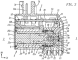
- the end surface of the solenoid portion 21, more specifically, the end surfaces of the bobbin 25 and the stationary iron core 26 near the second end 3, is pressed against the abutment portion 31b of the bonnet wall 31 from inside as illustrated in Figs. 3 and 4 . Accordingly, the valve actuation unit 20 and the valve body 10 are urged toward the first end 2 in the axial direction Ld by the resilient forces of the spring portions 31a.
- An upper fitting protrusion 31c protrudes upward from the upper edge of the abutment portion 31b of the bonnet wall 31, and a lower fitting protrusion 31d protrudes downward from the lower edge of the abutment portion 31b.
- an upper cutout recess 34b is recessed in the first and second upper bent portions 36 and 37 so as to straddle these bent portions at the edge of the top wall 34 of the magnetic cover 30 near the second end 3.
- an lower cutout recess 35b is recessed in the first and second lower bent portions 38 and 39 so as to straddle these bent portions at the edge of the bottom wall 35 near the second end 3.
- the upper fitting protrusion engages the upper cutout recess, and the lower fitting protrusion engages the lower cutout recess.
- the first upper bent portion 36 has first hook-receiving holes (first locking portions) 36a
- the second upper bent portion 37 has second hook-receiving holes (second locking portions) 37a.
- the first hook-receiving holes 36a and the second hook-receiving holes 37a are used when a first fastening member 51 is mounted on the top wall 34 of the magnetic cover 30 so as to straddle the upper parting line 34a, which will be described later.
- the first and second hook-receiving holes 36a and 37a are formed as oval holes elongated in the axial direction Ld. Two oval holes are formed side by side in the axial direction Ld in each of the first upper bent portion 36 and the second upper bent portion 37.
- a through-hole 35c is formed at the bottom wall 35 in the first lower bent portion 38 and the second lower bent portion 39 so as to straddle the lower parting line 35a.
- the through-hole 35c is used for positioning the solenoid valve when the solenoid valve is mounted onto a manifold or the like (not illustrated).
- the solenoid portion 21 of the valve actuation unit 20 is inserted into the magnetic cover 30 from the opening 30a thereof before the first fastening member 51 is attached to the magnetic cover 30.
- a pair of the locking tongues 30b of the magnetic cover 30 are gradually opened while the edges of the locking tongues 30b near the first end 2 are brought into contact with respective inclined surfaces 15a of the locking protrusions 15 of the valve body 10.
- the entire magnetic cover 30 is opened such that the magnetic cover 30 is separated at the parting lines 34a and 35a and the first and second sidewalls 32 and 33 are turnably opened with respective spring portions 31a of the bonnet wall 31 serving as pivots. This can reduce strain generation due to plastic deformation in the magnetic cover 30 as much as possible.
- the circuit unit 5 is mounted on the top wall 34 of the magnetic cover 30 as illustrated in Fig. 3 .
- the circuit unit 5 includes a circuit board spacer 51, a circuit board 52, and a connector cover 53.
- the circuit board spacer 51 is made of a synthetic resin and serves as the first fastening member that connects the first upper bent portion 36 and the second upper bent portion 37 to each other in the width direction Wd.
- the circuit board 52 is mounted on the circuit board spacer 51 and serves to supply electric power to the exciting coil 24.
- the connector cover 53 is made of a synthetic resin and serves as a second fastening member.
- the connector cover 53 is mounted on the top surface 13 of the valve body 10 and the top wall 34 of the magnetic cover 30 so as to straddle the top surface 13 and the top wall 34 and so as to entirely cover the circuit board spacer 51 and the circuit board 52, thereby connecting the circuit board spacer 51 and the valve body 10 to each other in the axial direction Ld.
- the circuit board spacer 51 includes a first mount surface 60, a circuit board mount surface 61, second mount surfaces 62a and 62b, a front end surface 64, and a rear end surface 65.
- the first mount surface 60 faces downward in the up-down direction Hd so as to oppose the top wall 34 of the magnetic cover.
- the circuit board mount surface 61 that faces upward is disposed opposite to the first mount surface 60.
- the second mount surfaces 62a and 62b stand upright from respective opposite ends of the first mount surface 60 in the width direction Wd.
- the front end surface 64 is an end surface near the second end 3 in the axial direction Ld
- the rear end surface 65 is an end surface near the first end 2.
- the front end surface 64 and the rear end surface 65 are disposed opposite to each other.
- the circuit board spacer 51 is formed as a cuboid elongated in the axial direction Ld and is bisymmetric with respect to the width direction Wd.
- First engagement portions 60a and second engagement portions 60b are formed on the first mount surface 60.
- the first engagement portions 60a and the second engagement portions 60b engage the first locking portions 36a and the second locking portions 37a of the magnetic cover 30, respectively. More specifically, the first and second engagement portions 60a and 60b protrude downward from the first mount surface 60, and the end portions of the first and second engagement portions 60a and 60b are bent toward the first end 2, which forms first and second L-shaped hooks.
- the first and second L-shaped hooks 60a and 60b are inserted into the first and second hook-receiving holes 36a and 37a (i.e., the first and second locking portions) and are slid toward first end 2.
- the first and second L-shaped hooks 60a and 60b thereby engage the inner peripheral edges, near first end 2, of the first and second hook-receiving holes 36a and 37a (see Fig. 3 ).
- first and second hook-receiving holes 36a and 37a two first L-shaped hooks 60a are formed on the first mount surface 60 side by side in the axial direction Ld, and two second L-shaped hooks 60b are also formed on the first mount surface 60 in the same manner.
- the circuit board spacer 51 is fixed to the top wall 34 of the magnetic cover 30.
- the circuit board spacer 51 fastens the first and second bent portions 36 and 37 of the top wall 34 to each other in the state of the engagement holes 30c of the magnetic cover 30 engaging the locking protrusions 15 of the valve body 10. This can prevent the magnetic cover 30 from opening at the upper parting line 34a of the top wall 34 and also at the lower parting line 35a, which can increase the fixation rigidity (i.e., rigidity of the assembly) between the magnetic cover 30 and the valve body 10.
- the circuit board mount surface 61 has a recess 61a recessed in a central portion thereof and has a support surface 61b that surrounds the recess 61a.
- a pair of positioning protrusions 61c are formed on the circuit board mount surface 61 so as to protrude upward from opposite corners, in the width direction Wd, of the support surface 61b at the edge thereof near the second end 3.
- Latching protrusions 63 are integrally formed on respective second mount surfaces 62a and 62b.
- the latching protrusions 63 serve as fourth locking portions that engage respective fourth engagement portions 74 of the connector cover 53.
- Each latching protrusion 63 includes an inclined surface 63a and an abutment surface 63b.
- the inclined surface 63a is raised from each of the second mount surfaces 62a and 62b in such a manner that the height of the inclined surface 63a gradually increases from an upper portion thereof toward a lower portion.
- the abutment surface 63b is formed as the bottom surface of the latching protrusion 63 that faces downward.
- the abutment surface 63b stands upright from each of the second mount surfaces 62a and 62b.
- the circuit board 52 is shaped like a rectangle.
- the length of the circuit board 52 in the axial direction Ld is slightly smaller than that of the valve unit 4 and longer than that of the circuit board spacer 51.
- the length of the circuit board 52 in the width direction Wd is slightly smaller than that of the circuit board spacer 51.
- the circuit board 52 is placed on the circuit board mount surface 61 with the corners of the circuit board 52 near the second end 3 abutting the positioning protrusions 61c.
- An end portion of the circuit board 52 near the first end 2 is supported by a support surface 17a, which is the top surface of the support wall 17 of the valve body 10.
- the support surface 61b of the circuit board mount surface 61 and the support surface 17a of the support wall 17 are formed so as to have the same height in the up-down direction Hd, which enables the circuit board 52 to be supported parallel to the axis L.
- the circuit board 52 is electrically connected to a pair of coil terminals 28.
- a pair of connector pins 52a for supplying electric power are electrically connected to the circuit board 52.
- the coil terminals 28 are arrayed in the width direction Wd, and so are the connector pins 52a.
- the coil terminals 28 are connected to the circuit board 52 from below at positions near the first end 2, and the connector pins 52a stand upward from the circuit board 52 at positions near the second end 3.
- the stationary iron core 26 attracts the movable iron core 22 due to the excitation of the exciting coil 24 and moves the movable iron core 22 toward the second end 3, which cuts off the communication between the output port P2 and the gas discharge port P3 and simultaneously establishes the communication between the output port P2 and the gas supply port P1.
- the stationary iron core 26 ceases to attract the movable iron core 22, which thereby cuts off the communication between the output port P2 and the gas supply port P1 and simultaneously establishes the communication between the output port P2 and the gas discharge port P3.
- the connector cover 53 which serves as the second fastening member, is a hollow cover with an open bottom and a closed top.
- the connector cover 53 is formed of an annular peripheral wall 70 and an upper wall 75 that covers the upper end of the peripheral wall 70.
- the connector cover 53 is fixed to the valve unit 4 while the connector cover 53 engages the valve body 10 and the circuit board spacer 51 so as to entirely cover the circuit board spacer 51 and the circuit board 52 while a lower end surface 71 of the peripheral wall 70 abuts a peripheral portion of the top surface of the valve unit 4.
- the peripheral wall 70 of the connector cover 53 has a first side wall portion 72a and a second side wall portion 72b that are positioned at opposite sides in the width direction Wd and face in opposite directions.
- a pair of the first side wall portion 72a and the second side wall portion 72b are connected to each other at top ends thereof by the upper wall 75.
- a first latching window (third engagement portion) 73 is formed through each of the first and second side wall portions 72a and 72b at a position near the first end 2.
- Each first latching window 73 serves to engage the corresponding latching hook (third locking portion) 16 of the valve body 10.
- a second latching window (fourth engagement portion) 74 is formed through each of the first and second side walls 72a and 72b at a position near the second end 3.
- Each second latching window 74 serves to engage the corresponding latching protrusion (fourth locking portion) 63 of the circuit board spacer.
- Each of the latching hooks 16 of the valve body 10 has an end portion that is bent outward so as to be shaped like the letter L, and the end portion has an inclined surface 16a inclined downward toward the end thereof and an abutment surface 16b facing downward.
- Each first latching window 73 of the connector cover has an inner peripheral edge 73a that faces upward, and the inner peripheral edge 73a abuts the abutment surface 16b of the corresponding latching hook 16, thereby causing the latching hook (third locking portion) 16 and the first latching window (third engagement portion) 73 to engage each other.
- the length of the latching hook 16 in axial direction Ld is the same as that of the first latching window 73 in axial direction Ld.
- Each second latching window 74 of the connector cover has an inner peripheral edge 74a that faces upward, and the inner peripheral edge 74a abuts the abutment surface 63b of the corresponding latching protrusion 63 of the circuit board spacer 51, thereby causing the latching protrusion (fourth locking portion) 63 of the circuit board spacer 51 and the second latching window (fourth engagement portion) 74 to engage each other.
- the length of the latching protrusion 63 in the axial direction Ld is the same as that of the second latching window 74 in the axial direction Ld.
- Recesses 71a and 71b for detaching the connector cover 53 are formed at a lower end surface 71 of the connector cover 53 at positions right below the first and second latching windows 73 and 74.
- the recesses 71a and 71b are used to open the first side wall portion 72a and the second side wall portion 72b outward and release the third and fourth engagement portions 73 and 74 from the engagement with the third and fourth locking portions 16 and 63.
- a pair of the connector pins 52a fixed to the circuit board 52 protrude upward through the upper wall 75 of the connector cover 53.
- a pair of adapter projections 76 also protrude from the upper wall 75 so as to interpose the connector pins 52a therebetween in the axial direction Ld.
- the adapter projections 76 are used to connect the connector pins 52a to external terminals.
- the height of the adapter projections 76 from the upper wall 75 is set to be greater than that of the connector pins 52a from the upper wall 75.
- the connector cover 53 serving as the second fastening member completes assembly of the solenoid valve 1A as depicted from the state of Fig. 11 to the state of Fig. 1 . More specifically, the circuit board spacer 51 is mounted on the magnetic cover 30 of the valve unit 4, and the circuit board 52 connected to the exciting coil 24 is subsequently mounted thereon. The connector cover 53 is mounted so as to cover the circuit board spacer 51 and the circuit board 52.
- the first and second side wall portions 72a and 72b of the connector cover 53 are gradually opened due to elastic deformation of the synthetic resin while the lower end surface 71 of the connector cover 53 is brought into contact with the inclined surfaces 16a of the latching hooks 16 and the inclined surfaces 63a of the latching protrusions 63.
- the latching hooks 16 and latching protrusions 63 engage, and are latched on, the first and second latching windows 73 and 74 of the connector cover 53.
- the connector cover 53 that serves as the second fastening member joins the circuit board spacer 51 that serves as the first fastening member and the valve body 10 to each other in the axial direction Ld.
- the back sides of the latching hooks 16 are supported by the support wall 17, which reduces the likelihood of the latching hooks 16 falling inward (backward) when and after the connector cover 53 is mounted.
- the fixation rigidity i.e., rigidity of the assembly
- the outer width of the connector cover 53 is set to be equal to the outer width of the valve body 10 and also equal to the outer width of the magnetic cover 30.
- the side surfaces of the connector cover 53, the valve body 10, and the magnetic cover 30 are flush with each other. Accordingly, for example, in the case of the multiple solenoid valves 1A being arranged side by side on a manifold (not illustrated) in the width direction Wd, the solenoid valves 1A can be arranged without gaps therebetween.
- FIG. 12 A modification example of the solenoid valve 1A is illustrated in Figs. 12 and 13 .
- the main difference of a solenoid valve 1B of a modification example from the solenoid valve 1A resides in the extension direction of the connector pins, and other major configurations are the same. Accordingly, the following description focuses specifically on the difference. Similar elements are denoted by the same reference signs, and the duplicated descriptions of such elements are omitted.
- a pair of connector pin extension grooves 64a are formed at the front end surface 64 of the circuit board spacer 51 near the second end 3 in the axial direction Ld.
- the connector pin extension grooves 64a pass through the front end surface 64 in the axial direction Ld and also opens upward so as to enable a pair of the connector pins 52a to extend toward the second end 3.
- the connector pins 52a are formed so as to protrude toward the second end 3 from the end of the circuit board 52 near the second end 3 through respective connector pin extension grooves 64a.
- a pair of upper and lower adapter projections 76 are formed so as to protrude toward the second end 3 from the front wall 77 of the connector cover 53 near the second end 3 so that the connector pins 52a can be extended out of the connector cover 53 through the front wall 77 between the adapter projections 76.
- the protrusion and the hole may be replaced with each other, in other words, may be formed oppositely to what has been described in the above embodiment.
- the valve body 10 and the magnetic cover 30 are joined to each other by engagement between the locking protrusions 15 and the engagement holes 30c.
- the valve body 10 and the magnetic cover 30, however, may be joined to each other by forming slit-like holes serving as the engagement holes in the valve body 10, and portions of the locking tongues 30b of the magnetic cover 30, which serve as the locking protrusions, may be caulked into respective engagement holes.
Landscapes
- Engineering & Computer Science (AREA)
- General Engineering & Computer Science (AREA)
- Mechanical Engineering (AREA)
- Physics & Mathematics (AREA)
- Electromagnetism (AREA)
- Magnetically Actuated Valves (AREA)
- Valve Housings (AREA)
- Valve Device For Special Equipments (AREA)
Abstract
Description
- The present invention relates to a solenoid valve that switches a communication state among multiple ports by displacing a movable iron core due to the magnetic excitation of a solenoid portion and by moving a valve plug due to the displacement of the movable iron core.
- A known solenoid valve is configured such that magnetic excitation of a solenoid portion of a valve actuation unit displaces a movable iron core, thereby moves a valve plug in the displacement direction of the movable iron core, and switches a communication state among multiple ports.
- A solenoid valve of this type, which is disclosed in PTL 1, includes a valve body in which the valve plug is accommodated and a closed-end magnetic cover that has an opening at one end. The solenoid portion of the valve actuation unit is inserted in the magnetic cover from the opening thereof. The valve body and the magnetic cover are joined to each other while a pair of engagement holes formed at opposite sidewalls of the magnetic cover at the opening engage a pair of respective locking protrusions formed at opposite side surfaces of the valve body.
- When the engagement holes of the magnetic cover engage the locking protrusions of the valve body in assembling the solenoid valve, the sidewalls of the magnetic cover at the opening temporarily run up onto the locking protrusions before engagement. This may cause plastic deformation of the magnetic cover and may lead to a decrease in a fixation rigidity between the valve body and the magnetic cover after assembly, which may cause play therebetween, for example.
- To prevent the plastic deformation from occurring during assembly, the magnetic cover may be formed, by pressing a sheet of a magnetic metal, such as stainless steel, so as to include a bonnet wall having spring portions. The bonnet wall having the spring portions is integrally connected to edges of the sidewalls that are positioned opposite to the opening of the magnetic cover. Accordingly, when the sidewalls of the magnetic cover are opened due to the sidewalls at the opening running up onto the locking protrusions of the valve body, the spring portions may urge respective sidewalls in the closing directions.
- This joining structure between the magnetic cover and the valve body, however, may not provide sufficient fixation rigidity therebetween because the fixation rigidity depends mainly on the rigidity of the spring portions of the connection wall.
- PTL 1: Japanese Unexamined Patent Application Publication No.
2017-207158 - Accordingly, a problem is to obtain sufficient fixation rigidity (i.e., rigidity of the assembly) between the valve body and the magnetic cover in the solenoid valve in which the valve body including the valve plug for switching the communication state among multiple ports is joined, by engagement of locking protrusions and engagement holes, to the magnetic cover that accommodates the solenoid portion of the valve actuation unit for moving the valve plug.
- To solve the above problem, the present invention provides a solenoid valve, which extends in an axial direction, a width direction orthogonal to the axial direction, and an up-down direction orthogonal to the axial direction and has a first end and a second end positioned opposite to each other in the axial direction. The solenoid valve includes a valve body having multiple ports inside and also having a valve plug disposed inside so as to be able to move in the axial direction and to switch a communication state among the ports. The solenoid valve also includes a valve actuation unit that includes a solenoid portion and that is connected to an end portion of the valve body near the second end and configured to move the valve plug by moving a movable iron core in the axial direction due to magnetic excitation of the solenoid portion. The solenoid valve also includes a closed-end magnetic cover having an opening at an end thereof near the first end. The solenoid valve is formed by inserting the solenoid portion into the magnetic cover from the opening and by joining the valve body and the magnetic cover to each other. The magnetic cover is formed into a box having the opening by bending a magnetic metal sheet. The magnetic cover has first and second sidewalls that extend in the axial direction and oppose each other in the width direction, a bonnet wall that integrally connects edges of the first and second sidewalls near the second end, a top wall formed in such a manner that first and second bent portion extending from respective axially extending upper edges of the first and second sidewalls are bent toward a space between the first and second sidewalls, and a bottom wall formed between axially extending lower edges of the first and second sidewalls so as to oppose the top wall in the up-down direction. The valve body and the magnetic cover are joined to each other by engagement between locking protrusions and engagement holes that are formed at a pair of side surfaces of the valve body and at the first and second sidewalls of the magnetic cover. The solenoid valve further includes a first fastening member that fastens the first and second bent portions to each other in the width direction, and a second fastening member that fastens the first fastening member and the valve body to each other in the axial direction.
- In the solenoid valve, it is preferable that the first bent portion have a first locking portion, the second bent portion have a second locking portion, and the valve body have a third locking portion. It is preferable that the first fastening member have a first engagement portion to engage the first locking portion of the first bent portion, a second engagement portion to engage the second locking portion of the second bent portion, and a fourth locking portion. It is also preferable that the second fastening member have a third engagement portion to engage the third locking portion of the valve body and a fourth engagement portion to engage the fourth locking portion of the first fastening member.
- In addition, it is more preferable that the locking protrusions protrude from respective side surfaces of the valve body that are positioned opposite to each other in the width direction and that the engagement holes be formed respectively at the first and second sidewalls at positions near the first end in the axial direction. The first fastening member preferably has a first mount surface that opposes the top wall of the magnetic cover formed of the first and second bent portions and also has a pair of second mount surfaces that stand upward from respective edges of the first mount surface that are opposite to each other in the width direction. The first engagement portion and the second engagement portion are preferably formed at the first mount surface, and the fourth locking portions are preferably formed at respective second mount surfaces.
- In the solenoid valve, it is still more preferable that the first and second engagement portions formed in the first fastening member protrude downward from the first mount surface and be formed as L-shaped hooks that are bent toward the first end. The first and second locking portions of the first and second bent portions are preferably formed as hook-receiving holes penetrating the first and second bent portions, and the L-shaped hooks preferably engage respective opening edges, near the first end, of the hook-receiving holes by inserting the L-shaped hooks into the hook-receiving holes and by sliding the L-shaped hooks toward the first end.
- Here, multiple sets of the first and second locking portions and multiple sets of the first and second engagement portions may be disposed in the axial direction.
- In the solenoid valve, it is still more preferable that the third locking portion of the valve body be formed as a pair of latching hooks that protrude from a top surface of the valve body at opposite end portions thereof in the width direction and that are bent so as to face in opposite directions. The second fastening member is preferably formed as a hollow cover having an opening at a bottom thereof so as to cover the first fastening member. Latching windows that serve as the third engagement portion are preferably formed through a peripheral wall of the hollow cover at opposite positions in the width direction. In addition, a lower end surface of the peripheral wall of the hollow cover preferably abuts the top wall of the magnetic cover and the top surface of the valve body.
- Here, it is preferable that the latching hooks serving as the third locking portion be integrally connected to each other by a support wall formed therebetween and that a circuit board for actuating the valve actuation unit be accommodated in the hollow cover and the circuit board be supported by the first fastening member and the support wall.
- In the solenoid valve, the bonnet wall of the magnetic cover is preferably formed of a pair of spring portions that extend in the up-down direction and are connected to respective edges of the first and second sidewalls near the second end and also of an abutment portion that connects the spring portions to each other. The spring portions are preferably formed as curved walls that bulge out toward the second end from respective opposite end portions of the abutment portion in the width direction, and an end surface of the solenoid portion near the second end is preferably pressed against the abutment portion of the bonnet wall from inside.
- As described above, the solenoid valve of the present invention is formed by joining the valve body that includes the valve plug configured to switch the communication state among multiple ports to the magnetic cover that accommodates the solenoid portion of the valve actuation unit for moving the valve plug. In the solenoid valve, the magnetic cover is formed as a box by bending a magnetic metal sheet. The first and second bent portions extend from axially extending upper edges of a pair of respective sidewalls, and the top wall of the magnetic cover is formed by bending the first and second bent portions toward a space therebetween. The valve body and the magnetic cover are joined to each other by engagement between the locking protrusions and the engagement holes that are formed at a pair of the side surfaces of the valve body and at a pair of the sidewalls of the magnetic cover. The first fastening member fastens the first and second bent portions to each other in the width direction, and the second fastening member fastens the first fastening member and the valve body to each other in the axial direction.
- This makes the engagement between the engagement holes and the locking protrusions more reliable, which can produce sufficient fixation rigidity (rigidity of the assembly) between the valve body and the magnetic cover.
-
- [
Fig. 1] Fig. 1 is a perspective view illustrating a solenoid valve according to an embodiment of the present invention when the solenoid valve is viewed obliquely from above. - [
Fig. 2] Fig. 2 is a perspective view illustrating the solenoid valve of the embodiment of the present invention when the solenoid valve is viewed obliquely from below. - [
Fig. 3] Fig. 3 is a vertical section of the solenoid valve ofFig. 1 , which is taken along the axis of the solenoid valve. - [
Fig. 4] Fig. 4 is a horizontal section of the solenoid valve ofFig. 1 , which is taken along the axis of the solenoid valve. - [
Fig. 5] Fig. 5 is an exploded perspective view illustrating the solenoid valve of the present invention in which a magnetic cover is detached from a valve unit. - [
Fig. 6] Fig. 6 is a perspective view illustrating the entire valve unit of the solenoid valve according to the present invention. - [
Figs. 7] Figs. 7 are perspective views illustrating the magnetic cover ofFig. 5 when the magnetic cover is viewed obliquely from above inFig. 7(a) and obliquely from below inFig. 7(b) . - [
Fig. 8] Fig. 8 is an exploded perspective view for explaining a procedure of mounting a circuit board spacer (a first fastening member) onto the valve unit ofFig. 6 . - [
Fig. 9] Fig. 9 is a perspective view illustrating a state in which the circuit board spacer is mounted on the valve unit in accordance with the procedure ofFig. 8 . - [
Fig. 10] Fig. 10 is a perspective view illustrating the circuit board spacer ofFig. 8 . - [
Fig. 11] Fig. 11 is an exploded perspective view illustrating a state in which a connector cover is detached from the solenoid valve ofFig. 1 . - [
Fig. 12] Fig. 12 is a perspective view illustrating a modification example of the solenoid valve illustrated inFigs. 1 and 2 when the solenoid valve is viewed obliquely from above. - [
Fig. 13] Fig. 13 is a perspective view illustrating the modification example of the solenoid valve illustrated inFigs. 1 and 2 when the solenoid valve is viewed obliquely from below. - A
solenoid valve 1A according to an embodiment of the present invention will be described in detail with reference toFigs. 1 to 11 . - As illustrated in
Figs. 1 to 4 , thesolenoid valve 1A has an axial direction Ld, a width direction Wd, and an up-down direction Hd that are orthogonal to each other. Thesolenoid valve 1A has afirst end 2 and asecond end 3 that are opposite to each other in the axial direction Ld. Thesolenoid valve 1A includes avalve unit 4 and acircuit unit 5 for actuating thevalve unit 4. Thecircuit unit 5 is connected to an upper portion of thevalve unit 4 in the up-down direction Hd. Thesolenoid valve 1A has a bisymmetric appearance with respect to the width direction Wd. - As illustrated
Figs. 1 to 6 , thevalve unit 4 has multiple ports, in other words, ports P1 to P3. Thevalve unit 4 includes avalve body 10, avalve actuation unit 20, and amagnetic cover 30. Thevalve body 10 is made of a synthetic resin and has avalve plug 11 that is disposed therein so as to be able to move in the axial direction Ld and thereby switch the communication state among the ports P1 to P3. Thevalve actuation unit 20 is configured to move amovable iron core 22 in the axial direction Ld due to the magnetic excitation of asolenoid portion 21 and thereby move thevalve plug 11 between positions for switching the communication state among the ports P1 to P3. Themagnetic cover 30 is a closed-end cover having anopening 30a (seeFig. 7 ) formed at a position closer to thefirst end 2 in the axial direction Ld. Thevalve actuation unit 20 is connected to an end portion of thevalve body 10 near thesecond end 3 in the axial direction Ld, and thesolenoid portion 21 of thevalve actuation unit 20 is inserted in themagnetic cover 30 from itsopening 30a. Themagnetic cover 30 and thevalve body 10 are joined to each other in this manner. In other words, thevalve body 10, thevalve actuation unit 20, and themagnetic cover 30 are connected to each other in series in the axial direction Ld. - The
valve body 10 has a first and second side surfaces 12a and 12b that extend in the axial direction Ld and in the up-down direction Hd and are disposed opposite to each other with an axis L interposed therebetween. Thevalve body 10 also has top andbottom surfaces valve body 10 has a bisymmetric shape with respect to the width direction Wd. Lockingprotrusions 15 are formed so as to protrude from respective first and second side surfaces 12a and 12b. The lockingprotrusions 15 serve for connection with themagnetic cover 30. Thevalve body 10 also has a pair of latching hooks (third locking portions) 16 that protrude from opposite end portions of thetop surface 13 in the width direction Wd so as to face in opposite directions. The latching hooks 16 serve for connection with thecircuit unit 5. Rear surfaces of respective latching hooks 16 are integrally connected to each other by asupport wall 17 that protrudes from thetop surface 13 between the rear surfaces. Multiple ports, in other words, a gas supply port P1, an output port P2, and a gas discharge port P3, are formed at thebottom surface 14 so as to be arranged in this order from thefirst end 2 toward thesecond end 3 in the axial direction Ld. - As illustrated in
Figs. 3 and4 , avalve chamber 40 is formed inside thevalve body 10 so as to communicate with the gas supply port P1, the output port P2, and the gas discharge port P3. - A
first valve seat 41 and asecond valve seat 42 are formed in thevalve chamber 40. Thefirst valve seat 41 and thesecond valve seat 42 are disposed so as to oppose each other on the axis L with thevalve plug 11 interposed therebetween. Thevalve plug 11 is brought into contact with and moved away from thefirst valve seat 41 and thesecond valve seat 42. Thefirst valve seat 41 is formed at awall surface 43 of thevalve chamber 40, which is a surface closer to thefirst end 2, so as to protrude toward thesecond end 3. Agas supply hole 44 is formed through thefirst valve seat 41 and opens at thewall surface 43 on the axis L. Thegas supply hole 44 is connected to a gassupply communication channel 45 that is in communication with the gas supply port P1. - On the other hand, the
second valve seat 42 is formed in aretainer 46 that is fitted in thevalve chamber 40 at a position closer than thevalve plug 11 to thesecond end 3. Theretainer 46 is made of a resin material and has an outerannular portion 46a that is fitted gas-tightly into the inner peripheral wall of thevalve chamber 40. Theretainer 46 also has aprotrusion 46b that is disposed at a position surrounded by the outerannular portion 46a so as to protrude toward thefirst end 2. - The
protrusion 46b of theretainer 46 has agas discharge hole 47 formed so as to extend in the axial direction Ld and to communicate with the gas discharge port P3. The annularly shapedsecond valve seat 42 is formed at an end portion of theprotrusion 46b so as to surround thegas discharge hole 47. Two seal members S are fitted around the outerannular portion 46a so as to seal the gap between the outerannular portion 46a and the inner peripheral wall of thevalve chamber 40. Anannular groove 48 is formed in the outerannular portion 46a at a position between the two seal members S in the axial direction Ld so as to communicate with the gas discharge port P3. Theannular groove 48 is in communication with thegas discharge hole 47 through a gasdischarge communication channel 49 formed inside theretainer 46, which thereby enables thevalve chamber 40 to communicate with the gas discharge port P3. Note that the output port P2 is in continuous communication with thevalve chamber 40. - The
retainer 46 has a pair ofinsertion holes 46c formed between theprotrusion 46b and the outerannular portion 46a. A pair ofsupport arms 23 of themovable iron core 22 are inserted into theinsertion holes 46c. Thevalve plug 11, which is a poppet-type plug, is accommodated in thevalve chamber 40 at a position between thefirst valve seat 41 and thesecond valve seat 42. Thevalve plug 11 is supported between thesupport arms 23 of themovable iron core 22 so as to be able to slide in the axial direction Ld. - The
valve plug 11 is made of a resin material, such as rubber, having both elasticity and sealing properties. Thevalve plug 11 is brought into contact with and moved away from thefirst valve seat 41 and thesecond valve seat 42, thereby switching the communication state among the ports P1 to P3. Anelastic member 50 formed of a coil spring is compressedly disposed between thevalve plug 11 and theretainer 46 that is fixed to thevalve body 10. Accordingly, thevalve plug 11 is continuously urged toward thefirst valve seat 41 due to the resilient force of theelastic member 50. When thesolenoid portion 21 is not in an excited state, the urging force of theelastic member 50 causes thevalve plug 11 to be seated on thefirst valve seat 41. - Next, the
valve actuation unit 20 is described. Thevalve actuation unit 20 includes thesolenoid portion 21, themovable iron core 22, and themagnetic cover 30. Thesolenoid portion 21 is formed by fitting astationary iron core 26, in the axial direction Ld from thesecond end 3, into thecentral hole 25a of abobbin 25 around which anexciting coil 24 is formed. Themovable iron core 22 is also fitted, in the axial direction Ld from thefirst end 2, into thecentral hole 25a of thebobbin 25 so as to be able to slide in the axial direction Ld. Themagnetic cover 30 is shaped like a box having a rectangular cross section. In the axial direction Ld, themagnetic cover 30 has theopening 30a near thefirst end 2, and a side of themagnetic cover 30 near thesecond end 3 is closed by abonnet wall 31. Thecentral hole 25a of thebobbin 25 has a substantially rectangular transverse cross section. Fitting portions of thestationary iron core 26 and themovable iron core 22, which are portions to be fitted to thecentral hole 25a, also have substantially rectangular transverse cross sections. The transverse periphery of thebobbin 25, on the other hand, is shaped like a rectangle having four round corners or shaped like a running track or the like. - A
magnetic ring 27 is disposed at an end portion of thebobbin 25 near thefirst end 2 so as to surround the opening of thecentral hole 25a. A pair ofcoil terminals 28 protrude radially outward from thebobbin 25 at positions closer than themagnetic ring 27, which is disposed at the end portion of thebobbin 25 near thefirst end 2, to thesecond end 3. Thecoil terminals 28 are electrically connected to theexciting coil 24. Thecoil terminals 28 protrude upward from thevalve unit 4 between themagnetic cover 30 and thevalve body 10. The seal members S seal a gap between thebonnet wall 31 and thebobbin 25 and also seal a gap between thebobbin 25 and themagnetic ring 27. - The
stationary iron core 26 is formed, using stamping, of a magnetic metal plate having a uniform thickness, and aflange 26a are integrally formed at an end of thestationary iron core 26 near thesecond end 3. Thestationary iron core 26 is held between thebobbin 25 and thebonnet wall 31 in the state of theflange 26a engaging the end portion of thebobbin 25 near thesecond end 3. - The
movable iron core 22 is also formed, using stamping, of a magnetic metal plate having a uniform thickness. Themovable iron core 22 has aniron core portion 22a slidably fitted in thecentral hole 25a of thebobbin 25 and also has a pair of thesupport arms 23 protruding in the axial direction Ld from the end surface of theiron core portion 22a near thefirst end 2. Thesupport arms 23 have the same length and protrude from respective end portions of the end surface of themovable iron core 22, the end portions being positioned opposite to each other in the up-down direction Hd (in other words, in the width direction). Thesupport arms 23 extend into thevalve chamber 40 through the above-describedinsertion holes 46c formed in theretainer 46, and thesupport arms 23 support thevalve plug 11 slidably in the axial direction Ld. - Hook-shaped cap-locking
fingers 23a are formed at respective end portions of thesupport arms 23 so as to be bent outward in opposite directions. Acap member 29 having a substantially U-shaped cross section is installed between the end portions of thesupport arms 23, and the cap-lockingfingers 23a lock thecap member 29 at the opposite ends thereof. Thecap member 29 is formed of a metal sheet having spring properties, and a valve-seat opening 29a is formed through thecap member 29 on the central axis L between thesupport arms 23. The valve-seat opening 29a is provided to allow thevalve plug 11 to be seated on thefirst valve seat 41. Accordingly, when themovable iron core 22 is moved toward thefirst end 2, thevalve plug 11 can be seated on thefirst valve seat 41 through the valve-seat opening 29a. On the other hand, when themovable iron core 22 is moved toward thesecond end 3, thecap member 29 presses thevalve plug 11 toward thesecond end 3 and thereby moves thevalve plug 11 away from thefirst valve seat 41 and seats thevalve plug 11 on thesecond valve seat 42. - In other words, in the present embodiment, when the
exciting coil 24 is energized (in the excited state), thestationary iron core 26 attracts and moves themovable iron core 22 together with thevalve plug 11 toward thesecond end 3. As a result, thevalve plug 11 is released from thefirst valve seat 41 and seated on thesecond valve seat 42, which causes the gas supply port P1 to communicate with the output port P2 throughvalve chamber 40. - On the other hand, when the
exciting coil 24 is not energized (in a magnetic neutral state), the urging force of theelastic member 50 moves themovable iron core 22 together with thevalve plug 11 away from thestationary iron core 26 toward thefirst end 2. As a result, thevalve plug 11 is released from thesecond valve seat 42 and seated on thefirst valve seat 41, which causes the output port P2 to communicate with the gas discharge port P3 throughvalve chamber 40. - As illustrated in
Fig. 7 , themagnetic cover 30 is formed as a box having a rectangular cross section by bending a magnetic metal plate using press forming or the like, in which the side near thefirst end 2 is open and the side near thesecond end 3 is closed. Themagnetic cover 30 has a bisymmetric shape with respect to the width direction Wd. Themagnetic cover 30 has first andsecond sidewalls magnetic cover 30 also has thebonnet wall 31 that extends perpendicular to the axis L and integrally connects end portions of the first andsecond sidewalls second end 3 to each other. Themagnetic cover 30 also has atop wall 34 and abottom wall 35 that extend parallel to the axis L between respective upper and lower edges of the first andsecond sidewalls magnetic cover 30 has a rectangular shape. - An first upper
bent portion 36 and an second upperbent portion 37 are formed so as to extend from respective upper edges of the first andsecond sidewalls bent portion 38 and a second lowerbent portion 39 are formed so as to extend from respective lower edges of the first andsecond sidewalls top wall 34 is formed such that the first upperbent portion 36 and the second upperbent portion 37 are bent toward the space between the first andsecond sidewalls upper parting line 34a. Similarly, thebottom wall 35 is formed such that the first lowerbent portion 38 and the second lowerbent portion 39 are bent toward the space between the first andsecond sidewalls lower parting line 35a. - The first and
second sidewalls top wall 34 and thebottom wall 35 and thereby form a pair of lockingtongues 30b. The lockingtongues 30b extend further toward thefirst end 2 from theopening 30a at which the top andbottom walls first end 2. Arectangular engagement hole 30c elongated in the up-down direction Hd is formed through each lockingtongue 30b. In other words, theengagement hole 30c engages each lockingprotrusion 15 of thevalve body 10, thereby joining thevalve body 10 and themagnetic cover 30 to each other. The length of eachengagement hole 30c in the up-down direction Hd is the same as the length of each lockingprotrusion 15 in the up-down direction Hd. - More specifically, as illustrated in
Figs. 4 to 6 , each lockingprotrusion 15 has aninclined surface 15a and anabutment surface 15b. Theinclined surface 15a is raised from each of the side surfaces 12a and 12b in such a manner that the height of theinclined surface 15a gradually increases from the edge thereof near thesecond end 3 to the edge near thefirst end 2. Theabutment surface 15b is formed so as to stand upright from each of the side surfaces 12a and 12b and so as to face thefirst end 2. Eachengagement hole 30c has an innerperipheral edge 30d positioned closer to thefirst end 2 and facing thesecond end 3, and the innerperipheral edge 30d abuts theabutment surface 15b, thereby causing theengagement hole 30c to engage the lockingprotrusion 15 of thevalve body 10. The width of thevalve body 10 near the locking protrusions 15 (i.e., the distance between thefirst side surface 12a and thesecond side surface 12b) is set to be equal to the inner width of themagnetic cover 30, in other words, equal to the distance between the first andsecond sidewalls tongues 30b. - The
bonnet wall 31 is formed of a pair ofspring portions 31a and anabutment portion 31b. Thespring portions 31a extend in the up-down direction Hd and are connected to respective edges, near thesecond end 3, of the first andsecond sidewalls abutment portion 31b connects thespring portions 31a to each other. Thespring portions 31a are formed of curved walls that bulge out toward thesecond end 3 from respective opposite end portions of theabutment portion 31b in the width direction Wd. The end surface of thesolenoid portion 21, more specifically, the end surfaces of thebobbin 25 and thestationary iron core 26 near thesecond end 3, is pressed against theabutment portion 31b of thebonnet wall 31 from inside as illustrated inFigs. 3 and4 . Accordingly, thevalve actuation unit 20 and thevalve body 10 are urged toward thefirst end 2 in the axial direction Ld by the resilient forces of thespring portions 31a. - An upper
fitting protrusion 31c protrudes upward from the upper edge of theabutment portion 31b of thebonnet wall 31, and a lowerfitting protrusion 31d protrudes downward from the lower edge of theabutment portion 31b. On the other hand, anupper cutout recess 34b is recessed in the first and second upperbent portions top wall 34 of themagnetic cover 30 near thesecond end 3. Similarly, anlower cutout recess 35b is recessed in the first and second lowerbent portions bottom wall 35 near thesecond end 3. The upper fitting protrusion engages the upper cutout recess, and the lower fitting protrusion engages the lower cutout recess. - In addition, in the
top wall 34 of themagnetic cover 30, the first upperbent portion 36 has first hook-receiving holes (first locking portions) 36a, and the second upperbent portion 37 has second hook-receiving holes (second locking portions) 37a. The first hook-receivingholes 36a and the second hook-receivingholes 37a are used when afirst fastening member 51 is mounted on thetop wall 34 of themagnetic cover 30 so as to straddle theupper parting line 34a, which will be described later. The first and second hook-receivingholes bent portion 36 and the second upperbent portion 37. In addition, a through-hole 35c is formed at thebottom wall 35 in the first lowerbent portion 38 and the second lowerbent portion 39 so as to straddle thelower parting line 35a. The through-hole 35c is used for positioning the solenoid valve when the solenoid valve is mounted onto a manifold or the like (not illustrated). - When the
valve body 10 and themagnetic cover 30 are joined to each other as from the state illustrated inFig. 5 to the state illustrated inFig. 6 , thesolenoid portion 21 of thevalve actuation unit 20 is inserted into themagnetic cover 30 from theopening 30a thereof before thefirst fastening member 51 is attached to themagnetic cover 30. Here, a pair of the lockingtongues 30b of themagnetic cover 30 are gradually opened while the edges of the lockingtongues 30b near thefirst end 2 are brought into contact with respectiveinclined surfaces 15a of the lockingprotrusions 15 of thevalve body 10. Here, it is not only the lockingtongues 30b that are opened. The entiremagnetic cover 30 is opened such that themagnetic cover 30 is separated at theparting lines second sidewalls respective spring portions 31a of thebonnet wall 31 serving as pivots. This can reduce strain generation due to plastic deformation in themagnetic cover 30 as much as possible. - Meanwhile, the
circuit unit 5 is mounted on thetop wall 34 of themagnetic cover 30 as illustrated inFig. 3 . Thecircuit unit 5 includes acircuit board spacer 51, acircuit board 52, and aconnector cover 53. Thecircuit board spacer 51 is made of a synthetic resin and serves as the first fastening member that connects the first upperbent portion 36 and the second upperbent portion 37 to each other in the width direction Wd. Thecircuit board 52 is mounted on thecircuit board spacer 51 and serves to supply electric power to theexciting coil 24. Theconnector cover 53 is made of a synthetic resin and serves as a second fastening member. Theconnector cover 53 is mounted on thetop surface 13 of thevalve body 10 and thetop wall 34 of themagnetic cover 30 so as to straddle thetop surface 13 and thetop wall 34 and so as to entirely cover thecircuit board spacer 51 and thecircuit board 52, thereby connecting thecircuit board spacer 51 and thevalve body 10 to each other in the axial direction Ld. - As illustrated in
Figs. 8 to 10 , thecircuit board spacer 51 includes afirst mount surface 60, a circuitboard mount surface 61, second mount surfaces 62a and 62b, afront end surface 64, and arear end surface 65. Thefirst mount surface 60 faces downward in the up-down direction Hd so as to oppose thetop wall 34 of the magnetic cover. The circuitboard mount surface 61 that faces upward is disposed opposite to thefirst mount surface 60. The second mount surfaces 62a and 62b stand upright from respective opposite ends of thefirst mount surface 60 in the width direction Wd. Thefront end surface 64 is an end surface near thesecond end 3 in the axial direction Ld, and therear end surface 65 is an end surface near thefirst end 2. Thefront end surface 64 and therear end surface 65 are disposed opposite to each other. Thecircuit board spacer 51 is formed as a cuboid elongated in the axial direction Ld and is bisymmetric with respect to the width direction Wd. -
First engagement portions 60a andsecond engagement portions 60b are formed on thefirst mount surface 60. Thefirst engagement portions 60a and thesecond engagement portions 60b engage thefirst locking portions 36a and thesecond locking portions 37a of themagnetic cover 30, respectively. More specifically, the first andsecond engagement portions first mount surface 60, and the end portions of the first andsecond engagement portions first end 2, which forms first and second L-shaped hooks. The first and second L-shapedhooks holes first end 2. The first and second L-shapedhooks first end 2, of the first and second hook-receivingholes Fig. 3 ). As is the case for the first and second hook-receivingholes hooks 60a are formed on thefirst mount surface 60 side by side in the axial direction Ld, and two second L-shapedhooks 60b are also formed on thefirst mount surface 60 in the same manner. - Thus, the
circuit board spacer 51 is fixed to thetop wall 34 of themagnetic cover 30. At the same time, thecircuit board spacer 51 fastens the first and secondbent portions top wall 34 to each other in the state of the engagement holes 30c of themagnetic cover 30 engaging the lockingprotrusions 15 of thevalve body 10. This can prevent themagnetic cover 30 from opening at theupper parting line 34a of thetop wall 34 and also at thelower parting line 35a, which can increase the fixation rigidity (i.e., rigidity of the assembly) between themagnetic cover 30 and thevalve body 10. - The circuit
board mount surface 61 has arecess 61a recessed in a central portion thereof and has asupport surface 61b that surrounds therecess 61a. A pair of positioningprotrusions 61c are formed on the circuitboard mount surface 61 so as to protrude upward from opposite corners, in the width direction Wd, of thesupport surface 61b at the edge thereof near thesecond end 3. - Latching
protrusions 63 are integrally formed on respective second mount surfaces 62a and 62b. The latchingprotrusions 63 serve as fourth locking portions that engage respectivefourth engagement portions 74 of theconnector cover 53. Each latchingprotrusion 63 includes aninclined surface 63a and anabutment surface 63b. Theinclined surface 63a is raised from each of the second mount surfaces 62a and 62b in such a manner that the height of theinclined surface 63a gradually increases from an upper portion thereof toward a lower portion. Theabutment surface 63b is formed as the bottom surface of the latchingprotrusion 63 that faces downward. Theabutment surface 63b stands upright from each of the second mount surfaces 62a and 62b. - As illustrated in
Figs. 3 and11 , thecircuit board 52 is shaped like a rectangle. The length of thecircuit board 52 in the axial direction Ld is slightly smaller than that of thevalve unit 4 and longer than that of thecircuit board spacer 51. The length of thecircuit board 52 in the width direction Wd is slightly smaller than that of thecircuit board spacer 51. Thecircuit board 52 is placed on the circuitboard mount surface 61 with the corners of thecircuit board 52 near thesecond end 3 abutting thepositioning protrusions 61c. An end portion of thecircuit board 52 near thefirst end 2 is supported by asupport surface 17a, which is the top surface of thesupport wall 17 of thevalve body 10. Here, thesupport surface 61b of the circuitboard mount surface 61 and thesupport surface 17a of thesupport wall 17 are formed so as to have the same height in the up-down direction Hd, which enables thecircuit board 52 to be supported parallel to the axis L. - The
circuit board 52 is electrically connected to a pair ofcoil terminals 28. A pair ofconnector pins 52a for supplying electric power are electrically connected to thecircuit board 52. Thecoil terminals 28 are arrayed in the width direction Wd, and so are the connector pins 52a. Thecoil terminals 28 are connected to thecircuit board 52 from below at positions near thefirst end 2, and the connector pins 52a stand upward from thecircuit board 52 at positions near thesecond end 3. - When electric power is supplied to the
exciting coil 24 through the connector pins 52a, thecircuit board 52, and thecoil terminals 28, thestationary iron core 26 attracts themovable iron core 22 due to the excitation of theexciting coil 24 and moves themovable iron core 22 toward thesecond end 3, which cuts off the communication between the output port P2 and the gas discharge port P3 and simultaneously establishes the communication between the output port P2 and the gas supply port P1. On the contrary, when electric power supplied to theexciting coil 24 is cut off and theexciting coil 24 becomes magnetically neutral, thestationary iron core 26 ceases to attract themovable iron core 22, which thereby cuts off the communication between the output port P2 and the gas supply port P1 and simultaneously establishes the communication between the output port P2 and the gas discharge port P3. - The
connector cover 53, which serves as the second fastening member, is a hollow cover with an open bottom and a closed top. Theconnector cover 53 is formed of an annularperipheral wall 70 and anupper wall 75 that covers the upper end of theperipheral wall 70. Theconnector cover 53 is fixed to thevalve unit 4 while theconnector cover 53 engages thevalve body 10 and thecircuit board spacer 51 so as to entirely cover thecircuit board spacer 51 and thecircuit board 52 while alower end surface 71 of theperipheral wall 70 abuts a peripheral portion of the top surface of thevalve unit 4. - More specifically, the
peripheral wall 70 of theconnector cover 53 has a firstside wall portion 72a and a secondside wall portion 72b that are positioned at opposite sides in the width direction Wd and face in opposite directions. A pair of the firstside wall portion 72a and the secondside wall portion 72b are connected to each other at top ends thereof by theupper wall 75. A first latching window (third engagement portion) 73 is formed through each of the first and secondside wall portions first end 2. Each first latchingwindow 73 serves to engage the corresponding latching hook (third locking portion) 16 of thevalve body 10. A second latching window (fourth engagement portion) 74 is formed through each of the first andsecond side walls second end 3. Eachsecond latching window 74 serves to engage the corresponding latching protrusion (fourth locking portion) 63 of the circuit board spacer. - Each of the latching hooks 16 of the
valve body 10 has an end portion that is bent outward so as to be shaped like the letter L, and the end portion has aninclined surface 16a inclined downward toward the end thereof and anabutment surface 16b facing downward. Each first latchingwindow 73 of the connector cover has an innerperipheral edge 73a that faces upward, and the innerperipheral edge 73a abuts theabutment surface 16b of thecorresponding latching hook 16, thereby causing the latching hook (third locking portion) 16 and the first latching window (third engagement portion) 73 to engage each other. The length of the latchinghook 16 in axial direction Ld is the same as that of thefirst latching window 73 in axial direction Ld. - Each
second latching window 74 of the connector cover has an innerperipheral edge 74a that faces upward, and the innerperipheral edge 74a abuts theabutment surface 63b of the corresponding latchingprotrusion 63 of thecircuit board spacer 51, thereby causing the latching protrusion (fourth locking portion) 63 of thecircuit board spacer 51 and the second latching window (fourth engagement portion) 74 to engage each other. The length of the latchingprotrusion 63 in the axial direction Ld is the same as that of thesecond latching window 74 in the axial direction Ld.Recesses connector cover 53 are formed at alower end surface 71 of theconnector cover 53 at positions right below the first andsecond latching windows recesses side wall portion 72a and the secondside wall portion 72b outward and release the third andfourth engagement portions fourth locking portions - A pair of the connector pins 52a fixed to the
circuit board 52 protrude upward through theupper wall 75 of theconnector cover 53. A pair ofadapter projections 76 also protrude from theupper wall 75 so as to interpose the connector pins 52a therebetween in the axial direction Ld. Theadapter projections 76 are used to connect the connector pins 52a to external terminals. The height of theadapter projections 76 from theupper wall 75 is set to be greater than that of the connector pins 52a from theupper wall 75. - Mounting the
connector cover 53 serving as the second fastening member completes assembly of thesolenoid valve 1A as depicted from the state ofFig. 11 to the state ofFig. 1 . More specifically, thecircuit board spacer 51 is mounted on themagnetic cover 30 of thevalve unit 4, and thecircuit board 52 connected to theexciting coil 24 is subsequently mounted thereon. Theconnector cover 53 is mounted so as to cover thecircuit board spacer 51 and thecircuit board 52. Here, the first and secondside wall portions connector cover 53 are gradually opened due to elastic deformation of the synthetic resin while thelower end surface 71 of theconnector cover 53 is brought into contact with theinclined surfaces 16a of the latching hooks 16 and theinclined surfaces 63a of the latchingprotrusions 63. The latching hooks 16 and latchingprotrusions 63 engage, and are latched on, the first andsecond latching windows connector cover 53. Thus, theconnector cover 53 that serves as the second fastening member joins thecircuit board spacer 51 that serves as the first fastening member and thevalve body 10 to each other in the axial direction Ld. Here, the back sides of the latching hooks 16 are supported by thesupport wall 17, which reduces the likelihood of the latching hooks 16 falling inward (backward) when and after theconnector cover 53 is mounted. - This can increase the joining strength in the axial direction Ld between the
magnetic cover 30 engaging thecircuit board spacer 51 and thevalve body 10. Thus, in combination with an increase in the joining strength due to thecircuit board spacer 51 as described above, the fixation rigidity (i.e., rigidity of the assembly) between themagnetic cover 30 and thevalve body 10 can be further improved. In addition, as illustrated inFigs. 1 and 2 , in the solenoid valve lAin which thevalve unit 4 and thecircuit unit 5 are joined to each other, the outer width of theconnector cover 53 is set to be equal to the outer width of thevalve body 10 and also equal to the outer width of themagnetic cover 30. In other words, the side surfaces of theconnector cover 53, thevalve body 10, and themagnetic cover 30 are flush with each other. Accordingly, for example, in the case of themultiple solenoid valves 1A being arranged side by side on a manifold (not illustrated) in the width direction Wd, thesolenoid valves 1A can be arranged without gaps therebetween. - A modification example of the
solenoid valve 1A is illustrated inFigs. 12 and 13 . The main difference of asolenoid valve 1B of a modification example from thesolenoid valve 1A resides in the extension direction of the connector pins, and other major configurations are the same. Accordingly, the following description focuses specifically on the difference. Similar elements are denoted by the same reference signs, and the duplicated descriptions of such elements are omitted. - As illustrated in
Figs. 8 to 10 , a pair of connectorpin extension grooves 64a are formed at thefront end surface 64 of thecircuit board spacer 51 near thesecond end 3 in the axial direction Ld. The connectorpin extension grooves 64a pass through thefront end surface 64 in the axial direction Ld and also opens upward so as to enable a pair of the connector pins 52a to extend toward thesecond end 3. The connector pins 52a are formed so as to protrude toward thesecond end 3 from the end of thecircuit board 52 near thesecond end 3 through respective connectorpin extension grooves 64a. A pair of upper andlower adapter projections 76 are formed so as to protrude toward thesecond end 3 from thefront wall 77 of theconnector cover 53 near thesecond end 3 so that the connector pins 52a can be extended out of theconnector cover 53 through thefront wall 77 between theadapter projections 76. - One embodiment of the solenoid valve according to the present invention has been described in detail. It should be understood that the present invention is not limited to the embodiment described above and may be subjected to various design changes without departing from the scope and spirit of the invention set forth in the claims.
- For example, in each pair of the locking portion and the engagement portion, the protrusion and the hole may be replaced with each other, in other words, may be formed oppositely to what has been described in the above embodiment. For example, it has been described that the
valve body 10 and themagnetic cover 30 are joined to each other by engagement between the lockingprotrusions 15 and theengagement holes 30c. Thevalve body 10 and themagnetic cover 30, however, may be joined to each other by forming slit-like holes serving as the engagement holes in thevalve body 10, and portions of the lockingtongues 30b of themagnetic cover 30, which serve as the locking protrusions, may be caulked into respective engagement holes. -
- 1A, 1B
- solenoid valve
- 2
- first end
- 3
- second end
- 4
- valve unit
- 5
- circuit unit
- 10
- valve body
- 11
- valve plug
- 12a
- first side surface
- 12b
- second side surface
- 13
- top surface
- 15
- locking protrusion
- 16
- latching hook (third locking portion)
- 17
- support wall
- 17a
- support surface
- 20
- valve actuation unit
- 21
- solenoid portion
- 22
- movable iron core
- 24
- exciting coil
- 25
- bobbin
- 26
- stationary iron core
- 30
- magnetic cover
- 30a
- opening
- 30b
- locking tongue
- 30c
- engagement hole
- 31
- bonnet wall
- 31a
- spring portion
- 31b
- abutment portion
- 32
- first sidewall
- 33
- second sidewall
- 34
- top wall
- 34a
- upper parting line
- 36
- first upper bent portion
- 36a
- first hook-receiving hole (first locking portion)
- 37
- second upper bent portion
- 37a
- second hook-receiving hole (second locking portion)
- 51
- circuit board spacer (first fastening member)
- 52
- circuit board
- 52a
- connector pin
- 53
- connector cover (hollow cover, second fastening member)
- 60
- first mount surface
- 60a
- first L-shaped hook (first engagement portion)
- 60b
- second L-shaped hook (second engagement portion)
- 61
- circuit board mount surface
- 62a, 62b
- second mount surface
- 63
- latching protrusion (fourth locking portion)
- 70
- peripheral wall
- 71
- lower end surface
- 72a
- first side wall
- 72b
- second side wall
- 73
- first latching window (third engagement portion)
- 74
- second latching window (fourth engagement portion)
- Ld
- axial direction
- Hd
- up-down direction
- Wd
- width direction
- P1
- gas supply port
- P2
- output port
- P3
- gas discharge port
Claims (9)
- A solenoid valve that extends in an axial direction, a width direction orthogonal to the axial direction, and an up-down direction orthogonal to the axial direction and that has a first end and a second end positioned opposite to each other in the axial direction, the solenoid valve comprising:a valve body having multiple ports formed inside and also having a valve plug disposed inside so as to be able to move in the axial direction and switch a communication state among the ports;a valve actuation unit that includes a solenoid portion and that is connected to an end portion of the valve body near the second end and configured to move the valve plug by moving a movable iron core in the axial direction due to magnetic excitation of the solenoid portion; anda closed-end magnetic cover having an opening at an end thereof near the first end, whereinthe solenoid valve is formed by inserting the solenoid portion into the magnetic cover from the opening and by joining the valve body and the magnetic cover to each other,the magnetic cover is formed into a box having the opening by bending a magnetic metal sheet and hasfirst and second sidewalls that extend in the axial direction and oppose each other in the width direction,a bonnet wall that integrally connects edges of the first and second sidewalls near the second end,a top wall formed in such a manner that first and second bent portion extending from respective axially extending upper edges of the first and second sidewalls are bent toward a space between the first and second sidewalls, anda bottom wall formed between axially extending lower edges of the first and second sidewalls so as to oppose the top wall in the up-down direction,the valve body and the magnetic cover are joined to each other by engagement between locking protrusions and engagement holes that are formed at a pair of side surfaces of the valve body and at the first and second sidewalls of the magnetic cover, andthe solenoid valve further includesa first fastening member that fastens the first and second bent portions to each other in the width direction anda second fastening member that fastens the first fastening member and the valve body to each other in the axial direction.
- The solenoid valve according to Claim 1, wherein
the first bent portion has a first locking portion, the second bent portion has a second locking portion, and the valve body has a third locking portion,
the first fastening member has a first engagement portion to engage the first locking portion of the first bent portion, a second engagement portion to engage the second locking portion of the second bent portion, and a fourth locking portion, and
the second fastening member has a third engagement portion to engage the third locking portion of the valve body and a fourth engagement portion to engage the fourth locking portion of the first fastening member. - The solenoid valve according to Claim 2, wherein
the locking protrusions protrude from respective side surfaces of the valve body that are positioned opposite to each other in the width direction, and the engagement holes are formed respectively at the first and second sidewalls at positions near the first end in the axial direction,
the first fastening member has a first mount surface that opposes the top wall of the magnetic cover formed of the first and second bent portions and also has a pair of second mount surfaces that stand upward from respective edges of the first mount surface that are opposite to each other in the width direction, and
the first engagement portion and the second engagement portion are formed at the first mount surface, and the fourth locking portions are formed at respective second mount surfaces. - The solenoid valve according to Claim 3, wherein
the first and second engagement portions formed in the first fastening member protrude downward from the first mount surface and are formed as L-shaped hooks that are bent toward the first end,
the first and second locking portions of the first and second bent portions are formed as hook-receiving holes penetrating the first and second bent portions, and
the L-shaped hooks engage respective opening edges, near the first end, of the hook-receiving holes by inserting the L-shaped hooks into the hook-receiving holes and by sliding the L-shaped hooks toward the first end. - The solenoid valve according to Claim 4, wherein
multiple sets of the first and second locking portions and multiple sets of the first and second engagement portions are disposed in the axial direction. - The solenoid valve according to Claim 3, wherein
the third locking portion of the valve body is formed as a pair of latching hooks that protrude from a top surface of the valve body at opposite end portions thereof in the width direction and that are bent so as to face in opposite directions,
the second fastening member is formed as a hollow cover having an opening at a bottom thereof so as to cover the first fastening member, and latching windows that serve as the third engagement portion are formed through a peripheral wall of the hollow cover at opposite positions in the width direction, and
a lower end surface of the peripheral wall of the hollow cover abuts the top wall of the magnetic cover and the top surface of the valve body. - The solenoid valve according to Claim 6, wherein
the latching hooks serving as the third locking portion are integrally connected to each other by a support wall formed therebetween. - The solenoid valve according to Claim 7, wherein
a circuit board for actuating the valve actuation unit is accommodated in the hollow cover, and the circuit board is supported by the first fastening member and the support wall. - The solenoid valve according to Claim 1, wherein
the bonnet wall of the magnetic cover is formed of a pair of spring portions that extend in the up-down direction and are connected to respective edges of the first and second sidewalls near the second end and also of an abutment portion that connects the spring portions to each other,
the spring portions are formed as curved walls that bulge out toward the second end from respective opposite end portions of the abutment portion in the width direction, and
an end surface of the solenoid portion near the second end is pressed against the abutment portion of the bonnet wall from inside.
Applications Claiming Priority (2)
| Application Number | Priority Date | Filing Date | Title |
|---|---|---|---|
| JP2018178048A JP7089242B2 (en) | 2018-09-21 | 2018-09-21 | solenoid valve |
| PCT/JP2019/035672 WO2020059591A1 (en) | 2018-09-21 | 2019-09-11 | Solenoid valve |
Publications (3)
| Publication Number | Publication Date |
|---|---|
| EP3828451A1 true EP3828451A1 (en) | 2021-06-02 |
| EP3828451A4 EP3828451A4 (en) | 2022-04-27 |
| EP3828451B1 EP3828451B1 (en) | 2023-04-12 |
Family
ID=69887446
Family Applications (1)
| Application Number | Title | Priority Date | Filing Date |
|---|---|---|---|
| EP19863833.0A Active EP3828451B1 (en) | 2018-09-21 | 2019-09-11 | Solenoid valve |
Country Status (9)
| Country | Link |
|---|---|
| US (1) | US11378201B2 (en) |
| EP (1) | EP3828451B1 (en) |
| JP (1) | JP7089242B2 (en) |
| KR (1) | KR102647038B1 (en) |
| CN (1) | CN112739943B (en) |
| BR (1) | BR112021005229A2 (en) |
| MX (1) | MX2021003286A (en) |
| TW (1) | TWI822840B (en) |
| WO (1) | WO2020059591A1 (en) |
Cited By (1)
| Publication number | Priority date | Publication date | Assignee | Title |
|---|---|---|---|---|
| DE102024105110A1 (en) * | 2023-12-29 | 2025-07-03 | Danfoss A/S | Intermediate housing |
Families Citing this family (7)
| Publication number | Priority date | Publication date | Assignee | Title |
|---|---|---|---|---|
| JP7041414B2 (en) * | 2018-10-31 | 2022-03-24 | Smc株式会社 | solenoid valve |
| JP7849708B2 (en) * | 2021-09-07 | 2026-04-22 | 株式会社不二工機 | Valve device and valve body |
| CN116130221A (en) * | 2021-11-15 | 2023-05-16 | 浙江三花智能控制股份有限公司 | Electromagnetic coil assembly |
| JP1752410S (en) * | 2023-01-20 | 2023-09-06 | Supply and exhaust block for solenoid valve assembly | |
| JP1752471S (en) * | 2023-01-20 | 2023-09-06 | Supply and exhaust block for solenoid valve assembly | |
| JP1753558S (en) * | 2023-01-20 | 2023-09-21 | solenoid valve | |
| US20260002602A1 (en) * | 2024-06-28 | 2026-01-01 | David Armas | Electro-hydraulic valve cover and method of use |
Family Cites Families (10)
| Publication number | Priority date | Publication date | Assignee | Title |
|---|---|---|---|---|
| US5441233A (en) * | 1994-03-18 | 1995-08-15 | Smc Corporation | Electromagnetic valve |
| JP4026112B2 (en) * | 2001-08-13 | 2007-12-26 | Smc株式会社 | solenoid valve |
| JP3863745B2 (en) | 2001-09-04 | 2006-12-27 | Smc株式会社 | solenoid valve |
| JP4092625B2 (en) * | 2002-06-11 | 2008-05-28 | Smc株式会社 | Manual operation device of solenoid valve |
| JP3915094B2 (en) * | 2002-09-17 | 2007-05-16 | Smc株式会社 | Solenoid valve with terminal box |
| JP2005325940A (en) | 2004-05-14 | 2005-11-24 | Smc Corp | solenoid valve |
| JP4465537B2 (en) * | 2007-06-14 | 2010-05-19 | Smc株式会社 | solenoid valve |
| JP5533902B2 (en) * | 2012-01-26 | 2014-06-25 | Smc株式会社 | Solenoid valve with manual operator with safety device |
| JP6732202B2 (en) | 2016-05-19 | 2020-07-29 | Smc株式会社 | solenoid valve |
| JP6698251B2 (en) | 2016-05-19 | 2020-05-27 | Smc株式会社 | solenoid valve |
-
2018
- 2018-09-21 JP JP2018178048A patent/JP7089242B2/en active Active
-
2019
- 2019-08-27 TW TW108130546A patent/TWI822840B/en active
- 2019-09-11 MX MX2021003286A patent/MX2021003286A/en unknown
- 2019-09-11 CN CN201980061423.5A patent/CN112739943B/en active Active
- 2019-09-11 US US17/274,333 patent/US11378201B2/en active Active
- 2019-09-11 WO PCT/JP2019/035672 patent/WO2020059591A1/en not_active Ceased
- 2019-09-11 KR KR1020217007943A patent/KR102647038B1/en active Active
- 2019-09-11 EP EP19863833.0A patent/EP3828451B1/en active Active
- 2019-09-11 BR BR112021005229-1A patent/BR112021005229A2/en not_active Application Discontinuation
Cited By (1)
| Publication number | Priority date | Publication date | Assignee | Title |
|---|---|---|---|---|
| DE102024105110A1 (en) * | 2023-12-29 | 2025-07-03 | Danfoss A/S | Intermediate housing |
Also Published As
| Publication number | Publication date |
|---|---|
| CN112739943A (en) | 2021-04-30 |
| MX2021003286A (en) | 2021-05-13 |
| KR20210057050A (en) | 2021-05-20 |
| EP3828451A4 (en) | 2022-04-27 |
| KR102647038B1 (en) | 2024-03-14 |
| JP7089242B2 (en) | 2022-06-22 |
| CN112739943B (en) | 2023-06-16 |
| WO2020059591A1 (en) | 2020-03-26 |
| JP2020051442A (en) | 2020-04-02 |
| EP3828451B1 (en) | 2023-04-12 |
| BR112021005229A2 (en) | 2021-06-15 |
| US20210332909A1 (en) | 2021-10-28 |
| TWI822840B (en) | 2023-11-21 |
| US11378201B2 (en) | 2022-07-05 |
| TW202033900A (en) | 2020-09-16 |
Similar Documents
| Publication | Publication Date | Title |
|---|---|---|
| EP3828451B1 (en) | Solenoid valve | |
| JP4978527B2 (en) | Contact holder for electrical equipment and assembly method for contact holder | |
| JP4465537B2 (en) | solenoid valve | |
| EP3848621B1 (en) | Solenoid valve | |
| CN101012891B (en) | Electromagnetic valve | |
| EP2645399A1 (en) | Electromagnetic relay | |
| EP3979288B1 (en) | Direct current relay | |
| US10024448B2 (en) | Flat spring for solenoid valve and solenoid valve using the same | |
| EP3979289B1 (en) | Direct current relay and manufacturing method therefor | |
| EP3979290B1 (en) | Direct current relay | |
| KR20200077919A (en) | Waterproof connector and waterproof connector assembly having same | |
| KR20060085671A (en) | Electromagnetic relay | |
| US11538647B2 (en) | Electromagnetic relay | |
| JP2009044041A (en) | Structure of housing for electronic equipment | |
| US10024451B2 (en) | Solenoid valve | |
| KR920004114B1 (en) | Electro magnetic contector | |
| CN216528649U (en) | Iron core supporting component of contactor and contactor | |
| JP2012129111A (en) | Connector | |
| CN223218207U (en) | A test switch device for an electromagnetic relay and an electromagnetic relay | |
| US20100101923A1 (en) | Tool free auxiliary contact block | |
| JP2008300151A (en) | Electromagnetic relay | |
| JPH05340154A (en) | Hinge | |
| KR20090073803A (en) | How to Join / Disconnect Connectors | |
| KR19980033664U (en) | Assembling structure for separation of movable contactor and spring guide for magnetic contactor | |
| JPH06310016A (en) | Electromagnetic contactor |
Legal Events
| Date | Code | Title | Description |
|---|---|---|---|
| STAA | Information on the status of an ep patent application or granted ep patent |
Free format text: STATUS: THE INTERNATIONAL PUBLICATION HAS BEEN MADE |
|
| PUAI | Public reference made under article 153(3) epc to a published international application that has entered the european phase |
Free format text: ORIGINAL CODE: 0009012 |
|
| STAA | Information on the status of an ep patent application or granted ep patent |
Free format text: STATUS: REQUEST FOR EXAMINATION WAS MADE |
|
| 17P | Request for examination filed |
Effective date: 20210224 |
|
| AK | Designated contracting states |
Kind code of ref document: A1 Designated state(s): AL AT BE BG CH CY CZ DE DK EE ES FI FR GB GR HR HU IE IS IT LI LT LU LV MC MK MT NL NO PL PT RO RS SE SI SK SM TR |
|
| DAV | Request for validation of the european patent (deleted) | ||
| DAX | Request for extension of the european patent (deleted) | ||
| REG | Reference to a national code |
Ref country code: DE Ref legal event code: R079 Ref document number: 602019027563 Country of ref document: DE Free format text: PREVIOUS MAIN CLASS: F16K0027120000 Ipc: F16K0027000000 |
|
| A4 | Supplementary search report drawn up and despatched |
Effective date: 20220325 |
|
| RIC1 | Information provided on ipc code assigned before grant |
Ipc: F15B 13/044 20060101ALI20220321BHEP Ipc: F16K 31/06 20060101ALI20220321BHEP Ipc: F16K 27/12 20060101ALI20220321BHEP Ipc: F16K 27/00 20060101AFI20220321BHEP |
|
| GRAP | Despatch of communication of intention to grant a patent |
Free format text: ORIGINAL CODE: EPIDOSNIGR1 |
|
| STAA | Information on the status of an ep patent application or granted ep patent |
Free format text: STATUS: GRANT OF PATENT IS INTENDED |
|
| INTG | Intention to grant announced |
Effective date: 20221115 |
|
| GRAS | Grant fee paid |
Free format text: ORIGINAL CODE: EPIDOSNIGR3 |
|
| GRAA | (expected) grant |
Free format text: ORIGINAL CODE: 0009210 |
|
| STAA | Information on the status of an ep patent application or granted ep patent |
Free format text: STATUS: THE PATENT HAS BEEN GRANTED |
|
| AK | Designated contracting states |
Kind code of ref document: B1 Designated state(s): AL AT BE BG CH CY CZ DE DK EE ES FI FR GB GR HR HU IE IS IT LI LT LU LV MC MK MT NL NO PL PT RO RS SE SI SK SM TR |
|
| REG | Reference to a national code |
Ref country code: GB Ref legal event code: FG4D |
|
| REG | Reference to a national code |
Ref country code: CH Ref legal event code: EP |
|
| REG | Reference to a national code |
Ref country code: DE Ref legal event code: R096 Ref document number: 602019027563 Country of ref document: DE |
|
| REG | Reference to a national code |
Ref country code: IE Ref legal event code: FG4D |
|
| REG | Reference to a national code |
Ref country code: AT Ref legal event code: REF Ref document number: 1559958 Country of ref document: AT Kind code of ref document: T Effective date: 20230515 |
|
| REG | Reference to a national code |
Ref country code: LT Ref legal event code: MG9D |
|
| REG | Reference to a national code |
Ref country code: NL Ref legal event code: MP Effective date: 20230412 |
|
| REG | Reference to a national code |
Ref country code: AT Ref legal event code: MK05 Ref document number: 1559958 Country of ref document: AT Kind code of ref document: T Effective date: 20230412 |
|
| PG25 | Lapsed in a contracting state [announced via postgrant information from national office to epo] |
Ref country code: NL Free format text: LAPSE BECAUSE OF FAILURE TO SUBMIT A TRANSLATION OF THE DESCRIPTION OR TO PAY THE FEE WITHIN THE PRESCRIBED TIME-LIMIT Effective date: 20230412 |
|
| PG25 | Lapsed in a contracting state [announced via postgrant information from national office to epo] |
Ref country code: SE Free format text: LAPSE BECAUSE OF FAILURE TO SUBMIT A TRANSLATION OF THE DESCRIPTION OR TO PAY THE FEE WITHIN THE PRESCRIBED TIME-LIMIT Effective date: 20230412 Ref country code: PT Free format text: LAPSE BECAUSE OF FAILURE TO SUBMIT A TRANSLATION OF THE DESCRIPTION OR TO PAY THE FEE WITHIN THE PRESCRIBED TIME-LIMIT Effective date: 20230814 Ref country code: NO Free format text: LAPSE BECAUSE OF FAILURE TO SUBMIT A TRANSLATION OF THE DESCRIPTION OR TO PAY THE FEE WITHIN THE PRESCRIBED TIME-LIMIT Effective date: 20230712 Ref country code: ES Free format text: LAPSE BECAUSE OF FAILURE TO SUBMIT A TRANSLATION OF THE DESCRIPTION OR TO PAY THE FEE WITHIN THE PRESCRIBED TIME-LIMIT Effective date: 20230412 Ref country code: AT Free format text: LAPSE BECAUSE OF FAILURE TO SUBMIT A TRANSLATION OF THE DESCRIPTION OR TO PAY THE FEE WITHIN THE PRESCRIBED TIME-LIMIT Effective date: 20230412 |
|
| PG25 | Lapsed in a contracting state [announced via postgrant information from national office to epo] |
Ref country code: RS Free format text: LAPSE BECAUSE OF FAILURE TO SUBMIT A TRANSLATION OF THE DESCRIPTION OR TO PAY THE FEE WITHIN THE PRESCRIBED TIME-LIMIT Effective date: 20230412 Ref country code: PL Free format text: LAPSE BECAUSE OF FAILURE TO SUBMIT A TRANSLATION OF THE DESCRIPTION OR TO PAY THE FEE WITHIN THE PRESCRIBED TIME-LIMIT Effective date: 20230412 Ref country code: LV Free format text: LAPSE BECAUSE OF FAILURE TO SUBMIT A TRANSLATION OF THE DESCRIPTION OR TO PAY THE FEE WITHIN THE PRESCRIBED TIME-LIMIT Effective date: 20230412 Ref country code: LT Free format text: LAPSE BECAUSE OF FAILURE TO SUBMIT A TRANSLATION OF THE DESCRIPTION OR TO PAY THE FEE WITHIN THE PRESCRIBED TIME-LIMIT Effective date: 20230412 Ref country code: IS Free format text: LAPSE BECAUSE OF FAILURE TO SUBMIT A TRANSLATION OF THE DESCRIPTION OR TO PAY THE FEE WITHIN THE PRESCRIBED TIME-LIMIT Effective date: 20230812 Ref country code: HR Free format text: LAPSE BECAUSE OF FAILURE TO SUBMIT A TRANSLATION OF THE DESCRIPTION OR TO PAY THE FEE WITHIN THE PRESCRIBED TIME-LIMIT Effective date: 20230412 Ref country code: GR Free format text: LAPSE BECAUSE OF FAILURE TO SUBMIT A TRANSLATION OF THE DESCRIPTION OR TO PAY THE FEE WITHIN THE PRESCRIBED TIME-LIMIT Effective date: 20230713 Ref country code: AL Free format text: LAPSE BECAUSE OF FAILURE TO SUBMIT A TRANSLATION OF THE DESCRIPTION OR TO PAY THE FEE WITHIN THE PRESCRIBED TIME-LIMIT Effective date: 20230412 |
|
| PG25 | Lapsed in a contracting state [announced via postgrant information from national office to epo] |
Ref country code: FI Free format text: LAPSE BECAUSE OF FAILURE TO SUBMIT A TRANSLATION OF THE DESCRIPTION OR TO PAY THE FEE WITHIN THE PRESCRIBED TIME-LIMIT Effective date: 20230412 |
|
| REG | Reference to a national code |
Ref country code: DE Ref legal event code: R097 Ref document number: 602019027563 Country of ref document: DE |
|
| PG25 | Lapsed in a contracting state [announced via postgrant information from national office to epo] |
Ref country code: SK Free format text: LAPSE BECAUSE OF FAILURE TO SUBMIT A TRANSLATION OF THE DESCRIPTION OR TO PAY THE FEE WITHIN THE PRESCRIBED TIME-LIMIT Effective date: 20230412 |
|
| PG25 | Lapsed in a contracting state [announced via postgrant information from national office to epo] |
Ref country code: SM Free format text: LAPSE BECAUSE OF FAILURE TO SUBMIT A TRANSLATION OF THE DESCRIPTION OR TO PAY THE FEE WITHIN THE PRESCRIBED TIME-LIMIT Effective date: 20230412 Ref country code: SK Free format text: LAPSE BECAUSE OF FAILURE TO SUBMIT A TRANSLATION OF THE DESCRIPTION OR TO PAY THE FEE WITHIN THE PRESCRIBED TIME-LIMIT Effective date: 20230412 Ref country code: RO Free format text: LAPSE BECAUSE OF FAILURE TO SUBMIT A TRANSLATION OF THE DESCRIPTION OR TO PAY THE FEE WITHIN THE PRESCRIBED TIME-LIMIT Effective date: 20230412 Ref country code: EE Free format text: LAPSE BECAUSE OF FAILURE TO SUBMIT A TRANSLATION OF THE DESCRIPTION OR TO PAY THE FEE WITHIN THE PRESCRIBED TIME-LIMIT Effective date: 20230412 Ref country code: DK Free format text: LAPSE BECAUSE OF FAILURE TO SUBMIT A TRANSLATION OF THE DESCRIPTION OR TO PAY THE FEE WITHIN THE PRESCRIBED TIME-LIMIT Effective date: 20230412 Ref country code: CZ Free format text: LAPSE BECAUSE OF FAILURE TO SUBMIT A TRANSLATION OF THE DESCRIPTION OR TO PAY THE FEE WITHIN THE PRESCRIBED TIME-LIMIT Effective date: 20230412 |
|
| PLBE | No opposition filed within time limit |
Free format text: ORIGINAL CODE: 0009261 |
|
| STAA | Information on the status of an ep patent application or granted ep patent |
Free format text: STATUS: NO OPPOSITION FILED WITHIN TIME LIMIT |
|
| 26N | No opposition filed |
Effective date: 20240115 |
|
| REG | Reference to a national code |
Ref country code: CH Ref legal event code: PL |
|
| PG25 | Lapsed in a contracting state [announced via postgrant information from national office to epo] |
Ref country code: SI Free format text: LAPSE BECAUSE OF FAILURE TO SUBMIT A TRANSLATION OF THE DESCRIPTION OR TO PAY THE FEE WITHIN THE PRESCRIBED TIME-LIMIT Effective date: 20230412 |
|
| PG25 | Lapsed in a contracting state [announced via postgrant information from national office to epo] |
Ref country code: LU Free format text: LAPSE BECAUSE OF NON-PAYMENT OF DUE FEES Effective date: 20230911 |
|
| REG | Reference to a national code |
Ref country code: BE Ref legal event code: MM Effective date: 20230930 |
|
| GBPC | Gb: european patent ceased through non-payment of renewal fee |
Effective date: 20230911 |
|
| PG25 | Lapsed in a contracting state [announced via postgrant information from national office to epo] |
Ref country code: SI Free format text: LAPSE BECAUSE OF FAILURE TO SUBMIT A TRANSLATION OF THE DESCRIPTION OR TO PAY THE FEE WITHIN THE PRESCRIBED TIME-LIMIT Effective date: 20230412 Ref country code: LU Free format text: LAPSE BECAUSE OF NON-PAYMENT OF DUE FEES Effective date: 20230911 Ref country code: IT Free format text: LAPSE BECAUSE OF FAILURE TO SUBMIT A TRANSLATION OF THE DESCRIPTION OR TO PAY THE FEE WITHIN THE PRESCRIBED TIME-LIMIT Effective date: 20230412 Ref country code: MC Free format text: LAPSE BECAUSE OF FAILURE TO SUBMIT A TRANSLATION OF THE DESCRIPTION OR TO PAY THE FEE WITHIN THE PRESCRIBED TIME-LIMIT Effective date: 20230412 |
|
| REG | Reference to a national code |
Ref country code: IE Ref legal event code: MM4A |
|
| PG25 | Lapsed in a contracting state [announced via postgrant information from national office to epo] |
Ref country code: IE Free format text: LAPSE BECAUSE OF NON-PAYMENT OF DUE FEES Effective date: 20230911 |
|
| PG25 | Lapsed in a contracting state [announced via postgrant information from national office to epo] |
Ref country code: GB Free format text: LAPSE BECAUSE OF NON-PAYMENT OF DUE FEES Effective date: 20230911 |
|
| PG25 | Lapsed in a contracting state [announced via postgrant information from national office to epo] |
Ref country code: CH Free format text: LAPSE BECAUSE OF NON-PAYMENT OF DUE FEES Effective date: 20230930 |
|
| PG25 | Lapsed in a contracting state [announced via postgrant information from national office to epo] |
Ref country code: IE Free format text: LAPSE BECAUSE OF NON-PAYMENT OF DUE FEES Effective date: 20230911 Ref country code: GB Free format text: LAPSE BECAUSE OF NON-PAYMENT OF DUE FEES Effective date: 20230911 Ref country code: FR Free format text: LAPSE BECAUSE OF NON-PAYMENT OF DUE FEES Effective date: 20230930 Ref country code: CH Free format text: LAPSE BECAUSE OF NON-PAYMENT OF DUE FEES Effective date: 20230930 |
|
| PG25 | Lapsed in a contracting state [announced via postgrant information from national office to epo] |
Ref country code: BE Free format text: LAPSE BECAUSE OF NON-PAYMENT OF DUE FEES Effective date: 20230930 |
|
| PG25 | Lapsed in a contracting state [announced via postgrant information from national office to epo] |
Ref country code: BG Free format text: LAPSE BECAUSE OF FAILURE TO SUBMIT A TRANSLATION OF THE DESCRIPTION OR TO PAY THE FEE WITHIN THE PRESCRIBED TIME-LIMIT Effective date: 20230412 |
|
| PG25 | Lapsed in a contracting state [announced via postgrant information from national office to epo] |
Ref country code: BG Free format text: LAPSE BECAUSE OF FAILURE TO SUBMIT A TRANSLATION OF THE DESCRIPTION OR TO PAY THE FEE WITHIN THE PRESCRIBED TIME-LIMIT Effective date: 20230412 |
|
| PG25 | Lapsed in a contracting state [announced via postgrant information from national office to epo] |
Ref country code: CY Free format text: LAPSE BECAUSE OF FAILURE TO SUBMIT A TRANSLATION OF THE DESCRIPTION OR TO PAY THE FEE WITHIN THE PRESCRIBED TIME-LIMIT; INVALID AB INITIO Effective date: 20190911 |
|
| PG25 | Lapsed in a contracting state [announced via postgrant information from national office to epo] |
Ref country code: HU Free format text: LAPSE BECAUSE OF FAILURE TO SUBMIT A TRANSLATION OF THE DESCRIPTION OR TO PAY THE FEE WITHIN THE PRESCRIBED TIME-LIMIT; INVALID AB INITIO Effective date: 20190911 |
|
| PGFP | Annual fee paid to national office [announced via postgrant information from national office to epo] |
Ref country code: DE Payment date: 20250919 Year of fee payment: 7 |
|
| PG25 | Lapsed in a contracting state [announced via postgrant information from national office to epo] |
Ref country code: TR Free format text: LAPSE BECAUSE OF FAILURE TO SUBMIT A TRANSLATION OF THE DESCRIPTION OR TO PAY THE FEE WITHIN THE PRESCRIBED TIME-LIMIT Effective date: 20230412 |