EP3828337A1 - Fiber assembly-forming method, fiber assembly-forming apparatus, and sheet - Google Patents
Fiber assembly-forming method, fiber assembly-forming apparatus, and sheet Download PDFInfo
- Publication number
- EP3828337A1 EP3828337A1 EP20210225.7A EP20210225A EP3828337A1 EP 3828337 A1 EP3828337 A1 EP 3828337A1 EP 20210225 A EP20210225 A EP 20210225A EP 3828337 A1 EP3828337 A1 EP 3828337A1
- Authority
- EP
- European Patent Office
- Prior art keywords
- binding material
- fiber assembly
- feedstock
- section
- fibers
- Prior art date
- Legal status (The legal status is an assumption and is not a legal conclusion. Google has not performed a legal analysis and makes no representation as to the accuracy of the status listed.)
- Granted
Links
Images
Classifications
-
- D—TEXTILES; PAPER
- D21—PAPER-MAKING; PRODUCTION OF CELLULOSE
- D21H—PULP COMPOSITIONS; PREPARATION THEREOF NOT COVERED BY SUBCLASSES D21C OR D21D; IMPREGNATING OR COATING OF PAPER; TREATMENT OF FINISHED PAPER NOT COVERED BY CLASS B31 OR SUBCLASS D21G; PAPER NOT OTHERWISE PROVIDED FOR
- D21H23/00—Processes or apparatus for adding material to the pulp or to the paper
- D21H23/02—Processes or apparatus for adding material to the pulp or to the paper characterised by the manner in which substances are added
- D21H23/04—Addition to the pulp; After-treatment of added substances in the pulp
- D21H23/20—Apparatus therefor
-
- D—TEXTILES; PAPER
- D04—BRAIDING; LACE-MAKING; KNITTING; TRIMMINGS; NON-WOVEN FABRICS
- D04H—MAKING TEXTILE FABRICS, e.g. FROM FIBRES OR FILAMENTARY MATERIAL; FABRICS MADE BY SUCH PROCESSES OR APPARATUS, e.g. FELTS, NON-WOVEN FABRICS; COTTON-WOOL; WADDING ; NON-WOVEN FABRICS FROM STAPLE FIBRES, FILAMENTS OR YARNS, BONDED WITH AT LEAST ONE WEB-LIKE MATERIAL DURING THEIR CONSOLIDATION
- D04H1/00—Non-woven fabrics formed wholly or mainly of staple fibres or like relatively short fibres
- D04H1/70—Non-woven fabrics formed wholly or mainly of staple fibres or like relatively short fibres characterised by the method of forming fleeces or layers, e.g. reorientation of fibres
- D04H1/72—Non-woven fabrics formed wholly or mainly of staple fibres or like relatively short fibres characterised by the method of forming fleeces or layers, e.g. reorientation of fibres the fibres being randomly arranged
- D04H1/732—Non-woven fabrics formed wholly or mainly of staple fibres or like relatively short fibres characterised by the method of forming fleeces or layers, e.g. reorientation of fibres the fibres being randomly arranged by fluid current, e.g. air-lay
-
- D—TEXTILES; PAPER
- D21—PAPER-MAKING; PRODUCTION OF CELLULOSE
- D21B—FIBROUS RAW MATERIALS OR THEIR MECHANICAL TREATMENT
- D21B1/00—Fibrous raw materials or their mechanical treatment
- D21B1/04—Fibrous raw materials or their mechanical treatment by dividing raw materials into small particles, e.g. fibres
- D21B1/06—Fibrous raw materials or their mechanical treatment by dividing raw materials into small particles, e.g. fibres by dry methods
-
- D—TEXTILES; PAPER
- D04—BRAIDING; LACE-MAKING; KNITTING; TRIMMINGS; NON-WOVEN FABRICS
- D04H—MAKING TEXTILE FABRICS, e.g. FROM FIBRES OR FILAMENTARY MATERIAL; FABRICS MADE BY SUCH PROCESSES OR APPARATUS, e.g. FELTS, NON-WOVEN FABRICS; COTTON-WOOL; WADDING ; NON-WOVEN FABRICS FROM STAPLE FIBRES, FILAMENTS OR YARNS, BONDED WITH AT LEAST ONE WEB-LIKE MATERIAL DURING THEIR CONSOLIDATION
- D04H1/00—Non-woven fabrics formed wholly or mainly of staple fibres or like relatively short fibres
- D04H1/04—Non-woven fabrics formed wholly or mainly of staple fibres or like relatively short fibres from fleeces or layers composed of fibres having existing or potential cohesive properties, e.g. natural fibres, prestretched or fibrillated artificial fibres
- D04H1/26—Wood pulp
-
- D—TEXTILES; PAPER
- D04—BRAIDING; LACE-MAKING; KNITTING; TRIMMINGS; NON-WOVEN FABRICS
- D04H—MAKING TEXTILE FABRICS, e.g. FROM FIBRES OR FILAMENTARY MATERIAL; FABRICS MADE BY SUCH PROCESSES OR APPARATUS, e.g. FELTS, NON-WOVEN FABRICS; COTTON-WOOL; WADDING ; NON-WOVEN FABRICS FROM STAPLE FIBRES, FILAMENTS OR YARNS, BONDED WITH AT LEAST ONE WEB-LIKE MATERIAL DURING THEIR CONSOLIDATION
- D04H1/00—Non-woven fabrics formed wholly or mainly of staple fibres or like relatively short fibres
- D04H1/40—Non-woven fabrics formed wholly or mainly of staple fibres or like relatively short fibres from fleeces or layers composed of fibres without existing or potential cohesive properties
- D04H1/42—Non-woven fabrics formed wholly or mainly of staple fibres or like relatively short fibres from fleeces or layers composed of fibres without existing or potential cohesive properties characterised by the use of certain kinds of fibres insofar as this use has no preponderant influence on the consolidation of the fleece
- D04H1/4274—Rags; Fabric scraps
-
- D—TEXTILES; PAPER
- D04—BRAIDING; LACE-MAKING; KNITTING; TRIMMINGS; NON-WOVEN FABRICS
- D04H—MAKING TEXTILE FABRICS, e.g. FROM FIBRES OR FILAMENTARY MATERIAL; FABRICS MADE BY SUCH PROCESSES OR APPARATUS, e.g. FELTS, NON-WOVEN FABRICS; COTTON-WOOL; WADDING ; NON-WOVEN FABRICS FROM STAPLE FIBRES, FILAMENTS OR YARNS, BONDED WITH AT LEAST ONE WEB-LIKE MATERIAL DURING THEIR CONSOLIDATION
- D04H1/00—Non-woven fabrics formed wholly or mainly of staple fibres or like relatively short fibres
- D04H1/40—Non-woven fabrics formed wholly or mainly of staple fibres or like relatively short fibres from fleeces or layers composed of fibres without existing or potential cohesive properties
- D04H1/58—Non-woven fabrics formed wholly or mainly of staple fibres or like relatively short fibres from fleeces or layers composed of fibres without existing or potential cohesive properties by applying, incorporating or activating chemical or thermoplastic bonding agents, e.g. adhesives
-
- D—TEXTILES; PAPER
- D04—BRAIDING; LACE-MAKING; KNITTING; TRIMMINGS; NON-WOVEN FABRICS
- D04H—MAKING TEXTILE FABRICS, e.g. FROM FIBRES OR FILAMENTARY MATERIAL; FABRICS MADE BY SUCH PROCESSES OR APPARATUS, e.g. FELTS, NON-WOVEN FABRICS; COTTON-WOOL; WADDING ; NON-WOVEN FABRICS FROM STAPLE FIBRES, FILAMENTS OR YARNS, BONDED WITH AT LEAST ONE WEB-LIKE MATERIAL DURING THEIR CONSOLIDATION
- D04H1/00—Non-woven fabrics formed wholly or mainly of staple fibres or like relatively short fibres
- D04H1/70—Non-woven fabrics formed wholly or mainly of staple fibres or like relatively short fibres characterised by the method of forming fleeces or layers, e.g. reorientation of fibres
- D04H1/72—Non-woven fabrics formed wholly or mainly of staple fibres or like relatively short fibres characterised by the method of forming fleeces or layers, e.g. reorientation of fibres the fibres being randomly arranged
- D04H1/736—Non-woven fabrics formed wholly or mainly of staple fibres or like relatively short fibres characterised by the method of forming fleeces or layers, e.g. reorientation of fibres the fibres being randomly arranged characterised by the apparatus for arranging fibres
-
- D—TEXTILES; PAPER
- D21—PAPER-MAKING; PRODUCTION OF CELLULOSE
- D21B—FIBROUS RAW MATERIALS OR THEIR MECHANICAL TREATMENT
- D21B1/00—Fibrous raw materials or their mechanical treatment
- D21B1/04—Fibrous raw materials or their mechanical treatment by dividing raw materials into small particles, e.g. fibres
- D21B1/06—Fibrous raw materials or their mechanical treatment by dividing raw materials into small particles, e.g. fibres by dry methods
- D21B1/08—Fibrous raw materials or their mechanical treatment by dividing raw materials into small particles, e.g. fibres by dry methods the raw material being waste paper; the raw material being rags
-
- D—TEXTILES; PAPER
- D21—PAPER-MAKING; PRODUCTION OF CELLULOSE
- D21C—PRODUCTION OF CELLULOSE BY REMOVING NON-CELLULOSE SUBSTANCES FROM CELLULOSE-CONTAINING MATERIALS; REGENERATION OF PULPING LIQUORS; APPARATUS THEREFOR
- D21C5/00—Other processes for obtaining cellulose, e.g. cooking cotton linters ; Processes characterised by the choice of cellulose-containing starting materials
- D21C5/02—Working-up waste paper
-
- D—TEXTILES; PAPER
- D21—PAPER-MAKING; PRODUCTION OF CELLULOSE
- D21D—TREATMENT OF THE MATERIALS BEFORE PASSING TO THE PAPER-MAKING MACHINE
- D21D5/00—Purification of the pulp suspension by mechanical means; Apparatus therefor
- D21D5/02—Straining or screening the pulp
- D21D5/16—Cylinders and plates for screens
-
- D—TEXTILES; PAPER
- D21—PAPER-MAKING; PRODUCTION OF CELLULOSE
- D21F—PAPER-MAKING MACHINES; METHODS OF PRODUCING PAPER THEREON
- D21F9/00—Complete machines for making continuous webs of paper
-
- D—TEXTILES; PAPER
- D21—PAPER-MAKING; PRODUCTION OF CELLULOSE
- D21H—PULP COMPOSITIONS; PREPARATION THEREOF NOT COVERED BY SUBCLASSES D21C OR D21D; IMPREGNATING OR COATING OF PAPER; TREATMENT OF FINISHED PAPER NOT COVERED BY CLASS B31 OR SUBCLASS D21G; PAPER NOT OTHERWISE PROVIDED FOR
- D21H11/00—Pulp or paper, comprising cellulose or lignocellulose fibres of natural origin only
- D21H11/14—Secondary fibres
-
- D—TEXTILES; PAPER
- D21—PAPER-MAKING; PRODUCTION OF CELLULOSE
- D21H—PULP COMPOSITIONS; PREPARATION THEREOF NOT COVERED BY SUBCLASSES D21C OR D21D; IMPREGNATING OR COATING OF PAPER; TREATMENT OF FINISHED PAPER NOT COVERED BY CLASS B31 OR SUBCLASS D21G; PAPER NOT OTHERWISE PROVIDED FOR
- D21H17/00—Non-fibrous material added to the pulp, characterised by its constitution; Paper-impregnating material characterised by its constitution
- D21H17/20—Macromolecular organic compounds
- D21H17/33—Synthetic macromolecular compounds
- D21H17/46—Synthetic macromolecular compounds obtained otherwise than by reactions only involving carbon-to-carbon unsaturated bonds
- D21H17/53—Polyethers; Polyesters
-
- D—TEXTILES; PAPER
- D21—PAPER-MAKING; PRODUCTION OF CELLULOSE
- D21H—PULP COMPOSITIONS; PREPARATION THEREOF NOT COVERED BY SUBCLASSES D21C OR D21D; IMPREGNATING OR COATING OF PAPER; TREATMENT OF FINISHED PAPER NOT COVERED BY CLASS B31 OR SUBCLASS D21G; PAPER NOT OTHERWISE PROVIDED FOR
- D21H17/00—Non-fibrous material added to the pulp, characterised by its constitution; Paper-impregnating material characterised by its constitution
- D21H17/20—Macromolecular organic compounds
- D21H17/33—Synthetic macromolecular compounds
- D21H17/46—Synthetic macromolecular compounds obtained otherwise than by reactions only involving carbon-to-carbon unsaturated bonds
- D21H17/54—Synthetic macromolecular compounds obtained otherwise than by reactions only involving carbon-to-carbon unsaturated bonds obtained by reactions forming in the main chain of the macromolecule a linkage containing nitrogen
- D21H17/57—Polyureas; Polyurethanes
-
- Y—GENERAL TAGGING OF NEW TECHNOLOGICAL DEVELOPMENTS; GENERAL TAGGING OF CROSS-SECTIONAL TECHNOLOGIES SPANNING OVER SEVERAL SECTIONS OF THE IPC; TECHNICAL SUBJECTS COVERED BY FORMER USPC CROSS-REFERENCE ART COLLECTIONS [XRACs] AND DIGESTS
- Y02—TECHNOLOGIES OR APPLICATIONS FOR MITIGATION OR ADAPTATION AGAINST CLIMATE CHANGE
- Y02W—CLIMATE CHANGE MITIGATION TECHNOLOGIES RELATED TO WASTEWATER TREATMENT OR WASTE MANAGEMENT
- Y02W30/00—Technologies for solid waste management
- Y02W30/50—Reuse, recycling or recovery technologies
- Y02W30/62—Plastics recycling; Rubber recycling
Definitions
- the present disclosure relates to a fiber assembly-forming method, a fiber assembly-forming apparatus, and a sheet.
- JP-A-2012-144826 describes that, in a dry paper recycling apparatus, the paper strength is increased in such a manner that water containing a paper strength additive such as starch or polyvinyl alcohol (PVA) is sprayed from a water sprayer on deposits of deinked fibers deposited on a mesh belt.
- a paper strength additive such as starch or polyvinyl alcohol (PVA)
- a fiber assembly-forming method includes a step of providing a first feedstock containing fibers with a binding material bonding the fibers to each other, a step of forming disintegrated matter by disintegrating the first feedstock provided with the binding material, a step of depositing the disintegrated matter, and a step of heating the deposited disintegrated matter.
- the binding material in the step of providing the binding material, may be applied to a surface of the first feedstock.
- the first feedstock provided with the binding material and a second feedstock unprovided with the binding material may be disintegrated.
- a fiber assembly-forming method includes a step of preparing material containing fibers and a binding material bonding the fibers to each other, a step of forming disintegrated matter by disintegrating the material, a step of depositing the disintegrated matter, and a step of heating the deposited disintegrated matter.
- the material is prepared such that the binding material accounts for 6.0% by mass or more of the fibers.
- the material in the step of preparing the material, may contain a resinous substance made of the binding material.
- the binding material may be a thermoplastic resin or a thermosetting resin and the glass transition temperature of the binding material may be 45 °C or higher.
- a fiber assembly-forming apparatus includes a provision section providing a first feedstock containing fibers with a binding material bonding the fibers to each other, a disintegration section disintegrating the first feedstock provided with the binding material to form disintegrated matter, a deposition section depositing the disintegrated matter, and a heating portion heating the deposited disintegrated matter.
- the provision section may include a roller applying the binding material to the first feedstock.
- the provision section may include a spray discharging the binding material to the first feedstock.
- the disintegration section may disintegrate the first feedstock provided with the binding material and a second feedstock unprovided with the binding material.
- the binding material may be a thermoplastic resin or a thermosetting resin and the glass transition temperature of the binding material may be 45 °C or higher.
- a sheet contains fibers and resin.
- the resin may be contained so as to account for 6.0% by mass or more of the fibers.
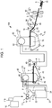
- FIG. 1 is a schematic view of the fiber assembly-forming apparatus 100.
- the fiber assembly-forming apparatus 100 includes, for example, a supply section 10, a rough crushing section 12, a disintegration section 20, a screening section 40, a first web-forming section 45, a rotator 49, a deposition section 60, a second web-forming section 70, a sheet-forming section 80, a cutting section 90, and a provision section 110.
- the supply section 10 supplies a feedstock to the rough crushing section 12.
- the supply section 10 is, for example, an automatic input section for continuously inputting the feedstock to the rough crushing section 12.
- the feedstock supplied by the supply section 10 contains, for example, fibers of waste paper, pulp sheets, or the like.
- the provision section 110 provides the feedstock supplied from the supply section 10 with a binding material bonding the fibers to each other. Details of the provision section 110 are described below.
- the rough crushing section 12 cuts the feedstock supplied by the supply section 10 into small pieces in gas such as air.
- the small pieces are, for example, several centimeters square pieces.
- the rough crushing section 12 includes rough crushing blades 14 and can cut the input feedstock with the rough crushing blades 14.
- the rough crushing section 12 used is, for example, a shredder.
- the feedstock cut by the rough crushing section 12 is received in a hopper 1 and is then transferred to the disintegration section 20 through a pipe 2.
- the disintegration section 20 disintegrates the feedstock cut by the rough crushing section 12.
- the term "disintegrate” as used herein means that a feedstock containing a plurality of bonded fibers is disentangled into the fibers one by one.
- the disintegration section 20 has the function of removing substances, such as resin particles, ink, toner, and a bleeding inhibitor, adhering to the feedstock from fibers.
- Disintegrated matter contains disentangled disintegrated fibers and also contains resin particles separated from fibers when the fibers are disintegrated, a colorant such as ink or toner, or an additive such as a bleeding inhibitor or a paper strength additive in some cases.
- Disentangled disintegrated matter is string-shaped.
- the disentangled disintegrated matter may be present in such a state that the disentangled disintegrated matter is not intertwined with other disentangled fibers, that is, such a state that the disentangled disintegrated matter is independent or in such a state that the disentangled disintegrated matter is intertwined with other disentangled fibers to form aggregates, that is, such a state that the disentangled disintegrated matter forms lumps.
- the disintegration section 20 performs disintegration in a dry mode.
- performing treatment such as disintegration in gas, such as air, rather than liquid is referred to as a dry mode.
- the disintegration section 20 used is, for example, an impeller mill.
- the disintegration section 20 has the function of generating such an air flow that sucks the feedstock and discharges the disintegrated matter. This enables the disintegration section 20 to suck the feedstock from an inlet 22 by means of an air flow generated by the disintegration section 20 together with the air flow, to disintegrate the feedstock, and to transport the disintegrated matter to an outlet 24.
- the disintegrated matter having passed through the disintegration section 20 is transferred to the screening section 40 through a pipe 3.
- an air flow for transporting the disintegrated matter from the disintegration section 20 to the screening section 40 may be the air flow generated by the disintegration section 20 or an air flow generated by an air flow generator such as a blower.
- the screening section 40 imports the disintegrated matter having passed through the disintegration section 20 from an inlet 42 and screens the disintegrated matter depending on the length of fibers.
- the screening section 40 includes a drum portion 41 and a housing portion 43 that houses the drum portion 41.
- the drum portion 41 used is, for example, a sieve.
- the drum portion 41 includes a net and can separate fibers or particles smaller than the size of openings of the net, that is, first screened fractions passing through the net, and fibers, undisintegrated pieces, or lumps larger than the size of the openings of the net, that is, second screened fractions not passing through the net.
- the first screened fractions are transferred to the deposition section 60 through a pipe 7.
- the second screened fractions are returned to the disintegration section 20 from an outlet 44 through a pipe 8.
- the drum portion 41 is a cylindrical sieve rotationally driven with a motor.
- the net of the drum portion 41 used is, for example, a metal gauze, an expanded metal obtained by expanding a slit metal plate, or a punching metal obtained by forming holes in a metal plate with a press or the like.
- the first web-forming section 45 transports the first screened fractions having passed through the screening section 40 to the pipe 7.
- the first web-forming section 45 includes a mesh belt 46, tension rollers 47, and a suction mechanism 48.
- the suction mechanism 48 can suck the first screened fractions which have passed through openings of the screening section 40 and which have been distributed in air onto the mesh belt 46.
- the first screened fractions are deposited on the moving mesh belt 46 to form a web V.
- the basic configuration of the mesh belt 46, the tension rollers 47, and the suction mechanism 48 is substantially the same as that of a mesh belt 72, tension rollers 74, and suction mechanism 76 of the second web-forming section 70 as described below.
- the web V passes through the screening section 40 and the first web-forming section 45 and is thereby formed in such a state that the web V contains a lot of air, is soft, and is bulgy.
- the web V deposited on the mesh belt 46 is input to the pipe 7 and is transported to the deposition section 60.
- the rotator 49 can cut the web V.
- the rotator 49 includes a base portion 49a and protruding portions 49b protruding from the base portion 49a.
- the protruding portions 49b have, for example, a plate shape.
- the number of the protruding portions 49b is four and the four protruding portions 49b are arranged at equal intervals.
- the base portion 49a rotates in a direction R and therefore the protruding portions 49b can rotate about the base portion 49a. Cutting the web V by the rotator 49 enables, for example, the change in amount of the disintegrated matter supplied to the deposition section 60 per unit time to be reduced.
- the rotator 49 is placed in the vicinity of the first web-forming section 45.
- the rotator 49 is placed in the vicinity of a tension roller 47a located downstream in the path of the web V.
- the rotator 49 is placed at a position where the protruding portions 49b can come into contact with the web V and do not come into contact with the mesh belt 46, on which the web V is deposited. This enables the mesh belt 46 to be inhibited from being worn by the protruding portions 49b.
- the shortest distance between each protruding portion 49b and the mesh belt 46 is, for example, 0.05 mm to 0.5 mm. This is the distance that the web V can be cut without damaging the mesh belt 46.
- the deposition section 60 imports the first screened fractions from an inlet 62, disentangles the intertwined disintegrated matter, and sprays the disentangled disintegrated matter such that the disentangled disintegrated matter is dispersed in air.
- the deposition section 60 can uniformly deposit the first screened fractions on the second web-forming section 70.
- the deposition section 60 includes a drum portion 61 and a housing portion 63 that houses the drum portion 61.
- the drum portion 61 used is, for example, a rotary cylindrical sieve.
- the drum portion 61 includes a net and sprays fibers or particles smaller than the size of openings of the net.
- the configuration of the drum portion 61 is the same as, for example, the configuration of the drum portion 41.
- the "sieve" of the drum portion 61 need not have the function of screening a specific target. That is, the "sieve” used as the drum portion 61 means one equipped with a net. The drum portion 61 may spray all of the disintegrated matter imported into the drum portion 61.
- the second web-forming section 70 deposits a passing object having passed through the deposition section 60 to form a web W.
- the second web-forming section 70 includes, for example, a mesh belt 72, tension rollers 74, and a suction mechanism 76.
- the mesh belt 72 allows the passing object having passed through an opening of the deposition section 60 to be deposited thereon while moving.
- the mesh belt 72 is tensioned by the tension rollers 74 and is configured such that the passing object is unlikely to pass through the mesh belt 72 and air passes through the mesh belt 72.
- the mesh belt 72 moves because the tension rollers 74 rotate.
- the passing object having passed through the deposition section 60 is deposited on the mesh belt 72 that is continuously moving, whereby the web W is formed on the mesh belt 72.
- the suction mechanism 76 is placed under the mesh belt 72.
- the suction mechanism 76 can generate an air flow directed downward.
- the disintegrated matter dispersed in air by the deposition section 60 can be sucked onto the mesh belt 72 by the suction mechanism 76. This enables the discharge rate from the deposition section 60 to be increased.
- a down-flow can be formed in the fall path of the disintegrated matter by the suction mechanism 76, thereby enabling the disintegrated matter and an additive to be prevented from being intertwined during falling.
- passing through the deposition section 60 and the second web-forming section 70 allows the web W to be formed in such a state that the web W contains a lot of air, is soft, and is bulgy.
- the web W deposited on the mesh belt 72 is transported to the sheet-forming section 80.
- the sheet-forming section 80 pressurizes and heats the web W deposited on the mesh belt 72 to form a sheet S. In the sheet-forming section 80, heat is applied to a mixture of the disintegrated matter and binding material mixed together in the web W, thereby enabling a plurality of fibers in the mixture to be bonded to each other with the binding material.
- the sheet-forming section 80 includes a pressurizing portion 82 pressurizing the web W and a heating portion 84 heating the web W pressurized by the pressurizing portion 82.
- the pressurizing portion 82 is composed of a pair of calender rollers 85 and applies a pressure to the web W. Pressurizing the web W reduces the thickness of the web W and increases the bulk density of the web W.
- the heating portion 84 used is, for example, a heating roller, a hot press molding machine, a hotplate, a hot air blower, an infrared heater, or a flash-fusing system. In the illustrated example, the heating portion 84 includes a pair of heating rollers 86.
- the calender rollers 85 and the heating rollers 86 are arranged such that, for example, the axes of rotation thereof are parallel.
- the calender rollers 85 can apply a higher pressure to the web W than the pressure applied to the web W by the heating rollers 86.
- the number of the calender rollers 85 and the heating rollers 86 is not particularly limited.
- the cutting section 90 cuts the sheet S formed by the sheet-forming section 80.
- the cutting section 90 includes a first cutting portion 92 cutting the sheet S in a direction crossing the transport direction of the sheet S and a second cutting portion 94 cutting the sheet S in a direction parallel to the transport direction thereof.
- the second cutting portion 94 cuts the sheet S having passed through, for example, the first cutting portion 92.
- the above allows the sheet S to be formed such that the sheet S is a single sheet with a predetermined size.
- the cut sheet S which is such a single sheet, is discharged to a discharge section 96.
- the provision section 110 provides the feedstock, which contains the fibers, with the binding material, which bonds the fibers to each other.
- the feedstock, which contains the fibers is, for example, waste paper.
- the provision section 110 provides the feedstock which is supplied from the supply section 10 and which is roughly uncrushed by the rough crushing section 12 with the binding material.
- the length of the fibers contained in the feedstock is, for example, 0.6 mm to 3.0 mm as length-weighted mean length.
- the length-weighted mean length of the fibers can be measured in accordance with ISO 16065-2:2007 using L&W Fiber Tester CODE 912.
- the provision section 110 may apply liquid containing the binding material to a surface of the feedstock.
- the provision section 110 may include a roller applying the binding material to the feedstock.
- the provision section 110 may include a spray discharging the binding material to the feedstock.
- the provision section 110 may be an ink jet head discharging the binding material to the feedstock.
- the binding material which is provided from the provision section 110, may be dissolved or dispersed in liquid.
- the liquid is preferably emulsion in which the binding material is dispersed.
- the binding material is preferably nano-sized.
- the viscosity of the liquid can be reduced, the liquid can penetrate to the inside of a fiber assembly, and the bonding force can be further enhanced, which is preferable.
- the binding material is nano-sized, for example, nozzle clogging, which occurs in sprays and ink jet heads, is likely to be avoided, which is preferable.
- the binding material which is provided from the provision section 110, is, for example, a thermoplastic resin or a thermosetting resin.
- thermoplastic resin examples include an acrylonitrile-styrene (AS) resin, an acrylonitrile-butadiene-styrene (ABS) resin, polypropylene, polyethylene, polyvinyl chloride, polystyrene, an acrylic resin, a polyester resin, polyethylene terephthalate, polyphenylene ether, polybutylene terephthalate, nylon, polyamide, polycarbonate, polyacetal, polyphenylene sulfide, and polyether ether ketone. These resins may be used alone or in combination and may be copolymerized or modified.
- AS acrylonitrile-styrene
- ABS acrylonitrile-butadiene-styrene
- acrylic resin a polyester resin
- polyethylene terephthalate polyphenylene ether
- polybutylene terephthalate nylon
- polyamide polycarbonate
- polyacetal polyphenylene sulfide
- polyether ether ketone examples
- Examples of a family of these resins include styrenic resins, acrylic resins, styrene-acrylic copolymers, olefinic resins, vinyl chloride resins, polyester resins, polyamide resins, polyurethane resins, polyvinyl alcohol resins, vinyl ether resins, N-vinyl resins, and styrene-butadiene resins.
- thermosetting resin examples include a phenol resin, an epoxy resin, a melamine resin, a urea resin, an unsaturated polyester resin, an alkyd resin, polyurethane, and a thermosetting polyimide resin.
- the glass transition temperature of the thermoplastic resin and the thermosetting resin is preferably high from the viewpoint of high-temperature resistance and is in an appropriate range in consideration of reasons such as energy saving in terms of manufacture.
- the glass transition temperature is appropriately selected depending on, for example, the thickness or heat treatment temperature of the sheet S.
- the glass transition temperature is preferably 45 °C or higher, more preferably 50 °C or higher, and further more preferably 60 °C or higher.
- the glass transition temperature is preferably 130 °C or less and more preferably 100 °C or lower.
- the binding material is softened by the heat of the disintegration section 20 to adhere to the disintegration section 20 in the course of disintegrating the feedstock provided with the binding material in the disintegration section 20.
- the binding material is preferably resin having a melting point higher than or equal to the temperature of the disintegration section 20.
- the melting point of the binding material is preferably 220 °C or lower.
- the provision section 110 provides the feedstock with the binding material such that the binding material accounts for 6.0% by mass or more of the fibers contained in the feedstock, preferably 9.0% by mass or more.
- the binding material accounts for 6.0% by mass or more of the fibers
- the paper strength of the sheet S can be enhanced.
- the sheet S contains the binding material such that the binding material accounts for, for example, 6.0% by mass or more of the fibers.
- the provision section 110 may provide the feedstock with an additive such as a flame retardant, a perfume, an antistatic agent, or an ultraviolet absorber in addition to the binding material. If the additive is provided from the provision section 110 together with the binding material, a cartridge for providing the additive need not be used. Therefore, the downsizing of an apparatus is possible. The provision section 110 does not provide the feedstock with any colorant.
- an additive such as a flame retardant, a perfume, an antistatic agent, or an ultraviolet absorber
- the provision section 110 may provide the feedstock roughly crushed by the rough crushing section 12 with the binding material. This is not shown.
- the provision section 110 is preferably a spray.
- the provision section 110 preferably provides the feedstock roughly uncrushed by the rough crushing section 12 with the binding material.
- the provision section 110 may provide the binding material to the feedstock in the form of powder instead of the liquid containing the binding material.
- the binding material is powder
- the binding material is preferably fixed to the feedstock by heat for the purpose of suppressing the fall of the binding material from the feedstock.
- the binding material may be charged into the disintegration section 20 such that the binding material is fixed to the feedstock by the heat of the disintegration section 20.
- the fiber assembly-forming apparatus 100 has, for example, effects below.
- the fiber assembly-forming apparatus 100 includes, the provision section 110, which provides the feedstock containing the fibers with the binding material bonding the fibers to each other; the disintegration section 20, which disintegrates the feedstock provided with the binding material to form the disintegrated matter; the deposition section 60, which deposits the disintegrated matter; and the heating portion 84, which heat the deposited disintegrated matter. Therefore, in the fiber assembly-forming apparatus 100, the binding material need not be provided to the disintegrated matter deposited by the deposition section 60 and therefore there is no possibility that the fibers rise from the mesh belt 46 in the form of paper dust to clog a nozzle of the provision section 110. Thus, the sheet S (fiber assembly) can be formed so as to have little variation in paper strength.
- the disintegration section 20 has the function of mixing the feedstock and the binding material together. Therefore, even if the binding material is unevenly distributed at the point in time when the binding material is provided to the feedstock, the uneven distribution of the binding material can be reduced by the disintegration section 20 and the sheet S can be formed so as to have little variation in paper strength. Thus, if the nozzle of the provision section 110 is partly clogged, the binding material can be provided without regard to the unevenness of the binding material. Furthermore, since a mixing section mixing the feedstock and the binding material together is not necessary, the downsizing of an apparatus is possible.
- the provision section 110 may include a roller applying the binding material to the feedstock. Therefore, in the fiber assembly-forming apparatus 100, the binding material can be uniformly applied to the feedstock.
- the roller can readily apply the binding material to the feedstock without consideration of the viscosity of the liquid containing the binding material as compared to sprays and ink jet heads.
- the binding material may be the thermoplastic resin or the thermosetting resin and the glass transition temperature of the binding material may be 45 °C or higher. Therefore, in the fiber assembly-forming apparatus 100, the binding material can be readily melted by the heating portion 84.
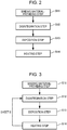
- FIG. 2 is a flowchart illustrating the fiber assembly-forming method.
- the fiber assembly-forming method is performed using, for example, the above-mentioned fiber assembly-forming apparatus 100.
- the fiber assembly-forming method may be performed using an apparatus other than the fiber assembly-forming apparatus 100.
- the fiber assembly-forming method includes a binding material-providing step (Step S11) of providing a feedstock containing fibers with a binding material bonding the fibers to each other, a disintegration step (Step S12) of forming disintegrated matter by disintegrating the feedstock provided with the binding material, a deposition step (Step S13) of depositing the disintegrated matter, and a heating step (Step S14) of heating the deposited disintegrated matter.
- the binding material-providing step (Step S11) is performed using, for example, the provision section 110 of the fiber assembly-forming apparatus 100.
- the disintegration step (Step S12) is performed using, for example, the disintegration section 20 of the fiber assembly-forming apparatus 100.
- the deposition step (Step S13) is performed using, for example, the deposition section 60 of the fiber assembly-forming apparatus 100.
- the heating step (Step S14) is performed using, for example, the heating portion 84 of the fiber assembly-forming apparatus 100.
- the fiber assembly-forming method may include, for example, a step such as a step of pressurizing the web W by the pressurizing portion 82 as described in above-mentioned "1. Fiber Assembly-Forming Apparatus" in addition to the above steps.
- the sheet S can be formed so as to have little variation in paper strength as described in above-mentioned "1. Fiber Assembly-Forming Apparatus”.
- the feedstock provided with the binding material in the binding material-providing step is disintegrated.
- the feedstock (first feedstock) provided with the binding material in the binding material-providing step and the sheet S formed through the heating step may be disintegrated.
- the sheet S is a feedstock (second feedstock) unprovided with the binding material.
- the disintegration section 20 may disintegrate the first feedstock and the second feedstock.
- feedstock unprovided with the binding material refers to material that is a sheet, formed through the heating step, unprovided with the binding material in the binding material-providing step.
- the feedstock provided with the binding material in the binding material-providing step and the sheet S, formed through the binding material-providing step, provided with the binding material in the binding material-providing step may be disintegrated.
- FIG. 5 is a flowchart illustrating the modification.
- the modification what is different from the fiber assembly-forming method is described and what is common to the fiber assembly-forming method is not described.
- the fiber assembly-forming method includes the binding material-providing step (Step S11).
- the modification includes a material-preparing step (Step S21) of preparing material containing fibers and a binding material boding the fibers to each other.
- the modification includes the material-preparing step (Step S21), a disintegration step (Step S22) of forming disintegrated matter by disintegrating the material, a deposition step (Step S23) of depositing the disintegrated matter, and a heating step (Step S24) of heating the deposited disintegrated matter.
- the material contains, for example, waste paper and a resinous substance made of the binding material.
- the resinous substance may be composed of a thermoplastic resin or a thermosetting resin or may be composed of the thermoplastic resin and the thermosetting resin.
- the shape of the resinous substance is not particularly limited and is, for example, a sheet shape (single sheet shape), a strip shape formed by fragmenting a single sheet, a dice shape, or a spherical shape.
- the resinous substance is preferably a sheet-shaped resin sheet.
- the resinous substance can be supplied by attaching a sheet-feeding stacker for supplying the resinous substance to the supply section 10 of the fiber assembly-forming apparatus 100.
- the material-preparing step the same number of resin sheets as that of sheets of waste paper may be prepared.
- the provision section 110 need not be driven. Alternatively, the provision section 110 need not be used.
- the material is prepared such that the binding material accounts for 6.0% by mass or more of the fibers.
- the material is preferably prepared such that the binding material accounts for 9.0% by mass or more of the fibers.
- the disintegration step (Step S22) is substantially the same as the above-mentioned disintegration step (Step S12).
- the deposition step (Step S23) is substantially the same as the above-mentioned deposition step (Step S13).
- the heating step (Step S24) is substantially the same as the above-mentioned heating step (Step S14).
- the modification has, for example, effects below.
- the sheet S can be formed so as to variation in paper strength.
- the material in the material-preparing step, may contain a resinous substance made of the binding material. Therefore, liquid containing the binding material need not be applied; hence, a drying step subsequent to the application of the liquid can be omitted.
- a sheet-shaped resinous substance is easy in stock control and has good operation efficiency. Furthermore, the type of the resinous substance can be selected without being restricted by crushability, powder characteristics such as fluidity, dispersibility, dischargeability, storage stability, or compatibility.
- a plurality of different functional agents can be provided to the fibers depending on purposes using a resinous substance made of resins with different glass transition temperatures or a resinous substance containing a flame retardant, an antistatic agent, an ultraviolet absorber, a perfume, and the like; hence, functional customization is easy.
- the sheet S which is formed through the heating step, may be prepared as material in addition to the waste paper and the resinous substance as shown in FIG. 6 .
- the waste paper and the sheet S may be prepared as material without preparing the resinous substance.
- Liquid was provided to recycled paper, G80 (a basis weight of 64 g/m 2 ), available from Mitsubishi Paper Mills, Ltd. using an ink jet printer, EW-M770T, available from Seiko Epson Corporation, whereby a feedstock was prepared.
- Components of the liquid were as described below. Table 1 Components of liquid Mass percent Polyurethane 15 PG 10 E1010 1 Water Balance Total 100
- Polyurethane used was SUPERFLEX 130 available from Dai-ichi Kogyo Seiyaku Co., Ltd. Polyurethane is a binding material bonding fibers to each other.
- Table 1 "PG” is polypropylene glycol and "E1010” is Olfine E1010 available from Nissin Chemical Industry Co., Ltd.
- a sheet with a basis weight of 70 g/m 2 was prepared using a papermaking machine, PaperLab A8000, available from Seiko Epson Corporation and the feedstock coated with the liquid.
- the content of the binding material with respect to fibers in the sheet was 9.0% by mass.
- PaperLab A8000 no binding material was provided to the feedstock. That is, in Example 1, after liquid containing the binding material was applied, disintegration was performed.
- a web was prepared using G80 as a feedstock without providing the binding material in PaperLab A8000.
- the liquid shown in FIG. 1 was applied to the web using EW-M770T. Thereafter, the web was pressurized with a pressurizing portion and was heated with a heating portion, whereby a sheet with a basis weight of 70 g/m 2 was prepared. That is, in Comparative Example 1, after disintegration was performed, liquid containing the binding material was applied.
- Example 1 since disintegration was performed after printing, the prepared sheet had no dropouts due to dot loss. Therefore, Example 1 showed a specific tensile strength higher than that in Comparative Example 1. Furthermore, in Example 1, since disintegration was performed after printing, the binding material was homogenized and no uneven application was observed, even though printing was repeatedly performed in such a state that the four nozzles were clogged. These evaluations showed that a sheet with little variation in paper strength could be formed by applying liquid containing the binding material before performing disintegration.
- the present disclosure is not limited to the above embodiments and various modifications can be made.
- the present disclosure includes, for example, substantially the same configurations as configurations described in the embodiments.
- Substantially the same configurations are, for example, configurations identical in function, method, and result or configurations identical in object and effect.
- the present disclosure includes configurations obtained by replacing nonessential portions of configurations described in the embodiments.
- the present disclosure includes configurations capable of providing the same advantageous effects as those of configurations described in the embodiments or capable of achieving the same object.
- the present disclosure includes configurations obtained by adding a known technique to configurations described in the embodiments.
Landscapes
- Engineering & Computer Science (AREA)
- Textile Engineering (AREA)
- Chemical & Material Sciences (AREA)
- Chemical Kinetics & Catalysis (AREA)
- Life Sciences & Earth Sciences (AREA)
- Wood Science & Technology (AREA)
- Mechanical Engineering (AREA)
- Manufacturing & Machinery (AREA)
- Nonwoven Fabrics (AREA)
- Dry Formation Of Fiberboard And The Like (AREA)
- Paper (AREA)
Abstract
Description
- The present application is based on, and claims priority from
JP Application Serial Number 2019-216462, filed November 29, 2019 - The present disclosure relates to a fiber assembly-forming method, a fiber assembly-forming apparatus, and a sheet.
- Dry fiber assembly-forming apparatuses using substantially no water for the purpose of size reduction and energy saving have been proposed. For example,
JP-A-2012-144826 - However, in the manner described in
JP-A-2012-144826 - According to an aspect of the present disclosure, a fiber assembly-forming method includes a step of providing a first feedstock containing fibers with a binding material bonding the fibers to each other, a step of forming disintegrated matter by disintegrating the first feedstock provided with the binding material, a step of depositing the disintegrated matter, and a step of heating the deposited disintegrated matter.
- In the fiber assembly-forming method, in the step of providing the binding material, the binding material may be applied to a surface of the first feedstock.
- In the fiber assembly-forming method, in the step of forming the disintegrated matter, the first feedstock provided with the binding material and a second feedstock unprovided with the binding material may be disintegrated.
- According to an aspect of the present disclosure, a fiber assembly-forming method includes a step of preparing material containing fibers and a binding material bonding the fibers to each other, a step of forming disintegrated matter by disintegrating the material, a step of depositing the disintegrated matter, and a step of heating the deposited disintegrated matter. In the step of preparing the material, the material is prepared such that the binding material accounts for 6.0% by mass or more of the fibers.
- In the fiber assembly-forming method, in the step of preparing the material, the material may contain a resinous substance made of the binding material.
- In the fiber assembly-forming method, the binding material may be a thermoplastic resin or a thermosetting resin and the glass transition temperature of the binding material may be 45 °C or higher.
- According to an aspect of the present disclosure, a fiber assembly-forming apparatus includes a provision section providing a first feedstock containing fibers with a binding material bonding the fibers to each other, a disintegration section disintegrating the first feedstock provided with the binding material to form disintegrated matter, a deposition section depositing the disintegrated matter, and a heating portion heating the deposited disintegrated matter.
- In the fiber assembly-forming apparatus, the provision section may include a roller applying the binding material to the first feedstock.
- In the fiber assembly-forming apparatus, the provision section may include a spray discharging the binding material to the first feedstock.
- In the fiber assembly-forming apparatus, the disintegration section may disintegrate the first feedstock provided with the binding material and a second feedstock unprovided with the binding material.
- In the fiber assembly-forming apparatus, the binding material may be a thermoplastic resin or a thermosetting resin and the glass transition temperature of the binding material may be 45 °C or higher.
- According to an aspect of the present disclosure, a sheet contains fibers and resin. The resin may be contained so as to account for 6.0% by mass or more of the fibers.
-
-
FIG. 1 is a schematic view of a fiber assembly-forming apparatus according to an embodiment of the present disclosure. -
FIG. 2 is a flowchart illustrating a fiber assembly-forming method according to an embodiment of the present disclosure. -
FIG. 3 is a flowchart illustrating the fiber assembly-forming method. -
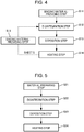
FIG. 4 is a flowchart illustrating the fiber assembly-forming method. -
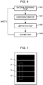
FIG. 5 is a flowchart illustrating a modification of the fiber assembly-forming method. -
FIG. 6 is a flowchart illustrating the modification of the fiber assembly-forming method. -
FIG. 7 is an illustration of a sheet used for evaluation. - Preferred embodiments of the present disclosure will now be described in detail with reference to the accompanying drawings. The embodiments below do not unfairly limit the scope of the present disclosure that is recited in the claims. All of components described below are not necessarily essential elements of the present disclosure.
- A fiber assembly-forming
apparatus 100 according to an embodiment of the present disclosure is described with reference to a drawing.FIG. 1 is a schematic view of the fiber assembly-formingapparatus 100. - As shown in
FIG. 1 , the fiber assembly-formingapparatus 100 includes, for example, asupply section 10, a rough crushing section 12, adisintegration section 20, ascreening section 40, a first web-formingsection 45, arotator 49, adeposition section 60, a second web-formingsection 70, a sheet-formingsection 80, acutting section 90, and aprovision section 110. - The
supply section 10 supplies a feedstock to the rough crushing section 12. Thesupply section 10 is, for example, an automatic input section for continuously inputting the feedstock to the rough crushing section 12. The feedstock supplied by thesupply section 10 contains, for example, fibers of waste paper, pulp sheets, or the like. - The
provision section 110 provides the feedstock supplied from thesupply section 10 with a binding material bonding the fibers to each other. Details of theprovision section 110 are described below. - The rough crushing section 12 cuts the feedstock supplied by the
supply section 10 into small pieces in gas such as air. The small pieces are, for example, several centimeters square pieces. In an illustrated example, the rough crushing section 12 includes rough crushingblades 14 and can cut the input feedstock with the rough crushingblades 14. The rough crushing section 12 used is, for example, a shredder. The feedstock cut by the rough crushing section 12 is received in ahopper 1 and is then transferred to thedisintegration section 20 through apipe 2. - The
disintegration section 20 disintegrates the feedstock cut by the rough crushing section 12. The term "disintegrate" as used herein means that a feedstock containing a plurality of bonded fibers is disentangled into the fibers one by one. Thedisintegration section 20 has the function of removing substances, such as resin particles, ink, toner, and a bleeding inhibitor, adhering to the feedstock from fibers. - One having passed through the
disintegration section 20 is referred to as "disintegrated matter". The "disintegrated matter" contains disentangled disintegrated fibers and also contains resin particles separated from fibers when the fibers are disintegrated, a colorant such as ink or toner, or an additive such as a bleeding inhibitor or a paper strength additive in some cases. Disentangled disintegrated matter is string-shaped. The disentangled disintegrated matter may be present in such a state that the disentangled disintegrated matter is not intertwined with other disentangled fibers, that is, such a state that the disentangled disintegrated matter is independent or in such a state that the disentangled disintegrated matter is intertwined with other disentangled fibers to form aggregates, that is, such a state that the disentangled disintegrated matter forms lumps. - The
disintegration section 20 performs disintegration in a dry mode. Herein, performing treatment such as disintegration in gas, such as air, rather than liquid is referred to as a dry mode. Thedisintegration section 20 used is, for example, an impeller mill. Thedisintegration section 20 has the function of generating such an air flow that sucks the feedstock and discharges the disintegrated matter. This enables thedisintegration section 20 to suck the feedstock from aninlet 22 by means of an air flow generated by thedisintegration section 20 together with the air flow, to disintegrate the feedstock, and to transport the disintegrated matter to anoutlet 24. The disintegrated matter having passed through thedisintegration section 20 is transferred to thescreening section 40 through apipe 3. Incidentally, an air flow for transporting the disintegrated matter from thedisintegration section 20 to thescreening section 40 may be the air flow generated by thedisintegration section 20 or an air flow generated by an air flow generator such as a blower. - The
screening section 40 imports the disintegrated matter having passed through thedisintegration section 20 from aninlet 42 and screens the disintegrated matter depending on the length of fibers. Thescreening section 40 includes adrum portion 41 and ahousing portion 43 that houses thedrum portion 41. Thedrum portion 41 used is, for example, a sieve. Thedrum portion 41 includes a net and can separate fibers or particles smaller than the size of openings of the net, that is, first screened fractions passing through the net, and fibers, undisintegrated pieces, or lumps larger than the size of the openings of the net, that is, second screened fractions not passing through the net. For example, the first screened fractions are transferred to thedeposition section 60 through a pipe 7. The second screened fractions are returned to thedisintegration section 20 from anoutlet 44 through apipe 8. In particular, thedrum portion 41 is a cylindrical sieve rotationally driven with a motor. The net of thedrum portion 41 used is, for example, a metal gauze, an expanded metal obtained by expanding a slit metal plate, or a punching metal obtained by forming holes in a metal plate with a press or the like. - The first web-forming
section 45 transports the first screened fractions having passed through thescreening section 40 to the pipe 7. The first web-formingsection 45 includes amesh belt 46,tension rollers 47, and asuction mechanism 48. - The
suction mechanism 48 can suck the first screened fractions which have passed through openings of thescreening section 40 and which have been distributed in air onto themesh belt 46. The first screened fractions are deposited on the movingmesh belt 46 to form a web V. The basic configuration of themesh belt 46, thetension rollers 47, and thesuction mechanism 48 is substantially the same as that of amesh belt 72,tension rollers 74, andsuction mechanism 76 of the second web-formingsection 70 as described below. - The web V passes through the
screening section 40 and the first web-formingsection 45 and is thereby formed in such a state that the web V contains a lot of air, is soft, and is bulgy. The web V deposited on themesh belt 46 is input to the pipe 7 and is transported to thedeposition section 60. - The
rotator 49 can cut the web V. In the illustrated example, therotator 49 includes abase portion 49a and protrudingportions 49b protruding from thebase portion 49a. The protrudingportions 49b have, for example, a plate shape. In the illustrated example, the number of the protrudingportions 49b is four and the four protrudingportions 49b are arranged at equal intervals. Thebase portion 49a rotates in a direction R and therefore the protrudingportions 49b can rotate about thebase portion 49a. Cutting the web V by therotator 49 enables, for example, the change in amount of the disintegrated matter supplied to thedeposition section 60 per unit time to be reduced. - The
rotator 49 is placed in the vicinity of the first web-formingsection 45. In the illustrated example, therotator 49 is placed in the vicinity of atension roller 47a located downstream in the path of the web V. Therotator 49 is placed at a position where the protrudingportions 49b can come into contact with the web V and do not come into contact with themesh belt 46, on which the web V is deposited. This enables themesh belt 46 to be inhibited from being worn by the protrudingportions 49b. The shortest distance between each protrudingportion 49b and themesh belt 46 is, for example, 0.05 mm to 0.5 mm. This is the distance that the web V can be cut without damaging themesh belt 46. - The
deposition section 60 imports the first screened fractions from aninlet 62, disentangles the intertwined disintegrated matter, and sprays the disentangled disintegrated matter such that the disentangled disintegrated matter is dispersed in air. Thedeposition section 60 can uniformly deposit the first screened fractions on the second web-formingsection 70. - The
deposition section 60 includes adrum portion 61 and ahousing portion 63 that houses thedrum portion 61. Thedrum portion 61 used is, for example, a rotary cylindrical sieve. Thedrum portion 61 includes a net and sprays fibers or particles smaller than the size of openings of the net. The configuration of thedrum portion 61 is the same as, for example, the configuration of thedrum portion 41. - Incidentally, the "sieve" of the
drum portion 61 need not have the function of screening a specific target. That is, the "sieve" used as thedrum portion 61 means one equipped with a net. Thedrum portion 61 may spray all of the disintegrated matter imported into thedrum portion 61. - The second web-forming
section 70 deposits a passing object having passed through thedeposition section 60 to form a web W. The second web-formingsection 70 includes, for example, amesh belt 72,tension rollers 74, and asuction mechanism 76. - The
mesh belt 72 allows the passing object having passed through an opening of thedeposition section 60 to be deposited thereon while moving. Themesh belt 72 is tensioned by thetension rollers 74 and is configured such that the passing object is unlikely to pass through themesh belt 72 and air passes through themesh belt 72. Themesh belt 72 moves because thetension rollers 74 rotate. The passing object having passed through thedeposition section 60 is deposited on themesh belt 72 that is continuously moving, whereby the web W is formed on themesh belt 72. - The
suction mechanism 76 is placed under themesh belt 72. Thesuction mechanism 76 can generate an air flow directed downward. The disintegrated matter dispersed in air by thedeposition section 60 can be sucked onto themesh belt 72 by thesuction mechanism 76. This enables the discharge rate from thedeposition section 60 to be increased. Furthermore, a down-flow can be formed in the fall path of the disintegrated matter by thesuction mechanism 76, thereby enabling the disintegrated matter and an additive to be prevented from being intertwined during falling. - As described above, passing through the
deposition section 60 and the second web-formingsection 70 allows the web W to be formed in such a state that the web W contains a lot of air, is soft, and is bulgy. The web W deposited on themesh belt 72 is transported to the sheet-formingsection 80. - The sheet-forming
section 80 pressurizes and heats the web W deposited on themesh belt 72 to form a sheet S. In the sheet-formingsection 80, heat is applied to a mixture of the disintegrated matter and binding material mixed together in the web W, thereby enabling a plurality of fibers in the mixture to be bonded to each other with the binding material. - The sheet-forming
section 80 includes a pressurizingportion 82 pressurizing the web W and aheating portion 84 heating the web W pressurized by the pressurizingportion 82. The pressurizingportion 82 is composed of a pair ofcalender rollers 85 and applies a pressure to the web W. Pressurizing the web W reduces the thickness of the web W and increases the bulk density of the web W. Theheating portion 84 used is, for example, a heating roller, a hot press molding machine, a hotplate, a hot air blower, an infrared heater, or a flash-fusing system. In the illustrated example, theheating portion 84 includes a pair ofheating rollers 86. Composing theheating portion 84 using theheating rollers 86, rather than composing theheating portion 84 as a plate-like press machine, enables the sheet S to be formed in such a manner that the web W is continuously transported. Thecalender rollers 85 and theheating rollers 86 are arranged such that, for example, the axes of rotation thereof are parallel. Thecalender rollers 85 can apply a higher pressure to the web W than the pressure applied to the web W by theheating rollers 86. The number of thecalender rollers 85 and theheating rollers 86 is not particularly limited. - The cutting
section 90 cuts the sheet S formed by the sheet-formingsection 80. In the illustrated example, the cuttingsection 90 includes afirst cutting portion 92 cutting the sheet S in a direction crossing the transport direction of the sheet S and asecond cutting portion 94 cutting the sheet S in a direction parallel to the transport direction thereof. Thesecond cutting portion 94 cuts the sheet S having passed through, for example, thefirst cutting portion 92. - The above allows the sheet S to be formed such that the sheet S is a single sheet with a predetermined size. The cut sheet S, which is such a single sheet, is discharged to a
discharge section 96. - The
provision section 110 provides the feedstock, which contains the fibers, with the binding material, which bonds the fibers to each other. The feedstock, which contains the fibers, is, for example, waste paper. In the illustrated example, theprovision section 110 provides the feedstock which is supplied from thesupply section 10 and which is roughly uncrushed by the rough crushing section 12 with the binding material. The length of the fibers contained in the feedstock is, for example, 0.6 mm to 3.0 mm as length-weighted mean length. The length-weighted mean length of the fibers can be measured in accordance with ISO 16065-2:2007 using L&W Fiber Tester CODE 912. - The
provision section 110 may apply liquid containing the binding material to a surface of the feedstock. Theprovision section 110 may include a roller applying the binding material to the feedstock. Alternatively, theprovision section 110 may include a spray discharging the binding material to the feedstock. Alternatively, theprovision section 110 may be an ink jet head discharging the binding material to the feedstock. - The binding material, which is provided from the
provision section 110, may be dissolved or dispersed in liquid. The liquid is preferably emulsion in which the binding material is dispersed. The binding material is preferably nano-sized. When the liquid is the emulsion, the viscosity of the liquid can be reduced, the liquid can penetrate to the inside of a fiber assembly, and the bonding force can be further enhanced, which is preferable. When the binding material is nano-sized, for example, nozzle clogging, which occurs in sprays and ink jet heads, is likely to be avoided, which is preferable. - The binding material, which is provided from the
provision section 110, is, for example, a thermoplastic resin or a thermosetting resin. - Examples of the thermoplastic resin include an acrylonitrile-styrene (AS) resin, an acrylonitrile-butadiene-styrene (ABS) resin, polypropylene, polyethylene, polyvinyl chloride, polystyrene, an acrylic resin, a polyester resin, polyethylene terephthalate, polyphenylene ether, polybutylene terephthalate, nylon, polyamide, polycarbonate, polyacetal, polyphenylene sulfide, and polyether ether ketone. These resins may be used alone or in combination and may be copolymerized or modified. Examples of a family of these resins include styrenic resins, acrylic resins, styrene-acrylic copolymers, olefinic resins, vinyl chloride resins, polyester resins, polyamide resins, polyurethane resins, polyvinyl alcohol resins, vinyl ether resins, N-vinyl resins, and styrene-butadiene resins.
- Examples of the thermosetting resin include a phenol resin, an epoxy resin, a melamine resin, a urea resin, an unsaturated polyester resin, an alkyd resin, polyurethane, and a thermosetting polyimide resin.
- The glass transition temperature of the thermoplastic resin and the thermosetting resin is preferably high from the viewpoint of high-temperature resistance and is in an appropriate range in consideration of reasons such as energy saving in terms of manufacture. The glass transition temperature is appropriately selected depending on, for example, the thickness or heat treatment temperature of the sheet S. The glass transition temperature is preferably 45 °C or higher, more preferably 50 °C or higher, and further more preferably 60 °C or higher. The glass transition temperature is preferably 130 °C or less and more preferably 100 °C or lower. When the glass transition temperature is 45 °C or higher, the softening of the binding material at high temperature is suppressed and the obtained sheet S has high paper strength. Furthermore, when the glass transition temperature is 60 °C or higher, it can be suppressed that the binding material is softened by the heat of the
disintegration section 20 to adhere to thedisintegration section 20 in the course of disintegrating the feedstock provided with the binding material in thedisintegration section 20. The binding material is preferably resin having a melting point higher than or equal to the temperature of thedisintegration section 20. The melting point of the binding material is preferably 220 °C or lower. - The
provision section 110 provides the feedstock with the binding material such that the binding material accounts for 6.0% by mass or more of the fibers contained in the feedstock, preferably 9.0% by mass or more. When the binding material accounts for 6.0% by mass or more of the fibers, the paper strength of the sheet S can be enhanced. The sheet S contains the binding material such that the binding material accounts for, for example, 6.0% by mass or more of the fibers. - The
provision section 110 may provide the feedstock with an additive such as a flame retardant, a perfume, an antistatic agent, or an ultraviolet absorber in addition to the binding material. If the additive is provided from theprovision section 110 together with the binding material, a cartridge for providing the additive need not be used. Therefore, the downsizing of an apparatus is possible. Theprovision section 110 does not provide the feedstock with any colorant. - When the feedstock is undisintegrated by the
disintegration section 20, theprovision section 110 may provide the feedstock roughly crushed by the rough crushing section 12 with the binding material. This is not shown. In this case, theprovision section 110 is preferably a spray. In a case where the binding material is applied to the feedstock using a roller, theprovision section 110 preferably provides the feedstock roughly uncrushed by the rough crushing section 12 with the binding material. - The
provision section 110 may provide the binding material to the feedstock in the form of powder instead of the liquid containing the binding material. However, when the binding material is powder, the binding material is preferably fixed to the feedstock by heat for the purpose of suppressing the fall of the binding material from the feedstock. For example, the binding material may be charged into thedisintegration section 20 such that the binding material is fixed to the feedstock by the heat of thedisintegration section 20. - The fiber assembly-forming
apparatus 100 has, for example, effects below. - The fiber assembly-forming
apparatus 100 includes, theprovision section 110, which provides the feedstock containing the fibers with the binding material bonding the fibers to each other; thedisintegration section 20, which disintegrates the feedstock provided with the binding material to form the disintegrated matter; thedeposition section 60, which deposits the disintegrated matter; and theheating portion 84, which heat the deposited disintegrated matter. Therefore, in the fiber assembly-formingapparatus 100, the binding material need not be provided to the disintegrated matter deposited by thedeposition section 60 and therefore there is no possibility that the fibers rise from themesh belt 46 in the form of paper dust to clog a nozzle of theprovision section 110. Thus, the sheet S (fiber assembly) can be formed so as to have little variation in paper strength. - Furthermore, in the fiber assembly-forming
apparatus 100, thedisintegration section 20 has the function of mixing the feedstock and the binding material together. Therefore, even if the binding material is unevenly distributed at the point in time when the binding material is provided to the feedstock, the uneven distribution of the binding material can be reduced by thedisintegration section 20 and the sheet S can be formed so as to have little variation in paper strength. Thus, if the nozzle of theprovision section 110 is partly clogged, the binding material can be provided without regard to the unevenness of the binding material. Furthermore, since a mixing section mixing the feedstock and the binding material together is not necessary, the downsizing of an apparatus is possible. - In the fiber assembly-forming
apparatus 100, theprovision section 110 may include a roller applying the binding material to the feedstock. Therefore, in the fiber assembly-formingapparatus 100, the binding material can be uniformly applied to the feedstock. The roller can readily apply the binding material to the feedstock without consideration of the viscosity of the liquid containing the binding material as compared to sprays and ink jet heads. - In the fiber assembly-forming
apparatus 100, the binding material may be the thermoplastic resin or the thermosetting resin and the glass transition temperature of the binding material may be 45 °C or higher. Therefore, in the fiber assembly-formingapparatus 100, the binding material can be readily melted by theheating portion 84. - Next, a fiber assembly-forming method according to an embodiment of the present disclosure is described with reference to a drawing.
FIG. 2 is a flowchart illustrating the fiber assembly-forming method. - The fiber assembly-forming method is performed using, for example, the above-mentioned fiber assembly-forming
apparatus 100. The fiber assembly-forming method may be performed using an apparatus other than the fiber assembly-formingapparatus 100. - As shown in
FIG. 2 , the fiber assembly-forming method includes a binding material-providing step (Step S11) of providing a feedstock containing fibers with a binding material bonding the fibers to each other, a disintegration step (Step S12) of forming disintegrated matter by disintegrating the feedstock provided with the binding material, a deposition step (Step S13) of depositing the disintegrated matter, and a heating step (Step S14) of heating the deposited disintegrated matter. - The binding material-providing step (Step S11) is performed using, for example, the
provision section 110 of the fiber assembly-formingapparatus 100. - The disintegration step (Step S12) is performed using, for example, the
disintegration section 20 of the fiber assembly-formingapparatus 100. - The deposition step (Step S13) is performed using, for example, the
deposition section 60 of the fiber assembly-formingapparatus 100. - The heating step (Step S14) is performed using, for example, the
heating portion 84 of the fiber assembly-formingapparatus 100. - The fiber assembly-forming method may include, for example, a step such as a step of pressurizing the web W by the pressurizing
portion 82 as described in above-mentioned "1. Fiber Assembly-Forming Apparatus" in addition to the above steps. - In the fiber assembly-forming method, the sheet S can be formed so as to have little variation in paper strength as described in above-mentioned "1. Fiber Assembly-Forming Apparatus".
- In an example shown in
FIG. 2 , in the disintegration step, the feedstock provided with the binding material in the binding material-providing step is disintegrated. As shown inFIG. 3 , in the disintegration step, the feedstock (first feedstock) provided with the binding material in the binding material-providing step and the sheet S formed through the heating step may be disintegrated. In an example shown inFIG. 3 , the sheet S is a feedstock (second feedstock) unprovided with the binding material. Thedisintegration section 20 may disintegrate the first feedstock and the second feedstock. The term "feedstock unprovided with the binding material" as used herein refers to material that is a sheet, formed through the heating step, unprovided with the binding material in the binding material-providing step. - As shown in
FIG. 4 , in the disintegration step, the feedstock provided with the binding material in the binding material-providing step and the sheet S, formed through the binding material-providing step, provided with the binding material in the binding material-providing step may be disintegrated. - Next, a modification of the fiber assembly-forming method is described with reference to a drawing.
FIG. 5 is a flowchart illustrating the modification. Hereinafter, in the modification, what is different from the fiber assembly-forming method is described and what is common to the fiber assembly-forming method is not described. - As shown in
FIG. 2 , the fiber assembly-forming method includes the binding material-providing step (Step S11). As shown inFIG. 5 , the modification includes a material-preparing step (Step S21) of preparing material containing fibers and a binding material boding the fibers to each other. - As shown in
FIG. 5 , the modification includes the material-preparing step (Step S21), a disintegration step (Step S22) of forming disintegrated matter by disintegrating the material, a deposition step (Step S23) of depositing the disintegrated matter, and a heating step (Step S24) of heating the deposited disintegrated matter. - In the material-preparing step (Step S21), the material contains, for example, waste paper and a resinous substance made of the binding material. The resinous substance may be composed of a thermoplastic resin or a thermosetting resin or may be composed of the thermoplastic resin and the thermosetting resin.
- The shape of the resinous substance is not particularly limited and is, for example, a sheet shape (single sheet shape), a strip shape formed by fragmenting a single sheet, a dice shape, or a spherical shape. The resinous substance is preferably a sheet-shaped resin sheet. When the resinous substance is such a resin sheet, the resinous substance can be supplied by attaching a sheet-feeding stacker for supplying the resinous substance to the
supply section 10 of the fiber assembly-formingapparatus 100. In the material-preparing step, the same number of resin sheets as that of sheets of waste paper may be prepared. In a case where the modification is performed using the fiber assembly-formingapparatus 100, theprovision section 110 need not be driven. Alternatively, theprovision section 110 need not be used. - In the material-preparing step, the material is prepared such that the binding material accounts for 6.0% by mass or more of the fibers. In a case where, for example, waste paper and the resinous substance are prepared as material, supposing that the mass of fibers contained in the waste paper is 100, the sum of the mass of resin contained in the waste paper and the mass of the resinous substance is 6.0 or more. In the material-preparing step, the material is preferably prepared such that the binding material accounts for 9.0% by mass or more of the fibers. When the material is such that the binding material accounts for 6.0% by mass or more of the fibers, the sheet S can be formed so as to have high paper strength.
- The disintegration step (Step S22) is substantially the same as the above-mentioned disintegration step (Step S12). The deposition step (Step S23) is substantially the same as the above-mentioned deposition step (Step S13). The heating step (Step S24) is substantially the same as the above-mentioned heating step (Step S14).
- The modification has, for example, effects below.
- In the modification, as well as the fiber assembly-forming method, the sheet S can be formed so as to variation in paper strength.
- In the modification, no provision step is performed unlike the fiber assembly-forming method; hence, for example, the
provision section 110 of the fiber assembly-formingapparatus 100 can be omitted. Therefore, the downsizing of the fiber assembly-formingapparatus 100 is possible. - In the modification, in the material-preparing step, the material may contain a resinous substance made of the binding material. Therefore, liquid containing the binding material need not be applied; hence, a drying step subsequent to the application of the liquid can be omitted.
- Furthermore, a sheet-shaped resinous substance is easy in stock control and has good operation efficiency. Furthermore, the type of the resinous substance can be selected without being restricted by crushability, powder characteristics such as fluidity, dispersibility, dischargeability, storage stability, or compatibility.
- Furthermore, a plurality of different functional agents can be provided to the fibers depending on purposes using a resinous substance made of resins with different glass transition temperatures or a resinous substance containing a flame retardant, an antistatic agent, an ultraviolet absorber, a perfume, and the like; hence, functional customization is easy.
- In the modification, if the material can be prepared in the material-preparing step such that the binding material accounts for 6.0% by mass or more of the fibers, the sheet S, which is formed through the heating step, may be prepared as material in addition to the waste paper and the resinous substance as shown in
FIG. 6 . - In the modification, if the material can be prepared in the material-preparing step such that the binding material accounts for 6.0% by mass or more of the fibers, the waste paper and the sheet S may be prepared as material without preparing the resinous substance.
- Liquid was provided to recycled paper, G80 (a basis weight of 64 g/m2), available from Mitsubishi Paper Mills, Ltd. using an ink jet printer, EW-M770T, available from Seiko Epson Corporation, whereby a feedstock was prepared. Components of the liquid were as described below.
Table 1 Components of liquid Mass percent Polyurethane 15 PG 10 E1010 1 Water Balance Total 100 - Polyurethane used was SUPERFLEX 130 available from Dai-ichi Kogyo Seiyaku Co., Ltd. Polyurethane is a binding material bonding fibers to each other. In Table 1, "PG" is polypropylene glycol and "E1010" is Olfine E1010 available from Nissin Chemical Industry Co., Ltd.
- Next, a sheet with a basis weight of 70 g/m2 was prepared using a papermaking machine, PaperLab A8000, available from Seiko Epson Corporation and the feedstock coated with the liquid. The content of the binding material with respect to fibers in the sheet was 9.0% by mass. In PaperLab A8000, no binding material was provided to the feedstock. That is, in Example 1, after liquid containing the binding material was applied, disintegration was performed.
- A web was prepared using G80 as a feedstock without providing the binding material in PaperLab A8000. Next, the liquid shown in
FIG. 1 was applied to the web using EW-M770T. Thereafter, the web was pressurized with a pressurizing portion and was heated with a heating portion, whereby a sheet with a basis weight of 70 g/m2 was prepared. That is, in Comparative Example 1, after disintegration was performed, liquid containing the binding material was applied. - Printing with EW-M770T was performed in such a state that four nozzles were clogged. As shown in
FIG. 7 , in Comparative Example 1, dropouts N due to dot loss were observed on the prepared sheet. In Example 1, since disintegration was performed after printing, no dropout was observed on the prepared sheet. Each of the prepared sheets was cut to a rectangle with a width of 20 mm. In Comparative Example 1, the sheet was cut such that the dropouts N were contained. Referring toFIG. 7 , the sheet cut in Comparative Example 1 is drawn with a dashed line. The sheets were measured for specific tensile strength in a longitudinal direction by a method specified in JIS P 8113:2006 using a tensile tester, AGS-X-500N, available from Shimadzu Corporation. - Evaluation standards for specific tensile strength were as described below.
- A: A specific tensile strength of 20 Nm/g or more.
- B: A specific tensile strength of less than 20 Nm/g.
- Printing with EW-M770T was repeatedly performed in such a state that four nozzles were clogged. Subsequently, the uneven application of the liquid was visually checked.
- Evaluation standards for uneven application were as described below.
- A: Uneven application incapable of being visually observed.
- B: Uneven application capable of being visually observed.
- Evaluation results of specific tensile strength and uneven application were as shown in Table 2.
Table 2 Example 1 Comparative Example 1 First evaluation (specific tensile strength) A (29 Nm/g) B (19 Nm/g) Second evaluation (uneven application) A B - In Example 1, since disintegration was performed after printing, the prepared sheet had no dropouts due to dot loss. Therefore, Example 1 showed a specific tensile strength higher than that in Comparative Example 1. Furthermore, in Example 1, since disintegration was performed after printing, the binding material was homogenized and no uneven application was observed, even though printing was repeatedly performed in such a state that the four nozzles were clogged. These evaluations showed that a sheet with little variation in paper strength could be formed by applying liquid containing the binding material before performing disintegration.
- In the present disclosure, configurations may be partly omitted insofar as features and effects described in the present application are retained and embodiments and modifications may be combined.
- The present disclosure is not limited to the above embodiments and various modifications can be made. The present disclosure includes, for example, substantially the same configurations as configurations described in the embodiments. Substantially the same configurations are, for example, configurations identical in function, method, and result or configurations identical in object and effect. The present disclosure includes configurations obtained by replacing nonessential portions of configurations described in the embodiments. Furthermore, the present disclosure includes configurations capable of providing the same advantageous effects as those of configurations described in the embodiments or capable of achieving the same object. Furthermore, the present disclosure includes configurations obtained by adding a known technique to configurations described in the embodiments.
Claims (12)
- A fiber assembly-forming method comprising:providing a first feedstock containing fibers with a binding material bonding the fibers to each other;forming disintegrated matter by disintegrating the first feedstock provided with the binding material;depositing the disintegrated matter; andheating the deposited disintegrated matter.
- The fiber assembly-forming method according to claim 1, wherein in the provision of the binding material, the binding material is applied to a surface of the first feedstock.
- The fiber assembly-forming method according to claim 1, wherein in the formation of the disintegrated matter, the first feedstock provided with the binding material and a second feedstock unprovided with the binding material are disintegrated.
- A fiber assembly-forming method comprising:preparing material containing fibers and a binding material bonding the fibers to each other;forming disintegrated matter by disintegrating the material;depositing the disintegrated matter; andheating the deposited disintegrated matter, wherein in the preparation of the material, the material is prepared such that the binding material accounts for 6.0% by mass or more of the fibers.
- The fiber assembly-forming method according to claim 4, wherein in the preparation of the material, the material contains a resinous substance made of the binding material.
- The fiber assembly-forming method according to claim 1, wherein the binding material is a thermoplastic resin or a thermosetting resin and the glass transition temperature of the binding material is 45 °C or higher.
- A fiber assembly-forming apparatus comprising:a provision section providing a first feedstock containing fibers with a binding material bonding the fibers to each other;a disintegration section disintegrating the first feedstock provided with the binding material to form disintegrated matter;a deposition section depositing the disintegrated matter; anda heating portion heating the deposited disintegrated matter.
- The fiber assembly-forming method according to claim 7, wherein the provision section includes a roller applying the binding material to the first feedstock.
- The fiber assembly-forming method according to claim 7, wherein the provision section includes a spray discharging the binding material to the first feedstock.
- The fiber assembly-forming method according to claim 7, wherein the disintegration section disintegrates the first feedstock provided with the binding material and a second feedstock unprovided with the binding material.
- The fiber assembly-forming method according to claim 7, wherein the binding material is a thermoplastic resin or a thermosetting resin and the glass transition temperature of the binding material is 45 °C or higher.
- A sheet containing:fibers; andresin, wherein the resin is contained so as to account for 6.0% by mass or more of the fibers.
Applications Claiming Priority (1)
| Application Number | Priority Date | Filing Date | Title |
|---|---|---|---|
| JP2019216462A JP2021085129A (en) | 2019-11-29 | 2019-11-29 | Method and apparatus for forming fiber body, and a sheet |
Publications (2)
| Publication Number | Publication Date |
|---|---|
| EP3828337A1 true EP3828337A1 (en) | 2021-06-02 |
| EP3828337B1 EP3828337B1 (en) | 2024-11-06 |
Family
ID=73642613
Family Applications (1)
| Application Number | Title | Priority Date | Filing Date |
|---|---|---|---|
| EP20210225.7A Active EP3828337B1 (en) | 2019-11-29 | 2020-11-27 | Fiber assembly-forming method and fiber assembly-forming apparatus |
Country Status (4)
| Country | Link |
|---|---|
| US (1) | US20210164167A1 (en) |
| EP (1) | EP3828337B1 (en) |
| JP (1) | JP2021085129A (en) |
| CN (1) | CN112878078A (en) |
Cited By (1)
| Publication number | Priority date | Publication date | Assignee | Title |
|---|---|---|---|---|
| US20210164167A1 (en) * | 2019-11-29 | 2021-06-03 | Seiko Epson Corporation | Fiber assembly-forming method, fiber assembly-forming apparatus, and sheet |
Citations (4)
| Publication number | Priority date | Publication date | Assignee | Title |
|---|---|---|---|---|
| JP2012144826A (en) | 2011-01-14 | 2012-08-02 | Seiko Epson Corp | Paper recycling apparatus and paper recycling method |
| EP2664708A1 (en) * | 2011-01-12 | 2013-11-20 | Seiko Epson Corporation | Paper recycling system and paper recycling process |
| EP3281756A1 (en) * | 2015-04-06 | 2018-02-14 | Seiko Epson Corporation | Sheet manufacturing apparatus and sheet manufacturing method |
| JP2019216462A (en) | 2014-06-10 | 2019-12-19 | パナソニックIpマネジメント株式会社 | Authentication method and controller |
Family Cites Families (22)
| Publication number | Priority date | Publication date | Assignee | Title |
|---|---|---|---|---|
| US4153488A (en) * | 1970-06-16 | 1979-05-08 | Conwed Corporation | Manufacture of fibrous web structures |
| JPS56500968A (en) * | 1979-07-31 | 1981-07-16 | ||
| US6171441B1 (en) * | 1997-09-29 | 2001-01-09 | Buckeye Technologies Inc. | Resin-treated mercerized fibers and products thereof |
| NZ601987A (en) * | 2010-03-02 | 2015-03-27 | Reculiner Bvba | Method for recycling sheet material coated with a release agent and uses of the thus recycled material |
| JP6127882B2 (en) * | 2013-10-01 | 2017-05-17 | セイコーエプソン株式会社 | Sheet manufacturing apparatus and sheet manufacturing method |
| JP6127992B2 (en) * | 2014-01-23 | 2017-05-17 | セイコーエプソン株式会社 | Sheet manufacturing apparatus and sheet manufacturing method |
| JP6248690B2 (en) * | 2014-02-21 | 2017-12-20 | セイコーエプソン株式会社 | Sheet manufacturing apparatus and sheet manufacturing method |
| JP6248691B2 (en) * | 2014-02-21 | 2017-12-20 | セイコーエプソン株式会社 | Sheet manufacturing equipment, defibrating machine |
| JP6252232B2 (en) * | 2014-02-21 | 2017-12-27 | セイコーエプソン株式会社 | Sheet manufacturing apparatus and sheet manufacturing method |
| JP6361209B2 (en) * | 2014-03-25 | 2018-07-25 | セイコーエプソン株式会社 | Sheet manufacturing apparatus, sheet manufacturing method and sheet |
| JP6269235B2 (en) * | 2014-03-26 | 2018-01-31 | セイコーエプソン株式会社 | Sheet manufacturing equipment |
| JP2016141894A (en) * | 2015-01-30 | 2016-08-08 | セイコーエプソン株式会社 | Sheet production device, sheet production method and shrink sheet |
| JP6439929B2 (en) * | 2015-02-06 | 2018-12-19 | セイコーエプソン株式会社 | Sheet manufacturing apparatus and sheet manufacturing method |
| EP3070202B1 (en) * | 2015-03-18 | 2017-12-06 | Seiko Epson Corporation | Sheet manufacturing apparatus and sheet manufacturing method |
| CN107849766B (en) * | 2015-07-03 | 2020-12-29 | 精工爱普生株式会社 | Sheet preparation device, sheet preparation method, resin powder and sheet |
| US10647022B2 (en) * | 2015-11-09 | 2020-05-12 | Seiko Epson Corporation | Sheet manufacturing apparatus and sheet manufacturing method |
| US10858783B2 (en) * | 2015-11-30 | 2020-12-08 | Seiko Epson Corporation | Sheet manufacturing apparatus, control method of sheet manufacturing apparatus, and sheet manufacturing method |
| JP2017154341A (en) * | 2016-03-01 | 2017-09-07 | セイコーエプソン株式会社 | Sheet manufacturing apparatus and sheet manufacturing method |
| CN110352271B (en) * | 2017-03-01 | 2022-05-06 | 精工爱普生株式会社 | Sheet manufacturing apparatus, control method thereof, and sheet manufacturing method |
| JP7354598B2 (en) * | 2019-06-07 | 2023-10-03 | セイコーエプソン株式会社 | Fibrous body forming method and fibrous body forming apparatus |
| JP2021085112A (en) * | 2019-11-27 | 2021-06-03 | セイコーエプソン株式会社 | Method and apparatus for forming fiber body |
| JP2021085129A (en) * | 2019-11-29 | 2021-06-03 | セイコーエプソン株式会社 | Method and apparatus for forming fiber body, and a sheet |
-
2019
- 2019-11-29 JP JP2019216462A patent/JP2021085129A/en not_active Withdrawn
-
2020
- 2020-11-25 CN CN202011337757.1A patent/CN112878078A/en active Pending
- 2020-11-25 US US17/104,092 patent/US20210164167A1/en not_active Abandoned
- 2020-11-27 EP EP20210225.7A patent/EP3828337B1/en active Active
Patent Citations (4)
| Publication number | Priority date | Publication date | Assignee | Title |
|---|---|---|---|---|
| EP2664708A1 (en) * | 2011-01-12 | 2013-11-20 | Seiko Epson Corporation | Paper recycling system and paper recycling process |
| JP2012144826A (en) | 2011-01-14 | 2012-08-02 | Seiko Epson Corp | Paper recycling apparatus and paper recycling method |
| JP2019216462A (en) | 2014-06-10 | 2019-12-19 | パナソニックIpマネジメント株式会社 | Authentication method and controller |
| EP3281756A1 (en) * | 2015-04-06 | 2018-02-14 | Seiko Epson Corporation | Sheet manufacturing apparatus and sheet manufacturing method |
Cited By (1)
| Publication number | Priority date | Publication date | Assignee | Title |
|---|---|---|---|---|
| US20210164167A1 (en) * | 2019-11-29 | 2021-06-03 | Seiko Epson Corporation | Fiber assembly-forming method, fiber assembly-forming apparatus, and sheet |
Also Published As
| Publication number | Publication date |
|---|---|
| EP3828337B1 (en) | 2024-11-06 |
| JP2021085129A (en) | 2021-06-03 |
| US20210164167A1 (en) | 2021-06-03 |
| CN112878078A (en) | 2021-06-01 |
Similar Documents
| Publication | Publication Date | Title |
|---|---|---|
| EP3054044B1 (en) | Sheet manufacturing device and method for manufacturing sheet | |
| CN106012629B (en) | Sheet manufacturing apparatus, sheet manufacturing method, and sheet | |
| JP6743808B2 (en) | Sheet manufacturing apparatus and sheet manufacturing method | |
| JP7338286B2 (en) | Fiber structure, method for manufacturing fiber structure | |
| US20150247286A1 (en) | Sheet manufacturing apparatus | |
| CN108724989B (en) | Processing apparatus, sheet manufacturing apparatus, processing method, and sheet manufacturing method | |
| JP7003422B2 (en) | Sheets, sheet manufacturing equipment, and sheet manufacturing methods | |
| US11274395B2 (en) | Fiber assembly-forming method and fiber assembly-forming apparatus | |
| US11566378B2 (en) | Fiber assembly-forming method and fiber assembly-forming apparatus | |
| EP3828337B1 (en) | Fiber assembly-forming method and fiber assembly-forming apparatus | |
| JP7188035B2 (en) | Fibration method, fibrillation device, sheet manufacturing method, and sheet manufacturing device | |
| CN108724988B (en) | Processing apparatus, sheet manufacturing apparatus, processing method, and sheet manufacturing method | |
| JP2020090762A (en) | Sheet processing apparatus and sheet processing method | |
| TW201936414A (en) | Sheet | |
| CN111216269A (en) | Fiber body forming method and fiber body forming device | |
| US11624015B2 (en) | Fiber body forming method and fiber binding liquid | |
| US20200164668A1 (en) | Sheet processing device and sheet processing method | |
| JP2020090764A (en) | Fibrous body molding method and fibrous body molding apparatus | |
| JP2021084063A (en) | Crushing apparatus and fiber treatment apparatus | |
| JP2020090763A (en) | Used paper regenerative apparatus and used paper regeneration process |
Legal Events
| Date | Code | Title | Description |
|---|---|---|---|
| PUAI | Public reference made under article 153(3) epc to a published international application that has entered the european phase |
Free format text: ORIGINAL CODE: 0009012 |
|
| STAA | Information on the status of an ep patent application or granted ep patent |
Free format text: STATUS: THE APPLICATION HAS BEEN PUBLISHED |
|
| AK | Designated contracting states |
Kind code of ref document: A1 Designated state(s): AL AT BE BG CH CY CZ DE DK EE ES FI FR GB GR HR HU IE IS IT LI LT LU LV MC MK MT NL NO PL PT RO RS SE SI SK SM TR |
|
| STAA | Information on the status of an ep patent application or granted ep patent |
Free format text: STATUS: REQUEST FOR EXAMINATION WAS MADE |
|
| 17P | Request for examination filed |
Effective date: 20210916 |
|
| RBV | Designated contracting states (corrected) |
Designated state(s): AL AT BE BG CH CY CZ DE DK EE ES FI FR GB GR HR HU IE IS IT LI LT LU LV MC MK MT NL NO PL PT RO RS SE SI SK SM TR |
|
| GRAP | Despatch of communication of intention to grant a patent |
Free format text: ORIGINAL CODE: EPIDOSNIGR1 |
|
| STAA | Information on the status of an ep patent application or granted ep patent |
Free format text: STATUS: GRANT OF PATENT IS INTENDED |
|
| RIC1 | Information provided on ipc code assigned before grant |
Ipc: D04H 1/736 20120101ALI20240603BHEP Ipc: D04H 1/732 20120101ALI20240603BHEP Ipc: D04H 1/58 20120101ALI20240603BHEP Ipc: D04H 1/4274 20120101ALI20240603BHEP Ipc: D04H 1/26 20120101ALI20240603BHEP Ipc: D21F 9/00 20060101AFI20240603BHEP |
|
| INTG | Intention to grant announced |
Effective date: 20240620 |
|
| RIN1 | Information on inventor provided before grant (corrected) |
Inventor name: NAKAZAWA, MASAHIKO Inventor name: NAKAI, YOKO Inventor name: YOKOKAWA, SHINOBU Inventor name: WAKABAYASHI, SHIGEMI Inventor name: AOYAMA, TETSUYA |
|
| GRAS | Grant fee paid |
Free format text: ORIGINAL CODE: EPIDOSNIGR3 |
|
| GRAA | (expected) grant |
Free format text: ORIGINAL CODE: 0009210 |
|
| STAA | Information on the status of an ep patent application or granted ep patent |
Free format text: STATUS: THE PATENT HAS BEEN GRANTED |
|
| AK | Designated contracting states |
Kind code of ref document: B1 Designated state(s): AL AT BE BG CH CY CZ DE DK EE ES FI FR GB GR HR HU IE IS IT LI LT LU LV MC MK MT NL NO PL PT RO RS SE SI SK SM TR |
|
| REG | Reference to a national code |
Ref country code: GB Ref legal event code: FG4D |
|
| REG | Reference to a national code |
Ref country code: CH Ref legal event code: EP |
|
| REG | Reference to a national code |
Ref country code: DE Ref legal event code: R096 Ref document number: 602020040740 Country of ref document: DE |
|
| REG | Reference to a national code |
Ref country code: IE Ref legal event code: FG4D |
|
| REG | Reference to a national code |
Ref country code: LT Ref legal event code: MG9D |
|
| REG | Reference to a national code |
Ref country code: NL Ref legal event code: MP Effective date: 20241106 |
|
| PG25 | Lapsed in a contracting state [announced via postgrant information from national office to epo] |
Ref country code: HR Free format text: LAPSE BECAUSE OF FAILURE TO SUBMIT A TRANSLATION OF THE DESCRIPTION OR TO PAY THE FEE WITHIN THE PRESCRIBED TIME-LIMIT Effective date: 20241106 Ref country code: PT Free format text: LAPSE BECAUSE OF FAILURE TO SUBMIT A TRANSLATION OF THE DESCRIPTION OR TO PAY THE FEE WITHIN THE PRESCRIBED TIME-LIMIT Effective date: 20250306 Ref country code: IS Free format text: LAPSE BECAUSE OF FAILURE TO SUBMIT A TRANSLATION OF THE DESCRIPTION OR TO PAY THE FEE WITHIN THE PRESCRIBED TIME-LIMIT Effective date: 20250306 |
|
| PG25 | Lapsed in a contracting state [announced via postgrant information from national office to epo] |
Ref country code: FI Free format text: LAPSE BECAUSE OF FAILURE TO SUBMIT A TRANSLATION OF THE DESCRIPTION OR TO PAY THE FEE WITHIN THE PRESCRIBED TIME-LIMIT Effective date: 20241106 Ref country code: NL Free format text: LAPSE BECAUSE OF FAILURE TO SUBMIT A TRANSLATION OF THE DESCRIPTION OR TO PAY THE FEE WITHIN THE PRESCRIBED TIME-LIMIT Effective date: 20241106 |
|
| REG | Reference to a national code |
Ref country code: AT Ref legal event code: MK05 Ref document number: 1739464 Country of ref document: AT Kind code of ref document: T Effective date: 20241106 |
|
| PG25 | Lapsed in a contracting state [announced via postgrant information from national office to epo] |
Ref country code: BG Free format text: LAPSE BECAUSE OF FAILURE TO SUBMIT A TRANSLATION OF THE DESCRIPTION OR TO PAY THE FEE WITHIN THE PRESCRIBED TIME-LIMIT Effective date: 20241106 |
|
| PG25 | Lapsed in a contracting state [announced via postgrant information from national office to epo] |
Ref country code: ES Free format text: LAPSE BECAUSE OF FAILURE TO SUBMIT A TRANSLATION OF THE DESCRIPTION OR TO PAY THE FEE WITHIN THE PRESCRIBED TIME-LIMIT Effective date: 20241106 |
|
| PG25 | Lapsed in a contracting state [announced via postgrant information from national office to epo] |
Ref country code: NO Free format text: LAPSE BECAUSE OF FAILURE TO SUBMIT A TRANSLATION OF THE DESCRIPTION OR TO PAY THE FEE WITHIN THE PRESCRIBED TIME-LIMIT Effective date: 20250206 |
|
| PG25 | Lapsed in a contracting state [announced via postgrant information from national office to epo] |
Ref country code: LV Free format text: LAPSE BECAUSE OF FAILURE TO SUBMIT A TRANSLATION OF THE DESCRIPTION OR TO PAY THE FEE WITHIN THE PRESCRIBED TIME-LIMIT Effective date: 20241106 Ref country code: GR Free format text: LAPSE BECAUSE OF FAILURE TO SUBMIT A TRANSLATION OF THE DESCRIPTION OR TO PAY THE FEE WITHIN THE PRESCRIBED TIME-LIMIT Effective date: 20250207 Ref country code: AT Free format text: LAPSE BECAUSE OF FAILURE TO SUBMIT A TRANSLATION OF THE DESCRIPTION OR TO PAY THE FEE WITHIN THE PRESCRIBED TIME-LIMIT Effective date: 20241106 |
|
| PG25 | Lapsed in a contracting state [announced via postgrant information from national office to epo] |
Ref country code: PL Free format text: LAPSE BECAUSE OF FAILURE TO SUBMIT A TRANSLATION OF THE DESCRIPTION OR TO PAY THE FEE WITHIN THE PRESCRIBED TIME-LIMIT Effective date: 20241106 |
|
| PG25 | Lapsed in a contracting state [announced via postgrant information from national office to epo] |
Ref country code: RS Free format text: LAPSE BECAUSE OF FAILURE TO SUBMIT A TRANSLATION OF THE DESCRIPTION OR TO PAY THE FEE WITHIN THE PRESCRIBED TIME-LIMIT Effective date: 20250206 |
|
| REG | Reference to a national code |
Ref country code: CH Ref legal event code: PL |
|
| PG25 | Lapsed in a contracting state [announced via postgrant information from national office to epo] |
Ref country code: SM Free format text: LAPSE BECAUSE OF FAILURE TO SUBMIT A TRANSLATION OF THE DESCRIPTION OR TO PAY THE FEE WITHIN THE PRESCRIBED TIME-LIMIT Effective date: 20241106 |
|
| PG25 | Lapsed in a contracting state [announced via postgrant information from national office to epo] |
Ref country code: DK Free format text: LAPSE BECAUSE OF FAILURE TO SUBMIT A TRANSLATION OF THE DESCRIPTION OR TO PAY THE FEE WITHIN THE PRESCRIBED TIME-LIMIT Effective date: 20241106 |
|
| PG25 | Lapsed in a contracting state [announced via postgrant information from national office to epo] |
Ref country code: LU Free format text: LAPSE BECAUSE OF NON-PAYMENT OF DUE FEES Effective date: 20241127 |
|
| REG | Reference to a national code |
Ref country code: CH Ref legal event code: PL |
|
| PG25 | Lapsed in a contracting state [announced via postgrant information from national office to epo] |
Ref country code: EE Free format text: LAPSE BECAUSE OF FAILURE TO SUBMIT A TRANSLATION OF THE DESCRIPTION OR TO PAY THE FEE WITHIN THE PRESCRIBED TIME-LIMIT Effective date: 20241106 |
|
| PG25 | Lapsed in a contracting state [announced via postgrant information from national office to epo] |
Ref country code: CH Free format text: LAPSE BECAUSE OF NON-PAYMENT OF DUE FEES Effective date: 20241130 |
|
| PG25 | Lapsed in a contracting state [announced via postgrant information from national office to epo] |
Ref country code: RO Free format text: LAPSE BECAUSE OF FAILURE TO SUBMIT A TRANSLATION OF THE DESCRIPTION OR TO PAY THE FEE WITHIN THE PRESCRIBED TIME-LIMIT Effective date: 20241106 |
|
| PG25 | Lapsed in a contracting state [announced via postgrant information from national office to epo] |
Ref country code: SK Free format text: LAPSE BECAUSE OF FAILURE TO SUBMIT A TRANSLATION OF THE DESCRIPTION OR TO PAY THE FEE WITHIN THE PRESCRIBED TIME-LIMIT Effective date: 20241106 |
|
| PG25 | Lapsed in a contracting state [announced via postgrant information from national office to epo] |
Ref country code: CZ Free format text: LAPSE BECAUSE OF FAILURE TO SUBMIT A TRANSLATION OF THE DESCRIPTION OR TO PAY THE FEE WITHIN THE PRESCRIBED TIME-LIMIT Effective date: 20241106 |
|
| PG25 | Lapsed in a contracting state [announced via postgrant information from national office to epo] |
Ref country code: IT Free format text: LAPSE BECAUSE OF FAILURE TO SUBMIT A TRANSLATION OF THE DESCRIPTION OR TO PAY THE FEE WITHIN THE PRESCRIBED TIME-LIMIT Effective date: 20241106 |
|
| REG | Reference to a national code |
Ref country code: DE Ref legal event code: R097 Ref document number: 602020040740 Country of ref document: DE |
|
| REG | Reference to a national code |
Ref country code: BE Ref legal event code: MM Effective date: 20241130 |
|
| PG25 | Lapsed in a contracting state [announced via postgrant information from national office to epo] |
Ref country code: SE Free format text: LAPSE BECAUSE OF FAILURE TO SUBMIT A TRANSLATION OF THE DESCRIPTION OR TO PAY THE FEE WITHIN THE PRESCRIBED TIME-LIMIT Effective date: 20241106 |
|
| PLBE | No opposition filed within time limit |
Free format text: ORIGINAL CODE: 0009261 |
|
| STAA | Information on the status of an ep patent application or granted ep patent |
Free format text: STATUS: NO OPPOSITION FILED WITHIN TIME LIMIT |
|
| PG25 | Lapsed in a contracting state [announced via postgrant information from national office to epo] |
Ref country code: MC Free format text: LAPSE BECAUSE OF FAILURE TO SUBMIT A TRANSLATION OF THE DESCRIPTION OR TO PAY THE FEE WITHIN THE PRESCRIBED TIME-LIMIT Effective date: 20241106 |
|
| 26N | No opposition filed |
Effective date: 20250807 |
|
| PG25 | Lapsed in a contracting state [announced via postgrant information from national office to epo] |
Ref country code: BE Free format text: LAPSE BECAUSE OF NON-PAYMENT OF DUE FEES Effective date: 20241130 |
|
| PG25 | Lapsed in a contracting state [announced via postgrant information from national office to epo] |
Ref country code: IE Free format text: LAPSE BECAUSE OF NON-PAYMENT OF DUE FEES Effective date: 20241127 |
|
| PGFP | Annual fee paid to national office [announced via postgrant information from national office to epo] |
Ref country code: DE Payment date: 20251119 Year of fee payment: 6 |
|
| PGFP | Annual fee paid to national office [announced via postgrant information from national office to epo] |
Ref country code: GB Payment date: 20251121 Year of fee payment: 6 |
|
| PGFP | Annual fee paid to national office [announced via postgrant information from national office to epo] |
Ref country code: FR Payment date: 20251126 Year of fee payment: 6 |
|
| PG25 | Lapsed in a contracting state [announced via postgrant information from national office to epo] |
Ref country code: HU Free format text: LAPSE BECAUSE OF FAILURE TO SUBMIT A TRANSLATION OF THE DESCRIPTION OR TO PAY THE FEE WITHIN THE PRESCRIBED TIME-LIMIT; INVALID AB INITIO Effective date: 20201127 |
|
| PG25 | Lapsed in a contracting state [announced via postgrant information from national office to epo] |
Ref country code: CY Free format text: LAPSE BECAUSE OF FAILURE TO SUBMIT A TRANSLATION OF THE DESCRIPTION OR TO PAY THE FEE WITHIN THE PRESCRIBED TIME-LIMIT; INVALID AB INITIO Effective date: 20201127 |