EP3828308A1 - Wet-area device and method for manufacturing wet-area device - Google Patents
Wet-area device and method for manufacturing wet-area device Download PDFInfo
- Publication number
- EP3828308A1 EP3828308A1 EP20192485.9A EP20192485A EP3828308A1 EP 3828308 A1 EP3828308 A1 EP 3828308A1 EP 20192485 A EP20192485 A EP 20192485A EP 3828308 A1 EP3828308 A1 EP 3828308A1
- Authority
- EP
- European Patent Office
- Prior art keywords
- unevenness
- layer
- wet
- area device
- main part
- Prior art date
- Legal status (The legal status is an assumption and is not a legal conclusion. Google has not performed a legal analysis and makes no representation as to the accuracy of the status listed.)
- Pending
Links
- 238000000034 method Methods 0.000 title claims description 46
- 238000004519 manufacturing process Methods 0.000 title claims description 12
- 230000015572 biosynthetic process Effects 0.000 claims description 32
- 229910052751 metal Inorganic materials 0.000 claims description 12
- 239000002184 metal Substances 0.000 claims description 12
- 238000005422 blasting Methods 0.000 claims description 10
- XLYOFNOQVPJJNP-UHFFFAOYSA-N water Substances O XLYOFNOQVPJJNP-UHFFFAOYSA-N 0.000 description 17
- PXHVJJICTQNCMI-UHFFFAOYSA-N Nickel Chemical compound [Ni] PXHVJJICTQNCMI-UHFFFAOYSA-N 0.000 description 12
- 230000002349 favourable effect Effects 0.000 description 11
- VYZAMTAEIAYCRO-UHFFFAOYSA-N Chromium Chemical compound [Cr] VYZAMTAEIAYCRO-UHFFFAOYSA-N 0.000 description 9
- 229910052759 nickel Inorganic materials 0.000 description 6
- 238000002474 experimental method Methods 0.000 description 5
- 229910000531 Co alloy Inorganic materials 0.000 description 4
- 229910052804 chromium Inorganic materials 0.000 description 4
- 239000011651 chromium Substances 0.000 description 4
- WDHWFGNRFMPTQS-UHFFFAOYSA-N cobalt tin Chemical compound [Co].[Sn] WDHWFGNRFMPTQS-UHFFFAOYSA-N 0.000 description 4
- PCHJSUWPFVWCPO-UHFFFAOYSA-N gold Chemical compound [Au] PCHJSUWPFVWCPO-UHFFFAOYSA-N 0.000 description 4
- 239000010931 gold Substances 0.000 description 4
- 229910052737 gold Inorganic materials 0.000 description 4
- 238000007747 plating Methods 0.000 description 4
- 238000005240 physical vapour deposition Methods 0.000 description 3
- RYGMFSIKBFXOCR-UHFFFAOYSA-N Copper Chemical compound [Cu] RYGMFSIKBFXOCR-UHFFFAOYSA-N 0.000 description 2
- 238000005229 chemical vapour deposition Methods 0.000 description 2
- 229910052802 copper Inorganic materials 0.000 description 2
- 239000010949 copper Substances 0.000 description 2
- 238000009713 electroplating Methods 0.000 description 2
- 239000002932 luster Substances 0.000 description 2
- 238000012545 processing Methods 0.000 description 2
- 229910001369 Brass Inorganic materials 0.000 description 1
- 229910000881 Cu alloy Inorganic materials 0.000 description 1
- HCHKCACWOHOZIP-UHFFFAOYSA-N Zinc Chemical compound [Zn] HCHKCACWOHOZIP-UHFFFAOYSA-N 0.000 description 1
- 239000010951 brass Substances 0.000 description 1
- 238000005260 corrosion Methods 0.000 description 1
- 230000007797 corrosion Effects 0.000 description 1
- 238000013461 design Methods 0.000 description 1
- 239000000463 material Substances 0.000 description 1
- 238000005259 measurement Methods 0.000 description 1
- 238000000691 measurement method Methods 0.000 description 1
- 238000012986 modification Methods 0.000 description 1
- 230000004048 modification Effects 0.000 description 1
- 239000002245 particle Substances 0.000 description 1
- 238000004544 sputter deposition Methods 0.000 description 1
- 239000010935 stainless steel Substances 0.000 description 1
- 229910001220 stainless steel Inorganic materials 0.000 description 1
- 230000003746 surface roughness Effects 0.000 description 1
- 229910052725 zinc Inorganic materials 0.000 description 1
- 239000011701 zinc Substances 0.000 description 1
Images



Classifications
-
- E—FIXED CONSTRUCTIONS
- E03—WATER SUPPLY; SEWERAGE
- E03C—DOMESTIC PLUMBING INSTALLATIONS FOR FRESH WATER OR WASTE WATER; SINKS
- E03C1/00—Domestic plumbing installations for fresh water or waste water; Sinks
- E03C1/02—Plumbing installations for fresh water
- E03C1/04—Water-basin installations specially adapted to wash-basins or baths
-
- E—FIXED CONSTRUCTIONS
- E03—WATER SUPPLY; SEWERAGE
- E03C—DOMESTIC PLUMBING INSTALLATIONS FOR FRESH WATER OR WASTE WATER; SINKS
- E03C1/00—Domestic plumbing installations for fresh water or waste water; Sinks
- E03C1/12—Plumbing installations for waste water; Basins or fountains connected thereto; Sinks
- E03C1/18—Sinks, whether or not connected to the waste-pipe
-
- C—CHEMISTRY; METALLURGY
- C23—COATING METALLIC MATERIAL; COATING MATERIAL WITH METALLIC MATERIAL; CHEMICAL SURFACE TREATMENT; DIFFUSION TREATMENT OF METALLIC MATERIAL; COATING BY VACUUM EVAPORATION, BY SPUTTERING, BY ION IMPLANTATION OR BY CHEMICAL VAPOUR DEPOSITION, IN GENERAL; INHIBITING CORROSION OF METALLIC MATERIAL OR INCRUSTATION IN GENERAL
- C23C—COATING METALLIC MATERIAL; COATING MATERIAL WITH METALLIC MATERIAL; SURFACE TREATMENT OF METALLIC MATERIAL BY DIFFUSION INTO THE SURFACE, BY CHEMICAL CONVERSION OR SUBSTITUTION; COATING BY VACUUM EVAPORATION, BY SPUTTERING, BY ION IMPLANTATION OR BY CHEMICAL VAPOUR DEPOSITION, IN GENERAL
- C23C28/00—Coating for obtaining at least two superposed coatings either by methods not provided for in a single one of groups C23C2/00 - C23C26/00 or by combinations of methods provided for in subclasses C23C and C25C or C25D
- C23C28/02—Coating for obtaining at least two superposed coatings either by methods not provided for in a single one of groups C23C2/00 - C23C26/00 or by combinations of methods provided for in subclasses C23C and C25C or C25D only coatings only including layers of metallic material
- C23C28/021—Coating for obtaining at least two superposed coatings either by methods not provided for in a single one of groups C23C2/00 - C23C26/00 or by combinations of methods provided for in subclasses C23C and C25C or C25D only coatings only including layers of metallic material including at least one metal alloy layer
-
- B—PERFORMING OPERATIONS; TRANSPORTING
- B24—GRINDING; POLISHING
- B24C—ABRASIVE OR RELATED BLASTING WITH PARTICULATE MATERIAL
- B24C1/00—Methods for use of abrasive blasting for producing particular effects; Use of auxiliary equipment in connection with such methods
- B24C1/06—Methods for use of abrasive blasting for producing particular effects; Use of auxiliary equipment in connection with such methods for producing matt surfaces, e.g. on plastic materials, on glass
-
- B—PERFORMING OPERATIONS; TRANSPORTING
- B24—GRINDING; POLISHING
- B24C—ABRASIVE OR RELATED BLASTING WITH PARTICULATE MATERIAL
- B24C1/00—Methods for use of abrasive blasting for producing particular effects; Use of auxiliary equipment in connection with such methods
- B24C1/10—Methods for use of abrasive blasting for producing particular effects; Use of auxiliary equipment in connection with such methods for compacting surfaces, e.g. shot-peening
-
- B—PERFORMING OPERATIONS; TRANSPORTING
- B32—LAYERED PRODUCTS
- B32B—LAYERED PRODUCTS, i.e. PRODUCTS BUILT-UP OF STRATA OF FLAT OR NON-FLAT, e.g. CELLULAR OR HONEYCOMB, FORM
- B32B15/00—Layered products comprising a layer of metal
-
- B—PERFORMING OPERATIONS; TRANSPORTING
- B32—LAYERED PRODUCTS
- B32B—LAYERED PRODUCTS, i.e. PRODUCTS BUILT-UP OF STRATA OF FLAT OR NON-FLAT, e.g. CELLULAR OR HONEYCOMB, FORM
- B32B15/00—Layered products comprising a layer of metal
- B32B15/01—Layered products comprising a layer of metal all layers being exclusively metallic
-
- B—PERFORMING OPERATIONS; TRANSPORTING
- B32—LAYERED PRODUCTS
- B32B—LAYERED PRODUCTS, i.e. PRODUCTS BUILT-UP OF STRATA OF FLAT OR NON-FLAT, e.g. CELLULAR OR HONEYCOMB, FORM
- B32B15/00—Layered products comprising a layer of metal
- B32B15/01—Layered products comprising a layer of metal all layers being exclusively metallic
- B32B15/013—Layered products comprising a layer of metal all layers being exclusively metallic one layer being formed of an iron alloy or steel, another layer being formed of a metal other than iron or aluminium
-
- B—PERFORMING OPERATIONS; TRANSPORTING
- B32—LAYERED PRODUCTS
- B32B—LAYERED PRODUCTS, i.e. PRODUCTS BUILT-UP OF STRATA OF FLAT OR NON-FLAT, e.g. CELLULAR OR HONEYCOMB, FORM
- B32B15/00—Layered products comprising a layer of metal
- B32B15/01—Layered products comprising a layer of metal all layers being exclusively metallic
- B32B15/013—Layered products comprising a layer of metal all layers being exclusively metallic one layer being formed of an iron alloy or steel, another layer being formed of a metal other than iron or aluminium
- B32B15/015—Layered products comprising a layer of metal all layers being exclusively metallic one layer being formed of an iron alloy or steel, another layer being formed of a metal other than iron or aluminium the said other metal being copper or nickel or an alloy thereof
-
- B—PERFORMING OPERATIONS; TRANSPORTING
- B32—LAYERED PRODUCTS
- B32B—LAYERED PRODUCTS, i.e. PRODUCTS BUILT-UP OF STRATA OF FLAT OR NON-FLAT, e.g. CELLULAR OR HONEYCOMB, FORM
- B32B15/00—Layered products comprising a layer of metal
- B32B15/04—Layered products comprising a layer of metal comprising metal as the main or only constituent of a layer, which is next to another layer of the same or of a different material
-
- B—PERFORMING OPERATIONS; TRANSPORTING
- B32—LAYERED PRODUCTS
- B32B—LAYERED PRODUCTS, i.e. PRODUCTS BUILT-UP OF STRATA OF FLAT OR NON-FLAT, e.g. CELLULAR OR HONEYCOMB, FORM
- B32B15/00—Layered products comprising a layer of metal
- B32B15/18—Layered products comprising a layer of metal comprising iron or steel
-
- B—PERFORMING OPERATIONS; TRANSPORTING
- B32—LAYERED PRODUCTS
- B32B—LAYERED PRODUCTS, i.e. PRODUCTS BUILT-UP OF STRATA OF FLAT OR NON-FLAT, e.g. CELLULAR OR HONEYCOMB, FORM
- B32B15/00—Layered products comprising a layer of metal
- B32B15/20—Layered products comprising a layer of metal comprising aluminium or copper
-
- C—CHEMISTRY; METALLURGY
- C23—COATING METALLIC MATERIAL; COATING MATERIAL WITH METALLIC MATERIAL; CHEMICAL SURFACE TREATMENT; DIFFUSION TREATMENT OF METALLIC MATERIAL; COATING BY VACUUM EVAPORATION, BY SPUTTERING, BY ION IMPLANTATION OR BY CHEMICAL VAPOUR DEPOSITION, IN GENERAL; INHIBITING CORROSION OF METALLIC MATERIAL OR INCRUSTATION IN GENERAL
- C23C—COATING METALLIC MATERIAL; COATING MATERIAL WITH METALLIC MATERIAL; SURFACE TREATMENT OF METALLIC MATERIAL BY DIFFUSION INTO THE SURFACE, BY CHEMICAL CONVERSION OR SUBSTITUTION; COATING BY VACUUM EVAPORATION, BY SPUTTERING, BY ION IMPLANTATION OR BY CHEMICAL VAPOUR DEPOSITION, IN GENERAL
- C23C28/00—Coating for obtaining at least two superposed coatings either by methods not provided for in a single one of groups C23C2/00 - C23C26/00 or by combinations of methods provided for in subclasses C23C and C25C or C25D
- C23C28/02—Coating for obtaining at least two superposed coatings either by methods not provided for in a single one of groups C23C2/00 - C23C26/00 or by combinations of methods provided for in subclasses C23C and C25C or C25D only coatings only including layers of metallic material
- C23C28/023—Coating for obtaining at least two superposed coatings either by methods not provided for in a single one of groups C23C2/00 - C23C26/00 or by combinations of methods provided for in subclasses C23C and C25C or C25D only coatings only including layers of metallic material only coatings of metal elements only
-
- C—CHEMISTRY; METALLURGY
- C23—COATING METALLIC MATERIAL; COATING MATERIAL WITH METALLIC MATERIAL; CHEMICAL SURFACE TREATMENT; DIFFUSION TREATMENT OF METALLIC MATERIAL; COATING BY VACUUM EVAPORATION, BY SPUTTERING, BY ION IMPLANTATION OR BY CHEMICAL VAPOUR DEPOSITION, IN GENERAL; INHIBITING CORROSION OF METALLIC MATERIAL OR INCRUSTATION IN GENERAL
- C23C—COATING METALLIC MATERIAL; COATING MATERIAL WITH METALLIC MATERIAL; SURFACE TREATMENT OF METALLIC MATERIAL BY DIFFUSION INTO THE SURFACE, BY CHEMICAL CONVERSION OR SUBSTITUTION; COATING BY VACUUM EVAPORATION, BY SPUTTERING, BY ION IMPLANTATION OR BY CHEMICAL VAPOUR DEPOSITION, IN GENERAL
- C23C28/00—Coating for obtaining at least two superposed coatings either by methods not provided for in a single one of groups C23C2/00 - C23C26/00 or by combinations of methods provided for in subclasses C23C and C25C or C25D
- C23C28/30—Coatings combining at least one metallic layer and at least one inorganic non-metallic layer
- C23C28/32—Coatings combining at least one metallic layer and at least one inorganic non-metallic layer including at least one pure metallic layer
-
- C—CHEMISTRY; METALLURGY
- C23—COATING METALLIC MATERIAL; COATING MATERIAL WITH METALLIC MATERIAL; CHEMICAL SURFACE TREATMENT; DIFFUSION TREATMENT OF METALLIC MATERIAL; COATING BY VACUUM EVAPORATION, BY SPUTTERING, BY ION IMPLANTATION OR BY CHEMICAL VAPOUR DEPOSITION, IN GENERAL; INHIBITING CORROSION OF METALLIC MATERIAL OR INCRUSTATION IN GENERAL
- C23C—COATING METALLIC MATERIAL; COATING MATERIAL WITH METALLIC MATERIAL; SURFACE TREATMENT OF METALLIC MATERIAL BY DIFFUSION INTO THE SURFACE, BY CHEMICAL CONVERSION OR SUBSTITUTION; COATING BY VACUUM EVAPORATION, BY SPUTTERING, BY ION IMPLANTATION OR BY CHEMICAL VAPOUR DEPOSITION, IN GENERAL
- C23C28/00—Coating for obtaining at least two superposed coatings either by methods not provided for in a single one of groups C23C2/00 - C23C26/00 or by combinations of methods provided for in subclasses C23C and C25C or C25D
- C23C28/30—Coatings combining at least one metallic layer and at least one inorganic non-metallic layer
- C23C28/32—Coatings combining at least one metallic layer and at least one inorganic non-metallic layer including at least one pure metallic layer
- C23C28/321—Coatings combining at least one metallic layer and at least one inorganic non-metallic layer including at least one pure metallic layer with at least one metal alloy layer
-
- C—CHEMISTRY; METALLURGY
- C23—COATING METALLIC MATERIAL; COATING MATERIAL WITH METALLIC MATERIAL; CHEMICAL SURFACE TREATMENT; DIFFUSION TREATMENT OF METALLIC MATERIAL; COATING BY VACUUM EVAPORATION, BY SPUTTERING, BY ION IMPLANTATION OR BY CHEMICAL VAPOUR DEPOSITION, IN GENERAL; INHIBITING CORROSION OF METALLIC MATERIAL OR INCRUSTATION IN GENERAL
- C23C—COATING METALLIC MATERIAL; COATING MATERIAL WITH METALLIC MATERIAL; SURFACE TREATMENT OF METALLIC MATERIAL BY DIFFUSION INTO THE SURFACE, BY CHEMICAL CONVERSION OR SUBSTITUTION; COATING BY VACUUM EVAPORATION, BY SPUTTERING, BY ION IMPLANTATION OR BY CHEMICAL VAPOUR DEPOSITION, IN GENERAL
- C23C28/00—Coating for obtaining at least two superposed coatings either by methods not provided for in a single one of groups C23C2/00 - C23C26/00 or by combinations of methods provided for in subclasses C23C and C25C or C25D
- C23C28/30—Coatings combining at least one metallic layer and at least one inorganic non-metallic layer
- C23C28/32—Coatings combining at least one metallic layer and at least one inorganic non-metallic layer including at least one pure metallic layer
- C23C28/322—Coatings combining at least one metallic layer and at least one inorganic non-metallic layer including at least one pure metallic layer only coatings of metal elements only
-
- C—CHEMISTRY; METALLURGY
- C23—COATING METALLIC MATERIAL; COATING MATERIAL WITH METALLIC MATERIAL; CHEMICAL SURFACE TREATMENT; DIFFUSION TREATMENT OF METALLIC MATERIAL; COATING BY VACUUM EVAPORATION, BY SPUTTERING, BY ION IMPLANTATION OR BY CHEMICAL VAPOUR DEPOSITION, IN GENERAL; INHIBITING CORROSION OF METALLIC MATERIAL OR INCRUSTATION IN GENERAL
- C23C—COATING METALLIC MATERIAL; COATING MATERIAL WITH METALLIC MATERIAL; SURFACE TREATMENT OF METALLIC MATERIAL BY DIFFUSION INTO THE SURFACE, BY CHEMICAL CONVERSION OR SUBSTITUTION; COATING BY VACUUM EVAPORATION, BY SPUTTERING, BY ION IMPLANTATION OR BY CHEMICAL VAPOUR DEPOSITION, IN GENERAL
- C23C28/00—Coating for obtaining at least two superposed coatings either by methods not provided for in a single one of groups C23C2/00 - C23C26/00 or by combinations of methods provided for in subclasses C23C and C25C or C25D
- C23C28/30—Coatings combining at least one metallic layer and at least one inorganic non-metallic layer
- C23C28/34—Coatings combining at least one metallic layer and at least one inorganic non-metallic layer including at least one inorganic non-metallic material layer, e.g. metal carbide, nitride, boride, silicide layer and their mixtures, enamels, phosphates and sulphates
-
- C—CHEMISTRY; METALLURGY
- C23—COATING METALLIC MATERIAL; COATING MATERIAL WITH METALLIC MATERIAL; CHEMICAL SURFACE TREATMENT; DIFFUSION TREATMENT OF METALLIC MATERIAL; COATING BY VACUUM EVAPORATION, BY SPUTTERING, BY ION IMPLANTATION OR BY CHEMICAL VAPOUR DEPOSITION, IN GENERAL; INHIBITING CORROSION OF METALLIC MATERIAL OR INCRUSTATION IN GENERAL
- C23C—COATING METALLIC MATERIAL; COATING MATERIAL WITH METALLIC MATERIAL; SURFACE TREATMENT OF METALLIC MATERIAL BY DIFFUSION INTO THE SURFACE, BY CHEMICAL CONVERSION OR SUBSTITUTION; COATING BY VACUUM EVAPORATION, BY SPUTTERING, BY ION IMPLANTATION OR BY CHEMICAL VAPOUR DEPOSITION, IN GENERAL
- C23C28/00—Coating for obtaining at least two superposed coatings either by methods not provided for in a single one of groups C23C2/00 - C23C26/00 or by combinations of methods provided for in subclasses C23C and C25C or C25D
- C23C28/30—Coatings combining at least one metallic layer and at least one inorganic non-metallic layer
- C23C28/34—Coatings combining at least one metallic layer and at least one inorganic non-metallic layer including at least one inorganic non-metallic material layer, e.g. metal carbide, nitride, boride, silicide layer and their mixtures, enamels, phosphates and sulphates
- C23C28/347—Coatings combining at least one metallic layer and at least one inorganic non-metallic layer including at least one inorganic non-metallic material layer, e.g. metal carbide, nitride, boride, silicide layer and their mixtures, enamels, phosphates and sulphates with layers adapted for cutting tools or wear applications
-
- C—CHEMISTRY; METALLURGY
- C25—ELECTROLYTIC OR ELECTROPHORETIC PROCESSES; APPARATUS THEREFOR
- C25D—PROCESSES FOR THE ELECTROLYTIC OR ELECTROPHORETIC PRODUCTION OF COATINGS; ELECTROFORMING; APPARATUS THEREFOR
- C25D5/00—Electroplating characterised by the process; Pretreatment or after-treatment of workpieces
- C25D5/10—Electroplating with more than one layer of the same or of different metals
-
- C—CHEMISTRY; METALLURGY
- C25—ELECTROLYTIC OR ELECTROPHORETIC PROCESSES; APPARATUS THEREFOR
- C25D—PROCESSES FOR THE ELECTROLYTIC OR ELECTROPHORETIC PRODUCTION OF COATINGS; ELECTROFORMING; APPARATUS THEREFOR
- C25D5/00—Electroplating characterised by the process; Pretreatment or after-treatment of workpieces
- C25D5/48—After-treatment of electroplated surfaces
-
- E—FIXED CONSTRUCTIONS
- E03—WATER SUPPLY; SEWERAGE
- E03C—DOMESTIC PLUMBING INSTALLATIONS FOR FRESH WATER OR WASTE WATER; SINKS
- E03C1/00—Domestic plumbing installations for fresh water or waste water; Sinks
- E03C1/02—Plumbing installations for fresh water
- E03C1/04—Water-basin installations specially adapted to wash-basins or baths
- E03C1/0404—Constructional or functional features of the spout
-
- E—FIXED CONSTRUCTIONS
- E03—WATER SUPPLY; SEWERAGE
- E03C—DOMESTIC PLUMBING INSTALLATIONS FOR FRESH WATER OR WASTE WATER; SINKS
- E03C1/00—Domestic plumbing installations for fresh water or waste water; Sinks
- E03C1/12—Plumbing installations for waste water; Basins or fountains connected thereto; Sinks
- E03C1/14—Wash-basins connected to the waste-pipe
-
- B—PERFORMING OPERATIONS; TRANSPORTING
- B32—LAYERED PRODUCTS
- B32B—LAYERED PRODUCTS, i.e. PRODUCTS BUILT-UP OF STRATA OF FLAT OR NON-FLAT, e.g. CELLULAR OR HONEYCOMB, FORM
- B32B2255/00—Coating on the layer surface
- B32B2255/06—Coating on the layer surface on metal layer
-
- B—PERFORMING OPERATIONS; TRANSPORTING
- B32—LAYERED PRODUCTS
- B32B—LAYERED PRODUCTS, i.e. PRODUCTS BUILT-UP OF STRATA OF FLAT OR NON-FLAT, e.g. CELLULAR OR HONEYCOMB, FORM
- B32B2255/00—Coating on the layer surface
- B32B2255/20—Inorganic coating
-
- B—PERFORMING OPERATIONS; TRANSPORTING
- B32—LAYERED PRODUCTS
- B32B—LAYERED PRODUCTS, i.e. PRODUCTS BUILT-UP OF STRATA OF FLAT OR NON-FLAT, e.g. CELLULAR OR HONEYCOMB, FORM
- B32B2255/00—Coating on the layer surface
- B32B2255/20—Inorganic coating
- B32B2255/205—Metallic coating
-
- B—PERFORMING OPERATIONS; TRANSPORTING
- B32—LAYERED PRODUCTS
- B32B—LAYERED PRODUCTS, i.e. PRODUCTS BUILT-UP OF STRATA OF FLAT OR NON-FLAT, e.g. CELLULAR OR HONEYCOMB, FORM
- B32B2255/00—Coating on the layer surface
- B32B2255/28—Multiple coating on one surface
-
- B—PERFORMING OPERATIONS; TRANSPORTING
- B32—LAYERED PRODUCTS
- B32B—LAYERED PRODUCTS, i.e. PRODUCTS BUILT-UP OF STRATA OF FLAT OR NON-FLAT, e.g. CELLULAR OR HONEYCOMB, FORM
- B32B2307/00—Properties of the layers or laminate
- B32B2307/50—Properties of the layers or laminate having particular mechanical properties
- B32B2307/538—Roughness
-
- C—CHEMISTRY; METALLURGY
- C23—COATING METALLIC MATERIAL; COATING MATERIAL WITH METALLIC MATERIAL; CHEMICAL SURFACE TREATMENT; DIFFUSION TREATMENT OF METALLIC MATERIAL; COATING BY VACUUM EVAPORATION, BY SPUTTERING, BY ION IMPLANTATION OR BY CHEMICAL VAPOUR DEPOSITION, IN GENERAL; INHIBITING CORROSION OF METALLIC MATERIAL OR INCRUSTATION IN GENERAL
- C23F—NON-MECHANICAL REMOVAL OF METALLIC MATERIAL FROM SURFACE; INHIBITING CORROSION OF METALLIC MATERIAL OR INCRUSTATION IN GENERAL; MULTI-STEP PROCESSES FOR SURFACE TREATMENT OF METALLIC MATERIAL INVOLVING AT LEAST ONE PROCESS PROVIDED FOR IN CLASS C23 AND AT LEAST ONE PROCESS COVERED BY SUBCLASS C21D OR C22F OR CLASS C25
- C23F17/00—Multi-step processes for surface treatment of metallic material involving at least one process provided for in class C23 and at least one process covered by subclass C21D or C22F or class C25
-
- C—CHEMISTRY; METALLURGY
- C25—ELECTROLYTIC OR ELECTROPHORETIC PROCESSES; APPARATUS THEREFOR
- C25D—PROCESSES FOR THE ELECTROLYTIC OR ELECTROPHORETIC PRODUCTION OF COATINGS; ELECTROFORMING; APPARATUS THEREFOR
- C25D3/00—Electroplating: Baths therefor
- C25D3/02—Electroplating: Baths therefor from solutions
- C25D3/04—Electroplating: Baths therefor from solutions of chromium
-
- C—CHEMISTRY; METALLURGY
- C25—ELECTROLYTIC OR ELECTROPHORETIC PROCESSES; APPARATUS THEREFOR
- C25D—PROCESSES FOR THE ELECTROLYTIC OR ELECTROPHORETIC PRODUCTION OF COATINGS; ELECTROFORMING; APPARATUS THEREFOR
- C25D3/00—Electroplating: Baths therefor
- C25D3/02—Electroplating: Baths therefor from solutions
- C25D3/12—Electroplating: Baths therefor from solutions of nickel or cobalt
-
- C—CHEMISTRY; METALLURGY
- C25—ELECTROLYTIC OR ELECTROPHORETIC PROCESSES; APPARATUS THEREFOR
- C25D—PROCESSES FOR THE ELECTROLYTIC OR ELECTROPHORETIC PRODUCTION OF COATINGS; ELECTROFORMING; APPARATUS THEREFOR
- C25D3/00—Electroplating: Baths therefor
- C25D3/02—Electroplating: Baths therefor from solutions
- C25D3/38—Electroplating: Baths therefor from solutions of copper
-
- C—CHEMISTRY; METALLURGY
- C25—ELECTROLYTIC OR ELECTROPHORETIC PROCESSES; APPARATUS THEREFOR
- C25D—PROCESSES FOR THE ELECTROLYTIC OR ELECTROPHORETIC PRODUCTION OF COATINGS; ELECTROFORMING; APPARATUS THEREFOR
- C25D3/00—Electroplating: Baths therefor
- C25D3/02—Electroplating: Baths therefor from solutions
- C25D3/56—Electroplating: Baths therefor from solutions of alloys
- C25D3/60—Electroplating: Baths therefor from solutions of alloys containing more than 50% by weight of tin
-
- Y—GENERAL TAGGING OF NEW TECHNOLOGICAL DEVELOPMENTS; GENERAL TAGGING OF CROSS-SECTIONAL TECHNOLOGIES SPANNING OVER SEVERAL SECTIONS OF THE IPC; TECHNICAL SUBJECTS COVERED BY FORMER USPC CROSS-REFERENCE ART COLLECTIONS [XRACs] AND DIGESTS
- Y10—TECHNICAL SUBJECTS COVERED BY FORMER USPC
- Y10T—TECHNICAL SUBJECTS COVERED BY FORMER US CLASSIFICATION
- Y10T29/00—Metal working
- Y10T29/47—Burnishing
- Y10T29/479—Burnishing by shot peening or blasting
-
- Y—GENERAL TAGGING OF NEW TECHNOLOGICAL DEVELOPMENTS; GENERAL TAGGING OF CROSS-SECTIONAL TECHNOLOGIES SPANNING OVER SEVERAL SECTIONS OF THE IPC; TECHNICAL SUBJECTS COVERED BY FORMER USPC CROSS-REFERENCE ART COLLECTIONS [XRACs] AND DIGESTS
- Y10—TECHNICAL SUBJECTS COVERED BY FORMER USPC
- Y10T—TECHNICAL SUBJECTS COVERED BY FORMER US CLASSIFICATION
- Y10T29/00—Metal working
- Y10T29/49—Method of mechanical manufacture
- Y10T29/49636—Process for making bearing or component thereof
- Y10T29/497—Pre-usage process, e.g., preloading, aligning
-
- Y—GENERAL TAGGING OF NEW TECHNOLOGICAL DEVELOPMENTS; GENERAL TAGGING OF CROSS-SECTIONAL TECHNOLOGIES SPANNING OVER SEVERAL SECTIONS OF THE IPC; TECHNICAL SUBJECTS COVERED BY FORMER USPC CROSS-REFERENCE ART COLLECTIONS [XRACs] AND DIGESTS
- Y10—TECHNICAL SUBJECTS COVERED BY FORMER USPC
- Y10T—TECHNICAL SUBJECTS COVERED BY FORMER US CLASSIFICATION
- Y10T428/00—Stock material or miscellaneous articles
- Y10T428/31504—Composite [nonstructural laminate]
- Y10T428/31678—Of metal
Definitions
- Embodiments described herein relate generally to a wet-area device and a method for manufacturing a wet-area device.
- Metal plating on the outer surface of a main part for ensuring the strength of a wet-area device such as a faucet apparatus or the like is known.
- the outer surface of such a wet-area device has a highly glossy appearance due to the plating when struck by light.
- matting of the outer surface of a plated wet-area device for suppressing the glossy appearance of the outer surface is known.
- matting is performed by forming a fine unevenness in the outer surface of the wet-area device (the plating) by shot blasting, etc.
- the height (the depth) of the unevenness formed in the outer surface of the wet-area device undesirably becomes too large.
- the height of the unevenness formed in the outer surface of the wet-area device is too large, it is difficult to remove the water that collects in the unevenness, and the adhesion of grime to the outer surface of the wet-area device easily becomes a problem.
- a wet-area device includes a main part, a first layer, and a second layer.
- the main part is made of metal.
- the first layer is provided on an outer surface of the main part.
- the second layer is provided on an outer surface of the first layer.
- a hardness of the second layer is greater than a hardness of the first layer.
- the first layer includes a first unevenness at a side of the outer surface of the first layer.
- the first unevenness includes a plurality of first recesses and a plurality of first protrusions.
- the second layer includes a second unevenness at a side of an outer surface of the second layer.
- the second unevenness includes a plurality of second recesses and a plurality of second protrusions.
- the second unevenness is arranged along the first unevenness. An average height of the first unevenness is less than an average length of the first unevenness.
- a first invention is a wet-area device including a main part made of metal, a first layer provided on an outer surface of the main part, and a second layer provided on an outer surface of the first layer; a hardness of the second layer is greater than a hardness of the first layer; the first layer includes a first unevenness, which includes multiple first recesses and multiple first protrusions, at a side of the outer surface of the first layer; the second layer includes a second unevenness, which includes multiple second recesses and multiple second protrusions, arranged along the first unevenness at a side of an outer surface of the second layer; and an average height of the first unevenness is less than an average length of the first unevenness.
- the glossy appearance of the outer surface of the wet-area device can be matted so as not to be too glossy because the first layer includes the first unevenness, and the second layer includes the second unevenness along the first unevenness.
- the average height of the first unevenness to be less than the average length of the first unevenness
- the glossy appearance of the outer surface of the wet-area device can be matted to be not too glossy, and the height of the unevenness of the outer surface of the wet-area device can be prevented from becoming too large.
- the adhesion of grime due to the unevenness can be suppressed while suppressing the glossy appearance of the outer surface by matting.
- a second invention is the wet-area device of the first invention, wherein the average height of the first unevenness is greater than 1 ⁇ m, and a ratio of the average height of the first unevenness to the average length of the first unevenness is greater than 0.01 and less than 0.05.
- this wet-area device by setting the average height of the first unevenness to be in this range, the height of the unevenness of the outer surface of the wet-area device can be prevented from becoming too large or too small. Thereby, a moderate glossy appearance (gloss) can remain while suppressing the glossy appearance of the outer surface by matting.
- a third invention is the wet-area device of the second invention, wherein the ratio of the average height of the first unevenness to the average length of the first unevenness is greater than 0.014 and less than 0.045.
- the height of the unevenness of the outer surface of the wet-area device can be further prevented from becoming too large or too small. Thereby, an appearance that is both glossy and matte can be realized at the outer surface of the wet-area device.
- a fourth invention is the wet-area device of the third invention, wherein the ratio of the average height of the first unevenness to the average length of the first unevenness is not less than 0.015 and not more than 0.039.
- the height of the unevenness of the outer surface of the wet-area device can be further prevented from becoming too large or too small. Thereby, an appearance that is both glossy and matte can be realized at the outer surface of the wet-area device.
- a fifth invention is the wet-area device of any one of the first to fourth inventions, wherein an average height of the second unevenness is greater than 1 ⁇ m, and a ratio of the average height of the second unevenness to an average length of the second unevenness is greater than 0.01 and less than 0.05.
- this wet-area device by setting the average height of the second unevenness to be in this range, the height of the unevenness of the outer surface of the wet-area device can be prevented from becoming too large or too small. Thereby, a moderate glossy appearance (gloss) can remain while suppressing the glossy appearance of the outer surface by matting.
- a sixth invention is the wet-area device of the fifth invention, wherein the ratio of the average height of the second unevenness to the average length of the second unevenness is greater than 0.015 and less than 0.046.
- the height of the unevenness of the outer surface of the wet-area device can be further prevented from becoming too large or too small. Thereby, an appearance that is both glossy and matte can be realized at the outer surface of the wet-area device.
- a seventh invention is the wet-area device of a sixth invention, wherein the ratio of the average height of the second unevenness to the average length of the second unevenness is not less than 0.016 and not more than 0.038.
- the height of the unevenness of the outer surface of the wet-area device can be further prevented from becoming too large or too small. Thereby, an appearance that is both glossy and matte can be realized at the outer surface of the wet-area device.
- An eighth invention is the wet-area device of any one of the first to seventh inventions, wherein a thickness of the second layer is less than a thickness of the first layer.
- the second unevenness can be formed better along the first unevenness. Thereby, it is easy to adjust the glossy appearance of the outer surface in a moderate range.
- a ninth invention is the wet-area device of the eighth invention, wherein the average height of the first unevenness is greater than the thickness of the second layer.
- the second unevenness can be formed better along the first unevenness. Thereby, it is easy to adjust the glossy appearance of the outer surface in a moderate range.
- a tenth invention is a method for manufacturing the wet-area device of the first invention, including a first layer formation process of forming the first layer on the outer surface of a main part made of metal, an unevenness formation process of forming the first unevenness including the multiple first recesses and the multiple first protrusions at the side of the outer surface of the first layer by shot blasting the outer surface of the first layer, and a second layer formation process of forming the second layer having a higher hardness than the first layer on the outer surface of the first layer where the first unevenness is formed; an average height of the first unevenness is less than an average length of the first unevenness in the unevenness formation process; and the second layer formation process forms the second layer so that the second unevenness includes the multiple second recesses and the multiple second protrusions and is arranged along the first unevenness at the side of the outer surface of the second layer.
- the glossy appearance of the outer surface of the wet-area device can be matted so as not to be too glossy. Also, by setting the average height of the first unevenness to be less than the average length of the first unevenness, the glossy appearance of the outer surface of the wet-area device can be matted so as not to be too glossy, and the height of the unevenness of the outer surface of the wet-area device can be prevented from becoming too large.
- a wet-area device can be provided in which the adhesion of grime due to the unevenness can be suppressed while suppressing the glossy appearance of the outer surface by matting.
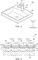
- FIG. 1 is a perspective view schematically illustrating a wet-area equipment including a wet-area device according to the embodiment.
- the wet-area equipment 500 includes the wet-area device 100 and a bowl 200.
- the wet-area device 100 is, for example, a device including a flow channel inside which water flows.
- the wet-area device 100 may be a device that is used at the periphery of a device including a flow channel inside which water flows and has a possibility of being contacted by water.
- the wet-area device 100 is a faucet apparatus.
- the wet-area device 100 includes a water discharger 101, a supporter 102, and an operation part 103.
- the water discharger 101 discharges water toward the bowl 200 positioned below the water discharger 101.
- the supporter 102 is provided below the water discharger 101.
- the supporter 102 is fixed to the upper surface of the bowl 200 at the lower end of the supporter 102 and supports the water discharger 101.
- a flow channel in which water flows is provided inside the water discharger 101 and the supporter 102.
- the operation part 103 is a lever provided above the water discharger 101. By operating the operation part 103, a user can discharge and stop the discharge of water from the water discharger 101, perform a temperature regulation and/or a flow regulation of the discharged water, etc.
- the wet-area device 100 is not limited to a faucet apparatus and may be, for example, a drainage metal fitting mounted to the bowl 200, a handrail provided in a bath room, a toilet paper holder provided for a toilet, a handle provided in a kitchen, etc.
- FIG. 2 is a cross-sectional view schematically illustrating the outer surface vicinity of the wet-area device according to the embodiment.
- the wet-area device 100 includes a main part 40, a first layer 10, a second layer 20, and a third layer 30.
- the main part 40 is made of metal.
- the main part 40 includes, for example, a copper alloy such as brass or the like, stainless steel, etc.
- the main part 40 may include, for example, copper plating on the outer surface of a base made of zinc.
- the first layer 10 is provided on an outer surface 40a of the main part 40. In other words, the first layer 10 is provided outward of the outer surface 40a of the main part 40.
- the first layer 10 may be directly provided on the outer surface 40a of the main part 40 or may be indirectly provided on the outer surface 40a of the main part 40 with another layer interposed. That is, the first layer 10 may contact the outer surface 40a of the main part 40 or may not contact the outer surface 40a of the main part 40. In the example, the first layer 10 contacts the outer surface 40a of the main part 40.
- the first layer 10 is made of metal.
- the first layer 10 includes, for example, nickel, copper, etc.
- the corrosion resistance of the wet-area device 100 can be improved by providing the first layer 10.
- the first layer 10 includes a first unevenness 11 in an outer surface 10a side.
- the first unevenness 11 is provided at a side of the outer surface 10a of the first layer 10.
- the first unevenness 11 includes multiple recesses 11a (first recesses) and multiple protrusions 11b (first protrusions).
- the recesses 11a of the first unevenness 11 are recessed in the stacking direction.
- the protrusions 11b of the first unevenness 11 protrude in the stacking direction.
- the "stacking direction” is a direction connecting the main part 40 and the first layer 10. That is, the stacking direction is a direction orthogonal to the outer surface 10a of the first layer 10.
- the second layer 20 is provided on the outer surface 10a of the first layer 10.
- the second layer 20 is provided outward of the outer surface 10a of the first layer 10.
- the second layer 20 is stacked in the same direction as the first layer 10. That is, the first layer 10 is positioned between the main part 40 and the second layer 20 in the stacking direction.
- the second layer 20 is positioned at the outermost surface.
- the second layer 20 may be directly provided on the outer surface 10a of the first layer 10 or may be indirectly provided on the outer surface 10a of the first layer 10 with another layer (e.g., the third layer 30) interposed. That is, the second layer 20 may contact the outer surface 10a of the first layer 10 or may not contact the outer surface 10a of the first layer 10. In the example, the second layer 20 does not contact the outer surface 10a of the first layer 10.
- the second layer 20 is made of metal.
- the second layer 20 includes, for example, chromium carbonitride, chrome, nickel, a tin-cobalt alloy, gold, etc.
- the hardness of the second layer 20 is greater than the hardness of the first layer 10.
- the hardness of the first layer 10 and the hardness of the second layer 20 can be measured by a measurement method conforming to JIS Z 2244:2009.
- the second layer 20 includes chromium carbonitride
- the second layer 20 is, for example, black.
- the outer surface of the wet-area device 100 can be colored by providing the second layer 20.
- the second layer 20 functions as a colored layer.
- the wear resistance of the wet-area device 100 can be improved by providing the second layer 20, and the outer surface of the wet-area device 100 can be provided with metallic luster.
- the second layer 20 includes a second unevenness 21 in an outer surface 20a side.
- the second unevenness 21 is provided at a side of the outer surface 20a of the second layer 20.
- the second unevenness 21 includes multiple recesses 21a (second recesses) and multiple protrusions 21b (second protrusions).
- the recesses 21a of the second unevenness 21 are recessed in the stacking direction.
- the protrusions 21b of the second unevenness 21 protrude in the stacking direction.
- the second unevenness 21 is formed along the first unevenness 11.
- the second unevenness 21 is arranged along the first unevenness 11.
- the second unevenness 21 follows the first unevenness 11. That is, the recesses 21a of the second unevenness 21 overlap the recesses 11a of the first unevenness 11 in the stacking direction. Also, the protrusions 21b of the second unevenness 21 overlap the protrusions 11b of the first unevenness 11 in the stacking direction.
- the glossy appearance of the outer surface of the wet-area device 100 can be matted so as not to be too glossy.
- the third layer 30 is provided between the first layer 10 and the second layer 20 in the stacking direction. That is, the third layer 30 is provided on the outer surface 10a of the first layer 10 and under the outer surface 20a of the second layer 20. In other words, the third layer 30 is provided outward of the outer surface 10a of the first layer 10 and inward of the outer surface 20a of the second layer 20.
- the third layer 30 is stacked in the same direction as the first layer 10 and the second layer 20.
- the third layer 30 may be directly provided on the outer surface 10a of the first layer 10 or may be indirectly provided on the outer surface 10a of the first layer 10 with another layer interposed. That is, the third layer 30 may contact the outer surface 10a of the first layer 10 or may not contact the outer surface 10a of the first layer 10. In the example, the third layer 30 contacts the outer surface 10a of the first layer 10.
- the second layer 20 may be directly provided on an outer surface 30a of the third layer 30 or may be indirectly provided on the outer surface 30a of the third layer 30 with another layer interposed. That is, the second layer 20 may contact the outer surface 30a of the third layer 30 or may not contact the outer surface 30a of the third layer 30. In the example, the second layer 20 contacts the outer surface 30a of the third layer 30.
- the third layer 30 is made of metal.
- the third layer 30 includes, for example, chrome, nickel, a tin-cobalt alloy, gold, etc.
- the wear resistance of the wet-area device 100 can be improved, and the outer surface of the wet-area device 100 can be provided with metallic luster.
- the third layer 30 is provided as necessary and is omissible.
- the third layer 30 includes a third unevenness 31 in the outer surface 30a side.
- the third unevenness 31 is provided at a side of the outer surface 30a of the third layer 30.
- the third unevenness 31 includes multiple recesses 31a (third recesses) and multiple protrusions 31b (third protrusions).
- the recesses 31a of the third unevenness 31 are recessed in the stacking direction.
- the protrusions 31b of the third unevenness 31 protrude in the stacking direction.
- the third unevenness 31 is formed along the first unevenness 11.
- the third unevenness 31 is arranged along the first unevenness 11.
- the third unevenness 31 follows the first unevenness 11. That is, the recesses 31a of the third unevenness 31 overlap the recesses 11a of the first unevenness 11 in the stacking direction. Also, the protrusions 31b of the third unevenness 31 overlap the protrusions 11b of the first unevenness 11 in the stacking direction.
- the second layer 20 (the second unevenness 21) can reflect the first unevenness 11 via the third unevenness 31 because the third layer 30 includes the third unevenness 31 along the first unevenness 11; therefore, the adhesion of grime due to the unevenness can be suppressed while suppressing the glossy appearance of the outer surface by matting.
- the main part 40 includes a main part unevenness 41 in the outer surface 40a side.
- the main part unevenness 41 is provided at a side of the outer surface 40a of the main part 40.
- the main part unevenness 41 includes multiple recesses 41a (main part recesses) and multiple protrusions 41b (main part protrusions).
- the recesses 41a of the main part unevenness 41 are recessed in the stacking direction.
- the protrusions 41b of the main part unevenness 41 protrude in the stacking direction.
- the main part unevenness 41 is formed along the first unevenness 11.
- the main part unevenness 41 is arranged along the first unevenness 11.
- the main part unevenness 41 follows the first unevenness 11. That is, the recesses 41a of the main part unevenness 41 overlap the recesses 11a of the first unevenness 11 in the stacking direction. Also, the protrusions 41b of the main part unevenness 41 overlap the protrusions 11b of the first unevenness 11 in the stacking direction.
- the main part 40 may not include the main part unevenness 41. That is, the outer surface 40a of the main part 40 may be planar.
- a thickness T2 of the second layer 20 is, for example, less than a thickness T1 of the first layer 10.
- the second unevenness 21 can be formed better along the first unevenness 11 by setting the thickness T2 of the second layer 20 to be less than the thickness T1 of the first layer 10. Thereby, it is easy to adjust the glossy appearance of the outer surface in a moderate range.
- a thickness T3 of the third layer 30 is, for example, less than the thickness T2 of the second layer 20.
- the thickness T1 of the first layer 10 is, for example, greater than the thickness T3 of the third layer 30.
- the thickness T1 of the first layer 10 is, for example, not less than 2 ⁇ m and not more than 30 ⁇ m.
- the thickness T2 of the second layer 20 is, for example, not less than 0.1 ⁇ m and not more than 3.0 ⁇ m (e.g., about 1 ⁇ m).
- the thickness T3 of the third layer 30 is, for example, not less than 0.1 ⁇ m and not more than 2.0 ⁇ m (e.g., about 0.5 ⁇ m).
- thickness is the length in the stacking direction.
- the thickness can be calculated as the average value of lengths in the stacking direction at multiple locations in a cross-sectional image obtained with a scanning electron microscope (SEM).
- first layer 10 it is sufficient for the first layer 10 to be provided on at least a portion of the outer surface 40a of the main part 40, and it is favorable to be provided on the entire surface of the outer surface 40a of the main part 40. Also, it is sufficient for the second layer 20 to be provided on at least a portion of the outer surface 10a of the first layer 10, and it is favorable to be provided on the entire surface of the outer surface 10a of the first layer 10.
- third layer 30 it is sufficient for the third layer 30 to be provided on at least a portion of the outer surface 10a of the first layer 10, and it is favorable to be provided on the entire surface of the outer surface 10a of the first layer 10.
- first unevenness 11 is provided in at least a portion of the outer surface 10a side of the first layer 10, and it is favorable to be provided in the entire surface on the outer surface 10a side of the first layer 10.
- second unevenness 21 is provided in at least a portion of the outer surface 20a side of the second layer 20, and it is favorable to be provided in the entire surface on the outer surface 20a side of the second layer 20.
- third layer 30 is provided, it is sufficient for the third unevenness 31 to be provided in at least a portion of the outer surface 30a side of the third layer 30, and it is favorable to be provided in the entire surface on the outer surface 30a side of the third layer 30.
- the main part unevenness 41 is provided in the main part 40, it is sufficient for the main part unevenness 41 to be provided in at least a portion of the outer surface 40a side of the main part 40, and it is favorable to be provided in the entire surface on the outer surface 40a side of the main part 40.
- a layer that includes chrome, nickel, a tin-cobalt alloy, gold, etc. also may be provided between the first layer 10 and the third layer 30 and/or between the third layer 30 and the second layer 20. Even when such a layer is provided, by forming an unevenness in the outer surface side of this layer along the unevenness of the layer therebelow, the layer above this layer can reflect the first unevenness 11 via the unevenness of this layer.
- FIG. 3 is a schematic view illustrating an average height Rc of an unevenness.
- an average height Rc (Rc1) of the first unevenness 11 of the first layer 10 is described as an example in FIG. 3
- an average height Rc3 of the third unevenness 31 of the third layer 30 and an average height Rc4 of the main part unevenness 41 of the main part 40 also can be calculated similarly to the average height Rc1 of the first unevenness 11.
- the average height Rc of the unevenness is the average value of a height Zt i of each contour curve element along a reference length L and is represented by Formula (1) recited below.
- the "contour curve element” is one set of a recess and a protrusion that are next to each other. More specifically, for example, as illustrated in FIG.
- the average height Rc is the average value of heights Zt1 to Zt m of m contour curve elements included within the reference length L, wherein the height Zt i (e.g., Zt1, Zt2, Zt3, Zt m , etc.) of each contour curve element is the length in the stacking direction from the bottom of one recess 11a included in the first unevenness 11 of the first layer 10 to the apex of the protrusion 11b next to the recess 11a.
- FIG. 4 is a schematic view illustrating an average length RS m of the unevenness.
- an average length RS m (RS m 1) of the first unevenness 11 of the first layer 10 is described as an example in FIG. 4
- an average length RS m 4 of the main part unevenness 41 of the main part 40 also can be calculated similarly to the average length RS m 1 of the first unevenness 11.
- the average length RSm of the unevenness is the average value of a length X si of each contour curve element along the reference length L and is represented by Formula (2) recited below. More specifically, for example, as illustrated in FIG. 4 , the average length RSm is the average value of lengths Xs1 to Xs m of m contour curve elements included within the reference length L, wherein the length X si (e.g., Xs1, Xs2, Xs3, etc.) of each contour curve element is the length in the measurement direction (a direction orthogonal to the stacking direction) from the apex of one protrusion 11b included in the first unevenness 11 of the first layer 10 to the apex of the protrusion 11b next to the protrusion 11b.
- the average height Rc of the unevenness and the average length RS m can be measured using the surface roughness tester SV-3200L4 manufactured by Mitutoyo.
- the average height Rc1 of the first unevenness 11 is less than the average length RS m 1 of the first unevenness 11. That is, the average value of the depths (the heights) of the multiple recesses 11a included in the first unevenness 11 is less than the average value of the widths of the multiple recesses 11a included in the first unevenness 11.
- the glossy appearance of the outer surface of the wet-area device 100 can be matted so as not to be too glossy, and the height of the unevenness of the outer surface of the wet-area device 100 can be prevented from becoming too large. Thereby, the adhesion of grime due to the unevenness can be suppressed while suppressing the glossy appearance of the outer surface by matting.
- the average height Rc1 of the first unevenness 11 is less than the average length RS m 1 of the first unevenness 11 for at least a portion of the first layer 10, and it is favorable for the average height Rc1 of the first unevenness 11 to be less than the average length RS m 1 of the first unevenness 11 for the entire first layer 10.
- the wet-area device 100 is a faucet apparatus, for example, it is favorable to perform matting so that the average height Rc1 of the first unevenness 11 is less than the average length RS m 1 of the first unevenness 11 for the upper surface of the water discharger 101, the upper surface of the operation part 103, the front and side surfaces of the supporter 102, etc., that are easily viewable by the user.
- the average height Rc1 of the first unevenness 11 is, for example, greater than 1 ⁇ m, and favorably greater than 1.3 ⁇ m and less than 5.7 ⁇ m.
- the average length RS m 1 of the first unevenness 11 is, for example, not less than 60 ⁇ m and not more than 200 ⁇ m, and favorably greater than 93 ⁇ m and less than 126 ⁇ m.
- the ratio ( Rc1 / RSm1 ) of the average height Rc1 of the first unevenness 11 to the average length RS m 1 of the first unevenness 11 is, for example, greater than 0.01 and less than 0.05.
- the average height Rc1 of the first unevenness 11 By setting the average height Rc1 of the first unevenness 11 to be in this range, the height of the unevenness of the outer surface of the wet-area device 100 can be prevented from becoming too large or too small. Thereby, a moderate glossy appearance (gloss) can remain while suppressing the glossy appearance of the outer surface by matting.
- the ratio ( Rc1 / RSm1 ) of the average height Rc1 of the first unevenness 11 to the average length RS m 1 of the first unevenness 11 is favorable for the ratio ( Rc1 / RSm1 ) of the average height Rc1 of the first unevenness 11 to the average length RS m 1 of the first unevenness 11 to be greater than 0.014 and less than 0.045, and more favorably not less than 0.015 and not more than 0.039.
- the ratio of the average height Rc1 of the first unevenness 11 to the average length RS m 1 of the first unevenness 11 can be in this range, the height of the unevenness of the outer surface of the wet-area device 100 can be further prevented from becoming too large or too small. Thereby, an appearance that is both glossy and matte can be realized at the outer surface of the wet-area device 100.
- the second unevenness 21 of the second layer 20 is along the first unevenness 11 of the first layer 10.
- the average height Rc2 of the second unevenness 21 is less than the average length RS m 2 of the second unevenness 21. That is, the average value of the depths (the heights) of the multiple recesses 21a included in the second unevenness 21 is less than the average value of the widths of the multiple recesses 21a included in the second unevenness 21.
- the average height Rc2 of the second unevenness 21 is, for example, greater than 1 ⁇ m, and favorably greater than 1.5 ⁇ m and less than 6.2 ⁇ m.
- the average length RS m 2 of the second unevenness 21 is, for example, not less than 60 ⁇ m and not more than 200 ⁇ m, and favorably greater than 97 ⁇ m and less than 136 ⁇ m.
- the ratio (Rc2 / RSm2) of the average height Rc2 of the second unevenness 21 to the average length RS m 2 of the second unevenness 21 is, for example, greater than 0.01 and less than 0.05.
- the average height Rc2 of the second unevenness 21 By setting the average height Rc2 of the second unevenness 21 to be in this range, the height of the unevenness of the outer surface of the wet-area device 100 can be prevented from becoming too large or too small. Thereby, a moderate glossy appearance (gloss) can remain while suppressing the glossy appearance of the outer surface by matting.
- the ratio ( Rc2 / RSm2 ) of the average height Rc2 of the second unevenness 21 to the average length RS m 2 of the second unevenness 21 is favorable for the ratio ( Rc2 / RSm2 ) of the average height Rc2 of the second unevenness 21 to the average length RS m 2 of the second unevenness 21 to be greater than 0.015 and less than 0.046, and more favorably not less than 0.016 and not more than 0.038.
- the ratio of the average height Rc2 of the second unevenness 21 to the average length RS m 2 of the second unevenness 21 can be in this range, the height of the unevenness of the outer surface of the wet-area device 100 can be further prevented from becoming too large or too small. Thereby, an appearance that is both glossy and matte can be realized at the outer surface of the wet-area device 100.
- the third unevenness 31 of the third layer 30 is along the first unevenness 11 of the first layer 10.
- the average height Rc3 of the third unevenness 31 is less than the average length RS m 3 of the third unevenness 31. That is, the average value of the depths (the heights) of the multiple recesses 31a included in the third unevenness 31 is less than the average value of the widths of the multiple recesses 31a included in the third unevenness 31.
- the average height Rc3 of the third unevenness 31 is, for example, 1 ⁇ m or more, and favorably greater than 1.3 ⁇ m and less than 5.7 ⁇ m.
- the average length RS m 3 of the third unevenness 31 is, for example, not less than 60 ⁇ m and not more than 200 ⁇ m, and favorably greater than 93 ⁇ m and less than 126 ⁇ m.
- the ratio ( Rc3 / RSm3 ) of the average height Rc3 of the third unevenness 31 to the average length RS m 3 of the third unevenness 31 is, for example, greater than 0.01 and less than 0.05, and favorably greater than 0.014 and less than 0.045.
- the average height Rc3 of the third unevenness 31 By setting the average height Rc3 of the third unevenness 31 to be in this range, the height of the unevenness of the outer surface of the wet-area device 100 can be prevented from becoming too large or too small when the third layer 30 is provided. Thereby, a moderate glossy appearance (gloss) can remain while suppressing the glossy appearance of the outer surface by matting.
- the main part unevenness 41 of the main part 40 is along the first unevenness 11 of the first layer 10.
- the average height Rc4 of the main part unevenness 41 is less than the average length RS m 4 of the main part unevenness 41. That is, the average value of the depths (the heights) of the multiple recesses 41a included in the main part unevenness 41 is less than the average value of the widths of the multiple recesses 41a included in the main part unevenness 41.
- the average height Rc4 of the main part unevenness 41 is, for example, 1 ⁇ m or more, and favorably greater than 1 ⁇ m and less than 6.3 ⁇ m.
- the average length RSm4 of the main part unevenness 41 is, for example, not less than 60 ⁇ m and not more than 200 ⁇ m, and favorably not less than 90 ⁇ m and not more than 150 ⁇ m.
- the ratio ( Rc4 / RSm4 ) of the average height Rc4 of the main part unevenness 41 to the average length RS m 4 of the main part unevenness 41 is, for example, greater than 0.01 and less than 0.05.
- the average height Rc1 of the first unevenness 11 is, for example, greater than the thickness T2 of the second layer 20 (referring to FIG. 2 ).
- the second unevenness 21 can be formed better along the first unevenness 11. Thereby, it is easy to adjust the glossy appearance of the outer surface in a moderate range.
- FIGS. 5A to 5C are cross-sectional views schematically illustrating the method for manufacturing the wet-area device according to the embodiment.
- FIGS. 6A and 6B are cross-sectional views schematically illustrating the method for manufacturing the wet-area device according to the embodiment.
- the main part 40 that is made of metal is prepared as illustrated in FIG. 5A .
- the first layer 10 is formed on the outer surface 40a of the main part 40 (a first layer formation process).
- the first layer 10 is formed by electroplating, etc.
- the other layer may be formed on the outer surface 40a of the main part 40 before the first layer formation process.
- the first unevenness 11 that includes the multiple recesses 11a and the multiple protrusions 11b is formed in the outer surface 10a side of the first layer 10 by shot blasting the outer surface 10a of the first layer 10 (an unevenness formation process).
- the average height Rc1 of the first unevenness 11 is set to be less than the average length RS m 1 of the first unevenness 11.
- the average height Rc1 of the first unevenness 11 and the average length RS m 1 can be adjusted by modifying the processing conditions of the shot blasting. More specifically, the average height Rc1 of the first unevenness 11 and the average length RS m 1 can be adjusted by modifying the particle size of the blasting media (the grain) and/or the rate (the pressure of the air) at which the blasting media is projected.
- the main part unevenness 41 is formed in the outer surface 40a side of the main part 40 to include the multiple recesses 41a and the multiple protrusions 41b along the first unevenness 11.
- the main part unevenness 41 may not be formed in the main part 40 in the unevenness formation process.
- the third layer 30 is formed on the outer surface 10a of the first layer 10 in which the first unevenness 11 is formed (a third layer formation process).
- the third layer 30 is formed by electroplating, etc.
- the third layer formation process forms the third layer 30 so that the third unevenness 31 includes the multiple recesses 31a and the multiple protrusions 31b and is formed along the first unevenness 11 in the outer surface 30a side of the third layer 30.
- the third layer formation process is performed as necessary and is omissible.
- the other layer may be formed on the outer surface 10a of the first layer 10 after the first layer formation process and before the third layer formation process.
- the second layer 20 that has a higher hardness than the first layer 10 is formed on the outer surface 30a of the third layer 30 (a second layer formation process).
- the second layer 20 includes chromium carbonitride and is formed by, for example, chemical vapor deposition (CVD), physical vapor deposition (PVD), sputtering, etc.
- the second layer formation process forms the second layer 20 so that the second unevenness 21 includes the multiple recesses 21a and the multiple protrusions 21b and is formed along the first unevenness 11 in the outer surface 20a side of the second layer 20.
- the second layer 20 is formed so that the thickness T2 of the second layer 20 is less than the thickness T1 of the first layer 10 and less than the average height Rc1 of the first unevenness 11.
- the other layer may be formed on the outer surface 30a of the third layer 30 after the third layer formation process and before the second layer formation process.
- the glossy appearance of the outer surface of the wet-area device 100 can be matted so as not to be too glossy.
- the glossy appearance of the outer surface of the wet-area device 100 can be matted so as not to be too glossy by forming the third unevenness 31 along the first unevenness 11 in the third layer 30.
- the glossy appearance of the outer surface of the wet-area device 100 can be matted so as not to be too glossy, and the height of the unevenness of the outer surface of the wet-area device 100 can be prevented from becoming too large.
- a wet-area device can be provided in which the adhesion of grime due to the unevenness can be suppressed while suppressing the glossy appearance of the outer surface by matting.
- the unevenness in the outermost surface of the wet-area device 100 for example, it may be considered to perform the unevenness formation process after the second layer formation process or the third layer formation process.
- it may be considered to perform the unevenness formation process after the second layer formation process or the third layer formation process.
- cracks or the like may occur in the outer surface of the second layer 20 and/or the third layer 30 when shot blasting the second layer 20 and/or the third layer 30.
- the unevenness formation process is performed after the first layer formation process and before the second layer formation process (before the third layer formation process).
- the matting can be performed so that a moderate glossy appearance remains in the outer surface of the wet-area device 100 while suppressing the occurrence of cracks, etc., in the outer surface of the wet-area device 100.
- the inventors performed the following experiment for the relationship between the appearance and the first and second unevennesses 11 and 21.
- samples 1 to 16 were prepared in which the first layer 10 that included nickel was formed on the outer surface 40a of the main part 40.
- the first unevenness 11 was formed in the first layer 10 to have various average heights Rc and average lengths RSm by performing shot blasting with different processing conditions for each of the samples 1 to 16.
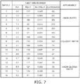
- the average height Rc1 of the first unevenness 11 After forming the first unevenness 11 in the first layer 10 for the samples 1 to 16, the average height Rc1 of the first unevenness 11, the average length RS m 1, the ratio ( Rc1 / RSm1 ) of the average height Rc1 to the average length RSm1, and the glossiness were measured, and the existence of glossiness and matte in the appearance was determined by confirming the appearance with the naked eye. The results are shown in FIG. 7 .
- the third layer 30 that included chrome was formed on the outer surface 10a of the first layer 10 in which the first unevenness 11 was formed.
- the second layer 20 that included chromium carbonitride was formed by PVD on the outer surface 30a of the third layer 30 for each of the samples 1 to 16.
- FIGS. 7 and 8 are tables illustrating the experiment results.
- the ratio ( Rc1 / RSm1 ) of the average height Rc1 to the average length RS m 1 of the first unevenness 11 was 0.005 to 0.014
- the ratio (Rc2 / RSm2) of the average height Rc2 to the average length RSm2 of the second unevenness 21 was 0.005 to 0.015.
- the appearances of the samples 1 to 4 after the second layer 20 was formed were "non-matte", in which the appearance was glossy but was without matte.
- the ratio ( Rc1 / RSm1 ) of the average height Rc1 to the average length RS m 1 of the first unevenness 11 was 0.045 to 0.082
- the ratio (Rc2 / RSm2) of the average height Rc2 to the average length RS m 2 of the second unevenness 21 was 0.046 to 0.090.
- the appearances of the samples 12 to 16 after the second layer 20 was formed were "non-glossy matte", in which the appearance was matte but had no gloss.
- the ratio ( Rc1 / RSm1 ) of the average height Rc1 to the average length RS m 1 of the first unevenness 11 was 0.015 to 0.039 (greater than 0.014 and less than 0.045)
- the ratio ( Rc2 / RSm2 ) of the average height Rc2 to the average length RS m 2 of the second unevenness 21 was 0.016 to 0.038 (greater than 0.015 and less than 0.046).
- the appearances of the samples 5 to 11 after the second layer 20 was formed were "glossy-matte", in which an appearance that is both glossy and matte existed.
- a wet-area device and a method for manufacturing a wet-area device can be provided in which the adhesion of grime due to the unevenness can be suppressed while suppressing the glossy appearance of the outer surface by matting.
Landscapes
- Chemical & Material Sciences (AREA)
- Engineering & Computer Science (AREA)
- Mechanical Engineering (AREA)
- Chemical Kinetics & Catalysis (AREA)
- Organic Chemistry (AREA)
- Metallurgy (AREA)
- Materials Engineering (AREA)
- Inorganic Chemistry (AREA)
- Water Supply & Treatment (AREA)
- Health & Medical Sciences (AREA)
- Public Health (AREA)
- Hydrology & Water Resources (AREA)
- Life Sciences & Earth Sciences (AREA)
- Environmental & Geological Engineering (AREA)
- Electrochemistry (AREA)
- Domestic Plumbing Installations (AREA)
- Electroplating Methods And Accessories (AREA)
- Laminated Bodies (AREA)
- Moulds For Moulding Plastics Or The Like (AREA)
- Cookers (AREA)
Abstract
According to one embodiment, a wet-area device includes a main part, a first layer, and a second layer. The first layer is provided on an outer surface of the main part. The second layer is provided on an outer surface of the first layer. A hardness of the second layer is greater than a hardness of the first layer. The first layer includes a first unevenness at a side of the outer surface of the first layer. The first unevenness includes a plurality of recesses and a plurality of protrusions. The second layer includes a second unevenness at a side of an outer surface of the second layer. The second unevenness includes a plurality of recesses and a plurality of protrusions. The second unevenness is arranged along the first unevenness. An average height of the first unevenness is less than an average length of the first unevenness.
Description
- This application is based upon and claims the benefit of priority from Japanese Patent Application No.
2019-216624, filed on November 29, 2019 2020-117791, filed on July 8, 2020 - Embodiments described herein relate generally to a wet-area device and a method for manufacturing a wet-area device.
- Metal plating on the outer surface of a main part for ensuring the strength of a wet-area device such as a faucet apparatus or the like is known. The outer surface of such a wet-area device has a highly glossy appearance due to the plating when struck by light.
- On the other hand, matting of the outer surface of a plated wet-area device for suppressing the glossy appearance of the outer surface is known. For example, such matting is performed by forming a fine unevenness in the outer surface of the wet-area device (the plating) by shot blasting, etc.
- However, when matting is performed by shot blasting or the like, there are cases where the height (the depth) of the unevenness formed in the outer surface of the wet-area device undesirably becomes too large. When the height of the unevenness formed in the outer surface of the wet-area device is too large, it is difficult to remove the water that collects in the unevenness, and the adhesion of grime to the outer surface of the wet-area device easily becomes a problem.
- According to the embodiment, a wet-area device includes a main part, a first layer, and a second layer. The main part is made of metal. The first layer is provided on an outer surface of the main part. The second layer is provided on an outer surface of the first layer. A hardness of the second layer is greater than a hardness of the first layer. The first layer includes a first unevenness at a side of the outer surface of the first layer. The first unevenness includes a plurality of first recesses and a plurality of first protrusions. The second layer includes a second unevenness at a side of an outer surface of the second layer. The second unevenness includes a plurality of second recesses and a plurality of second protrusions. The second unevenness is arranged along the first unevenness. An average height of the first unevenness is less than an average length of the first unevenness.
-
-
FIG. 1 is a perspective view schematically illustrating a wet-area equipment including a wet-area device according to the embodiment; -
FIG. 2 is a cross-sectional view schematically illustrating the outer surface vicinity of the wet-area device according to the embodiment; -
FIG. 3 is a schematic view illustrating an average height Rc of an unevenness; -
FIG. 4 is a schematic view illustrating an average length RSm of the unevenness; -
FIGS. 5A to 5C are cross-sectional views schematically illustrating the method for manufacturing the wet-area device according to the embodiment; -
FIGS. 6A and 6B are cross-sectional views schematically illustrating the method for manufacturing the wet-area device according to the embodiment; -
FIG. 7 is a table illustrating the experiment results; and -
FIG. 8 is a table illustrating the experiment results. - A first invention is a wet-area device including a main part made of metal, a first layer provided on an outer surface of the main part, and a second layer provided on an outer surface of the first layer; a hardness of the second layer is greater than a hardness of the first layer; the first layer includes a first unevenness, which includes multiple first recesses and multiple first protrusions, at a side of the outer surface of the first layer; the second layer includes a second unevenness, which includes multiple second recesses and multiple second protrusions, arranged along the first unevenness at a side of an outer surface of the second layer; and an average height of the first unevenness is less than an average length of the first unevenness.
- According to this wet-area device, the glossy appearance of the outer surface of the wet-area device can be matted so as not to be too glossy because the first layer includes the first unevenness, and the second layer includes the second unevenness along the first unevenness. By setting the average height of the first unevenness to be less than the average length of the first unevenness, the glossy appearance of the outer surface of the wet-area device can be matted to be not too glossy, and the height of the unevenness of the outer surface of the wet-area device can be prevented from becoming too large. Thereby, the adhesion of grime due to the unevenness can be suppressed while suppressing the glossy appearance of the outer surface by matting.
- A second invention is the wet-area device of the first invention, wherein the average height of the first unevenness is greater than 1 µm, and a ratio of the average height of the first unevenness to the average length of the first unevenness is greater than 0.01 and less than 0.05.
- According to this wet-area device, by setting the average height of the first unevenness to be in this range, the height of the unevenness of the outer surface of the wet-area device can be prevented from becoming too large or too small. Thereby, a moderate glossy appearance (gloss) can remain while suppressing the glossy appearance of the outer surface by matting.
- A third invention is the wet-area device of the second invention, wherein the ratio of the average height of the first unevenness to the average length of the first unevenness is greater than 0.014 and less than 0.045.
- According to this wet-area device, by setting the ratio of the average height of the first unevenness to the average length of the first unevenness to be in this range, the height of the unevenness of the outer surface of the wet-area device can be further prevented from becoming too large or too small. Thereby, an appearance that is both glossy and matte can be realized at the outer surface of the wet-area device.
- A fourth invention is the wet-area device of the third invention, wherein the ratio of the average height of the first unevenness to the average length of the first unevenness is not less than 0.015 and not more than 0.039.
- According to this wet-area device, by setting the ratio of the average height of the first unevenness to the average length of the first unevenness to be in this range, the height of the unevenness of the outer surface of the wet-area device can be further prevented from becoming too large or too small. Thereby, an appearance that is both glossy and matte can be realized at the outer surface of the wet-area device.
- A fifth invention is the wet-area device of any one of the first to fourth inventions, wherein an average height of the second unevenness is greater than 1 µm, and a ratio of the average height of the second unevenness to an average length of the second unevenness is greater than 0.01 and less than 0.05.
- According to this wet-area device, by setting the average height of the second unevenness to be in this range, the height of the unevenness of the outer surface of the wet-area device can be prevented from becoming too large or too small. Thereby, a moderate glossy appearance (gloss) can remain while suppressing the glossy appearance of the outer surface by matting.
- A sixth invention is the wet-area device of the fifth invention, wherein the ratio of the average height of the second unevenness to the average length of the second unevenness is greater than 0.015 and less than 0.046.
- According to this wet-area device, by setting the ratio of the average height of the second unevenness to the average length of the second unevenness to be in this range, the height of the unevenness of the outer surface of the wet-area device can be further prevented from becoming too large or too small. Thereby, an appearance that is both glossy and matte can be realized at the outer surface of the wet-area device.
- A seventh invention is the wet-area device of a sixth invention, wherein the ratio of the average height of the second unevenness to the average length of the second unevenness is not less than 0.016 and not more than 0.038.
- According to this wet-area device, by setting the ratio of the average height of the second unevenness to the average length of the second unevenness to be in this range, the height of the unevenness of the outer surface of the wet-area device can be further prevented from becoming too large or too small. Thereby, an appearance that is both glossy and matte can be realized at the outer surface of the wet-area device.
- An eighth invention is the wet-area device of any one of the first to seventh inventions, wherein a thickness of the second layer is less than a thickness of the first layer.
- According to this wet-area device, by setting the thickness of the second layer to be less than the thickness of the first layer, the second unevenness can be formed better along the first unevenness. Thereby, it is easy to adjust the glossy appearance of the outer surface in a moderate range.
- A ninth invention is the wet-area device of the eighth invention, wherein the average height of the first unevenness is greater than the thickness of the second layer.
- According to this wet-area device, by setting the average height of the first unevenness to be greater than the thickness of the second layer, the second unevenness can be formed better along the first unevenness. Thereby, it is easy to adjust the glossy appearance of the outer surface in a moderate range.
- A tenth invention is a method for manufacturing the wet-area device of the first invention, including a first layer formation process of forming the first layer on the outer surface of a main part made of metal, an unevenness formation process of forming the first unevenness including the multiple first recesses and the multiple first protrusions at the side of the outer surface of the first layer by shot blasting the outer surface of the first layer, and a second layer formation process of forming the second layer having a higher hardness than the first layer on the outer surface of the first layer where the first unevenness is formed; an average height of the first unevenness is less than an average length of the first unevenness in the unevenness formation process; and the second layer formation process forms the second layer so that the second unevenness includes the multiple second recesses and the multiple second protrusions and is arranged along the first unevenness at the side of the outer surface of the second layer.
- According to the method for manufacturing the wet-area device, by forming the first unevenness in the first layer and by forming the second unevenness along the first unevenness in the second layer, the glossy appearance of the outer surface of the wet-area device can be matted so as not to be too glossy. Also, by setting the average height of the first unevenness to be less than the average length of the first unevenness, the glossy appearance of the outer surface of the wet-area device can be matted so as not to be too glossy, and the height of the unevenness of the outer surface of the wet-area device can be prevented from becoming too large. Thereby, a wet-area device can be provided in which the adhesion of grime due to the unevenness can be suppressed while suppressing the glossy appearance of the outer surface by matting.
- Embodiments of the invention will now be described with reference to the drawings. Similar components in the drawings are marked with the same reference numerals, and a detailed description is omitted as appropriate.
-
FIG. 1 is a perspective view schematically illustrating a wet-area equipment including a wet-area device according to the embodiment. - As illustrated in
FIG. 1 , the wet-area equipment 500 according to the embodiment includes the wet-area device 100 and abowl 200. The wet-area device 100 is, for example, a device including a flow channel inside which water flows. The wet-area device 100 may be a device that is used at the periphery of a device including a flow channel inside which water flows and has a possibility of being contacted by water. - In the example, the wet-
area device 100 is a faucet apparatus. The wet-area device 100 includes awater discharger 101, asupporter 102, and anoperation part 103. Thewater discharger 101 discharges water toward thebowl 200 positioned below thewater discharger 101. Thesupporter 102 is provided below thewater discharger 101. Thesupporter 102 is fixed to the upper surface of thebowl 200 at the lower end of thesupporter 102 and supports thewater discharger 101. A flow channel in which water flows is provided inside thewater discharger 101 and thesupporter 102. Theoperation part 103 is a lever provided above thewater discharger 101. By operating theoperation part 103, a user can discharge and stop the discharge of water from thewater discharger 101, perform a temperature regulation and/or a flow regulation of the discharged water, etc. - The wet-
area device 100 is not limited to a faucet apparatus and may be, for example, a drainage metal fitting mounted to thebowl 200, a handrail provided in a bath room, a toilet paper holder provided for a toilet, a handle provided in a kitchen, etc. -
FIG. 2 is a cross-sectional view schematically illustrating the outer surface vicinity of the wet-area device according to the embodiment. - As illustrated in
FIG. 2 , the wet-area device 100 includes amain part 40, afirst layer 10, asecond layer 20, and athird layer 30. - The
main part 40 is made of metal. Themain part 40 includes, for example, a copper alloy such as brass or the like, stainless steel, etc. Themain part 40 may include, for example, copper plating on the outer surface of a base made of zinc. - The
first layer 10 is provided on anouter surface 40a of themain part 40. In other words, thefirst layer 10 is provided outward of theouter surface 40a of themain part 40. - The
first layer 10 may be directly provided on theouter surface 40a of themain part 40 or may be indirectly provided on theouter surface 40a of themain part 40 with another layer interposed. That is, thefirst layer 10 may contact theouter surface 40a of themain part 40 or may not contact theouter surface 40a of themain part 40. In the example, thefirst layer 10 contacts theouter surface 40a of themain part 40. - For example, the
first layer 10 is made of metal. Thefirst layer 10 includes, for example, nickel, copper, etc. The corrosion resistance of the wet-area device 100 can be improved by providing thefirst layer 10. - The
first layer 10 includes afirst unevenness 11 in anouter surface 10a side. Thefirst unevenness 11 is provided at a side of theouter surface 10a of thefirst layer 10. Thefirst unevenness 11 includesmultiple recesses 11a (first recesses) andmultiple protrusions 11b (first protrusions). Therecesses 11a of thefirst unevenness 11 are recessed in the stacking direction. Theprotrusions 11b of thefirst unevenness 11 protrude in the stacking direction. Here, the "stacking direction" is a direction connecting themain part 40 and thefirst layer 10. That is, the stacking direction is a direction orthogonal to theouter surface 10a of thefirst layer 10. - The
second layer 20 is provided on theouter surface 10a of thefirst layer 10. In other words, thesecond layer 20 is provided outward of theouter surface 10a of thefirst layer 10. Thesecond layer 20 is stacked in the same direction as thefirst layer 10. That is, thefirst layer 10 is positioned between themain part 40 and thesecond layer 20 in the stacking direction. For example, thesecond layer 20 is positioned at the outermost surface. - The
second layer 20 may be directly provided on theouter surface 10a of thefirst layer 10 or may be indirectly provided on theouter surface 10a of thefirst layer 10 with another layer (e.g., the third layer 30) interposed. That is, thesecond layer 20 may contact theouter surface 10a of thefirst layer 10 or may not contact theouter surface 10a of thefirst layer 10. In the example, thesecond layer 20 does not contact theouter surface 10a of thefirst layer 10. - For example, the
second layer 20 is made of metal. Thesecond layer 20 includes, for example, chromium carbonitride, chrome, nickel, a tin-cobalt alloy, gold, etc. The hardness of thesecond layer 20 is greater than the hardness of thefirst layer 10. For example, the hardness of thefirst layer 10 and the hardness of thesecond layer 20 can be measured by a measurement method conforming to JIS Z 2244:2009. When thesecond layer 20 includes chromium carbonitride, thesecond layer 20 is, for example, black. In such a case, for example, the outer surface of the wet-area device 100 can be colored by providing thesecond layer 20. In other words, in such a case, for example, thesecond layer 20 functions as a colored layer. When thesecond layer 20 includes chrome, nickel, a tin-cobalt alloy, gold, etc., the wear resistance of the wet-area device 100 can be improved by providing thesecond layer 20, and the outer surface of the wet-area device 100 can be provided with metallic luster. - The
second layer 20 includes asecond unevenness 21 in anouter surface 20a side. Thesecond unevenness 21 is provided at a side of theouter surface 20a of thesecond layer 20. Thesecond unevenness 21 includesmultiple recesses 21a (second recesses) andmultiple protrusions 21b (second protrusions). Therecesses 21a of thesecond unevenness 21 are recessed in the stacking direction. Theprotrusions 21b of thesecond unevenness 21 protrude in the stacking direction. - The
second unevenness 21 is formed along thefirst unevenness 11. Thesecond unevenness 21 is arranged along thefirst unevenness 11. In other words, thesecond unevenness 21 follows thefirst unevenness 11. That is, therecesses 21a of thesecond unevenness 21 overlap therecesses 11a of thefirst unevenness 11 in the stacking direction. Also, theprotrusions 21b of thesecond unevenness 21 overlap theprotrusions 11b of thefirst unevenness 11 in the stacking direction. - Thus, because the
first layer 10 includes thefirst unevenness 11 and because thesecond layer 20 includes thesecond unevenness 21 along thefirst unevenness 11, the glossy appearance of the outer surface of the wet-area device 100 can be matted so as not to be too glossy. - The
third layer 30 is provided between thefirst layer 10 and thesecond layer 20 in the stacking direction. That is, thethird layer 30 is provided on theouter surface 10a of thefirst layer 10 and under theouter surface 20a of thesecond layer 20. In other words, thethird layer 30 is provided outward of theouter surface 10a of thefirst layer 10 and inward of theouter surface 20a of thesecond layer 20. Thethird layer 30 is stacked in the same direction as thefirst layer 10 and thesecond layer 20. - When the
third layer 30 is provided, thethird layer 30 may be directly provided on theouter surface 10a of thefirst layer 10 or may be indirectly provided on theouter surface 10a of thefirst layer 10 with another layer interposed. That is, thethird layer 30 may contact theouter surface 10a of thefirst layer 10 or may not contact theouter surface 10a of thefirst layer 10. In the example, thethird layer 30 contacts theouter surface 10a of thefirst layer 10. - When the
third layer 30 is provided, thesecond layer 20 may be directly provided on anouter surface 30a of thethird layer 30 or may be indirectly provided on theouter surface 30a of thethird layer 30 with another layer interposed. That is, thesecond layer 20 may contact theouter surface 30a of thethird layer 30 or may not contact theouter surface 30a of thethird layer 30. In the example, thesecond layer 20 contacts theouter surface 30a of thethird layer 30. - For example, the
third layer 30 is made of metal. Thethird layer 30 includes, for example, chrome, nickel, a tin-cobalt alloy, gold, etc. By providing thethird layer 30, the wear resistance of the wet-area device 100 can be improved, and the outer surface of the wet-area device 100 can be provided with metallic luster. Thethird layer 30 is provided as necessary and is omissible. - The
third layer 30 includes athird unevenness 31 in theouter surface 30a side. Thethird unevenness 31 is provided at a side of theouter surface 30a of thethird layer 30. Thethird unevenness 31 includesmultiple recesses 31a (third recesses) andmultiple protrusions 31b (third protrusions). Therecesses 31a of thethird unevenness 31 are recessed in the stacking direction. Theprotrusions 31b of thethird unevenness 31 protrude in the stacking direction. - The
third unevenness 31 is formed along thefirst unevenness 11. Thethird unevenness 31 is arranged along thefirst unevenness 11. In other words, thethird unevenness 31 follows thefirst unevenness 11. That is, therecesses 31a of thethird unevenness 31 overlap therecesses 11a of thefirst unevenness 11 in the stacking direction. Also, theprotrusions 31b of thethird unevenness 31 overlap theprotrusions 11b of thefirst unevenness 11 in the stacking direction. - Thus, when the
third layer 30 is provided, the second layer 20 (the second unevenness 21) can reflect thefirst unevenness 11 via thethird unevenness 31 because thethird layer 30 includes thethird unevenness 31 along thefirst unevenness 11; therefore, the adhesion of grime due to the unevenness can be suppressed while suppressing the glossy appearance of the outer surface by matting. - In the example, the
main part 40 includes amain part unevenness 41 in theouter surface 40a side. Themain part unevenness 41 is provided at a side of theouter surface 40a of themain part 40. Themain part unevenness 41 includesmultiple recesses 41a (main part recesses) andmultiple protrusions 41b (main part protrusions). Therecesses 41a of themain part unevenness 41 are recessed in the stacking direction. Theprotrusions 41b of themain part unevenness 41 protrude in the stacking direction. - The
main part unevenness 41 is formed along thefirst unevenness 11. Themain part unevenness 41 is arranged along thefirst unevenness 11. In other words, themain part unevenness 41 follows thefirst unevenness 11. That is, therecesses 41a of themain part unevenness 41 overlap therecesses 11a of thefirst unevenness 11 in the stacking direction. Also, theprotrusions 41b of themain part unevenness 41 overlap theprotrusions 11b of thefirst unevenness 11 in the stacking direction. - The
main part 40 may not include themain part unevenness 41. That is, theouter surface 40a of themain part 40 may be planar. - A thickness T2 of the
second layer 20 is, for example, less than a thickness T1 of thefirst layer 10. Thus, thesecond unevenness 21 can be formed better along thefirst unevenness 11 by setting the thickness T2 of thesecond layer 20 to be less than the thickness T1 of thefirst layer 10. Thereby, it is easy to adjust the glossy appearance of the outer surface in a moderate range. - A thickness T3 of the
third layer 30 is, for example, less than the thickness T2 of thesecond layer 20. The thickness T1 of thefirst layer 10 is, for example, greater than the thickness T3 of thethird layer 30. - More specifically, the thickness T1 of the
first layer 10 is, for example, not less than 2 µm and not more than 30 µm. The thickness T2 of thesecond layer 20 is, for example, not less than 0.1 µm and not more than 3.0 µm (e.g., about 1 µm). The thickness T3 of thethird layer 30 is, for example, not less than 0.1 µm and not more than 2.0 µm (e.g., about 0.5 µm). - Here, "thickness" is the length in the stacking direction. For example, the thickness can be calculated as the average value of lengths in the stacking direction at multiple locations in a cross-sectional image obtained with a scanning electron microscope (SEM).
- It is sufficient for the
first layer 10 to be provided on at least a portion of theouter surface 40a of themain part 40, and it is favorable to be provided on the entire surface of theouter surface 40a of themain part 40. Also, it is sufficient for thesecond layer 20 to be provided on at least a portion of theouter surface 10a of thefirst layer 10, and it is favorable to be provided on the entire surface of theouter surface 10a of thefirst layer 10. When thethird layer 30 is provided, it is sufficient for thethird layer 30 to be provided on at least a portion of theouter surface 10a of thefirst layer 10, and it is favorable to be provided on the entire surface of theouter surface 10a of thefirst layer 10. - It is sufficient for the
first unevenness 11 to be provided in at least a portion of theouter surface 10a side of thefirst layer 10, and it is favorable to be provided in the entire surface on theouter surface 10a side of thefirst layer 10. Also, it is sufficient for thesecond unevenness 21 to be provided in at least a portion of theouter surface 20a side of thesecond layer 20, and it is favorable to be provided in the entire surface on theouter surface 20a side of thesecond layer 20. When thethird layer 30 is provided, it is sufficient for thethird unevenness 31 to be provided in at least a portion of theouter surface 30a side of thethird layer 30, and it is favorable to be provided in the entire surface on theouter surface 30a side of thethird layer 30. When themain part unevenness 41 is provided in themain part 40, it is sufficient for themain part unevenness 41 to be provided in at least a portion of theouter surface 40a side of themain part 40, and it is favorable to be provided in the entire surface on theouter surface 40a side of themain part 40. - In the embodiment, a layer that includes chrome, nickel, a tin-cobalt alloy, gold, etc., also may be provided between the
first layer 10 and thethird layer 30 and/or between thethird layer 30 and thesecond layer 20. Even when such a layer is provided, by forming an unevenness in the outer surface side of this layer along the unevenness of the layer therebelow, the layer above this layer can reflect thefirst unevenness 11 via the unevenness of this layer. - The unevenness of each component will now be described in more detail.
-
FIG. 3 is a schematic view illustrating an average height Rc of an unevenness. - Although the average height Rc (Rc1) of the
first unevenness 11 of thefirst layer 10 is described as an example inFIG. 3 , an average height Rc2 of thesecond unevenness 21 of thesecond layer 20, an average height Rc3 of thethird unevenness 31 of thethird layer 30, and an average height Rc4 of themain part unevenness 41 of themain part 40 also can be calculated similarly to the average height Rc1 of thefirst unevenness 11. - As illustrated in
FIG. 3 , the average height Rc of the unevenness is the average value of a height Zti of each contour curve element along a reference length L and is represented by Formula (1) recited below. The "contour curve element" is one set of a recess and a protrusion that are next to each other. More specifically, for example, as illustrated inFIG. 3 , the average height Rc is the average value of heights Zt1 to Ztm of m contour curve elements included within the reference length L, wherein the height Zti (e.g., Zt1, Zt2, Zt3, Ztm, etc.) of each contour curve element is the length in the stacking direction from the bottom of onerecess 11a included in thefirst unevenness 11 of thefirst layer 10 to the apex of theprotrusion 11b next to therecess 11a. The average height Rc conforms to JIS B 0601:2001.
[Formula 1]
-
FIG. 4 is a schematic view illustrating an average length RSm of the unevenness. - Although the average length RSm (RSm1) of the
first unevenness 11 of thefirst layer 10 is described as an example inFIG. 4 , an average length RSm2 of thesecond unevenness 21 of thesecond layer 20, an average length RSm3 of thethird unevenness 31 of thethird layer 30, and an average length RSm4 of themain part unevenness 41 of themain part 40 also can be calculated similarly to the average length RSm1 of thefirst unevenness 11. - As illustrated in
FIG. 4 , the average length RSm of the unevenness is the average value of a length Xsi of each contour curve element along the reference length L and is represented by Formula (2) recited below. More specifically, for example, as illustrated inFIG. 4 , the average length RSm is the average value of lengths Xs1 to Xsm of m contour curve elements included within the reference length L, wherein the length Xsi (e.g., Xs1, Xs2, Xs3, etc.) of each contour curve element is the length in the measurement direction (a direction orthogonal to the stacking direction) from the apex of oneprotrusion 11b included in thefirst unevenness 11 of thefirst layer 10 to the apex of theprotrusion 11b next to theprotrusion 11b. The average length RSm conforms to JIS B 0601:2001.
[Formula 2]
- For example, the average height Rc of the unevenness and the average length RSm can be measured using the surface roughness tester SV-3200L4 manufactured by Mitutoyo.
- The average height Rc1 of the
first unevenness 11 is less than the average length RSm1 of thefirst unevenness 11. That is, the average value of the depths (the heights) of themultiple recesses 11a included in thefirst unevenness 11 is less than the average value of the widths of themultiple recesses 11a included in thefirst unevenness 11. - Thus, by setting the average height Rc1 of the
first unevenness 11 to be less than the average length RSm1 of thefirst unevenness 11, the glossy appearance of the outer surface of the wet-area device 100 can be matted so as not to be too glossy, and the height of the unevenness of the outer surface of the wet-area device 100 can be prevented from becoming too large. Thereby, the adhesion of grime due to the unevenness can be suppressed while suppressing the glossy appearance of the outer surface by matting. - It is sufficient for the average height Rc1 of the
first unevenness 11 to be less than the average length RSm1 of thefirst unevenness 11 for at least a portion of thefirst layer 10, and it is favorable for the average height Rc1 of thefirst unevenness 11 to be less than the average length RSm1 of thefirst unevenness 11 for the entirefirst layer 10. When the wet-area device 100 is a faucet apparatus, for example, it is favorable to perform matting so that the average height Rc1 of thefirst unevenness 11 is less than the average length RSm1 of thefirst unevenness 11 for the upper surface of thewater discharger 101, the upper surface of theoperation part 103, the front and side surfaces of thesupporter 102, etc., that are easily viewable by the user. - The average height Rc1 of the
first unevenness 11 is, for example, greater than 1 µm, and favorably greater than 1.3 µm and less than 5.7 µm. The average length RSm1 of thefirst unevenness 11 is, for example, not less than 60 µm and not more than 200 µm, and favorably greater than 93 µm and less than 126 µm. The ratio (Rc1/RSm1) of the average height Rc1 of thefirst unevenness 11 to the average length RSm1 of thefirst unevenness 11 is, for example, greater than 0.01 and less than 0.05. - By setting the average height Rc1 of the
first unevenness 11 to be in this range, the height of the unevenness of the outer surface of the wet-area device 100 can be prevented from becoming too large or too small. Thereby, a moderate glossy appearance (gloss) can remain while suppressing the glossy appearance of the outer surface by matting. - It is favorable for the ratio (Rc1/RSm1) of the average height Rc1 of the
first unevenness 11 to the average length RSm1 of thefirst unevenness 11 to be greater than 0.014 and less than 0.045, and more favorably not less than 0.015 and not more than 0.039. - By setting the ratio of the average height Rc1 of the
first unevenness 11 to the average length RSm1 of thefirst unevenness 11 to be in this range, the height of the unevenness of the outer surface of the wet-area device 100 can be further prevented from becoming too large or too small. Thereby, an appearance that is both glossy and matte can be realized at the outer surface of the wet-area device 100. - As described above, the
second unevenness 21 of thesecond layer 20 is along thefirst unevenness 11 of thefirst layer 10. The average height Rc2 of thesecond unevenness 21 is less than the average length RSm2 of thesecond unevenness 21. That is, the average value of the depths (the heights) of themultiple recesses 21a included in thesecond unevenness 21 is less than the average value of the widths of themultiple recesses 21a included in thesecond unevenness 21. - The average height Rc2 of the
second unevenness 21 is, for example, greater than 1 µm, and favorably greater than 1.5 µm and less than 6.2 µm. The average length RSm2 of thesecond unevenness 21 is, for example, not less than 60 µm and not more than 200 µm, and favorably greater than 97 µm and less than 136 µm. The ratio (Rc2/RSm2) of the average height Rc2 of thesecond unevenness 21 to the average length RSm2 of thesecond unevenness 21 is, for example, greater than 0.01 and less than 0.05. - By setting the average height Rc2 of the
second unevenness 21 to be in this range, the height of the unevenness of the outer surface of the wet-area device 100 can be prevented from becoming too large or too small. Thereby, a moderate glossy appearance (gloss) can remain while suppressing the glossy appearance of the outer surface by matting. - It is favorable for the ratio (Rc2/RSm2) of the average height Rc2 of the
second unevenness 21 to the average length RSm2 of thesecond unevenness 21 to be greater than 0.015 and less than 0.046, and more favorably not less than 0.016 and not more than 0.038. - By setting the ratio of the average height Rc2 of the
second unevenness 21 to the average length RSm2 of thesecond unevenness 21 to be in this range, the height of the unevenness of the outer surface of the wet-area device 100 can be further prevented from becoming too large or too small. Thereby, an appearance that is both glossy and matte can be realized at the outer surface of the wet-area device 100. - As described above, when the
third layer 30 is provided, thethird unevenness 31 of thethird layer 30 is along thefirst unevenness 11 of thefirst layer 10. The average height Rc3 of thethird unevenness 31 is less than the average length RSm3 of thethird unevenness 31. That is, the average value of the depths (the heights) of themultiple recesses 31a included in thethird unevenness 31 is less than the average value of the widths of themultiple recesses 31a included in thethird unevenness 31. - The average height Rc3 of the
third unevenness 31 is, for example, 1 µm or more, and favorably greater than 1.3 µm and less than 5.7 µm. The average length RSm3 of thethird unevenness 31 is, for example, not less than 60 µm and not more than 200 µm, and favorably greater than 93 µm and less than 126 µm. The ratio (Rc3/RSm3) of the average height Rc3 of thethird unevenness 31 to the average length RSm3 of thethird unevenness 31 is, for example, greater than 0.01 and less than 0.05, and favorably greater than 0.014 and less than 0.045. - By setting the average height Rc3 of the
third unevenness 31 to be in this range, the height of the unevenness of the outer surface of the wet-area device 100 can be prevented from becoming too large or too small when thethird layer 30 is provided. Thereby, a moderate glossy appearance (gloss) can remain while suppressing the glossy appearance of the outer surface by matting. - As described above, when the
main part unevenness 41 is provided in themain part 40, themain part unevenness 41 of themain part 40 is along thefirst unevenness 11 of thefirst layer 10. The average height Rc4 of themain part unevenness 41 is less than the average length RSm4 of themain part unevenness 41. That is, the average value of the depths (the heights) of themultiple recesses 41a included in themain part unevenness 41 is less than the average value of the widths of themultiple recesses 41a included in themain part unevenness 41. - The average height Rc4 of the
main part unevenness 41 is, for example, 1 µm or more, and favorably greater than 1 µm and less than 6.3 µm. The average length RSm4 of themain part unevenness 41 is, for example, not less than 60 µm and not more than 200 µm, and favorably not less than 90 µm and not more than 150 µm. The ratio (Rc4/RSm4) of the average height Rc4 of themain part unevenness 41 to the average length RSm4 of themain part unevenness 41 is, for example, greater than 0.01 and less than 0.05. - The average height Rc1 of the
first unevenness 11 is, for example, greater than the thickness T2 of the second layer 20 (referring toFIG. 2 ). Thus, by setting the average height Rc1 of thefirst unevenness 11 to be greater than the thickness T2 of thesecond layer 20, thesecond unevenness 21 can be formed better along thefirst unevenness 11. Thereby, it is easy to adjust the glossy appearance of the outer surface in a moderate range. - A method for manufacturing the wet-
area device 100 according to the embodiment will now be described. -
FIGS. 5A to 5C are cross-sectional views schematically illustrating the method for manufacturing the wet-area device according to the embodiment. -
FIGS. 6A and 6B are cross-sectional views schematically illustrating the method for manufacturing the wet-area device according to the embodiment. - In the method for manufacturing the wet-area device according to the embodiment, first, the
main part 40 that is made of metal is prepared as illustrated inFIG. 5A . Then, as illustrated inFIG. 5B , thefirst layer 10 is formed on theouter surface 40a of the main part 40 (a first layer formation process). For example, thefirst layer 10 is formed by electroplating, etc. When another layer is formed between themain part 40 and thefirst layer 10, the other layer may be formed on theouter surface 40a of themain part 40 before the first layer formation process. - Then, as illustrated in
FIG. 5C , thefirst unevenness 11 that includes themultiple recesses 11a and themultiple protrusions 11b is formed in theouter surface 10a side of thefirst layer 10 by shot blasting theouter surface 10a of the first layer 10 (an unevenness formation process). In the unevenness formation process, the average height Rc1 of thefirst unevenness 11 is set to be less than the average length RSm1 of thefirst unevenness 11. For example, the average height Rc1 of thefirst unevenness 11 and the average length RSm1 can be adjusted by modifying the processing conditions of the shot blasting. More specifically, the average height Rc1 of thefirst unevenness 11 and the average length RSm1 can be adjusted by modifying the particle size of the blasting media (the grain) and/or the rate (the pressure of the air) at which the blasting media is projected. - When forming the
first unevenness 11 in thefirst layer 10 in the unevenness formation process, there are cases where themain part unevenness 41 is formed in theouter surface 40a side of themain part 40 to include themultiple recesses 41a and themultiple protrusions 41b along thefirst unevenness 11. Themain part unevenness 41 may not be formed in themain part 40 in the unevenness formation process. - Then, as illustrated in
FIG. 6A , thethird layer 30 is formed on theouter surface 10a of thefirst layer 10 in which thefirst unevenness 11 is formed (a third layer formation process). For example, thethird layer 30 is formed by electroplating, etc. The third layer formation process forms thethird layer 30 so that thethird unevenness 31 includes themultiple recesses 31a and themultiple protrusions 31b and is formed along thefirst unevenness 11 in theouter surface 30a side of thethird layer 30. The third layer formation process is performed as necessary and is omissible. When another layer is formed between thefirst layer 10 and thethird layer 30, the other layer may be formed on theouter surface 10a of thefirst layer 10 after the first layer formation process and before the third layer formation process. - Continuing as illustrated in
FIG. 6B , thesecond layer 20 that has a higher hardness than thefirst layer 10 is formed on theouter surface 30a of the third layer 30 (a second layer formation process). In the example, thesecond layer 20 includes chromium carbonitride and is formed by, for example, chemical vapor deposition (CVD), physical vapor deposition (PVD), sputtering, etc. The second layer formation process forms thesecond layer 20 so that thesecond unevenness 21 includes themultiple recesses 21a and themultiple protrusions 21b and is formed along thefirst unevenness 11 in theouter surface 20a side of thesecond layer 20. More specifically, for example, thesecond layer 20 is formed so that the thickness T2 of thesecond layer 20 is less than the thickness T1 of thefirst layer 10 and less than the average height Rc1 of thefirst unevenness 11. When another layer is formed between thethird layer 30 and thesecond layer 20, the other layer may be formed on theouter surface 30a of thethird layer 30 after the third layer formation process and before the second layer formation process. - Thus, by forming the
first unevenness 11 in thefirst layer 10 and by forming thesecond unevenness 21 along thefirst unevenness 11 in thesecond layer 20, the glossy appearance of the outer surface of the wet-area device 100 can be matted so as not to be too glossy. When thethird layer 30 is provided, the glossy appearance of the outer surface of the wet-area device 100 can be matted so as not to be too glossy by forming thethird unevenness 31 along thefirst unevenness 11 in thethird layer 30. By setting the average height Rc1 of thefirst unevenness 11 to be less than the average length RSm1 of thefirst unevenness 11, the glossy appearance of the outer surface of the wet-area device 100 can be matted so as not to be too glossy, and the height of the unevenness of the outer surface of the wet-area device 100 can be prevented from becoming too large. Thereby, a wet-area device can be provided in which the adhesion of grime due to the unevenness can be suppressed while suppressing the glossy appearance of the outer surface by matting. - As a means for forming the unevenness in the outermost surface of the wet-
area device 100, for example, it may be considered to perform the unevenness formation process after the second layer formation process or the third layer formation process. However, there is a risk that cracks or the like may occur in the outer surface of thesecond layer 20 and/or thethird layer 30 when shot blasting thesecond layer 20 and/or thethird layer 30. - Therefore, in the embodiment, the unevenness formation process is performed after the first layer formation process and before the second layer formation process (before the third layer formation process). Thereby, the matting can be performed so that a moderate glossy appearance remains in the outer surface of the wet-
area device 100 while suppressing the occurrence of cracks, etc., in the outer surface of the wet-area device 100. - The inventors performed the following experiment for the relationship between the appearance and the first and second unevennesses 11 and 21. In the experiment, first,
samples 1 to 16 were prepared in which thefirst layer 10 that included nickel was formed on theouter surface 40a of themain part 40. Then, thefirst unevenness 11 was formed in thefirst layer 10 to have various average heights Rc and average lengths RSm by performing shot blasting with different processing conditions for each of thesamples 1 to 16. After forming thefirst unevenness 11 in thefirst layer 10 for thesamples 1 to 16, the average height Rc1 of thefirst unevenness 11, the average length RSm1, the ratio (Rc1/RSm1) of the average height Rc1 to the average length RSm1, and the glossiness were measured, and the existence of glossiness and matte in the appearance was determined by confirming the appearance with the naked eye. The results are shown inFIG. 7 . - Then, for each of the
samples 1 to 16, thethird layer 30 that included chrome was formed on theouter surface 10a of thefirst layer 10 in which thefirst unevenness 11 was formed. Then, thesecond layer 20 that included chromium carbonitride was formed by PVD on theouter surface 30a of thethird layer 30 for each of thesamples 1 to 16. After forming thesecond layer 20 for thesamples 1 to 16, the average height Rc2 of thesecond unevenness 21, the average length RSm2, the ratio (Rc2/RSm2) of the average height Rc2 to the average length RSm2, and the glossiness were measured, and the existence of glossiness and matte in the appearance was determined by confirming the appearance with the naked eye. The results are shown inFIG. 8 . -
FIGS. 7 and8 are tables illustrating the experiment results. - For the appearance in
FIGS. 7 and8 , "o" indicates an appearance that is both glossy and matte (glossy-matte), and "×" indicates a non-matte appearance (non-matte) or a non-glossy appearance (non-glossy matte). - As illustrated in
FIGS. 7 and8 , in thesamples 1 to 4, the ratio (Rc1/RSm1) of the average height Rc1 to the average length RSm1 of thefirst unevenness 11 was 0.005 to 0.014, and the ratio (Rc2/RSm2) of the average height Rc2 to the average length RSm2 of thesecond unevenness 21 was 0.005 to 0.015. The appearances of thesamples 1 to 4 after thesecond layer 20 was formed were "non-matte", in which the appearance was glossy but was without matte. - As illustrated in
FIGS. 7 and8 , in thesamples 12 to 16, the ratio (Rc1/RSm1) of the average height Rc1 to the average length RSm1 of thefirst unevenness 11 was 0.045 to 0.082, and the ratio (Rc2/RSm2) of the average height Rc2 to the average length RSm2 of thesecond unevenness 21 was 0.046 to 0.090. The appearances of thesamples 12 to 16 after thesecond layer 20 was formed were "non-glossy matte", in which the appearance was matte but had no gloss. - Conversely, as illustrated in
FIGS. 7 and8 , in thesamples 5 to 11, the ratio (Rc1/RSm1) of the average height Rc1 to the average length RSm1 of thefirst unevenness 11 was 0.015 to 0.039 (greater than 0.014 and less than 0.045), and the ratio (Rc2/RSm2) of the average height Rc2 to the average length RSm2 of thesecond unevenness 21 was 0.016 to 0.038 (greater than 0.015 and less than 0.046). The appearances of thesamples 5 to 11 after thesecond layer 20 was formed were "glossy-matte", in which an appearance that is both glossy and matte existed. - According to the embodiments as described above, a wet-area device and a method for manufacturing a wet-area device can be provided in which the adhesion of grime due to the unevenness can be suppressed while suppressing the glossy appearance of the outer surface by matting.
- Hereinabove, embodiments of the invention are described. However, the invention is not limited to these descriptions. Appropriate design modifications made by one skilled in the art for the embodiments described above also are within the scope of the invention to the extent that the features of the invention are included. For example, the configurations, the dimensions, the materials, the arrangements, the mounting methods, etc., of the components included in the wet-area device are not limited to those illustrated and can be modified appropriately.
- Also, the components included in the embodiments described above can be combined within the limits of technical feasibility; and such combinations are within the scope of the invention to the extent that the features of the invention are included.
Claims (10)
- A wet-area device, comprising:a main part made of metal;a first layer provided on an outer surface of the main part; anda second layer provided on an outer surface of the first layer,a hardness of the second layer being greater than a hardness of the first layer,the first layer including a first unevenness at a side of the outer surface of the first layer, the first unevenness including a plurality of first recesses and a plurality of first protrusions,the second layer including a second unevenness at a side of an outer surface of the second layer, the second unevenness including a plurality of second recesses and a plurality of second protrusions and being arranged along the first unevenness,an average height of the first unevenness being less than an average length of the first unevenness.
- The device according to claim 1, wherein
the average height of the first unevenness is greater than 1 µm, and
a ratio of the average height of the first unevenness to the average length of the first unevenness is greater than 0.01 and less than 0.05. - The device according to claim 2, wherein
the ratio of the average height of the first unevenness to the average length of the first unevenness is greater than 0.014 and less than 0.045. - The device according to claim 3, wherein
the ratio of the average height of the first unevenness to the average length of the first unevenness is not less than 0.015 and not more than 0.039. - The device according to claim 1, wherein
an average height of the second unevenness is greater than 1 µm, and
a ratio of the average height of the second unevenness to an average length of the second unevenness is greater than 0.01 and less than 0.05. - The device according to claim 5, wherein
the ratio of the average height of the second unevenness to the average length of the second unevenness is greater than 0.015 and less than 0.046. - The device according to claim 6, wherein
the ratio of the average height of the second unevenness to the average length of the second unevenness is not less than 0.016 and not more than 0.038. - The device according to claim 1, wherein
a thickness of the second layer is less than a thickness of the first layer. - The device according to claim 8, wherein
the average height of the first unevenness is greater than the thickness of the second layer. - A method for manufacturing the wet-area device according to claim 1, the method comprising:a first layer formation process of forming the first layer on the outer surface of the main part made of metal;an unevenness formation process of forming the first unevenness at the side of the outer surface of the first layer by shot blasting the outer surface of the first layer, the first unevenness including the plurality of first recesses and the plurality of first protrusions; anda second layer formation process of forming the second layer on the outer surface of the first layer where the first unevenness is formed, the second layer having a higher hardness than the first layer,an average height of the first unevenness being less than an average length of the first unevenness in the unevenness formation process,the second layer formation process forming the second layer so that the second unevenness includes the plurality of second recesses and the plurality of second protrusions and is arranged along the first unevenness at the side of the outer surface of the second layer.
Applications Claiming Priority (2)
| Application Number | Priority Date | Filing Date | Title |
|---|---|---|---|
| JP2019216624 | 2019-11-29 | ||
| JP2020117791A JP7508904B2 (en) | 2019-11-29 | 2020-07-08 | Water-related equipment and method for manufacturing water-related equipment |
Publications (1)
| Publication Number | Publication Date |
|---|---|
| EP3828308A1 true EP3828308A1 (en) | 2021-06-02 |
Family
ID=72517077
Family Applications (1)
| Application Number | Title | Priority Date | Filing Date |
|---|---|---|---|
| EP20192485.9A Pending EP3828308A1 (en) | 2019-11-29 | 2020-08-24 | Wet-area device and method for manufacturing wet-area device |
Country Status (3)
| Country | Link |
|---|---|
| US (1) | US11512458B2 (en) |
| EP (1) | EP3828308A1 (en) |
| CN (1) | CN112878438B (en) |
Families Citing this family (1)
| Publication number | Priority date | Publication date | Assignee | Title |
|---|---|---|---|---|
| USD939065S1 (en) * | 2019-10-28 | 2021-12-21 | Bradley Corporation | Wash basin |
Citations (4)
| Publication number | Priority date | Publication date | Assignee | Title |
|---|---|---|---|---|
| JPH0592484A (en) * | 1991-04-15 | 1993-04-16 | Dainippon Printing Co Ltd | Molded material with gloss-matte pattern |
| JP2007237541A (en) * | 2006-03-08 | 2007-09-20 | Sumitomo Chemical Co Ltd | Mold having fine irregularities on its surface, method for producing the die, and method for producing an antiglare film using the die |
| EP3354949A1 (en) * | 2017-01-26 | 2018-08-01 | Toto Ltd. | Faucet valve |
| US20180264783A1 (en) * | 2015-09-24 | 2018-09-20 | Jx Nippon Mining & Metals Corporation | Metal Foil, Metal Foil Having Release Layer, Laminated Material, Printed Wiring Board, Semiconductor Package, Electronic Device, And Method For Producing Printed Wiring Board |
Family Cites Families (6)
| Publication number | Priority date | Publication date | Assignee | Title |
|---|---|---|---|---|
| CN1788663A (en) | 2004-12-17 | 2006-06-21 | 可丽娜株式会社 | Surface protective structure |
| JP2008106487A (en) | 2006-10-25 | 2008-05-08 | Toto Ltd | Faucet fitting |
| EP2307740B1 (en) * | 2008-08-05 | 2016-05-04 | Alcoa Inc. | Metal sheets and plates having friction-reducing textured surfaces and methods of manufacturing same |
| JP5158443B2 (en) * | 2009-03-25 | 2013-03-06 | 住友化学株式会社 | Antiglare film and method for producing the same, and method for producing a mold |
| WO2011094344A1 (en) * | 2010-01-28 | 2011-08-04 | President And Fellows Of Harvard College | Structures for preventing microorganism attachment |
| JP6043192B2 (en) * | 2013-01-25 | 2016-12-14 | 株式会社神戸製鋼所 | Laminated coating with excellent wear resistance |
-
2020
- 2020-08-24 EP EP20192485.9A patent/EP3828308A1/en active Pending
- 2020-08-25 US US17/001,897 patent/US11512458B2/en active Active
- 2020-09-16 CN CN202010972931.3A patent/CN112878438B/en active Active
Patent Citations (4)
| Publication number | Priority date | Publication date | Assignee | Title |
|---|---|---|---|---|
| JPH0592484A (en) * | 1991-04-15 | 1993-04-16 | Dainippon Printing Co Ltd | Molded material with gloss-matte pattern |
| JP2007237541A (en) * | 2006-03-08 | 2007-09-20 | Sumitomo Chemical Co Ltd | Mold having fine irregularities on its surface, method for producing the die, and method for producing an antiglare film using the die |
| US20180264783A1 (en) * | 2015-09-24 | 2018-09-20 | Jx Nippon Mining & Metals Corporation | Metal Foil, Metal Foil Having Release Layer, Laminated Material, Printed Wiring Board, Semiconductor Package, Electronic Device, And Method For Producing Printed Wiring Board |
| EP3354949A1 (en) * | 2017-01-26 | 2018-08-01 | Toto Ltd. | Faucet valve |
Also Published As
| Publication number | Publication date |
|---|---|
| US20210164206A1 (en) | 2021-06-03 |
| CN112878438B (en) | 2023-02-21 |
| CN112878438A (en) | 2021-06-01 |
| US11512458B2 (en) | 2022-11-29 |
Similar Documents
| Publication | Publication Date | Title |
|---|---|---|
| JP7081662B2 (en) | Manufacturing method of hot press molded product, press molded product, die mold, and mold set | |
| KR20120063530A (en) | Alloyed hot-dip galvanized steel sheet and manufacturing method therefor | |
| CN111094613B (en) | Hot-dip coated textured steel sheet and method of making the same | |
| EP3828310A1 (en) | Wet-area device and method for manufacturing wet-area device | |
| KR20120063529A (en) | Alloyed hot-dip galvanized steel sheet having excellent formability and post-adhesion detachment resistance, and manufacturing method therefor | |
| US11512458B2 (en) | Wet-area device and method for manufacturing wet-area device | |
| JP7508905B2 (en) | Water-related equipment and method for manufacturing water-related equipment | |
| US11491528B2 (en) | Hot press-formed item manufacturing method, press-formed item, die, and die set | |
| JPWO2019193655A1 (en) | Titanium plate | |
| US7041382B2 (en) | Coated steel sheet provided with electrodeposition painting having superior appearance | |
| JP7508904B2 (en) | Water-related equipment and method for manufacturing water-related equipment | |
| JP6648874B1 (en) | Manufacturing method of hot press molded product, press molded product, die mold, and mold set | |
| JP2006211732A (en) | Speaker grill and manufacturing method thereof | |
| KR20200105701A (en) | Container steel plate and manufacturing method of container steel plate | |
| KR100666717B1 (en) | SN-based metal plated steel sheet with excellent appearance and manufacturing method thereof | |
| JP2957413B2 (en) | Cold rolled steel sheet with excellent degreasing properties | |
| JP3965114B2 (en) | Sn-based metal-plated steel sheet with excellent appearance and method for producing the same | |
| KR20240089774A (en) | plated steel plate | |
| JP2001247950A (en) | Hot-dip galvanized steel sheet excellent in press formability and method for producing the same | |
| JP2004076158A (en) | Surface treated steel sheet | |
| JPH04333597A (en) | Aluminum sheet excellent press formability, chemical convertibility and weldability | |
| KR19990052251A (en) | Powdering property evaluation method of electroplated steel sheet | |
| JPH06116778A (en) | Surface-treated steel sheet for automobiles with excellent weldability |
Legal Events
| Date | Code | Title | Description |
|---|---|---|---|
| PUAI | Public reference made under article 153(3) epc to a published international application that has entered the european phase |
Free format text: ORIGINAL CODE: 0009012 |
|
| STAA | Information on the status of an ep patent application or granted ep patent |
Free format text: STATUS: REQUEST FOR EXAMINATION WAS MADE |
|
| 17P | Request for examination filed |
Effective date: 20200827 |
|
| AK | Designated contracting states |
Kind code of ref document: A1 Designated state(s): AL AT BE BG CH CY CZ DE DK EE ES FI FR GB GR HR HU IE IS IT LI LT LU LV MC MK MT NL NO PL PT RO RS SE SI SK SM TR |
|
| RBV | Designated contracting states (corrected) |
Designated state(s): AL AT BE BG CH CY CZ DE DK EE ES FI FR GB GR HR HU IE IS IT LI LT LU LV MC MK MT NL NO PL PT RO RS SE SI SK SM TR |