EP3828117A1 - Safety brake trigger - Google Patents
Safety brake trigger Download PDFInfo
- Publication number
- EP3828117A1 EP3828117A1 EP19383041.1A EP19383041A EP3828117A1 EP 3828117 A1 EP3828117 A1 EP 3828117A1 EP 19383041 A EP19383041 A EP 19383041A EP 3828117 A1 EP3828117 A1 EP 3828117A1
- Authority
- EP
- European Patent Office
- Prior art keywords
- signal
- elevator
- stop switch
- emergency stop
- portable emergency
- Prior art date
- Legal status (The legal status is an assumption and is not a legal conclusion. Google has not performed a legal analysis and makes no representation as to the accuracy of the status listed.)
- Granted
Links
Images

Classifications
-
- B—PERFORMING OPERATIONS; TRANSPORTING
- B66—HOISTING; LIFTING; HAULING
- B66B—ELEVATORS; ESCALATORS OR MOVING WALKWAYS
- B66B1/00—Control systems of elevators in general
- B66B1/34—Details, e.g. call counting devices, data transmission from car to control system, devices giving information to the control system
- B66B1/3415—Control system configuration and the data transmission or communication within the control system
- B66B1/3446—Data transmission or communication within the control system
-
- B—PERFORMING OPERATIONS; TRANSPORTING
- B66—HOISTING; LIFTING; HAULING
- B66B—ELEVATORS; ESCALATORS OR MOVING WALKWAYS
- B66B5/00—Applications of checking, fault-correcting, or safety devices in elevators
- B66B5/02—Applications of checking, fault-correcting, or safety devices in elevators responsive to abnormal operating conditions
- B66B5/14—Applications of checking, fault-correcting, or safety devices in elevators responsive to abnormal operating conditions in case of excessive loads
- B66B5/145—Applications of checking, fault-correcting, or safety devices in elevators responsive to abnormal operating conditions in case of excessive loads electrical
-
- B—PERFORMING OPERATIONS; TRANSPORTING
- B66—HOISTING; LIFTING; HAULING
- B66B—ELEVATORS; ESCALATORS OR MOVING WALKWAYS
- B66B1/00—Control systems of elevators in general
- B66B1/24—Control systems with regulation, i.e. with retroactive action, for influencing travelling speed, acceleration, or deceleration
- B66B1/28—Control systems with regulation, i.e. with retroactive action, for influencing travelling speed, acceleration, or deceleration electrical
- B66B1/32—Control systems with regulation, i.e. with retroactive action, for influencing travelling speed, acceleration, or deceleration electrical effective on braking devices, e.g. acting on electrically controlled brakes
-
- B—PERFORMING OPERATIONS; TRANSPORTING
- B66—HOISTING; LIFTING; HAULING
- B66B—ELEVATORS; ESCALATORS OR MOVING WALKWAYS
- B66B5/00—Applications of checking, fault-correcting, or safety devices in elevators
- B66B5/0043—Devices enhancing safety during maintenance
- B66B5/005—Safety of maintenance personnel
-
- B—PERFORMING OPERATIONS; TRANSPORTING
- B66—HOISTING; LIFTING; HAULING
- B66B—ELEVATORS; ESCALATORS OR MOVING WALKWAYS
- B66B5/00—Applications of checking, fault-correcting, or safety devices in elevators
- B66B5/0043—Devices enhancing safety during maintenance
- B66B5/005—Safety of maintenance personnel
- B66B5/0056—Safety of maintenance personnel by preventing crushing
- B66B5/0068—Safety of maintenance personnel by preventing crushing by activating the safety brakes when the elevator car exceeds a certain upper or lower position in the elevator shaft
-
- B—PERFORMING OPERATIONS; TRANSPORTING
- B66—HOISTING; LIFTING; HAULING
- B66B—ELEVATORS; ESCALATORS OR MOVING WALKWAYS
- B66B5/00—Applications of checking, fault-correcting, or safety devices in elevators
- B66B5/02—Applications of checking, fault-correcting, or safety devices in elevators responsive to abnormal operating conditions
- B66B5/16—Braking or catch devices operating between cars, cages, or skips and fixed guide elements or surfaces in hoistway or well
- B66B5/18—Braking or catch devices operating between cars, cages, or skips and fixed guide elements or surfaces in hoistway or well and applying frictional retarding forces
Definitions
- This disclosure relates to triggering of elevator safety brakes.
- the electronic safety board is arranged to receive sensor data from sensors within the elevator system e.g. speed and acceleration sensor data, to process this received sensor data and trigger safety equipment in response, when necessary.
- Safeties are brakes, often wedge shaped, which are arranged to be pushed into contact with an elevator guide rail in order to create friction against the guide rail, and thereby reduce the speed of the elevator car.
- the present disclosure seeks to provide an elevator system with improved safety.
- an elevator system comprising:
- an emergency signalling system comprising:
- a method of deploying an elevator safety brake by service personnel comprising:
- a portable emergency stop switch By arranging a portable emergency stop switch to trigger an elevator safety brake, when activated, the present disclosure allows service personnel to activate the safety brake whenever they feel it might be desirable.
- the portable emergency stop switch allows the safety brake to be triggered by a person who activates the switch, independently of any automatic triggering of safety brake deployment which occurs based on the readings of sensors, that may indicate a dangerous situation.
- the elevator system may not yet be fully functional, or may not be functioning properly.
- there may be dust in the system that may adversely affect the functioning of certain sensors, or there may be certain components e.g. the guide rails, which have not yet been fully fixed in position.
- accidents are more frequent during this construction phase, for example test runs of the elevator system can sometimes go wrong which can risk injury or other danger, particularly for service personnel working in the elevator hoistway or within the elevator car.
- a maintenance person working on the elevator system can use their own judgement, and operate the elevator safety brakes easily using the portable emergency stop switch.
- a maintenance person may observe that a component e.g.
- the guide rail is loose, and may just deploy the elevator safety brake using the portable emergency stop switch, in order to stop the elevator car, and prevent any potential accident.
- sensors within the elevator system may fail to detect such an issue.
- the elevator car may be travelling down the hoistway, not in a freefall (which would be detected and stopped by other elevator systems) but at or above the contract speed (contract speed being the speed at which the elevator car is intended or supposed to travel during normal operation).
- the elevator system may not detect any immediate danger, and thus may not automatically deploy the safety brake, but nonetheless a maintenance person working on the elevator system may feel unsafe.
- the portable emergency stop switch according to the present disclosure allows the maintenance person in such a situation to choose to deploy the elevator safety brake. This increases safety for the maintenance person.
- the portable emergency stop switch is arranged to transmit a signal when "activated". It will be understood by the skilled person that the term “activate” covers any mechanism by which a maintenance person may create an input to the portable emergency stop switch in order to indicate their wish to deploy the safety brake.
- the portable emergency stop switch comprises a button.
- a button can be easily activated by service personnel and it is unlikely to be activated mistakenly.
- a button is also simple to implement and is robust in operation (unlikely to fail).
- the portable emergency stop switch could be any other device which is able to be activated by a maintenance person e.g. an audio sensor, a capacitive touch sensor, an emergency pull cord etc.
- the portable emergency stop switch comprises a housing, and a signal transmitter arranged within the housing, wherein the signal transmitter is arranged to transmit the signal when the portable emergency stop switch is activated.
- the signal transmitter may be any signal transmitter device, such as an electronic transmitter board, e.g. a printed circuit board with transmitter circuitry thereon.
- the signal is a wireless signal.
- the portable emergency stop switch to transmit the signal from any location, so that it can be used anywhere within signal range of the signal receiver, without having to be in wired connection with the signal receiver.
- service personnel working on the elevator system can carry the portable emergency stop switch with them whilst working, without having to ensure that a wired connection is maintained.
- the wireless signal is a radio frequency (RF) signal.
- RF radio frequency
- Protocols such as Bluetooth, WiFi, etc. could be used.
- the signal may be simply a direct RF signal transmission, e.g. of a particular wavelength, such that it can be detected by a very simple signal receiver, e.g. with analogue electronics.
- the wireless signal could be an ultrasound transmission.
- the portable emergency stop switch is wearable. This advantageously allows an easy way for service personnel to carry the portable emergency stop switch with them as they work on the elevator system, such that it will always be accessible and close to them in the event that they need to activate the portable emergency stop switch to deploy the brakes.
- the portable emergency stop switch comprises attachment means, allowing service personnel e.g. a maintenance person to attach the portable emergency stop switch to their person, harness or clothing.
- the portable emergency stop switch may comprise a clip and/or strap and/or harness, and/or any other suitable attachment mechanism. This advantageously provides a maintenance person with a simple mechanism by which to carry the portable emergency stop switch with them as they work, so that it is easily accessible to them at all times, should they need to activate the portable emergency stop switch to deploy the brakes.
- the portable emergency stop switch is located, in use, in proximity to a maintenance person.
- the system comprises a signalling cable, connecting the portable emergency stop switch to the signal receiver.
- This signalling cable may be provided in order to facilitate the sending of the signal from the portable emergency stop switch to the signal receiver, as described above.
- This signalling cable could be provided instead of the signal transmitter described above.
- the signalling cable could be provided in addition to the signal transmitter. This advantageously provides a redundancy, since the signal can be sent to the signal receiver via both a wired connection i.e. the signalling cable and via a wireless connection i.e. using the signal transmitter.
- the elevator system may comprise a first portable emergency stop switch comprising a housing, comprising a signal transmitter arranged within the housing, wherein the signal transmitter is arranged to transmit the signal when the first portable emergency stop switch is activated, and may comprise a second portable emergency stop switch, connected to the signal receiver by the signalling cable.
- a first portable emergency stop switch comprising a housing, comprising a signal transmitter arranged within the housing, wherein the signal transmitter is arranged to transmit the signal when the first portable emergency stop switch is activated
- a second portable emergency stop switch connected to the signal receiver by the signalling cable.
- a signal transmitter (optionally together with a signalling cable) is further advantageous in that it can broadcast a signal that can be received by multiple different signal receivers.
- the single signal transmitter may be used to activate more than one safety system. For example it may activate separate safety actuators and/or it may activate a machine brake elsewhere in the hoistway (e.g. in a machine room).
- the signal receiver may also be arranged to shut off a power supply to the elevator system, and/or to shut off power to a machine brake, so as to deploy the machine brake.
- the elevator system may further comprise an elevator car, comprising a roof.
- the signal receiver may be located on the roof of the elevator car.
- the signal receiver is located on the roof of the elevator car, and thus service personnel can easily access the portable emergency stop switch when working on the roof of the elevator car.
- the signalling cable is at least 1 m in length, in some examples at least 2m in length, in some examples at least 5m in length.
- the length of the signalling cable is preferably also not too long, e.g. less than 10m in length, in some examples less than 5m in length, in some examples less than 3m in length. The choice of length will depend on the size of the elevator car. This helps to prevent the portable emergency stop switch from extending over the roof of the elevator car, since the length of the signalling cable is sufficiently short that the portable emergency stop switch does not reach to the edge of the roof of the elevator car.
- the signal receiver may be any signal receiver device, such as an electronic receiver board.
- the signal receiver may be a printed circuit board with receiver circuitry thereon.
- the receiver circuitry may comprise analogue electronics.
- the signal receiver may be a wireless signal receiver for receiving a wirelessly transmitted signal.
- the signal receiver may be a stand-alone component of the elevator system.
- the signal receiver may be part of a main safety actuation board of an elevator car, wherein the main safety actuation board is connected to and/or arranged to control other safety equipment of the elevator system.
- the main safety actuation board may comprise or may be connected to a speed sensor and/or an acceleration sensor.
- the main safety actuation board may be arranged to deploy the elevator safety brake based on data from the speed sensor and/or the acceleration sensor.
- the main safety actuation board may contain capacitors arranged to trigger at least one actuator which thereby deploys the elevator safety brake.
- the main safety actuation board may be manufactured as a single board containing the signal receiver (e.g. in the form of an electronic receiver board).
- the signal receiver may be a separate component (e.g. a separate electronic receiver board) that is added to an existing safety actuation board of the elevator system i.e. it can be retro-fitted, so as to upgrade a main safety actuation board to operate in accordance with the present disclosure.
- a separate component e.g. a separate electronic receiver board
- the signal receiver is a first signal receiver, and the system further comprises a second signal receiver arranged to disconnect a power supply to an elevator car and/or to an elevator drive system in response to the receipt of the signal.
- the power supply may be a mains power supply, or may be a power supply from a separate power source, for example an independent generator or a battery.
- the second signal receiver may be any signal receiver device, e.g. it may be an electronic receiver board such as a printed circuit board comprising electronic receiver circuitry.
- the second signal receiver may be part of the main safety actuation board of the elevator car.
- the second signal receiver may be an add-on as discussed above for upgrading an existing main safety actuation board in a retro-fit procedure.
- the second signal receiver may be separate from the elevator car, e.g. located elsewhere in the hoistway such as in a machine room.
- the second signal receiver may disconnect power to a drive motor and/or a machine brake that brakes the drive motor or a drive sheave.
- the disconnection of power will normally result in engagement of the machine brake as the design of such brakes is that power is required to hold the brake pad away from its respective braking surface.
- a further signal receiver may be provided for separate actuation of another safety device (e.g. another brake) without necessarily having to cut power. This may be useful for other safety systems that do not automatically activate upon loss of power.
- the further signal receiver may be any signal receiver device, such as an electronic receiver board as discussed above.
- the signal receiver (e.g. electronic receiver board) comprises at least one capacitor.
- the at least one capacitor may thus provide energy storage, so that the electronic receiver board is still able to trigger the elevator safety actuator to deploy the elevator safety brake, even in the event of a power failure.
- this method of deploying a safety brake may be applied during a construction phase of an elevator or a building. It is during this phase that accidents are most likely due to the amount of work being carried out, the harsh conditions in the environment during that work and the incomplete construction state of the system.
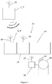
- FIG. 1 shows an example of an elevator system 1 according to the present disclosure.
- the portable emergency stop switch 2 has a housing 14 containing a signal transmitter 16.
- the signal transmitter 16 is an electronic transmitter board 16.
- a maintenance person may choose to press the portable emergency stop switch, for example when they feel uncomfortable about the situation or if they sense any danger, e.g. if they observe a loose component in the elevator system, or if the elevator car travels at a speed which they are not comfortable with.
- a maintenance person presses the button 12 this activates the portable emergency stop switch 2.
- the signal transmitter 16 then transmits a wireless, e.g. radio frequency, signal 4.
- This signal 4 is received by a signal receiver 6.
- the signal receiver 6 is an electronic circuit board 6.
- the signal receiver 6 includes an antenna 7, arranged to receive the wireless signal 4. Once the signal receiver 6 receives the signal 4, the signal receiver 6 triggers the safety actuators 8 to deploy the elevator safety brakes 10 (it will be appreciated that while two actuators 8 and two brakes 10 are shown in the figure, a single actuator 8 and brake 10 may be used, or three or more actuators 8 and brakes 10 may be used).
- the signal receiver 6 may, on receipt of the signal 4, open a switch that supplies power to the safety actuator 8.
- the safety actuator 8 may include a solenoid arranged to hold the elevator safety brake 10 in a non-engaging position as long as power is supplied to the solenoid. Thus, when the signal receiver 6 receives the signal 4 and opens the switch which supplies power to the safety actuator 8, the solenoid is dropped and the elevator safety brake 10 is deployed.
- the portable emergency stop switch 2 includes attachment means 18, which in this example is a clip.
- the attachment means 18 allows a maintenance person to affix the portable emergency stop switch 2 onto their clothing or some part of their person or outer attire e.g. to a safety harness that they are wearing. Thus the portable emergency stop switch 2 will move with them and is always within easy reach.
- FIG. 2 shows another example of an elevator system 1' according to the present disclosure.
- the portable emergency stop switch 2' includes button 12'.
- the portable emergency stop switch 2' may also include attachment means 18', such as a clip, as in the example of Figure 1 , but in this example the attachment means may be different or may be omitted as discussed below.
- attachment means 18' such as a clip, as in the example of Figure 1 , but in this example the attachment means may be different or may be omitted as discussed below.
- the portable emergency stop switch 2' is connected to the signal receiver 6' by a signalling cable 20.
- the portable emergency stop switch 2' transmits a signal 4' along the signalling cable 20 to the signal receiver 6'.
- the portable emergency stop switch 2' includes a signal transmitter 16', connected to the signalling cable 20.
- This signal transmitter 16' could be a simple switch that makes or breaks a connection so as to generate a signal on the signalling cable 20.
- the signal transmitter 16' could also be arranged to transmit a wireless signal to the signal receiver 6' as well as the signalling cable 20 being arranged to transmit a signal to the signal receiver 6'.
- This signal 4' is received by the signal receiver 6'. Once the signal receiver 6' receives the signal 4', the signal receiver 6' triggers the safety actuators 8' to deploy the elevator safety brakes 10'.
- the signal receiver 6' may, on receipt of the signal 4', open a switch that supplies power to the (or each) safety actuator 8'.
- the safety actuator 8' may include a solenoid, arranged to hold the elevator safety brake 10' in a non-engaging position as long as power is supplied to the solenoid.
- the solenoid is dropped and the elevator safety brake 10' is deployed.
- the attachment means 18' may be omitted or it may take a different form, e.g. for temporary attachment to other structures.
- a magnetic attachment could be used to keep the button 12' close to the working area, but still allowing it to be moved when the working area changes so that the button 12' is always conveniently located. It will of course be appreciated that such magnetic (or other) attachments may also be used for wireless buttons discussed in relation to Figure 1 .
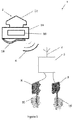
- FIG 3 shows a possible arrangement of the signal receiver 6, 6' and a second signal receiver 26, according to the present disclosure.
- the portable emergency stop switch 2, 2' in Figure 3 is shown as having an antenna 32, and likewise the first signal receiver 6, 6' has antenna 34 and the second signal receiver 26 has antenna 36, it will be understood by the skilled person that any or all of the signals described between these antennae may alternatively be transmitted by means of a signalling cable, as described in the present disclosure.
- the elevator system includes a known safety actuation board 24, as is known in the art.
- the safety actuation board 24 is connected to a speed sensor and an acceleration sensor (not shown) and is arranged to trigger at least one actuator to deploy the elevator safety brake, based on the readings of at least one of these sensors e.g. when the detected speed or acceleration exceeds a given threshold.
- the safety actuation board 24 has been altered, according to the present invention, to further include a first signal receiver 6, 6' (e.g. a first electronic receiver board) and a second signal receiver 26 (e.g. a second electronic receiver board). This provides a main safety actuation board 22 according to the present disclosure.
- the second signal receiver 26 is arranged to control a power supply to the safety actuation board 24.
- a third signal receiver 28 with antenna 29 may be arranged to control the power supply to the elevator drive system 40 and/or machine brake 42 of the elevator system.
- the second signal receiver 26 or the main safety actuation board 22 may be arranged to cut the power supply to any or all of the other electronic components which are controlled from the elevator car.
- first signal receiver 6, 6' and or the second signal receiver 26 may not be part of the main safety actuation board 22 but may be standalone components that communicate with the safety actuation board 24.
Landscapes
- Engineering & Computer Science (AREA)
- Automation & Control Theory (AREA)
- Mechanical Engineering (AREA)
- Computer Networks & Wireless Communication (AREA)
- Elevator Control (AREA)
- Indicating And Signalling Devices For Elevators (AREA)
- Maintenance And Inspection Apparatuses For Elevators (AREA)
Abstract
Description
- This disclosure relates to triggering of elevator safety brakes.
- It is known in the art to include an electronic safety board in an elevator system. The electronic safety board is arranged to receive sensor data from sensors within the elevator system e.g. speed and acceleration sensor data, to process this received sensor data and trigger safety equipment in response, when necessary.
- It is known for elevator system safety equipment to include safety gear, also referred to as "safeties". Safeties are brakes, often wedge shaped, which are arranged to be pushed into contact with an elevator guide rail in order to create friction against the guide rail, and thereby reduce the speed of the elevator car.
- It is common for the deployment of the safety gears to be caused by a mechanical stimulus, such as overspeed of the governor sheave resulting in locking of that sheave. However, there are also safeties for which the deployment is controlled by electronic means e.g. by a solenoid.
- The present disclosure seeks to provide an elevator system with improved safety.
- According to a first aspect of this disclosure there is provided an elevator system comprising:
- a portable emergency stop switch, arranged to transmit a signal when activated;
- a signal receiver, arranged to receive the signal transmitted by the portable emergency stop switch; and
- an elevator safety actuator and an elevator safety brake, wherein in response to receipt of the signal, the signal receiver is arranged to trigger the elevator safety actuator to deploy the elevator safety brake.
- According to a second aspect of the present invention, there is provided an emergency signalling system, comprising:
- a portable emergency stop switch, arranged to transmit a signal when activated; and
- a signal receiver, arranged to receive the signal transmitted by the portable emergency stop switch, wherein in response to receipt of the signal, the signal receiver is arranged to output a signal which is suitable for triggering an elevator safety actuator to deploy an elevator safety brake.
- According to a third aspect of the present invention, there is provided a method of deploying an elevator safety brake by service personnel, comprising:
- activating a portable emergency stop switch by the service personnel;
- transmitting a signal, by the portable emergency stop switch, in response to activation of the portable emergency stop switch;
- receiving the signal with a signal receiver;
- triggering of an elevator safety actuator to deploy the elevator safety brake, in response to the receipt of the signal.
- By arranging a portable emergency stop switch to trigger an elevator safety brake, when activated, the present disclosure allows service personnel to activate the safety brake whenever they feel it might be desirable. The portable emergency stop switch allows the safety brake to be triggered by a person who activates the switch, independently of any automatic triggering of safety brake deployment which occurs based on the readings of sensors, that may indicate a dangerous situation.
- This is particularly advantageous during construction of an elevator system. At such time the elevator system may not yet be fully functional, or may not be functioning properly. For example, there may be dust in the system that may adversely affect the functioning of certain sensors, or there may be certain components e.g. the guide rails, which have not yet been fully fixed in position. For reasons such as these, accidents are more frequent during this construction phase, for example test runs of the elevator system can sometimes go wrong which can risk injury or other danger, particularly for service personnel working in the elevator hoistway or within the elevator car. It is advantageous that during construction a maintenance person working on the elevator system can use their own judgement, and operate the elevator safety brakes easily using the portable emergency stop switch. For example, a maintenance person may observe that a component e.g. the guide rail, is loose, and may just deploy the elevator safety brake using the portable emergency stop switch, in order to stop the elevator car, and prevent any potential accident. In this case sensors within the elevator system may fail to detect such an issue. In another example, the elevator car may be travelling down the hoistway, not in a freefall (which would be detected and stopped by other elevator systems) but at or above the contract speed (contract speed being the speed at which the elevator car is intended or supposed to travel during normal operation). In this instance, the elevator system may not detect any immediate danger, and thus may not automatically deploy the safety brake, but nonetheless a maintenance person working on the elevator system may feel unsafe. The portable emergency stop switch according to the present disclosure allows the maintenance person in such a situation to choose to deploy the elevator safety brake. This increases safety for the maintenance person.
- According to the present disclosure the portable emergency stop switch is arranged to transmit a signal when "activated". It will be understood by the skilled person that the term "activate" covers any mechanism by which a maintenance person may create an input to the portable emergency stop switch in order to indicate their wish to deploy the safety brake.
- Optionally the portable emergency stop switch comprises a button. This is particularly advantageous since a button can be easily activated by service personnel and it is unlikely to be activated mistakenly. A button is also simple to implement and is robust in operation (unlikely to fail). The portable emergency stop switch could be any other device which is able to be activated by a maintenance person e.g. an audio sensor, a capacitive touch sensor, an emergency pull cord etc.
- Optionally the portable emergency stop switch comprises a housing, and a signal transmitter arranged within the housing, wherein the signal transmitter is arranged to transmit the signal when the portable emergency stop switch is activated. The signal transmitter may be any signal transmitter device, such as an electronic transmitter board, e.g. a printed circuit board with transmitter circuitry thereon.
- Optionally the signal is a wireless signal. This advantageously allows the portable emergency stop switch to transmit the signal from any location, so that it can be used anywhere within signal range of the signal receiver, without having to be in wired connection with the signal receiver. Thus service personnel working on the elevator system can carry the portable emergency stop switch with them whilst working, without having to ensure that a wired connection is maintained.
- In some examples, the wireless signal is a radio frequency (RF) signal. Protocols such as Bluetooth, WiFi, etc. could be used. However it may be advantageous for the signal to be simply a direct RF signal transmission, e.g. of a particular wavelength, such that it can be detected by a very simple signal receiver, e.g. with analogue electronics. In other examples, the wireless signal could be an ultrasound transmission.
- In some examples the portable emergency stop switch is wearable. This advantageously allows an easy way for service personnel to carry the portable emergency stop switch with them as they work on the elevator system, such that it will always be accessible and close to them in the event that they need to activate the portable emergency stop switch to deploy the brakes.
- In some examples, the portable emergency stop switch comprises attachment means, allowing service personnel e.g. a maintenance person to attach the portable emergency stop switch to their person, harness or clothing. For example, the portable emergency stop switch may comprise a clip and/or strap and/or harness, and/or any other suitable attachment mechanism. This advantageously provides a maintenance person with a simple mechanism by which to carry the portable emergency stop switch with them as they work, so that it is easily accessible to them at all times, should they need to activate the portable emergency stop switch to deploy the brakes.
- In some examples, the portable emergency stop switch is located, in use, in proximity to a maintenance person.
- In some examples the system comprises a signalling cable, connecting the portable emergency stop switch to the signal receiver. This signalling cable may be provided in order to facilitate the sending of the signal from the portable emergency stop switch to the signal receiver, as described above. This signalling cable could be provided instead of the signal transmitter described above. Alternatively, the signalling cable could be provided in addition to the signal transmitter. This advantageously provides a redundancy, since the signal can be sent to the signal receiver via both a wired connection i.e. the signalling cable and via a wireless connection i.e. using the signal transmitter. Further alternatively, the elevator system may comprise a first portable emergency stop switch comprising a housing, comprising a signal transmitter arranged within the housing, wherein the signal transmitter is arranged to transmit the signal when the first portable emergency stop switch is activated, and may comprise a second portable emergency stop switch, connected to the signal receiver by the signalling cable. This advantageously provides service personnel with two portable emergency stop switches, one of which signals the signal receiver using a signalling cable, and the other of which uses a signal transmitter. The service personnel may thus choose which of these portable emergency stop switches is most appropriate for use during any given task and may simply use whichever switch is most convenient in order to achieve the same goal. The use of a signal transmitter (optionally together with a signalling cable) is further advantageous in that it can broadcast a signal that can be received by multiple different signal receivers. Thus the single signal transmitter may be used to activate more than one safety system. For example it may activate separate safety actuators and/or it may activate a machine brake elsewhere in the hoistway (e.g. in a machine room).
- The signal receiver may also be arranged to shut off a power supply to the elevator system, and/or to shut off power to a machine brake, so as to deploy the machine brake.
- The elevator system may further comprise an elevator car, comprising a roof. In this example, the signal receiver may be located on the roof of the elevator car. This may be particularly advantageous in examples in which the portable emergency stop switch is connected to the signal receiver by a signalling cable. In this case the signal receiver is located on the roof of the elevator car, and thus service personnel can easily access the portable emergency stop switch when working on the roof of the elevator car. In some examples the signalling cable is at least 1 m in length, in some examples at least 2m in length, in some examples at least 5m in length. This helps to ensure that the length of the signalling cable is sufficient to allow a maintenance person working on the roof of the elevator car to keep the portable emergency stop switch close to them, or even on their person, as they work, without being restricted in their movement by the signalling cable. The length of the signalling cable is preferably also not too long, e.g. less than 10m in length, in some examples less than 5m in length, in some examples less than 3m in length. The choice of length will depend on the size of the elevator car. This helps to prevent the portable emergency stop switch from extending over the roof of the elevator car, since the length of the signalling cable is sufficiently short that the portable emergency stop switch does not reach to the edge of the roof of the elevator car.
- The signal receiver may be any signal receiver device, such as an electronic receiver board. For example the signal receiver may be a printed circuit board with receiver circuitry thereon. The receiver circuitry may comprise analogue electronics. The signal receiver may be a wireless signal receiver for receiving a wirelessly transmitted signal.
- The signal receiver may be a stand-alone component of the elevator system. Alternatively, the signal receiver may be part of a main safety actuation board of an elevator car, wherein the main safety actuation board is connected to and/or arranged to control other safety equipment of the elevator system. For example, the main safety actuation board may comprise or may be connected to a speed sensor and/or an acceleration sensor. The main safety actuation board may be arranged to deploy the elevator safety brake based on data from the speed sensor and/or the acceleration sensor. The main safety actuation board may contain capacitors arranged to trigger at least one actuator which thereby deploys the elevator safety brake. The main safety actuation board may be manufactured as a single board containing the signal receiver (e.g. in the form of an electronic receiver board). Alternatively, the signal receiver may be a separate component (e.g. a separate electronic receiver board) that is added to an existing safety actuation board of the elevator system i.e. it can be retro-fitted, so as to upgrade a main safety actuation board to operate in accordance with the present disclosure.
- In some examples the signal receiver is a first signal receiver, and the system further comprises a second signal receiver arranged to disconnect a power supply to an elevator car and/or to an elevator drive system in response to the receipt of the signal. The power supply may be a mains power supply, or may be a power supply from a separate power source, for example an independent generator or a battery. The second signal receiver may be any signal receiver device, e.g. it may be an electronic receiver board such as a printed circuit board comprising electronic receiver circuitry.
- The second signal receiver may be part of the main safety actuation board of the elevator car. Alternatively the second signal receiver may be an add-on as discussed above for upgrading an existing main safety actuation board in a retro-fit procedure.
- The second signal receiver may be separate from the elevator car, e.g. located elsewhere in the hoistway such as in a machine room. The second signal receiver may disconnect power to a drive motor and/or a machine brake that brakes the drive motor or a drive sheave. The disconnection of power will normally result in engagement of the machine brake as the design of such brakes is that power is required to hold the brake pad away from its respective braking surface.
- In other examples a further signal receiver may be provided for separate actuation of another safety device (e.g. another brake) without necessarily having to cut power. This may be useful for other safety systems that do not automatically activate upon loss of power. The further signal receiver may be any signal receiver device, such as an electronic receiver board as discussed above.
- In some examples the signal receiver (e.g. electronic receiver board) comprises at least one capacitor. The at least one capacitor may thus provide energy storage, so that the electronic receiver board is still able to trigger the elevator safety actuator to deploy the elevator safety brake, even in the event of a power failure.
- As discussed above, this method of deploying a safety brake may be applied during a construction phase of an elevator or a building. It is during this phase that accidents are most likely due to the amount of work being carried out, the harsh conditions in the environment during that work and the incomplete construction state of the system.
- Features of any aspect or example described herein may, wherever appropriate, be applied to any other aspect or example described herein. Where reference is made to different examples or sets of examples, it should be understood that these are not necessarily distinct but may overlap.
- Certain preferred examples of this disclosure will now be described, by way of example only, with reference to the accompanying drawings, in which:
-
Figure 1 is a schematic drawing showing a first example of an elevator system according to the present disclosure. -
Figure 2 is a schematic drawing showing a second example of an elevator system according to the present disclosure. -
Figure 3 is a schematic drawing showing a portable emergency stop switch, a first signal receiver and a second signal receiver, according to the present disclosure. -
Figure 1 shows an example of anelevator system 1 according to the present disclosure. The portableemergency stop switch 2 has ahousing 14 containing asignal transmitter 16. In this example, thesignal transmitter 16 is anelectronic transmitter board 16. A maintenance person may choose to press the portable emergency stop switch, for example when they feel uncomfortable about the situation or if they sense any danger, e.g. if they observe a loose component in the elevator system, or if the elevator car travels at a speed which they are not comfortable with. When a maintenance person presses thebutton 12, this activates the portableemergency stop switch 2. Thesignal transmitter 16 then transmits a wireless, e.g. radio frequency,signal 4. Thissignal 4 is received by asignal receiver 6. In the example shown in the Figures, thesignal receiver 6 is anelectronic circuit board 6. As can be seen, thesignal receiver 6 includes anantenna 7, arranged to receive thewireless signal 4. Once thesignal receiver 6 receives thesignal 4, thesignal receiver 6 triggers thesafety actuators 8 to deploy the elevator safety brakes 10 (it will be appreciated that while twoactuators 8 and twobrakes 10 are shown in the figure, asingle actuator 8 and brake 10 may be used, or three ormore actuators 8 andbrakes 10 may be used). Various techniques of deploying elevator safety brakes are known in the art. In some examples, thesignal receiver 6 may, on receipt of thesignal 4, open a switch that supplies power to thesafety actuator 8. Thesafety actuator 8 may include a solenoid arranged to hold theelevator safety brake 10 in a non-engaging position as long as power is supplied to the solenoid. Thus, when thesignal receiver 6 receives thesignal 4 and opens the switch which supplies power to thesafety actuator 8, the solenoid is dropped and theelevator safety brake 10 is deployed. - The portable
emergency stop switch 2 includes attachment means 18, which in this example is a clip. The attachment means 18 allows a maintenance person to affix the portableemergency stop switch 2 onto their clothing or some part of their person or outer attire e.g. to a safety harness that they are wearing. Thus the portableemergency stop switch 2 will move with them and is always within easy reach. -
Figure 2 shows another example of an elevator system 1' according to the present disclosure. The portable emergency stop switch 2' includes button 12'. The portable emergency stop switch 2' may also include attachment means 18', such as a clip, as in the example ofFigure 1 , but in this example the attachment means may be different or may be omitted as discussed below. When a maintenance person presses the button 12', this activates the portable emergency stop switch 2'. The portable emergency stop switch 2' is connected to the signal receiver 6' by asignalling cable 20. When a maintenance person presses the button 12', the portable emergency stop switch 2' transmits a signal 4' along the signallingcable 20 to the signal receiver 6'. The portable emergency stop switch 2' includes a signal transmitter 16', connected to thesignalling cable 20. This signal transmitter 16' could be a simple switch that makes or breaks a connection so as to generate a signal on thesignalling cable 20. Alternatively, the signal transmitter 16' could also be arranged to transmit a wireless signal to the signal receiver 6' as well as the signallingcable 20 being arranged to transmit a signal to the signal receiver 6'. This signal 4' is received by the signal receiver 6'. Once the signal receiver 6' receives the signal 4', the signal receiver 6' triggers the safety actuators 8' to deploy the elevator safety brakes 10'. Various techniques of deploying elevator safety brakes are known in the art. In some examples, the signal receiver 6' may, on receipt of the signal 4', open a switch that supplies power to the (or each) safety actuator 8'. The safety actuator 8' may include a solenoid, arranged to hold the elevator safety brake 10' in a non-engaging position as long as power is supplied to the solenoid. Thus, when the signal receiver 6' receives the signal 4' and opens the switch which supplies power to the safety actuator 8', the solenoid is dropped and the elevator safety brake 10' is deployed. In this example, as the button 12' is on the end of asignalling cable 20, it may be preferred not to attach the button 12' to the clothing or harness of the maintenance personnel. Therefore, the attachment means 18' may be omitted or it may take a different form, e.g. for temporary attachment to other structures. For example a magnetic attachment could be used to keep the button 12' close to the working area, but still allowing it to be moved when the working area changes so that the button 12' is always conveniently located. It will of course be appreciated that such magnetic (or other) attachments may also be used for wireless buttons discussed in relation toFigure 1 . -
Figure 3 shows a possible arrangement of thesignal receiver 6, 6' and asecond signal receiver 26, according to the present disclosure. Although the portableemergency stop switch 2, 2' inFigure 3 is shown as having anantenna 32, and likewise thefirst signal receiver 6, 6' hasantenna 34 and thesecond signal receiver 26 hasantenna 36, it will be understood by the skilled person that any or all of the signals described between these antennae may alternatively be transmitted by means of a signalling cable, as described in the present disclosure. - The elevator system includes a known
safety actuation board 24, as is known in the art. Thesafety actuation board 24 is connected to a speed sensor and an acceleration sensor (not shown) and is arranged to trigger at least one actuator to deploy the elevator safety brake, based on the readings of at least one of these sensors e.g. when the detected speed or acceleration exceeds a given threshold. Thesafety actuation board 24 has been altered, according to the present invention, to further include afirst signal receiver 6, 6' (e.g. a first electronic receiver board) and a second signal receiver 26 (e.g. a second electronic receiver board). This provides a mainsafety actuation board 22 according to the present disclosure. - The
second signal receiver 26 is arranged to control a power supply to thesafety actuation board 24. Alternatively, or additionally, athird signal receiver 28 withantenna 29 may be arranged to control the power supply to theelevator drive system 40 and/ormachine brake 42 of the elevator system. - If the
second signal receiver 26 or the mainsafety actuation board 22 is located on the elevator car, thesecond signal receiver 26 may be arranged to cut the power supply to any or all of the other electronic components which are controlled from the elevator car. - In an alternative, not shown in
Figure 3 , thefirst signal receiver 6, 6' and or thesecond signal receiver 26 may not be part of the mainsafety actuation board 22 but may be standalone components that communicate with thesafety actuation board 24. - It will be appreciated by those skilled in the art that the invention has been illustrated by describing one or more specific embodiments thereof, but is not limited to these embodiments; many variations and modifications are possible, within the scope of the accompanying claims.
Claims (15)
- An elevator system (1, 1') comprising:a portable emergency stop switch (2, 2'), arranged to transmit a signal (4) when activated;a signal receiver (6, 6'), arranged to receive the signal (4, 4') transmitted by the portable emergency stop switch (2, 2'); andan elevator safety actuator (8, 8') and an elevator safety brake (10, 10'), wherein in response to receipt of the signal (4, 4'), the signal receiver (6, 6') is arranged to trigger the elevator safety actuator (8, 8') to deploy the elevator safety brake (10, 10').
- An elevator system (1, 1') as claimed in claim 1, wherein the portable emergency stop switch (2, 2') comprises a button (12, 12').
- An elevator system (1) as claimed in claim 1 or 2 wherein the portable emergency stop switch (2, 2') comprises a housing (14), and a signal transmitter (16, 16') arranged within the housing (14), wherein the signal transmitter (16) is arranged to transmit the signal (4, 4') when the portable emergency stop switch (2, 2') is activated.
- An elevator system (1) as claimed in any preceding claim, wherein the signal (4) is a wireless signal.
- An elevator system (1, 1') as claimed in any preceding claim, wherein the portable emergency stop switch (2, 2') is wearable.
- An elevator system (1, 1') as claimed in any preceding claim, wherein the portable emergency stop switch (2, 2') comprises attachment means (18, 18'), allowing a maintenance person to attach the portable emergency stop switch (2, 2') to their person or clothing or harness.
- An elevator system (1') as claimed in any preceding claim, wherein the system further comprises a signalling cable (20), connecting the portable emergency stop switch (2') to the signal receiver (6').
- An elevator system (1') as claimed in claim 7, further comprising an elevator car, wherein the signal receiver (6') is located on the roof of the elevator car.
- An elevator system (1') as claimed in claim 8, wherein the signalling cable (20) is at least 1m in length, optionally at least 2m in length, optionally at least 5m in length.
- An elevator system (1, 1') as claimed in any preceding claim, wherein the signal receiver (6, 6') is part of a main safety actuation board (22) of an elevator car, wherein the main safety actuation board (22) is arranged to control other safety equipment of the elevator system.
- An elevator system (1, 1') as claimed in any preceding claim, wherein the signal receiver (6, 6') is a first signal receiver, and wherein the system further comprises a second signal receiver (26) arranged to disconnect a power supply to an elevator car and/or to an elevator drive system in response to the receipt of the signal (4, 4').
- An elevator system (1, 1') as claimed in claim 11, wherein the second signal receiver (26) is arranged to disconnect a power supply in a machine room of the elevator system.
- An emergency signalling system, comprising:a portable emergency stop switch (2, 2'), arranged to transmit a signal (4, 4') when activated; anda signal receiver (6, 6'), arranged to receive the signal (4, 4') transmitted by the portable emergency stop switch (2, 2'), wherein in response to receipt of the signal (4, 4'), the signal receiver (6, 6') is arranged to output a signal (4, 4') which is suitable for triggering an elevator safety actuator (8, 8') to deploy an elevator safety brake (10, 10').
- A method of deploying an elevator safety brake (10, 10') by service personnel, comprising:activating a portable emergency stop switch (2, 2') by the service personnel;transmitting a signal (4, 4'), by the portable emergency stop switch (2, 2'), in response to activation of the portable emergency stop switch (2, 2');receiving the signal (4, 4') with a signal receiver (6, 6');triggering of an elevator safety actuator (8, 8') to deploy the elevator safety brake (10, 10'), in response to the receipt of the signal (4, 4').
- A method as claimed in claim 14, wherein the safety brake (10, 10') is deployed during a construction phase of the elevator system.
Priority Applications (3)
| Application Number | Priority Date | Filing Date | Title |
|---|---|---|---|
| EP19383041.1A EP3828117B1 (en) | 2019-11-26 | 2019-11-26 | Safety brake trigger |
| US16/951,679 US12486140B2 (en) | 2019-11-26 | 2020-11-18 | Safety brake trigger |
| CN202011349698.XA CN112938687B (en) | 2019-11-26 | 2020-11-26 | Elevator system, emergency signaling system and method for deploying elevator safety brake |
Applications Claiming Priority (1)
| Application Number | Priority Date | Filing Date | Title |
|---|---|---|---|
| EP19383041.1A EP3828117B1 (en) | 2019-11-26 | 2019-11-26 | Safety brake trigger |
Publications (2)
| Publication Number | Publication Date |
|---|---|
| EP3828117A1 true EP3828117A1 (en) | 2021-06-02 |
| EP3828117B1 EP3828117B1 (en) | 2024-02-14 |
Family
ID=68808241
Family Applications (1)
| Application Number | Title | Priority Date | Filing Date |
|---|---|---|---|
| EP19383041.1A Active EP3828117B1 (en) | 2019-11-26 | 2019-11-26 | Safety brake trigger |
Country Status (3)
| Country | Link |
|---|---|
| US (1) | US12486140B2 (en) |
| EP (1) | EP3828117B1 (en) |
| CN (1) | CN112938687B (en) |
Families Citing this family (2)
| Publication number | Priority date | Publication date | Assignee | Title |
|---|---|---|---|---|
| EP3459890B1 (en) * | 2017-09-20 | 2024-04-03 | Otis Elevator Company | Health monitoring of safety braking systems for elevators |
| EP3828117B1 (en) * | 2019-11-26 | 2024-02-14 | Otis Elevator Company | Safety brake trigger |
Citations (2)
| Publication number | Priority date | Publication date | Assignee | Title |
|---|---|---|---|---|
| JP2011162275A (en) * | 2010-02-04 | 2011-08-25 | Toshiba Elevator Co Ltd | Emergency stopping device of elevator |
| US20170355559A1 (en) * | 2014-12-18 | 2017-12-14 | Inventio Ag | Method for operating an electronic safety system with temporary participants |
Family Cites Families (31)
| Publication number | Priority date | Publication date | Assignee | Title |
|---|---|---|---|---|
| US4304375A (en) * | 1979-05-17 | 1981-12-08 | Textron Inc. | Electrically controlled elevator |
| US5893432A (en) * | 1996-12-31 | 1999-04-13 | Inventio Ag | Controlled emergency stop apparatus for elevators |
| EP1514831B1 (en) * | 2003-09-15 | 2015-12-09 | Inventio AG | Sealing arrangement for elevator with an electromagneticallly retractable door wing seal |
| BRPI0318536B1 (en) * | 2003-10-07 | 2015-10-13 | Otis Elevator Co | electric lift rescue system |
| US7434664B2 (en) * | 2005-03-08 | 2008-10-14 | Kone Corporation | Elevator brake system method and control |
| ES2499340T3 (en) * | 2007-08-07 | 2014-09-29 | Thyssenkrupp Elevator Ag | Elevator system |
| CN201873398U (en) * | 2010-11-10 | 2011-06-22 | 日立电梯(上海)有限公司 | Hand-held multifunction car roof control device |
| FI123348B (en) * | 2011-10-07 | 2013-02-28 | Kone Corp | Elevator control arrangement and method of elevator control |
| US20130098712A1 (en) * | 2011-10-21 | 2013-04-25 | S.R. Smith, Llc | Control for lift for pool |
| FI123506B (en) * | 2012-05-31 | 2013-06-14 | Kone Corp | Elevator control and elevator safety arrangement |
| JP2014234292A (en) * | 2013-06-05 | 2014-12-15 | 株式会社日立製作所 | Elevator system |
| MX370155B (en) * | 2013-08-09 | 2019-12-04 | Inventio Ag | Communication method for a lift system. |
| JP6177629B2 (en) * | 2013-08-30 | 2017-08-09 | 株式会社日立製作所 | Electronic safety elevator |
| FI125316B (en) * | 2013-09-10 | 2015-08-31 | Kone Corp | Procedure for performing emergency stops and safety arrangements for lifts |
| ES3029875T3 (en) * | 2014-09-12 | 2025-06-25 | Otis Elevator Co | Elevator brake control system |
| CN104444672A (en) * | 2014-10-10 | 2015-03-25 | 上海大学 | Elevator braking performance detection system |
| WO2016096826A1 (en) * | 2014-12-18 | 2016-06-23 | Inventio Ag | Method for operating an electronic safety system with temporary subscribers |
| BR112017010993A2 (en) * | 2014-12-18 | 2017-12-26 | Inventio Ag | process for operating an electronic security system with temporary subscribers |
| FI125887B (en) * | 2015-01-16 | 2016-03-31 | Kone Corp | Elevator rescue device |
| CN205087728U (en) * | 2015-09-30 | 2016-03-16 | 广州市特威工程机械有限公司 | Lift wireless control system |
| CN106744095A (en) * | 2017-01-11 | 2017-05-31 | 菱王电梯股份有限公司 | Hand-held type multifunctional intelligent operation apparatus |
| EP3599203B1 (en) * | 2018-07-27 | 2022-06-15 | Otis Elevator Company | Elevator safety system |
| CN109353910B (en) * | 2018-12-28 | 2021-06-08 | 住友富士电梯有限公司 | A car wireless detection device and elevator |
| CN209507350U (en) * | 2019-01-21 | 2019-10-18 | 上海天逸电器有限公司 | A kind of both hands operation maintenance box device |
| CN110526052B (en) * | 2019-09-12 | 2024-03-15 | 上海和兰透平动力技术有限公司 | Actuator control system |
| EP3828117B1 (en) * | 2019-11-26 | 2024-02-14 | Otis Elevator Company | Safety brake trigger |
| US12157657B2 (en) * | 2019-11-28 | 2024-12-03 | Otis Elevator Company | Emergency stop system for elevator |
| CN210639734U (en) * | 2019-12-12 | 2020-05-29 | 陈佩金 | Wearable wireless emergency button alarm device for prison police |
| US20220033215A1 (en) * | 2020-08-01 | 2022-02-03 | Otis Elevator Company | Elevator motion control after electrical protective device activation |
| WO2022059096A1 (en) * | 2020-09-16 | 2022-03-24 | 三菱電機ビルテクノサービス株式会社 | Emergency communication system for elevator |
| ES2978540T3 (en) * | 2020-10-07 | 2024-09-13 | Otis Elevator Co | Safety brake device |
-
2019
- 2019-11-26 EP EP19383041.1A patent/EP3828117B1/en active Active
-
2020
- 2020-11-18 US US16/951,679 patent/US12486140B2/en active Active
- 2020-11-26 CN CN202011349698.XA patent/CN112938687B/en active Active
Patent Citations (2)
| Publication number | Priority date | Publication date | Assignee | Title |
|---|---|---|---|---|
| JP2011162275A (en) * | 2010-02-04 | 2011-08-25 | Toshiba Elevator Co Ltd | Emergency stopping device of elevator |
| US20170355559A1 (en) * | 2014-12-18 | 2017-12-14 | Inventio Ag | Method for operating an electronic safety system with temporary participants |
Also Published As
| Publication number | Publication date |
|---|---|
| CN112938687B (en) | 2022-09-27 |
| US20210155447A1 (en) | 2021-05-27 |
| EP3828117B1 (en) | 2024-02-14 |
| CN112938687A (en) | 2021-06-11 |
| US12486140B2 (en) | 2025-12-02 |
Similar Documents
| Publication | Publication Date | Title |
|---|---|---|
| US12486140B2 (en) | Safety brake trigger | |
| CN103261073B (en) | Elevator installation with car and counterweight | |
| US7893645B2 (en) | System and method for compartment control | |
| US7887008B2 (en) | System and method for a power-assisted compartment | |
| US8494663B2 (en) | System and method for an electronic interactive switch | |
| US7723935B2 (en) | System and method for compartment control | |
| US20080078871A1 (en) | System and method for electronically latching compartments | |
| US9567193B2 (en) | Method for controlling a load-moving device and controller of a load-moving device | |
| US7434664B2 (en) | Elevator brake system method and control | |
| US20080071398A1 (en) | System and method for compartment control | |
| US10252884B2 (en) | Wirelessly powered elevator electronic safety device | |
| EP3135620B1 (en) | Elevator | |
| TR200102329T2 (en) | Device to prevent uncontrolled acceleration of an elevator car mounted on an elevator assembly. | |
| CN106976770B (en) | Service alarm device for elevator system | |
| KR101138387B1 (en) | Elevator control system by wireless communication | |
| WO2005117539B1 (en) | Method and arrangement for stopping powered equipment in an emergency situation | |
| CN115849132B (en) | Elevator brake release devices and systems | |
| US20210122610A1 (en) | Maintenance control panel and elevator control system for controlling displacement movements of an elevator car | |
| EP4400466B1 (en) | Emergency stop system for elevator | |
| KR101874713B1 (en) | Safety belt system capable of automatic unlocking | |
| US6538574B2 (en) | Device for signaling the position of an elevator car in the case of passenger evacuation | |
| EP1980489A2 (en) | Aircraft security | |
| JPH11165981A (en) | Wireless control device for crane | |
| EP1151954B1 (en) | Device for signalizing the position of an elevator car in the case of passenger evacuation | |
| EP1902922B1 (en) | Sectional support |
Legal Events
| Date | Code | Title | Description |
|---|---|---|---|
| PUAI | Public reference made under article 153(3) epc to a published international application that has entered the european phase |
Free format text: ORIGINAL CODE: 0009012 |
|
| STAA | Information on the status of an ep patent application or granted ep patent |
Free format text: STATUS: THE APPLICATION HAS BEEN PUBLISHED |
|
| AK | Designated contracting states |
Kind code of ref document: A1 Designated state(s): AL AT BE BG CH CY CZ DE DK EE ES FI FR GB GR HR HU IE IS IT LI LT LU LV MC MK MT NL NO PL PT RO RS SE SI SK SM TR |
|
| STAA | Information on the status of an ep patent application or granted ep patent |
Free format text: STATUS: REQUEST FOR EXAMINATION WAS MADE |
|
| 17P | Request for examination filed |
Effective date: 20211202 |
|
| RBV | Designated contracting states (corrected) |
Designated state(s): AL AT BE BG CH CY CZ DE DK EE ES FI FR GB GR HR HU IE IS IT LI LT LU LV MC MK MT NL NO PL PT RO RS SE SI SK SM TR |
|
| GRAP | Despatch of communication of intention to grant a patent |
Free format text: ORIGINAL CODE: EPIDOSNIGR1 |
|
| STAA | Information on the status of an ep patent application or granted ep patent |
Free format text: STATUS: GRANT OF PATENT IS INTENDED |
|
| INTG | Intention to grant announced |
Effective date: 20231010 |
|
| GRAS | Grant fee paid |
Free format text: ORIGINAL CODE: EPIDOSNIGR3 |
|
| GRAA | (expected) grant |
Free format text: ORIGINAL CODE: 0009210 |
|
| STAA | Information on the status of an ep patent application or granted ep patent |
Free format text: STATUS: THE PATENT HAS BEEN GRANTED |
|
| AK | Designated contracting states |
Kind code of ref document: B1 Designated state(s): AL AT BE BG CH CY CZ DE DK EE ES FI FR GB GR HR HU IE IS IT LI LT LU LV MC MK MT NL NO PL PT RO RS SE SI SK SM TR |
|
| REG | Reference to a national code |
Ref country code: GB Ref legal event code: FG4D |
|
| REG | Reference to a national code |
Ref country code: CH Ref legal event code: EP |
|
| REG | Reference to a national code |
Ref country code: DE Ref legal event code: R096 Ref document number: 602019046450 Country of ref document: DE |
|
| REG | Reference to a national code |
Ref country code: IE Ref legal event code: FG4D |
|
| REG | Reference to a national code |
Ref country code: LT Ref legal event code: MG9D |
|
| REG | Reference to a national code |
Ref country code: NL Ref legal event code: MP Effective date: 20240214 |
|
| PG25 | Lapsed in a contracting state [announced via postgrant information from national office to epo] |
Ref country code: IS Free format text: LAPSE BECAUSE OF FAILURE TO SUBMIT A TRANSLATION OF THE DESCRIPTION OR TO PAY THE FEE WITHIN THE PRESCRIBED TIME-LIMIT Effective date: 20240614 |
|
| PG25 | Lapsed in a contracting state [announced via postgrant information from national office to epo] |
Ref country code: LT Free format text: LAPSE BECAUSE OF FAILURE TO SUBMIT A TRANSLATION OF THE DESCRIPTION OR TO PAY THE FEE WITHIN THE PRESCRIBED TIME-LIMIT Effective date: 20240214 |
|
| PG25 | Lapsed in a contracting state [announced via postgrant information from national office to epo] |
Ref country code: GR Free format text: LAPSE BECAUSE OF FAILURE TO SUBMIT A TRANSLATION OF THE DESCRIPTION OR TO PAY THE FEE WITHIN THE PRESCRIBED TIME-LIMIT Effective date: 20240515 |
|
| REG | Reference to a national code |
Ref country code: AT Ref legal event code: MK05 Ref document number: 1656899 Country of ref document: AT Kind code of ref document: T Effective date: 20240214 |
|
| PG25 | Lapsed in a contracting state [announced via postgrant information from national office to epo] |
Ref country code: HR Free format text: LAPSE BECAUSE OF FAILURE TO SUBMIT A TRANSLATION OF THE DESCRIPTION OR TO PAY THE FEE WITHIN THE PRESCRIBED TIME-LIMIT Effective date: 20240214 Ref country code: RS Free format text: LAPSE BECAUSE OF FAILURE TO SUBMIT A TRANSLATION OF THE DESCRIPTION OR TO PAY THE FEE WITHIN THE PRESCRIBED TIME-LIMIT Effective date: 20240514 Ref country code: NL Free format text: LAPSE BECAUSE OF FAILURE TO SUBMIT A TRANSLATION OF THE DESCRIPTION OR TO PAY THE FEE WITHIN THE PRESCRIBED TIME-LIMIT Effective date: 20240214 |
|
| PG25 | Lapsed in a contracting state [announced via postgrant information from national office to epo] |
Ref country code: ES Free format text: LAPSE BECAUSE OF FAILURE TO SUBMIT A TRANSLATION OF THE DESCRIPTION OR TO PAY THE FEE WITHIN THE PRESCRIBED TIME-LIMIT Effective date: 20240214 |
|
| PG25 | Lapsed in a contracting state [announced via postgrant information from national office to epo] |
Ref country code: AT Free format text: LAPSE BECAUSE OF FAILURE TO SUBMIT A TRANSLATION OF THE DESCRIPTION OR TO PAY THE FEE WITHIN THE PRESCRIBED TIME-LIMIT Effective date: 20240214 |
|
| PG25 | Lapsed in a contracting state [announced via postgrant information from national office to epo] |
Ref country code: RS Free format text: LAPSE BECAUSE OF FAILURE TO SUBMIT A TRANSLATION OF THE DESCRIPTION OR TO PAY THE FEE WITHIN THE PRESCRIBED TIME-LIMIT Effective date: 20240514 Ref country code: NO Free format text: LAPSE BECAUSE OF FAILURE TO SUBMIT A TRANSLATION OF THE DESCRIPTION OR TO PAY THE FEE WITHIN THE PRESCRIBED TIME-LIMIT Effective date: 20240514 Ref country code: NL Free format text: LAPSE BECAUSE OF FAILURE TO SUBMIT A TRANSLATION OF THE DESCRIPTION OR TO PAY THE FEE WITHIN THE PRESCRIBED TIME-LIMIT Effective date: 20240214 Ref country code: LT Free format text: LAPSE BECAUSE OF FAILURE TO SUBMIT A TRANSLATION OF THE DESCRIPTION OR TO PAY THE FEE WITHIN THE PRESCRIBED TIME-LIMIT Effective date: 20240214 Ref country code: IS Free format text: LAPSE BECAUSE OF FAILURE TO SUBMIT A TRANSLATION OF THE DESCRIPTION OR TO PAY THE FEE WITHIN THE PRESCRIBED TIME-LIMIT Effective date: 20240614 Ref country code: HR Free format text: LAPSE BECAUSE OF FAILURE TO SUBMIT A TRANSLATION OF THE DESCRIPTION OR TO PAY THE FEE WITHIN THE PRESCRIBED TIME-LIMIT Effective date: 20240214 Ref country code: GR Free format text: LAPSE BECAUSE OF FAILURE TO SUBMIT A TRANSLATION OF THE DESCRIPTION OR TO PAY THE FEE WITHIN THE PRESCRIBED TIME-LIMIT Effective date: 20240515 Ref country code: FI Free format text: LAPSE BECAUSE OF FAILURE TO SUBMIT A TRANSLATION OF THE DESCRIPTION OR TO PAY THE FEE WITHIN THE PRESCRIBED TIME-LIMIT Effective date: 20240214 Ref country code: ES Free format text: LAPSE BECAUSE OF FAILURE TO SUBMIT A TRANSLATION OF THE DESCRIPTION OR TO PAY THE FEE WITHIN THE PRESCRIBED TIME-LIMIT Effective date: 20240214 Ref country code: BG Free format text: LAPSE BECAUSE OF FAILURE TO SUBMIT A TRANSLATION OF THE DESCRIPTION OR TO PAY THE FEE WITHIN THE PRESCRIBED TIME-LIMIT Effective date: 20240214 Ref country code: AT Free format text: LAPSE BECAUSE OF FAILURE TO SUBMIT A TRANSLATION OF THE DESCRIPTION OR TO PAY THE FEE WITHIN THE PRESCRIBED TIME-LIMIT Effective date: 20240214 |
|
| PG25 | Lapsed in a contracting state [announced via postgrant information from national office to epo] |
Ref country code: PL Free format text: LAPSE BECAUSE OF FAILURE TO SUBMIT A TRANSLATION OF THE DESCRIPTION OR TO PAY THE FEE WITHIN THE PRESCRIBED TIME-LIMIT Effective date: 20240214 Ref country code: PT Free format text: LAPSE BECAUSE OF FAILURE TO SUBMIT A TRANSLATION OF THE DESCRIPTION OR TO PAY THE FEE WITHIN THE PRESCRIBED TIME-LIMIT Effective date: 20240614 |
|
| PG25 | Lapsed in a contracting state [announced via postgrant information from national office to epo] |
Ref country code: SE Free format text: LAPSE BECAUSE OF FAILURE TO SUBMIT A TRANSLATION OF THE DESCRIPTION OR TO PAY THE FEE WITHIN THE PRESCRIBED TIME-LIMIT Effective date: 20240214 Ref country code: PT Free format text: LAPSE BECAUSE OF FAILURE TO SUBMIT A TRANSLATION OF THE DESCRIPTION OR TO PAY THE FEE WITHIN THE PRESCRIBED TIME-LIMIT Effective date: 20240614 Ref country code: PL Free format text: LAPSE BECAUSE OF FAILURE TO SUBMIT A TRANSLATION OF THE DESCRIPTION OR TO PAY THE FEE WITHIN THE PRESCRIBED TIME-LIMIT Effective date: 20240214 Ref country code: LV Free format text: LAPSE BECAUSE OF FAILURE TO SUBMIT A TRANSLATION OF THE DESCRIPTION OR TO PAY THE FEE WITHIN THE PRESCRIBED TIME-LIMIT Effective date: 20240214 |
|
| PG25 | Lapsed in a contracting state [announced via postgrant information from national office to epo] |
Ref country code: DK Free format text: LAPSE BECAUSE OF FAILURE TO SUBMIT A TRANSLATION OF THE DESCRIPTION OR TO PAY THE FEE WITHIN THE PRESCRIBED TIME-LIMIT Effective date: 20240214 |
|
| PG25 | Lapsed in a contracting state [announced via postgrant information from national office to epo] |
Ref country code: SM Free format text: LAPSE BECAUSE OF FAILURE TO SUBMIT A TRANSLATION OF THE DESCRIPTION OR TO PAY THE FEE WITHIN THE PRESCRIBED TIME-LIMIT Effective date: 20240214 |
|
| PG25 | Lapsed in a contracting state [announced via postgrant information from national office to epo] |
Ref country code: CZ Free format text: LAPSE BECAUSE OF FAILURE TO SUBMIT A TRANSLATION OF THE DESCRIPTION OR TO PAY THE FEE WITHIN THE PRESCRIBED TIME-LIMIT Effective date: 20240214 Ref country code: EE Free format text: LAPSE BECAUSE OF FAILURE TO SUBMIT A TRANSLATION OF THE DESCRIPTION OR TO PAY THE FEE WITHIN THE PRESCRIBED TIME-LIMIT Effective date: 20240214 |
|
| PG25 | Lapsed in a contracting state [announced via postgrant information from national office to epo] |
Ref country code: SK Free format text: LAPSE BECAUSE OF FAILURE TO SUBMIT A TRANSLATION OF THE DESCRIPTION OR TO PAY THE FEE WITHIN THE PRESCRIBED TIME-LIMIT Effective date: 20240214 |
|
| PG25 | Lapsed in a contracting state [announced via postgrant information from national office to epo] |
Ref country code: SM Free format text: LAPSE BECAUSE OF FAILURE TO SUBMIT A TRANSLATION OF THE DESCRIPTION OR TO PAY THE FEE WITHIN THE PRESCRIBED TIME-LIMIT Effective date: 20240214 Ref country code: SK Free format text: LAPSE BECAUSE OF FAILURE TO SUBMIT A TRANSLATION OF THE DESCRIPTION OR TO PAY THE FEE WITHIN THE PRESCRIBED TIME-LIMIT Effective date: 20240214 Ref country code: RO Free format text: LAPSE BECAUSE OF FAILURE TO SUBMIT A TRANSLATION OF THE DESCRIPTION OR TO PAY THE FEE WITHIN THE PRESCRIBED TIME-LIMIT Effective date: 20240214 Ref country code: EE Free format text: LAPSE BECAUSE OF FAILURE TO SUBMIT A TRANSLATION OF THE DESCRIPTION OR TO PAY THE FEE WITHIN THE PRESCRIBED TIME-LIMIT Effective date: 20240214 Ref country code: DK Free format text: LAPSE BECAUSE OF FAILURE TO SUBMIT A TRANSLATION OF THE DESCRIPTION OR TO PAY THE FEE WITHIN THE PRESCRIBED TIME-LIMIT Effective date: 20240214 Ref country code: CZ Free format text: LAPSE BECAUSE OF FAILURE TO SUBMIT A TRANSLATION OF THE DESCRIPTION OR TO PAY THE FEE WITHIN THE PRESCRIBED TIME-LIMIT Effective date: 20240214 |
|
| REG | Reference to a national code |
Ref country code: DE Ref legal event code: R097 Ref document number: 602019046450 Country of ref document: DE |
|
| PG25 | Lapsed in a contracting state [announced via postgrant information from national office to epo] |
Ref country code: IT Free format text: LAPSE BECAUSE OF FAILURE TO SUBMIT A TRANSLATION OF THE DESCRIPTION OR TO PAY THE FEE WITHIN THE PRESCRIBED TIME-LIMIT Effective date: 20240214 |
|
| PLBE | No opposition filed within time limit |
Free format text: ORIGINAL CODE: 0009261 |
|
| STAA | Information on the status of an ep patent application or granted ep patent |
Free format text: STATUS: NO OPPOSITION FILED WITHIN TIME LIMIT |
|
| PG25 | Lapsed in a contracting state [announced via postgrant information from national office to epo] |
Ref country code: IT Free format text: LAPSE BECAUSE OF FAILURE TO SUBMIT A TRANSLATION OF THE DESCRIPTION OR TO PAY THE FEE WITHIN THE PRESCRIBED TIME-LIMIT Effective date: 20240214 |
|
| 26N | No opposition filed |
Effective date: 20241115 |
|
| PG25 | Lapsed in a contracting state [announced via postgrant information from national office to epo] |
Ref country code: SI Free format text: LAPSE BECAUSE OF FAILURE TO SUBMIT A TRANSLATION OF THE DESCRIPTION OR TO PAY THE FEE WITHIN THE PRESCRIBED TIME-LIMIT Effective date: 20240214 |
|
| REG | Reference to a national code |
Ref country code: CH Ref legal event code: PL |
|
| PG25 | Lapsed in a contracting state [announced via postgrant information from national office to epo] |
Ref country code: MC Free format text: LAPSE BECAUSE OF FAILURE TO SUBMIT A TRANSLATION OF THE DESCRIPTION OR TO PAY THE FEE WITHIN THE PRESCRIBED TIME-LIMIT Effective date: 20240214 |
|
| PG25 | Lapsed in a contracting state [announced via postgrant information from national office to epo] |
Ref country code: LU Free format text: LAPSE BECAUSE OF NON-PAYMENT OF DUE FEES Effective date: 20241126 |
|
| REG | Reference to a national code |
Ref country code: CH Ref legal event code: PL |
|
| GBPC | Gb: european patent ceased through non-payment of renewal fee |
Effective date: 20241126 |
|
| PG25 | Lapsed in a contracting state [announced via postgrant information from national office to epo] |
Ref country code: CH Free format text: LAPSE BECAUSE OF NON-PAYMENT OF DUE FEES Effective date: 20241130 |
|
| REG | Reference to a national code |
Ref country code: BE Ref legal event code: MM Effective date: 20241130 |
|
| PG25 | Lapsed in a contracting state [announced via postgrant information from national office to epo] |
Ref country code: GB Free format text: LAPSE BECAUSE OF NON-PAYMENT OF DUE FEES Effective date: 20241126 Ref country code: BE Free format text: LAPSE BECAUSE OF NON-PAYMENT OF DUE FEES Effective date: 20241130 |
|
| PG25 | Lapsed in a contracting state [announced via postgrant information from national office to epo] |
Ref country code: IE Free format text: LAPSE BECAUSE OF NON-PAYMENT OF DUE FEES Effective date: 20241126 |
|
| PGFP | Annual fee paid to national office [announced via postgrant information from national office to epo] |
Ref country code: DE Payment date: 20251022 Year of fee payment: 7 |
|
| PGFP | Annual fee paid to national office [announced via postgrant information from national office to epo] |
Ref country code: FR Payment date: 20251022 Year of fee payment: 7 |
|
| PG25 | Lapsed in a contracting state [announced via postgrant information from national office to epo] |
Ref country code: HU Free format text: LAPSE BECAUSE OF FAILURE TO SUBMIT A TRANSLATION OF THE DESCRIPTION OR TO PAY THE FEE WITHIN THE PRESCRIBED TIME-LIMIT; INVALID AB INITIO Effective date: 20191126 |
|
| PG25 | Lapsed in a contracting state [announced via postgrant information from national office to epo] |
Ref country code: CY Free format text: LAPSE BECAUSE OF FAILURE TO SUBMIT A TRANSLATION OF THE DESCRIPTION OR TO PAY THE FEE WITHIN THE PRESCRIBED TIME-LIMIT; INVALID AB INITIO Effective date: 20191126 |