EP3828092A1 - A packaging device and method - Google Patents
A packaging device and method Download PDFInfo
- Publication number
- EP3828092A1 EP3828092A1 EP19212509.4A EP19212509A EP3828092A1 EP 3828092 A1 EP3828092 A1 EP 3828092A1 EP 19212509 A EP19212509 A EP 19212509A EP 3828092 A1 EP3828092 A1 EP 3828092A1
- Authority
- EP
- European Patent Office
- Prior art keywords
- packaging
- cover
- body layers
- body layer
- cut section
- Prior art date
- Legal status (The legal status is an assumption and is not a legal conclusion. Google has not performed a legal analysis and makes no representation as to the accuracy of the status listed.)
- Granted
Links
Images




Classifications
-
- B—PERFORMING OPERATIONS; TRANSPORTING
- B65—CONVEYING; PACKING; STORING; HANDLING THIN OR FILAMENTARY MATERIAL
- B65D—CONTAINERS FOR STORAGE OR TRANSPORT OF ARTICLES OR MATERIALS, e.g. BAGS, BARRELS, BOTTLES, BOXES, CANS, CARTONS, CRATES, DRUMS, JARS, TANKS, HOPPERS, FORWARDING CONTAINERS; ACCESSORIES, CLOSURES, OR FITTINGS THEREFOR; PACKAGING ELEMENTS; PACKAGES
- B65D5/00—Rigid or semi-rigid containers of polygonal cross-section, e.g. boxes, cartons or trays, formed by folding or erecting one or more blanks made of paper
- B65D5/42—Details of containers or of foldable or erectable container blanks
- B65D5/44—Integral, inserted or attached portions forming internal or external fittings
- B65D5/50—Internal supporting or protecting elements for contents
- B65D5/5002—Integral elements for containers having tubular body walls
- B65D5/5007—Integral elements for containers having tubular body walls formed by inwardly protruding of folded parts of the body
-
- B—PERFORMING OPERATIONS; TRANSPORTING
- B65—CONVEYING; PACKING; STORING; HANDLING THIN OR FILAMENTARY MATERIAL
- B65D—CONTAINERS FOR STORAGE OR TRANSPORT OF ARTICLES OR MATERIALS, e.g. BAGS, BARRELS, BOTTLES, BOXES, CANS, CARTONS, CRATES, DRUMS, JARS, TANKS, HOPPERS, FORWARDING CONTAINERS; ACCESSORIES, CLOSURES, OR FITTINGS THEREFOR; PACKAGING ELEMENTS; PACKAGES
- B65D75/00—Packages comprising articles or materials partially or wholly enclosed in strips, sheets, blanks, tubes or webs of flexible sheet material, e.g. in folded wrappers
- B65D75/04—Articles or materials wholly enclosed in single sheets or wrapper blanks
- B65D75/14—Articles or materials wholly enclosed in single sheets or wrapper blanks in sheets or blanks folded-up around all sides of the contents from a portion on which the contents are placed
-
- A—HUMAN NECESSITIES
- A45—HAND OR TRAVELLING ARTICLES
- A45D—HAIRDRESSING OR SHAVING EQUIPMENT; EQUIPMENT FOR COSMETICS OR COSMETIC TREATMENTS, e.g. FOR MANICURING OR PEDICURING
- A45D27/00—Shaving accessories
- A45D27/22—Containers or carriers for storing shaving appliances
- A45D27/29—Stands for shavers or razors
-
- B—PERFORMING OPERATIONS; TRANSPORTING
- B26—HAND CUTTING TOOLS; CUTTING; SEVERING
- B26B—HAND-HELD CUTTING TOOLS NOT OTHERWISE PROVIDED FOR
- B26B21/00—Razors of the open or knife type; Safety razors or other shaving implements of the planing type; Hair-trimming devices involving a razor-blade; Equipment therefor
- B26B21/40—Details or accessories
-
- B—PERFORMING OPERATIONS; TRANSPORTING
- B65—CONVEYING; PACKING; STORING; HANDLING THIN OR FILAMENTARY MATERIAL
- B65D—CONTAINERS FOR STORAGE OR TRANSPORT OF ARTICLES OR MATERIALS, e.g. BAGS, BARRELS, BOTTLES, BOXES, CANS, CARTONS, CRATES, DRUMS, JARS, TANKS, HOPPERS, FORWARDING CONTAINERS; ACCESSORIES, CLOSURES, OR FITTINGS THEREFOR; PACKAGING ELEMENTS; PACKAGES
- B65D5/00—Rigid or semi-rigid containers of polygonal cross-section, e.g. boxes, cartons or trays, formed by folding or erecting one or more blanks made of paper
- B65D5/42—Details of containers or of foldable or erectable container blanks
- B65D5/4208—Means facilitating suspending, lifting, handling, or the like of containers
-
- B—PERFORMING OPERATIONS; TRANSPORTING
- B65—CONVEYING; PACKING; STORING; HANDLING THIN OR FILAMENTARY MATERIAL
- B65D—CONTAINERS FOR STORAGE OR TRANSPORT OF ARTICLES OR MATERIALS, e.g. BAGS, BARRELS, BOTTLES, BOXES, CANS, CARTONS, CRATES, DRUMS, JARS, TANKS, HOPPERS, FORWARDING CONTAINERS; ACCESSORIES, CLOSURES, OR FITTINGS THEREFOR; PACKAGING ELEMENTS; PACKAGES
- B65D5/00—Rigid or semi-rigid containers of polygonal cross-section, e.g. boxes, cartons or trays, formed by folding or erecting one or more blanks made of paper
- B65D5/42—Details of containers or of foldable or erectable container blanks
- B65D5/4212—Information or decoration elements, e.g. content indicators, or for mailing
- B65D5/4216—Cards, coupons or the like formed integrally with, or printed directly on, the container or lid
- B65D5/422—Cards, coupons or the like formed integrally with, or printed directly on, the container or lid as an extra panel or panels folded against or inside the container
-
- B—PERFORMING OPERATIONS; TRANSPORTING
- B65—CONVEYING; PACKING; STORING; HANDLING THIN OR FILAMENTARY MATERIAL
- B65D—CONTAINERS FOR STORAGE OR TRANSPORT OF ARTICLES OR MATERIALS, e.g. BAGS, BARRELS, BOTTLES, BOXES, CANS, CARTONS, CRATES, DRUMS, JARS, TANKS, HOPPERS, FORWARDING CONTAINERS; ACCESSORIES, CLOSURES, OR FITTINGS THEREFOR; PACKAGING ELEMENTS; PACKAGES
- B65D5/00—Rigid or semi-rigid containers of polygonal cross-section, e.g. boxes, cartons or trays, formed by folding or erecting one or more blanks made of paper
- B65D5/42—Details of containers or of foldable or erectable container blanks
- B65D5/54—Lines of weakness to facilitate opening of container or dividing it into separate parts by cutting or tearing
-
- B—PERFORMING OPERATIONS; TRANSPORTING
- B65—CONVEYING; PACKING; STORING; HANDLING THIN OR FILAMENTARY MATERIAL
- B65D—CONTAINERS FOR STORAGE OR TRANSPORT OF ARTICLES OR MATERIALS, e.g. BAGS, BARRELS, BOTTLES, BOXES, CANS, CARTONS, CRATES, DRUMS, JARS, TANKS, HOPPERS, FORWARDING CONTAINERS; ACCESSORIES, CLOSURES, OR FITTINGS THEREFOR; PACKAGING ELEMENTS; PACKAGES
- B65D5/00—Rigid or semi-rigid containers of polygonal cross-section, e.g. boxes, cartons or trays, formed by folding or erecting one or more blanks made of paper
- B65D5/42—Details of containers or of foldable or erectable container blanks
- B65D5/54—Lines of weakness to facilitate opening of container or dividing it into separate parts by cutting or tearing
- B65D5/5405—Lines of weakness to facilitate opening of container or dividing it into separate parts by cutting or tearing for opening containers formed by erecting a blank in tubular form
- B65D5/541—Lines of weakness to facilitate opening of container or dividing it into separate parts by cutting or tearing for opening containers formed by erecting a blank in tubular form the lines of weakness being provided in one or more closure flaps
-
- B—PERFORMING OPERATIONS; TRANSPORTING
- B65—CONVEYING; PACKING; STORING; HANDLING THIN OR FILAMENTARY MATERIAL
- B65D—CONTAINERS FOR STORAGE OR TRANSPORT OF ARTICLES OR MATERIALS, e.g. BAGS, BARRELS, BOTTLES, BOXES, CANS, CARTONS, CRATES, DRUMS, JARS, TANKS, HOPPERS, FORWARDING CONTAINERS; ACCESSORIES, CLOSURES, OR FITTINGS THEREFOR; PACKAGING ELEMENTS; PACKAGES
- B65D75/00—Packages comprising articles or materials partially or wholly enclosed in strips, sheets, blanks, tubes or webs of flexible sheet material, e.g. in folded wrappers
- B65D75/52—Details
- B65D75/58—Opening or contents-removing devices added or incorporated during package manufacture
- B65D75/5805—Opening or contents-removing devices added or incorporated during package manufacture for tearing a side strip parallel and next to the edge, e.g. by means of a line of weakness
-
- B—PERFORMING OPERATIONS; TRANSPORTING
- B65—CONVEYING; PACKING; STORING; HANDLING THIN OR FILAMENTARY MATERIAL
- B65D—CONTAINERS FOR STORAGE OR TRANSPORT OF ARTICLES OR MATERIALS, e.g. BAGS, BARRELS, BOTTLES, BOXES, CANS, CARTONS, CRATES, DRUMS, JARS, TANKS, HOPPERS, FORWARDING CONTAINERS; ACCESSORIES, CLOSURES, OR FITTINGS THEREFOR; PACKAGING ELEMENTS; PACKAGES
- B65D81/00—Containers, packaging elements, or packages, for contents presenting particular transport or storage problems, or adapted to be used for non-packaging purposes after removal of contents
- B65D81/36—Containers, packaging elements, or packages, for contents presenting particular transport or storage problems, or adapted to be used for non-packaging purposes after removal of contents adapted to be used for non-packaging purposes after removal of contents
-
- A—HUMAN NECESSITIES
- A45—HAND OR TRAVELLING ARTICLES
- A45D—HAIRDRESSING OR SHAVING EQUIPMENT; EQUIPMENT FOR COSMETICS OR COSMETIC TREATMENTS, e.g. FOR MANICURING OR PEDICURING
- A45D27/00—Shaving accessories
- A45D27/22—Containers or carriers for storing shaving appliances
- A45D27/225—Containers or carriers for storing shaving appliances for storing razor blade cartridges, e.g. after use
-
- B—PERFORMING OPERATIONS; TRANSPORTING
- B65—CONVEYING; PACKING; STORING; HANDLING THIN OR FILAMENTARY MATERIAL
- B65D—CONTAINERS FOR STORAGE OR TRANSPORT OF ARTICLES OR MATERIALS, e.g. BAGS, BARRELS, BOTTLES, BOXES, CANS, CARTONS, CRATES, DRUMS, JARS, TANKS, HOPPERS, FORWARDING CONTAINERS; ACCESSORIES, CLOSURES, OR FITTINGS THEREFOR; PACKAGING ELEMENTS; PACKAGES
- B65D2203/00—Decoration means, markings, information elements, contents indicators
- B65D2203/10—Transponders
Definitions
- packaging devices and methods usually employ industrially prefabricated boxes in conjunction with other packaging components such as plastic blisters, plastic bubble wrap, polystyrene foam frames and packing peanuts, and paper stuffing. These currently available packaging devices and methods lack rigidity to withstand deformation of the packaging, do not secure the positioning of the contents of the package, do not withstand pressure and impact on the package, make use of materials which are harmful to the environment, and cause frustration to a consumer by being difficult to open and lacking information desired by the consumer.
- the cover may include one or more extensions capable of mating with one or more body layers.
- the cover may face the body layers when the body layers are in the first position.
- the body layers may be configured in a stacked arrangement in the first position.
- the container and the cover may be constructed as one sheet.
- the cover may include a pre-cut section configured to be removed and removal of the pre-cut section may define a channel in the cover. Reinsertion of the pre-cut section into the channel may support the cover in an upright position.
- a method of making a packaging for a product comprises a step of connecting a first body layer to a second body layer at a fold to form a container, the first and second body layers are capable of collapsing to a first position and expanding to a second position, one or more of the first and second body layers defines a void, a step of providing a cover including a first side and a second side, and a step of collapsing the first and second body layers to the first position between the first and second sides of the cover.
- the method may further comprise a step of connecting the container to the first side of the cover or the second side of the cover at a fold.
- the method step of connecting a first body layer to a second body layer at a fold may include connecting a third body layer to the second body layer at a fold.
- a method of making a holder for a product out of a packaging comprises a step of providing a packaging having a first side, a second side, and a pre-cut section extending through the first side and the second sides, a step of removing the pre-cut section from the packaging to define a channel, a step of folding the first side toward the second side, and a step of reinserting the pre-cut section into the channel to support the packaging in an upright position.
- the method step of providing a packaging may include the pre-cut section having a hook configured to extend through the channel and anchor against exterior surfaces of the first and second sides and a support extending from the hook configured to support the hook within the channel.
- first the terms “first,” “second,” etc. may be used herein to describe various elements, components, regions, layers, sections, and/or parameters, these elements, components, regions, layers, sections, and/or parameters should not be limited by these terms. These terms are only used to distinguish one element, component, region, layer, or section from another region, layer, or section. Thus, a first element, component, region, layer, or section discussed herein could be termed a second element, component, region, layer, or section without departing from the teachings of the present inventive subject matter.
- the packaging 10 may be contemplated for use with a product 200, such as a handheld shaving device and additional shaving device heads.
- the packaging may comprise a container 20, a cover 60, a securing extension 100, and a package opening mechanism 120.
- the container 20, cover 60, securing extension 100, and package opening mechanism 120 may all be constructed from and/or as one sheet of die-cut material and connected by folds 12 (see Figure 8 ) to reduce the usage of environmentally harmful materials and/or excess materials.
- the material may be corrugated cardboard, however, a person having ordinary skill in the art would understand that other materials, such as fiber, foil, cloth, paper, corrugated fiberboard, chipboard, paperboard, plastic, rubber, foam, and metal may be compatible with the packaging 10.
- the material at each fold 12 of the packaging 10 may be creased, perforated or pre-cut, thinner, and/or less robust than the material used for the remaining elements of the packaging 10.
- the container 20 may include a plurality of body layers 24a, 24b, 24c which are each connected at a fold 12 in a pleated relationship. It is also contemplated that the container 20 may include a first body layer 24a connected to the cover 60 at a fold 12 and a second body layer 24b connected to the first body layer 24a at a fold 12.
- the body layers 24a, 24b, 24c may include a bottom outer body layer (first body layer) 24a, a top outer body layer (second body layer) 24b, and one or more inner body layers (third body layers) 24c.
- each inner body layer 24c may connect to two other inner body layers 24c at opposing folds 12, to one other inner body layer 24c and the bottom or top outer body layers 24a, 24b at opposing folds 12, or to the bottom and top outer body layers 24a, 24b at opposing folds 12.
- the body layers 24a, 24b, 24c may be substantially flat and configured to collapse to a first position (see Figure 4 ) wherein the body layers 24a, 24b, 24c are folded at each fold 12 and stacked in an aligned surface-to-surface arrangement.
- the body layers 24a, 24b, 24c may expand to a second position (see Figures 5-8 ) wherein the body layers 24a, 24b, 24c are extended outwardly from the cover 60 and/or are no longer folded and stacked in an aligned surface-to-surface arrangement.
- Each of the body layers 24a, 24b, 24c may include one or more voids 26. Together, in the first position, the voids 26 may define a cavity 27 for receiving the product 200.
- Each contour of each void 26 may include a portion 28 that flares outwardly from the contour of the product 200 for accommodating a finger of a user to facilitate removal of the product 200 from the container 20.
- Each of the body layers 24a, 24b, 24c may define a recess 30 at opposing ends. Together, the recesses 30 form a securing port 32 (see Figure 4 ) for mating with the securing extension 100 and thereby aligning the body layers 24a, 24b, 24c and the voids 26 as well as improving durability of the packaging 10.
- the securing port 32 may include a hanging element 33 (see Figure 2 ).
- the hanging element 33 may be a pre-cut formation which includes an extension 34 having an opening 35 for hanging the packaging 10 on an organizational structure (not shown).
- the opening 35 may have any suitable shape, such as a circle or a butterfly-shape, for hanging on the organizational structure.
- the cover 60 may include a top (first) side 62, a bottom (second) side 64, a first sidewall 66 linking the top and bottom sides 62, 64, and a second sidewall 68 linking the top side 62 to the package opening mechanism 120. It is also contemplated that the package opening mechanism 120 may be positioned on the top or bottom sides 62, 64 of the cover 60.
- the top side 62 of the cover 60 may connect to the first and second sidewalls 66, 68 at opposing folds 12 and the bottom side 64 of the cover 60 may connect to the first sidewall 66 and the bottom outer body layer 24a at opposing folds 12.
- the bottom outer body layer 24a when collapsing the container 20 to the first position, the bottom outer body layer 24a may fold inwardly and collapse toward the bottom side 64 of the cover 60 at the fold 12 connecting the bottom outer body layer 24a to the bottom side 64 of the cover 60 and lay against the bottom side 64 of the cover 60 in a surface-to-surface relationship.
- a succeeding inner body layer 24c connected at the opposite fold 12 of the bottom outer body layer 24a may fold inwardly and collapse toward the bottom side 64 of the cover 60 at the fold 12 connecting the succeeding inner body layer 24c to the bottom outer body layer 24a and lay against the bottom outer body layer 24a in a surface-to-surface relationship (see Figure 7 ).
- the body layers 24a, 24b, 24c may all fold and collapse into a stack of body layers 24a, 24b, 24c supported by the bottom side of the cover 64 (see Figure 4 ) to reduce damage to the packaging 10 caused by impact and pressure exerted on the packaging 10, increase durability of the packaging 10, and improve and maintain positioning of the product 200 to ensure that after transportation, shipment, Point of Sale, and un-packaging the consumer will receive the product 200 in a manner intended by a seller.
- each securing extension 100 may fold inwardly toward the body layers 24a, 24b, 24c at the fold 12 connecting the lower section 102 of each securing extension 100 to the bottom side 64 of the cover 60.
- the lower section 102 of each securing extension 100 may fold into and mate with each recess 30 (the securing port 32) defined at the corresponding end of each body layer 24a, 24b, 24c.
- the upper section 104 of each securing extension 100 may fold at the fold 12 connecting the upper section 104 of each securing extension 100 to the lower section 102 of each securing extension 100.
- the upper section 104 may fold over the top outer body layer 24b and lay against the top outer body layer 24b in a surface-to-surface relationship.
- the top side 62 of the cover 60 may fold towards the body layers 24a, 24b, 24c at the fold 12 connecting the top side 62 of the cover 60 to the first sidewall 66.
- the first sidewall 66 may lay against edges of the body layers 24a, 24b, 24c and the top side 62 of the cover 60 may lay against the upper section 104 of the securing extensions 100 and/or the top outer body layer 24b in a surface-to-surface relationship.
- the second sidewall 68 may then fold over the top outer body layer 24b at the fold 12 connecting the second sidewall 68 to the top side 62 of the cover 60 and lay against edges of the body layers 24a, 24b, 24c.
- the package opening mechanism 120 may comprise an extension 122 which folds over the bottom side 64 of the cover 60 at the fold 12 connecting the package opening mechanism 120 to the second sidewall 68 and lay against an exterior surface of the bottom side 64 of the cover 60 in a surface-to-surface relationship.
- the package opening mechanism 120 may include a fastening portion 124 that affixes to the bottom side 64 of the cover 60.
- the package opening mechanism 120 may be glued to the bottom 64 side of the cover 60, but a person having ordinary skill in the art would appreciate that other methods and materials for affixing the package opening mechanism 120 to the bottom side 64 of the cover 60 may be compatible with the packaging 10.
- the cover 60 may include a pre-cut section 70 which may be configured to be partially or wholly removed from the cover 60.
- pre-cut section 70 as referred to herein should be understood to be a section 70 of the cover 60 having a peripheral boundary between the section 70 and the cover 60 which may be pre-cut, perforated, and/or thinner and less robust so that the section 70 may be readily separable from the cover 60. Further, the pre-cut section 70 of the cover 60 may be separated from the remainder of the cover 60, which is not included within the peripheral boundary, by tearing along the pre-cut boundary between the section 70 and the cover 60.
Landscapes
- Engineering & Computer Science (AREA)
- Mechanical Engineering (AREA)
- Life Sciences & Earth Sciences (AREA)
- Forests & Forestry (AREA)
- Cartons (AREA)
- Packages (AREA)
Abstract
Description
- The present disclosure relates generally to the field of packaging, and in particular a packaging device for a product to be shipped. More specifically, the present disclosure relates to a packaging device for shipment of a handheld shaving device.
- With the growth of eCommerce within the consumer marketplace, there is an increased need for effective and environmentally friendly packaging for shipment of products. At any stage of the shipping process, the contents of a package may become exposed to physical damage caused by factors such as vibration and turbulent movement, pressure exerted on the package, impact sustained by the package, and/or general mishandling. For a packaging to be effective, the packaging should secure the positioning and integrity of contents within the package and withstand pressure and impact on the package. Moreover, the packaging should be easy to open for the consumer and/or effectively display information that may be useful to the consumer. For a packaging to be environmentally friendly, the packaging should be conscious of factors such as recyclability, reducing the usage of excess materials, and a capability for reuse.
- Currently available packaging devices and methods usually employ industrially prefabricated boxes in conjunction with other packaging components such as plastic blisters, plastic bubble wrap, polystyrene foam frames and packing peanuts, and paper stuffing. These currently available packaging devices and methods lack rigidity to withstand deformation of the packaging, do not secure the positioning of the contents of the package, do not withstand pressure and impact on the package, make use of materials which are harmful to the environment, and cause frustration to a consumer by being difficult to open and lacking information desired by the consumer.
- It is desirable to provide an improved packaging in a manner that fulfills one or more of the needs described above.
- According to aspects of the present disclosure, a packaging (hereafter, "the packaging") comprises a container and a cover, the container of the packaging includes a first body layer and a second body layer connected at a fold, the first and second body layers are capable of collapsing to a first position and expanding to a second position, one or more of the first and second body layers defines a void, the cover of the packaging includes a first side and a second side, and the first and second body layers are configured to collapse to the first position between the first and second sides of the cover.
- According to aspects of the present disclosure, the cover may include a sidewall and the first and second sides may be connected to the sidewall at respective folds.
- According to aspects of the present disclosure, the cover may include a package opening mechanism.
- According to aspects of the present disclosure, the container may include one or more inner body layers between the first and second body layers and the first body layer, second body layer, and one or more inner body layers may be connected at respective folds.
- According to aspects of the present disclosure, each of the body layers may comprise a void having a contour and together the voids form a cavity in the first position.
- According to aspects of the present disclosure, one or more of the contours may have different dimensions.
- According to aspects of the present disclosure, the second side of the cover may be connected to a body layer at a fold.
- According to aspects of the present disclosure, the cover may include one or more extensions capable of mating with one or more body layers.
- According to aspects of the present disclosure, the cover may face the body layers when the body layers are in the first position.
- According to aspects of the present disclosure, the body layers may be configured in a stacked arrangement in the first position.
- According to aspects of the present disclosure, the container and the cover may be constructed as one sheet.
- According to aspects of the present disclosure, the cover may include a pre-cut section configured to be removed and removal of the pre-cut section may define a channel in the cover. Reinsertion of the pre-cut section into the channel may support the cover in an upright position.
- According to aspects of the present disclosure, a method of making a packaging for a product is provided. The method comprises a step of connecting a first body layer to a second body layer at a fold to form a container, the first and second body layers are capable of collapsing to a first position and expanding to a second position, one or more of the first and second body layers defines a void, a step of providing a cover including a first side and a second side, and a step of collapsing the first and second body layers to the first position between the first and second sides of the cover.
- According to aspects of the present disclosure, the method may further comprise a step of connecting the container to the first side of the cover or the second side of the cover at a fold.
- According to aspects of the present disclosure, the method step of connecting a first body layer to a second body layer at a fold may include connecting a third body layer to the second body layer at a fold.
- According to aspects of the present disclosure, a method of making a holder for a product out of a packaging is provided. The method comprises a step of providing a packaging having a first side, a second side, and a pre-cut section extending through the first side and the second sides, a step of removing the pre-cut section from the packaging to define a channel, a step of folding the first side toward the second side, and a step of reinserting the pre-cut section into the channel to support the packaging in an upright position.
- According to aspects of the present disclosure, the method step of providing a packaging may include the pre-cut section having a hook configured to extend through the channel and anchor against exterior surfaces of the first and second sides and a support extending from the hook configured to support the hook within the channel.
- According to aspects of the present disclosure, the method step of providing a packaging may include the pre-cut section having further pre-cuts along one or more inner portions configured to be removed to receive the product.
- In the manner described and according to aspects illustrated herein, the packaging may be configured to address one or more needs such as improving the positioning and integrity of the product while packaged, improving durability, and reducing the usage of environmentally harmful materials and/or excess materials.
- Aspects of an embodiment will be described in reference to the drawings, where like numerals reflect like elements:
-
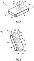
Figure 1 is a top perspective view of the packaging according to aspects of the disclosure; -
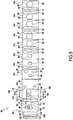
Figure 2 is a bottom perspective view of the packaging ofFigure 1 ; -
Figure 3 is a bottom perspective view of the packaging ofFigure 1 , illustrating the packaging being opened by a user; -
Figure 4 is a top perspective view of the packaging ofFigure 1 , illustrating a container of the packaging in a first position; -
Figure 5 is a top perspective view of the packaging ofFigure 1 , illustrating the container of the packaging in a second position; -
Figure 6 is a top perspective view of an alternative embodiment of the packaging ofFigure 1 , illustrating the container of the packaging between the first position and the second position; -
Figure 7 is a top perspective view of the packaging ofFigure 1 , illustrating the container of the packaging transitioning between the first position and the second position; -
Figure 8 is a top view of the packaging ofFigure 1 , illustrating the container of the packaging in the second position; -
Figure 9 is a side cross-sectional view of the packaging ofFigure 1 , taken along the line IX shown inFigure 4 ; -
Figure 10 is a front perspective view of the packaging according to aspects of the disclosure, illustrating a cover of the packaging in a converted state; -
Figure 11 is a rear perspective view of the packaging ofFigure 10 , illustrating the cover of the packaging in the converted state; and -
Figure 12 is a top perspective view of the packaging ofFigure 1 , illustrating the container of the packaging in the first position and a product positioned therein. - An embodiment of the packaging according to aspects of the disclosure will now be described with reference to
Figures 1-12 , wherein like numerals represent like parts, and will generally be referred to by thereference numeral 10. Although thepackaging 10 is described with reference to specific examples, it should be understood that modifications and changes may be made to these examples without going beyond the general scope as defined by the claims. In particular, individual characteristics of the various embodiments shown and/or mentioned herein may be combined in additional embodiments. Consequently, the description and the drawings should be considered in a sense that is illustrative rather than restrictive. The Figures, which are not necessarily to scale, depict illustrative aspects and are not intended to limit the scope of the disclosure. The illustrative aspects depicted are intended only as exemplary. - The term "exemplary" is used in the sense of "example," rather than "ideal." While aspects of the disclosure are amenable to various modifications and alternative forms, specifics thereof have been shown by way of example in the drawings and will be described in detail. It should be understood, however, that the intention is not to limit aspects of the disclosure to the particular embodiment(s) described. On the contrary, the intention of this disclosure is to cover all modifications, equivalents, and alternatives falling within the scope of the disclosure.
- Various materials, methods of construction and methods of fastening will be discussed in the context of the disclosed embodiment(s). Those skilled in the art will recognize known substitutes for the materials, construction methods, and fastening methods, all of which are contemplated as compatible with the disclosed embodiment(s) and are intended to be encompassed by the appended claims.
- As used in this disclosure and the appended claims, the singular forms "a," "an," and "the" include plural referents unless the content clearly dictates otherwise. As used in this disclosure and the appended claims, the term "or" is generally employed in its sense including "and/or" unless the content clearly dictates otherwise.
- Throughout the description, including the claims, the terms "comprising a," "including a," and "having a" should be understood as being synonymous with "comprising one or more," "including one or more," and "having one or more" unless otherwise stated. In addition, any range set forth in the description, including the claims should be understood as including its end value(s) unless otherwise stated. Specific values for described elements should be understood to be within accepted manufacturing or industry tolerances known to one of skill in the art, and any use of the terms "substantially," "approximately," and "generally" should be understood to mean falling within such accepted tolerances.
- When an element or feature is referred to herein as being "on," "engaged to," "connected to," or "coupled to" another element or feature, it may be directly on, engaged, connected, or coupled to the other element or feature, or intervening elements or features may be present. In contrast, when an element or feature is referred to as being "directly on," "directly engaged to," "directly connected to," or "directly coupled to" another element or feature, there may be no intervening elements or features present. Other words used to describe the relationship between elements or features should be interpreted in a like fashion (e.g., "between" versus "directly between," "adjacent" versus "directly adjacent," etc.).
- Spatially relative terms, such as "top," "bottom," "middle," "inner," "outer," "beneath," "below," "lower," "above," "upper," and the like, may be used herein for ease of description to describe one element or feature's relationship to another element(s) or feature(s) as illustrated in the drawings. Spatially relative terms may be intended to encompass different orientations of a device in use or operation in addition to the orientation depicted in the drawings. For example, if the device in the drawings is turned over, elements described as "below" or "beneath" other elements or features would then be oriented "above" the other elements or features. Thus, the example term "below" can encompass both an orientation of above and below. The device may be otherwise oriented (rotated 90 degrees or at other orientations) and the spatially relative descriptors used herein interpreted accordingly.
- Although the terms "first," "second," etc. may be used herein to describe various elements, components, regions, layers, sections, and/or parameters, these elements, components, regions, layers, sections, and/or parameters should not be limited by these terms. These terms are only used to distinguish one element, component, region, layer, or section from another region, layer, or section. Thus, a first element, component, region, layer, or section discussed herein could be termed a second element, component, region, layer, or section without departing from the teachings of the present inventive subject matter.
- As shown in
Figures 1-5 , thepackaging 10 may be contemplated for use with aproduct 200, such as a handheld shaving device and additional shaving device heads. The packaging may comprise acontainer 20, acover 60, a securingextension 100, and apackage opening mechanism 120. Thecontainer 20,cover 60, securingextension 100, andpackage opening mechanism 120 may all be constructed from and/or as one sheet of die-cut material and connected by folds 12 (seeFigure 8 ) to reduce the usage of environmentally harmful materials and/or excess materials. In the disclosed embodiment, the material may be corrugated cardboard, however, a person having ordinary skill in the art would understand that other materials, such as fiber, foil, cloth, paper, corrugated fiberboard, chipboard, paperboard, plastic, rubber, foam, and metal may be compatible with thepackaging 10. To allow for ease of folding, the material at eachfold 12 of thepackaging 10 may be creased, perforated or pre-cut, thinner, and/or less robust than the material used for the remaining elements of thepackaging 10. - Referring to
Figures 5-8 , thecontainer 20 may include a plurality ofbody layers fold 12 in a pleated relationship. It is also contemplated that thecontainer 20 may include afirst body layer 24a connected to thecover 60 at afold 12 and asecond body layer 24b connected to thefirst body layer 24a at afold 12. Referring to the embodiment shown inFigure 5 , the body layers 24a, 24b, 24c may include a bottom outer body layer (first body layer) 24a, a top outer body layer (second body layer) 24b, and one or more inner body layers (third body layers) 24c. In the disclosed embodiment, there may be a series of 1-20 inner body layers 24c, however the embodiment depicted inFigure 5 includes a series of 7 inner body layers 24c. The bottomouter body layer 24a may connect to oneinner body layer 24c and thecover 60 at opposing folds 12. The topouter body layer 24b may connect to the oneinner body layer 24c at afold 12. Depending on the position of theinner body layer 24c and/or the amount of inner body layers 24c, eachinner body layer 24c may connect to two other inner body layers 24c at opposingfolds 12, to one otherinner body layer 24c and the bottom or topouter body layers folds 12, or to the bottom and topouter body layers Figure 4 ) wherein the body layers 24a, 24b, 24c are folded at eachfold 12 and stacked in an aligned surface-to-surface arrangement. The body layers 24a, 24b, 24c may expand to a second position (seeFigures 5-8 ) wherein the body layers 24a, 24b, 24c are extended outwardly from thecover 60 and/or are no longer folded and stacked in an aligned surface-to-surface arrangement. Each of the body layers 24a, 24b, 24c may include one or more voids 26. Together, in the first position, thevoids 26 may define acavity 27 for receiving theproduct 200. Each of thevoids 26 may have a contour which corresponds to a specific cross-section of theproduct 200 to improve the positioning and integrity of theproduct 200 in the container 20 (seeFigure 12 ). The contour of each void 26 may have varying dimensions from onebody layer body layer product 200 at a specific height of the product 200 (seeFigures 4 and7-9 ). A varying of the "dimensions" as referred to herein should be understood to encompass a differing or changing of the size, shape, geometry, and/or relative position of the contour of each void 26. Each contour of each void 26 may include aportion 28 that flares outwardly from the contour of theproduct 200 for accommodating a finger of a user to facilitate removal of theproduct 200 from thecontainer 20. Each of the body layers 24a, 24b, 24c may define arecess 30 at opposing ends. Together, therecesses 30 form a securing port 32 (seeFigure 4 ) for mating with the securingextension 100 and thereby aligning the body layers 24a, 24b, 24c and thevoids 26 as well as improving durability of thepackaging 10. The securingport 32 may include a hanging element 33 (seeFigure 2 ). The hangingelement 33 may be a pre-cut formation which includes anextension 34 having anopening 35 for hanging thepackaging 10 on an organizational structure (not shown). Theopening 35 may have any suitable shape, such as a circle or a butterfly-shape, for hanging on the organizational structure. - As shown in
Figures 2-5 , thecover 60 may include a top (first)side 62, a bottom (second)side 64, afirst sidewall 66 linking the top andbottom sides second sidewall 68 linking thetop side 62 to thepackage opening mechanism 120. It is also contemplated that thepackage opening mechanism 120 may be positioned on the top orbottom sides cover 60. Thetop side 62 of thecover 60 may connect to the first andsecond sidewalls folds 12 and thebottom side 64 of thecover 60 may connect to thefirst sidewall 66 and the bottomouter body layer 24a at opposing folds 12. In the disclosed embodiment, there may be a pair of securingextensions 100. At opposing ends of thecover 60, each securingextension 100 may include a lower (first)section 102 connecting to thebottom side 64 of thecover 60 at afold 12 and an upper (second)section 104 connecting to thelower section 102 at afold 12. Thelower section 102 may be configured to be received by therecesses 30 defined by the body layers 24a, 24b, 24c in a press-fit arrangement, however, a person having ordinary skill in the art would understand that other mating arrangements may be compatible with the packaging. - As illustrated by
Figures 4-5 and7 , when collapsing thecontainer 20 to the first position, the bottomouter body layer 24a may fold inwardly and collapse toward thebottom side 64 of thecover 60 at thefold 12 connecting the bottomouter body layer 24a to thebottom side 64 of thecover 60 and lay against thebottom side 64 of thecover 60 in a surface-to-surface relationship. A succeedinginner body layer 24c connected at theopposite fold 12 of the bottomouter body layer 24a may fold inwardly and collapse toward thebottom side 64 of thecover 60 at thefold 12 connecting the succeedinginner body layer 24c to the bottomouter body layer 24a and lay against the bottomouter body layer 24a in a surface-to-surface relationship (seeFigure 7 ). In this manner, each successiveinner body layer 24c may fold inwardly and collapse toward thebottom side 64 of thecover 60 at thefold 12 connecting the successive inner body layers 24c with the preceding inner body layers 24c and lay against the preceding inner body layers 24c in a surface-to-surface relationship. Finally, the topouter body layer 24b may fold inwardly and collapse toward thebottom side 64 of thecover 60 at thefold 12 connecting the topouter body layer 24b to the precedinginner body layer 24c and lay against the precedinginner body layer 24c in a surface-to-surface relationship. In this arrangement, the body layers 24a, 24b, 24c may all fold and collapse into a stack ofbody layers Figure 4 ) to reduce damage to thepackaging 10 caused by impact and pressure exerted on thepackaging 10, increase durability of thepackaging 10, and improve and maintain positioning of theproduct 200 to ensure that after transportation, shipment, Point of Sale, and un-packaging the consumer will receive theproduct 200 in a manner intended by a seller. - Referring to
Figures 1 and4 , once the body layers 24a, 24b, 24c are folded and stacked on the bottom side of thecover 64, thelower section 102 of each securingextension 100 may fold inwardly toward the body layers 24a, 24b, 24c at thefold 12 connecting thelower section 102 of each securingextension 100 to thebottom side 64 of thecover 60. Thelower section 102 of each securingextension 100 may fold into and mate with each recess 30 (the securing port 32) defined at the corresponding end of eachbody layer upper section 104 of each securingextension 100 may fold at thefold 12 connecting theupper section 104 of each securingextension 100 to thelower section 102 of each securingextension 100. Theupper section 104 may fold over the topouter body layer 24b and lay against the topouter body layer 24b in a surface-to-surface relationship. Thetop side 62 of thecover 60 may fold towards the body layers 24a, 24b, 24c at thefold 12 connecting thetop side 62 of thecover 60 to thefirst sidewall 66. Thefirst sidewall 66 may lay against edges of the body layers 24a, 24b, 24c and thetop side 62 of thecover 60 may lay against theupper section 104 of the securingextensions 100 and/or the topouter body layer 24b in a surface-to-surface relationship. Thesecond sidewall 68 may then fold over the topouter body layer 24b at thefold 12 connecting thesecond sidewall 68 to thetop side 62 of thecover 60 and lay against edges of the body layers 24a, 24b, 24c. - As shown in
Figures 2 and3 , thepackage opening mechanism 120 may comprise anextension 122 which folds over thebottom side 64 of thecover 60 at thefold 12 connecting thepackage opening mechanism 120 to thesecond sidewall 68 and lay against an exterior surface of thebottom side 64 of thecover 60 in a surface-to-surface relationship. Thepackage opening mechanism 120 may include afastening portion 124 that affixes to thebottom side 64 of thecover 60. In the disclosed embodiment, thepackage opening mechanism 120 may be glued to the bottom 64 side of thecover 60, but a person having ordinary skill in the art would appreciate that other methods and materials for affixing thepackage opening mechanism 120 to thebottom side 64 of thecover 60 may be compatible with thepackaging 10. Thepackage opening mechanism 120 may include atear strip 126 which is perforated, pre-cut, and/or less robust than the material of thecover 60 to allow a user to remove thetear strip 126. Removal of thetear strip 126 may separate theextension 122, thefirst side 62, thefirst sidewall 66, and thesecond sidewall 68 of thecover 60 from thefastening portion 124 of thepackage opening mechanism 120 which is affixed to thebottom side 64 of thecover 60. Removal of thetear strip 126 may allow a user to access thecontainer 20 and/or for the body layers 24a, 24b, 24c of thecontainer 20 to expand to the second position. - As illustrated by
Figures 5-8 , expanding the body layers 24a, 24b, 24c of thecontainer 20 to the second position may allow thepackaging 10 to be disassembled. Pulling any one of the body layers 24a, 24b, 24c away from thecover 60 may expand the body layers 24a, 24b, 24c from the first position to the second position. Thecontainer 20 may separate from thecover 60 by cutting and/or tearing along thefold 12 connecting the bottomouter body layer 24a to thebottom side 64 of thecover 60. - As shown in
Figure 1 ,5-6 ,8 , and10-11 thecover 60 may include apre-cut section 70 which may be configured to be partially or wholly removed from thecover 60. The term "pre-cut section 70" as referred to herein should be understood to be asection 70 of thecover 60 having a peripheral boundary between thesection 70 and thecover 60 which may be pre-cut, perforated, and/or thinner and less robust so that thesection 70 may be readily separable from thecover 60. Further, thepre-cut section 70 of thecover 60 may be separated from the remainder of thecover 60, which is not included within the peripheral boundary, by tearing along the pre-cut boundary between thesection 70 and thecover 60. After being partially or wholly removed from thecover 60, thepre-cut section 70 may be reinserted into a channel (space) 82 defined by thecover 60 due to removal of thepre-cut section 70. Partially removing thepre-cut section 70 means that a portion of thepre-cut section 70 may comprise e.g. a fold line so that instead of being removed, thepre-cut section 70 remains connected to the top orbottom sides cover 60. In this manner, the removed portion of thepre-cut section 70 can be folded about the fold line and reinserted into thechannel 82 as described. Reinsertion of thepre-cut section 70 into thechannel 82 defined by thecover 60 may support thecover 60 in an upright position to convert thecover 60 into a stand and/or holder for theproduct 200. Thepre-cut section 70 may extend from thetop side 62 of thecover 60, through thefirst sidewall 66, to thebottom side 64 of thecover 60. A person having ordinary skill in the art would understand that conversion of thecover 60 into a stand and/or holder for theproduct 200 may be a functionality that may exist independent of thecontainer 20. As such, to convert thecover 60 into a holder for theproduct 200, a user may remove the body layers 24a, 24b, 24c, the lower andupper sections extension 100, and theextension 122. Thepre-cut section 70 of the top orbottom sides cover 60 may take the form of a hook (first segment) 72. In the disclosed embodiment, thehook 72 is in the shape of a double-ended "T" having a pair ofarms 74 at each end. There may be further pre-cuts along aninner center portion 80 at an end of thehook 72. Thepre-cut section 70 of the bottom ortop side cover 60 and thefirst sidewall 66 may take the form of a support (second segment) 76. In the disclosed embodiment, thesupport 76 is in the shape of an elongated rectangle. There may be further pre-cuts along an ovular or annularinner portion 78 of thesupport 76. Referring toFigures 10-11 , removal of thepre-cut section 70 from thecover 60 may define thechannel 82 throughout thetop side 62,bottom side 64, andfirst sidewall 66 of thecover 60 in the area previously occupied by the removedpre-cut section 70. The term "removed" as used herein should be understood to mean that an element is detached and/or delimited, wholly or partially, from an element in which it was previously a part of. The top andbottom sides cover 60 may be folded toward each other such that each of the top andbottom sides hook 72 may then be positioned to extend through thechannel 82 so that each pair ofarms 74 anchor against exterior surfaces of the first andsecond sides cover 60 to function as a brace for thecover 60. Thesupport 76 may extend from an end of thehook 72 to a surface below to support thehook 72 within thechannel 82. Thepre-cut center portion 80 at the end of thehook 72 and the pre-cut ovularinner portion 78 may be removed to define aslot 84 and anopening 86, respectively, for holding theproduct 200 in an upright position. Thesecond sidewall 68 may be folded inwardly from thetop side 62 of thecover 60 to lie against a surface, such as a table, to support thecover 60 in an upright position. - The
packaging 10 may include a near-field communication (NFC) chip (not shown) embedded in or attached to thecover 60,container 20, securingextensions 100, orpackage opening mechanism 120 to enable communication with an electronic device exterior to thepackaging 10. - Although the present disclosure herein has been described with reference to particular embodiments, it is to be understood that these embodiments are merely illustrative of the principles and applications of the present disclosure.
- It is intended that the specification and examples be considered as exemplary only, with a true scope of the disclosure being indicated by the following claims.
- Additionally, all of the disclosed features of an apparatus may be transposed, alone or in combination, to a method and vice versa.
Claims (15)
- A packaging (10) for a product (200) comprising:a container (20) including a first body layer (24a) and a second body layer (24b) connected at a fold (12), said first and second body layers (24a, 24b) capable of collapsing to a first position and expanding to a second position, and one or more of said first and second body layers (24a, 24b) defining a void (26); anda cover (60) including a first side (62) and a second side (64), said first and second body layers (24a, 24b) being configured to collapse to the first position between the first and second sides (62, 64) of the cover (60).
- The packaging (10) of claim 1, wherein the cover (60) includes a sidewall (66) and the first and second sides (62, 64) are connected to the sidewall (66) at respective folds (12).
- The packaging (10) of any of claims 1-2, wherein the cover (60) includes a package opening mechanism (120).
- The packaging (10) of any of claims 1-3, wherein said container (20) includes one or more inner body layers (24c) between the first and second body layers (24a, 24b), said first body layer (24a), second body layer (24b), and one or more inner body layers (24c) are connected at respective folds (12).
- The packaging (10) of any of claims 1-4, wherein each of said body layers (24a, 24b, 24c) comprise a void (26) having a contour and together the voids (26) form a cavity (27) in the first position.
- The packaging (10) of claim 5, wherein one or more of the contours has different dimensions.
- The packaging (10) of any of claims 1-6, wherein the second side of the cover (64) is connected to a body layer (24a, 24b, 24c) at a fold (12).
- The packaging (10) of any of claims 1-7, wherein the cover (60) includes one or more extensions (100) capable of mating with one or more body layers (24a, 24b, 24c).
- The packaging (10) of any of claims 1-8, wherein the cover (60) faces the body layers (24a, 24b, 24c) when the body layers (24a, 24b, 24c) are in the first position.
- The packaging (10) of any of claims 1-9, wherein the body layers (24a, 24b, 24c) are configured in a stacked arrangement in the first position.
- The packaging (10) of any of claims 1-10, wherein the container (20) and the cover (60) are constructed as one sheet.
- The packaging (10) of any of claims 1-11, wherein the cover (60) includes a pre-cut section (70) configured to be removed, removal of the pre-cut section (70) defines a channel (82) in the cover (60), and reinsertion of the pre-cut section (70) into the channel (82) supports the cover (60) in an upright position.
- A method of making a holder for a product (100) out of a packaging (10) comprising:providing a packaging (10) having a first side (62), a second side (64), and a pre-cut section (70) extending through the first side (62) and the second sides (64);removing the pre-cut section (70) from the packaging (10) to define a channel (82);folding the first side (62) toward the second side (64); andreinserting the pre-cut section (70) into the channel (82) to support the packaging (10) in an upright position.
- The method of claim 13, wherein the step of providing a packaging (10) includes the pre-cut section (70) having a hook (72) configured to extend through the channel (82) and anchor against exterior surfaces of the first and second sides (62, 64) and a support (76) extending from the hook (72) configured to support the hook (72) within the channel (82).
- The method of any of claims 13-14, wherein the step of providing a packaging (10) includes the pre-cut section (70) having further pre-cuts along one or more inner portions (78, 80) configured to be removed to receive the product (100).
Priority Applications (2)
| Application Number | Priority Date | Filing Date | Title |
|---|---|---|---|
| EP19212509.4A EP3828092B1 (en) | 2019-11-29 | 2019-11-29 | Packaging device |
| US17/083,614 US11479395B2 (en) | 2019-11-29 | 2020-10-29 | Packaging device and method |
Applications Claiming Priority (1)
| Application Number | Priority Date | Filing Date | Title |
|---|---|---|---|
| EP19212509.4A EP3828092B1 (en) | 2019-11-29 | 2019-11-29 | Packaging device |
Publications (2)
| Publication Number | Publication Date |
|---|---|
| EP3828092A1 true EP3828092A1 (en) | 2021-06-02 |
| EP3828092B1 EP3828092B1 (en) | 2024-02-14 |
Family
ID=68806550
Family Applications (1)
| Application Number | Title | Priority Date | Filing Date |
|---|---|---|---|
| EP19212509.4A Active EP3828092B1 (en) | 2019-11-29 | 2019-11-29 | Packaging device |
Country Status (2)
| Country | Link |
|---|---|
| US (1) | US11479395B2 (en) |
| EP (1) | EP3828092B1 (en) |
Families Citing this family (4)
| Publication number | Priority date | Publication date | Assignee | Title |
|---|---|---|---|---|
| US20220332000A1 (en) * | 2021-04-20 | 2022-10-20 | The Gillette Company Llc | Consumer product package |
| USD1003705S1 (en) * | 2021-04-20 | 2023-11-07 | The Gillette Company Llc | Consumer product package |
| US20240023692A1 (en) * | 2022-07-21 | 2024-01-25 | Benjamin Avery | Razor Cartridge Packaging |
| EP4491148A1 (en) * | 2023-07-10 | 2025-01-15 | Ivoclar Vivadent AG | Receptacle for a dental blank |
Citations (5)
| Publication number | Priority date | Publication date | Assignee | Title |
|---|---|---|---|---|
| US3567103A (en) * | 1969-04-23 | 1971-03-02 | Robert F Seifert | Composite spacer and liner member for shipping containers |
| US3927767A (en) * | 1972-06-01 | 1975-12-23 | Tokyo Shibaura Electric Co | Packaging unit |
| EP1174350A1 (en) * | 2000-07-19 | 2002-01-23 | Kappa Wellpappe Wiesloch, Zweigniederlassung der Kappa Holfelder Werke GmbH & Co. KG | Shipping container for medical diagnostic specimens |
| WO2010007410A1 (en) * | 2008-07-14 | 2010-01-21 | Parasol I.P.S. Limited | Collapsible pack with inner flap |
| US20160325875A1 (en) * | 2015-05-08 | 2016-11-10 | Shinwa Technology Limited | Packing box of portable device |
Family Cites Families (21)
| Publication number | Priority date | Publication date | Assignee | Title |
|---|---|---|---|---|
| US2959340A (en) * | 1956-10-15 | 1960-11-08 | Waldorf Paper Prod Co | Pad for packing articles |
| US3239177A (en) | 1964-02-07 | 1966-03-08 | Gillette Co | Display stand for shaving and toilet articles |
| US3332542A (en) | 1964-09-24 | 1967-07-25 | Gillette Co | Convertible container and display stand |
| US3410476A (en) * | 1966-05-11 | 1968-11-12 | Brown Co | Recloseable carton having improved tear strip |
| US3981434A (en) * | 1975-04-10 | 1976-09-21 | American Can Company | Easy opening carton for frozen comestible |
| US4239115A (en) * | 1977-10-17 | 1980-12-16 | Rendoll Paper Corporation | Folding ice-cream carton and carton blank therefor |
| US4838432A (en) * | 1987-10-13 | 1989-06-13 | Somerville Packaging Corporation | Carton and blank for packaging ice cream and the like |
| US4919271A (en) * | 1988-11-14 | 1990-04-24 | James River Corporation | Carton with tear strip |
| US5121838A (en) * | 1991-10-23 | 1992-06-16 | Intepac Technologies Inc. | Package having product clamping for card-like products |
| NL9201375A (en) | 1992-07-30 | 1994-02-16 | Philips Electronics Nv | Storage and display box (case) |
| US5295580A (en) * | 1992-10-19 | 1994-03-22 | Hicks Stewart W | Container with overlapping flap closure and nesting spacer |
| US5454180A (en) | 1993-02-26 | 1995-10-03 | Volpe; James R. | Pre-assembled self erecting display |
| US5862816A (en) | 1997-08-19 | 1999-01-26 | Lowe Technology Products | Mirror-razor combination and method |
| US6415517B1 (en) | 1999-07-29 | 2002-07-09 | The Gillette Company | Storage device for shaving razor, cartridges, or other stored items |
| US6227444B1 (en) * | 2000-02-17 | 2001-05-08 | Pama Enterprises, Inc. | Expandable envelope construction |
| US6520328B2 (en) | 2001-02-28 | 2003-02-18 | Warner-Lambert Company | Retail razor display package with razor stand |
| US20050218033A1 (en) | 2001-09-28 | 2005-10-06 | Curtis Stephen L | Portable shaving kit |
| US7070048B2 (en) * | 2001-12-11 | 2006-07-04 | Meadwestvaco Corporation | Packaging for multiple media discs and methods for making same |
| GB2434982A (en) | 2006-02-09 | 2007-08-15 | Raymond Richmond | Grooming item storage pack operable between a compacted condition and an expanded condition wherein it may be stood upon a flat surface. |
| US8292095B2 (en) | 2009-04-29 | 2012-10-23 | Rock-Tenn Shared Services, Llc | Expandable display system |
| US20150344216A1 (en) * | 2014-05-30 | 2015-12-03 | Indiana Carton Company, Inc. | Folding cupcake box |
-
2019
- 2019-11-29 EP EP19212509.4A patent/EP3828092B1/en active Active
-
2020
- 2020-10-29 US US17/083,614 patent/US11479395B2/en active Active
Patent Citations (5)
| Publication number | Priority date | Publication date | Assignee | Title |
|---|---|---|---|---|
| US3567103A (en) * | 1969-04-23 | 1971-03-02 | Robert F Seifert | Composite spacer and liner member for shipping containers |
| US3927767A (en) * | 1972-06-01 | 1975-12-23 | Tokyo Shibaura Electric Co | Packaging unit |
| EP1174350A1 (en) * | 2000-07-19 | 2002-01-23 | Kappa Wellpappe Wiesloch, Zweigniederlassung der Kappa Holfelder Werke GmbH & Co. KG | Shipping container for medical diagnostic specimens |
| WO2010007410A1 (en) * | 2008-07-14 | 2010-01-21 | Parasol I.P.S. Limited | Collapsible pack with inner flap |
| US20160325875A1 (en) * | 2015-05-08 | 2016-11-10 | Shinwa Technology Limited | Packing box of portable device |
Also Published As
| Publication number | Publication date |
|---|---|
| US11479395B2 (en) | 2022-10-25 |
| US20210163200A1 (en) | 2021-06-03 |
| EP3828092B1 (en) | 2024-02-14 |
Similar Documents
| Publication | Publication Date | Title |
|---|---|---|
| US11479395B2 (en) | Packaging device and method | |
| US20190315564A1 (en) | Apparatus and methods for packaging and shipping wine bottles | |
| CA2834089C (en) | Shipping and display container | |
| CN106255646A (en) | There is the shelf package of structural intergrity and for the method preparing them | |
| JP2019182438A (en) | Packing box and method for improving taking-out easiness of content | |
| WO2012119198A1 (en) | Shelf-ready packaging | |
| JP2009035260A (en) | Package | |
| KR102049057B1 (en) | Packing Box with Handle | |
| CN107140277A (en) | Paper card packaging structure and product packaging method | |
| JP4641769B2 (en) | Tray with divider | |
| CN215664468U (en) | Packing box | |
| CN206766546U (en) | Paper card packaging structure | |
| CN206511267U (en) | Packing box | |
| CN221368053U (en) | Fixed shock-absorbing selling integrated vase packaging carton | |
| CN216612371U (en) | Packaging box for book end | |
| CN221317128U (en) | Portable paper packing box | |
| CN215044516U (en) | Folding cutter packing box | |
| JP3174612U (en) | box | |
| CN205186951U (en) | Kettle packing is held in hand to spherical two -piece -dress of slightly making pottery | |
| WO2000076877A1 (en) | Stackable packaging system | |
| CN213229362U (en) | Conjoined inner card packing box | |
| JP4311229B2 (en) | Foldable container paper cover with lid | |
| AU2012225203B2 (en) | Shelf-ready packaging | |
| KR20060038084A (en) | Folding box with folding structure | |
| JP2009096513A (en) | Carry carton |
Legal Events
| Date | Code | Title | Description |
|---|---|---|---|
| PUAI | Public reference made under article 153(3) epc to a published international application that has entered the european phase |
Free format text: ORIGINAL CODE: 0009012 |
|
| STAA | Information on the status of an ep patent application or granted ep patent |
Free format text: STATUS: THE APPLICATION HAS BEEN PUBLISHED |
|
| AK | Designated contracting states |
Kind code of ref document: A1 Designated state(s): AL AT BE BG CH CY CZ DE DK EE ES FI FR GB GR HR HU IE IS IT LI LT LU LV MC MK MT NL NO PL PT RO RS SE SI SK SM TR |
|
| STAA | Information on the status of an ep patent application or granted ep patent |
Free format text: STATUS: REQUEST FOR EXAMINATION WAS MADE |
|
| 17P | Request for examination filed |
Effective date: 20211202 |
|
| RBV | Designated contracting states (corrected) |
Designated state(s): AL AT BE BG CH CY CZ DE DK EE ES FI FR GB GR HR HU IE IS IT LI LT LU LV MC MK MT NL NO PL PT RO RS SE SI SK SM TR |
|
| RAP3 | Party data changed (applicant data changed or rights of an application transferred) |
Owner name: BIC VIOLEX SINGLE MEMBER S.A. |
|
| STAA | Information on the status of an ep patent application or granted ep patent |
Free format text: STATUS: EXAMINATION IS IN PROGRESS |
|
| 17Q | First examination report despatched |
Effective date: 20230207 |
|
| GRAP | Despatch of communication of intention to grant a patent |
Free format text: ORIGINAL CODE: EPIDOSNIGR1 |
|
| STAA | Information on the status of an ep patent application or granted ep patent |
Free format text: STATUS: GRANT OF PATENT IS INTENDED |
|
| INTG | Intention to grant announced |
Effective date: 20230907 |
|
| GRAS | Grant fee paid |
Free format text: ORIGINAL CODE: EPIDOSNIGR3 |
|
| GRAA | (expected) grant |
Free format text: ORIGINAL CODE: 0009210 |
|
| STAA | Information on the status of an ep patent application or granted ep patent |
Free format text: STATUS: THE PATENT HAS BEEN GRANTED |
|
| AK | Designated contracting states |
Kind code of ref document: B1 Designated state(s): AL AT BE BG CH CY CZ DE DK EE ES FI FR GB GR HR HU IE IS IT LI LT LU LV MC MK MT NL NO PL PT RO RS SE SI SK SM TR |
|
| REG | Reference to a national code |
Ref country code: GB Ref legal event code: FG4D |
|
| REG | Reference to a national code |
Ref country code: CH Ref legal event code: EP |
|
| REG | Reference to a national code |
Ref country code: DE Ref legal event code: R096 Ref document number: 602019046432 Country of ref document: DE |
|
| REG | Reference to a national code |
Ref country code: IE Ref legal event code: FG4D |
|
| REG | Reference to a national code |
Ref country code: LT Ref legal event code: MG9D |
|
| REG | Reference to a national code |
Ref country code: NL Ref legal event code: MP Effective date: 20240214 |
|
| PG25 | Lapsed in a contracting state [announced via postgrant information from national office to epo] |
Ref country code: IS Free format text: LAPSE BECAUSE OF FAILURE TO SUBMIT A TRANSLATION OF THE DESCRIPTION OR TO PAY THE FEE WITHIN THE PRESCRIBED TIME-LIMIT Effective date: 20240614 |
|
| PG25 | Lapsed in a contracting state [announced via postgrant information from national office to epo] |
Ref country code: LT Free format text: LAPSE BECAUSE OF FAILURE TO SUBMIT A TRANSLATION OF THE DESCRIPTION OR TO PAY THE FEE WITHIN THE PRESCRIBED TIME-LIMIT Effective date: 20240214 |
|
| PG25 | Lapsed in a contracting state [announced via postgrant information from national office to epo] |
Ref country code: GR Free format text: LAPSE BECAUSE OF FAILURE TO SUBMIT A TRANSLATION OF THE DESCRIPTION OR TO PAY THE FEE WITHIN THE PRESCRIBED TIME-LIMIT Effective date: 20240515 |
|
| REG | Reference to a national code |
Ref country code: AT Ref legal event code: MK05 Ref document number: 1656879 Country of ref document: AT Kind code of ref document: T Effective date: 20240214 |
|
| PG25 | Lapsed in a contracting state [announced via postgrant information from national office to epo] |
Ref country code: NL Free format text: LAPSE BECAUSE OF FAILURE TO SUBMIT A TRANSLATION OF THE DESCRIPTION OR TO PAY THE FEE WITHIN THE PRESCRIBED TIME-LIMIT Effective date: 20240214 Ref country code: RS Free format text: LAPSE BECAUSE OF FAILURE TO SUBMIT A TRANSLATION OF THE DESCRIPTION OR TO PAY THE FEE WITHIN THE PRESCRIBED TIME-LIMIT Effective date: 20240514 Ref country code: HR Free format text: LAPSE BECAUSE OF FAILURE TO SUBMIT A TRANSLATION OF THE DESCRIPTION OR TO PAY THE FEE WITHIN THE PRESCRIBED TIME-LIMIT Effective date: 20240214 |
|
| PG25 | Lapsed in a contracting state [announced via postgrant information from national office to epo] |
Ref country code: ES Free format text: LAPSE BECAUSE OF FAILURE TO SUBMIT A TRANSLATION OF THE DESCRIPTION OR TO PAY THE FEE WITHIN THE PRESCRIBED TIME-LIMIT Effective date: 20240214 |
|
| PG25 | Lapsed in a contracting state [announced via postgrant information from national office to epo] |
Ref country code: AT Free format text: LAPSE BECAUSE OF FAILURE TO SUBMIT A TRANSLATION OF THE DESCRIPTION OR TO PAY THE FEE WITHIN THE PRESCRIBED TIME-LIMIT Effective date: 20240214 |
|
| PG25 | Lapsed in a contracting state [announced via postgrant information from national office to epo] |
Ref country code: RS Free format text: LAPSE BECAUSE OF FAILURE TO SUBMIT A TRANSLATION OF THE DESCRIPTION OR TO PAY THE FEE WITHIN THE PRESCRIBED TIME-LIMIT Effective date: 20240514 Ref country code: NO Free format text: LAPSE BECAUSE OF FAILURE TO SUBMIT A TRANSLATION OF THE DESCRIPTION OR TO PAY THE FEE WITHIN THE PRESCRIBED TIME-LIMIT Effective date: 20240514 Ref country code: NL Free format text: LAPSE BECAUSE OF FAILURE TO SUBMIT A TRANSLATION OF THE DESCRIPTION OR TO PAY THE FEE WITHIN THE PRESCRIBED TIME-LIMIT Effective date: 20240214 Ref country code: LT Free format text: LAPSE BECAUSE OF FAILURE TO SUBMIT A TRANSLATION OF THE DESCRIPTION OR TO PAY THE FEE WITHIN THE PRESCRIBED TIME-LIMIT Effective date: 20240214 Ref country code: IS Free format text: LAPSE BECAUSE OF FAILURE TO SUBMIT A TRANSLATION OF THE DESCRIPTION OR TO PAY THE FEE WITHIN THE PRESCRIBED TIME-LIMIT Effective date: 20240614 Ref country code: HR Free format text: LAPSE BECAUSE OF FAILURE TO SUBMIT A TRANSLATION OF THE DESCRIPTION OR TO PAY THE FEE WITHIN THE PRESCRIBED TIME-LIMIT Effective date: 20240214 Ref country code: GR Free format text: LAPSE BECAUSE OF FAILURE TO SUBMIT A TRANSLATION OF THE DESCRIPTION OR TO PAY THE FEE WITHIN THE PRESCRIBED TIME-LIMIT Effective date: 20240515 Ref country code: FI Free format text: LAPSE BECAUSE OF FAILURE TO SUBMIT A TRANSLATION OF THE DESCRIPTION OR TO PAY THE FEE WITHIN THE PRESCRIBED TIME-LIMIT Effective date: 20240214 Ref country code: ES Free format text: LAPSE BECAUSE OF FAILURE TO SUBMIT A TRANSLATION OF THE DESCRIPTION OR TO PAY THE FEE WITHIN THE PRESCRIBED TIME-LIMIT Effective date: 20240214 Ref country code: BG Free format text: LAPSE BECAUSE OF FAILURE TO SUBMIT A TRANSLATION OF THE DESCRIPTION OR TO PAY THE FEE WITHIN THE PRESCRIBED TIME-LIMIT Effective date: 20240214 Ref country code: AT Free format text: LAPSE BECAUSE OF FAILURE TO SUBMIT A TRANSLATION OF THE DESCRIPTION OR TO PAY THE FEE WITHIN THE PRESCRIBED TIME-LIMIT Effective date: 20240214 |
|
| PG25 | Lapsed in a contracting state [announced via postgrant information from national office to epo] |
Ref country code: PL Free format text: LAPSE BECAUSE OF FAILURE TO SUBMIT A TRANSLATION OF THE DESCRIPTION OR TO PAY THE FEE WITHIN THE PRESCRIBED TIME-LIMIT Effective date: 20240214 Ref country code: PT Free format text: LAPSE BECAUSE OF FAILURE TO SUBMIT A TRANSLATION OF THE DESCRIPTION OR TO PAY THE FEE WITHIN THE PRESCRIBED TIME-LIMIT Effective date: 20240614 |
|
| PG25 | Lapsed in a contracting state [announced via postgrant information from national office to epo] |
Ref country code: SE Free format text: LAPSE BECAUSE OF FAILURE TO SUBMIT A TRANSLATION OF THE DESCRIPTION OR TO PAY THE FEE WITHIN THE PRESCRIBED TIME-LIMIT Effective date: 20240214 Ref country code: PT Free format text: LAPSE BECAUSE OF FAILURE TO SUBMIT A TRANSLATION OF THE DESCRIPTION OR TO PAY THE FEE WITHIN THE PRESCRIBED TIME-LIMIT Effective date: 20240614 Ref country code: PL Free format text: LAPSE BECAUSE OF FAILURE TO SUBMIT A TRANSLATION OF THE DESCRIPTION OR TO PAY THE FEE WITHIN THE PRESCRIBED TIME-LIMIT Effective date: 20240214 Ref country code: LV Free format text: LAPSE BECAUSE OF FAILURE TO SUBMIT A TRANSLATION OF THE DESCRIPTION OR TO PAY THE FEE WITHIN THE PRESCRIBED TIME-LIMIT Effective date: 20240214 |
|
| PG25 | Lapsed in a contracting state [announced via postgrant information from national office to epo] |
Ref country code: DK Free format text: LAPSE BECAUSE OF FAILURE TO SUBMIT A TRANSLATION OF THE DESCRIPTION OR TO PAY THE FEE WITHIN THE PRESCRIBED TIME-LIMIT Effective date: 20240214 |
|
| PG25 | Lapsed in a contracting state [announced via postgrant information from national office to epo] |
Ref country code: SM Free format text: LAPSE BECAUSE OF FAILURE TO SUBMIT A TRANSLATION OF THE DESCRIPTION OR TO PAY THE FEE WITHIN THE PRESCRIBED TIME-LIMIT Effective date: 20240214 |
|
| PG25 | Lapsed in a contracting state [announced via postgrant information from national office to epo] |
Ref country code: CZ Free format text: LAPSE BECAUSE OF FAILURE TO SUBMIT A TRANSLATION OF THE DESCRIPTION OR TO PAY THE FEE WITHIN THE PRESCRIBED TIME-LIMIT Effective date: 20240214 Ref country code: EE Free format text: LAPSE BECAUSE OF FAILURE TO SUBMIT A TRANSLATION OF THE DESCRIPTION OR TO PAY THE FEE WITHIN THE PRESCRIBED TIME-LIMIT Effective date: 20240214 |
|
| PG25 | Lapsed in a contracting state [announced via postgrant information from national office to epo] |
Ref country code: SK Free format text: LAPSE BECAUSE OF FAILURE TO SUBMIT A TRANSLATION OF THE DESCRIPTION OR TO PAY THE FEE WITHIN THE PRESCRIBED TIME-LIMIT Effective date: 20240214 |
|
| PG25 | Lapsed in a contracting state [announced via postgrant information from national office to epo] |
Ref country code: SM Free format text: LAPSE BECAUSE OF FAILURE TO SUBMIT A TRANSLATION OF THE DESCRIPTION OR TO PAY THE FEE WITHIN THE PRESCRIBED TIME-LIMIT Effective date: 20240214 Ref country code: SK Free format text: LAPSE BECAUSE OF FAILURE TO SUBMIT A TRANSLATION OF THE DESCRIPTION OR TO PAY THE FEE WITHIN THE PRESCRIBED TIME-LIMIT Effective date: 20240214 Ref country code: RO Free format text: LAPSE BECAUSE OF FAILURE TO SUBMIT A TRANSLATION OF THE DESCRIPTION OR TO PAY THE FEE WITHIN THE PRESCRIBED TIME-LIMIT Effective date: 20240214 Ref country code: EE Free format text: LAPSE BECAUSE OF FAILURE TO SUBMIT A TRANSLATION OF THE DESCRIPTION OR TO PAY THE FEE WITHIN THE PRESCRIBED TIME-LIMIT Effective date: 20240214 Ref country code: DK Free format text: LAPSE BECAUSE OF FAILURE TO SUBMIT A TRANSLATION OF THE DESCRIPTION OR TO PAY THE FEE WITHIN THE PRESCRIBED TIME-LIMIT Effective date: 20240214 Ref country code: CZ Free format text: LAPSE BECAUSE OF FAILURE TO SUBMIT A TRANSLATION OF THE DESCRIPTION OR TO PAY THE FEE WITHIN THE PRESCRIBED TIME-LIMIT Effective date: 20240214 |
|
| REG | Reference to a national code |
Ref country code: DE Ref legal event code: R097 Ref document number: 602019046432 Country of ref document: DE |
|
| PG25 | Lapsed in a contracting state [announced via postgrant information from national office to epo] |
Ref country code: IT Free format text: LAPSE BECAUSE OF FAILURE TO SUBMIT A TRANSLATION OF THE DESCRIPTION OR TO PAY THE FEE WITHIN THE PRESCRIBED TIME-LIMIT Effective date: 20240214 |
|
| PLBE | No opposition filed within time limit |
Free format text: ORIGINAL CODE: 0009261 |
|
| STAA | Information on the status of an ep patent application or granted ep patent |
Free format text: STATUS: NO OPPOSITION FILED WITHIN TIME LIMIT |
|
| PG25 | Lapsed in a contracting state [announced via postgrant information from national office to epo] |
Ref country code: IT Free format text: LAPSE BECAUSE OF FAILURE TO SUBMIT A TRANSLATION OF THE DESCRIPTION OR TO PAY THE FEE WITHIN THE PRESCRIBED TIME-LIMIT Effective date: 20240214 |
|
| PGFP | Annual fee paid to national office [announced via postgrant information from national office to epo] |
Ref country code: DE Payment date: 20241022 Year of fee payment: 6 |
|
| PGFP | Annual fee paid to national office [announced via postgrant information from national office to epo] |
Ref country code: GB Payment date: 20241023 Year of fee payment: 6 |
|
| 26N | No opposition filed |
Effective date: 20241115 |
|
| PGFP | Annual fee paid to national office [announced via postgrant information from national office to epo] |
Ref country code: FR Payment date: 20241022 Year of fee payment: 6 |
|
| PG25 | Lapsed in a contracting state [announced via postgrant information from national office to epo] |
Ref country code: SI Free format text: LAPSE BECAUSE OF FAILURE TO SUBMIT A TRANSLATION OF THE DESCRIPTION OR TO PAY THE FEE WITHIN THE PRESCRIBED TIME-LIMIT Effective date: 20240214 |
|
| REG | Reference to a national code |
Ref country code: CH Ref legal event code: PL |
|
| PG25 | Lapsed in a contracting state [announced via postgrant information from national office to epo] |
Ref country code: MC Free format text: LAPSE BECAUSE OF FAILURE TO SUBMIT A TRANSLATION OF THE DESCRIPTION OR TO PAY THE FEE WITHIN THE PRESCRIBED TIME-LIMIT Effective date: 20240214 |
|
| PG25 | Lapsed in a contracting state [announced via postgrant information from national office to epo] |
Ref country code: LU Free format text: LAPSE BECAUSE OF NON-PAYMENT OF DUE FEES Effective date: 20241129 |
|
| REG | Reference to a national code |
Ref country code: CH Ref legal event code: PL |
|
| PG25 | Lapsed in a contracting state [announced via postgrant information from national office to epo] |
Ref country code: CH Free format text: LAPSE BECAUSE OF NON-PAYMENT OF DUE FEES Effective date: 20241130 |
|
| REG | Reference to a national code |
Ref country code: BE Ref legal event code: MM Effective date: 20241130 |
|
| PG25 | Lapsed in a contracting state [announced via postgrant information from national office to epo] |
Ref country code: BE Free format text: LAPSE BECAUSE OF NON-PAYMENT OF DUE FEES Effective date: 20241130 |
|
| PG25 | Lapsed in a contracting state [announced via postgrant information from national office to epo] |
Ref country code: IE Free format text: LAPSE BECAUSE OF NON-PAYMENT OF DUE FEES Effective date: 20241129 |
|
| PG25 | Lapsed in a contracting state [announced via postgrant information from national office to epo] |
Ref country code: HU Free format text: LAPSE BECAUSE OF FAILURE TO SUBMIT A TRANSLATION OF THE DESCRIPTION OR TO PAY THE FEE WITHIN THE PRESCRIBED TIME-LIMIT; INVALID AB INITIO Effective date: 20191129 |
|
| PG25 | Lapsed in a contracting state [announced via postgrant information from national office to epo] |
Ref country code: CY Free format text: LAPSE BECAUSE OF FAILURE TO SUBMIT A TRANSLATION OF THE DESCRIPTION OR TO PAY THE FEE WITHIN THE PRESCRIBED TIME-LIMIT; INVALID AB INITIO Effective date: 20191129 |
|
| PG25 | Lapsed in a contracting state [announced via postgrant information from national office to epo] |
Ref country code: TR Free format text: LAPSE BECAUSE OF FAILURE TO SUBMIT A TRANSLATION OF THE DESCRIPTION OR TO PAY THE FEE WITHIN THE PRESCRIBED TIME-LIMIT Effective date: 20240214 |
|
| REG | Reference to a national code |
Ref country code: DE Ref legal event code: R119 Ref document number: 602019046432 Country of ref document: DE |