EP3828079A1 - Aircraft landing gear assembly - Google Patents
Aircraft landing gear assembly Download PDFInfo
- Publication number
- EP3828079A1 EP3828079A1 EP20213970.5A EP20213970A EP3828079A1 EP 3828079 A1 EP3828079 A1 EP 3828079A1 EP 20213970 A EP20213970 A EP 20213970A EP 3828079 A1 EP3828079 A1 EP 3828079A1
- Authority
- EP
- European Patent Office
- Prior art keywords
- bogie
- bogie beam
- axle
- landing gear
- wheel
- Prior art date
- Legal status (The legal status is an assumption and is not a legal conclusion. Google has not performed a legal analysis and makes no representation as to the accuracy of the status listed.)
- Granted
Links
Images



Classifications
-
- B—PERFORMING OPERATIONS; TRANSPORTING
- B64—AIRCRAFT; AVIATION; COSMONAUTICS
- B64C—AEROPLANES; HELICOPTERS
- B64C25/00—Alighting gear
- B64C25/32—Alighting gear characterised by elements which contact the ground or similar surface
- B64C25/34—Alighting gear characterised by elements which contact the ground or similar surface wheeled type, e.g. multi-wheeled bogies
-
- B—PERFORMING OPERATIONS; TRANSPORTING
- B64—AIRCRAFT; AVIATION; COSMONAUTICS
- B64C—AEROPLANES; HELICOPTERS
- B64C25/00—Alighting gear
- B64C25/32—Alighting gear characterised by elements which contact the ground or similar surface
- B64C25/34—Alighting gear characterised by elements which contact the ground or similar surface wheeled type, e.g. multi-wheeled bogies
- B64C25/36—Arrangements or adaptations of wheels, tyres or axles in general
-
- B—PERFORMING OPERATIONS; TRANSPORTING
- B60—VEHICLES IN GENERAL
- B60B—VEHICLE WHEELS; CASTORS; AXLES FOR WHEELS OR CASTORS; INCREASING WHEEL ADHESION
- B60B35/00—Axle units; Parts thereof ; Arrangements for lubrication of axles
- B60B35/02—Dead axles, i.e. not transmitting torque
-
- B—PERFORMING OPERATIONS; TRANSPORTING
- B64—AIRCRAFT; AVIATION; COSMONAUTICS
- B64C—AEROPLANES; HELICOPTERS
- B64C25/00—Alighting gear
- B64C25/02—Undercarriages
-
- B—PERFORMING OPERATIONS; TRANSPORTING
- B60—VEHICLES IN GENERAL
- B60B—VEHICLE WHEELS; CASTORS; AXLES FOR WHEELS OR CASTORS; INCREASING WHEEL ADHESION
- B60B2360/00—Materials; Physical forms thereof
- B60B2360/14—Physical forms of metallic parts
- B60B2360/144—Tubes, i.e. being hollow
- B60B2360/1442—Tubes, i.e. being hollow of circular cross section
-
- B—PERFORMING OPERATIONS; TRANSPORTING
- B60—VEHICLES IN GENERAL
- B60B—VEHICLE WHEELS; CASTORS; AXLES FOR WHEELS OR CASTORS; INCREASING WHEEL ADHESION
- B60B2360/00—Materials; Physical forms thereof
- B60B2360/14—Physical forms of metallic parts
- B60B2360/145—Profiles, i.e. being solid and having irregular cross-section
- B60B2360/1454—T or H-Profiles
-
- B—PERFORMING OPERATIONS; TRANSPORTING
- B60—VEHICLES IN GENERAL
- B60B—VEHICLE WHEELS; CASTORS; AXLES FOR WHEELS OR CASTORS; INCREASING WHEEL ADHESION
- B60B2900/00—Purpose of invention
- B60B2900/10—Reduction of
- B60B2900/111—Weight
-
- B—PERFORMING OPERATIONS; TRANSPORTING
- B60—VEHICLES IN GENERAL
- B60B—VEHICLE WHEELS; CASTORS; AXLES FOR WHEELS OR CASTORS; INCREASING WHEEL ADHESION
- B60B2900/00—Purpose of invention
- B60B2900/30—Increase in
- B60B2900/331—Safety or security
- B60B2900/3312—Safety or security during regular use
-
- B—PERFORMING OPERATIONS; TRANSPORTING
- B60—VEHICLES IN GENERAL
- B60Y—INDEXING SCHEME RELATING TO ASPECTS CROSS-CUTTING VEHICLE TECHNOLOGY
- B60Y2200/00—Type of vehicle
- B60Y2200/50—Aeroplanes, Helicopters
- B60Y2200/51—Aeroplanes
Definitions
- An aircraft landing gear for medium to large aircraft typically includes a pair of wheel assemblies mounted on a common axle.
- a landing gear may include an elongate bogie beam which supports two or more axles, each of which carries a pair of wheel assemblies.
- a landing gear is designed to withstand operation loads when one of the tyres on an axle is deflated. In the case of a multi axle landing gear, the gear must be designed to withstand operation loads arising from a worst case combination of deflated tyres.
- the present inventor has identified that the weight of known landing gear can be reduced.
- the following aspects of the invention provide alternative solutions to the technical problem of reducing the weight of an aircraft landing gear assembly.
- a landing gear assembly includes a bogie beam, or pair of bogie beams, arranged to enable one or more wheel assemblies of an axle pair to move up or down, in some cases independently, with respect to the bogie beam mounting region during taxiing.
- equal wheel loading can be maintained independent of tyre wear, tyre pressure, and camber of the runway/taxiway. This permits an alleviation in fatigue loading assumptions, which today typically consider a distribution of wheel loading from 45/55 to 40/60.
- tyre strength can be reduced resulting in a lighter tyre for the same aircraft size/loading because the vertical load is predictable.
- an aircraft landing gear assembly comprising:
- the bogie beam provides sufficient degrees of freedom to ensure that the wheel loads are equal for various degrees of tyre inflation and/or runway camber.
- the bogie beam may be arranged to enable the first and second axles to each pivot relative to the mounting formation about the longitudinal axis of the bogie beam by at least 8°.
- the mounting formation of the bogie beam can be a circular cross section profiled bearing arranged to pivotally couple the bogie beam to the main strut via a pivot pin.
- the first longitudinal axis can be coaxial with respect to the second longitudinal axis.
- the bogie beam can be arranged to enable the first and second axles to each pivot relative to the mounting formation about the longitudinal axis of the bogie beam by virtue of first and second flexure zones of the bogie beam, the first flexure zone being located between the mounting formation and the first axle and the second flexure zone being located between the mounting formation and the second axle. Flexure zones advantageously require no maintenance and do not suffer from operational contact wear.
- the flexure zones can each comprise a portion of the bogie beam which has a box section, C section or I section profile.
- the flexure zones can each occupy a majority of the length of the bogie beam between the mounting formation and the respective axle.
- the bogie beam can comprise a central body portion which includes the mounting formation and a pair of rotatable mounted end bosses which support the axles, the bogie beam being arranged to enable the first and second axles to each pivot relative to the mounting formation about the longitudinal axis of the bogie beam by virtue of the end bosses.
- Such an arrangement can be simpler to design and can be tailored to specific load requirements based on the configurations of the joints and bearings employed.
- an aircraft landing gear assembly comprising:
- two parallel bogie beams are provided in a 'dual bicycle' arrangement in which the bogie beams can pivot about their mounting axes independently to account for any difference in rolling radius between the front and back tyres.
- Such an arrangement can limit the number of joints requiring maintenance.
- the splitting of the bogie beams can also permit a segregation of the systems supporting braking and, if necessary, brake torque compensation, which can be advantageous from a safety perspective.
- the aircraft landing gear assembly can further comprise the aircraft landing gear main strut, the main strut comprising:
- the flexible or dynamic bearing region can comprise a spherical bearing. This enables the landing gear assembly to place the wheel rims on one side of the landing gear in contact with the ground in the event of their tyres deflating when the wheels on the other side are inflated.
- an aircraft including one or more aircraft landing gear assemblies according to the first aspect or the second aspect.
- FIG. 1a illustrates a known aircraft landing gear assembly generally at 100.
- the landing gear assembly 100 includes a main strut 102 which is movably coupled to an aircraft (not shown).
- a bogie beam 104 is pivotally mounted at a lower end of the main strut 102 via a pivot pin 106.
- a wheel assembly 112 on axle 108 At one end, or front, of the bogie beam 104 there is mounted a wheel assembly 112 on axle 108.
- a second wheel assembly 114 At the other end, or back, of the bogie beam 104 there is mounted a second wheel assembly 114 via a second axle 110.
- Each wheel assembly can incorporate a brake assembly.
- FIG. 1b shows the landing gear assembly of FIG. 1a with a deflated rear tyre 114.
- the bogie beam 104 has rotated relative to the strut 102 to account for the difference in rolling radius due to the deflated tyre 114.
- the bogie beam 104 cannot pivot to account for the deflated tyre 112b because the end region of the bogie beam 104 adjacent the axle 108 is supported by the inflated tyre 112a.
- Other components of the landing gear also need to be sized to deal with the increased load on them i.e. the full load taken on three tyres, or the full load taken on two tyres.
- the present inventor has identified that the weight of known landing gear can be reduced by designing a landing gear assembly in which the bogie beam assembly is arranged to place a wheel rim of a wheel assembly in contact with the ground in the event of a tyre of the wheel assembly deflating.
- the landing gear can be designed for the full load distributed evenly across four loading points (tyre or wheel rim).
- FIG. 3 is a diagram of part of an aircraft; more specifically, an aircraft landing gear assembly 10 according to an embodiment of the invention.
- the landing gear assembly 10 is shown in cross section through the longitudinal axis of the bogie beam 12.
- the bogie beam 12 is generally of conventional construction in that it includes a central pivot bearing 14 by which it can be pivotally connected to an aircraft landing gear main strut (not shown), such as a rigid strut or a shock absorbing strut, so as to pivot about a bogie pivot axis M.
- aircraft landing gear main strut such as a rigid strut or a shock absorbing strut
- the bogie 12 includes axle mounting bushes 16 in which a first axle 18 is mounted.
- a second end of the bogie 12 also includes axle mounting bushes 16 via which a second axle 20 is mounted.
- the longitudinal axis B of the first axle 18 is parallel with respect to the longitudinal axis B of the second axle 20.
- the aircraft landing gear assembly 10 of the illustrated embodiment differs from a conventional aircraft landing gear assembly in that it includes flexure zones FZ1, FZ2.
- the first flexure zone FZ1 is located between the bogie pivot bearing 14 and the first axle 18. It encompasses a majority of the length of the bogie beam 12 between these two items. However, in other embodiments the flexure zone can be defined by the entirety of the distance between the bogie pivot bearing 14 and the first axle 18, or the flexure zone FZ1 can be defined by less than half the distance between these two items.
- the second flexure zone FZ2 is located on the other side of the bogie beam 12 between the bogie pivot bearing 14 and the second axle 20. Otherwise, the second flexure zone FZ2 can be identical to the first flexure zone FZ1.
- the flexure zones FZ1, FZ2 are arranged to permit the axles 18, 20 to rotate relative to bogie pivot bearing 14 about the longitudinal axis L of the bogie beam.
- the bogie beam 12 can flex to allow the axle to rotate sufficiently to place the deflated wheel assembly in contact with the ground, meaning that each wheel is equally loaded despite the deflated tyre(s).
- the load can be supported by the wheel rim.
- the present inventor found a bogie beam 12 with flexure zones FZ1, FZ2 of box section, or open section, such as C or I section, can provide the required degree of flexure in the event of a tyre deflation. Suitable geometries can be determined using routine testing.
- FIG. 4 shows an aircraft landing gear assembly according to a further embodiment of the invention generally at 30.
- the aircraft landing gear assembly 30 is similar to the aircraft landing gear 10 according to the previous embodiment and like parts have been given like reference numerals. For brevity, the following description will focus on the differences.
- the aircraft landing gear assembly 30 of the present embodiment is configured to enable the axles 18, 20 to rotate or pivot relative to the bogie pivot axis M about the longitudinal axis L of the bogie beam by virtue of rotatable end sections 34, 36.
- the bogie beam 32 comprises a main body portion 32 which has cylindrical end bearings 32a, 32b at its ends.
- the end bearings 32a, 32b are arranged to rotatably support first and second end bosses 34, 36 such that the end bosses 34, 36 can rotate relative to the bogie body 32 about the longitudinal axis L.
- the bosses 32, 36 each include axle mounting bushes 16 arranged to mount the first and second axles, 18, 20 in the conventional manner.
- the boss and axle can rotate together relative to the bogie beam in order to place the rim of the deflated wheel assembly in contact with the ground, thereby equalising loading on the wheel.
- Means can be provided to maintain the orientation of the axles 18, 20 relative to the bogie pivot axis M during 'weight off wheels' operations such as pre-touchdown landing descent and immediately following take off.
- biasing means such as springs may be provided to bias the axles to parallel planes with respect to the longitudinal axis and bogie pivot axis M, the spring forces being such that it can be overcome in the event of a tyre deflating.
- both of the above-identified embodiments of the invention include a bogie beam which is arranged to permit the axles to rotate relative to the central portion of the encompassing the bogie pivot axis in the event of tyre deflation.
- FIG. 5 shows an aircraft landing gear assembly 40 according to a further embodiment of the invention.
- the landing gear assembly 40 includes first and second bogie beams 42a, 42b arranged to be mounted in a parallel side by side relationship.
- the bogie beams 42a, 42b each include identical pivot bearings 44a, 44b arranged to receive a common bogie pivot pin, or coaxial bogie pivot pins, (not shown) so that the bogie beams 42a, 42b pivot about a common bogie pivot axis M.
- the first bogie beam 42a includes a conventional mounting bushing 46a by which a first axle half 50a is mounted.
- the second bogie beam 42b includes a corresponding mounting bushing 46b which carries a third axle half 50b.
- the first and third axle halves 50a, 50b are aligned with a common axis B when the bogie beams 42a, 42b are aligned in registration with one another i.e. in the same plane.
- a second end of the first bogie beam 42a includes a conventional mounting bushing 46a which mounts a second axle half 48a and the second 42b includes a conventional mounting bushing 26b which mounts a fourth axle half 48b.
- Each axle half 50a, 50b, 48a, 48b is arranged to mount a single wheel assembly.
- the first and third 50a, 50b define a first axle pair and the second and fourth 48a, 48b define a second axle pair.
- the first bogie 42a can rotate about the bogie pivot axis M independently of the second bogie 42b so as to place the rim of the deflated wheel assembly in contact with the ground. Likewise for any of the other wheel assemblies.
- the landing gear assembly 40 reduces the amount of flexure required by components of the aircraft landing gear in order to account for the deflated tyre, it does not substantially eliminate such flexure.
- the strut 52 can comprise an upper strut portion 54 arranged to be movably coupled to an aircraft (not shown) and a bogie mounting formation 58 connected to the upper portion 54 via a multi-axis joint 56, such as a spherical joint.
- the bogie mounting formation 58 can include a first axle portion 60a arranged to mount the first bogie beam 42a, and a second, coaxial, axle 60b arranged to mount the second bogie beam 42b.
- the bogie mounting formation 58 can move relative to the upper strut portion 54 in a lateral direction to substantially isolate the remaining components of the landing gear assembly from loads that would otherwise be imparted due to tyre deflation.
- the bogie beam is arranged to enable the first and second axles to each pivot relative to the mounting formation about the longitudinal axis of the bogie beam by at least 8° and in some embodiments at least 10° or 12°.
- the degree of pivoting required depends on the ratio of tyre rolling radius to wheel rim radius and the spacing between the two wheel assemblies on the axle.
- a wheel assembly may have a rolling radius of approximately 0.65m, a wheel rim radius of approximately 0.36m and a spacing of approximately 1.4m centre to centre between wheel assemblies on an axle, meaning that one flat tyre would require an angle of approximately 12° to place the wheel rim in contact with the ground in the event of the tyre fully deflating.
- a wheel assembly may have a rolling radius of approximately 0.65m, a wheel rim radius of approximately 0.36m and a spacing of approximately 1.74m centre to centre between wheel assemblies on an axle, meaning that one flat tyre would require an angle of approximately 9.6° to place the wheel rim in contact with the ground in the event of the tyre fully deflating.
- Landing gear assemblies according to embodiments of the invention can be formed of conventional aerospace materials, such as stainless steel, aluminium or titanium. Certain components such as the bogie beam can be formed from fibre reinforced composite material.
- Landing gear assemblies according to embodiments of the invention can be main landing gear assemblies for medium to large aircrafts.
Landscapes
- Engineering & Computer Science (AREA)
- Mechanical Engineering (AREA)
- Aviation & Aerospace Engineering (AREA)
- Tires In General (AREA)
- Gear Transmission (AREA)
- Gears, Cams (AREA)
- Retarders (AREA)
Abstract
Description
- An aircraft landing gear for medium to large aircraft typically includes a pair of wheel assemblies mounted on a common axle. For larger aircraft, a landing gear may include an elongate bogie beam which supports two or more axles, each of which carries a pair of wheel assemblies.
- A landing gear is designed to withstand operation loads when one of the tyres on an axle is deflated. In the case of a multi axle landing gear, the gear must be designed to withstand operation loads arising from a worst case combination of deflated tyres.
- The present inventor has identified that the weight of known landing gear can be reduced.
- By way of a non-limiting overview, the following aspects of the invention provide alternative solutions to the technical problem of reducing the weight of an aircraft landing gear assembly.
- A landing gear assembly according to embodiments of the invention includes a bogie beam, or pair of bogie beams, arranged to enable one or more wheel assemblies of an axle pair to move up or down, in some cases independently, with respect to the bogie beam mounting region during taxiing. As such, equal wheel loading can be maintained independent of tyre wear, tyre pressure, and camber of the runway/taxiway. This permits an alleviation in fatigue loading assumptions, which today typically consider a distribution of wheel loading from 45/55 to 40/60. Also, tyre strength can be reduced resulting in a lighter tyre for the same aircraft size/loading because the vertical load is predictable.
- In accordance with a first aspect of the invention there is provided an aircraft landing gear assembly comprising:
- an elongate bogie beam including a mounting formation via which the bogie beam is arranged to be movably mounted to an aircraft landing gear main strut, first and second end regions, a first longitudinal axis extending between the mounting formation and the first end region and a second longitudinal axis extending between the mounting formation and the second end region;
- a first axle mounted at a first end region of the bogie beam, the first axle defining a first wheel mounting portion on a first side of the bogie beam for supporting a first wheel assembly and a second wheel mounting portion on a second side of the bogie beam for supporting a second wheel assembly; and
- a second axle mounted at a second end region of the bogie beam, with the mounting formation between the first and second end regions, the second axle defining a third wheel mounting portion on the first side of the bogie beam for supporting a third wheel assembly and a fourth wheel mounting portion on the second side of the bogie beam for supporting a fourth wheel assembly,
- wherein the bogie beam is arranged to enable the first and second axles to each pivot relative to the mounting formation about the longitudinal axis of the bogie beam by an amount which is sufficient to place a wheel rim of a wheel assembly in contact with the ground in the event of a tyre of the wheel assembly deflating.
- Thus, the bogie beam provides sufficient degrees of freedom to ensure that the wheel loads are equal for various degrees of tyre inflation and/or runway camber.
- The bogie beam may be arranged to enable the first and second axles to each pivot relative to the mounting formation about the longitudinal axis of the bogie beam by at least 8°.
- The mounting formation of the bogie beam can be a circular cross section profiled bearing arranged to pivotally couple the bogie beam to the main strut via a pivot pin.
- The first longitudinal axis can be coaxial with respect to the second longitudinal axis.
- The bogie beam can be arranged to enable the first and second axles to each pivot relative to the mounting formation about the longitudinal axis of the bogie beam by virtue of first and second flexure zones of the bogie beam, the first flexure zone being located between the mounting formation and the first axle and the second flexure zone being located between the mounting formation and the second axle. Flexure zones advantageously require no maintenance and do not suffer from operational contact wear.
- The flexure zones can each comprise a portion of the bogie beam which has a box section, C section or I section profile.
- The flexure zones can each occupy a majority of the length of the bogie beam between the mounting formation and the respective axle.
- The bogie beam can comprise a central body portion which includes the mounting formation and a pair of rotatable mounted end bosses which support the axles, the bogie beam being arranged to enable the first and second axles to each pivot relative to the mounting formation about the longitudinal axis of the bogie beam by virtue of the end bosses. Such an arrangement can be simpler to design and can be tailored to specific load requirements based on the configurations of the joints and bearings employed.
- In accordance with a second aspect of the present invention, there is provided an aircraft landing gear assembly comprising:
- a first elongate bogie beam including a first mounting formation via which the first bogie beam is arranged to be pivotally mounted to an aircraft landing gear main strut and defining a first bogie pivot axis;
- a second elongate bogie beam including a second mounting formation, defining a second bogie pivot axis, via which the second bogie beam is arranged to be pivotally mounted to the aircraft landing gear main strut in a side by side adjacent relationship with the first bogie pivot axis being coaxial with respect to the second bogie pivot axis;
- a first axle mounted at a first end region of the first bogie beam, the first axle defining a first wheel mounting portion on a first side of the first bogie beam for supporting a first wheel assembly;
- a second axle mounted at a second end region of the first bogie beam, the second axle defining a second wheel mounting portion on the first side of the first bogie beam for supporting a second wheel assembly;
- a third axle mounted at a first end region of the second bogie beam, the third axle defining a third wheel mounting portion on a second side of the second bogie beam for supporting a first wheel assembly, the second side facing away from the first bogie beam; and
- a fourth axle mounted at a second end region of the second bogie beam, the fourth axle defining a fourth wheel mounting portion on the second side of the bogie beam for supporting a fourth wheel assembly,
- such that the first and second bogie beams can independently pivot about the respective bogie pivot axes in order to place a wheel rim of a wheel assembly in contact with the ground in the event of a tyre of the wheel assembly deflating.
- Thus, two parallel bogie beams are provided in a 'dual bicycle' arrangement in which the bogie beams can pivot about their mounting axes independently to account for any difference in rolling radius between the front and back tyres. Such an arrangement can limit the number of joints requiring maintenance. The splitting of the bogie beams can also permit a segregation of the systems supporting braking and, if necessary, brake torque compensation, which can be advantageous from a safety perspective.
- The aircraft landing gear assembly can further comprise the aircraft landing gear main strut, the main strut comprising:
- a body portion including a main aircraft coupling via which the main strut is arranged to be movably coupled to an aircraft;
- a bogie mounting portion including a first axle portion arranged to pivotally mount the first bogie beam via the first mounting formation and a second axle portion arranged to pivotally mount the second bogie beam via the second mounting formation; and
- a flexible or dynamic bearing region connecting the body portion to the bogie mounting portion for pivotal movement between them.
- The flexible or dynamic bearing region can comprise a spherical bearing. This enables the landing gear assembly to place the wheel rims on one side of the landing gear in contact with the ground in the event of their tyres deflating when the wheels on the other side are inflated.
- In accordance with a further aspect of the invention, there is provided an aircraft including one or more aircraft landing gear assemblies according to the first aspect or the second aspect.
- Embodiments of the invention will now be described with reference to the accompanying drawings, in which:
-
FIG. 1a is a schematic side view of a known aircraft landing gear assembly including a bogie beam; -
FIG. 1b illustrates the landing gear assembly ofFIG. 1a with a deflated tyre; -
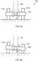
FIG. 2a is a schematic front view of a known landing gear assembly in which two wheels are mounted on a common axle; -
FIG. 2b illustrates the landing gear assembly ofFIG. 2a with a deflated tyre; -
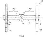
FIG. 3 is a longitudinal cross section diagram of an aircraft landing gear assembly according to an embodiment of the present invention; -
FIG. 4 is a longitudinal cross section diagram of an aircraft landing gear assembly according to an embodiment of the present invention; -
FIG. 5 is a longitudinal cross section diagram of an aircraft landing gear assembly according to an embodiment of the present invention; and -
FIG. 6 is a schematic diagram illustrating a bottom end of a strut which can carry the landing gear assembly ofFIG. 5 . -
FIG. 1a illustrates a known aircraft landing gear assembly generally at 100. - The
landing gear assembly 100 includes amain strut 102 which is movably coupled to an aircraft (not shown). Abogie beam 104 is pivotally mounted at a lower end of themain strut 102 via apivot pin 106. At one end, or front, of thebogie beam 104 there is mounted awheel assembly 112 onaxle 108. At the other end, or back, of thebogie beam 104 there is mounted asecond wheel assembly 114 via asecond axle 110. Each wheel assembly can incorporate a brake assembly. -
FIG. 1b shows the landing gear assembly ofFIG. 1a with a deflatedrear tyre 114. As can be seen, thebogie beam 104 has rotated relative to thestrut 102 to account for the difference in rolling radius due to the deflatedtyre 114. - However, as illustrated in
FIG.s 2a and 2b , in the case of landing gear assemblies in which a pair ofwheel assemblies common axle 108, and onewheel 112b deflates, thebogie beam 104 cannot pivot to account for the deflatedtyre 112b because the end region of thebogie beam 104 adjacent theaxle 108 is supported by theinflated tyre 112a. This results in flexure of the landing gear components including theaxle 108,bogie beam 104 andstrut 102. Consequently, these components must be of sufficient size and/or strength to withstand such loading. Other components of the landing gear also need to be sized to deal with the increased load on them i.e. the full load taken on three tyres, or the full load taken on two tyres. - The present inventor has identified that the weight of known landing gear can be reduced by designing a landing gear assembly in which the bogie beam assembly is arranged to place a wheel rim of a wheel assembly in contact with the ground in the event of a tyre of the wheel assembly deflating. As such, the landing gear can be designed for the full load distributed evenly across four loading points (tyre or wheel rim).
-
FIG. 3 is a diagram of part of an aircraft; more specifically, an aircraft landing gear assembly 10 according to an embodiment of the invention. The landing gear assembly 10 is shown in cross section through the longitudinal axis of thebogie beam 12. - The
bogie beam 12 is generally of conventional construction in that it includes a central pivot bearing 14 by which it can be pivotally connected to an aircraft landing gear main strut (not shown), such as a rigid strut or a shock absorbing strut, so as to pivot about a bogie pivot axis M. - At a first end, the
bogie 12 includesaxle mounting bushes 16 in which afirst axle 18 is mounted. A second end of thebogie 12 also includesaxle mounting bushes 16 via which asecond axle 20 is mounted. The longitudinal axis B of thefirst axle 18 is parallel with respect to the longitudinal axis B of thesecond axle 20. - The aircraft landing gear assembly 10 of the illustrated embodiment differs from a conventional aircraft landing gear assembly in that it includes flexure zones FZ1, FZ2.
- The first flexure zone FZ1 is located between the bogie pivot bearing 14 and the
first axle 18. It encompasses a majority of the length of thebogie beam 12 between these two items. However, in other embodiments the flexure zone can be defined by the entirety of the distance between the bogie pivot bearing 14 and thefirst axle 18, or the flexure zone FZ1 can be defined by less than half the distance between these two items. - Similarly, the second flexure zone FZ2 is located on the other side of the
bogie beam 12 between the bogie pivot bearing 14 and thesecond axle 20. Otherwise, the second flexure zone FZ2 can be identical to the first flexure zone FZ1. - The flexure zones FZ1, FZ2 are arranged to permit the
axles bogie beam 12 can flex to allow the axle to rotate sufficiently to place the deflated wheel assembly in contact with the ground, meaning that each wheel is equally loaded despite the deflated tyre(s). For a wheel assembly with a deflated tyre, the load can be supported by the wheel rim. - The present inventor found a
bogie beam 12 with flexure zones FZ1, FZ2 of box section, or open section, such as C or I section, can provide the required degree of flexure in the event of a tyre deflation. Suitable geometries can be determined using routine testing. -
FIG. 4 shows an aircraft landing gear assembly according to a further embodiment of the invention generally at 30. The aircraftlanding gear assembly 30 is similar to the aircraft landing gear 10 according to the previous embodiment and like parts have been given like reference numerals. For brevity, the following description will focus on the differences. - The aircraft
landing gear assembly 30 of the present embodiment is configured to enable theaxles rotatable end sections - More specifically, the
bogie beam 32 comprises amain body portion 32 which hascylindrical end bearings end bearings second end bosses end bosses bogie body 32 about the longitudinal axis L. Thebosses axle mounting bushes 16 arranged to mount the first and second axles, 18, 20 in the conventional manner. - In the event of a tyre on an axle deflating, the boss and axle can rotate together relative to the bogie beam in order to place the rim of the deflated wheel assembly in contact with the ground, thereby equalising loading on the wheel.
- Means can be provided to maintain the orientation of the
axles - Thus, both of the above-identified embodiments of the invention include a bogie beam which is arranged to permit the axles to rotate relative to the central portion of the encompassing the bogie pivot axis in the event of tyre deflation.
-
FIG. 5 shows an aircraftlanding gear assembly 40 according to a further embodiment of the invention. Thelanding gear assembly 40 includes first andsecond bogie beams identical pivot bearings bogie beams - At a first end, the
first bogie beam 42a includes aconventional mounting bushing 46a by which afirst axle half 50a is mounted. Thesecond bogie beam 42b includes a corresponding mountingbushing 46b which carries athird axle half 50b. The first andthird axle halves bogie beams - Similarly, a second end of the
first bogie beam 42a includes aconventional mounting bushing 46a which mounts asecond axle half 48a and the second 42b includes a conventional mounting bushing 26b which mounts afourth axle half 48b. - Each
axle half - Therefore, in the event of the tyre of a wheel assembly mounted on the
first axle half 50a deflating, thefirst bogie 42a can rotate about the bogie pivot axis M independently of thesecond bogie 42b so as to place the rim of the deflated wheel assembly in contact with the ground. Likewise for any of the other wheel assemblies. - While the arrangement of the
landing gear assembly 40 reduces the amount of flexure required by components of the aircraft landing gear in order to account for the deflated tyre, it does not substantially eliminate such flexure. - Therefore, and referring additionally to
FIG. 6 , thestrut 52 can comprise anupper strut portion 54 arranged to be movably coupled to an aircraft (not shown) and abogie mounting formation 58 connected to theupper portion 54 via a multi-axis joint 56, such as a spherical joint. Thebogie mounting formation 58 can include afirst axle portion 60a arranged to mount thefirst bogie beam 42a, and a second, coaxial,axle 60b arranged to mount thesecond bogie beam 42b. Thus, thebogie mounting formation 58 can move relative to theupper strut portion 54 in a lateral direction to substantially isolate the remaining components of the landing gear assembly from loads that would otherwise be imparted due to tyre deflation. - In any embodiment, it is preferred that the bogie beam is arranged to enable the first and second axles to each pivot relative to the mounting formation about the longitudinal axis of the bogie beam by at least 8° and in some embodiments at least 10° or 12°. The degree of pivoting required depends on the ratio of tyre rolling radius to wheel rim radius and the spacing between the two wheel assemblies on the axle. In one example, a wheel assembly may have a rolling radius of approximately 0.65m, a wheel rim radius of approximately 0.36m and a spacing of approximately 1.4m centre to centre between wheel assemblies on an axle, meaning that one flat tyre would require an angle of approximately 12° to place the wheel rim in contact with the ground in the event of the tyre fully deflating. In another example, a wheel assembly may have a rolling radius of approximately 0.65m, a wheel rim radius of approximately 0.36m and a spacing of approximately 1.74m centre to centre between wheel assemblies on an axle, meaning that one flat tyre would require an angle of approximately 9.6° to place the wheel rim in contact with the ground in the event of the tyre fully deflating.
- Landing gear assemblies according to embodiments of the invention can be formed of conventional aerospace materials, such as stainless steel, aluminium or titanium. Certain components such as the bogie beam can be formed from fibre reinforced composite material.
- Landing gear assemblies according to embodiments of the invention can be main landing gear assemblies for medium to large aircrafts.
- Although the invention has been described above with reference to one or more preferred embodiments, it will be appreciated that various changes or modifications can be made without departing from the scope of the invention as defined in the appended claims. The word "comprising" can mean "including" or "consisting of" and therefore does not exclude the presence of elements or steps other than those listed in any claim or the specification as a whole. The mere fact that certain measures are recited in mutually different dependent claims does not indicate that a combination of these measures cannot be used to advantage.
- Before setting out the claims, we will first present a set of clauses defining embodiments of the invention.
- Clause 1. An aircraft landing gear assembly (10, 30) comprising:
- an elongate bogie beam (12, 32) including a bearing (14) via which the bogie beam is arranged to be movably mounted to an aircraft landing gear main strut, first and second end regions, a first longitudinal axis (L) extending between the bearing and the first end region and a second longitudinal axis (L) extending between the bearing and the second end region;
- a first axle (18) mounted at a first end region of the bogie beam, the first axle defining a first wheel mounting portion on a first side of the bogie beam for supporting a first wheel assembly and a second wheel mounting portion on a second side of the bogie beam for supporting a second wheel assembly;
- a second axle (20) mounted at a second end region of the bogie beam, with the bearing between the first and second end regions, the second axle defining a third wheel mounting portion on the first side of the bogie beam for supporting a third wheel assembly and a fourth wheel mounting portion on the second side of the bogie beam for supporting a fourth wheel assembly,
- wherein the bogie beam is arranged to enable the first and second axles to each pivot relative to the bearing about the respective longitudinal axis of the bogie beam by an amount which is sufficient to place a wheel rim of a wheel assembly in contact with the ground in the event of a tyre of the wheel assembly deflating.
-
Clause 2. An aircraft landing gear assembly according to clause 1, wherein the bogie beam is arranged to enable the first and second axles to each pivot relative to the bearing about the longitudinal axis of the bogie beam by at least 8°. - Clause 3. An aircraft landing gear assembly according to any preceding clause, wherein the bearing of the bogie beam is a circular bearing arranged to pivotally couple the bogie beam to the main strut via a pivot pin.
- Clause 4. An aircraft landing gear assembly according to any preceding clause, wherein the first longitudinal axis is coaxial with respect to the second longitudinal axis.
- Clause 5. An aircraft landing gear assembly (10) according to any preceding clause, wherein the bogie beam is arranged to enable the first and second axles to each pivot relative to the bearing about the longitudinal axis of the bogie beam by virtue of first and second flexure zones (FZ1, FZ2) of the bogie beam, the first flexure zone being located between the bearing and the first axle and the second flexure zone being located between the bearing and the second axle.
- Clause 6. An aircraft landing gear assembly according to clause 5, wherein the flexure zones each comprise a portion of the bogie beam which has a box section, C section or I section profile.
- Clause 7. An aircraft landing gear assembly according to clause 5 or clause 6, wherein the flexure zones each occupy a majority of the length of the bogie beam between the bearing and the respective axle.
- Clause 8. An aircraft landing gear assembly (30) according to any of clauses 1 to 4, wherein the bogie beam comprises a central body portion (32) which includes the bearing and a pair rotatable mounted end bosses (34, 36) which support the axles, the bogie beam being arranged to enable the first and second axles to each pivot relative to the bearing about the longitudinal axis of the bogie beam by virtue of the end bosses.
- Clause 9. An aircraft landing gear assembly (40) comprising:
- a first elongate bogie beam (42a) including a first bearing (44a) via which the first bogie beam is arranged to be pivotally mounted to an aircraft landing gear main strut and defining a first bogie pivot axis;
- a second elongate bogie beam (42b) including a second bearing (44b), defining a second bogie pivot axis, via which the second bogie beam is arranged to be pivotally mounted to the aircraft landing gear main strut in a side by side adjacent relationship with the first bogie pivot axis being coaxial with respect to the second bogie pivot axis;
- a first axle (50a) mounted at a first end region of the first bogie beam, the first axle defining a first wheel mounting portion on a first side of the first bogie beam for supporting a first wheel assembly;
- a second axle (48a) mounted at a second end region of the first bogie beam, the second axle defining a second wheel mounting portion on the first side of the first bogie beam for supporting a second wheel assembly;
- a third axle (50b) mounted at a first end region of the second bogie beam, the third axle defining a third wheel mounting portion on a second side of the second bogie beam for supporting a first wheel assembly, the second side facing away from the first bogie beam; and
- a fourth axle (48b) mounted at a second end region of the second bogie beam, the fourth axle defining a fourth wheel mounting portion on the second side of the bogie beam for supporting a fourth wheel assembly,
- such that the first and second bogie beams can independently pivot about the respective bogie pivot axes in order to place a wheel rim of a wheel assembly in contact with the ground in the event of a tyre of the wheel assembly deflating.
- Clause 10. An aircraft landing gear assembly according to clause 9, further comprising the aircraft landing gear main strut (52), the main strut comprising:
- a body portion (54) including a main aircraft coupling via which the main strut is arranged to be movably coupled to an aircraft;
- a bogie mounting portion (58) including a first axle portion arranged to pivotally mount the first bogie beam via the first bearing and a second axle portion arranged to pivotally mount the second bogie beam via the second bearing; and
- a flexible or dynamic bearing region (56) connecting the body portion to the bogie mounting portion for pivotal movement between them.
- Clause 11. An aircraft landing gear assembly according to clause 10, wherein the flexible or dynamic bearing region comprises a spherical bearing.
-
Clause 12. An aircraft including one or more aircraft landing gear assemblies according to any preceding clause.
Claims (4)
- An aircraft landing gear assembly (40) comprising:a first elongate bogie beam (42a) including a first bearing (44a) via which the first bogie beam is arranged to be pivotally mounted to an aircraft landing gear main strut and defining a first bogie pivot axis;a second elongate bogie beam (42b) including a second bearing (44b), defining a second bogie pivot axis, via which the second bogie beam is arranged to be pivotally mounted to the aircraft landing gear main strut in a side by side adjacent relationship with the first bogie pivot axis being coaxial with respect to the second bogie pivot axis;a first axle (50a) mounted at a first end region of the first bogie beam, the first axle defining a first wheel mounting portion on a first side of the first bogie beam for supporting a first wheel assembly;a second axle (48a) mounted at a second end region of the first bogie beam, the second axle defining a second wheel mounting portion on the first side of the first bogie beam for supporting a second wheel assembly;a third axle (50b) mounted at a first end region of the second bogie beam, the third axle defining a third wheel mounting portion on a second side of the second bogie beam for supporting a first wheel assembly, the second side facing away from the first bogie beam; anda fourth axle (48b) mounted at a second end region of the second bogie beam, the fourth axle defining a fourth wheel mounting portion on the second side of the bogie beam for supporting a fourth wheel assembly,such that the first and second bogie beams can independently pivot about the respective bogie pivot axes in order to place a wheel rim of a wheel assembly in contact with the ground in the event of a tyre of the wheel assembly deflating.
- An aircraft landing gear assembly according to claim 1, further comprising the aircraft landing gear main strut (52), the main strut comprising:a body portion (54) including a main aircraft coupling via which the main strut is arranged to be movably coupled to an aircraft;a bogie mounting portion (58) including a first axle portion arranged to pivotally mount the first bogie beam via the first bearing and a second axle portion arranged to pivotally mount the second bogie beam via the second bearing; anda flexible or dynamic bearing region (56) connecting the body portion to the bogie mounting portion for pivotal movement between them.
- An aircraft landing gear assembly according to claim 2, wherein the flexible or dynamic bearing region comprises a spherical bearing.
- An aircraft including one or more aircraft landing gear assemblies according to any preceding claim.
Priority Applications (1)
| Application Number | Priority Date | Filing Date | Title |
|---|---|---|---|
| EP20213970.5A EP3828079B1 (en) | 2017-04-20 | 2017-04-20 | Aircraft landing gear assembly |
Applications Claiming Priority (2)
| Application Number | Priority Date | Filing Date | Title |
|---|---|---|---|
| EP20213970.5A EP3828079B1 (en) | 2017-04-20 | 2017-04-20 | Aircraft landing gear assembly |
| EP17167354.4A EP3392138B1 (en) | 2017-04-20 | 2017-04-20 | Aircraft landing gear assembly |
Related Parent Applications (2)
| Application Number | Title | Priority Date | Filing Date |
|---|---|---|---|
| EP17167354.4A Division EP3392138B1 (en) | 2017-04-20 | 2017-04-20 | Aircraft landing gear assembly |
| EP17167354.4A Division-Into EP3392138B1 (en) | 2017-04-20 | 2017-04-20 | Aircraft landing gear assembly |
Publications (2)
| Publication Number | Publication Date |
|---|---|
| EP3828079A1 true EP3828079A1 (en) | 2021-06-02 |
| EP3828079B1 EP3828079B1 (en) | 2023-10-11 |
Family
ID=58579093
Family Applications (2)
| Application Number | Title | Priority Date | Filing Date |
|---|---|---|---|
| EP17167354.4A Active EP3392138B1 (en) | 2017-04-20 | 2017-04-20 | Aircraft landing gear assembly |
| EP20213970.5A Active EP3828079B1 (en) | 2017-04-20 | 2017-04-20 | Aircraft landing gear assembly |
Family Applications Before (1)
| Application Number | Title | Priority Date | Filing Date |
|---|---|---|---|
| EP17167354.4A Active EP3392138B1 (en) | 2017-04-20 | 2017-04-20 | Aircraft landing gear assembly |
Country Status (4)
| Country | Link |
|---|---|
| US (2) | US10829209B2 (en) |
| EP (2) | EP3392138B1 (en) |
| CN (1) | CN108725759B (en) |
| CA (2) | CA3001985C (en) |
Families Citing this family (2)
| Publication number | Priority date | Publication date | Assignee | Title |
|---|---|---|---|---|
| CA2972498C (en) * | 2017-06-28 | 2024-01-23 | Bombardier Inc. | Takeoff pitch guidance system and method |
| WO2026061605A1 (en) * | 2024-09-17 | 2026-03-26 | Safran Landing Systems | Landing gear with adjustable tire camber |
Citations (6)
| Publication number | Priority date | Publication date | Assignee | Title |
|---|---|---|---|---|
| DE728620C (en) * | 1939-05-17 | 1942-11-30 | Ver Deutsche Metallwerke Ag | The wheel carrier is arranged approximately vertically on the aircraft and has twin wheels lying next to each other |
| FR898049A (en) * | 1943-01-09 | 1945-04-09 | Messerschmitt Ag | Twin wheel device for airplanes, mounted on a common rotating or fixed axle |
| EP0492687A1 (en) * | 1990-12-20 | 1992-07-01 | The Boeing Company | Landing gear truck with wheel load equalization |
| FR2699885A1 (en) * | 1992-12-28 | 1994-07-01 | Messier Bugatti | Lifting landing gear for large aircraft. |
| US5947414A (en) * | 1994-03-17 | 1999-09-07 | The Boeing Company | Main landing gear having tilting of main gear pivot pins |
| FR2953806A1 (en) * | 2009-12-11 | 2011-06-17 | Eurocopter France | LANDING TRAIN FOR AIRCRAFT, SWING WITH PIVOT AND ARTICULATED DIABOLO |
Family Cites Families (3)
| Publication number | Priority date | Publication date | Assignee | Title |
|---|---|---|---|---|
| US6123292A (en) * | 1994-03-17 | 2000-09-26 | The Boeing Company | Main landing gear having independent steering of each axle on multiple axle trucks |
| JP2001080504A (en) * | 1999-09-17 | 2001-03-27 | Railway Technical Res Inst | Leg device with wheel lifting function |
| GB2489054B (en) * | 2011-04-13 | 2013-08-07 | Messier Dowty Ltd | Aircraft landing gear |
-
2017
- 2017-04-20 EP EP17167354.4A patent/EP3392138B1/en active Active
- 2017-04-20 EP EP20213970.5A patent/EP3828079B1/en active Active
-
2018
- 2018-04-17 CA CA3001985A patent/CA3001985C/en active Active
- 2018-04-17 CA CA3250333A patent/CA3250333A1/en active Pending
- 2018-04-18 US US15/955,910 patent/US10829209B2/en active Active
- 2018-04-19 CN CN201810353653.6A patent/CN108725759B/en active Active
-
2020
- 2020-09-30 US US17/038,956 patent/US11643193B2/en active Active
Patent Citations (6)
| Publication number | Priority date | Publication date | Assignee | Title |
|---|---|---|---|---|
| DE728620C (en) * | 1939-05-17 | 1942-11-30 | Ver Deutsche Metallwerke Ag | The wheel carrier is arranged approximately vertically on the aircraft and has twin wheels lying next to each other |
| FR898049A (en) * | 1943-01-09 | 1945-04-09 | Messerschmitt Ag | Twin wheel device for airplanes, mounted on a common rotating or fixed axle |
| EP0492687A1 (en) * | 1990-12-20 | 1992-07-01 | The Boeing Company | Landing gear truck with wheel load equalization |
| FR2699885A1 (en) * | 1992-12-28 | 1994-07-01 | Messier Bugatti | Lifting landing gear for large aircraft. |
| US5947414A (en) * | 1994-03-17 | 1999-09-07 | The Boeing Company | Main landing gear having tilting of main gear pivot pins |
| FR2953806A1 (en) * | 2009-12-11 | 2011-06-17 | Eurocopter France | LANDING TRAIN FOR AIRCRAFT, SWING WITH PIVOT AND ARTICULATED DIABOLO |
Also Published As
| Publication number | Publication date |
|---|---|
| US20180305000A1 (en) | 2018-10-25 |
| CA3250333A1 (en) | 2025-07-09 |
| CN108725759B (en) | 2023-05-16 |
| CA3001985C (en) | 2025-10-07 |
| CA3001985A1 (en) | 2018-10-20 |
| CN108725759A (en) | 2018-11-02 |
| US10829209B2 (en) | 2020-11-10 |
| EP3392138B1 (en) | 2021-03-17 |
| US20210009258A1 (en) | 2021-01-14 |
| EP3392138A1 (en) | 2018-10-24 |
| EP3828079B1 (en) | 2023-10-11 |
| US11643193B2 (en) | 2023-05-09 |
Similar Documents
| Publication | Publication Date | Title |
|---|---|---|
| US3572745A (en) | Multiple axle suspension | |
| US11059571B2 (en) | Aircraft landing gear assembly | |
| US3856325A (en) | Multiple axle vehicle suspension system | |
| EP1615788B1 (en) | Wheel suspension for vehicles | |
| US11643193B2 (en) | Aircraft landing gear assembly | |
| US11292447B2 (en) | Configuration of landing gear assemblies for an aircraft | |
| US6123292A (en) | Main landing gear having independent steering of each axle on multiple axle trucks | |
| MX2015002680A (en) | Transom for a railway car truck. | |
| MXPA04011365A (en) | Multi-piece axle and suspension. | |
| US5743491A (en) | Very large aircraft landing gear having eight wheel truck | |
| US20220185369A1 (en) | Knuckle for a self-steering axle/suspension system | |
| CA2921836C (en) | Aircraft landing gear assembly | |
| US7413039B2 (en) | Heavy vehicle | |
| US2241193A (en) | Dual wheel and brake construction | |
| US11433992B2 (en) | Rotorcraft having at least one undercarriage with at least one inclined wheel, and a method | |
| US2910014A (en) | Suspension system saddle support | |
| US2912234A (en) | Suspension system air spring | |
| EP3992053A1 (en) | Bogie for a rail vehicle and rail vehicle with a bogie | |
| EP3279084B1 (en) | Aircraft landing gear assembly | |
| IT202300021480A1 (en) | LOAD BALANCING SYSTEM ON THE PLATFORMS OF GENERAL TRANSPORT MEANS | |
| GB2592204A (en) | Modular landing gear |
Legal Events
| Date | Code | Title | Description |
|---|---|---|---|
| PUAI | Public reference made under article 153(3) epc to a published international application that has entered the european phase |
Free format text: ORIGINAL CODE: 0009012 |
|
| STAA | Information on the status of an ep patent application or granted ep patent |
Free format text: STATUS: REQUEST FOR EXAMINATION WAS MADE |
|
| 17P | Request for examination filed |
Effective date: 20201215 |
|
| AC | Divisional application: reference to earlier application |
Ref document number: 3392138 Country of ref document: EP Kind code of ref document: P |
|
| AK | Designated contracting states |
Kind code of ref document: A1 Designated state(s): AL AT BE BG CH CY CZ DE DK EE ES FI FR GB GR HR HU IE IS IT LI LT LU LV MC MK MT NL NO PL PT RO RS SE SI SK SM TR |
|
| STAA | Information on the status of an ep patent application or granted ep patent |
Free format text: STATUS: EXAMINATION IS IN PROGRESS |
|
| 17Q | First examination report despatched |
Effective date: 20220810 |
|
| GRAP | Despatch of communication of intention to grant a patent |
Free format text: ORIGINAL CODE: EPIDOSNIGR1 |
|
| STAA | Information on the status of an ep patent application or granted ep patent |
Free format text: STATUS: GRANT OF PATENT IS INTENDED |
|
| INTG | Intention to grant announced |
Effective date: 20230713 |
|
| GRAS | Grant fee paid |
Free format text: ORIGINAL CODE: EPIDOSNIGR3 |
|
| GRAA | (expected) grant |
Free format text: ORIGINAL CODE: 0009210 |
|
| STAA | Information on the status of an ep patent application or granted ep patent |
Free format text: STATUS: THE PATENT HAS BEEN GRANTED |
|
| AC | Divisional application: reference to earlier application |
Ref document number: 3392138 Country of ref document: EP Kind code of ref document: P |
|
| AK | Designated contracting states |
Kind code of ref document: B1 Designated state(s): AL AT BE BG CH CY CZ DE DK EE ES FI FR GB GR HR HU IE IS IT LI LT LU LV MC MK MT NL NO PL PT RO RS SE SI SK SM TR |
|
| REG | Reference to a national code |
Ref country code: GB Ref legal event code: FG4D |
|
| REG | Reference to a national code |
Ref country code: CH Ref legal event code: EP |
|
| REG | Reference to a national code |
Ref country code: DE Ref legal event code: R096 Ref document number: 602017075369 Country of ref document: DE |
|
| REG | Reference to a national code |
Ref country code: IE Ref legal event code: FG4D |
|
| REG | Reference to a national code |
Ref country code: LT Ref legal event code: MG9D |
|
| REG | Reference to a national code |
Ref country code: NL Ref legal event code: MP Effective date: 20231011 |
|
| REG | Reference to a national code |
Ref country code: AT Ref legal event code: MK05 Ref document number: 1619997 Country of ref document: AT Kind code of ref document: T Effective date: 20231011 |
|
| PG25 | Lapsed in a contracting state [announced via postgrant information from national office to epo] |
Ref country code: NL Free format text: LAPSE BECAUSE OF FAILURE TO SUBMIT A TRANSLATION OF THE DESCRIPTION OR TO PAY THE FEE WITHIN THE PRESCRIBED TIME-LIMIT Effective date: 20231011 |
|
| PG25 | Lapsed in a contracting state [announced via postgrant information from national office to epo] |
Ref country code: GR Free format text: LAPSE BECAUSE OF FAILURE TO SUBMIT A TRANSLATION OF THE DESCRIPTION OR TO PAY THE FEE WITHIN THE PRESCRIBED TIME-LIMIT Effective date: 20240112 |
|
| PG25 | Lapsed in a contracting state [announced via postgrant information from national office to epo] |
Ref country code: IS Free format text: LAPSE BECAUSE OF FAILURE TO SUBMIT A TRANSLATION OF THE DESCRIPTION OR TO PAY THE FEE WITHIN THE PRESCRIBED TIME-LIMIT Effective date: 20240211 |
|
| PG25 | Lapsed in a contracting state [announced via postgrant information from national office to epo] |
Ref country code: LT Free format text: LAPSE BECAUSE OF FAILURE TO SUBMIT A TRANSLATION OF THE DESCRIPTION OR TO PAY THE FEE WITHIN THE PRESCRIBED TIME-LIMIT Effective date: 20231011 |
|
| PG25 | Lapsed in a contracting state [announced via postgrant information from national office to epo] |
Ref country code: AT Free format text: LAPSE BECAUSE OF FAILURE TO SUBMIT A TRANSLATION OF THE DESCRIPTION OR TO PAY THE FEE WITHIN THE PRESCRIBED TIME-LIMIT Effective date: 20231011 |
|
| PG25 | Lapsed in a contracting state [announced via postgrant information from national office to epo] |
Ref country code: ES Free format text: LAPSE BECAUSE OF FAILURE TO SUBMIT A TRANSLATION OF THE DESCRIPTION OR TO PAY THE FEE WITHIN THE PRESCRIBED TIME-LIMIT Effective date: 20231011 |
|
| PG25 | Lapsed in a contracting state [announced via postgrant information from national office to epo] |
Ref country code: LT Free format text: LAPSE BECAUSE OF FAILURE TO SUBMIT A TRANSLATION OF THE DESCRIPTION OR TO PAY THE FEE WITHIN THE PRESCRIBED TIME-LIMIT Effective date: 20231011 Ref country code: IS Free format text: LAPSE BECAUSE OF FAILURE TO SUBMIT A TRANSLATION OF THE DESCRIPTION OR TO PAY THE FEE WITHIN THE PRESCRIBED TIME-LIMIT Effective date: 20240211 Ref country code: GR Free format text: LAPSE BECAUSE OF FAILURE TO SUBMIT A TRANSLATION OF THE DESCRIPTION OR TO PAY THE FEE WITHIN THE PRESCRIBED TIME-LIMIT Effective date: 20240112 Ref country code: ES Free format text: LAPSE BECAUSE OF FAILURE TO SUBMIT A TRANSLATION OF THE DESCRIPTION OR TO PAY THE FEE WITHIN THE PRESCRIBED TIME-LIMIT Effective date: 20231011 Ref country code: BG Free format text: LAPSE BECAUSE OF FAILURE TO SUBMIT A TRANSLATION OF THE DESCRIPTION OR TO PAY THE FEE WITHIN THE PRESCRIBED TIME-LIMIT Effective date: 20240111 Ref country code: AT Free format text: LAPSE BECAUSE OF FAILURE TO SUBMIT A TRANSLATION OF THE DESCRIPTION OR TO PAY THE FEE WITHIN THE PRESCRIBED TIME-LIMIT Effective date: 20231011 Ref country code: PT Free format text: LAPSE BECAUSE OF FAILURE TO SUBMIT A TRANSLATION OF THE DESCRIPTION OR TO PAY THE FEE WITHIN THE PRESCRIBED TIME-LIMIT Effective date: 20240212 |
|
| PG25 | Lapsed in a contracting state [announced via postgrant information from national office to epo] |
Ref country code: SE Free format text: LAPSE BECAUSE OF FAILURE TO SUBMIT A TRANSLATION OF THE DESCRIPTION OR TO PAY THE FEE WITHIN THE PRESCRIBED TIME-LIMIT Effective date: 20231011 Ref country code: RS Free format text: LAPSE BECAUSE OF FAILURE TO SUBMIT A TRANSLATION OF THE DESCRIPTION OR TO PAY THE FEE WITHIN THE PRESCRIBED TIME-LIMIT Effective date: 20231011 Ref country code: PL Free format text: LAPSE BECAUSE OF FAILURE TO SUBMIT A TRANSLATION OF THE DESCRIPTION OR TO PAY THE FEE WITHIN THE PRESCRIBED TIME-LIMIT Effective date: 20231011 Ref country code: NO Free format text: LAPSE BECAUSE OF FAILURE TO SUBMIT A TRANSLATION OF THE DESCRIPTION OR TO PAY THE FEE WITHIN THE PRESCRIBED TIME-LIMIT Effective date: 20240111 Ref country code: LV Free format text: LAPSE BECAUSE OF FAILURE TO SUBMIT A TRANSLATION OF THE DESCRIPTION OR TO PAY THE FEE WITHIN THE PRESCRIBED TIME-LIMIT Effective date: 20231011 Ref country code: HR Free format text: LAPSE BECAUSE OF FAILURE TO SUBMIT A TRANSLATION OF THE DESCRIPTION OR TO PAY THE FEE WITHIN THE PRESCRIBED TIME-LIMIT Effective date: 20231011 |
|
| PG25 | Lapsed in a contracting state [announced via postgrant information from national office to epo] |
Ref country code: DK Free format text: LAPSE BECAUSE OF FAILURE TO SUBMIT A TRANSLATION OF THE DESCRIPTION OR TO PAY THE FEE WITHIN THE PRESCRIBED TIME-LIMIT Effective date: 20231011 |
|
| REG | Reference to a national code |
Ref country code: DE Ref legal event code: R097 Ref document number: 602017075369 Country of ref document: DE |
|
| PG25 | Lapsed in a contracting state [announced via postgrant information from national office to epo] |
Ref country code: CZ Free format text: LAPSE BECAUSE OF FAILURE TO SUBMIT A TRANSLATION OF THE DESCRIPTION OR TO PAY THE FEE WITHIN THE PRESCRIBED TIME-LIMIT Effective date: 20231011 |
|
| PG25 | Lapsed in a contracting state [announced via postgrant information from national office to epo] |
Ref country code: SK Free format text: LAPSE BECAUSE OF FAILURE TO SUBMIT A TRANSLATION OF THE DESCRIPTION OR TO PAY THE FEE WITHIN THE PRESCRIBED TIME-LIMIT Effective date: 20231011 |
|
| PG25 | Lapsed in a contracting state [announced via postgrant information from national office to epo] |
Ref country code: SM Free format text: LAPSE BECAUSE OF FAILURE TO SUBMIT A TRANSLATION OF THE DESCRIPTION OR TO PAY THE FEE WITHIN THE PRESCRIBED TIME-LIMIT Effective date: 20231011 Ref country code: SK Free format text: LAPSE BECAUSE OF FAILURE TO SUBMIT A TRANSLATION OF THE DESCRIPTION OR TO PAY THE FEE WITHIN THE PRESCRIBED TIME-LIMIT Effective date: 20231011 Ref country code: RO Free format text: LAPSE BECAUSE OF FAILURE TO SUBMIT A TRANSLATION OF THE DESCRIPTION OR TO PAY THE FEE WITHIN THE PRESCRIBED TIME-LIMIT Effective date: 20231011 Ref country code: IT Free format text: LAPSE BECAUSE OF FAILURE TO SUBMIT A TRANSLATION OF THE DESCRIPTION OR TO PAY THE FEE WITHIN THE PRESCRIBED TIME-LIMIT Effective date: 20231011 Ref country code: EE Free format text: LAPSE BECAUSE OF FAILURE TO SUBMIT A TRANSLATION OF THE DESCRIPTION OR TO PAY THE FEE WITHIN THE PRESCRIBED TIME-LIMIT Effective date: 20231011 Ref country code: DK Free format text: LAPSE BECAUSE OF FAILURE TO SUBMIT A TRANSLATION OF THE DESCRIPTION OR TO PAY THE FEE WITHIN THE PRESCRIBED TIME-LIMIT Effective date: 20231011 Ref country code: CZ Free format text: LAPSE BECAUSE OF FAILURE TO SUBMIT A TRANSLATION OF THE DESCRIPTION OR TO PAY THE FEE WITHIN THE PRESCRIBED TIME-LIMIT Effective date: 20231011 |
|
| PLBE | No opposition filed within time limit |
Free format text: ORIGINAL CODE: 0009261 |
|
| STAA | Information on the status of an ep patent application or granted ep patent |
Free format text: STATUS: NO OPPOSITION FILED WITHIN TIME LIMIT |
|
| 26N | No opposition filed |
Effective date: 20240712 |
|
| PG25 | Lapsed in a contracting state [announced via postgrant information from national office to epo] |
Ref country code: SI Free format text: LAPSE BECAUSE OF FAILURE TO SUBMIT A TRANSLATION OF THE DESCRIPTION OR TO PAY THE FEE WITHIN THE PRESCRIBED TIME-LIMIT Effective date: 20231011 |
|
| PG25 | Lapsed in a contracting state [announced via postgrant information from national office to epo] |
Ref country code: SI Free format text: LAPSE BECAUSE OF FAILURE TO SUBMIT A TRANSLATION OF THE DESCRIPTION OR TO PAY THE FEE WITHIN THE PRESCRIBED TIME-LIMIT Effective date: 20231011 |
|
| PG25 | Lapsed in a contracting state [announced via postgrant information from national office to epo] |
Ref country code: MC Free format text: LAPSE BECAUSE OF FAILURE TO SUBMIT A TRANSLATION OF THE DESCRIPTION OR TO PAY THE FEE WITHIN THE PRESCRIBED TIME-LIMIT Effective date: 20231011 |
|
| PG25 | Lapsed in a contracting state [announced via postgrant information from national office to epo] |
Ref country code: MC Free format text: LAPSE BECAUSE OF FAILURE TO SUBMIT A TRANSLATION OF THE DESCRIPTION OR TO PAY THE FEE WITHIN THE PRESCRIBED TIME-LIMIT Effective date: 20231011 |
|
| REG | Reference to a national code |
Ref country code: CH Ref legal event code: PL |
|
| PG25 | Lapsed in a contracting state [announced via postgrant information from national office to epo] |
Ref country code: LU Free format text: LAPSE BECAUSE OF NON-PAYMENT OF DUE FEES Effective date: 20240420 |
|
| REG | Reference to a national code |
Ref country code: BE Ref legal event code: MM Effective date: 20240430 |
|
| PG25 | Lapsed in a contracting state [announced via postgrant information from national office to epo] |
Ref country code: LU Free format text: LAPSE BECAUSE OF NON-PAYMENT OF DUE FEES Effective date: 20240420 |
|
| PG25 | Lapsed in a contracting state [announced via postgrant information from national office to epo] |
Ref country code: BE Free format text: LAPSE BECAUSE OF NON-PAYMENT OF DUE FEES Effective date: 20240430 |
|
| PG25 | Lapsed in a contracting state [announced via postgrant information from national office to epo] |
Ref country code: BE Free format text: LAPSE BECAUSE OF NON-PAYMENT OF DUE FEES Effective date: 20240430 Ref country code: CH Free format text: LAPSE BECAUSE OF NON-PAYMENT OF DUE FEES Effective date: 20240430 |
|
| PG25 | Lapsed in a contracting state [announced via postgrant information from national office to epo] |
Ref country code: IE Free format text: LAPSE BECAUSE OF NON-PAYMENT OF DUE FEES Effective date: 20240420 |
|
| PGFP | Annual fee paid to national office [announced via postgrant information from national office to epo] |
Ref country code: DE Payment date: 20250417 Year of fee payment: 9 |
|
| PGFP | Annual fee paid to national office [announced via postgrant information from national office to epo] |
Ref country code: FR Payment date: 20250428 Year of fee payment: 9 |
|
| PG25 | Lapsed in a contracting state [announced via postgrant information from national office to epo] |
Ref country code: CY Free format text: LAPSE BECAUSE OF FAILURE TO SUBMIT A TRANSLATION OF THE DESCRIPTION OR TO PAY THE FEE WITHIN THE PRESCRIBED TIME-LIMIT; INVALID AB INITIO Effective date: 20170420 |
|
| PG25 | Lapsed in a contracting state [announced via postgrant information from national office to epo] |
Ref country code: HU Free format text: LAPSE BECAUSE OF FAILURE TO SUBMIT A TRANSLATION OF THE DESCRIPTION OR TO PAY THE FEE WITHIN THE PRESCRIBED TIME-LIMIT; INVALID AB INITIO Effective date: 20170420 |
|
| PG25 | Lapsed in a contracting state [announced via postgrant information from national office to epo] |
Ref country code: FI Free format text: LAPSE BECAUSE OF FAILURE TO SUBMIT A TRANSLATION OF THE DESCRIPTION OR TO PAY THE FEE WITHIN THE PRESCRIBED TIME-LIMIT Effective date: 20231011 |
|
| PGFP | Annual fee paid to national office [announced via postgrant information from national office to epo] |
Ref country code: GB Payment date: 20260327 Year of fee payment: 10 |