EP3828074A2 - Device for fastening steering actuator cylinders to outboard marine motors - Google Patents
Device for fastening steering actuator cylinders to outboard marine motors Download PDFInfo
- Publication number
- EP3828074A2 EP3828074A2 EP20210254.7A EP20210254A EP3828074A2 EP 3828074 A2 EP3828074 A2 EP 3828074A2 EP 20210254 A EP20210254 A EP 20210254A EP 3828074 A2 EP3828074 A2 EP 3828074A2
- Authority
- EP
- European Patent Office
- Prior art keywords
- terminal
- fastening
- cylinder
- fastening rod
- insulating
- Prior art date
- Legal status (The legal status is an assumption and is not a legal conclusion. Google has not performed a legal analysis and makes no representation as to the accuracy of the status listed.)
- Granted
Links
Images

Classifications
-
- B—PERFORMING OPERATIONS; TRANSPORTING
- B63—SHIPS OR OTHER WATERBORNE VESSELS; RELATED EQUIPMENT
- B63H—MARINE PROPULSION OR STEERING
- B63H20/00—Outboard propulsion units, e.g. outboard motors or Z-drives; Arrangements thereof on vessels
- B63H20/08—Means enabling movement of the position of the propulsion element, e.g. for trim, tilt or steering; Control of trim or tilt
- B63H20/12—Means enabling steering
-
- B—PERFORMING OPERATIONS; TRANSPORTING
- B63—SHIPS OR OTHER WATERBORNE VESSELS; RELATED EQUIPMENT
- B63H—MARINE PROPULSION OR STEERING
- B63H20/00—Outboard propulsion units, e.g. outboard motors or Z-drives; Arrangements thereof on vessels
- B63H20/08—Means enabling movement of the position of the propulsion element, e.g. for trim, tilt or steering; Control of trim or tilt
- B63H20/10—Means enabling trim or tilt, or lifting of the propulsion element when an obstruction is hit; Control of trim or tilt
Definitions
- the present invention relates to a device for fastening steering cylinders to outboard marine motors of a vessel.
- the device comprises a fastening rod insertable inside an outboard motor, which rod having each of the ends thereof inserted inside a corresponding housing seat, obtained in a terminal element, such that the fastening rod has a relative rotation with respect to the terminal elements.
- the terminal elements are in turn fastened to the cylinder.
- the outboard motor is integral with the fastening rod, such that it can oscillate around the longitudinal axis of said fastening rod.
- the cylinder rod i.e., the fastening rod
- the fastening rod is fastened with the ends thereof inside two "bull-horns", the terminal elements.
- the rod of the cylinder must be able to rotate around the longitudinal axis thereof, so as to allow the rotation, i.e., the tilt, of the outboard motor with respect to the bull-horn and with respect to the rest of the vessel.
- the interface between the ends of the cylinder rod and the terminal elements is a particularly critical area, since the rod and the terminal elements, i.e., the bull-horns, are generally made of metal, thus a galvanic bridge is created which causes the rotation of the rod to be blocked due to the formation of oxide on the rod, particularly at the ends thereof and/or on the bull-horns.
- the galvanic effect is further amplified if the rod is made of steel and the bull-horns of aluminium.
- the rod is the point of contact between the motor and the cylinder, so that the vessel, connected to the outboard motor, acting as a negative pole, amplifies the galvanic bridge effect.
- the accumulation of oxide at the ends of the rod compromises the relative movement of the latter with respect to the terminal elements, preventing the tilt of the outboard motor.
- the tilt control of the outboard motor is powerful enough to disrupt the connections between the cylinder and the outboard motor, bending the connecting arms and wearing out the various components, with the locking of the cylinder rod.
- the relative movement between the rod and the bull-horns can cause the wear or tear of the ends of the cylinder rod or of the terminal elements, depending on the materials with which they are made.
- the ends of the fastening rod are covered with grease, however with the use of the vessel, the layer of grease is removed and the lubricating effect disappears.
- the present invention achieves the above purposes by providing a fastening device as described above, in which at least one insulating element is provided interposed between each end of the fastening rod and the corresponding housing seat.
- the insulating element is configured to at least partially surround the surface of each end.
- the insulating element surrounds, at least equally, the outer surface of each rod end.
- the insulating element can be made of plastic.
- the device object of the present invention therefore includes inserting an insulating element so as to galvanically insulate the rod with respect to the terminal elements and so as to decrease the wear of the latter.
- the provision of the insulating element in plastic, especially in particularly inert polymers allows, in addition to galvanically insulating the rod, to further limit wear during the rotation of the rod inside the housing seats of the terminal elements.
- two insulating elements are included for each end, the two insulating elements being spaced apart along the longitudinal axis of the fastening rod and lubricating material being interposed between the two insulating elements.
- This configuration allows the lubricating material to be retained between the two insulating elements, so that it is not dispersed during the rotation of the rod as in the systems known in the state of the art.
- the insulating element is formed by a bushing element.
- the insulating element is fastened to the inner walls of the housing seat, so as to be integral with the terminal element and allow the rotation of the fastening rod.
- the bull-horn i.e., the terminal element, which is the component which tends to wear out most, due to the fact that it is made of aluminium, which deteriorates more than steel during the rotation of the rod.
- the insulating element fitted in the housing seat of the terminal element allows to preserve the walls of the housing seat, greatly limiting the wear of the latter.
- the housing seat consists of a through-hole obtained in the thickness of the terminal element, while the insulating element has a length equal to the length of the through-hole.
- the insulating element may have a length such as to entirely overlap the part of the fastening rod which may be in contact with the inner walls of the housing seats of the terminal elements.
- the presence of the insulating element also allows to provide a sort of guide, which avoids unexpected oscillations of the fastening rod during the rotation thereof.
- the insulating element prevents oscillations of the rod if the ends of the latter wear: in fact, wear increases the clearance between the rod and the terminal elements, thus by decreasing wear, these clearances decrease.
- the present invention also relates to a double-acting actuator cylinder for outboard marine motors.
- outboard marine motors connected to said actuator cylinder have a fastening device to the transom of a vessel provided according to one or more of the features described above.
- the present invention relates to a dual-acting actuator cylinder for outboard marine motors comprising an electronic unit for generating/transmitting electrical control signals of the cylinder.
- the actuator cylinder object of the present invention is generally used in steer by wire type guidance systems, i.e., those systems with an electronic control unit which detects the movement of a control member, such as the rotation of the steering wheel, to generate a command signal to be sent to said cylinder, which deals with the positioning of the outboard motors of a vessel, so as to set the navigation route thereof.
- wire type guidance systems i.e., those systems with an electronic control unit which detects the movement of a control member, such as the rotation of the steering wheel, to generate a command signal to be sent to said cylinder, which deals with the positioning of the outboard motors of a vessel, so as to set the navigation route thereof.
- the electronic unit is responsible for processing the detected data and generating command signals, processing which occurs through one or more electronic processing boards.
- the electronic processing board is generally inserted inside an outer casing and has a terminal of an electric transmission cable, covered by an insulating sheath, welded to the board itself.
- the outer casing is generally filled with an insulating material of the resin type or the like.
- connection of the terminal of the electrical cable to the electronic board is a critical area for the maintenance of the systems known in the art.
- connection between the cable terminal and the electronic board is a critical area not only for the risk of tears or breakage which would require the replacement of components, but also for the problem of moisture.
- the moisture climbs up the cable, runs through the outer sheath and penetrates the outer casing, depositing on the terminals of the cable welded to the electronic board, deteriorating this welding and the consequent contact.
- the outer sheath is in fact made of soft rubbery material, while the resin tends to harden over time: the rubber need only recede, for example due to external agents such as sun, water or salt, to generate a gap in which the moisture penetrates, deteriorating the welded contacts of the cable terminal.
- the cylinder object of the present invention has a welded cable terminal locking element, which has an "omega"-shaped profile, with a central curved part and two flat lateral fins.
- This locking element is therefore fastened to the outer casing through the lateral fins, so as to overlap with the central curved part of the sheath of the electrical cable terminal and provide a locking seat of the terminal itself.
- the locking seat provided by the locking element has a smaller section with respect to the section of the cable terminal.
- the omega-shaped element thereby crushes the cable towards the electronic board, eliminating the possible gap which was formed between the rubber and the outer sheath of the cable.
- the locking action also limits the possibility that the rubber of the outer sheath will recede over time.
- the locking seat has at least one raised tooth, which extends in the direction of the terminal.
- the locking element has a thickness of less than one millimetre.
- the locking element is preferably made of aluminium.
- the locking element can be fastened to the electronic board or the outer casing, so as to crush the cable terminal as described above, but beyond a certain pressure level it can deform, to best adapt to the shape of the cable and recreate the profile of the latter, to avoid the formation of gaps in which moisture can insinuate.
- the actuator cylinder described can have a device for fastening to the transom of a vessel, which device is provided according to one or more of the features described above.
- the insulating element consists of a bushing element, but it is evident how one or more insulating elements per end, provided for example by gaskets or similar elements, can be provided without substantially modifying the content of the present invention.
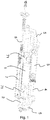
- the cylinder shown in figure 1 is used in the steering devices of a vessel, in particular for outboard marine motors.
- the outboard motors are fastened to the transom of a vessel so as to be mounted rotatably, around a substantially vertical steering axis, through the fastening device object of the present invention, which will be described below.
- the cylinder 1 is slidably mounted on at least one stem 2 coaxial to the cylinder 1.
- a return arm 3 is fastened to the motor and integral with the cylinder 1, for the transmission of the movement of the cylinder 1 to the motor and to obtain the consequent steering movement.
- the translation of the cylinder 1 along the stem 2 allows the rotation of the motor around a vertical axis thanks to the presence of the return arm 3 which transmits the movement of the cylinder 1 to the motor.
- the stem 2 is connected to a fastening device, object of the present invention, of the cylinder 1 to the motor, in a non-sliding manner and so as to allow the relative rotation of the motor with respect to the transom, according to an axis parallel to the axis of the stem 2, the so-called tilt movement of the motor.
- the cylinder-stem system is inserted at least in part inside a corresponding insertion seat belonging to the outboard motor.
- the outboard motor is not shown in the figures to better show the fastening device of the stem-cylinder system to the motor, consisting of a fastening rod 4 which is inserted at least in part inside a special seat of the outboard motor, which is integral with this fastening rod 4, so that the rotation of the fastening rod 4 around the longitudinal axis thereof allows the tilt movement of the outboard motor.
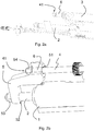
- the fastening rod 4 is illustrated in particular in figures 2a and 2b and has two ends 41.
- FIGS. 2a and 2b only show one end 41, but the fastening device object of the present invention has a symmetrical construction, whereby the ends 41 are provided in the same way.
- the fastening device object of the present invention has two terminal elements 5, such that each terminal element 5 has a first housing seat 51 for inserting the end 41 of the fastening rod 4.
- each terminal element 5 has a second housing seat 52 for inserting a corresponding end of the stem 2.
- Both the first 51 and the second 52 housing seats are provided through through-holes obtained in the thickness of each terminal element 5, such that the ends of the stem 2 and the ends 41 of the fastening rod 4 are inserted completely inside the respective housing seats 52 and 51, protruding by a certain portion.
- the portion of the stem 2 and of the fastening rod 4 protruding with respect to the terminal element 5, can be coupled to clamping nuts, respectively 53 and 54, for locking the stem 2 and the rod 4.
- the stem 2 is locked and has no relative movement with respect to the terminal element, neither translation nor rotation, while the fastening rod 4 is locked so that it cannot move with respect to the terminal element 5, while it can rotate with respect to this terminal element.
- the bushing element 6 has a length such as to completely cover the part of the end 41 inside the housing seat 51.
- the bushing element 6 is made of plastic to electrically insulate the end 41 from the inner walls of the housing seat 51, i.e., to electrically insulate the fastening rod 4 with respect to the terminal element 5.
- the bushing element 6 consists of an inert plastic polymer, so as to facilitate the rotation of the fastening rod 4 with respect to the terminal element 5, preventing the surfaces of the end 41 or the inner walls of the housing seat 51 from wearing.
- the bushing element 6 is illustrated fitted on the end 41, so as to overlap with the outer surface of the fastening rod 4, however preferably, the bushing element 6 is fitted on the inner walls of the housing seat 51 of the terminal element 5.
- the bushing element 6 is integral with the terminal element 5, so it does not rotate in combination with the fastening rod 6, but it is the end 41 which rotates inside the bushing element 6, which remains fastened.
- the fastening element described and shown in figures 2a and 2b can be provided in combination with any actuator cylinder for outboard marine motors, whether a hydraulic, mechanical, electro-hydraulic or electro-mechanical cylinder, without including constructive modifications to the fastening rod 4 or the terminal element 5.
- the cylinder 1 is electrically activated, through control signals generated by an electronic unit comprising an outer casing 7 inside which there is an electronic board 70 ( figures 3 and 4 ) adapted to generate or transmit control signals for the movement of the cylinder 1 depending on the information received through the electric transmission cable 8.
- the transmission cable 8 may be connected to a motion detection unit of a vessel control member, such as a steering wheel, which transforms the rotation of the steering wheel into electrical or data signals, transmitted through the cable 8 to the electronic board 70.
- a vessel control member such as a steering wheel
- the electronic board 70 processes these signals and drives the actuators 71 to move the cylinder 1.
- the processing can take place upstream of the electronic board 70, which can deal with the simple transmission of the activation command of the actuators 71, based on the data already processed and received through the cable 8.
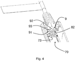
- Figures 3 and 4 show a particular configuration of the connection area between the cable 8 and the electronic board 70.
- all the contents of the outer casing 7 are embedded inside insulating material, such as resins or the like, not shown in the figures for simplicity of display.
- the terminal of the cable 8 is welded to the electronic board 70, through the contacts 73: the cable 8 is in fact covered by an insulating sheath 82, which is removed in the terminal part, to allow the wires of conductive material 81 of the cable 8 to be welded to the contacts 73 of the electronic board 70.
- a protective element 83 is provided, made of a rubber sleeve which covers the cable 8, in particular the insulating sheath 82.
- This rubber sleeve is fastened to the outer casing 7 through a shape coupling: in fact, the protection element 83 has an H-shaped terminal which couples to the initial part 74 of the outer casing 7, which has surfaces with a profile complementary to the H-shaped terminal, as clearly shown in figure 3 .
- the transmission cable 8 is firmly locked with respect to the outer casing 7, thanks to the presence of a locking element 9 of the terminal of the cable 8.
- the locking element 9 has an "omega"-shaped profile, with a central curved part 92 and two flat lateral fins 91.
- the two lateral fins 91 may be attached either to the electronic board 70, or to the inner walls of the outer casing 7, depending on constructive needs.
- the central curved portion 92 overlaps the outer sheath 82, so as to identify a locking seat for the terminal of the cable 8.
- the locking element 9 is configured such that the locking seat has a smaller section than the terminal section of the cable 8.
- the central curved portion 92 may have one or more raised teeth, extending in the direction of the insulating sheath 82.
- teeth will have a shape such as to crush the insulating sheath 82, without damaging or penetrating it, so as to keep the insulation of the cable 8 unchanged.
- the locking element is made of metal material, preferably aluminium, which has a thickness of about 1 mm, so that it can deform if subjected to high pressures, without damaging the electronic board 70 or the interface between the lateral fins 91 and the tightening screws 93.
Landscapes
- Chemical & Material Sciences (AREA)
- Engineering & Computer Science (AREA)
- Combustion & Propulsion (AREA)
- Mechanical Engineering (AREA)
- Ocean & Marine Engineering (AREA)
- Motor Or Generator Frames (AREA)
- Clamps And Clips (AREA)
- Actuator (AREA)
Abstract
Description
- The present invention relates to a device for fastening steering cylinders to outboard marine motors of a vessel.
- The device comprises a fastening rod insertable inside an outboard motor, which rod having each of the ends thereof inserted inside a corresponding housing seat, obtained in a terminal element, such that the fastening rod has a relative rotation with respect to the terminal elements.
- As in the systems known in the art, the terminal elements are in turn fastened to the cylinder.
- Furthermore, the outboard motor is integral with the fastening rod, such that it can oscillate around the longitudinal axis of said fastening rod.
- What is described above is the common configuration for fastening steering cylinders to the outboard motors of a vessel, in which the cylinder is used as a steering member of the outboard motor, which motor is fastened to the vessel.
- According to this configuration, the cylinder rod, i.e., the fastening rod, is fastened with the ends thereof inside two "bull-horns", the terminal elements.
- The rod of the cylinder must be able to rotate around the longitudinal axis thereof, so as to allow the rotation, i.e., the tilt, of the outboard motor with respect to the bull-horn and with respect to the rest of the vessel.
- The interface between the ends of the cylinder rod and the terminal elements is a particularly critical area, since the rod and the terminal elements, i.e., the bull-horns, are generally made of metal, thus a galvanic bridge is created which causes the rotation of the rod to be blocked due to the formation of oxide on the rod, particularly at the ends thereof and/or on the bull-horns.
- The galvanic effect is further amplified if the rod is made of steel and the bull-horns of aluminium.
- In fact, it must be considered that the rod is the point of contact between the motor and the cylinder, so that the vessel, connected to the outboard motor, acting as a negative pole, amplifies the galvanic bridge effect.
- This effect is further amplified in particularly humid and highly saline environments, which are particularly frequent in the case of vessels.
- The accumulation of oxide at the ends of the rod compromises the relative movement of the latter with respect to the terminal elements, preventing the tilt of the outboard motor.
- However, the tilt control of the outboard motor is powerful enough to disrupt the connections between the cylinder and the outboard motor, bending the connecting arms and wearing out the various components, with the locking of the cylinder rod.
- Therefore, the accumulation of oxide caused by the galvanic bridge compromises the correct operation of the motor tilt mechanism, but the operation of the systems known in the state of the art has a further defect related to wear.
- In fact, the relative movement between the rod and the bull-horns can cause the wear or tear of the ends of the cylinder rod or of the terminal elements, depending on the materials with which they are made. Currently the ends of the fastening rod are covered with grease, however with the use of the vessel, the layer of grease is removed and the lubricating effect disappears.
- For this reason, currently some known systems in the state of the art provide for the use of a device adapted to continuously deposit grease on the fastening rod.
- These systems are particularly ineffective, as the deposit of grease does not always occur optimally and within the required times and also adds a component which can fail and make the steering/propulsion part of the vessel even more complex from a constructive point of view.
- There is therefore a need not satisfied by the devices known in the state of the art to provide an outboard marine motor fastening device, which allows to solve the disadvantages described above, avoiding the blockage of the outboard motor tilt control.
- The present invention achieves the above purposes by providing a fastening device as described above, in which at least one insulating element is provided interposed between each end of the fastening rod and the corresponding housing seat.
- Furthermore, the insulating element is configured to at least partially surround the surface of each end.
- Preferably, given the currently known configurations, in which the end of the rod is the male element, inserted inside the corresponding housing seat, the insulating element surrounds, at least equally, the outer surface of each rod end.
- For example, the insulating element can be made of plastic.
- The device object of the present invention therefore includes inserting an insulating element so as to galvanically insulate the rod with respect to the terminal elements and so as to decrease the wear of the latter.
- Furthermore, the provision of the insulating element in plastic, especially in particularly inert polymers, allows, in addition to galvanically insulating the rod, to further limit wear during the rotation of the rod inside the housing seats of the terminal elements.
- According to a possible embodiment, two insulating elements are included for each end, the two insulating elements being spaced apart along the longitudinal axis of the fastening rod and lubricating material being interposed between the two insulating elements.
- This configuration allows the lubricating material to be retained between the two insulating elements, so that it is not dispersed during the rotation of the rod as in the systems known in the state of the art.
- According to a possible embodiment, the insulating element is formed by a bushing element.
- According to a preferred embodiment, the insulating element is fastened to the inner walls of the housing seat, so as to be integral with the terminal element and allow the rotation of the fastening rod.
- Such configuration allows to further decrease wear.
- In fact, in the systems known in the state of the art, it is the bull-horn, i.e., the terminal element, which is the component which tends to wear out most, due to the fact that it is made of aluminium, which deteriorates more than steel during the rotation of the rod.
- Therefore, the insulating element fitted in the housing seat of the terminal element allows to preserve the walls of the housing seat, greatly limiting the wear of the latter.
- According to a possible embodiment of the device object of the present invention, the housing seat consists of a through-hole obtained in the thickness of the terminal element, while the insulating element has a length equal to the length of the through-hole.
- It is evident that the insulating element may have a length such as to entirely overlap the part of the fastening rod which may be in contact with the inner walls of the housing seats of the terminal elements.
- The presence of the insulating element also allows to provide a sort of guide, which avoids unexpected oscillations of the fastening rod during the rotation thereof.
- In particular, the insulating element prevents oscillations of the rod if the ends of the latter wear: in fact, wear increases the clearance between the rod and the terminal elements, thus by decreasing wear, these clearances decrease.
- In view of the advantageous aspects described with regard to the fastening device, the present invention also relates to a double-acting actuator cylinder for outboard marine motors.
- In particular, the outboard marine motors connected to said actuator cylinder have a fastening device to the transom of a vessel provided according to one or more of the features described above.
- Furthermore, the present invention relates to a dual-acting actuator cylinder for outboard marine motors comprising an electronic unit for generating/transmitting electrical control signals of the cylinder.
- The actuator cylinder object of the present invention is generally used in steer by wire type guidance systems, i.e., those systems with an electronic control unit which detects the movement of a control member, such as the rotation of the steering wheel, to generate a command signal to be sent to said cylinder, which deals with the positioning of the outboard motors of a vessel, so as to set the navigation route thereof.
- Therefore, the electronic unit is responsible for processing the detected data and generating command signals, processing which occurs through one or more electronic processing boards.
- In the systems known to the state of the art, the electronic processing board is generally inserted inside an outer casing and has a terminal of an electric transmission cable, covered by an insulating sheath, welded to the board itself.
- Furthermore, the outer casing is generally filled with an insulating material of the resin type or the like.
- As will be evident from the illustration of an embodiment described below, the connection of the terminal of the electrical cable to the electronic board is a critical area for the maintenance of the systems known in the art.
- In fact, since the cable exits the outer casing, it is likely that a possible user will get caught or stumble in the loops made by the cable, tearing the latter at the weakest point, i.e., in the area of connection to the electronic board.
- Furthermore, the connection between the cable terminal and the electronic board is a critical area not only for the risk of tears or breakage which would require the replacement of components, but also for the problem of moisture.
- In fact, the moisture climbs up the cable, runs through the outer sheath and penetrates the outer casing, depositing on the terminals of the cable welded to the electronic board, deteriorating this welding and the consequent contact.
- The outer sheath is in fact made of soft rubbery material, while the resin tends to harden over time: the rubber need only recede, for example due to external agents such as sun, water or salt, to generate a gap in which the moisture penetrates, deteriorating the welded contacts of the cable terminal.
- To solve these disadvantages, the cylinder object of the present invention has a welded cable terminal locking element, which has an "omega"-shaped profile, with a central curved part and two flat lateral fins.
- This locking element is therefore fastened to the outer casing through the lateral fins, so as to overlap with the central curved part of the sheath of the electrical cable terminal and provide a locking seat of the terminal itself.
- According to a possible embodiment, the locking seat provided by the locking element has a smaller section with respect to the section of the cable terminal.
- The omega-shaped element thereby crushes the cable towards the electronic board, eliminating the possible gap which was formed between the rubber and the outer sheath of the cable.
- Furthermore, the locking action also limits the possibility that the rubber of the outer sheath will recede over time.
- In order to increase the pressure and locking action of the locking element towards the cable terminal, according to a refinement the locking seat has at least one raised tooth, which extends in the direction of the terminal.
- Advantageously, the locking element has a thickness of less than one millimetre.
- Furthermore, the locking element is preferably made of aluminium.
- Thanks to this configuration, the locking element can be fastened to the electronic board or the outer casing, so as to crush the cable terminal as described above, but beyond a certain pressure level it can deform, to best adapt to the shape of the cable and recreate the profile of the latter, to avoid the formation of gaps in which moisture can insinuate.
- Lastly, according to a further embodiment, the actuator cylinder described can have a device for fastening to the transom of a vessel, which device is provided according to one or more of the features described above.
- These and other features and advantages of the present invention will become clearer from the following description of some exemplary embodiments illustrated in the attached drawings in which:
-
figure 1 shows a perspective view of an actuator cylinder known in the art; -
figures 2a and 2b show a further embodiment of the fastening device object of the present invention; -
figures 3 and4 show two views of a further embodiment of the actuator cylinder object of the present invention. - It should be noted that the embodiments shown in the figures attached to the present application are shown to better understand the advantages and features of the device and the cylinder claimed below.
- These embodiments are therefore to be intended for purely illustrative and non-limiting purposes of the inventive concept of the present invention, i.e., that of providing a fastening device of an outboard marine motor at the stern of a vessel, which avoids the blocking of the tilt movement of the motor.
- Furthermore, it is specified that in the attached figures the insulating element consists of a bushing element, but it is evident how one or more insulating elements per end, provided for example by gaskets or similar elements, can be provided without substantially modifying the content of the present invention.
- With particular reference to
figure 1 , a dual-acting actuator cylinder according to the state of the art is shown. - The cylinder shown in
figure 1 is used in the steering devices of a vessel, in particular for outboard marine motors. - The outboard motors are fastened to the transom of a vessel so as to be mounted rotatably, around a substantially vertical steering axis, through the fastening device object of the present invention, which will be described below.
- To achieve the steering effect, the
cylinder 1 is slidably mounted on at least onestem 2 coaxial to thecylinder 1. - Furthermore, a
return arm 3 is fastened to the motor and integral with thecylinder 1, for the transmission of the movement of thecylinder 1 to the motor and to obtain the consequent steering movement. - In fact, the translation of the
cylinder 1 along thestem 2 allows the rotation of the motor around a vertical axis thanks to the presence of thereturn arm 3 which transmits the movement of thecylinder 1 to the motor. - Furthermore, the
stem 2 is connected to a fastening device, object of the present invention, of thecylinder 1 to the motor, in a non-sliding manner and so as to allow the relative rotation of the motor with respect to the transom, according to an axis parallel to the axis of thestem 2, the so-called tilt movement of the motor. - In particular, the cylinder-stem system is inserted at least in part inside a corresponding insertion seat belonging to the outboard motor.
- The outboard motor is not shown in the figures to better show the fastening device of the stem-cylinder system to the motor, consisting of a
fastening rod 4 which is inserted at least in part inside a special seat of the outboard motor, which is integral with thisfastening rod 4, so that the rotation of thefastening rod 4 around the longitudinal axis thereof allows the tilt movement of the outboard motor. - The
fastening rod 4 is illustrated in particular infigures 2a and 2b and has two ends 41. - It should be noted that
figures 2a and 2b only show oneend 41, but the fastening device object of the present invention has a symmetrical construction, whereby the ends 41 are provided in the same way. - In particular, the fastening device object of the present invention has two
terminal elements 5, such that eachterminal element 5 has afirst housing seat 51 for inserting theend 41 of thefastening rod 4. - Furthermore, each
terminal element 5 has asecond housing seat 52 for inserting a corresponding end of thestem 2. - Both the first 51 and the second 52 housing seats are provided through through-holes obtained in the thickness of each
terminal element 5, such that the ends of thestem 2 and theends 41 of thefastening rod 4 are inserted completely inside therespective housing seats - Thereby, the portion of the
stem 2 and of thefastening rod 4 protruding with respect to theterminal element 5, can be coupled to clamping nuts, respectively 53 and 54, for locking thestem 2 and therod 4. - It should be noted that the
stem 2 is locked and has no relative movement with respect to the terminal element, neither translation nor rotation, while thefastening rod 4 is locked so that it cannot move with respect to theterminal element 5, while it can rotate with respect to this terminal element. - In particular, there is a
bushing element 6 interposed between theend 41 and the inner walls of thehousing seat 51 of theterminal element 5. - According to the variant shown in
figures 2a and 2b , thebushing element 6 has a length such as to completely cover the part of theend 41 inside thehousing seat 51. - Furthermore, the
bushing element 6 is made of plastic to electrically insulate theend 41 from the inner walls of thehousing seat 51, i.e., to electrically insulate thefastening rod 4 with respect to theterminal element 5. - Advantageously, the
bushing element 6 consists of an inert plastic polymer, so as to facilitate the rotation of thefastening rod 4 with respect to theterminal element 5, preventing the surfaces of theend 41 or the inner walls of thehousing seat 51 from wearing. - In
figure 2a , thebushing element 6 is illustrated fitted on theend 41, so as to overlap with the outer surface of thefastening rod 4, however preferably, thebushing element 6 is fitted on the inner walls of thehousing seat 51 of theterminal element 5. - According to this configuration, the
bushing element 6 is integral with theterminal element 5, so it does not rotate in combination with thefastening rod 6, but it is theend 41 which rotates inside thebushing element 6, which remains fastened. - The fastening element described and shown in
figures 2a and 2b can be provided in combination with any actuator cylinder for outboard marine motors, whether a hydraulic, mechanical, electro-hydraulic or electro-mechanical cylinder, without including constructive modifications to thefastening rod 4 or theterminal element 5. - With particular reference to
figure 1 , thecylinder 1 is electrically activated, through control signals generated by an electronic unit comprising anouter casing 7 inside which there is an electronic board 70 (figures 3 and4 ) adapted to generate or transmit control signals for the movement of thecylinder 1 depending on the information received through theelectric transmission cable 8. - For example, the
transmission cable 8 may be connected to a motion detection unit of a vessel control member, such as a steering wheel, which transforms the rotation of the steering wheel into electrical or data signals, transmitted through thecable 8 to theelectronic board 70. - The
electronic board 70 processes these signals and drives theactuators 71 to move thecylinder 1. - Alternatively, the processing can take place upstream of the
electronic board 70, which can deal with the simple transmission of the activation command of theactuators 71, based on the data already processed and received through thecable 8. -
Figures 3 and4 show a particular configuration of the connection area between thecable 8 and theelectronic board 70. - It should be noted that according to a preferred embodiment variant, all the contents of the
outer casing 7 are embedded inside insulating material, such as resins or the like, not shown in the figures for simplicity of display. - With particular reference to
figures 3 and4 , the terminal of thecable 8 is welded to theelectronic board 70, through the contacts 73: thecable 8 is in fact covered by an insulatingsheath 82, which is removed in the terminal part, to allow the wires ofconductive material 81 of thecable 8 to be welded to thecontacts 73 of theelectronic board 70. - As shown in
figures 3 and4 , near the terminal of thecable 8, in particular at the interface area between thecable 8 and theouter casing 7, aprotective element 83 is provided, made of a rubber sleeve which covers thecable 8, in particular the insulatingsheath 82. - This rubber sleeve is fastened to the
outer casing 7 through a shape coupling: in fact, theprotection element 83 has an H-shaped terminal which couples to theinitial part 74 of theouter casing 7, which has surfaces with a profile complementary to the H-shaped terminal, as clearly shown infigure 3 . - Furthermore, the
transmission cable 8 is firmly locked with respect to theouter casing 7, thanks to the presence of alocking element 9 of the terminal of thecable 8. - The locking
element 9 has an "omega"-shaped profile, with a centralcurved part 92 and two flatlateral fins 91. - As clearly shown in
figure 4 , the twolateral fins 91 may be attached either to theelectronic board 70, or to the inner walls of theouter casing 7, depending on constructive needs. - Preferably tightening
screws 93 are used, screwed into the thickness of the walls of theouter casing 7 or of theelectronic board 70. - The central
curved portion 92 overlaps theouter sheath 82, so as to identify a locking seat for the terminal of thecable 8. - In particular, the locking
element 9 is configured such that the locking seat has a smaller section than the terminal section of thecable 8. - It follows that the locking
element 9 crushes the terminal of thecable 8 towards theelectronic board 70. - Depending on the dimensions of the
locking element 9, not only theouter sheath 82, but also the wires ofconductive material 81 of thecable 8 may deform. - In order to increase the locking of the terminal of the
cable 8, the centralcurved portion 92 may have one or more raised teeth, extending in the direction of the insulatingsheath 82. - These teeth will have a shape such as to crush the insulating
sheath 82, without damaging or penetrating it, so as to keep the insulation of thecable 8 unchanged. - Lastly, it should be noted that the locking element is made of metal material, preferably aluminium, which has a thickness of about 1 mm, so that it can deform if subjected to high pressures, without damaging the
electronic board 70 or the interface between thelateral fins 91 and the tightening screws 93. - While the invention is susceptible to various modifications and alternative constructions, some preferred embodiments have been shown in the drawings and described in detail.
- It should be understood, however, that there is no intention of limiting the invention to the specific illustrated embodiment but, on the contrary, it aims to cover all the modifications, alternative constructions, and equivalents falling within the scope of the invention as defined in the claims.
- The use of "for example", "etc.", "or" refers to non-exclusive non-limiting alternatives, unless otherwise stated.
- The use of "includes" means "includes but not limited to", unless otherwise stated.
Claims (10)
- Device for fastening steering actuator cylinders to outboard marine motors, comprising a fastening rod (4) insertable inside an outboard motor, which fastening rod (4) has each of the ends (41) thereof inserted inside a corresponding housing seat (51) obtained in a terminal element (5), such that said fastening rod (4) has a relative rotation with respect to said terminal elements (5), which terminal elements are fastened to said steering cylinder,
and said outboard motor being integral with said fastening rod (4), so that said outboard motor can oscillate around the longitudinal axis of said fastening rod (4),
characterized in that
at least one insulating element is provided interposed between each end (41) of said fastening rod (4) and the corresponding housing seat (51),
said insulating element being configured to at least partially surround the surface of each end. - Device according to claim 1, wherein two insulating elements are provided for each end, the two insulating elements being spaced apart along the longitudinal axis of said fastening rod (4) and lubricating material being interposed between the two said insulating elements.
- Device according to claim 1, wherein said insulating element is formed by a bushing element (6).
- Device according to claim 1, wherein said insulating element is fastened to the inner walls of said housing seat (51), so as to be integral with said terminal element (5) and allow the rotation of said fastening rod (4).
- Device according to one or more of the preceding claims, wherein said housing seat (51) consists of a through-hole obtained in the thickness of said terminal element (5), said insulating element having a length equal to the length of said through-hole.
- Dual-acting actuator cylinder for outboard marine motors, comprising a fastening device to said outboard motors,
characterized in that
said fastening device is provided according to one or more of claims 1 to 5. - Dual-acting actuator cylinder for outboard marine motors comprising an electronic unit for generating/transmitting electrical control signals of said cylinder,
which electronic unit comprises at least one processing electronic board (70) inserted inside an outer casing (7), to which electronic board (70) is welded a terminal of an electric transmission cable (8), covered with an insulating sheath (82),
characterized in that
a locking element (9) of said welded cable terminal (8) is provided, which locking element (9) has an "omega"-shaped profile, with a central curved part (92) and two flat lateral fins (91), such that said locking element (9) is fastened to said outer casing (7) through said lateral fins (91) and so as to overlap with the central curved part (92) with the sheath (82) of said terminal and obtain a locking seat of said terminal. - Cylinder according to claim 7, wherein said locking seat has a smaller section with respect to the section of said cable terminal.
- Cylinder according to claim 7, wherein said locking seat has at least one raised tooth, which extends in the direction of said terminal.
- Cylinder according to claim 7, wherein a fastening device is provided for fastening said cylinder to the transom of a vessel, which device is provided according to one or more of claims 1 to 5.
Applications Claiming Priority (1)
| Application Number | Priority Date | Filing Date | Title |
|---|---|---|---|
| IT102019000022374A IT201900022374A1 (en) | 2019-11-28 | 2019-11-28 | Steering cylinder attachment device for marine outboard engines and double acting cylinder for outboard marine engines |
Publications (3)
| Publication Number | Publication Date |
|---|---|
| EP3828074A2 true EP3828074A2 (en) | 2021-06-02 |
| EP3828074A3 EP3828074A3 (en) | 2021-08-18 |
| EP3828074B1 EP3828074B1 (en) | 2026-01-28 |
Family
ID=69904079
Family Applications (1)
| Application Number | Title | Priority Date | Filing Date |
|---|---|---|---|
| EP20210254.7A Active EP3828074B1 (en) | 2019-11-28 | 2020-11-27 | Device for fastening steering actuator cylinders to outboard marine motors |
Country Status (3)
| Country | Link |
|---|---|
| US (1) | US11492089B2 (en) |
| EP (1) | EP3828074B1 (en) |
| IT (1) | IT201900022374A1 (en) |
Family Cites Families (5)
| Publication number | Priority date | Publication date | Assignee | Title |
|---|---|---|---|---|
| US4109978A (en) * | 1976-10-14 | 1978-08-29 | Electric Machinery Mfg. Co. | Electrically insulated sleeve bearing and method of making same |
| US4932795A (en) * | 1988-11-10 | 1990-06-12 | Outboard Marine Corporation | Electrically conductive plastic bushings for marine propulsion devices |
| JP4298017B2 (en) * | 1998-09-25 | 2009-07-15 | ヤマハ発動機株式会社 | Outboard motor |
| US8944690B2 (en) * | 2009-08-28 | 2015-02-03 | Saint-Gobain Performance Plastics Pampus Gmbh | Corrosion resistant bushing |
| US9045212B2 (en) * | 2012-03-22 | 2015-06-02 | Yamaha Hatsudoki Kabushiki Kaisha | Suspension device for outboard motor and vessel propulsion apparatus |
-
2019
- 2019-11-28 IT IT102019000022374A patent/IT201900022374A1/en unknown
-
2020
- 2020-11-26 US US17/105,570 patent/US11492089B2/en active Active
- 2020-11-27 EP EP20210254.7A patent/EP3828074B1/en active Active
Also Published As
| Publication number | Publication date |
|---|---|
| IT201900022374A1 (en) | 2021-05-28 |
| US11492089B2 (en) | 2022-11-08 |
| US20210163110A1 (en) | 2021-06-03 |
| EP3828074B1 (en) | 2026-01-28 |
| EP3828074A3 (en) | 2021-08-18 |
Similar Documents
| Publication | Publication Date | Title |
|---|---|---|
| EP2319131B1 (en) | Connector | |
| EP0265276B1 (en) | Coaxial connector moisture seal | |
| US8876542B2 (en) | Connector and construction machine | |
| EP1958871B1 (en) | Detection of load bearing by a secondary channel of a flight control actuator | |
| EP2403072A1 (en) | Connector device for construction machine | |
| EP3828074B1 (en) | Device for fastening steering actuator cylinders to outboard marine motors | |
| US9887507B2 (en) | Sensor system with a rotatable electrical outlet | |
| WO2007094406A1 (en) | Wire with terminal | |
| JP5729608B2 (en) | Connectors and joint connectors | |
| JPH0333786B2 (en) | ||
| US10005533B2 (en) | Marine electric power assist steering system with cable | |
| US20210265899A1 (en) | Electrical drive device and electrical power steering device | |
| US20160116330A1 (en) | Ultrasonic sensor | |
| KR102713184B1 (en) | Motor control apparatus | |
| JP7788534B2 (en) | Systems and methods for sealing metallic fasteners from electrolytes in areas of dissimilar metals | |
| US20110252894A1 (en) | Fence jumping detection rod having elastically supported ball | |
| EP1980777A2 (en) | Hydraulic control valve with stroke transducer | |
| KR100629198B1 (en) | Fixing structure of sensor harness | |
| CN210156653U (en) | Pressure welding type digital signal cable connector for ships | |
| JP5859750B2 (en) | Wiring device | |
| JP2718514B2 (en) | Underwater electrode structure for energization | |
| US12006012B2 (en) | Steering apparatuses and actuator apparatuses | |
| WO2001093396A1 (en) | Electrical cable gland | |
| CN103201534A (en) | Mooring device and steering mooring mechanism using same | |
| JP2960637B2 (en) | Corrosion protection structure of steel pipe pile |
Legal Events
| Date | Code | Title | Description |
|---|---|---|---|
| PUAI | Public reference made under article 153(3) epc to a published international application that has entered the european phase |
Free format text: ORIGINAL CODE: 0009012 |
|
| STAA | Information on the status of an ep patent application or granted ep patent |
Free format text: STATUS: THE APPLICATION HAS BEEN PUBLISHED |
|
| AK | Designated contracting states |
Kind code of ref document: A2 Designated state(s): AL AT BE BG CH CY CZ DE DK EE ES FI FR GB GR HR HU IE IS IT LI LT LU LV MC MK MT NL NO PL PT RO RS SE SI SK SM TR |
|
| PUAL | Search report despatched |
Free format text: ORIGINAL CODE: 0009013 |
|
| AK | Designated contracting states |
Kind code of ref document: A3 Designated state(s): AL AT BE BG CH CY CZ DE DK EE ES FI FR GB GR HR HU IE IS IT LI LT LU LV MC MK MT NL NO PL PT RO RS SE SI SK SM TR |
|
| RIC1 | Information provided on ipc code assigned before grant |
Ipc: B63H 20/08 20060101AFI20210714BHEP Ipc: B63H 20/10 20060101ALI20210714BHEP Ipc: B63H 20/12 20060101ALI20210714BHEP |
|
| STAA | Information on the status of an ep patent application or granted ep patent |
Free format text: STATUS: REQUEST FOR EXAMINATION WAS MADE |
|
| 17P | Request for examination filed |
Effective date: 20220217 |
|
| RBV | Designated contracting states (corrected) |
Designated state(s): AL AT BE BG CH CY CZ DE DK EE ES FI FR GB GR HR HU IE IS IT LI LT LU LV MC MK MT NL NO PL PT RO RS SE SI SK SM TR |
|
| STAA | Information on the status of an ep patent application or granted ep patent |
Free format text: STATUS: EXAMINATION IS IN PROGRESS |
|
| 17Q | First examination report despatched |
Effective date: 20231115 |
|
| GRAP | Despatch of communication of intention to grant a patent |
Free format text: ORIGINAL CODE: EPIDOSNIGR1 |
|
| STAA | Information on the status of an ep patent application or granted ep patent |
Free format text: STATUS: GRANT OF PATENT IS INTENDED |
|
| INTG | Intention to grant announced |
Effective date: 20250926 |
|
| GRAS | Grant fee paid |
Free format text: ORIGINAL CODE: EPIDOSNIGR3 |
|
| GRAA | (expected) grant |
Free format text: ORIGINAL CODE: 0009210 |
|
| STAA | Information on the status of an ep patent application or granted ep patent |
Free format text: STATUS: THE PATENT HAS BEEN GRANTED |
|
| AK | Designated contracting states |
Kind code of ref document: B1 Designated state(s): AL AT BE BG CH CY CZ DE DK EE ES FI FR GB GR HR HU IE IS IT LI LT LU LV MC MK MT NL NO PL PT RO RS SE SI SK SM TR |
|
| REG | Reference to a national code |
Ref country code: CH Ref legal event code: F10 Free format text: ST27 STATUS EVENT CODE: U-0-0-F10-F00 (AS PROVIDED BY THE NATIONAL OFFICE) Effective date: 20260128 Ref country code: GB Ref legal event code: FG4D |
|
| REG | Reference to a national code |
Ref country code: DE Ref legal event code: R096 Ref document number: 602020065815 Country of ref document: DE |
|
| REG | Reference to a national code |
Ref country code: IE Ref legal event code: FG4D |