EP3827973A1 - Procede de fabrication d'une piece en materiau composite comportant une premiere puis une deuxieme polymerisation - Google Patents
Procede de fabrication d'une piece en materiau composite comportant une premiere puis une deuxieme polymerisation Download PDFInfo
- Publication number
- EP3827973A1 EP3827973A1 EP20198739.3A EP20198739A EP3827973A1 EP 3827973 A1 EP3827973 A1 EP 3827973A1 EP 20198739 A EP20198739 A EP 20198739A EP 3827973 A1 EP3827973 A1 EP 3827973A1
- Authority
- EP
- European Patent Office
- Prior art keywords
- polymerization
- infusion
- temperature
- composite material
- dry fibers
- Prior art date
- Legal status (The legal status is an assumption and is not a legal conclusion. Google has not performed a legal analysis and makes no representation as to the accuracy of the status listed.)
- Granted
Links
Images

Classifications
-
- B—PERFORMING OPERATIONS; TRANSPORTING
- B29—WORKING OF PLASTICS; WORKING OF SUBSTANCES IN A PLASTIC STATE IN GENERAL
- B29C—SHAPING OR JOINING OF PLASTICS; SHAPING OF MATERIAL IN A PLASTIC STATE, NOT OTHERWISE PROVIDED FOR; AFTER-TREATMENT OF THE SHAPED PRODUCTS, e.g. REPAIRING
- B29C70/00—Shaping composites, i.e. plastics material comprising reinforcements, fillers or preformed parts, e.g. inserts
- B29C70/04—Shaping composites, i.e. plastics material comprising reinforcements, fillers or preformed parts, e.g. inserts comprising reinforcements only, e.g. self-reinforcing plastics
- B29C70/28—Shaping operations therefor
- B29C70/40—Shaping or impregnating by compression not applied
- B29C70/42—Shaping or impregnating by compression not applied for producing articles of definite length, i.e. discrete articles
- B29C70/44—Shaping or impregnating by compression not applied for producing articles of definite length, i.e. discrete articles using isostatic pressure, e.g. pressure difference-moulding, vacuum bag-moulding, autoclave-moulding or expanding rubber-moulding
- B29C70/443—Shaping or impregnating by compression not applied for producing articles of definite length, i.e. discrete articles using isostatic pressure, e.g. pressure difference-moulding, vacuum bag-moulding, autoclave-moulding or expanding rubber-moulding and impregnating by vacuum or injection
-
- B—PERFORMING OPERATIONS; TRANSPORTING
- B29—WORKING OF PLASTICS; WORKING OF SUBSTANCES IN A PLASTIC STATE IN GENERAL
- B29C—SHAPING OR JOINING OF PLASTICS; SHAPING OF MATERIAL IN A PLASTIC STATE, NOT OTHERWISE PROVIDED FOR; AFTER-TREATMENT OF THE SHAPED PRODUCTS, e.g. REPAIRING
- B29C70/00—Shaping composites, i.e. plastics material comprising reinforcements, fillers or preformed parts, e.g. inserts
- B29C70/04—Shaping composites, i.e. plastics material comprising reinforcements, fillers or preformed parts, e.g. inserts comprising reinforcements only, e.g. self-reinforcing plastics
- B29C70/06—Fibrous reinforcements only
- B29C70/10—Fibrous reinforcements only characterised by the structure of fibrous reinforcements, e.g. hollow fibres
- B29C70/16—Fibrous reinforcements only characterised by the structure of fibrous reinforcements, e.g. hollow fibres using fibres of substantial or continuous length
-
- B—PERFORMING OPERATIONS; TRANSPORTING
- B29—WORKING OF PLASTICS; WORKING OF SUBSTANCES IN A PLASTIC STATE IN GENERAL
- B29C—SHAPING OR JOINING OF PLASTICS; SHAPING OF MATERIAL IN A PLASTIC STATE, NOT OTHERWISE PROVIDED FOR; AFTER-TREATMENT OF THE SHAPED PRODUCTS, e.g. REPAIRING
- B29C70/00—Shaping composites, i.e. plastics material comprising reinforcements, fillers or preformed parts, e.g. inserts
- B29C70/04—Shaping composites, i.e. plastics material comprising reinforcements, fillers or preformed parts, e.g. inserts comprising reinforcements only, e.g. self-reinforcing plastics
- B29C70/28—Shaping operations therefor
- B29C70/54—Component parts, details or accessories; Auxiliary operations, e.g. feeding or storage of prepregs or SMC after impregnation or during ageing
- B29C70/545—Perforating, cutting or machining during or after moulding
-
- B—PERFORMING OPERATIONS; TRANSPORTING
- B29—WORKING OF PLASTICS; WORKING OF SUBSTANCES IN A PLASTIC STATE IN GENERAL
- B29K—INDEXING SCHEME ASSOCIATED WITH SUBCLASSES B29B, B29C OR B29D, RELATING TO MOULDING MATERIALS OR TO MATERIALS FOR MOULDS, REINFORCEMENTS, FILLERS OR PREFORMED PARTS, e.g. INSERTS
- B29K2105/00—Condition, form or state of moulded material or of the material to be shaped
- B29K2105/24—Condition, form or state of moulded material or of the material to be shaped crosslinked or vulcanised
- B29K2105/243—Partially cured
-
- B—PERFORMING OPERATIONS; TRANSPORTING
- B29—WORKING OF PLASTICS; WORKING OF SUBSTANCES IN A PLASTIC STATE IN GENERAL
- B29L—INDEXING SCHEME ASSOCIATED WITH SUBCLASS B29C, RELATING TO PARTICULAR ARTICLES
- B29L2031/00—Other particular articles
- B29L2031/30—Vehicles, e.g. ships or aircraft, or body parts thereof
- B29L2031/3076—Aircrafts
- B29L2031/3082—Fuselages
-
- B—PERFORMING OPERATIONS; TRANSPORTING
- B29—WORKING OF PLASTICS; WORKING OF SUBSTANCES IN A PLASTIC STATE IN GENERAL
- B29L—INDEXING SCHEME ASSOCIATED WITH SUBCLASS B29C, RELATING TO PARTICULAR ARTICLES
- B29L2031/00—Other particular articles
- B29L2031/30—Vehicles, e.g. ships or aircraft, or body parts thereof
- B29L2031/3076—Aircrafts
- B29L2031/3085—Wings
Definitions
- the present invention relates to a method of manufacturing a part made of composite material comprising a first then a second polymerization.
- a composite material part consists of a reinforcement comprising fibers impregnated with a resin matrix.
- the fibers may or may not be woven.
- such a composite part can be produced according to a resin infusion process, “Liquid Resin Infusion” in English.
- a resin infusion process “Liquid Resin Infusion” in English.
- dry fibers are evacuated through a vacuum film 4d on a counterform 2, as shown in figure 1 .
- the dry fibers are then impregnated with the resin which migrates thanks to the vacuum.
- Such a method includes a first step, called draping, during which the dry fibers are draped or stacked on the counter-form 2.
- infusion consumables are put in place.
- the term “infusion consumable” is understood to mean all the elements necessary for the infusion of the reinforcement.
- the dry fibers are covered by peripheral fabrics.
- the peripheral fabrics are, by way of example, a tear-off fabric 4a placed on the dry fibers, a semi-porous membrane 4b covering the tear-off fabric 4a, a drainage fabric 4c covering the tear-off fabric 4b.
- a 4d vacuum film also called a “bladder”, configured to create a hermetic enclosure S around the dry fibers.
- the vacuum film 4d is sealed to the counter-form 2 by at least one peripheral seal 3. To allow the supply of resin into the enclosure and the suction of air to create air.
- the vacuum film 4d comprises a first orifice 5a connected to an infusion means and a second orifice 5b connected to a suction means.
- a third step called hot compaction the dry fibers are placed under vacuum at a compaction temperature. This step helps prevent the formation of folds between the fibers. dry fibers and to compact the dry fibers during the resin infusion, in order to increase the volume ratio of fibers in the part.
- a fourth step, called infusion a vacuum is created by the suction of air by the suction means 5b and resin is injected by the infusion means 5a. Under the action of a vacuum, the dry fibers are infused in order to create the reinforcement 1.
- the reinforcement 1 is subjected to a polymerization cycle in order to be consolidated and obtain a piece in composite material.
- the composite material part is demolded and machined during a sixth step.
- the polymerization of a composite material part can generate a phenomenon called edge effect due to the creep of the resin through the dry fibers and induces a thickness of the composite material part at the periphery less than the desired thickness.
- the machining aims to eliminate the peripheral zone in order to obtain a part made of composite material of constant thickness.
- the composite material part is therefore manufactured according to dimensions greater than the desired final dimensions, in anticipation of the machining step.
- the method according to the prior art has several drawbacks.
- the machining of the solid composite part requires the use of specific tools capable of cutting such a part, which makes this step time-consuming and expensive.
- the shape of the composite material part does not correspond to the desired final shape, it is not possible to modify it, because the part is no longer manageable. It is therefore necessary to throw it away.
- the hot compaction step is time consuming, because it is necessary to wait for the compaction temperature to be reached.
- the invention relates to a method of manufacturing a part made of composite material aimed at simplifying the manufacture of a part made of composite material.
- the present invention proposes a method of manufacturing a part made of composite material which does not have the drawbacks of the prior art.
- Such a manufacturing process makes it possible to dispense with the compacting step of the prior art, and to simplify the manufacturing process, the draping and dressing step and the infusion step being carried out on a same tools. If necessary after the first polymerization, the intermediate reinforcement can be reworked and machined thus avoiding being scrapped for non-compliance.
- the forming step is prior to the infusion of the dry fibers.
- the forming step is subsequent to the infusion of the dry fibers.
- the structure of an aircraft comprises a fuselage 10 and a wing 11 connected by a central wing box 12.
- a central wing box 12 can be made from parts of composite material, such as an upper panel 13, a lower panel 14, a front spar 15 and a rear spar 16.
- the upper and lower panels 13, 14 and front spars and rear 15, 16 are assembled in pairs using L-shaped angles 17 so as to form the central wing box 12, as shown in figure 3 .
- the figure 4 presents a method of manufacturing a composite material part of a central wing box 12 of an aircraft, for example an L-shaped angle bracket 17.
- the method comprises a first step of layup 110 flat of dry fibers.
- the dry fibers are draped flat on a first vacuum film 40e placed on a flat surface 21 of a draping tool 20, as shown in figure 5 .
- this step is followed by a dressing step 120 configured to set up infusion consumables.
- this dressing step 120 consists in successively placing peripheral fabrics on the folds of dry fibers, such as a tear-off fabric 40a placed above the dry fibers, a semi-porous membrane 40b covering the tear cloth 40a, and a drainage cloth 40c covering the tear cloth 40b.
- the dry fibers and the peripheral tissues are maintained in a hermetic enclosure S by at least one vacuum film 40d.
- the dimensions of the peripheral fabrics 40a, 40b, 40c and of the at least one vacuum film 40d are greater than the dimensions of the dry fibers so that the periphery of the peripheral fabrics 40a, 40b, 40c covers the entire free face of the fibers.
- the vacuum film 40d has a first port 50a configured to be connected to an infusion means and a second port 50b configured to be connected to a suction means. Then, the first and second vacuum films 40e and 40d are joined at their periphery, in order to create the hermetic enclosure S around the dry fibers.
- the first and second evacuating films 40e and 40d may be heat sealed or be joined by a peripheral seal 50c, thereby forming a sealed bag around the dry fibers.
- the method then comprises a step 130 of infusing the dry fibers.
- the infusion means brings resin into the hermetic enclosure S via the first orifice 50a, and the suction means sucks the air present in the enclosure via the second orifice 50b, driving the resin through the dry fibers to create a reinforcement 30.
- the infusion is carried out at an infusion temperature configured to reduce the viscosity of the resin, for example 110 ° C.
- the method comprises a forming step 131 prior to the infusion step 130.
- a forming step 131 the dry fibers enclosed in the hermetic bag are positioned on a counter-form complementary to the shape of the desired composite part.
- a vacuum can be created in the hermetic bag favoring the shaping of the dry fibers on the surface of the counterform.
- the method comprises a forming step 132 subsequent to the infusion step 130.
- the infusion step 130 is therefore carried out flat, for example on the draping tool 20, which favors the displacement of the resin through the dry fibers and accelerates the infusion compared to an infusion which does not take place flat.
- the reinforcement 30 thus created is moved on a counter-form, not shown in the figures.
- the resin present between the fibers serves as a lubricant and promotes the forming of the reinforcement 30.
- the forming step 132 is carried out at room temperature, preferably at 30 ° C.
- the method comprises a first polymerization 140 of the reinforcement 30 at a first polymerization temperature T1.
- This step 140 is configured to obtain a hardening of the resin of 20 to 30%.
- the reinforcement thus obtained called intermediate reinforcement, can be handled by an operator, that is to say which is not completely solidified and its geometry can be modified.
- the first polymerization 140 less than or equal to 150 ° C. for a period of less than equal to 60 minutes.
- the first polymerization 140 is carried out at a temperature T1 equal to 150 ° C., for 60 minutes.
- the method then comprises a step 150 of demolding and machining the intermediate reinforcement.
- the intermediate reinforcement being partially cured and semi-hard, it maintains the desired final shape while being easy to handle for removing infusion consumables, touch-ups and machining.
- holes or orifices can be machined, the peripheral edges can be cut to adapt the dimensions of the intermediate reinforcement 30 to the dimensions of the desired composite part and at the same time to eliminate the edge effects which appear during cutting. 'a polymerization, etc. Machining on the intermediate reinforcement results in clean machined edges.
- the intermediate reinforcement is machined, the latter is positioned on the counter-form before undergoing a second polymerization 160 configured to solidify the intermediate reinforcement and obtain the final composite material part.
- the value of the second polymerization temperature T2 is therefore higher than the value of the first polymerization temperature.
- the second polymerization 160 is carried out at a second polymerization temperature T2 of less than or equal to 180 ° C. for a period of less than or equal to 120 minutes, preferably 180 ° C. for 120 minutes.
- the intermediate reinforcement is polymerized between a female part and a male part of a mold, consequently promoting a homogeneous distribution of heat and a homogeneous polymerization of the intermediate reinforcement.
- the polymerization temperatures T1 and T2 can be reached by infrared radiation, by means of infrared lamps positioned near the reinforcement 30 or by convection via the forming tool 20.
Landscapes
- Engineering & Computer Science (AREA)
- Chemical & Material Sciences (AREA)
- Composite Materials (AREA)
- Mechanical Engineering (AREA)
- Textile Engineering (AREA)
- Moulding By Coating Moulds (AREA)
- Casting Or Compression Moulding Of Plastics Or The Like (AREA)
Abstract
- Drapage (110) et habillage (120) à plat de fibres sèches sur une surface plane (21) d'un outillage de drapage (20) ;
- Infusion des fibres sèches (130) par la résine ;
- Formage (131, 132) des fibres sèches sur un contre moule ;
- Première polymérisation (140) à une première température de polymérisation (T1), la première polymérisation (140) étant configurée pour obtenir un durcissement de la résine de 20 à 30% afin d'obtenir un renfort intermédiaire, la première polymérisation (140) étant postérieure à l'étape d'infusion (130) et de formage (131, 132) ;
- Démoulage et usinage (150) du renfort intermédiaire ;
- Deuxième polymérisation (160) du renfort intermédiaire usiné à une deuxième température de polymérisation (T2), la valeur de la deuxième température (T2) étant supérieure à la valeur de la première température (T1).
Description
- La présente invention se rapporte à un procédé de fabrication d'une pièce en matériau composite comportant une première puis une deuxième polymérisation.
- Une pièce en matériau composite est constituée d'un renfort comportant des fibres imprégnées d'une matrice en résine. Les fibres peuvent être tissées ou non.
- Selon un mode de réalisation connu, une telle pièce composite peut être réalisée selon un procédé par infusion de résine, « Liquid Resin Infusion » en anglais. Lors d'un tel procédé, des fibres sèches sont mises sous vide par le biais d'un film de mise sous vide 4d sur une contre forme 2, tel que représente en
figure 1 . Les fibres sèches sont ensuite imprégnées par de la résine qui migre grâce au vide. Un tel procédé comporte une première étape, dite de drapage, durant laquelle les fibres sèches sont drapées ou empilées sur la contre forme 2. Lors d'une deuxième étape, dite d'habillage, des consommables d'infusion sont mis en place. On entend par « consommable d'infusion » tous les éléments nécessaires à l'infusion du renfort. Durant cette étape d'habillage, les fibres sèches sont recouvertes par des tissus périphériques. Les tissus périphériques sont, à titre d'exemples, un tissu d'arrachage 4a disposé sur les fibres sèches, une membrane semi poreuse 4b couvrant le tissu d'arrachage 4a, un tissu de drainage 4c couvrant le tissu d'arrachage 4b. Pour permettre une infusion des fibres homogène, l'infusion s'effectue sous vide. Les fibres sèches et les tissus périphériques sont dès lors recouverts d'un film de mise sous vide 4d, aussi appelé « vessie », configuré pour créer une enceinte hermétique S autour des fibres sèches. Selon un mode de réalisation, le film de mise sous vide 4d est scellé à la contre forme 2 par au moins un joint périphérique 3. Pour permettre l'apport de résine dans l'enceinte et l'aspiration de l'air pour créer du vide, le film de mise sous vide 4d comporte un premier orifice 5a relié à un moyen d'infusion et un deuxième orifice 5b relié à un moyen d'aspiration. Lors d'une troisième étape dite de compactage à chaud, les fibres sèches sont mises sous vide à une température de de compactage. Cette étape permet d'empêcher la formation de plis entre les fibres sèches et de compacter les fibres sèches lors de l'infusion de résine, ceci afin d'augmenter le taux volumique de fibres dans la pièce. Lors d'une quatrième étape, dite d'infusion, du vide est créé par l'aspiration de l'air par le moyen d'aspiration 5b et de la résine est injectée par le moyen d'infusion 5a. Sous l'action du vide, les fibres sèches sont infusées afin de créer le renfort 1. Lors d'une cinquième étape, dite de polymérisation, le renfort 1 est soumis à un cycle de polymérisation afin d'être consolidé et obtenir une pièce en matériau composite. Après l'étape de polymérisation, la pièce en matériau composite est démoulée et usinée au cours d'une sixième étape. La polymérisation d'une pièce en matériau composite peut générer un phénomène dit d'effet de bord due au fluage de la résine au travers des fibres sèches et induit une épaisseur de la pièce en matériau composite en périphérie inférieure à l'épaisseur souhaitée. L'usinage vise à supprimer la zone périphérique afin d'obtenir une pièce en matériau composite d'épaisseur constante. La pièce en matériau composite est dès lors fabriquée selon des dimensions supérieures aux dimensions finales souhaitées, en prévision de l'étape d'usinage. - Le procédé selon l'art antérieur présente plusieurs inconvénients. En effet, l'usinage de la pièce composite solide nécessite l'utilisation d'outils spécifiques capables de découper une telle pièce ce qui rend cette étape chronophage et couteuse. Lorsque la forme de la pièce en matériau composite ne correspond pas à la forme finale désirée, il n'est pas possible de la modifier, car la pièce n'est plus maniable. Il est dès lors nécessaire de la jeter. Enfin l'étape de compactage à chaud est chronophage, car il est nécessaire d'attendre que la température de compactage soit atteinte.
- L'invention se rapporte à un procédé de fabrication d'une pièce en matériau composite visant à simplifier la fabrication d'une pièce en matériau composite.
- La présente invention propose un procédé de fabrication d'une pièce en matériau composite qui ne présente pas les inconvénients de l'art antérieur.
- A cet effet, elle concerne un procédé de fabrication d'une pièce en matériau composite comportant un renfort composé de fibres imprégnées d'une matrice en résine. Le procédé est remarquable en ce qu'il comporte les étapes suivantes :
- Drapage et habillage à plat de fibres sèches sur une surface plane d'un outillage de drapage ;
- Infusion des fibres sèches par la résine ;
- Formage des fibres sèches sur un contre moule ;
- Première polymérisation à une première température de polymérisation, la première polymérisation étant configurée pour obtenir un durcissement de la résine de 20 à 30% afin d'obtenir un renfort intermédiaire, la première polymérisation étant postérieure à l'étape d'infusion et de formage ;
- Démoulage et usinage du renfort intermédiaire ;
- Deuxième polymérisation du renfort intermédiaire usiné à une deuxième température de polymérisation, la valeur de la deuxième température étant supérieure à la valeur de la première température.
- Un tel procédé de fabrication permet de s'affranchir de l'étape de compactage de l'art antérieur, et de simplifier le procédé de fabrication, l'étape de drapage et d'habillage et l'étape d'infusion étant réalisées sur un même outillage. Si nécessaire après la première polymérisation, le renfort intermédiaire peut être retouché et usiné évitant ainsi d'être mis au rebut pour non-conformité.
- Selon un mode de réalisation, l'étape de formage est antérieure à l'infusion des fibres sèches.
- Selon un deuxième mode de réalisation l'étape de formage est postérieure à l'infusion des fibres sèches.
- Un tel procédé de fabrication comporte d'autres caractéristiques remarquables prises séparément ou en combinaison :
- l'étape d'infusion des fibres sèches est réalisée à une température d'infusion de 110°C ;
- l'étape de formage est réalisée à une température inférieure à 30°C ;
- la première polymérisation est réalisée à une température inférieure ou égale à 150°C, pendant une durée inférieure ou égale à 60 minutes, de préférence égale à 150°C pendant 60 minutes ;
- la deuxième polymérisation est réalisée à une température inférieure ou égale à 180°C pendant une durée inférieure ou égale à 120 minutes, de préférence égale à 180°C pendant 120 minutes.
- D'autres performances, détails et avantages de l'invention ressortiront plus clairement de la description détaillée donnée ci-après à titre indicatif en relation avec des dessins parmi lesquels :
- la
figure 1 est une vue en coupe d'un renfort et de consommables d'infusion lors d'une étape d'infusion d'un procédé par infusion de résine selon l'art antérieur ; - la
figure 2 est une vue en perspective d'un aéronef et d'un caisson central de voilure ; - la
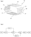
figure 3 est une vue éclatée d'un caisson central de voilure comportant au moins une cornière d'un aéronef en matériau composite fabriquée à partir du procédé de fabrication d'une pièce en matériau composite conforme à un mode de réalisation de l'invention ; - la
figure 4 est une vue présentant les étapes d'un procédé de fabrication d'une pièce en matériau composite conforme à un mode de réalisation de l'invention ; et - la
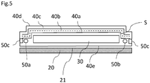
figure 5 est une vue en coupe d'un outillage de drapage d'un renfort et de consommables d'infusion lors d'une étape d'infusion du procédé de fabrication d'une pièce en matériau composite. - Comme illustré sur la
figure 2 , la structure d'un aéronef comporte un fuselage 10 et une voilure 11 reliés par un caisson central de voilure 12. - Un caisson central de voilure 12 peut être réalisé à partir de pièces en matériau composite, tels qu'un panneau supérieur 13, un panneau inférieur 14, un longeron avant 15 et un longeron arrière 16. Les panneaux supérieur et inférieur 13, 14 et les longerons avant et arrière 15, 16 sont assemblés deux à deux à l'aide de cornières en L 17 de manière à former le caisson central de voilure 12, tels que représentés en
figure 3 . - La
figure 4 présente un procédé de fabrication d'une pièce en matériau composite d'un caisson central de voilure 12 d'un aéronef, par exemple une cornière en L 17. Le procédé comporte une première étape de drapage à plat 110 de fibres sèches. Les fibres sèches sont drapées à plat sur un premier film de mise sous vide 40e posé sur une surface plane 21 d'un outillage de drapage 20, tel que représenté enfigure 5 . - Cette étape est suivie par une étape d'habillage 120 configurée pour mettre en place des consommables d'infusion. A titre d'exemple, cette étape d'habillage 120 consiste à disposer successivement des tissus périphériques sur les plis de fibres sèches, tel qu'un tissu d'arrachage 40a disposé au-dessus des fibres sèches, une membrane semi poreuse 40b couvrant le tissu d'arrachage 40a, et un tissu de drainage 40c couvrant le tissu d'arrachage 40b. Les fibres sèches et les tissus périphériques sont maintenus dans une enceinte hermétique S par au moins un film de mise sous vide 40d. Les dimensions des tissus périphériques 40a, 40b, 40c et du au moins un film de mise sous vide 40d sont supérieures aux dimensions des fibres sèches afin que la périphérie des tissus périphériques 40a, 40b, 40c recouvre l'intégralité de la face libre des fibres sèches et recouvre partiellement l'outillage de drapage 20. Le film de mise sous vide 40d comporte un premier orifice 50a configuré pour être relié à un moyen d'infusion et un deuxième orifice 50b configuré pour être relié à un moyen d'aspiration. Ensuite, les premier et deuxième films de mise sous vide 40e et 40d sont joints en leur périphérie, afin de créer l'enceinte hermétique S autour des fibres sèches. Les premier et deuxième films de mise sous vide 40e et 40d peuvent être thermoscellés ou être joints par un joint périphérique 50c, formant ainsi un sac hermétique autour des fibres sèches.
- Le procédé comporte ensuite une étape 130 d'infusion des fibres sèches. Lors d'une telle étape 130, le moyen d'infusion apporte de la résine dans l'enceinte hermétique S via la premier orifice 50a, et le moyen d'aspiration aspire l'air présent dans l'enceinte via le deuxième orifice 50b, entrainant la résine au travers des fibres sèches pour créer un renfort 30. Pour faciliter le déplacement de la résine au sein des fibres sèches, l'infusion s'effectue à une température d'infusion configurée pour réduire la viscosité de la résine, par exemple 110°C.
- Selon une première variante, le procédé comporte une étape de formage 131 antérieure à l'étape d'infusion 130. Lors d'une telle étape de formage 131, les fibres sèches enfermées dans le sac hermétique, sont positionnées sur une contre forme complémentaire à la forme de la pièce composite souhaitée. Lors de l'étape de formage 131, du vide peut être créé dans le sac hermétique favorisant la mise en forme des fibres sèches sur la surface de la contre forme.
- Selon une deuxième variante, le procédé comporte une étape de formage 132 postérieure à l'étape d'infusion 130. L'étape d'infusion 130 est dès lors réalisée à plat, par exemple sur l'outillage de drapage 20, ce qui favorise le déplacement de la résine au travers des fibres sèches et accélère l'infusion par rapport à une infusion qui ne s'effectue pas à plat. Suite à l'étape d'infusion 130, le renfort 30 ainsi créé est déplacé sur une contre forme, non représentée sur les figures. La résine présente entre les fibres sert de lubrifiant et favorise le formage du renfort 30. L'étape de formage 132 se fait à température ambiante, de préférence à 30°C.
- Une fois le renfort 30 positionné sur la contre forme, le procédé comprend une première polymérisation 140 du renfort 30 à une première température de polymérisation T1. Cette étape 140 est configurée pour obtenir un durcissement de la résine de 20 à 30%. Le renfort ainsi obtenu, appelé renfort intermédiaire, est maniable par un opérateur, c'est-à-dire qui n'est pas complètement solidifié et sa géométrie peut être modifiée. A titre d'exemple, la première polymérisation 140 inférieure ou égale à 150°C pendant une durée inférieure au égale à 60 minutes. De préférence la première polymérisation 140 est réalisée à une température T1 égale à 150°C, pendant 60 minutes.
- Le procédé comporte ensuite une étape 150 de démoulage et d'usinage du renfort intermédiaire. Le renfort intermédiaire étant partiellement polymérisé et semi dure, il maintient la forme finale désirée tout en étant maniable pour retirer les consommables d'infusions, réaliser des retouches et procéder à de l'usinage. A titre d'exemples, des trous ou orifices peuvent être usinés, les bords périphériques peuvent être découpés pour adapter les dimensions du renfort 30 intermédiaire aux dimensions de la pièce en composite souhaitée et supprimer par la même occasion les effets de bords qui apparaissent lors d'une polymérisation, etc. Un usinage sur le renfort intermédiaire permet d'obtenir des bords usinés nets.
- Une fois le renfort intermédiaire usiné, ce dernier est positionné sur la contre forme avant de subir une deuxième polymérisation 160 configurée pour solidifier le renfort intermédiaire et obtenir la pièce en matériau composite finale. La valeur de la deuxième température de polymérisation T2 est dès lors plus élevée que la valeur de la première température de polymérisation. A titre d'exemple, la deuxième polymérisation 160 s'effectue à une deuxième température de polymérisation T2 inférieure ou égale à 180°C pendant une durée inférieure ou égale à 120 minutes, de préférence 180°C pendant 120 minutes. Selon un mode de réalisation lors de la deuxième polymérisation 160 le renfort intermédiaire est polymérisé entre une partie femelle et une partie mâle d'un moule, favorisant dès lors une distribution homogène de la chaleur et une polymérisation homogène de renfort intermédiaire.
- Les températures de polymérisation T1 et T2 peuvent être atteintes par rayonnement infra-rouge, au moyen de lampes infrarouges positionnées à proximité du renfort 30 ou par convection via l'outillage de formage 20.
Claims (5)
- Procédé de fabrication d'une pièce en matériau composite comportant un renfort (30) composé de fibres imprégnées d'une matrice en résine, caractérisé en ce que le procédé comporte les étapes successives suivantes :- Drapage (110) et habillage (120) à plat de fibres sèches sur une surface plane (21) d'un outillage de drapage (20) ;- Infusion des fibres sèches (130) à plat par la résine ;- Formage (131, 132) des fibres sèches sur un contre moule ;- Première polymérisation (140) à une première température de polymérisation (T1), la première polymérisation (140) étant configurée pour obtenir un durcissement de la résine de 20 à 30% afin d'obtenir un renfort intermédiaire, la première polymérisation (140) étant postérieure à l'étape d'infusion (130) et de formage (131, 132) ;- Démoulage et usinage (150) du renfort intermédiaire ;- Deuxième polymérisation (160) du renfort intermédiaire usiné à une deuxième température de polymérisation (T2), la valeur de la deuxième température (T2) étant supérieure à la valeur de la première température (T1).
- Procédé de fabrication d'une pièce en matériau composite selon l'une quelconque des revendications précédentes, caractérisé en ce que l'étape d'infusion des fibres sèches (130) est réalisée à une température d'infusion de 110°C.
- Procédé de fabrication d'une pièce en matériau composite selon l'une quelconque des revendications précédentes, caractérisé en ce que l'étape de formage (131, 132) est réalisée à une température inférieure à 30°C.
- Procédé de fabrication d'une pièce en matériau composite selon l'une quelconque des revendications précédentes, caractérisé en ce que la première polymérisation (140) est réalisée à une température (T1) inférieure ou égale à 150°C, pendant une durée inférieure ou égale à 60 minutes, de préférence égale à 150°C pendant 60 minutes.
- Procédé de fabrication d'une pièce en matériau composite selon l'une quelconque des revendications précédentes, caractérisé en ce que la deuxième polymérisation (160) est réalisé à une température (T2) inférieure ou égale à 180°C pendant une durée inférieure ou égale à 120 minutes, de préférence égale à 180°C pendant 120 minutes.
Applications Claiming Priority (1)
| Application Number | Priority Date | Filing Date | Title |
|---|---|---|---|
| FR1911796A FR3102085B1 (fr) | 2019-10-22 | 2019-10-22 | Procede de fabrication d’une piece en materiau composite comportant une premiere puis une deuxieme polymerisation. |
Publications (2)
| Publication Number | Publication Date |
|---|---|
| EP3827973A1 true EP3827973A1 (fr) | 2021-06-02 |
| EP3827973B1 EP3827973B1 (fr) | 2023-11-01 |
Family
ID=69468781
Family Applications (1)
| Application Number | Title | Priority Date | Filing Date |
|---|---|---|---|
| EP20198739.3A Active EP3827973B1 (fr) | 2019-10-22 | 2020-09-28 | Procede de fabrication d'une piece en materiau composite comportant une premiere puis une deuxieme polymerisation |
Country Status (3)
| Country | Link |
|---|---|
| US (1) | US20210114318A1 (fr) |
| EP (1) | EP3827973B1 (fr) |
| FR (1) | FR3102085B1 (fr) |
Citations (1)
| Publication number | Priority date | Publication date | Assignee | Title |
|---|---|---|---|---|
| CA2622213A1 (fr) * | 2005-09-12 | 2007-03-22 | European Aeronautic Defence And Space Company Eads France | Procede de fabrication d'une piece composite rtm et bielle composite obtenue selon ce procede |
-
2019
- 2019-10-22 FR FR1911796A patent/FR3102085B1/fr not_active Expired - Fee Related
-
2020
- 2020-09-28 EP EP20198739.3A patent/EP3827973B1/fr active Active
- 2020-10-20 US US17/074,754 patent/US20210114318A1/en not_active Abandoned
Patent Citations (1)
| Publication number | Priority date | Publication date | Assignee | Title |
|---|---|---|---|---|
| CA2622213A1 (fr) * | 2005-09-12 | 2007-03-22 | European Aeronautic Defence And Space Company Eads France | Procede de fabrication d'une piece composite rtm et bielle composite obtenue selon ce procede |
Non-Patent Citations (2)
| Title |
|---|
| KRISTIAN ZIMMERMANN: "Ultra Thick Laminates for Compact Load Introduction Fittings", 24 October 2011 (2011-10-24), XP055709878, Retrieved from the Internet <URL:https://pdfs.semanticscholar.org/08e5/984c4b92e8a9638cc9501dcc8447016a9435.pdf> [retrieved on 20200629] * |
| N. N.: "HexFlow RTM6 180°C Mono-component epoxy system for Resin Transfer Moulding and Infusion Tech ologies - Product Data Sheet", 31 December 2018 (2018-12-31), XP055709882, Retrieved from the Internet <URL:https://www.hexcel.com/user_area/content_media/raw/RTM6_DataSheetPDF.pdf> [retrieved on 20200629] * |
Also Published As
| Publication number | Publication date |
|---|---|
| FR3102085A1 (fr) | 2021-04-23 |
| US20210114318A1 (en) | 2021-04-22 |
| FR3102085B1 (fr) | 2022-12-09 |
| EP3827973B1 (fr) | 2023-11-01 |
Similar Documents
| Publication | Publication Date | Title |
|---|---|---|
| EP0984853B1 (fr) | Outillage de reparation sur site d'une structure composite presentant une zone endommagee et procede correspondant | |
| JP5988692B2 (ja) | ファイバプリフォームの樹脂注入を用いて構造体を再加工するための方法と装置 | |
| KR101988470B1 (ko) | 구조물을 재가공하기 위한 방법 및 장치 | |
| EP2726272B1 (fr) | Procédé de renforcement local d'un panneau composite à renfort fibreux et panneau obtenu par un tel procédé | |
| CA2957834C (fr) | Aube de redresseur en materiau composite pour moteur a turbine a gaz et son procede de fabrication | |
| EP0659541B1 (fr) | Procédé et dispositif de fabrication de pièces stratifiées injectées basse pression, notamment à emboutis profonds | |
| EP2753467B1 (fr) | Procede et dispositif de fabrication d'une piece cylindrique en materiau composite | |
| FR2942600A1 (fr) | Procede de compactage en cote finie d'une piece composite thermoplastique a fibres continues | |
| CN115609967B (zh) | 复材桨叶预制体工装、桨根外套锁定方法及桨叶制备工艺 | |
| CA2862977C (fr) | Procede et dispositif pour le compactage et la consolidation d'un panneau composite de forte epaisseur a matrice thermoplastique | |
| CN117140996B (zh) | 一种离心机复合材料侧整流罩的成型方法 | |
| EP3827973B1 (fr) | Procede de fabrication d'une piece en materiau composite comportant une premiere puis une deuxieme polymerisation | |
| CN117140995B (zh) | 一种聚酰亚胺复合材料机尾罩的成型方法 | |
| CA2880900A1 (fr) | Procede de fabrication d'un outillage de moulage destine au moulage d'une piece en materiau composite | |
| EP2845707B1 (fr) | Maintien provisoire de tôle sur moule d'injection par soudure | |
| EP2846987A1 (fr) | Procédé de fabrication d'une peau en composite formant virole non démoulable | |
| EP3530444A1 (fr) | Procede de fabrication d'un caisson central de voilure a partir de profiles realises par formage a pression elevee et a basse temperature et caisson central de voilure obtenu a partir de la mise en oeuvre dudit procede | |
| FR3061070A1 (fr) | Procede de realisation d’un panneau auto raidi en materiaux composites et panneau obtenu par ledit procede | |
| EP2578383B1 (fr) | Procédé et dispositif pour la réalisation d'un trou à bord tombé dans un panneau composite | |
| CN105437567A (zh) | 叶片根端成型装置及方法 | |
| FR3081761A1 (fr) | Procede de fabrication d'une piece en matiere composite | |
| WO2020247295A1 (fr) | Procédé et ensemble à une seule poche à vide perfectionnée pour la fabrication et la réparation de composite de polymères | |
| US12508783B2 (en) | Composite production system | |
| FR3130675A1 (fr) | Outillage et procédé de moulage d’un conduit pour une turbomachine d’aéronef | |
| CN113858658A (zh) | 一种风电叶片后缘飞边的免切边方法 |
Legal Events
| Date | Code | Title | Description |
|---|---|---|---|
| PUAI | Public reference made under article 153(3) epc to a published international application that has entered the european phase |
Free format text: ORIGINAL CODE: 0009012 |
|
| STAA | Information on the status of an ep patent application or granted ep patent |
Free format text: STATUS: REQUEST FOR EXAMINATION WAS MADE |
|
| STAA | Information on the status of an ep patent application or granted ep patent |
Free format text: STATUS: EXAMINATION IS IN PROGRESS |
|
| 17P | Request for examination filed |
Effective date: 20200928 |
|
| AK | Designated contracting states |
Kind code of ref document: A1 Designated state(s): AL AT BE BG CH CY CZ DE DK EE ES FI FR GB GR HR HU IE IS IT LI LT LU LV MC MK MT NL NO PL PT RO RS SE SI SK SM TR |
|
| 17Q | First examination report despatched |
Effective date: 20210520 |
|
| RBV | Designated contracting states (corrected) |
Designated state(s): AL AT BE BG CH CY CZ DE DK EE ES FI FR GB GR HR HU IE IS IT LI LT LU LV MC MK MT NL NO PL PT RO RS SE SI SK SM TR |
|
| GRAP | Despatch of communication of intention to grant a patent |
Free format text: ORIGINAL CODE: EPIDOSNIGR1 |
|
| STAA | Information on the status of an ep patent application or granted ep patent |
Free format text: STATUS: GRANT OF PATENT IS INTENDED |
|
| RIC1 | Information provided on ipc code assigned before grant |
Ipc: B29K 105/24 20060101ALN20221122BHEP Ipc: B29C 70/54 20060101ALI20221122BHEP Ipc: B29C 70/44 20060101ALI20221122BHEP Ipc: B29C 70/16 20060101AFI20221122BHEP |
|
| RIC1 | Information provided on ipc code assigned before grant |
Ipc: B29K 105/24 20060101ALN20221206BHEP Ipc: B29C 70/54 20060101ALI20221206BHEP Ipc: B29C 70/44 20060101ALI20221206BHEP Ipc: B29C 70/16 20060101AFI20221206BHEP |
|
| INTG | Intention to grant announced |
Effective date: 20221220 |
|
| GRAJ | Information related to disapproval of communication of intention to grant by the applicant or resumption of examination proceedings by the epo deleted |
Free format text: ORIGINAL CODE: EPIDOSDIGR1 |
|
| STAA | Information on the status of an ep patent application or granted ep patent |
Free format text: STATUS: EXAMINATION IS IN PROGRESS |
|
| GRAP | Despatch of communication of intention to grant a patent |
Free format text: ORIGINAL CODE: EPIDOSNIGR1 |
|
| STAA | Information on the status of an ep patent application or granted ep patent |
Free format text: STATUS: GRANT OF PATENT IS INTENDED |
|
| INTC | Intention to grant announced (deleted) | ||
| RIC1 | Information provided on ipc code assigned before grant |
Ipc: B29K 105/24 20060101ALN20230328BHEP Ipc: B29C 70/54 20060101ALI20230328BHEP Ipc: B29C 70/44 20060101ALI20230328BHEP Ipc: B29C 70/16 20060101AFI20230328BHEP |
|
| INTG | Intention to grant announced |
Effective date: 20230418 |
|
| GRAJ | Information related to disapproval of communication of intention to grant by the applicant or resumption of examination proceedings by the epo deleted |
Free format text: ORIGINAL CODE: EPIDOSDIGR1 |
|
| STAA | Information on the status of an ep patent application or granted ep patent |
Free format text: STATUS: EXAMINATION IS IN PROGRESS |
|
| GRAP | Despatch of communication of intention to grant a patent |
Free format text: ORIGINAL CODE: EPIDOSNIGR1 |
|
| STAA | Information on the status of an ep patent application or granted ep patent |
Free format text: STATUS: GRANT OF PATENT IS INTENDED |
|
| INTC | Intention to grant announced (deleted) | ||
| RIC1 | Information provided on ipc code assigned before grant |
Ipc: B29K 105/24 20060101ALN20230721BHEP Ipc: B29C 70/54 20060101ALI20230721BHEP Ipc: B29C 70/44 20060101ALI20230721BHEP Ipc: B29C 70/16 20060101AFI20230721BHEP |
|
| INTG | Intention to grant announced |
Effective date: 20230817 |
|
| GRAS | Grant fee paid |
Free format text: ORIGINAL CODE: EPIDOSNIGR3 |
|
| GRAA | (expected) grant |
Free format text: ORIGINAL CODE: 0009210 |
|
| STAA | Information on the status of an ep patent application or granted ep patent |
Free format text: STATUS: THE PATENT HAS BEEN GRANTED |
|
| AK | Designated contracting states |
Kind code of ref document: B1 Designated state(s): AL AT BE BG CH CY CZ DE DK EE ES FI FR GB GR HR HU IE IS IT LI LT LU LV MC MK MT NL NO PL PT RO RS SE SI SK SM TR |
|
| REG | Reference to a national code |
Ref country code: GB Ref legal event code: FG4D Free format text: NOT ENGLISH |
|
| REG | Reference to a national code |
Ref country code: CH Ref legal event code: EP |
|
| REG | Reference to a national code |
Ref country code: IE Ref legal event code: FG4D Free format text: LANGUAGE OF EP DOCUMENT: FRENCH |
|
| REG | Reference to a national code |
Ref country code: DE Ref legal event code: R096 Ref document number: 602020020162 Country of ref document: DE |
|
| REG | Reference to a national code |
Ref country code: LT Ref legal event code: MG9D |
|
| REG | Reference to a national code |
Ref country code: NL Ref legal event code: MP Effective date: 20231101 |
|
| PG25 | Lapsed in a contracting state [announced via postgrant information from national office to epo] |
Ref country code: GR Free format text: LAPSE BECAUSE OF FAILURE TO SUBMIT A TRANSLATION OF THE DESCRIPTION OR TO PAY THE FEE WITHIN THE PRESCRIBED TIME-LIMIT Effective date: 20240202 |
|
| PG25 | Lapsed in a contracting state [announced via postgrant information from national office to epo] |
Ref country code: IS Free format text: LAPSE BECAUSE OF FAILURE TO SUBMIT A TRANSLATION OF THE DESCRIPTION OR TO PAY THE FEE WITHIN THE PRESCRIBED TIME-LIMIT Effective date: 20240301 |
|
| PG25 | Lapsed in a contracting state [announced via postgrant information from national office to epo] |
Ref country code: LT Free format text: LAPSE BECAUSE OF FAILURE TO SUBMIT A TRANSLATION OF THE DESCRIPTION OR TO PAY THE FEE WITHIN THE PRESCRIBED TIME-LIMIT Effective date: 20231101 |
|
| REG | Reference to a national code |
Ref country code: AT Ref legal event code: MK05 Ref document number: 1626741 Country of ref document: AT Kind code of ref document: T Effective date: 20231101 |
|
| PG25 | Lapsed in a contracting state [announced via postgrant information from national office to epo] |
Ref country code: NL Free format text: LAPSE BECAUSE OF FAILURE TO SUBMIT A TRANSLATION OF THE DESCRIPTION OR TO PAY THE FEE WITHIN THE PRESCRIBED TIME-LIMIT Effective date: 20231101 |
|
| PG25 | Lapsed in a contracting state [announced via postgrant information from national office to epo] |
Ref country code: AT Free format text: LAPSE BECAUSE OF FAILURE TO SUBMIT A TRANSLATION OF THE DESCRIPTION OR TO PAY THE FEE WITHIN THE PRESCRIBED TIME-LIMIT Effective date: 20231101 |
|
| PG25 | Lapsed in a contracting state [announced via postgrant information from national office to epo] |
Ref country code: ES Free format text: LAPSE BECAUSE OF FAILURE TO SUBMIT A TRANSLATION OF THE DESCRIPTION OR TO PAY THE FEE WITHIN THE PRESCRIBED TIME-LIMIT Effective date: 20231101 |
|
| PG25 | Lapsed in a contracting state [announced via postgrant information from national office to epo] |
Ref country code: NL Free format text: LAPSE BECAUSE OF FAILURE TO SUBMIT A TRANSLATION OF THE DESCRIPTION OR TO PAY THE FEE WITHIN THE PRESCRIBED TIME-LIMIT Effective date: 20231101 Ref country code: LT Free format text: LAPSE BECAUSE OF FAILURE TO SUBMIT A TRANSLATION OF THE DESCRIPTION OR TO PAY THE FEE WITHIN THE PRESCRIBED TIME-LIMIT Effective date: 20231101 Ref country code: IS Free format text: LAPSE BECAUSE OF FAILURE TO SUBMIT A TRANSLATION OF THE DESCRIPTION OR TO PAY THE FEE WITHIN THE PRESCRIBED TIME-LIMIT Effective date: 20240301 Ref country code: GR Free format text: LAPSE BECAUSE OF FAILURE TO SUBMIT A TRANSLATION OF THE DESCRIPTION OR TO PAY THE FEE WITHIN THE PRESCRIBED TIME-LIMIT Effective date: 20240202 Ref country code: ES Free format text: LAPSE BECAUSE OF FAILURE TO SUBMIT A TRANSLATION OF THE DESCRIPTION OR TO PAY THE FEE WITHIN THE PRESCRIBED TIME-LIMIT Effective date: 20231101 Ref country code: BG Free format text: LAPSE BECAUSE OF FAILURE TO SUBMIT A TRANSLATION OF THE DESCRIPTION OR TO PAY THE FEE WITHIN THE PRESCRIBED TIME-LIMIT Effective date: 20240201 Ref country code: AT Free format text: LAPSE BECAUSE OF FAILURE TO SUBMIT A TRANSLATION OF THE DESCRIPTION OR TO PAY THE FEE WITHIN THE PRESCRIBED TIME-LIMIT Effective date: 20231101 Ref country code: PT Free format text: LAPSE BECAUSE OF FAILURE TO SUBMIT A TRANSLATION OF THE DESCRIPTION OR TO PAY THE FEE WITHIN THE PRESCRIBED TIME-LIMIT Effective date: 20240301 |
|
| PG25 | Lapsed in a contracting state [announced via postgrant information from national office to epo] |
Ref country code: SE Free format text: LAPSE BECAUSE OF FAILURE TO SUBMIT A TRANSLATION OF THE DESCRIPTION OR TO PAY THE FEE WITHIN THE PRESCRIBED TIME-LIMIT Effective date: 20231101 Ref country code: RS Free format text: LAPSE BECAUSE OF FAILURE TO SUBMIT A TRANSLATION OF THE DESCRIPTION OR TO PAY THE FEE WITHIN THE PRESCRIBED TIME-LIMIT Effective date: 20231101 Ref country code: PL Free format text: LAPSE BECAUSE OF FAILURE TO SUBMIT A TRANSLATION OF THE DESCRIPTION OR TO PAY THE FEE WITHIN THE PRESCRIBED TIME-LIMIT Effective date: 20231101 Ref country code: NO Free format text: LAPSE BECAUSE OF FAILURE TO SUBMIT A TRANSLATION OF THE DESCRIPTION OR TO PAY THE FEE WITHIN THE PRESCRIBED TIME-LIMIT Effective date: 20240201 Ref country code: LV Free format text: LAPSE BECAUSE OF FAILURE TO SUBMIT A TRANSLATION OF THE DESCRIPTION OR TO PAY THE FEE WITHIN THE PRESCRIBED TIME-LIMIT Effective date: 20231101 Ref country code: HR Free format text: LAPSE BECAUSE OF FAILURE TO SUBMIT A TRANSLATION OF THE DESCRIPTION OR TO PAY THE FEE WITHIN THE PRESCRIBED TIME-LIMIT Effective date: 20231101 |
|
| PG25 | Lapsed in a contracting state [announced via postgrant information from national office to epo] |
Ref country code: DK Free format text: LAPSE BECAUSE OF FAILURE TO SUBMIT A TRANSLATION OF THE DESCRIPTION OR TO PAY THE FEE WITHIN THE PRESCRIBED TIME-LIMIT Effective date: 20231101 |
|
| PG25 | Lapsed in a contracting state [announced via postgrant information from national office to epo] |
Ref country code: CZ Free format text: LAPSE BECAUSE OF FAILURE TO SUBMIT A TRANSLATION OF THE DESCRIPTION OR TO PAY THE FEE WITHIN THE PRESCRIBED TIME-LIMIT Effective date: 20231101 |
|
| PG25 | Lapsed in a contracting state [announced via postgrant information from national office to epo] |
Ref country code: SK Free format text: LAPSE BECAUSE OF FAILURE TO SUBMIT A TRANSLATION OF THE DESCRIPTION OR TO PAY THE FEE WITHIN THE PRESCRIBED TIME-LIMIT Effective date: 20231101 |
|
| PG25 | Lapsed in a contracting state [announced via postgrant information from national office to epo] |
Ref country code: SM Free format text: LAPSE BECAUSE OF FAILURE TO SUBMIT A TRANSLATION OF THE DESCRIPTION OR TO PAY THE FEE WITHIN THE PRESCRIBED TIME-LIMIT Effective date: 20231101 Ref country code: SK Free format text: LAPSE BECAUSE OF FAILURE TO SUBMIT A TRANSLATION OF THE DESCRIPTION OR TO PAY THE FEE WITHIN THE PRESCRIBED TIME-LIMIT Effective date: 20231101 Ref country code: IT Free format text: LAPSE BECAUSE OF FAILURE TO SUBMIT A TRANSLATION OF THE DESCRIPTION OR TO PAY THE FEE WITHIN THE PRESCRIBED TIME-LIMIT Effective date: 20231101 Ref country code: EE Free format text: LAPSE BECAUSE OF FAILURE TO SUBMIT A TRANSLATION OF THE DESCRIPTION OR TO PAY THE FEE WITHIN THE PRESCRIBED TIME-LIMIT Effective date: 20231101 Ref country code: DK Free format text: LAPSE BECAUSE OF FAILURE TO SUBMIT A TRANSLATION OF THE DESCRIPTION OR TO PAY THE FEE WITHIN THE PRESCRIBED TIME-LIMIT Effective date: 20231101 Ref country code: CZ Free format text: LAPSE BECAUSE OF FAILURE TO SUBMIT A TRANSLATION OF THE DESCRIPTION OR TO PAY THE FEE WITHIN THE PRESCRIBED TIME-LIMIT Effective date: 20231101 |
|
| REG | Reference to a national code |
Ref country code: DE Ref legal event code: R097 Ref document number: 602020020162 Country of ref document: DE |
|
| PLBE | No opposition filed within time limit |
Free format text: ORIGINAL CODE: 0009261 |
|
| STAA | Information on the status of an ep patent application or granted ep patent |
Free format text: STATUS: NO OPPOSITION FILED WITHIN TIME LIMIT |
|
| 26N | No opposition filed |
Effective date: 20240802 |
|
| PG25 | Lapsed in a contracting state [announced via postgrant information from national office to epo] |
Ref country code: SI Free format text: LAPSE BECAUSE OF FAILURE TO SUBMIT A TRANSLATION OF THE DESCRIPTION OR TO PAY THE FEE WITHIN THE PRESCRIBED TIME-LIMIT Effective date: 20231101 |
|
| PG25 | Lapsed in a contracting state [announced via postgrant information from national office to epo] |
Ref country code: SI Free format text: LAPSE BECAUSE OF FAILURE TO SUBMIT A TRANSLATION OF THE DESCRIPTION OR TO PAY THE FEE WITHIN THE PRESCRIBED TIME-LIMIT Effective date: 20231101 |
|
| PG25 | Lapsed in a contracting state [announced via postgrant information from national office to epo] |
Ref country code: MC Free format text: LAPSE BECAUSE OF FAILURE TO SUBMIT A TRANSLATION OF THE DESCRIPTION OR TO PAY THE FEE WITHIN THE PRESCRIBED TIME-LIMIT Effective date: 20231101 |
|
| REG | Reference to a national code |
Ref country code: CH Ref legal event code: PL |
|
| PG25 | Lapsed in a contracting state [announced via postgrant information from national office to epo] |
Ref country code: LU Free format text: LAPSE BECAUSE OF NON-PAYMENT OF DUE FEES Effective date: 20240928 |
|
| REG | Reference to a national code |
Ref country code: BE Ref legal event code: MM Effective date: 20240930 |
|
| PG25 | Lapsed in a contracting state [announced via postgrant information from national office to epo] |
Ref country code: BE Free format text: LAPSE BECAUSE OF NON-PAYMENT OF DUE FEES Effective date: 20240930 |
|
| PG25 | Lapsed in a contracting state [announced via postgrant information from national office to epo] |
Ref country code: CH Free format text: LAPSE BECAUSE OF NON-PAYMENT OF DUE FEES Effective date: 20240930 |
|
| PG25 | Lapsed in a contracting state [announced via postgrant information from national office to epo] |
Ref country code: IE Free format text: LAPSE BECAUSE OF NON-PAYMENT OF DUE FEES Effective date: 20240928 |
|
| PG25 | Lapsed in a contracting state [announced via postgrant information from national office to epo] |
Ref country code: FI Free format text: LAPSE BECAUSE OF FAILURE TO SUBMIT A TRANSLATION OF THE DESCRIPTION OR TO PAY THE FEE WITHIN THE PRESCRIBED TIME-LIMIT Effective date: 20231101 |
|
| PGFP | Annual fee paid to national office [announced via postgrant information from national office to epo] |
Ref country code: DE Payment date: 20250919 Year of fee payment: 6 |
|
| PGFP | Annual fee paid to national office [announced via postgrant information from national office to epo] |
Ref country code: GB Payment date: 20250919 Year of fee payment: 6 |
|
| PGFP | Annual fee paid to national office [announced via postgrant information from national office to epo] |
Ref country code: FR Payment date: 20250922 Year of fee payment: 6 |
|
| PG25 | Lapsed in a contracting state [announced via postgrant information from national office to epo] |
Ref country code: RO Free format text: LAPSE BECAUSE OF FAILURE TO SUBMIT A TRANSLATION OF THE DESCRIPTION OR TO PAY THE FEE WITHIN THE PRESCRIBED TIME-LIMIT Effective date: 20231101 |
|
| PG25 | Lapsed in a contracting state [announced via postgrant information from national office to epo] |
Ref country code: CY Free format text: LAPSE BECAUSE OF FAILURE TO SUBMIT A TRANSLATION OF THE DESCRIPTION OR TO PAY THE FEE WITHIN THE PRESCRIBED TIME-LIMIT; INVALID AB INITIO Effective date: 20200928 |
|
| PG25 | Lapsed in a contracting state [announced via postgrant information from national office to epo] |
Ref country code: HU Free format text: LAPSE BECAUSE OF FAILURE TO SUBMIT A TRANSLATION OF THE DESCRIPTION OR TO PAY THE FEE WITHIN THE PRESCRIBED TIME-LIMIT; INVALID AB INITIO Effective date: 20200928 |