EP3827970A1 - A three-dimensional printing device providing automatic calibration - Google Patents
A three-dimensional printing device providing automatic calibration Download PDFInfo
- Publication number
- EP3827970A1 EP3827970A1 EP20203989.7A EP20203989A EP3827970A1 EP 3827970 A1 EP3827970 A1 EP 3827970A1 EP 20203989 A EP20203989 A EP 20203989A EP 3827970 A1 EP3827970 A1 EP 3827970A1
- Authority
- EP
- European Patent Office
- Prior art keywords
- printing
- printing head
- arm
- actuation member
- printing device
- Prior art date
- Legal status (The legal status is an assumption and is not a legal conclusion. Google has not performed a legal analysis and makes no representation as to the accuracy of the status listed.)
- Granted
Links
Images


Classifications
-
- B—PERFORMING OPERATIONS; TRANSPORTING
- B29—WORKING OF PLASTICS; WORKING OF SUBSTANCES IN A PLASTIC STATE IN GENERAL
- B29C—SHAPING OR JOINING OF PLASTICS; SHAPING OF MATERIAL IN A PLASTIC STATE, NOT OTHERWISE PROVIDED FOR; AFTER-TREATMENT OF THE SHAPED PRODUCTS, e.g. REPAIRING
- B29C64/00—Additive manufacturing, i.e. manufacturing of three-dimensional [3D] objects by additive deposition, additive agglomeration or additive layering, e.g. by 3D printing, stereolithography or selective laser sintering
- B29C64/30—Auxiliary operations or equipment
- B29C64/386—Data acquisition or data processing for additive manufacturing
- B29C64/393—Data acquisition or data processing for additive manufacturing for controlling or regulating additive manufacturing processes
-
- B—PERFORMING OPERATIONS; TRANSPORTING
- B22—CASTING; POWDER METALLURGY
- B22F—WORKING METALLIC POWDER; MANUFACTURE OF ARTICLES FROM METALLIC POWDER; MAKING METALLIC POWDER; APPARATUS OR DEVICES SPECIALLY ADAPTED FOR METALLIC POWDER
- B22F10/00—Additive manufacturing of workpieces or articles from metallic powder
- B22F10/30—Process control
- B22F10/31—Calibration of process steps or apparatus settings, e.g. before or during manufacturing
-
- B—PERFORMING OPERATIONS; TRANSPORTING
- B29—WORKING OF PLASTICS; WORKING OF SUBSTANCES IN A PLASTIC STATE IN GENERAL
- B29C—SHAPING OR JOINING OF PLASTICS; SHAPING OF MATERIAL IN A PLASTIC STATE, NOT OTHERWISE PROVIDED FOR; AFTER-TREATMENT OF THE SHAPED PRODUCTS, e.g. REPAIRING
- B29C64/00—Additive manufacturing, i.e. manufacturing of three-dimensional [3D] objects by additive deposition, additive agglomeration or additive layering, e.g. by 3D printing, stereolithography or selective laser sintering
- B29C64/20—Apparatus for additive manufacturing; Details thereof or accessories therefor
- B29C64/205—Means for applying layers
- B29C64/209—Heads; Nozzles
-
- B—PERFORMING OPERATIONS; TRANSPORTING
- B29—WORKING OF PLASTICS; WORKING OF SUBSTANCES IN A PLASTIC STATE IN GENERAL
- B29C—SHAPING OR JOINING OF PLASTICS; SHAPING OF MATERIAL IN A PLASTIC STATE, NOT OTHERWISE PROVIDED FOR; AFTER-TREATMENT OF THE SHAPED PRODUCTS, e.g. REPAIRING
- B29C64/00—Additive manufacturing, i.e. manufacturing of three-dimensional [3D] objects by additive deposition, additive agglomeration or additive layering, e.g. by 3D printing, stereolithography or selective laser sintering
- B29C64/20—Apparatus for additive manufacturing; Details thereof or accessories therefor
- B29C64/25—Housings, e.g. machine housings
-
- B—PERFORMING OPERATIONS; TRANSPORTING
- B29—WORKING OF PLASTICS; WORKING OF SUBSTANCES IN A PLASTIC STATE IN GENERAL
- B29C—SHAPING OR JOINING OF PLASTICS; SHAPING OF MATERIAL IN A PLASTIC STATE, NOT OTHERWISE PROVIDED FOR; AFTER-TREATMENT OF THE SHAPED PRODUCTS, e.g. REPAIRING
- B29C64/00—Additive manufacturing, i.e. manufacturing of three-dimensional [3D] objects by additive deposition, additive agglomeration or additive layering, e.g. by 3D printing, stereolithography or selective laser sintering
- B29C64/30—Auxiliary operations or equipment
-
- B—PERFORMING OPERATIONS; TRANSPORTING
- B33—ADDITIVE MANUFACTURING TECHNOLOGY
- B33Y—ADDITIVE MANUFACTURING, i.e. MANUFACTURING OF THREE-DIMENSIONAL [3D] OBJECTS BY ADDITIVE DEPOSITION, ADDITIVE AGGLOMERATION OR ADDITIVE LAYERING, e.g. BY 3D PRINTING, STEREOLITHOGRAPHY OR SELECTIVE LASER SINTERING
- B33Y30/00—Apparatus for additive manufacturing; Details thereof or accessories therefor
-
- B—PERFORMING OPERATIONS; TRANSPORTING
- B33—ADDITIVE MANUFACTURING TECHNOLOGY
- B33Y—ADDITIVE MANUFACTURING, i.e. MANUFACTURING OF THREE-DIMENSIONAL [3D] OBJECTS BY ADDITIVE DEPOSITION, ADDITIVE AGGLOMERATION OR ADDITIVE LAYERING, e.g. BY 3D PRINTING, STEREOLITHOGRAPHY OR SELECTIVE LASER SINTERING
- B33Y40/00—Auxiliary operations or equipment, e.g. for material handling
-
- B—PERFORMING OPERATIONS; TRANSPORTING
- B33—ADDITIVE MANUFACTURING TECHNOLOGY
- B33Y—ADDITIVE MANUFACTURING, i.e. MANUFACTURING OF THREE-DIMENSIONAL [3D] OBJECTS BY ADDITIVE DEPOSITION, ADDITIVE AGGLOMERATION OR ADDITIVE LAYERING, e.g. BY 3D PRINTING, STEREOLITHOGRAPHY OR SELECTIVE LASER SINTERING
- B33Y50/00—Data acquisition or data processing for additive manufacturing
- B33Y50/02—Data acquisition or data processing for additive manufacturing for controlling or regulating additive manufacturing processes
-
- B—PERFORMING OPERATIONS; TRANSPORTING
- B22—CASTING; POWDER METALLURGY
- B22F—WORKING METALLIC POWDER; MANUFACTURE OF ARTICLES FROM METALLIC POWDER; MAKING METALLIC POWDER; APPARATUS OR DEVICES SPECIALLY ADAPTED FOR METALLIC POWDER
- B22F2999/00—Aspects linked to processes or compositions used in powder metallurgy
-
- B—PERFORMING OPERATIONS; TRANSPORTING
- B29—WORKING OF PLASTICS; WORKING OF SUBSTANCES IN A PLASTIC STATE IN GENERAL
- B29C—SHAPING OR JOINING OF PLASTICS; SHAPING OF MATERIAL IN A PLASTIC STATE, NOT OTHERWISE PROVIDED FOR; AFTER-TREATMENT OF THE SHAPED PRODUCTS, e.g. REPAIRING
- B29C64/00—Additive manufacturing, i.e. manufacturing of three-dimensional [3D] objects by additive deposition, additive agglomeration or additive layering, e.g. by 3D printing, stereolithography or selective laser sintering
- B29C64/10—Processes of additive manufacturing
- B29C64/106—Processes of additive manufacturing using only liquids or viscous materials, e.g. depositing a continuous bead of viscous material
- B29C64/118—Processes of additive manufacturing using only liquids or viscous materials, e.g. depositing a continuous bead of viscous material using filamentary material being melted, e.g. fused deposition modelling [FDM]
-
- B—PERFORMING OPERATIONS; TRANSPORTING
- B33—ADDITIVE MANUFACTURING TECHNOLOGY
- B33Y—ADDITIVE MANUFACTURING, i.e. MANUFACTURING OF THREE-DIMENSIONAL [3D] OBJECTS BY ADDITIVE DEPOSITION, ADDITIVE AGGLOMERATION OR ADDITIVE LAYERING, e.g. BY 3D PRINTING, STEREOLITHOGRAPHY OR SELECTIVE LASER SINTERING
- B33Y10/00—Processes of additive manufacturing
-
- Y—GENERAL TAGGING OF NEW TECHNOLOGICAL DEVELOPMENTS; GENERAL TAGGING OF CROSS-SECTIONAL TECHNOLOGIES SPANNING OVER SEVERAL SECTIONS OF THE IPC; TECHNICAL SUBJECTS COVERED BY FORMER USPC CROSS-REFERENCE ART COLLECTIONS [XRACs] AND DIGESTS
- Y02—TECHNOLOGIES OR APPLICATIONS FOR MITIGATION OR ADAPTATION AGAINST CLIMATE CHANGE
- Y02P—CLIMATE CHANGE MITIGATION TECHNOLOGIES IN THE PRODUCTION OR PROCESSING OF GOODS
- Y02P10/00—Technologies related to metal processing
- Y02P10/25—Process efficiency
Definitions
- the present invention relates to a three-dimensional printing device providing automatic calibration.
- 3D printers With the advance of production technology, 3D printers have become an important production tool. 3D printers produce an exactly identical copy of a 3D solid object modeled in a computer. Due to the use of different materials in production depending on the choice of the user, different products can be obtained. One of the materials mostly used today is metal and the other polymer. Production in 3D printers is based on processing the raw material in layers. Production is carried out as a result of the adhesion of the molten filament to the printing table through the nozzle, and the adhesion of subsequent layers to the previous layer. The production of the first layer is very important for the correct production. If the first layer does not adhere correctly on the printing table, the material shrinks after cooling and is separated from the printing table in an uncontrolled manner.
- the position of the printing plate must be properly adjusted such that the first layer can be correctly delivered on the printing plate.
- the distance between the nozzle and the printing table must be equal to the thickness of the first layer, and said distance must not change in any way while producing the first layer. If said distance is less than necessary, the required amount of molten filament cannot leave the nozzle. Therefore, the filament which cannot leave the nozzle accumulates in the nozzle and causes the nozzle to clog in the course of time. The clogging of the nozzle causes failure to print.
- a three-dimensional printing device comprising a plurality of nozzles, wherein the automatic calibration is performed by means of a proximity sensor.
- the aim of the present invention is the realization of a three-dimensional printing device providing ease of production.
- the three-dimensional printing device realized in order to attain the aim of the present invention, explicated in the first claim and the respective claims thereof, comprises a body; a printing head which is provided on the body; a printing table; and a nozzle which is provided on the printing head.
- the material is delivered to the printing head such that the layers are formed on the printing table by means of the nozzle.
- the three-dimensional printing device of the present invention comprises a calibration member which is provided on the printing head; a plurality of actuation members which are provided on the body; and a control unit which determines the position of the printing head as the calibration member contacts the printing table and the actuation member. By means of the control unit, the movement limits of the printing head are determined as the calibration member contacts the actuation member present on various surfaces and the printing table in the horizontal surface.
- the calibration member comprises a first arm; a second which is arranged so as to form almost a right angle in the horizontal plane with the first arm; and an electronic switch which is provided almost opposite to the first arm.
- the electronic switch By means of the electronic switch, the surface of the printing table is swept so as to determine the operation area.
- the three-dimensional printing device comprises a protrusion which is provided on the printing head and a housing which is provided on the calibration member and which is fitted over the protrusion to enable the rotation of the calibration member.
- the protrusion and the housing are configured to be circular such that the calibration member can rotate on the printing head.
- the three-dimensional printing device comprises a return spring with one end disposed on the first arm and the other end on the calibration member.
- the calibration member can be locked at certain positions and can start to move again.
- the three-dimensional printing device comprises a first actuation member and a second actuation member which are disposed on the body.
- the first actuation member is positioned at one side of the printing head while the second actuation member is positioned at the other side thereof.
- the first actuation member and the second actuation member enable the printing head to be aligned from right and left.
- the three-dimensional printing device comprises the control unit executing an algorithm comprising the steps of moving the printing head towards the first actuation member, making the first arm contact the first actuation member, making the calibration member return approximately 90 degrees, moving the printing table towards the printing head, making the electronic switch contact the printing table to determine the operation area, moving the printing head towards the second actuation member and returning the calibration member to the initial position as the second arm hits the second actuation member.
- the printing head moves towards the first actuation member until the first arm hits the first actuation member.
- the calibration member rotates approximately 90 degrees.
- the electronic switch is directed towards the printing table.
- the printing table moves towards the printing head.
- the electronic switch sweeps the printing table and determines the operation area. After the printing table is swept by means of the electronic switch, the printing head moves towards the second actuation member and the second arm contacts the second actuation member.
- the calibration member returns to the initial position.
- the three-dimensional printing device comprises the control unit which compares the reference values prerecorded thereon by the producer with the values measured from the printing table by means of the electronic switch and determines the size and position of the printing table.
- the first layer is enabled to be firmly and durably formed on the printing table.
- a three-dimensional printing device providing ease of production is realized.
- the calibration process is automatically carried out before production, and thus the first layer is enabled to be delivered onto the printing table in an aligned manner.
- the three-dimensional printing device (1) comprises a body (2); a printing head (3) which is provided on the body (2) and which performs the printing operation; a nozzle (4) which is provided on the printing head (3) and which is used for delivering and processing the material; and a printing table (5) whereon the material leaving the nozzle (4) is delivered to form the product.
- the molten material is delivered onto the printing head (3) provided on the body (2).
- the material is sent out of the nozzle (4) provided on the printing head (3) so as to create a form.
- the material leaving the nozzle (4) creates the product as layers on the printing table (5).
- the three-dimensional printing device (1) of the present invention comprises a calibration member (6) which is provided on the printing head (3); a plurality of actuation members (7) which are provided on the body (2) in the vicinity of the printing head (3); and a control unit (8) which determines the position of the printing head (3) as the calibration member (7) contacts the actuation member (7) and the printing table (5).
- the position for production is determined as the printing head (3) contacts the actuation member (7) and the printing table (5).
- the control unit (8) the production limits are defined.
- the three-dimensional printing device (6) comprises the calibration member (6) having a first arm (9); a second arm (10) which is arranged so as to form almost a right angle with the first arm (9); and an electronic switch (11) which is provided on the side opposite to the side where the first arm (9) is positioned.
- the first arm (9) and the second arm (10) contact the actuation member (7) from the sides.
- the electronic switch (11) sweeps the surface of the printing table (5) and determines the region where the molten material is to be formed.
- the three-dimensional printing device (1) comprises a protrusion (12) which is provided on the printing head (3) and a housing (13) which is provided on the calibration member (6) and which is fitted over the protrusion (12) so as to rotate on the protrusion (12).
- the housing (13) on the calibration member (6) is fitted over the protrusion (12) on the printing head (3).
- the three-dimensional printing device (1) comprises a return spring (14) with one end disposed on the first arm (9) and the other end on the calibration member (6), which enables the calibration member (6) to be locked.
- the return spring (14) By means of the return spring (14), the calibration member (6) is locked while rotating on the printing head (3).
- the three-dimensional printing device (1) comprises a first actuation member (7.1) which is positioned at one side of the printing head (3) and a second actuation member (7.2) which is positioned at the other side of the printing head (3).
- the first actuation member (7.1) is positioned at one side of the printing head (3) and the second actuation member (7.2) is positioned at the other side thereof.
- the first actuation member (7.1) and the second actuation member (7.2) enable the printing head (3) to be aligned from right and left.
- the three-dimensional printing device (1) comprises the control unit (8) executing an algorithm comprising the steps of moving the printing head (3) towards the first actuation member (7.1) so as to make the first arm (9) contact the first actuation member (7.1), making the printing head (3) return approximately 90 degrees on the protrusion (12) as the first arm (9) contacts the first actuation member (7.1), moving the printing table (5) towards the printing head (3) so as to make the electronic switch (11) determine the limits of the printing table (5), moving the printing head (3) towards the second actuation member (7.2) and making the second arm (10) contact the second actuation member (7.2) so as to make the calibration member (6) return to the initial position.
- the printing head (3) moves towards the first actuation member (7.1).
- the calibration member (6) rotates approximately 90 degrees.
- the electronic switch (11) is directed towards the printing table (5).
- the production areas on the printing table (5) are determined.
- the printing head (3) moves towards the second actuation member (7.2), and as the second arm (10) contacts the second actuation member (7.2), the calibration member (6) returns to the initial position and the material is delivered to the printing table (5) from the nozzle (4).
- the three-dimensional printing device (1) comprises the control unit (8) which compares the size values of the printing table (5) prerecorded thereon by the producer with the values measured from the printing table (5) by means of the electronic switch (11) and determines the size and position of the printing table (5).
- the dimensions and inclination values of the printing table (5) for ideal production are predefined on the control unit (8) by the producer.
- the printing table (5) values measured by the electronic switch (11) are compared with the reference values on the control unit (8).
- the ideal distance between the printing head (3) and the printing table (5) is determined.
- a three-dimensional printing device (1) providing automatic calibration is realized.
- an efficient first layer production is realized on the printing table (5).
- other layers can be easily added onto the first layer, providing ease of production.
Landscapes
- Engineering & Computer Science (AREA)
- Chemical & Material Sciences (AREA)
- Materials Engineering (AREA)
- Manufacturing & Machinery (AREA)
- Physics & Mathematics (AREA)
- Mechanical Engineering (AREA)
- Optics & Photonics (AREA)
- Automation & Control Theory (AREA)
Abstract
Description
- The present invention relates to a three-dimensional printing device providing automatic calibration.
- With the advance of production technology, 3D printers have become an important production tool. 3D printers produce an exactly identical copy of a 3D solid object modeled in a computer. Due to the use of different materials in production depending on the choice of the user, different products can be obtained. One of the materials mostly used today is metal and the other polymer. Production in 3D printers is based on processing the raw material in layers. Production is carried out as a result of the adhesion of the molten filament to the printing table through the nozzle, and the adhesion of subsequent layers to the previous layer. The production of the first layer is very important for the correct production. If the first layer does not adhere correctly on the printing table, the material shrinks after cooling and is separated from the printing table in an uncontrolled manner. As a result of the first layer separating from the printing table, other layers cannot be delivered correctly. The position of the printing plate must be properly adjusted such that the first layer can be correctly delivered on the printing plate. The distance between the nozzle and the printing table must be equal to the thickness of the first layer, and said distance must not change in any way while producing the first layer. If said distance is less than necessary, the required amount of molten filament cannot leave the nozzle. Therefore, the filament which cannot leave the nozzle accumulates in the nozzle and causes the nozzle to clog in the course of time. The clogging of the nozzle causes failure to print.
- In the state of the art European Patent Application No.
EP3135460 , a three-dimensional printing device is disclosed, comprising a plurality of nozzles, wherein the automatic calibration is performed by means of a proximity sensor. - The aim of the present invention is the realization of a three-dimensional printing device providing ease of production.
- The three-dimensional printing device realized in order to attain the aim of the present invention, explicated in the first claim and the respective claims thereof, comprises a body; a printing head which is provided on the body; a printing table; and a nozzle which is provided on the printing head. The material is delivered to the printing head such that the layers are formed on the printing table by means of the nozzle.
- The three-dimensional printing device of the present invention comprises a calibration member which is provided on the printing head; a plurality of actuation members which are provided on the body; and a control unit which determines the position of the printing head as the calibration member contacts the printing table and the actuation member. By means of the control unit, the movement limits of the printing head are determined as the calibration member contacts the actuation member present on various surfaces and the printing table in the horizontal surface.
- In an embodiment of the present invention, the calibration member comprises a first arm; a second which is arranged so as to form almost a right angle in the horizontal plane with the first arm; and an electronic switch which is provided almost opposite to the first arm. By means of the electronic switch, the surface of the printing table is swept so as to determine the operation area.
- In an embodiment of the present invention, the three-dimensional printing device comprises a protrusion which is provided on the printing head and a housing which is provided on the calibration member and which is fitted over the protrusion to enable the rotation of the calibration member. The protrusion and the housing are configured to be circular such that the calibration member can rotate on the printing head.
- In an embodiment of the present invention, the three-dimensional printing device comprises a return spring with one end disposed on the first arm and the other end on the calibration member. By means of the return spring, the calibration member can be locked at certain positions and can start to move again.
- In an embodiment of the present invention, the three-dimensional printing device comprises a first actuation member and a second actuation member which are disposed on the body. The first actuation member is positioned at one side of the printing head while the second actuation member is positioned at the other side thereof. The first actuation member and the second actuation member enable the printing head to be aligned from right and left.
- In an embodiment of the present invention, the three-dimensional printing device comprises the control unit executing an algorithm comprising the steps of moving the printing head towards the first actuation member, making the first arm contact the first actuation member, making the calibration member return approximately 90 degrees, moving the printing table towards the printing head, making the electronic switch contact the printing table to determine the operation area, moving the printing head towards the second actuation member and returning the calibration member to the initial position as the second arm hits the second actuation member. The printing head moves towards the first actuation member until the first arm hits the first actuation member. Upon hitting the first actuation member, the calibration member rotates approximately 90 degrees. Thus, the electronic switch is directed towards the printing table. The printing table moves towards the printing head. The electronic switch sweeps the printing table and determines the operation area. After the printing table is swept by means of the electronic switch, the printing head moves towards the second actuation member and the second arm contacts the second actuation member. Thus, the calibration member returns to the initial position.
- In an embodiment of the present invention, the three-dimensional printing device comprises the control unit which compares the reference values prerecorded thereon by the producer with the values measured from the printing table by means of the electronic switch and determines the size and position of the printing table. Thus, the first layer is enabled to be firmly and durably formed on the printing table.
- By means of the present invention, a three-dimensional printing device providing ease of production is realized. By means of the calibration member and the control unit, the calibration process is automatically carried out before production, and thus the first layer is enabled to be delivered onto the printing table in an aligned manner.
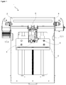
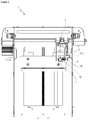
- A three-dimensional printing device realized in order to attain the aim of the present invention is illustrated in the attached figures, where:
-
Figure 1 - is the front view of the three-dimensional printing device. -
Figure 2 - is the front view of the three-dimensional printing device when the first arm contacts the first actuation member. -
Figure 3 - is the front view of the three-dimensional printing device when the electronic switch contacts the printing table. -
Figure 4 - is the front view of the three-dimensional printing device when the second arm contacts the second actuation member. - The elements illustrated in the figures are numbered as follows:
- 1. Three-dimensional printing device
- 2. Body
- 3. Printing head
- 4. Nozzle
- 5. Printing table
- 6. Calibration member
- 7. Actuation member
- 7.1- First actuation member
- 7.2- Second actuation member
- 1. Control unit
- 2. First arm
- 3. Second arm
- 4. Electronic switch
- 5. Protrusion
- 6. Housing
- 7. Return spring
- The three-dimensional printing device (1) comprises a body (2); a printing head (3) which is provided on the body (2) and which performs the printing operation; a nozzle (4) which is provided on the printing head (3) and which is used for delivering and processing the material; and a printing table (5) whereon the material leaving the nozzle (4) is delivered to form the product. The molten material is delivered onto the printing head (3) provided on the body (2). The material is sent out of the nozzle (4) provided on the printing head (3) so as to create a form. The material leaving the nozzle (4) creates the product as layers on the printing table (5).
- The three-dimensional printing device (1) of the present invention comprises a calibration member (6) which is provided on the printing head (3); a plurality of actuation members (7) which are provided on the body (2) in the vicinity of the printing head (3); and a control unit (8) which determines the position of the printing head (3) as the calibration member (7) contacts the actuation member (7) and the printing table (5). The position for production is determined as the printing head (3) contacts the actuation member (7) and the printing table (5). By means of the control unit (8), the production limits are defined. By means of the automatic calibration operation, ease of use is provided, and the first layer is delivered onto the printing table (5) more durably.
- In an embodiment of the present invention, the three-dimensional printing device (6) comprises the calibration member (6) having a first arm (9); a second arm (10) which is arranged so as to form almost a right angle with the first arm (9); and an electronic switch (11) which is provided on the side opposite to the side where the first arm (9) is positioned. The first arm (9) and the second arm (10) contact the actuation member (7) from the sides. Thus, the production operation is aligned from the sides. The electronic switch (11) sweeps the surface of the printing table (5) and determines the region where the molten material is to be formed.
- In an embodiment of the present invention, the three-dimensional printing device (1) comprises a protrusion (12) which is provided on the printing head (3) and a housing (13) which is provided on the calibration member (6) and which is fitted over the protrusion (12) so as to rotate on the protrusion (12). The housing (13) on the calibration member (6) is fitted over the protrusion (12) on the printing head (3). By means of the circular form of the protrusion (12) and the housing (13), the calibration member (6) can rotate on the printing head (3).
- In an embodiment of the present invention, the three-dimensional printing device (1) comprises a return spring (14) with one end disposed on the first arm (9) and the other end on the calibration member (6), which enables the calibration member (6) to be locked. By means of the return spring (14), the calibration member (6) is locked while rotating on the printing head (3).
- In an embodiment of the present invention, the three-dimensional printing device (1) comprises a first actuation member (7.1) which is positioned at one side of the printing head (3) and a second actuation member (7.2) which is positioned at the other side of the printing head (3). The first actuation member (7.1) is positioned at one side of the printing head (3) and the second actuation member (7.2) is positioned at the other side thereof. The first actuation member (7.1) and the second actuation member (7.2) enable the printing head (3) to be aligned from right and left.
- In an embodiment of the present invention, the three-dimensional printing device (1) comprises the control unit (8) executing an algorithm comprising the steps of moving the printing head (3) towards the first actuation member (7.1) so as to make the first arm (9) contact the first actuation member (7.1), making the printing head (3) return approximately 90 degrees on the protrusion (12) as the first arm (9) contacts the first actuation member (7.1), moving the printing table (5) towards the printing head (3) so as to make the electronic switch (11) determine the limits of the printing table (5), moving the printing head (3) towards the second actuation member (7.2) and making the second arm (10) contact the second actuation member (7.2) so as to make the calibration member (6) return to the initial position. The printing head (3) moves towards the first actuation member (7.1). As the first arm (9) contacts the first actuation member (7.1), the calibration member (6) rotates approximately 90 degrees. Upon the rotation of the calibration member (6), the electronic switch (11) is directed towards the printing table (5). By means of the electronic switch (11) sweeping the surface of the printing table (5), the production areas on the printing table (5) are determined. After the electronic switch (11) completes the sweeping operation, the printing head (3) moves towards the second actuation member (7.2), and as the second arm (10) contacts the second actuation member (7.2), the calibration member (6) returns to the initial position and the material is delivered to the printing table (5) from the nozzle (4).
- In an embodiment of the present invention, the three-dimensional printing device (1) comprises the control unit (8) which compares the size values of the printing table (5) prerecorded thereon by the producer with the values measured from the printing table (5) by means of the electronic switch (11) and determines the size and position of the printing table (5). The dimensions and inclination values of the printing table (5) for ideal production are predefined on the control unit (8) by the producer. The printing table (5) values measured by the electronic switch (11) are compared with the reference values on the control unit (8). Thus, the ideal distance between the printing head (3) and the printing table (5) is determined.
- By means of the present invention, a three-dimensional printing device (1) providing automatic calibration is realized. By automatically adjusting the positions of the printing head (3) and the printing table (5), an efficient first layer production is realized on the printing table (5). Thus, other layers can be easily added onto the first layer, providing ease of production.
Claims (7)
- A three-dimensional printing device (1) comprising a body (2); a printing head (3) which is provided on the body (2) and which performs the printing operation; a nozzle (4) which is provided on the printing head (3) and which is used for processing the material; and a printing table (5) whereon the material leaving the nozzle (4) is delivered, characterized by a calibration member (6) which is provided on the printing head (3); a plurality of actuation members (7) which are provided on the body (2) in the vicinity of the printing head (3); and a control unit (8) which determines the position of the printing head (3) as the calibration member (7) contacts the actuation member (7) and the printing table (5).
- A three-dimensional printing device (1) as in Claim 1, characterized by the calibration member (6) having a first arm (9); a second arm (10) which is arranged so as to form almost a right angle with the first arm (9); and an electronic switch (11) which is provided on the side opposite to the side where the first arm (9) is positioned.
- A three-dimensional printing device (1) as in Claim 1 and Claim 2, characterized by a protrusion (12) which is provided on the printing head (3) and a housing (13) which is provided on the calibration member (6) and which is fitted over the protrusion (12) so as to rotate on the protrusion (12).
- A three-dimensional printing device (1) as in Claim 2 or Claim 3, characterized by a return spring (14) with one end disposed on the first arm (9) and the other end on the calibration member (6), which enables the calibration member (6) to be locked.
- A three-dimensional printing device (1) as in any one of the above claims, characterized by a first actuation member (7.1) which is positioned at one side of the printing head (3) and a second actuation member (7.2) which is positioned at the other side of the printing head (3).
- A three-dimensional printing device (1) as in Claim 5, characterized by the control unit (8) executing an algorithm comprising the steps of moving the printing head (3) towards the first actuation member (7.1) so as to make the first arm (9) contact the first actuation member (7.1), making the printing head (3) return approximately 90 degrees on the protrusion (12) as the first arm (9) contacts the first actuation member (7.1), moving the printing table (5) towards the printing head (3) so as to make the electronic switch (11) determine the limits of the printing table (5), moving the printing head (3) towards the second actuation member (7.2) and making the second arm (10) contact the second actuation member (7.2) so as to make the calibration member (6) return to the initial position.
- A three-dimensional printing device (1) as in any one of the Claims 2 to 6, characterized by the control unit (8) which compares the size values of the printing table (5) prerecorded thereon by the producer with the values measured from the printing table (5) by means of the electronic switch (11) and determines the size and position of the printing table (5).
Applications Claiming Priority (1)
| Application Number | Priority Date | Filing Date | Title |
|---|---|---|---|
| TR201918551 | 2019-11-27 |
Publications (2)
| Publication Number | Publication Date |
|---|---|
| EP3827970A1 true EP3827970A1 (en) | 2021-06-02 |
| EP3827970B1 EP3827970B1 (en) | 2024-02-07 |
Family
ID=73029860
Family Applications (1)
| Application Number | Title | Priority Date | Filing Date |
|---|---|---|---|
| EP20203989.7A Active EP3827970B1 (en) | 2019-11-27 | 2020-10-27 | A three-dimensional printing device providing automatic calibration |
Country Status (1)
| Country | Link |
|---|---|
| EP (1) | EP3827970B1 (en) |
Citations (4)
| Publication number | Priority date | Publication date | Assignee | Title |
|---|---|---|---|---|
| US20070228592A1 (en) * | 2006-04-03 | 2007-10-04 | Stratasys, Inc. | Auto tip calibration in an extrusion apparatus |
| US9205690B2 (en) * | 2012-03-16 | 2015-12-08 | Stratasys, Inc. | Automated calibration method for additive manufacturing system, and method of use thereof |
| EP3135460A1 (en) | 2015-08-28 | 2017-03-01 | Ultimaker B.V. | Print bed levelling system and method for additive manufacturing |
| US9908290B1 (en) * | 2014-02-27 | 2018-03-06 | Richard A. Clayton | Configurable printers |
-
2020
- 2020-10-27 EP EP20203989.7A patent/EP3827970B1/en active Active
Patent Citations (4)
| Publication number | Priority date | Publication date | Assignee | Title |
|---|---|---|---|---|
| US20070228592A1 (en) * | 2006-04-03 | 2007-10-04 | Stratasys, Inc. | Auto tip calibration in an extrusion apparatus |
| US9205690B2 (en) * | 2012-03-16 | 2015-12-08 | Stratasys, Inc. | Automated calibration method for additive manufacturing system, and method of use thereof |
| US9908290B1 (en) * | 2014-02-27 | 2018-03-06 | Richard A. Clayton | Configurable printers |
| EP3135460A1 (en) | 2015-08-28 | 2017-03-01 | Ultimaker B.V. | Print bed levelling system and method for additive manufacturing |
Also Published As
| Publication number | Publication date |
|---|---|
| EP3827970B1 (en) | 2024-02-07 |
Similar Documents
| Publication | Publication Date | Title |
|---|---|---|
| US10328637B2 (en) | Interlayer adhesion in a part printed by additive manufacturing | |
| JP6860557B2 (en) | Powder supply for additional manufacturing | |
| JP6485617B2 (en) | Three-dimensional printing method for arranging filaments horizontally without support | |
| EP3345735B1 (en) | Method of printing on a 3d jet printer | |
| US10974495B2 (en) | Thermal management methods and apparatus for producing uniform material deposition and curing for high speed three-dimensional printing | |
| EP3235355B1 (en) | 3d ink jet printing method | |
| GB2521396A (en) | A machine for grinding a work-piece | |
| KR102472009B1 (en) | Apparatus and a method for forming 3d objects | |
| CN108723364B (en) | Powder Supply Device for 3D Shape Manufacturing | |
| WO2019128265A1 (en) | Multi-nozzle compacting 3d printer and printing method thereof | |
| EP3827970B1 (en) | A three-dimensional printing device providing automatic calibration | |
| CN112045994A (en) | Additive manufacturing system and method of additive manufacturing | |
| EP3083212B1 (en) | Method for printing a three-dimensional light-guiding structure | |
| KR102018537B1 (en) | 3D Printer Nozzle Structure | |
| EP3878581A1 (en) | Method and system for operating a modular heater to improve layer bonding in a metal drop ejecting three-dimensional (3d) object printer | |
| US10603837B2 (en) | Belt leveling of layers in a part printed by additive manufacturing | |
| EP3486069A1 (en) | Extrusion nozzle for three-dimensional printing | |
| CN106042379B (en) | 3D printing head, 3D printer and 3D printing method thereof | |
| JP2019155885A (en) | Three-dimensional molding apparatus | |
| WO2019006071A1 (en) | Determining start position in three-dimensional printers | |
| KR101662501B1 (en) | Three-dimensional printer | |
| CN214164045U (en) | 3D beats printer head and 3D printer | |
| KR101512766B1 (en) | Solder paste dispenser | |
| KR20190091247A (en) | 3D Printer Nozzle Structure | |
| CN112721159A (en) | 3D printing head, 3D printer and control method of 3D printer |
Legal Events
| Date | Code | Title | Description |
|---|---|---|---|
| PUAI | Public reference made under article 153(3) epc to a published international application that has entered the european phase |
Free format text: ORIGINAL CODE: 0009012 |
|
| STAA | Information on the status of an ep patent application or granted ep patent |
Free format text: STATUS: REQUEST FOR EXAMINATION WAS MADE |
|
| 17P | Request for examination filed |
Effective date: 20201027 |
|
| AK | Designated contracting states |
Kind code of ref document: A1 Designated state(s): AL AT BE BG CH CY CZ DE DK EE ES FI FR GB GR HR HU IE IS IT LI LT LU LV MC MK MT NL NO PL PT RO RS SE SI SK SM TR |
|
| GRAP | Despatch of communication of intention to grant a patent |
Free format text: ORIGINAL CODE: EPIDOSNIGR1 |
|
| STAA | Information on the status of an ep patent application or granted ep patent |
Free format text: STATUS: GRANT OF PATENT IS INTENDED |
|
| RIC1 | Information provided on ipc code assigned before grant |
Ipc: B29C 64/30 20170101ALI20230929BHEP Ipc: B33Y 30/00 20150101ALI20230929BHEP Ipc: B33Y 50/02 20150101ALI20230929BHEP Ipc: B33Y 40/00 20200101ALI20230929BHEP Ipc: B29C 64/393 20170101ALI20230929BHEP Ipc: B29C 64/25 20170101ALI20230929BHEP Ipc: B22F 10/31 20210101ALI20230929BHEP Ipc: B29C 64/209 20170101AFI20230929BHEP |
|
| INTG | Intention to grant announced |
Effective date: 20231026 |
|
| GRAS | Grant fee paid |
Free format text: ORIGINAL CODE: EPIDOSNIGR3 |
|
| GRAA | (expected) grant |
Free format text: ORIGINAL CODE: 0009210 |
|
| STAA | Information on the status of an ep patent application or granted ep patent |
Free format text: STATUS: THE PATENT HAS BEEN GRANTED |
|
| AK | Designated contracting states |
Kind code of ref document: B1 Designated state(s): AL AT BE BG CH CY CZ DE DK EE ES FI FR GB GR HR HU IE IS IT LI LT LU LV MC MK MT NL NO PL PT RO RS SE SI SK SM TR |
|
| REG | Reference to a national code |
Ref country code: GB Ref legal event code: FG4D |
|
| REG | Reference to a national code |
Ref country code: CH Ref legal event code: EP |
|
| REG | Reference to a national code |
Ref country code: DE Ref legal event code: R096 Ref document number: 602020025262 Country of ref document: DE |
|
| REG | Reference to a national code |
Ref country code: IE Ref legal event code: FG4D |
|
| REG | Reference to a national code |
Ref country code: LT Ref legal event code: MG9D |
|
| REG | Reference to a national code |
Ref country code: NL Ref legal event code: MP Effective date: 20240207 |
|
| PG25 | Lapsed in a contracting state [announced via postgrant information from national office to epo] |
Ref country code: IS Free format text: LAPSE BECAUSE OF FAILURE TO SUBMIT A TRANSLATION OF THE DESCRIPTION OR TO PAY THE FEE WITHIN THE PRESCRIBED TIME-LIMIT Effective date: 20240607 |
|
| PG25 | Lapsed in a contracting state [announced via postgrant information from national office to epo] |
Ref country code: LT Free format text: LAPSE BECAUSE OF FAILURE TO SUBMIT A TRANSLATION OF THE DESCRIPTION OR TO PAY THE FEE WITHIN THE PRESCRIBED TIME-LIMIT Effective date: 20240207 |
|
| PG25 | Lapsed in a contracting state [announced via postgrant information from national office to epo] |
Ref country code: GR Free format text: LAPSE BECAUSE OF FAILURE TO SUBMIT A TRANSLATION OF THE DESCRIPTION OR TO PAY THE FEE WITHIN THE PRESCRIBED TIME-LIMIT Effective date: 20240508 |
|
| REG | Reference to a national code |
Ref country code: AT Ref legal event code: MK05 Ref document number: 1655107 Country of ref document: AT Kind code of ref document: T Effective date: 20240207 |
|
| PG25 | Lapsed in a contracting state [announced via postgrant information from national office to epo] |
Ref country code: RS Free format text: LAPSE BECAUSE OF FAILURE TO SUBMIT A TRANSLATION OF THE DESCRIPTION OR TO PAY THE FEE WITHIN THE PRESCRIBED TIME-LIMIT Effective date: 20240507 Ref country code: HR Free format text: LAPSE BECAUSE OF FAILURE TO SUBMIT A TRANSLATION OF THE DESCRIPTION OR TO PAY THE FEE WITHIN THE PRESCRIBED TIME-LIMIT Effective date: 20240207 Ref country code: NL Free format text: LAPSE BECAUSE OF FAILURE TO SUBMIT A TRANSLATION OF THE DESCRIPTION OR TO PAY THE FEE WITHIN THE PRESCRIBED TIME-LIMIT Effective date: 20240207 |
|
| PG25 | Lapsed in a contracting state [announced via postgrant information from national office to epo] |
Ref country code: ES Free format text: LAPSE BECAUSE OF FAILURE TO SUBMIT A TRANSLATION OF THE DESCRIPTION OR TO PAY THE FEE WITHIN THE PRESCRIBED TIME-LIMIT Effective date: 20240207 |
|
| PG25 | Lapsed in a contracting state [announced via postgrant information from national office to epo] |
Ref country code: AT Free format text: LAPSE BECAUSE OF FAILURE TO SUBMIT A TRANSLATION OF THE DESCRIPTION OR TO PAY THE FEE WITHIN THE PRESCRIBED TIME-LIMIT Effective date: 20240207 |
|
| PG25 | Lapsed in a contracting state [announced via postgrant information from national office to epo] |
Ref country code: RS Free format text: LAPSE BECAUSE OF FAILURE TO SUBMIT A TRANSLATION OF THE DESCRIPTION OR TO PAY THE FEE WITHIN THE PRESCRIBED TIME-LIMIT Effective date: 20240507 Ref country code: NO Free format text: LAPSE BECAUSE OF FAILURE TO SUBMIT A TRANSLATION OF THE DESCRIPTION OR TO PAY THE FEE WITHIN THE PRESCRIBED TIME-LIMIT Effective date: 20240507 Ref country code: NL Free format text: LAPSE BECAUSE OF FAILURE TO SUBMIT A TRANSLATION OF THE DESCRIPTION OR TO PAY THE FEE WITHIN THE PRESCRIBED TIME-LIMIT Effective date: 20240207 Ref country code: LT Free format text: LAPSE BECAUSE OF FAILURE TO SUBMIT A TRANSLATION OF THE DESCRIPTION OR TO PAY THE FEE WITHIN THE PRESCRIBED TIME-LIMIT Effective date: 20240207 Ref country code: IS Free format text: LAPSE BECAUSE OF FAILURE TO SUBMIT A TRANSLATION OF THE DESCRIPTION OR TO PAY THE FEE WITHIN THE PRESCRIBED TIME-LIMIT Effective date: 20240607 Ref country code: HR Free format text: LAPSE BECAUSE OF FAILURE TO SUBMIT A TRANSLATION OF THE DESCRIPTION OR TO PAY THE FEE WITHIN THE PRESCRIBED TIME-LIMIT Effective date: 20240207 Ref country code: GR Free format text: LAPSE BECAUSE OF FAILURE TO SUBMIT A TRANSLATION OF THE DESCRIPTION OR TO PAY THE FEE WITHIN THE PRESCRIBED TIME-LIMIT Effective date: 20240508 Ref country code: FI Free format text: LAPSE BECAUSE OF FAILURE TO SUBMIT A TRANSLATION OF THE DESCRIPTION OR TO PAY THE FEE WITHIN THE PRESCRIBED TIME-LIMIT Effective date: 20240207 Ref country code: ES Free format text: LAPSE BECAUSE OF FAILURE TO SUBMIT A TRANSLATION OF THE DESCRIPTION OR TO PAY THE FEE WITHIN THE PRESCRIBED TIME-LIMIT Effective date: 20240207 Ref country code: BG Free format text: LAPSE BECAUSE OF FAILURE TO SUBMIT A TRANSLATION OF THE DESCRIPTION OR TO PAY THE FEE WITHIN THE PRESCRIBED TIME-LIMIT Effective date: 20240207 Ref country code: AT Free format text: LAPSE BECAUSE OF FAILURE TO SUBMIT A TRANSLATION OF THE DESCRIPTION OR TO PAY THE FEE WITHIN THE PRESCRIBED TIME-LIMIT Effective date: 20240207 |
|
| PG25 | Lapsed in a contracting state [announced via postgrant information from national office to epo] |
Ref country code: PL Free format text: LAPSE BECAUSE OF FAILURE TO SUBMIT A TRANSLATION OF THE DESCRIPTION OR TO PAY THE FEE WITHIN THE PRESCRIBED TIME-LIMIT Effective date: 20240207 Ref country code: PT Free format text: LAPSE BECAUSE OF FAILURE TO SUBMIT A TRANSLATION OF THE DESCRIPTION OR TO PAY THE FEE WITHIN THE PRESCRIBED TIME-LIMIT Effective date: 20240607 |
|
| PG25 | Lapsed in a contracting state [announced via postgrant information from national office to epo] |
Ref country code: SE Free format text: LAPSE BECAUSE OF FAILURE TO SUBMIT A TRANSLATION OF THE DESCRIPTION OR TO PAY THE FEE WITHIN THE PRESCRIBED TIME-LIMIT Effective date: 20240207 Ref country code: PT Free format text: LAPSE BECAUSE OF FAILURE TO SUBMIT A TRANSLATION OF THE DESCRIPTION OR TO PAY THE FEE WITHIN THE PRESCRIBED TIME-LIMIT Effective date: 20240607 Ref country code: PL Free format text: LAPSE BECAUSE OF FAILURE TO SUBMIT A TRANSLATION OF THE DESCRIPTION OR TO PAY THE FEE WITHIN THE PRESCRIBED TIME-LIMIT Effective date: 20240207 Ref country code: LV Free format text: LAPSE BECAUSE OF FAILURE TO SUBMIT A TRANSLATION OF THE DESCRIPTION OR TO PAY THE FEE WITHIN THE PRESCRIBED TIME-LIMIT Effective date: 20240207 |
|
| PG25 | Lapsed in a contracting state [announced via postgrant information from national office to epo] |
Ref country code: DK Free format text: LAPSE BECAUSE OF FAILURE TO SUBMIT A TRANSLATION OF THE DESCRIPTION OR TO PAY THE FEE WITHIN THE PRESCRIBED TIME-LIMIT Effective date: 20240207 |
|
| PG25 | Lapsed in a contracting state [announced via postgrant information from national office to epo] |
Ref country code: SM Free format text: LAPSE BECAUSE OF FAILURE TO SUBMIT A TRANSLATION OF THE DESCRIPTION OR TO PAY THE FEE WITHIN THE PRESCRIBED TIME-LIMIT Effective date: 20240207 |
|
| PG25 | Lapsed in a contracting state [announced via postgrant information from national office to epo] |
Ref country code: CZ Free format text: LAPSE BECAUSE OF FAILURE TO SUBMIT A TRANSLATION OF THE DESCRIPTION OR TO PAY THE FEE WITHIN THE PRESCRIBED TIME-LIMIT Effective date: 20240207 Ref country code: EE Free format text: LAPSE BECAUSE OF FAILURE TO SUBMIT A TRANSLATION OF THE DESCRIPTION OR TO PAY THE FEE WITHIN THE PRESCRIBED TIME-LIMIT Effective date: 20240207 |
|
| PG25 | Lapsed in a contracting state [announced via postgrant information from national office to epo] |
Ref country code: SK Free format text: LAPSE BECAUSE OF FAILURE TO SUBMIT A TRANSLATION OF THE DESCRIPTION OR TO PAY THE FEE WITHIN THE PRESCRIBED TIME-LIMIT Effective date: 20240207 |
|
| PG25 | Lapsed in a contracting state [announced via postgrant information from national office to epo] |
Ref country code: SM Free format text: LAPSE BECAUSE OF FAILURE TO SUBMIT A TRANSLATION OF THE DESCRIPTION OR TO PAY THE FEE WITHIN THE PRESCRIBED TIME-LIMIT Effective date: 20240207 Ref country code: SK Free format text: LAPSE BECAUSE OF FAILURE TO SUBMIT A TRANSLATION OF THE DESCRIPTION OR TO PAY THE FEE WITHIN THE PRESCRIBED TIME-LIMIT Effective date: 20240207 Ref country code: RO Free format text: LAPSE BECAUSE OF FAILURE TO SUBMIT A TRANSLATION OF THE DESCRIPTION OR TO PAY THE FEE WITHIN THE PRESCRIBED TIME-LIMIT Effective date: 20240207 Ref country code: EE Free format text: LAPSE BECAUSE OF FAILURE TO SUBMIT A TRANSLATION OF THE DESCRIPTION OR TO PAY THE FEE WITHIN THE PRESCRIBED TIME-LIMIT Effective date: 20240207 Ref country code: DK Free format text: LAPSE BECAUSE OF FAILURE TO SUBMIT A TRANSLATION OF THE DESCRIPTION OR TO PAY THE FEE WITHIN THE PRESCRIBED TIME-LIMIT Effective date: 20240207 Ref country code: CZ Free format text: LAPSE BECAUSE OF FAILURE TO SUBMIT A TRANSLATION OF THE DESCRIPTION OR TO PAY THE FEE WITHIN THE PRESCRIBED TIME-LIMIT Effective date: 20240207 |
|
| REG | Reference to a national code |
Ref country code: DE Ref legal event code: R097 Ref document number: 602020025262 Country of ref document: DE |
|
| PG25 | Lapsed in a contracting state [announced via postgrant information from national office to epo] |
Ref country code: IT Free format text: LAPSE BECAUSE OF FAILURE TO SUBMIT A TRANSLATION OF THE DESCRIPTION OR TO PAY THE FEE WITHIN THE PRESCRIBED TIME-LIMIT Effective date: 20240207 |
|
| PLBE | No opposition filed within time limit |
Free format text: ORIGINAL CODE: 0009261 |
|
| STAA | Information on the status of an ep patent application or granted ep patent |
Free format text: STATUS: NO OPPOSITION FILED WITHIN TIME LIMIT |
|
| PG25 | Lapsed in a contracting state [announced via postgrant information from national office to epo] |
Ref country code: IT Free format text: LAPSE BECAUSE OF FAILURE TO SUBMIT A TRANSLATION OF THE DESCRIPTION OR TO PAY THE FEE WITHIN THE PRESCRIBED TIME-LIMIT Effective date: 20240207 |
|
| 26N | No opposition filed |
Effective date: 20241108 |
|
| PG25 | Lapsed in a contracting state [announced via postgrant information from national office to epo] |
Ref country code: SI Free format text: LAPSE BECAUSE OF FAILURE TO SUBMIT A TRANSLATION OF THE DESCRIPTION OR TO PAY THE FEE WITHIN THE PRESCRIBED TIME-LIMIT Effective date: 20240207 |
|
| REG | Reference to a national code |
Ref country code: CH Ref legal event code: PL |
|
| PG25 | Lapsed in a contracting state [announced via postgrant information from national office to epo] |
Ref country code: MC Free format text: LAPSE BECAUSE OF FAILURE TO SUBMIT A TRANSLATION OF THE DESCRIPTION OR TO PAY THE FEE WITHIN THE PRESCRIBED TIME-LIMIT Effective date: 20240207 |
|
| PG25 | Lapsed in a contracting state [announced via postgrant information from national office to epo] |
Ref country code: BE Free format text: LAPSE BECAUSE OF NON-PAYMENT OF DUE FEES Effective date: 20241031 Ref country code: LU Free format text: LAPSE BECAUSE OF NON-PAYMENT OF DUE FEES Effective date: 20241027 |
|
| PG25 | Lapsed in a contracting state [announced via postgrant information from national office to epo] |
Ref country code: CH Free format text: LAPSE BECAUSE OF NON-PAYMENT OF DUE FEES Effective date: 20241031 |
|
| REG | Reference to a national code |
Ref country code: BE Ref legal event code: MM Effective date: 20241031 |
|
| PG25 | Lapsed in a contracting state [announced via postgrant information from national office to epo] |
Ref country code: IE Free format text: LAPSE BECAUSE OF NON-PAYMENT OF DUE FEES Effective date: 20241027 |
|
| PGFP | Annual fee paid to national office [announced via postgrant information from national office to epo] |
Ref country code: DE Payment date: 20251021 Year of fee payment: 6 |
|
| PGFP | Annual fee paid to national office [announced via postgrant information from national office to epo] |
Ref country code: GB Payment date: 20251022 Year of fee payment: 6 |
|
| PGFP | Annual fee paid to national office [announced via postgrant information from national office to epo] |
Ref country code: FR Payment date: 20251030 Year of fee payment: 6 |
|
| PGFP | Annual fee paid to national office [announced via postgrant information from national office to epo] |
Ref country code: TR Payment date: 20251016 Year of fee payment: 6 |
|
| PG25 | Lapsed in a contracting state [announced via postgrant information from national office to epo] |
Ref country code: CY Free format text: LAPSE BECAUSE OF FAILURE TO SUBMIT A TRANSLATION OF THE DESCRIPTION OR TO PAY THE FEE WITHIN THE PRESCRIBED TIME-LIMIT; INVALID AB INITIO Effective date: 20201027 |
|
| PG25 | Lapsed in a contracting state [announced via postgrant information from national office to epo] |
Ref country code: HU Free format text: LAPSE BECAUSE OF FAILURE TO SUBMIT A TRANSLATION OF THE DESCRIPTION OR TO PAY THE FEE WITHIN THE PRESCRIBED TIME-LIMIT; INVALID AB INITIO Effective date: 20201027 |