EP3827924A1 - Assembly apparatus - Google Patents
Assembly apparatus Download PDFInfo
- Publication number
- EP3827924A1 EP3827924A1 EP20200739.9A EP20200739A EP3827924A1 EP 3827924 A1 EP3827924 A1 EP 3827924A1 EP 20200739 A EP20200739 A EP 20200739A EP 3827924 A1 EP3827924 A1 EP 3827924A1
- Authority
- EP
- European Patent Office
- Prior art keywords
- assembly
- steel material
- shaped steel
- coupling hole
- coordinates
- Prior art date
- Legal status (The legal status is an assumption and is not a legal conclusion. Google has not performed a legal analysis and makes no representation as to the accuracy of the status listed.)
- Pending
Links
- 230000008878 coupling Effects 0.000 claims abstract description 54
- 238000010168 coupling process Methods 0.000 claims abstract description 54
- 238000005859 coupling reaction Methods 0.000 claims abstract description 54
- 238000003754 machining Methods 0.000 claims abstract description 39
- 238000005259 measurement Methods 0.000 claims abstract description 24
- 239000000463 material Substances 0.000 description 63
- 229910000831 Steel Inorganic materials 0.000 description 62
- 239000010959 steel Substances 0.000 description 62
- 238000005553 drilling Methods 0.000 description 20
- 230000004048 modification Effects 0.000 description 11
- 238000012986 modification Methods 0.000 description 11
- 230000000052 comparative effect Effects 0.000 description 7
- 230000009467 reduction Effects 0.000 description 4
- 230000000717 retained effect Effects 0.000 description 4
- 230000004075 alteration Effects 0.000 description 2
- 230000006870 function Effects 0.000 description 2
- 238000000034 method Methods 0.000 description 2
- 230000015572 biosynthetic process Effects 0.000 description 1
- 238000006073 displacement reaction Methods 0.000 description 1
- 230000000694 effects Effects 0.000 description 1
- 230000001678 irradiating effect Effects 0.000 description 1
Images




Classifications
-
- B—PERFORMING OPERATIONS; TRANSPORTING
- B23—MACHINE TOOLS; METAL-WORKING NOT OTHERWISE PROVIDED FOR
- B23P—METAL-WORKING NOT OTHERWISE PROVIDED FOR; COMBINED OPERATIONS; UNIVERSAL MACHINE TOOLS
- B23P19/00—Machines for simply fitting together or separating metal parts or objects, or metal and non-metal parts, whether or not involving some deformation; Tools or devices therefor so far as not provided for in other classes
- B23P19/10—Aligning parts to be fitted together
-
- B—PERFORMING OPERATIONS; TRANSPORTING
- B23—MACHINE TOOLS; METAL-WORKING NOT OTHERWISE PROVIDED FOR
- B23Q—DETAILS, COMPONENTS, OR ACCESSORIES FOR MACHINE TOOLS, e.g. ARRANGEMENTS FOR COPYING OR CONTROLLING; MACHINE TOOLS IN GENERAL CHARACTERISED BY THE CONSTRUCTION OF PARTICULAR DETAILS OR COMPONENTS; COMBINATIONS OR ASSOCIATIONS OF METAL-WORKING MACHINES, NOT DIRECTED TO A PARTICULAR RESULT
- B23Q15/00—Automatic control or regulation of feed movement, cutting velocity or position of tool or work
- B23Q15/007—Automatic control or regulation of feed movement, cutting velocity or position of tool or work while the tool acts upon the workpiece
- B23Q15/013—Control or regulation of feed movement
- B23Q15/06—Control or regulation of feed movement according to measuring results produced by two or more gauging methods using different measuring principles, e.g. by both optical and mechanical gauging
-
- B—PERFORMING OPERATIONS; TRANSPORTING
- B23—MACHINE TOOLS; METAL-WORKING NOT OTHERWISE PROVIDED FOR
- B23B—TURNING; BORING
- B23B35/00—Methods for boring or drilling, or for working essentially requiring the use of boring or drilling machines; Use of auxiliary equipment in connection with such methods
-
- B—PERFORMING OPERATIONS; TRANSPORTING
- B23—MACHINE TOOLS; METAL-WORKING NOT OTHERWISE PROVIDED FOR
- B23B—TURNING; BORING
- B23B49/00—Measuring or gauging equipment on boring machines for positioning or guiding the drill; Devices for indicating failure of drills during boring; Centering devices for holes to be bored
-
- B—PERFORMING OPERATIONS; TRANSPORTING
- B64—AIRCRAFT; AVIATION; COSMONAUTICS
- B64C—AEROPLANES; HELICOPTERS
- B64C1/00—Fuselages; Constructional features common to fuselages, wings, stabilising surfaces or the like
- B64C1/26—Attaching the wing or tail units or stabilising surfaces
-
- B—PERFORMING OPERATIONS; TRANSPORTING
- B64—AIRCRAFT; AVIATION; COSMONAUTICS
- B64F—GROUND OR AIRCRAFT-CARRIER-DECK INSTALLATIONS SPECIALLY ADAPTED FOR USE IN CONNECTION WITH AIRCRAFT; DESIGNING, MANUFACTURING, ASSEMBLING, CLEANING, MAINTAINING OR REPAIRING AIRCRAFT, NOT OTHERWISE PROVIDED FOR; HANDLING, TRANSPORTING, TESTING OR INSPECTING AIRCRAFT COMPONENTS, NOT OTHERWISE PROVIDED FOR
- B64F5/00—Designing, manufacturing, assembling, cleaning, maintaining or repairing aircraft, not otherwise provided for; Handling, transporting, testing or inspecting aircraft components, not otherwise provided for
- B64F5/10—Manufacturing or assembling aircraft, e.g. jigs therefor
-
- B—PERFORMING OPERATIONS; TRANSPORTING
- B23—MACHINE TOOLS; METAL-WORKING NOT OTHERWISE PROVIDED FOR
- B23B—TURNING; BORING
- B23B2215/00—Details of workpieces
- B23B2215/04—Aircraft components
-
- B—PERFORMING OPERATIONS; TRANSPORTING
- B23—MACHINE TOOLS; METAL-WORKING NOT OTHERWISE PROVIDED FOR
- B23P—METAL-WORKING NOT OTHERWISE PROVIDED FOR; COMBINED OPERATIONS; UNIVERSAL MACHINE TOOLS
- B23P2700/00—Indexing scheme relating to the articles being treated, e.g. manufactured, repaired, assembled, connected or other operations covered in the subgroups
- B23P2700/01—Aircraft parts
-
- B—PERFORMING OPERATIONS; TRANSPORTING
- B64—AIRCRAFT; AVIATION; COSMONAUTICS
- B64C—AEROPLANES; HELICOPTERS
- B64C3/00—Wings
- B64C3/18—Spars; Ribs; Stringers
- B64C3/185—Spars
Definitions
- the invention relates to an assembly apparatus.
- a center wing of an aircraft includes a plurality of shaped steel materials having webs and flanges.
- Japanese Unexamined Patent Application Publication JP 2016-175 157 A discloses a drilling machine that drills a hole in a shaped steel material.
- An aspect of the invention provides an assembly apparatus including a retainer, a position measurement device, and a machining device.
- the retainer is configured to hold an assembly.
- the position measurement device is configured to measure a difference between an intended machining position and an actual machining position of a first coupling hole in a first assembly component.
- the first coupling hole is capable of being coupled to the assembly.
- the machining device is configured to form a second coupling hole capable of communicating with the first coupling hole in the assembly on a basis of a reference position set on the assembly and the difference.
- a center wing is retained and positioned with jigs when a hole is drilled in a shaped steel material with a drilling machine.
- the jigs that retain and position the center wing are very expensive. Therefore, it is desirable to achieve both a reduction in the number of jigs and high assembly accuracy.
- FIG. 1 is a schematic perspective view of an aircraft 1.
- the aircraft 1 includes a fuselage 3, a pair of main wings 5, a pair of horizontal tails 7, a vertical tail 9, and a center wing 11.
- the main wings 5, the horizontal tails 7, the vertical tail 9, and the center wing 11 may be referred to simply as wings and tails.
- the fuselage 3 extends in a roll axis direction, which is the direction of a roll axis that connects nose and tail ends of the aircraft 1.
- the main wings 5 are provided at the center of the fuselage 3 in the roll axis direction.
- the main wings 5 are arranged in a pitch axis direction, which is orthogonal to the roll axis direction, and provided on the left and right sides of the fuselage 3.
- the main wings 5 extend outward from the fuselage 3 in the pitch axis direction.
- the main wings 5 have generates vertically upward lift for the aircraft 1.
- the horizontal tails 7 are disposed closer to the tail end of the fuselage 3 than the main wings 5 are.
- the horizontal tails 7 are arranged in the pitch axis direction and provided on the left and right sides of the fuselage 3.
- the horizontal tails 7 extend outward from the fuselage 3 in the pitch axis direction.
- the horizontal tails 7 ensures stability of the aircraft 1 around the pitch axis.
- the vertical tail 9 is disposed closer to the tail end of the fuselage 3 than the main wings 5 are.
- the vertical tail 9 extends outward from the fuselage 3 in a yaw axis direction, which is orthogonal to the roll axis direction and the pitch axis direction.
- the vertical tail 9 has ensures stability of the aircraft 1 around the yaw axis.
- the center wing 11 is disposed (mounted) in the fuselage 3.
- a cabin floor for example, is disposed vertically above the center wing 11, and a lower surface of the fuselage 3 is disposed vertically below the center wing 11.
- the center wing 11 is provided at the center of the fuselage 3 in the roll axis direction.
- the center wing 11 is coupled to the left and right main wings 5, and functions as portions of the main wings 5.
- the center wing 11 reduces deformation of the main wings 5 due to the lift.
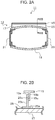
- FIG. 2A and FIG. 2B schematically illustrate the structure of the center wing 11.
- FIG. 2A is a schematic sectional view of the center wing 11 illustrated in FIG. 1 taken along line IIA-IIA.
- FIG. 2B is a schematic sectional view taken along line IIB-IIB in FIG. 2A .
- the center wing 11 includes an assembly 13 and a first shaped steel material (first assembly component) 15.
- the center wing 11 has an integral structure including the assembly 13 and the first shaped steel material 15 and formed by fastening the assembly 13 and the first shaped steel material 15 together with fastening members (not illustrated), such as bolts.
- the cabin floor for example, is placed vertically above the first shaped steel material 15.
- the assembly 13 has a box structure formed by assembling a plurality of assembly components.
- the assembly 13 includes an upper panel 17, a lower panel 19, a front spar 21, a rear spar 23, and a second shaped steel material (second assembly component) 25.
- the upper panel 17, which is a plate-shaped member, is disposed to face the lower panel 19 in the vertical direction.
- the lower panel 19, which is also a plate-shaped member, is disposed vertically below the upper panel 17.
- the upper panel 17 and the lower panel 19 are curved in this embodiment, but may instead be flat.
- the front spar 21 and the rear spar 23 are disposed between the upper panel 17 and the lower panel 19.
- the rear spar 23, which is also a plate-shaped member, is disposed closer to the tail end than the front spar 21 is in the roll axis direction.
- the front spar 21 is coupled to the upper panel 17 and the lower panel 19 by coupling members, and the rear spar 23 is also coupled to the upper panel 17 and the lower panel 19 by coupling members.
- the upper panel 17, the lower panel 19, the front spar 21, and the rear spar 23 are brought together to form a box shape.
- the second shaped steel material 25 is positioned vertically above the upper panel 17, and is fixed to the upper surface of the upper panel 17. As illustrated in FIG. 2B , the second shaped steel material 25 is T-shaped and includes a flange 25a and a web 25b. The flange 25a is coupled to the upper panel 17, and the web 25b extends from the flange 25a in a direction away from the upper panel 17. The web 25b has a coupling hole (second coupling hole) 25c. The coupling hole 25c extends through the web 25b in the thickness direction.
- the flange 25a and the web 25b extend in the direction from the near side to the far side of FIG. 2B .
- the second shaped steel material 25 extends between the front spar 21 and the rear spar 23 in the roll axis direction.
- the first shaped steel material 15 is positioned vertically above the flange 25a of the second shaped steel material 25. As illustrated in FIG. 2B , the first shaped steel material 15 is T-shaped, and the shape thereof is similar to that of the second shaped steel material 25.
- the first shaped steel material 15 includes a flange 15a and a web 15b.
- the flange 15a is disposed to face the flange 25a of the second shaped steel material 25 in the vertical direction.
- the web 15b extends from the flange 15a in a direction toward the upper panel 17.
- the web 15b is disposed such that at least a portion thereof overlaps the web 25b of the second shaped steel material 25 in the thickness direction (left-right direction in FIG. 2B ).
- the web 15b has a coupling hole (first coupling hole) 15c. The coupling hole 15c extends through the web 15b in the thickness direction.
- the flange 15a and the web 15b extend in the direction from the near side to the far side of FIG. 2B .
- the first shaped steel material 15 extends between the front spar 21 and the rear spar 23 in the roll axis direction.
- the coupling holes 15c and 25c are disposed to face each other in the thickness direction of the webs 15b and 25b.
- a fastening member (not illustrated) is inserted through the coupling holes 15c and 25c to fasten the first shaped steel material 15 and the second shaped steel material 25 (assembly 13) together.
- the center wing 11 is assembled.
- FIG. 3A and FIG. 3B schematically illustrate the structure of the assembly apparatus 50 according to the comparative example.
- FIG. 3A schematically illustrates the structure of the assembly apparatus 50 before the coupling hole 25c is formed in the second shaped steel material 25
- FIG. 3B is a schematic sectional view taken along line IIIB-IIIB in FIG. 3A .
- the assembly apparatus 50 includes a lower jig 51, an upper jig 53, and a drilling machine (not illustrated).
- the lower jig 51 is disposed vertically below the lower panel 19.
- the lower jig 51 retains the assembly 13 in an assembling position at a location vertically below the lower panel 19.
- the upper jig 53 is disposed vertically above the first shaped steel material 15.
- the upper jig 53 retains the first shaped steel material 15 in an assembling position at a location vertically above the first shaped steel material 15.
- the lower jig 51 has coordinates L1, L2, and L3 for the design shape (design values) of the center wing 11 (assembly 13).
- the lower jig 51 retains the assembly 13 so that the lower surface of the lower panel 19 is positioned at the coordinates L1, L2, and L3 and that intended positional accuracy of the coordinates L1, L2, and L3 can be achieved.
- the upper jig 53 has coordinates U1, U2, and U3 for the design shape (design values) of the center wing 11 (first shaped steel material 15).
- the upper jig 53 retains the first shaped steel material 15 so that the upper surface of the first shaped steel material 15 is positioned at the coordinates U1, U2, and U3 and that intended positional accuracy of the coordinates U1, U2, and U3 is achieved.
- the drilling machine forms (drills) the coupling hole 25c in the second shaped steel material 25 while the assembly 13 is retained by the lower jig 51 in the assembling position and the first shaped steel material 15 is retained by the upper jig 53 in the assembling position.
- the drilling machine forms the coupling hole 25c in the second shaped steel material 25 while the lower surface of the lower panel 19 is positioned at the coordinates L1, L2, and L3 and the upper surface of the first shaped steel material 15 is positioned at the coordinates U1, U2, and U3.
- the coupling hole 15c is formed in the first shaped steel material 15.
- the drilling machine (not illustrated) forms the coupling hole 25c illustrated in FIG. 2B in the second shaped steel material 25 by inserting a drilling tool (not illustrated) through the coupling hole 15c and moving the drilling tool along a central axis AX1 of the coupling hole 15c.
- the assembly apparatus 50 fastens the first shaped steel material 15 and the second shaped steel material 25 (assembly 13) together by inserting a fastening member (not illustrated) through the coupling holes 15c and 25c. Thus, assembly of the center wing 11 is completed.
- the assembly apparatus 50 assembles the center wing 11 while the intended positional accuracy of each of the coordinates L1, L2, L3, U1, U2, and U3 is achieved by the jigs. Accordingly, the center wing 11 can be structured such that the intended positional accuracy of each coordinate is achieved.
- the lower jig 51 and the upper jig 53 used to achieve the intended positional accuracy of each coordinate are very expensive, and it is desirable to reduce the number of jigs.
- the center wing 11 is assembled without using the jigs by using the assembly components as references, since the assembly components have allowable component errors and allowable assembly errors, it is difficult to achieve the intended positional accuracy of each coordinate, and the assembly accuracy is reduced. Thus, according to the comparative example, it is difficult to achieve both a reduction in the number of jigs and high assembly accuracy.
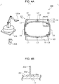
- FIG. 4A and FIG. 4B schematically illustrate the structure of the assembly apparatus 100 according to the embodiment.
- FIG. 4A schematically illustrates the structure of the assembly apparatus 100 before the coupling hole 25c is formed in the second shaped steel material 25, and
- FIG. 4B is a schematic sectional view taken along line IVB-IVB in FIG. 4A .
- the assembly apparatus 100 includes a retainer 101, a machining device 103, and a position measurement device 105.
- the retainer 101 is, for example, a jig that is disposed vertically below the lower panel 19.
- the retainer 101 retains the assembly 13 in an assembling position at a location vertically below the lower panel 19.
- the retainer 101 has coordinates (reference positions) L1, L2, and L3 for the design shape (design values) of the center wing 11 (assembly 13).
- the retainer 101 retains the assembly 13 so that the lower surface of the lower panel 19 is positioned at the coordinates L1, L2, and L3 and that intended positional accuracy of the coordinates L1, L2, and L3 can be achieved.
- the machining device 103 is, for example, a drilling machine and includes a drilling tool (tool) 103a.
- the machining device 103 forms the coupling hole (through hole) 25c in the second shaped steel material 25 by rotating the drilling tool 103a with a motor (not illustrated).
- the position measurement device 105 is, for example, a three-dimensional position measurement device that acquires three-dimensional position information by irradiating a three-dimensional object with laser light and measuring the amount of light reflected by the object.
- the position measurement device 105 measures the tool position of the drilling tool 103a of the machining device 103 and the coordinates L1, L2, and L3 of the retainer 101.
- the machining device 103 controls the position of the drilling tool 103a based on the three-dimensional position information acquired by the position measurement device 105.
- the second shaped steel material 25 of this embodiment has an excess portion 25d.
- the second shaped steel material 25 of this embodiment is shaped such that the length of the web 25b in the vertical direction is greater than the length of the web 25b of the comparative example in the vertical direction by the length of the excess portion 25d.
- FIG. 5A and FIG. 5B illustrate a method for assembling the center wing 11 of this embodiment.
- FIG. 5A illustrates measurement of the amount of displacement of the coupling hole 15c in the first shaped steel material 15 by the position measurement device 105.
- FIG. 5B illustrates formation of the coupling hole 25c in the second shaped steel material 25 by the machining device 103.
- the position measurement device 105 measures coordinates U1, U2, and U3 provided on the first shaped steel material 15 and a coordinate of the coupling hole 15c formed in the first shaped steel material 15 (for example, a coordinate of a central axis AX2 of the coupling hole 15c).
- the position measurement device 105 stores information regarding the design shape (design values) of the first shaped steel material 15 in a memory (storage), which is not illustrated.
- the design values of the first shaped steel material 15 include the coordinates U1, U2, and U3 and an ideal coordinate of the central axis AX1 of the coupling hole 15c set with respect to the coordinates U1, U2, and U3.
- the memory stores information regarding the design shape including an intended machining position of the first shaped steel material 15.
- the position measurement device 105 measures the difference between the intended machining position stored in the memory and the actual machining position based on the acquired three-dimensional position information. For example, the position measurement device 105 determines the difference (hereinafter referred to as a component error) ⁇ between the coordinate of the central axis AX1 and the coordinate of the central axis AX2 with respect to the coordinates U1, U2, and U3.
- a component error the difference between the coordinate of the central axis AX1 and the coordinate of the central axis AX2 with respect to the coordinates U1, U2, and U3.
- the machining device 103 forms the coupling hole 25c in the second shaped steel material 25 by using the coordinates L1, L2, and L3 provided on the retainer 101 (see FIG. 4A ) as references.
- the machining device 103 stores information regarding the design shape (design values) of the assembly 13 (second shaped steel material 25) in a memory (not illustrated).
- the design values of the assembly 13 include the coordinates L1, L2, and L3 and ideal coordinates HI, H2, and H3 (see FIG. 4A ) of the central axis of the coupling hole 25c set with respect to the coordinates L1, L2, and L3.
- the central axis AX2 of the coupling hole 15c in the first shaped steel material 15 is displaced from the ideal central axis AX1 of the coupling hole 15c set with respect to the coordinates U1, U2, and U3.
- the machining device 103 drills a hole in the second shaped steel material 25 at the coordinates HI, H2, and H3 by using the coordinates L1, L2, and L3 as references, the central axis of the coupling hole 25c roughly coincides with the central axis AX1.
- the machining device 103 drills a hole at the coordinates HI, H2, and H3 and when the first shaped steel material 15 and the second shaped steel material 25 are fastened together by inserting a fastening member (not illustrated) through the coupling holes 15c and 25c, the upper surface of the first shaped steel material 15 is displaced from the coordinates U1, U2, and U3.
- the machining device 103 of this embodiment determines coordinates H1a, H2a, and H3a based on the coordinates HI, H2, and H3 and the component error ⁇ . For example, as illustrated in FIG. 5B , the machining device 103 determines coordinates shifted from the coordinates HI, H2, and H3 by the component error ⁇ as the coordinates H1a, H2a, and H3a. Then, based on the three-dimensional position information acquired by the position measurement device 105, the machining device 103 moves the drilling tool 103a to the coordinates H1a, H2a, and H3a by using the coordinates L1, L2, and L3 as references and then forms the coupling hole 25c in the second shaped steel material 25.
- the central axis of the coupling hole 25c roughly coincides with the central axis AX2. Therefore, when the first shaped steel material 15 and the second shaped steel material 25 are fastened together by inserting a fastening member (not illustrated) through the coupling holes 15c and 25c, the upper surface of the first shaped steel material 15 is positioned at the coordinates U1, U2, and U3, and the intended positional accuracy of the coordinates U1, U2, and U3 can be achieved.
- the assembly apparatus 100 of this embodiment measures the difference (component error ⁇ ) between the intended machining position (central axis AX1) and the actual machining position (central axis AX2) of the coupling hole 15c that is formed in the first shaped steel material 15 and that is to be coupled to the assembly 13.
- the assembly apparatus 100 forms the coupling hole 25c capable of communicating with the coupling hole 15c in the second shaped steel material 25 based on the reference positions (coordinates L1, L2, and L3) set on the assembly 13 and the component error ⁇ . Therefore, according to the assembly apparatus 100, the intended positional accuracy of the coordinates L1, L2, L3, U1, U2, and U3 can be achieved even when the center wing 11 is assembled without using the upper jig 53 illustrated in FIG. 3A . As a result, both a reduction in the number of jigs and high assembly accuracy can be achieved.
- the machining device 103 forms the coupling hole 25c based on the tool position of the drilling tool 103a measured by the position measurement device 105 and the coordinates (reference positions) L1, L2, and L3.
- the drilling machine according to the comparative example determines the position at which a hole is to be drilled by using an encoder provided therein.
- the machining device 103 of the embodiment of the invention forms the coupling hole 25c based on the three-dimensional position information acquired by the position measurement device 105. Therefore, the accuracy of the drilling position is higher than that in the comparative example. Modification
- FIG. 6 schematically illustrates the structure of an assembly apparatus 100A according to a modification.
- the assembly apparatus 100A according to the modification includes a retainer 101A having a structure different from that of the retainer 101 according to the above-described embodiment.
- Other structures are the same as those of the assembly apparatus 100 according to the above-described embodiment, and description thereof is thus omitted.
- the retainer 101 is a jig.
- the modification differs from the above-described embodiment in that the retainer 101A is not a jig.
- the retainer 101A is, for example, a table.
- the table is designed so that the intended positional accuracy of the coordinates L1, L2, and L3 is achieved when the assembly 13 is placed thereon. Therefore, when the assembly 13 is placed on the table, the lower surface of the lower panel 19 is positioned at the coordinates L1, L2, and L3, and the intended positional accuracy of the coordinates L1, L2, and L3 can be achieved.
- the assembly apparatus 100A includes the table as the retainer 101A. Since the table is provided, the center wing 11 can be accurately assembled without using a jig. Thus, according to the modification, not only can the operations and effects similar to those of the above-described embodiment be obtained, the number of jigs can be further reduced from that in the above-described embodiment.
- the retainer 101A may have any structure as long as the intended positional accuracy of the coordinates L1, L2, and L3 can be achieved when the assembly 13 is placed thereon, and may be, for example, a movable carrier.
- the retainer 101A is a movable carrier, the retainer 101A can be moved while the assembly 13 is retained in the assembling position. Therefore, according to the assembly apparatus 100A, the center wing 11 can be more efficiently assembled.
- the assembly apparatuses 100 and 100A assemble the center wing 11.
- the assembly apparatuses 100 and 100A are not limited to this, and may assemble other wings or tails.
- the assembly apparatuses 100 and 100A may instead assemble the main wings 5, the horizontal tails 7, or the vertical tail 9.
- the machining device 103 controls the position of the drilling tool 103a based on the three-dimensional position information acquired by the position measurement device 105.
- the machining device 103 is not limited to this, and may instead control the position of the drilling tool 103a by using an encoder mounted therein.
Landscapes
- Engineering & Computer Science (AREA)
- Mechanical Engineering (AREA)
- Manufacturing & Machinery (AREA)
- Aviation & Aerospace Engineering (AREA)
- Transportation (AREA)
- Automatic Assembly (AREA)
- Machine Tool Sensing Apparatuses (AREA)
- Drilling And Boring (AREA)
- Manipulator (AREA)
Abstract
Description
- The invention relates to an assembly apparatus.
- A center wing of an aircraft includes a plurality of shaped steel materials having webs and flanges. Japanese Unexamined Patent Application Publication
JP 2016-175 157 A - An aspect of the invention provides an assembly apparatus including a retainer, a position measurement device, and a machining device. The retainer is configured to hold an assembly. The position measurement device is configured to measure a difference between an intended machining position and an actual machining position of a first coupling hole in a first assembly component.
- The first coupling hole is capable of being coupled to the assembly. The machining device is configured to form a second coupling hole capable of communicating with the first coupling hole in the assembly on a basis of a reference position set on the assembly and the difference.
- The accompanying drawings are included to provide a further understanding of the invention and are incorporated in and constitute a part of this specification. The drawings illustrate an embodiment and, together with the specification, serve to explain the principles of the invention.
- FIG. 1
- is a schematic perspective view of an aircraft;
- FIG. 2A and FIG. 2B
- schematically illustrate the structure of a center wing;
- FIG. 3A and FIG. 3B
- schematically illustrate the structure of an assembly apparatus according to a comparative example;
- FIG. 4A and FIG. 4B
- schematically illustrate the structure of an assembly apparatus according to an embodiment;
- FIG. 5A and FIG. 5B
- illustrate a method for assembling the center wing according to the embodiment; and
- FIG. 6
- schematically illustrates the structure of an assembly apparatus according to a modification.
- According to the related art, a center wing is retained and positioned with jigs when a hole is drilled in a shaped steel material with a drilling machine. However, the jigs that retain and position the center wing are very expensive. Therefore, it is desirable to achieve both a reduction in the number of jigs and high assembly accuracy.
- Thus, it is desirable to provide an assembly apparatus with which both a reduction in the number of jigs and high assembly accuracy can be achieved.
- In the following, an embodiment of the invention is described in detail with reference to the accompanying drawings. Note that the following description is directed to an illustrative example of the invention and not to be construed as limiting to the invention.
Factors including, without limitation, numerical values, shapes, materials, components, positions of the components, and how the components are coupled to each other are illustrative only and not to be construed as limiting to the invention. Further, elements in the following embodiment which are not recited in a most-generic independent claim of the invention are optional and may be provided on an as-needed basis. The drawings are schematic and are not intended to be drawn to scale.
Throughout the present specification and the drawings, elements having substantially the same function and configuration are denoted with the same numerals to avoid any redundant description. -
FIG. 1 is a schematic perspective view of anaircraft 1. As illustrated inFIG. 1 , theaircraft 1 includes afuselage 3, a pair ofmain wings 5, a pair ofhorizontal tails 7, avertical tail 9, and acenter wing 11. In the following description, themain wings 5, thehorizontal tails 7, thevertical tail 9, and thecenter wing 11 may be referred to simply as wings and tails. - The
fuselage 3 extends in a roll axis direction, which is the direction of a roll axis that connects nose and tail ends of theaircraft 1. Themain wings 5 are provided at the center of thefuselage 3 in the roll axis direction. Themain wings 5 are arranged in a pitch axis direction, which is orthogonal to the roll axis direction, and provided on the left and right sides of thefuselage 3. Themain wings 5 extend outward from thefuselage 3 in the pitch axis direction. Themain wings 5 have generates vertically upward lift for theaircraft 1. - The
horizontal tails 7 are disposed closer to the tail end of thefuselage 3 than themain wings 5 are. Thehorizontal tails 7 are arranged in the pitch axis direction and provided on the left and right sides of thefuselage 3. Thehorizontal tails 7 extend outward from thefuselage 3 in the pitch axis direction. Thehorizontal tails 7 ensures stability of theaircraft 1 around the pitch axis. - The
vertical tail 9 is disposed closer to the tail end of thefuselage 3 than themain wings 5 are. Thevertical tail 9 extends outward from thefuselage 3 in a yaw axis direction, which is orthogonal to the roll axis direction and the pitch axis direction. Thevertical tail 9 has ensures stability of theaircraft 1 around the yaw axis. - The
center wing 11 is disposed (mounted) in thefuselage 3. A cabin floor, for example, is disposed vertically above thecenter wing 11, and a lower surface of thefuselage 3 is disposed vertically below thecenter wing 11. Similar to the main wings, thecenter wing 11 is provided at the center of thefuselage 3 in the roll axis direction. Thecenter wing 11 is coupled to the left and rightmain wings 5, and functions as portions of themain wings 5. Thecenter wing 11 reduces deformation of themain wings 5 due to the lift. -
FIG. 2A and FIG. 2B schematically illustrate the structure of thecenter wing 11.FIG. 2A is a schematic sectional view of thecenter wing 11 illustrated inFIG. 1 taken along line IIA-IIA.FIG. 2B is a schematic sectional view taken along line IIB-IIB inFIG. 2A . - As illustrated in
FIG. 2A , thecenter wing 11 includes anassembly 13 and a first shaped steel material (first assembly component) 15. Thecenter wing 11 has an integral structure including theassembly 13 and the first shapedsteel material 15 and formed by fastening theassembly 13 and the first shapedsteel material 15 together with fastening members (not illustrated), such as bolts. The cabin floor, for example, is placed vertically above the first shapedsteel material 15. - The
assembly 13 has a box structure formed by assembling a plurality of assembly components. In this embodiment, theassembly 13 includes anupper panel 17, alower panel 19, afront spar 21, arear spar 23, and a second shaped steel material (second assembly component) 25. - The
upper panel 17, which is a plate-shaped member, is disposed to face thelower panel 19 in the vertical direction. Thelower panel 19, which is also a plate-shaped member, is disposed vertically below theupper panel 17. Theupper panel 17 and thelower panel 19 are curved in this embodiment, but may instead be flat. Thefront spar 21 and therear spar 23 are disposed between theupper panel 17 and thelower panel 19. - The
front spar 21, which is a plate-shaped member, is disposed to face therear spar 23 in a horizontal direction. Therear spar 23, which is also a plate-shaped member, is disposed closer to the tail end than thefront spar 21 is in the roll axis direction.
Thefront spar 21 is coupled to theupper panel 17 and thelower panel 19 by coupling members, and therear spar 23 is also coupled to theupper panel 17 and thelower panel 19 by coupling members. Thus, theupper panel 17, thelower panel 19, thefront spar 21, and therear spar 23 are brought together to form a box shape. - The second shaped
steel material 25 is positioned vertically above theupper panel 17, and is fixed to the upper surface of theupper panel 17. As illustrated inFIG. 2B , the second shapedsteel material 25 is T-shaped and includes aflange 25a and aweb 25b.
Theflange 25a is coupled to theupper panel 17, and theweb 25b extends from theflange 25a in a direction away from theupper panel 17. Theweb 25b has a coupling hole (second coupling hole) 25c. Thecoupling hole 25c extends through theweb 25b in the thickness direction. - The
flange 25a and theweb 25b extend in the direction from the near side to the far side ofFIG. 2B . In other words, as illustrated inFIG. 2A , the second shapedsteel material 25 extends between thefront spar 21 and therear spar 23 in the roll axis direction. - The first shaped
steel material 15 is positioned vertically above theflange 25a of the second shapedsteel material 25. As illustrated inFIG. 2B , the first shapedsteel material 15 is T-shaped, and the shape thereof is similar to that of the second shapedsteel material 25.
The first shapedsteel material 15 includes aflange 15a and aweb 15b. Theflange 15a is disposed to face theflange 25a of the second shapedsteel material 25 in the vertical direction. Theweb 15b extends from theflange 15a in a direction toward theupper panel 17.
Theweb 15b is disposed such that at least a portion thereof overlaps theweb 25b of the second shapedsteel material 25 in the thickness direction (left-right direction inFIG. 2B ). Theweb 15b has a coupling hole (first coupling hole) 15c.
Thecoupling hole 15c extends through theweb 15b in the thickness direction. - The
flange 15a and theweb 15b extend in the direction from the near side to the far side ofFIG. 2B . In other words, as illustrated inFIG. 2A , the first shapedsteel material 15 extends between thefront spar 21 and therear spar 23 in the roll axis direction. - The coupling holes 15c and 25c are disposed to face each other in the thickness direction of the
webs steel material 15 and the second shaped steel material 25 (assembly 13) together. Thus, thecenter wing 11 is assembled. - An
assembly apparatus 50 for thecenter wing 11 according to a comparative example will now be described.FIG. 3A and FIG. 3B schematically illustrate the structure of theassembly apparatus 50 according to the comparative example.
FIG. 3A schematically illustrates the structure of theassembly apparatus 50 before thecoupling hole 25c is formed in the second shapedsteel material 25, andFIG. 3B is a schematic sectional view taken along line IIIB-IIIB inFIG. 3A . As illustrated inFIG. 3A , theassembly apparatus 50 includes alower jig 51, anupper jig 53, and a drilling machine (not illustrated). - The
lower jig 51 is disposed vertically below thelower panel 19. Thelower jig 51 retains theassembly 13 in an assembling position at a location vertically below thelower panel 19. Theupper jig 53 is disposed vertically above the first shapedsteel material 15. Theupper jig 53 retains the first shapedsteel material 15 in an assembling position at a location vertically above the first shapedsteel material 15. - As described above, the cabin floor, for example, is disposed vertically above the
center wing 11, and the lower surface of the fuselage is disposed vertically below thecenter wing 11. Therefore, it is desirable that each coordinate of thecenter wing 11 is accurately positioned.
Thelower jig 51 has coordinates L1, L2, and L3 for the design shape (design values) of the center wing 11 (assembly 13). Thelower jig 51 retains theassembly 13 so that the lower surface of thelower panel 19 is positioned at the coordinates L1, L2, and L3 and that intended positional accuracy of the coordinates L1, L2, and L3 can be achieved. - Similarly, the
upper jig 53 has coordinates U1, U2, and U3 for the design shape (design values) of the center wing 11 (first shaped steel material 15).
Theupper jig 53 retains the first shapedsteel material 15 so that the upper surface of the first shapedsteel material 15 is positioned at the coordinates U1, U2, and U3 and that intended positional accuracy of the coordinates U1, U2, and U3 is achieved. - The drilling machine (not illustrated) forms (drills) the
coupling hole 25c in the second shapedsteel material 25 while theassembly 13 is retained by thelower jig 51 in the assembling position and the first shapedsteel material 15 is retained by theupper jig 53 in the assembling position.
In other words, the drilling machine (not illustrated) forms thecoupling hole 25c in the second shapedsteel material 25 while the lower surface of thelower panel 19 is positioned at the coordinates L1, L2, and L3 and the upper surface of the first shapedsteel material 15 is positioned at the coordinates U1, U2, and U3. - As illustrated in
FIG. 3B , thecoupling hole 15c is formed in the first shapedsteel material 15. The drilling machine (not illustrated) forms thecoupling hole 25c illustrated inFIG. 2B in the second shapedsteel material 25 by inserting a drilling tool (not illustrated) through thecoupling hole 15c and moving the drilling tool along a central axis AX1 of thecoupling hole 15c. - The
assembly apparatus 50 fastens the first shapedsteel material 15 and the second shaped steel material 25 (assembly 13) together by inserting a fastening member (not illustrated) through the coupling holes 15c and 25c. Thus, assembly of thecenter wing 11 is completed. - The
assembly apparatus 50 assembles thecenter wing 11 while the intended positional accuracy of each of the coordinates L1, L2, L3, U1, U2, and U3 is achieved by the jigs. Accordingly, thecenter wing 11 can be structured such that the intended positional accuracy of each coordinate is achieved. However, thelower jig 51 and theupper jig 53 used to achieve the intended positional accuracy of each coordinate are very expensive, and it is desirable to reduce the number of jigs.
When thecenter wing 11 is assembled without using the jigs by using the assembly components as references, since the assembly components have allowable component errors and allowable assembly errors, it is difficult to achieve the intended positional accuracy of each coordinate, and the assembly accuracy is reduced. Thus, according to the comparative example, it is difficult to achieve both a reduction in the number of jigs and high assembly accuracy. - An
assembly apparatus 100 according to the embodiment of the invention will now be described.FIG. 4A and FIG. 4B schematically illustrate the structure of theassembly apparatus 100 according to the embodiment.FIG. 4A schematically illustrates the structure of theassembly apparatus 100 before thecoupling hole 25c is formed in the second shapedsteel material 25, andFIG. 4B is a schematic sectional view taken along line IVB-IVB inFIG. 4A . As illustrated inFIG. 4A , theassembly apparatus 100 includes aretainer 101, amachining device 103, and aposition measurement device 105. - The
retainer 101 is, for example, a jig that is disposed vertically below thelower panel 19. Theretainer 101 retains theassembly 13 in an assembling position at a location vertically below thelower panel 19. Theretainer 101 has coordinates (reference positions) L1, L2, and L3 for the design shape (design values) of the center wing 11 (assembly 13).
Theretainer 101 retains theassembly 13 so that the lower surface of thelower panel 19 is positioned at the coordinates L1, L2, and L3 and that intended positional accuracy of the coordinates L1, L2, and L3 can be achieved. - The
machining device 103 is, for example, a drilling machine and includes a drilling tool (tool) 103a. In this embodiment, themachining device 103 forms the coupling hole (through hole) 25c in the second shapedsteel material 25 by rotating thedrilling tool 103a with a motor (not illustrated). - The
position measurement device 105 is, for example, a three-dimensional position measurement device that acquires three-dimensional position information by irradiating a three-dimensional object with laser light and measuring the amount of light reflected by the object.
In this embodiment, theposition measurement device 105 measures the tool position of thedrilling tool 103a of themachining device 103 and the coordinates L1, L2, and L3 of theretainer 101. Themachining device 103 controls the position of thedrilling tool 103a based on the three-dimensional position information acquired by theposition measurement device 105. - As illustrated in
FIG. 4B , the second shapedsteel material 25 of this embodiment has anexcess portion 25d. In other words, the second shapedsteel material 25 of this embodiment is shaped such that the length of theweb 25b in the vertical direction is greater than the length of theweb 25b of the comparative example in the vertical direction by the length of theexcess portion 25d. -
FIG. 5A and FIG. 5B illustrate a method for assembling thecenter wing 11 of this embodiment.FIG. 5A illustrates measurement of the amount of displacement of thecoupling hole 15c in the first shapedsteel material 15 by theposition measurement device 105.FIG. 5B illustrates formation of thecoupling hole 25c in the second shapedsteel material 25 by themachining device 103. - As illustrated in
FIG. 5A , theposition measurement device 105 measures coordinates U1, U2, and U3 provided on the first shapedsteel material 15 and a coordinate of thecoupling hole 15c formed in the first shaped steel material 15 (for example, a coordinate of a central axis AX2 of thecoupling hole 15c). - The
position measurement device 105 stores information regarding the design shape (design values) of the first shapedsteel material 15 in a memory (storage), which is not illustrated.
The design values of the first shapedsteel material 15 include the coordinates U1, U2, and U3 and an ideal coordinate of the central axis AX1 of thecoupling hole 15c set with respect to the coordinates U1, U2, and U3. In other words, the memory stores information regarding the design shape including an intended machining position of the first shapedsteel material 15. - The
position measurement device 105 measures the difference between the intended machining position stored in the memory and the actual machining position based on the acquired three-dimensional position information. For example, theposition measurement device 105 determines the difference (hereinafter referred to as a component error) α between the coordinate of the central axis AX1 and the coordinate of the central axis AX2 with respect to the coordinates U1, U2, and U3. - As illustrated in
FIG. 5B , themachining device 103 forms thecoupling hole 25c in the second shapedsteel material 25 by using the coordinates L1, L2, and L3 provided on the retainer 101 (seeFIG. 4A ) as references. Themachining device 103 stores information regarding the design shape (design values) of the assembly 13 (second shaped steel material 25) in a memory (not illustrated). The design values of theassembly 13 include the coordinates L1, L2, and L3 and ideal coordinates HI, H2, and H3 (seeFIG. 4A ) of the central axis of thecoupling hole 25c set with respect to the coordinates L1, L2, and L3. - As illustrated in
FIG. 5B , the central axis AX2 of thecoupling hole 15c in the first shapedsteel material 15 is displaced from the ideal central axis AX1 of thecoupling hole 15c set with respect to the coordinates U1, U2, and U3. When themachining device 103 drills a hole in the second shapedsteel material 25 at the coordinates HI, H2, and H3 by using the coordinates L1, L2, and L3 as references, the central axis of thecoupling hole 25c roughly coincides with the central axis AX1.
Therefore, when themachining device 103 drills a hole at the coordinates HI, H2, and H3 and when the first shapedsteel material 15 and the second shapedsteel material 25 are fastened together by inserting a fastening member (not illustrated) through the coupling holes 15c and 25c, the upper surface of the first shapedsteel material 15 is displaced from the coordinates U1, U2, and U3. - Accordingly, the
machining device 103 of this embodiment determines coordinates H1a, H2a, and H3a based on the coordinates HI, H2, and H3 and the component error α. For example, as illustrated inFIG. 5B , themachining device 103 determines coordinates shifted from the coordinates HI, H2, and H3 by the component error α as the coordinates H1a, H2a, and H3a.
Then, based on the three-dimensional position information acquired by theposition measurement device 105, themachining device 103 moves thedrilling tool 103a to the coordinates H1a, H2a, and H3a by using the coordinates L1, L2, and L3 as references and then forms thecoupling hole 25c in the second shapedsteel material 25. - Accordingly, the central axis of the
coupling hole 25c roughly coincides with the central axis AX2. Therefore, when the first shapedsteel material 15 and the second shapedsteel material 25 are fastened together by inserting a fastening member (not illustrated) through the coupling holes 15c and 25c, the upper surface of the first shapedsteel material 15 is positioned at the coordinates U1, U2, and U3, and the intended positional accuracy of the coordinates U1, U2, and U3 can be achieved. - As described above, the
assembly apparatus 100 of this embodiment measures the difference (component error α) between the intended machining position (central axis AX1) and the actual machining position (central axis AX2) of thecoupling hole 15c that is formed in the first shapedsteel material 15 and that is to be coupled to theassembly 13.
Theassembly apparatus 100 forms thecoupling hole 25c capable of communicating with thecoupling hole 15c in the second shapedsteel material 25 based on the reference positions (coordinates L1, L2, and L3) set on theassembly 13 and the component error α.
Therefore, according to theassembly apparatus 100, the intended positional accuracy of the coordinates L1, L2, L3, U1, U2, and U3 can be achieved even when thecenter wing 11 is assembled without using theupper jig 53 illustrated inFIG. 3A . As a result, both a reduction in the number of jigs and high assembly accuracy can be achieved. - In this embodiment, the
machining device 103 forms thecoupling hole 25c based on the tool position of thedrilling tool 103a measured by theposition measurement device 105 and the coordinates (reference positions) L1, L2, and L3. The drilling machine according to the comparative example determines the position at which a hole is to be drilled by using an encoder provided therein. In contrast, themachining device 103 of the embodiment of the invention forms thecoupling hole 25c based on the three-dimensional position information acquired by theposition measurement device 105. Therefore, the accuracy of the drilling position is higher than that in the comparative example. Modification -
FIG. 6 schematically illustrates the structure of anassembly apparatus 100A according to a modification. Components that are substantially the same as those in the above-described embodiment are denoted by the same reference numerals, and description thereof is omitted.
As illustrated inFIG. 6 , theassembly apparatus 100A according to the modification includes a retainer 101A having a structure different from that of theretainer 101 according to the above-described embodiment.
Other structures are the same as those of theassembly apparatus 100 according to the above-described embodiment, and description thereof is thus omitted. - According to the above-described embodiment, the
retainer 101 is a jig. The modification differs from the above-described embodiment in that the retainer 101A is not a jig. The retainer 101A is, for example, a table. The table is designed so that the intended positional accuracy of the coordinates L1, L2, and L3 is achieved when theassembly 13 is placed thereon.
Therefore, when theassembly 13 is placed on the table, the lower surface of thelower panel 19 is positioned at the coordinates L1, L2, and L3, and the intended positional accuracy of the coordinates L1, L2, and L3 can be achieved. - As described above, the
assembly apparatus 100A according to the modification includes the table as the retainer 101A. Since the table is provided, thecenter wing 11 can be accurately assembled without using a jig. Thus, according to the modification, not only can the operations and effects similar to those of the above-described embodiment be obtained, the number of jigs can be further reduced from that in the above-described embodiment. - The retainer 101A may have any structure as long as the intended positional accuracy of the coordinates L1, L2, and L3 can be achieved when the
assembly 13 is placed thereon, and may be, for example, a movable carrier. When the retainer 101A is a movable carrier, the retainer 101A can be moved while theassembly 13 is retained in the assembling position. Therefore, according to theassembly apparatus 100A, thecenter wing 11 can be more efficiently assembled. - Although an embodiment of the invention has been described above with reference to the accompanying drawings, it goes without saying that the invention is not limited to the above-described embodiment.
It is clear that a person skilled in the art can arrive at various alterations and modifications within the scope described in the claims. It is to be understood that these alterations and modifications are, of course, included in the technical scope of the invention. - In the above-described embodiment and modification, the
assembly apparatuses center wing 11. However, theassembly apparatuses assembly apparatuses main wings 5, thehorizontal tails 7, or thevertical tail 9. - In the above-described embodiment and modification, the
machining device 103 controls the position of thedrilling tool 103a based on the three-dimensional position information acquired by theposition measurement device 105. However, themachining device 103 is not limited to this, and may instead control the position of thedrilling tool 103a by using an encoder mounted therein. -
- 1
- aircraft
- 3
- fuselage
- 5
- main wings
- 7
- horizontal tails
- 9
- vertical tail
- 11
- center wing
- 13
- assembly
- 15
- first shaped steel material
- 15a
- flange
- 15b
- first coupling hole
- 17
- upper panel
- 19
- lower panel
- 21
- front spar
- 23
- rear spar
- 25
- second shaped steel material
- 25a
- flange
- 25b
- web
- 25c
- second coupling hole
- 25d
- excess portion
- 50
- assembly apparatus
- 51
- lower jig
- 53
- upper jig
- 100
- assembly apparatus
- 100A
- assembly apparatus
- 101
- retainer
- 101A
- retainer
- 103
- machining device
- 103a
- drilling tool
- 105
- position measurement device
- L1, L2, L3
- coordinates of
lower jig 51 - U1, U2, U3
- coordinates of
upper jig 53 - H1, H2, H3
- ideal coordinates of
assembly 13 - H1a, H2a, H3a
- shifted coordinates of
assembly 13
Claims (3)
- An assembly apparatus (100) comprising:- a retainer (101) configured to hold an assembly (13);- a position measurement device (105) configured to measure a difference between an intended machining position and an actual machining position of a first coupling hole (15c) in a first assembly component (15), the first coupling hole (15c) being capable of being coupled to the assembly (13); and- a machining device (103) configured to form a second coupling hole (25c) capable of communicating with the first coupling hole (15c) in the assembly (13) on a basis of a reference position set on the assembly (13) and the difference.
- The assembly apparatus (100) according to Claim 1,
wherein the position measurement device (105) comprises a storage configured to store information regarding a design shape including the intended machining position of the first assembly component (15), and wherein the position measurement device (105) is configured to measure a difference between the intended machining position stored in the storage and the actual machining position. - The assembly apparatus (100) according to claim 1 or 2,
wherein the position measurement device (105) is configured to measure a tool position of a tool (103a) of the machining device (103) and the reference position, and
wherein the machining device (103) is configured to form the second coupling hole (25c) on a basis of the tool position and the reference position.
Applications Claiming Priority (1)
| Application Number | Priority Date | Filing Date | Title |
|---|---|---|---|
| JP2019204051A JP7481829B2 (en) | 2019-11-11 | 2019-11-11 | Assembly Equipment |
Publications (1)
| Publication Number | Publication Date |
|---|---|
| EP3827924A1 true EP3827924A1 (en) | 2021-06-02 |
Family
ID=73037665
Family Applications (1)
| Application Number | Title | Priority Date | Filing Date |
|---|---|---|---|
| EP20200739.9A Pending EP3827924A1 (en) | 2019-11-11 | 2020-10-08 | Assembly apparatus |
Country Status (3)
| Country | Link |
|---|---|
| US (1) | US11517992B2 (en) |
| EP (1) | EP3827924A1 (en) |
| JP (1) | JP7481829B2 (en) |
Families Citing this family (4)
| Publication number | Priority date | Publication date | Assignee | Title |
|---|---|---|---|---|
| EP4016210A1 (en) * | 2020-12-17 | 2022-06-22 | Airbus Operations GmbH | Positioning-, drilling-, and joining methods for a machine tool device |
| CN114394252B (en) * | 2021-12-29 | 2025-02-07 | 中国航天空气动力技术研究院 | Solar UAV wing rib assembly posture adjustment system |
| US11995056B2 (en) | 2022-08-10 | 2024-05-28 | Wilder Systems, Inc. | Database for a coordinate system of an aircraft |
| US12304091B2 (en) | 2022-08-10 | 2025-05-20 | Wilder Systems, Inc. | Training of artificial intelligence model |
Citations (5)
| Publication number | Priority date | Publication date | Assignee | Title |
|---|---|---|---|---|
| US20040039465A1 (en) * | 2002-08-23 | 2004-02-26 | Boyer Larry Paul | Modular tooling approach to major structural repair |
| JP2016175157A (en) | 2015-03-20 | 2016-10-06 | 富士重工業株式会社 | Punching machine and method for manufacturing punched product |
| EP3199298A1 (en) * | 2016-01-29 | 2017-08-02 | The Boeing Company | Determining hole locations for parts |
| EP3354384A1 (en) * | 2017-01-25 | 2018-08-01 | The Boeing Company | Method and system for joining structures |
| EP3922567A1 (en) * | 2020-06-11 | 2021-12-15 | Airbus SAS | Method for joining two pieces |
Family Cites Families (21)
| Publication number | Priority date | Publication date | Assignee | Title |
|---|---|---|---|---|
| SE511704C2 (en) | 1998-03-19 | 1999-11-08 | Saab Ab | Method and apparatus for mounting the wing |
| US7913370B2 (en) * | 2001-05-16 | 2011-03-29 | Utica Enterprises, Inc. | Method and apparatus for assembling exterior automotive vehicle body components onto an automotive vehicle body |
| US7024032B2 (en) * | 2002-10-31 | 2006-04-04 | Perceptron, Inc. | Method for assessing fit and alignment of a manufactured part |
| US7780070B2 (en) * | 2005-04-11 | 2010-08-24 | The Boeing Company | Method of manufacturing a product using scan targets |
| EP2016545A2 (en) * | 2006-04-24 | 2009-01-21 | Encryptakey, Inc. | Portable device and methods for performing secure transactions |
| US8010226B2 (en) * | 2008-12-19 | 2011-08-30 | The Boeing Company | Apparatus and method for measuring and modifying components using reverse engineering |
| US20110119919A1 (en) * | 2009-11-23 | 2011-05-26 | The Boeing Company | Determinant Assembly System for Manufacturing Objects |
| DE102009058802B4 (en) * | 2009-12-18 | 2018-03-29 | Airbus Operations Gmbh | Arrangement for the combined representation of a real and a virtual model |
| US8756792B2 (en) * | 2011-06-08 | 2014-06-24 | The Boeing Company | Digitally designed shims for joining parts of an assembly |
| US10118714B2 (en) * | 2014-04-30 | 2018-11-06 | The Boeing Company | System and method for positioning an automated assembly tool relative to a structure |
| FR3022527B1 (en) * | 2014-06-23 | 2017-12-01 | Airbus Operations Sas | METHOD AND DEVICE FOR THE DIRECT MANUFACTURE OF A WORKPIECE ON A STRUCTURE |
| US9427874B1 (en) * | 2014-08-25 | 2016-08-30 | Google Inc. | Methods and systems for providing landmarks to facilitate robot localization and visual odometry |
| US10139806B2 (en) * | 2015-01-12 | 2018-11-27 | The Boeing Company | Systems and methods for coordinate transformation using non-destructive imaging |
| JP6523693B2 (en) | 2015-01-28 | 2019-06-05 | 三菱重工業株式会社 | Aircraft component positioning device, aircraft assembly system and aircraft assembly method |
| US9925625B2 (en) * | 2015-05-04 | 2018-03-27 | The Boeing Company | Assembly of an aircraft structure assembly without shimming, locating fixtures or final-hole-size drill jigs |
| US9757859B1 (en) * | 2016-01-21 | 2017-09-12 | X Development Llc | Tooltip stabilization |
| JP6665040B2 (en) | 2016-06-20 | 2020-03-13 | 三菱重工業株式会社 | Robot control system and robot control method |
| US10324426B2 (en) * | 2016-10-26 | 2019-06-18 | Embraer S.A. | Automated system and method to manufacture aeronautic junction parts |
| US20180348730A1 (en) * | 2017-06-01 | 2018-12-06 | X Development Llc | Automatic Generation of Toolpaths |
| US10393504B2 (en) * | 2017-06-29 | 2019-08-27 | The Boeing Company | Optical coordinate measurement system |
| US10807662B2 (en) * | 2017-11-20 | 2020-10-20 | Ford Global Technologies, Llc | Method of producing a cross car beam utilizing net, form and pierce technology |
-
2019
- 2019-11-11 JP JP2019204051A patent/JP7481829B2/en active Active
-
2020
- 2020-10-02 US US17/061,659 patent/US11517992B2/en active Active
- 2020-10-08 EP EP20200739.9A patent/EP3827924A1/en active Pending
Patent Citations (5)
| Publication number | Priority date | Publication date | Assignee | Title |
|---|---|---|---|---|
| US20040039465A1 (en) * | 2002-08-23 | 2004-02-26 | Boyer Larry Paul | Modular tooling approach to major structural repair |
| JP2016175157A (en) | 2015-03-20 | 2016-10-06 | 富士重工業株式会社 | Punching machine and method for manufacturing punched product |
| EP3199298A1 (en) * | 2016-01-29 | 2017-08-02 | The Boeing Company | Determining hole locations for parts |
| EP3354384A1 (en) * | 2017-01-25 | 2018-08-01 | The Boeing Company | Method and system for joining structures |
| EP3922567A1 (en) * | 2020-06-11 | 2021-12-15 | Airbus SAS | Method for joining two pieces |
Also Published As
| Publication number | Publication date |
|---|---|
| US20210138600A1 (en) | 2021-05-13 |
| JP2021074829A (en) | 2021-05-20 |
| US11517992B2 (en) | 2022-12-06 |
| JP7481829B2 (en) | 2024-05-13 |
Similar Documents
| Publication | Publication Date | Title |
|---|---|---|
| US11517992B2 (en) | Assembly apparatus | |
| US11179819B2 (en) | Method of aligning hardpoints in aeronautical structures | |
| EP1563950B1 (en) | Flexible track drilling machine | |
| US10589394B2 (en) | Method and arrangement of introducing boreholes into a surface of a workpiece mounted in a stationary manner using a boring tool attached to an articulated-arm robot | |
| AU2018340246B2 (en) | Orienting device and method for mounting a guide rail in an elevator shaft of an elevator system | |
| US8079130B2 (en) | Method for assembling sheets by riveting | |
| US9272338B2 (en) | Machine tool | |
| US10315255B2 (en) | Machine tool with an assembly configuration with a cantilevered tool | |
| CN111148712B (en) | Positioning system and method for determining the current position in an elevator shaft of an elevator installation | |
| US9504163B2 (en) | Y axis beam positioning system for a PCB drilling machine | |
| EP2952435A1 (en) | Method and apparatus for aligning segments | |
| WO2017033604A1 (en) | Assembly manufacturing device and assembly manufacturing method | |
| US7488144B2 (en) | Methods and apparatus for track members having a neutral-axis rack | |
| WO2017134898A1 (en) | Holding jig fixing device | |
| CN115030059A (en) | Traction protection frame and system for erecting steel box girder | |
| WO2017022473A1 (en) | Assembly body manufacturing device and assembly body manufacturing method | |
| CN102630192B (en) | Equipment for drilling complex panels | |
| EP3376155B1 (en) | A checking fixture | |
| CN110625382B (en) | Magnetic suspension frame beam assembling device | |
| US11679457B2 (en) | Assembling device | |
| KR20110004432U (en) | Machine tool with divided arm | |
| AU2016280147B2 (en) | Machine for the laser working of profiles and method for carrying out an inclined cutting operation on a profile by means of this machine | |
| EP3972903B1 (en) | A method and apparatus for producing at least part of a structural frame of a vehicle | |
| US12611781B2 (en) | Manufacturing overhead photogrammetry guidance system for robotic based formation and inspection of workpiece features | |
| KR100600019B1 (en) | Increased rigidity structure of the feed shaft of machine tool |
Legal Events
| Date | Code | Title | Description |
|---|---|---|---|
| PUAI | Public reference made under article 153(3) epc to a published international application that has entered the european phase |
Free format text: ORIGINAL CODE: 0009012 |
|
| STAA | Information on the status of an ep patent application or granted ep patent |
Free format text: STATUS: THE APPLICATION HAS BEEN PUBLISHED |
|
| AK | Designated contracting states |
Kind code of ref document: A1 Designated state(s): AL AT BE BG CH CY CZ DE DK EE ES FI FR GB GR HR HU IE IS IT LI LT LU LV MC MK MT NL NO PL PT RO RS SE SI SK SM TR |
|
| STAA | Information on the status of an ep patent application or granted ep patent |
Free format text: STATUS: REQUEST FOR EXAMINATION WAS MADE |
|
| 17P | Request for examination filed |
Effective date: 20211130 |
|
| RBV | Designated contracting states (corrected) |
Designated state(s): AL AT BE BG CH CY CZ DE DK EE ES FI FR GB GR HR HU IE IS IT LI LT LU LV MC MK MT NL NO PL PT RO RS SE SI SK SM TR |
|
| STAA | Information on the status of an ep patent application or granted ep patent |
Free format text: STATUS: EXAMINATION IS IN PROGRESS |
|
| 17Q | First examination report despatched |
Effective date: 20241024 |