EP3827750A1 - 3d x-ray device and a method for producing a 3d x-ray image - Google Patents
3d x-ray device and a method for producing a 3d x-ray image Download PDFInfo
- Publication number
- EP3827750A1 EP3827750A1 EP19212720.7A EP19212720A EP3827750A1 EP 3827750 A1 EP3827750 A1 EP 3827750A1 EP 19212720 A EP19212720 A EP 19212720A EP 3827750 A1 EP3827750 A1 EP 3827750A1
- Authority
- EP
- European Patent Office
- Prior art keywords
- ray
- filter
- overlap region
- object volume
- dose
- Prior art date
- Legal status (The legal status is an assumption and is not a legal conclusion. Google has not performed a legal analysis and makes no representation as to the accuracy of the status listed.)
- Granted
Links
Images

Classifications
-
- A—HUMAN NECESSITIES
- A61—MEDICAL OR VETERINARY SCIENCE; HYGIENE
- A61B—DIAGNOSIS; SURGERY; IDENTIFICATION
- A61B6/00—Apparatus or devices for radiation diagnosis; Apparatus or devices for radiation diagnosis combined with radiation therapy equipment
- A61B6/02—Arrangements for diagnosis sequentially in different planes; Stereoscopic radiation diagnosis
- A61B6/03—Computed tomography [CT]
- A61B6/032—Transmission computed tomography [CT]
-
- A—HUMAN NECESSITIES
- A61—MEDICAL OR VETERINARY SCIENCE; HYGIENE
- A61B—DIAGNOSIS; SURGERY; IDENTIFICATION
- A61B6/00—Apparatus or devices for radiation diagnosis; Apparatus or devices for radiation diagnosis combined with radiation therapy equipment
- A61B6/06—Diaphragms
-
- A—HUMAN NECESSITIES
- A61—MEDICAL OR VETERINARY SCIENCE; HYGIENE
- A61B—DIAGNOSIS; SURGERY; IDENTIFICATION
- A61B6/00—Apparatus or devices for radiation diagnosis; Apparatus or devices for radiation diagnosis combined with radiation therapy equipment
- A61B6/40—Arrangements for generating radiation specially adapted for radiation diagnosis
- A61B6/4021—Arrangements for generating radiation specially adapted for radiation diagnosis involving movement of the focal spot
-
- A—HUMAN NECESSITIES
- A61—MEDICAL OR VETERINARY SCIENCE; HYGIENE
- A61B—DIAGNOSIS; SURGERY; IDENTIFICATION
- A61B6/00—Apparatus or devices for radiation diagnosis; Apparatus or devices for radiation diagnosis combined with radiation therapy equipment
- A61B6/44—Constructional features of apparatus for radiation diagnosis
- A61B6/4429—Constructional features of apparatus for radiation diagnosis related to the mounting of source units and detector units
- A61B6/4435—Constructional features of apparatus for radiation diagnosis related to the mounting of source units and detector units the source unit and the detector unit being coupled by a rigid structure
- A61B6/4441—Constructional features of apparatus for radiation diagnosis related to the mounting of source units and detector units the source unit and the detector unit being coupled by a rigid structure the rigid structure being a C-arm or U-arm
-
- A—HUMAN NECESSITIES
- A61—MEDICAL OR VETERINARY SCIENCE; HYGIENE
- A61B—DIAGNOSIS; SURGERY; IDENTIFICATION
- A61B6/00—Apparatus or devices for radiation diagnosis; Apparatus or devices for radiation diagnosis combined with radiation therapy equipment
- A61B6/50—Apparatus or devices for radiation diagnosis; Apparatus or devices for radiation diagnosis combined with radiation therapy equipment specially adapted for specific body parts; specially adapted for specific clinical applications
- A61B6/51—Apparatus or devices for radiation diagnosis; Apparatus or devices for radiation diagnosis combined with radiation therapy equipment specially adapted for specific body parts; specially adapted for specific clinical applications for dentistry
-
- G—PHYSICS
- G21—NUCLEAR PHYSICS; NUCLEAR ENGINEERING
- G21K—HANDLING OF PARTICLES OR IONISING RADIATION NOT OTHERWISE PROVIDED FOR; IRRADIATION DEVICES; GAMMA RAY OR X-RAY MICROSCOPES
- G21K1/00—Arrangements for handling particles or ionising radiation, e.g. focusing or moderating
- G21K1/10—Scattering devices; Absorbing devices; Ionising radiation filters
-
- A—HUMAN NECESSITIES
- A61—MEDICAL OR VETERINARY SCIENCE; HYGIENE
- A61B—DIAGNOSIS; SURGERY; IDENTIFICATION
- A61B6/00—Apparatus or devices for radiation diagnosis; Apparatus or devices for radiation diagnosis combined with radiation therapy equipment
- A61B6/02—Arrangements for diagnosis sequentially in different planes; Stereoscopic radiation diagnosis
- A61B6/027—Arrangements for diagnosis sequentially in different planes; Stereoscopic radiation diagnosis characterised by the use of a particular data acquisition trajectory, e.g. helical or spiral
-
- A—HUMAN NECESSITIES
- A61—MEDICAL OR VETERINARY SCIENCE; HYGIENE
- A61B—DIAGNOSIS; SURGERY; IDENTIFICATION
- A61B6/00—Apparatus or devices for radiation diagnosis; Apparatus or devices for radiation diagnosis combined with radiation therapy equipment
- A61B6/10—Safety means specially adapted therefor
- A61B6/107—Protection against radiation, e.g. shielding
-
- A—HUMAN NECESSITIES
- A61—MEDICAL OR VETERINARY SCIENCE; HYGIENE
- A61B—DIAGNOSIS; SURGERY; IDENTIFICATION
- A61B6/00—Apparatus or devices for radiation diagnosis; Apparatus or devices for radiation diagnosis combined with radiation therapy equipment
- A61B6/40—Arrangements for generating radiation specially adapted for radiation diagnosis
- A61B6/4035—Arrangements for generating radiation specially adapted for radiation diagnosis the source being combined with a filter or grating
-
- A—HUMAN NECESSITIES
- A61—MEDICAL OR VETERINARY SCIENCE; HYGIENE
- A61B—DIAGNOSIS; SURGERY; IDENTIFICATION
- A61B6/00—Apparatus or devices for radiation diagnosis; Apparatus or devices for radiation diagnosis combined with radiation therapy equipment
- A61B6/40—Arrangements for generating radiation specially adapted for radiation diagnosis
- A61B6/4064—Arrangements for generating radiation specially adapted for radiation diagnosis specially adapted for producing a particular type of beam
- A61B6/4078—Fan-beams
-
- A—HUMAN NECESSITIES
- A61—MEDICAL OR VETERINARY SCIENCE; HYGIENE
- A61B—DIAGNOSIS; SURGERY; IDENTIFICATION
- A61B6/00—Apparatus or devices for radiation diagnosis; Apparatus or devices for radiation diagnosis combined with radiation therapy equipment
- A61B6/50—Apparatus or devices for radiation diagnosis; Apparatus or devices for radiation diagnosis combined with radiation therapy equipment specially adapted for specific body parts; specially adapted for specific clinical applications
- A61B6/501—Apparatus or devices for radiation diagnosis; Apparatus or devices for radiation diagnosis combined with radiation therapy equipment specially adapted for specific body parts; specially adapted for specific clinical applications for diagnosis of the head, e.g. neuroimaging or craniography
Definitions
- the invention relates to a 3D X-ray device comprising an X-ray detector, an X-ray source and a computer, wherein the X-ray detector and the X-ray source are moved about an object volume to be recorded on a movement path with a rotation of at least 185°, wherein a plurality of X-ray projection images are recorded from different irradiation directions, whereby X-rays, which are produced by means of the X-ray source, irradiate the object volume in one of the irradiation directions and are captured by the X-ray detector, wherein a 3D X-ray image of the object volume is calculated from the recorded X-ray projection images by means of a reconstruction method.
- US 8,238,522 B2 discloses a filter changing assembly which can be used in an X-ray device, for example, and comprises shape filters which can be used to produce a radiation beam and which can, for example, be moved back and forth.
- the filter changing assembly also includes beam hardening filters which can be used to change the energy spectrum of the radiation beam and which can also be moved back and forth, for example.
- the filter changing assembly includes a control system which can be used to select at least one of the filters and move the selected filter.
- US 2014/0270069 A1 discloses an X-ray device comprising an X-ray source, a collimator for modifying the X-rays, and a motorized system that can be operated to control the collimator.
- the leaves of the collimator can be configured to modulate a beam quality of the X-rays.
- the individual leaves of the collimator can be made of different metals, such as aluminum, copper or tin, for example, and have different thicknesses, so that the radiation absorption can be influenced as desired.
- US 2007/0172104 A1 discloses a CT device with an X-ray filter for improving the image quality of a 3D X-ray image.
- the X-ray filter serves to reduce the dose of the irradiated object.
- One disadvantage of the mentioned methods is that, in the case of a rotation of more than 180°, the X-ray device irradiates an overlap region twice, so that objects inside the overlap region are irradiated with a higher dose.
- the object of the present invention is therefore to provide a method and a 3D X-ray device, which records a 3D X-ray image with a homogeneous dose that is distributed across the object volume.
- the invention relates to a 3D X-ray device comprising an X-ray detector, an X-ray source and a computer, wherein the X-ray detector and the X-ray source are moved about an object volume to be recorded on a movement path with a rotation of at least 185°.
- a plurality of X-ray projection images are recorded from different irradiation directions, whereby X-rays, which are produced by means of the X-ray source, irradiate the object volume in one of the irradiation directions and are captured by the X-ray detector.
- a 3D X-ray image of the object volume is subsequently calculated from the recorded X-ray projection images by means of a reconstruction method.
- the X-ray detector is arranged asymmetrically relative to a central axis through a center of rotation of the 3D X-ray device, wherein a first fan beam and an opposite second fan beam rotated 180° form an overlap region.
- At least one X-ray filter is disposed between the X-ray source and the object volume for attenuating an X-ray dose inside the overlap region, wherein no X-ray filter for attenuating the X-ray dose or a second X-ray filter having a width that differs from a width of the X-ray filter disposed inside the overlap region is provided in the regions of the two fan beams outside the overlap region.
- the 3D X-ray device can be a CT device or a DVT device, for example, wherein the two-dimensional X-ray projection images are produced from the different irradiation directions.
- the X-ray detector and the X-ray source are rotated at least 185° around the object volume.
- the X-ray detector and the X-ray source describe a, for example, circular or elliptical movement about the object volume, so that the center of rotation of the 3D X-ray device is defined by the circular movement.
- the central axis of the 3D X-ray device extends from the X-ray source through the center of rotation.
- the X-ray detector is arranged asymmetrically relative to this central axis, so that, for example, a first distance from the central axis to a first edge of the X-ray detector is smaller than a second distance from the central axis to a second edge of the X-ray detector.
- the 3D X-ray device can comprise an aperture which is controlled such that the fan beam irradiates the entire sensor surface of the X-ray detector, so that the fan beam, too, is arranged asymmetrically relative to the central axis. For any given first fan beam from a certain irradiation direction there is therefore an opposite second fan beam that is rotated 180°, whereby the first fan beam and the second fan beam are arranged asymmetrically to the central axis.
- both the first fan beam and the second fan beam irradiate the object volume.
- the X-ray filter is thus shaped and disposed inside the overlap region such that the attenuation of the X-ray dose inside the overlap region results in a distribution of the dose inside the entire object volume that is as homogeneous as possible.
- One advantage of the 3D X-ray device is therefore that the arrangement of the asymmetrical X-ray detector and the selection and arrangement of the X-ray filter inside the overlap region make it possible to achieve a dose distribution inside the entire object volume that is as homogeneous as possible. The dose burden for the patient is thus reduced.
- No X-ray filter for attenuating the X-ray dose is therefore disposed in the regions of the object volume outside the overlap region, because said regions are irradiated only once, and not twice as is the case in the overlap region. It is also possible to dispose an additional X-ray filter having a constant or variable width and constant or variable attenuation in these regions outside the overlap region, whereby the X-ray filter is appropriately shaped and disposed inside the overlap region to attenuate the dose inside the overlap region to a dose value within the values outside the overlap region, so that the dose progression inside the object volume is as homogeneous as possible.
- the 3D X-ray device can advantageously be a CT device or a DVT device.
- the 3D X-ray device can therefore be a conventional computed tomography (CT) device or a conventional digital volume tomography (DVT) device, so that the inventive 3D X-ray device can be produced from a conventional CT device or DVT device without much technical effort by equipping said device with the described X-ray filter.
- CT computed tomography
- DVD digital volume tomography
- the shape of the X-ray filter can advantageously be selected such that a transmission curve of the X-ray filter decreases or increases monotonically across the overlap region.
- This shape of the X-ray filter consequently makes the desired dose reduction in the overlap region possible.
- the shape of the X-ray filter can advantageously be selected such that a transmission curve of the X-ray filter is point-symmetrical relative to the center of rotation and has a 50% attenuation of the X-ray dose at a center point of the overlap region.
- this configuration ensures a dose distribution in the object volume that is as homogeneous as possible.
- the transmission curve of the X-ray filter is a function of the transmission or attenuation of the X-ray radiation in dependence on an x-coordinate along the entire length of the X-ray filter.
- the X-ray filter is therefore shaped and disposed relative to the fan beam such that the transmission curve is point-symmetrical relative to the center of rotation and has a 50% attenuation of the X-ray dose at a center point of the overlap region.
- the center point of the overlap region is the projection of the center of rotation onto the X-ray detector.
- the dose of the first fan beam and the dose of the second opposite fan beam are thus summed, so that the total of the dose results in a homogeneous dose progression inside the overlap region.
- the shape of the X-ray filter can advantageously be selected such that a transmission curve of the X-ray filter increases monotonically inside the overlap region, for example from 0% to 100%.
- the shape of the X-ray filter can advantageously be a cuboid shape, a wedge shape, a stepped shape or a shape adapted to a weighting curve of a 3D reconstruction method.
- the X-ray filter can thus have a cuboid shape, for example, whereby the transmission curve has a constant attenuation of the X-ray dose of 50% along the entire length of the overlap region.
- the width of the X-ray filter along the length is selected such that the transmission curve, for example, creates a straight line from 0% to 100% of the transmission along the length of the X-ray filter.
- the width of the X-ray filter along the entire length is selected such that the transmission curve has a stepped progression.
- the transmission curve can have uniform stepped increases, for example, that are arranged point-symmetrically to the center of the overlap region.
- the shape of the X-ray filter can be adapted to the weighting curve of a 3D reconstruction method, whereby the width of the X-ray filter along the length is selected such that a point-symmetrical transmission curve having a selected progression is produced.
- the X-ray detector and the X-ray source can advantageously be moved about the object volume to be recorded on a movement path with a rotation of at least 360°.
- the entire object volume to be recorded is measured twice, so that for any given first radiation beam there is a second opposite radiation beam, and a homogeneous dose progression inside the overlap region is created.
- a plurality of X-ray filters of different widths and shapes can advantageously be disposed between the X-ray source and the object volume.
- the individual X-ray filters can be two wedge-shaped X-ray filters and a cuboid X-ray filter, for example, that are disposed inside the overlap region one above the other in the direction of the X-rays.
- the X-ray filters disposed one above the other thus also produce the desired transmission curve.
- the X-ray filter can advantageously be constructed of a plurality of layers, wherein the individual layers consist of materials having different X-ray absorption properties, whereby the individual layers of the X-ray filter are constructed such that a desired transmission curve is produced.
- the X-ray filter is thus constructed from a plurality of layers of different materials, such as copper or aluminum, so that the desired, possibly point-symmetrical, transmission curve is produced.
- the individual layers of the X-ray filter can be arranged parallel to the X-rays of the X-ray fan beam, so that the different X-ray absorption properties of the materials and the width of the individual layers produce the desired transmission curve.
- the 3D X-ray device can advantageously comprise an aperture between the X-ray source and the object volume in order to form the fan beam, whereby the X-ray filter is disposed between the aperture and the X-ray source or between the aperture and the object volume.
- the fan beam is therefore collimated by the aperture, whereby the X-rays hitting the aperture are absorbed.
- the X-ray filter can thus be disposed in front of the aperture or behind the aperture.
- the computer can advantageously be configured such that the attenuation of the X-ray dose by the at least one X-ray filter is taken into account in the calculation of the 3D X-ray image by means of the reconstruction method.
- the attenuation or the transmission curve of the X-ray filter is thus taken into account in the calculation of the 3D X-ray image, so that potential distortions and imaging errors are prevented.
- the calculation by means of the reconstruction method therefore assumes the correct, X-ray filter-attenuated dose for each voxel of the object volume.
- the X-ray filter can advantageously be made of copper or aluminum.
- the materials copper and aluminum are particularly advantageous for the targeted attenuation of X-rays.
- the X-ray filter can advantageously be moved automatically into a desired position relative to the radiation beam by means of a control unit and a drive unit.
- the drive unit can comprise an electric motor, for example, so that the X-ray filter is positioned as desired relative to the radiation beam under the control of the control unit. This may be necessary, for example, if the size of the fan beam is changed by an adjustment of the aperture.
- the X-ray filter is therefore positioned relative to the radiation beam in the desired manner, for example such that the transmission curve is point-symmetrical and has a 50% attenuation of the X-ray dose at the center point of the overlap region.
- the invention further relates to a method for producing a 3D X-ray image by means of the 3D X-ray device according to the inventive method discussed above, whereby the attenuation of the X-ray dose by the X-ray filter is taken into account in the calculation of the 3D X-ray image from the individual X-ray projection images by means of the reconstruction method.
- One advantage of the inventive method is therefore that, using the above-described 3D X-ray device with the described X-ray filter, a 3D X-ray image is recorded with a reduced dose burden.
- the calculation by means of the reconstruction method therefore assumes the X-ray filter-attenuated dose for each voxel of the object volume.
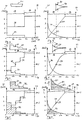
- Fig. 1 shows a sketch of a 3D X-ray device 1 comprising an X-ray detector 2, an X-ray source 3 and a computer 4.
- the X-ray detector 2 is moved clockwise about an object volume 6 to be recorded on a first movement path 5 with a rotation of at least 360°, while the X-ray source 3 is moved in a corresponding manner about an object volume 6 to be recorded on a second movement path 7 with a rotation of at least 360°.
- a plurality of X-ray projection images are recorded from different irradiation directions 8, whereby X-rays 9, which have been produced by means of an X-ray source 3, irradiate the object volume 6 in the corresponding irradiation direction 8 and are captured by the X-ray detector 2.
- a 3D X-ray image 10 of a patient 11 positioned in the object volume 6 is subsequently calculated from the recorded X-ray projection images of the different irradiation directions by means of a reconstruction method and using the computer 4.
- the X-ray detector 2 is arranged asymmetrically relative to a central axis 12 of the 3D X-ray device 1 through a center of rotation 13.
- a first fan beam 14 of the X-rays 9 irradiates the object volume 6.
- the X-ray source 3 is rotated 180° along the movement path 7 in order to reach an opposite position 15.
- the X-ray detector 2 is likewise correspondingly rotated 180° in order to reach an opposite position 16 of the X-ray detector 2.
- the X-ray source emits a second, opposite fan beam 17, which irradiates the object volume 6.
- the first fan beam 14 and the second fan beam 17 irradiate a common overlap region 18. This overlap region 18 is thus measured and irradiated twice, whereas a first remaining region 19 of the first fan beam 14 and a second remaining region 20 of the second fan beam 17 inside the object volume 6 are irradiated and recorded only once.
- first fan beam 14 of one of the irradiation directions 8 there is therefore an opposite second fan beam 17 and an overlap region 18.
- Overlaying all of the overlap regions 18 of the different irradiation directions creates a cylindrical volume of the overlap region 18, which in plan view is shown as a circle around the center of rotation 13.
- Overlaying all of the fan beams 14, 17 of the different irradiation directions 8 likewise results in a cylindrical volume of the object volume 6, which is shown in plan view as a circle.
- 30 to 1,000 X-ray projection images can be recorded per seconds in angular increments between 0.01° and 10°, for example.
- an X-ray filter 21 is disposed in a fixed position relative to the X-ray source 3 and thus relative to the first fan beam 14.
- the X-ray dose inside the overlap region 18 is consequently attenuated as a part of the first fan beam 14, as illustrated by the dotted line 22.
- the X-ray filter 21 is moved to an opposite position 23, so that the overlap region 18 of the opposite second fan beam 17 is attenuated.
- the X-ray filter 21 which may be made of copper, for example, has a cuboid shape, so that the X-ray dose in the overlap region 18 of the first fan beam 14 is attenuated by 50% and the opposite second fan beam 17 inside the overlap region 18 is accordingly also attenuated by 50% done. In total, therefore, a homogeneous X-ray dose of 100% is achieved inside the overlap region 18.
- an aperture 24 is disposed in a fixed position relative to the X-ray source 3, whereby the aperture 24 can be made of tungsten or lead. Upon rotation of the X-ray source 3, the aperture 24 is also moved to an opposite position 25 to produce the second opposite fan beam 17.
- Fig. 2 shows a diagram of a width 30 of the X-ray filter 21 along the central axis 12 of Fig. 1 as a function of a length 31 of the X-ray detector 2 in the direction of movement 5 of Fig. 1 .
- the progression of the width 30 of the X-ray filter 21 as a projection onto the X-ray detector 2, i.e. in dependence of the length of the X-ray detector, is plotted in the first function 32.
- the average energy of the photons of the X-rays of the fan beam 14 is 60 keV.
- the X-ray filter is made of copper.
- the width of the X-ray filter 21 is a constant 0.5 mm inside the overlap region 18, whereby no X-ray filter is disposed inside the first remaining region 19.
- a transmission 33 between 0% and 100% is plotted on a second, y-axis.
- a transmission curve 34 thus shows the dependence of the transmission on the length coordinate 31 of the X-ray detector 2, whereby an attenuation of 50% takes place inside the overlap region or, more specifically, the transmission is 50% and the transmission in the first remaining region 19 is 100%.
- Fig. 3 shows a diagram as in Fig. 2 , wherein the function 32 of the width 30 drops sharply in dependence on the length coordinate 31 of the X-ray detector 2.
- the X-ray filter consequently has a wedge shape 40.
- the transmission curve 34 therefore increases linearly inside the overlap region 18 from 0% to 100% and remains constant within the remaining region 19 at 100%.
- the transmission at a center point 41 of the overlap region 18 is 50%.
- the linearly increasing function 34 is therefore point-symmetrical inside the overlap region 18 relative to the center point of the overlap region 41, so that the addition of the dose of the first fan beam 14 and the dose of the second fan beam 17 of Fig. 1 results in a homogeneous dose distribution of 100%.
- Fig. 4 shows a further embodiment of the X-ray filter, which has a stepped shape 50 with a varying width 30, whereby the associated diagram shows a stepped function 32 of the width 30 in dependence on the length coordinate of the X-ray detector 2.
- the transmission curve 34 consequently shows a stepped increase inside the overlap region 18, which is point-symmetrical relative to the center point 41 of the overlap region 18.
- the transmission in the remaining region 19 is 100%.
- the transmission at the center point 41 of the overlap region is consequently 50%.
- Fig. 5 shows a further embodiment of the X-ray filter having a second wedge shape 60, whereby the width 30 decreases more than for the X-ray filter of Fig. 3 .
- the progression of the function 32 of the width 30 in dependence on the length coordinate 31 thus results in an increasing transmission curve 34, which is point-symmetrical inside the overlap region 18 relative to the center point 41 of the overlap region.
- the transmission at the center point 41 of the overlap region 18 is 50%.
- the transmission inside the remaining region 19 stays at 100%.
- Fig. 6 shows a further embodiment of the X-ray filter 70, comprising a first part 71 and a second part 72, whereby the first part 71 is made of aluminum, for example, and the second part 72 is made of copper, for example.
- the transmission 33 at the center point 41 is 50%.
- Fig. 7 shows a further embodiment of an X-ray filter 80, comprising a first part 81, a second part 82 and a third part 83, whereby the individual parts 81, 82 and 83 are disposed one above the other in irradiation direction 8.
- the parts 81, 82 and 83 can be made of different materials.
- the function 32 of the width 30 in dependence on the length coordinate 31 and the individual materials are therefore selected such that the desired linear progression of the transmission curve 34 inside the overlap region 18 is achieved.
- the transmission 33 at the center point 41 of the overlap region 18 is 50%.
Landscapes
- Health & Medical Sciences (AREA)
- Life Sciences & Earth Sciences (AREA)
- Engineering & Computer Science (AREA)
- Medical Informatics (AREA)
- Physics & Mathematics (AREA)
- High Energy & Nuclear Physics (AREA)
- Heart & Thoracic Surgery (AREA)
- Animal Behavior & Ethology (AREA)
- Optics & Photonics (AREA)
- Pathology (AREA)
- Radiology & Medical Imaging (AREA)
- Biomedical Technology (AREA)
- Biophysics (AREA)
- Molecular Biology (AREA)
- Surgery (AREA)
- Nuclear Medicine, Radiotherapy & Molecular Imaging (AREA)
- General Health & Medical Sciences (AREA)
- Public Health (AREA)
- Veterinary Medicine (AREA)
- Pulmonology (AREA)
- Theoretical Computer Science (AREA)
- Spectroscopy & Molecular Physics (AREA)
- General Engineering & Computer Science (AREA)
- Dentistry (AREA)
- Oral & Maxillofacial Surgery (AREA)
- Apparatus For Radiation Diagnosis (AREA)
Abstract
Description
- The invention relates to a 3D X-ray device comprising an X-ray detector, an X-ray source and a computer, wherein the X-ray detector and the X-ray source are moved about an object volume to be recorded on a movement path with a rotation of at least 185°, wherein a plurality of X-ray projection images are recorded from different irradiation directions, whereby X-rays, which are produced by means of the X-ray source, irradiate the object volume in one of the irradiation directions and are captured by the X-ray detector, wherein a 3D X-ray image of the object volume is calculated from the recorded X-ray projection images by means of a reconstruction method.
- A number of 3D X-ray devices and measurement methods are known from the state of the art.
-
US 8,238,522 B2 discloses a filter changing assembly which can be used in an X-ray device, for example, and comprises shape filters which can be used to produce a radiation beam and which can, for example, be moved back and forth. The filter changing assembly also includes beam hardening filters which can be used to change the energy spectrum of the radiation beam and which can also be moved back and forth, for example. The filter changing assembly includes a control system which can be used to select at least one of the filters and move the selected filter. -
US 2014/0270069 A1 discloses an X-ray device comprising an X-ray source, a collimator for modifying the X-rays, and a motorized system that can be operated to control the collimator. The leaves of the collimator can be configured to modulate a beam quality of the X-rays. The individual leaves of the collimator can be made of different metals, such as aluminum, copper or tin, for example, and have different thicknesses, so that the radiation absorption can be influenced as desired. -
US 2007/0172104 A1 discloses a CT device with an X-ray filter for improving the image quality of a 3D X-ray image. The X-ray filter serves to reduce the dose of the irradiated object. - One disadvantage of the mentioned methods is that, in the case of a rotation of more than 180°, the X-ray device irradiates an overlap region twice, so that objects inside the overlap region are irradiated with a higher dose.
- The object of the present invention is therefore to provide a method and a 3D X-ray device, which records a 3D X-ray image with a homogeneous dose that is distributed across the object volume.
- The invention relates to a 3D X-ray device comprising an X-ray detector, an X-ray source and a computer, wherein the X-ray detector and the X-ray source are moved about an object volume to be recorded on a movement path with a rotation of at least 185°. A plurality of X-ray projection images are recorded from different irradiation directions, whereby X-rays, which are produced by means of the X-ray source, irradiate the object volume in one of the irradiation directions and are captured by the X-ray detector. A 3D X-ray image of the object volume is subsequently calculated from the recorded X-ray projection images by means of a reconstruction method. The X-ray detector is arranged asymmetrically relative to a central axis through a center of rotation of the 3D X-ray device, wherein a first fan beam and an opposite second fan beam rotated 180° form an overlap region. At least one X-ray filter is disposed between the X-ray source and the object volume for attenuating an X-ray dose inside the overlap region, wherein no X-ray filter for attenuating the X-ray dose or a second X-ray filter having a width that differs from a width of the X-ray filter disposed inside the overlap region is provided in the regions of the two fan beams outside the overlap region.
- The 3D X-ray device can be a CT device or a DVT device, for example, wherein the two-dimensional X-ray projection images are produced from the different irradiation directions. During a rotation, the X-ray detector and the X-ray source are rotated at least 185° around the object volume. During rotation, the X-ray detector and the X-ray source describe a, for example, circular or elliptical movement about the object volume, so that the center of rotation of the 3D X-ray device is defined by the circular movement. The central axis of the 3D X-ray device extends from the X-ray source through the center of rotation. The X-ray detector is arranged asymmetrically relative to this central axis, so that, for example, a first distance from the central axis to a first edge of the X-ray detector is smaller than a second distance from the central axis to a second edge of the X-ray detector. The 3D X-ray device can comprise an aperture which is controlled such that the fan beam irradiates the entire sensor surface of the X-ray detector, so that the fan beam, too, is arranged asymmetrically relative to the central axis. For any given first fan beam from a certain irradiation direction there is therefore an opposite second fan beam that is rotated 180°, whereby the first fan beam and the second fan beam are arranged asymmetrically to the central axis. Inside the overlap region, both the first fan beam and the second fan beam irradiate the object volume. The X-ray filter is thus shaped and disposed inside the overlap region such that the attenuation of the X-ray dose inside the overlap region results in a distribution of the dose inside the entire object volume that is as homogeneous as possible. One advantage of the 3D X-ray device is therefore that the arrangement of the asymmetrical X-ray detector and the selection and arrangement of the X-ray filter inside the overlap region make it possible to achieve a dose distribution inside the entire object volume that is as homogeneous as possible. The dose burden for the patient is thus reduced.
- No X-ray filter for attenuating the X-ray dose is therefore disposed in the regions of the object volume outside the overlap region, because said regions are irradiated only once, and not twice as is the case in the overlap region. It is also possible to dispose an additional X-ray filter having a constant or variable width and constant or variable attenuation in these regions outside the overlap region, whereby the X-ray filter is appropriately shaped and disposed inside the overlap region to attenuate the dose inside the overlap region to a dose value within the values outside the overlap region, so that the dose progression inside the object volume is as homogeneous as possible.
- The 3D X-ray device can advantageously be a CT device or a DVT device.
- The 3D X-ray device can therefore be a conventional computed tomography (CT) device or a conventional digital volume tomography (DVT) device, so that the inventive 3D X-ray device can be produced from a conventional CT device or DVT device without much technical effort by equipping said device with the described X-ray filter.
- The shape of the X-ray filter can advantageously be selected such that a transmission curve of the X-ray filter decreases or increases monotonically across the overlap region.
- This shape of the X-ray filter consequently makes the desired dose reduction in the overlap region possible.
- The shape of the X-ray filter can advantageously be selected such that a transmission curve of the X-ray filter is point-symmetrical relative to the center of rotation and has a 50% attenuation of the X-ray dose at a center point of the overlap region.
- In particular in the case of a beam lobe with a spatially constant or approximately constant intensity, this configuration ensures a dose distribution in the object volume that is as homogeneous as possible.
- The transmission curve of the X-ray filter is a function of the transmission or attenuation of the X-ray radiation in dependence on an x-coordinate along the entire length of the X-ray filter. The X-ray filter is therefore shaped and disposed relative to the fan beam such that the transmission curve is point-symmetrical relative to the center of rotation and has a 50% attenuation of the X-ray dose at a center point of the overlap region.
- The center point of the overlap region is the projection of the center of rotation onto the X-ray detector.
- The dose of the first fan beam and the dose of the second opposite fan beam are thus summed, so that the total of the dose results in a homogeneous dose progression inside the overlap region.
- The shape of the X-ray filter can advantageously be selected such that a transmission curve of the X-ray filter increases monotonically inside the overlap region, for example from 0% to 100%.
- The shape of the X-ray filter can advantageously be a cuboid shape, a wedge shape, a stepped shape or a shape adapted to a weighting curve of a 3D reconstruction method.
- The X-ray filter can thus have a cuboid shape, for example, whereby the transmission curve has a constant attenuation of the X-ray dose of 50% along the entire length of the overlap region. In the case of a wedge shape of the X-ray filter, the width of the X-ray filter along the length is selected such that the transmission curve, for example, creates a straight line from 0% to 100% of the transmission along the length of the X-ray filter. In the case of a stepped shape of the X-ray filter, the width of the X-ray filter along the entire length is selected such that the transmission curve has a stepped progression. The transmission curve can have uniform stepped increases, for example, that are arranged point-symmetrically to the center of the overlap region. The shape of the X-ray filter can be adapted to the weighting curve of a 3D reconstruction method, whereby the width of the X-ray filter along the length is selected such that a point-symmetrical transmission curve having a selected progression is produced.
- The X-ray detector and the X-ray source can advantageously be moved about the object volume to be recorded on a movement path with a rotation of at least 360°.
- As a result of the rotation of at least 360°, the entire object volume to be recorded is measured twice, so that for any given first radiation beam there is a second opposite radiation beam, and a homogeneous dose progression inside the overlap region is created.
- To attenuate the X-ray dose inside the overlap region, a plurality of X-ray filters of different widths and shapes can advantageously be disposed between the X-ray source and the object volume.
- The individual X-ray filters can be two wedge-shaped X-ray filters and a cuboid X-ray filter, for example, that are disposed inside the overlap region one above the other in the direction of the X-rays. The X-ray filters disposed one above the other thus also produce the desired transmission curve.
- At the transition between the overlap region and the remaining region of the first fan beam and the second opposite fan beam, it is important that no intermittency of the dose progression develops.
- The X-ray filter can advantageously be constructed of a plurality of layers, wherein the individual layers consist of materials having different X-ray absorption properties, whereby the individual layers of the X-ray filter are constructed such that a desired transmission curve is produced.
- The X-ray filter is thus constructed from a plurality of layers of different materials, such as copper or aluminum, so that the desired, possibly point-symmetrical, transmission curve is produced. The individual layers of the X-ray filter can be arranged parallel to the X-rays of the X-ray fan beam, so that the different X-ray absorption properties of the materials and the width of the individual layers produce the desired transmission curve.
- The 3D X-ray device can advantageously comprise an aperture between the X-ray source and the object volume in order to form the fan beam, whereby the X-ray filter is disposed between the aperture and the X-ray source or between the aperture and the object volume.
- The fan beam is therefore collimated by the aperture, whereby the X-rays hitting the aperture are absorbed. The X-ray filter can thus be disposed in front of the aperture or behind the aperture.
- The computer can advantageously be configured such that the attenuation of the X-ray dose by the at least one X-ray filter is taken into account in the calculation of the 3D X-ray image by means of the reconstruction method.
- The attenuation or the transmission curve of the X-ray filter is thus taken into account in the calculation of the 3D X-ray image, so that potential distortions and imaging errors are prevented. The calculation by means of the reconstruction method therefore assumes the correct, X-ray filter-attenuated dose for each voxel of the object volume.
- The X-ray filter can advantageously be made of copper or aluminum.
- The materials copper and aluminum are particularly advantageous for the targeted attenuation of X-rays.
- The X-ray filter can advantageously be moved automatically into a desired position relative to the radiation beam by means of a control unit and a drive unit.
- The drive unit can comprise an electric motor, for example, so that the X-ray filter is positioned as desired relative to the radiation beam under the control of the control unit. This may be necessary, for example, if the size of the fan beam is changed by an adjustment of the aperture. The X-ray filter is therefore positioned relative to the radiation beam in the desired manner, for example such that the transmission curve is point-symmetrical and has a 50% attenuation of the X-ray dose at the center point of the overlap region.
- The invention further relates to a method for producing a 3D X-ray image by means of the 3D X-ray device according to the inventive method discussed above, whereby the attenuation of the X-ray dose by the X-ray filter is taken into account in the calculation of the 3D X-ray image from the individual X-ray projection images by means of the reconstruction method.
- One advantage of the inventive method is therefore that, using the above-described 3D X-ray device with the described X-ray filter, a 3D X-ray image is recorded with a reduced dose burden. The calculation by means of the reconstruction method therefore assumes the X-ray filter-attenuated dose for each voxel of the object volume.
- The invention will be explained with reference to the drawings. The drawings show:
- Fig. 1
- a sketch of a 3D X-ray device,
- Fig. 2
- a rectangular embodiment of the X-ray filter,
- Fig. 3
- a wedge-shaped embodiment of the X-ray filter,
- Fig. 4
- a stepped embodiment of the X-ray filter,
- Fig. 5
- a wedge-shaped embodiment of the X-ray filter,
- Fig. 6
- a stepped embodiment of the X-ray filter consisting of two pieces,
- Fig. 7
- a wedge-shaped embodiment of the X-ray filter consisting of three layers.
-
Fig. 1 shows a sketch of a3D X-ray device 1 comprising anX-ray detector 2, anX-ray source 3 and acomputer 4. TheX-ray detector 2 is moved clockwise about an object volume 6 to be recorded on afirst movement path 5 with a rotation of at least 360°, while theX-ray source 3 is moved in a corresponding manner about an object volume 6 to be recorded on a second movement path 7 with a rotation of at least 360°. During the rotation, a plurality of X-ray projection images are recorded fromdifferent irradiation directions 8, whereby X-rays 9, which have been produced by means of anX-ray source 3, irradiate the object volume 6 in thecorresponding irradiation direction 8 and are captured by theX-ray detector 2. A3D X-ray image 10 of a patient 11 positioned in the object volume 6 is subsequently calculated from the recorded X-ray projection images of the different irradiation directions by means of a reconstruction method and using thecomputer 4. TheX-ray detector 2 is arranged asymmetrically relative to acentral axis 12 of the3D X-ray device 1 through a center ofrotation 13. Afirst fan beam 14 of the X-rays 9 irradiates the object volume 6. TheX-ray source 3 is rotated 180° along the movement path 7 in order to reach anopposite position 15. TheX-ray detector 2 is likewise correspondingly rotated 180° in order to reach anopposite position 16 of theX-ray detector 2. In theopposite position 15, the X-ray source emits a second,opposite fan beam 17, which irradiates the object volume 6. Thefirst fan beam 14 and thesecond fan beam 17 irradiate acommon overlap region 18. Thisoverlap region 18 is thus measured and irradiated twice, whereas a first remainingregion 19 of thefirst fan beam 14 and a second remainingregion 20 of thesecond fan beam 17 inside the object volume 6 are irradiated and recorded only once. For everyfirst fan beam 14 of one of theirradiation directions 8, there is therefore an oppositesecond fan beam 17 and anoverlap region 18. Overlaying all of theoverlap regions 18 of the different irradiation directions creates a cylindrical volume of theoverlap region 18, which in plan view is shown as a circle around the center ofrotation 13. Overlaying all of the fan beams 14, 17 of thedifferent irradiation directions 8 likewise results in a cylindrical volume of the object volume 6, which is shown in plan view as a circle. During the movement of theX-ray detector 2 about theobject volume 6, 30 to 1,000 X-ray projection images can be recorded per seconds in angular increments between 0.01° and 10°, for example. - To attenuate the X-ray dose inside the
overlap region 18, anX-ray filter 21 is disposed in a fixed position relative to theX-ray source 3 and thus relative to thefirst fan beam 14. The X-ray dose inside theoverlap region 18 is consequently attenuated as a part of thefirst fan beam 14, as illustrated by the dotted line 22. As a result of the rotation of theX-ray source 3 and theopposite position 15, theX-ray filter 21 is moved to anopposite position 23, so that theoverlap region 18 of the oppositesecond fan beam 17 is attenuated. In the present case, theX-ray filter 21, which may be made of copper, for example, has a cuboid shape, so that the X-ray dose in theoverlap region 18 of thefirst fan beam 14 is attenuated by 50% and the oppositesecond fan beam 17 inside theoverlap region 18 is accordingly also attenuated by 50% done. In total, therefore, a homogeneous X-ray dose of 100% is achieved inside theoverlap region 18. To produce thefan beam 14, anaperture 24 is disposed in a fixed position relative to theX-ray source 3, whereby theaperture 24 can be made of tungsten or lead. Upon rotation of theX-ray source 3, theaperture 24 is also moved to anopposite position 25 to produce the secondopposite fan beam 17. -
Fig. 2 shows a diagram of awidth 30 of theX-ray filter 21 along thecentral axis 12 ofFig. 1 as a function of alength 31 of theX-ray detector 2 in the direction ofmovement 5 ofFig. 1 . The progression of thewidth 30 of theX-ray filter 21 as a projection onto theX-ray detector 2, i.e. in dependence of the length of the X-ray detector, is plotted in thefirst function 32. In the present case, the average energy of the photons of the X-rays of thefan beam 14 is 60 keV. The X-ray filter is made of copper. It can therefore be seen from thefirst function 32 that the width of theX-ray filter 21 is a constant 0.5 mm inside theoverlap region 18, whereby no X-ray filter is disposed inside the first remainingregion 19. Atransmission 33 between 0% and 100% is plotted on a second, y-axis. Atransmission curve 34 thus shows the dependence of the transmission on the length coordinate 31 of theX-ray detector 2, whereby an attenuation of 50% takes place inside the overlap region or, more specifically, the transmission is 50% and the transmission in the first remainingregion 19 is 100%. -
Fig. 3 shows a diagram as inFig. 2 , wherein thefunction 32 of thewidth 30 drops sharply in dependence on the length coordinate 31 of theX-ray detector 2. The X-ray filter consequently has awedge shape 40. Thetransmission curve 34 therefore increases linearly inside theoverlap region 18 from 0% to 100% and remains constant within the remainingregion 19 at 100%. The transmission at acenter point 41 of theoverlap region 18 is 50%. The linearly increasingfunction 34 is therefore point-symmetrical inside theoverlap region 18 relative to the center point of theoverlap region 41, so that the addition of the dose of thefirst fan beam 14 and the dose of thesecond fan beam 17 ofFig. 1 results in a homogeneous dose distribution of 100%. -
Fig. 4 shows a further embodiment of the X-ray filter, which has a steppedshape 50 with a varyingwidth 30, whereby the associated diagram shows a steppedfunction 32 of thewidth 30 in dependence on the length coordinate of theX-ray detector 2. Thetransmission curve 34 consequently shows a stepped increase inside theoverlap region 18, which is point-symmetrical relative to thecenter point 41 of theoverlap region 18. The transmission in the remainingregion 19 is 100%. The transmission at thecenter point 41 of the overlap region is consequently 50%. -
Fig. 5 shows a further embodiment of the X-ray filter having asecond wedge shape 60, whereby thewidth 30 decreases more than for the X-ray filter ofFig. 3 . The progression of thefunction 32 of thewidth 30 in dependence on the length coordinate 31 thus results in an increasingtransmission curve 34, which is point-symmetrical inside theoverlap region 18 relative to thecenter point 41 of the overlap region. The transmission at thecenter point 41 of theoverlap region 18 is 50%. The transmission inside the remainingregion 19 stays at 100%. -
Fig. 6 shows a further embodiment of theX-ray filter 70, comprising afirst part 71 and asecond part 72, whereby thefirst part 71 is made of aluminum, for example, and thesecond part 72 is made of copper, for example. The different X-ray absorption properties of the twoparts function 32 of thewidth 30 in dependence of the adjacent coordinate 31, result in the desired steppedtransmission curve 34, which extends point-symmetrically inside theoverlap region 18 relative to thecenter point 41 of theoverlap region 18. Thetransmission 33 at thecenter point 41 is 50%. -
Fig. 7 shows a further embodiment of anX-ray filter 80, comprising afirst part 81, asecond part 82 and athird part 83, whereby theindividual parts irradiation direction 8. Theparts function 32 of thewidth 30 in dependence on the length coordinate 31 and the individual materials are therefore selected such that the desired linear progression of thetransmission curve 34 inside theoverlap region 18 is achieved. Thetransmission 33 at thecenter point 41 of theoverlap region 18 is 50%. -
- 1
- 3D X-ray device
- 2
- X-ray detector
- 3
- X-ray source
- 4
- Computer
- 5
- Movement path
- 6
- Object volume
- 7
- Second movement path
- 8
- Irradiation direction
- 9
- X-rays
- 10
- 3D X-ray image
- 11
- Patient
- 12
- Central axis
- 13
- Center of rotation
- 14
- First fan beam
- 15
- Opposite position of the
X-ray source 3 - 16
- Opposite position of the
X-ray detector 2 - 17
- Second, opposite fan beam
- 18
- Overlap region
- 19
- First remaining region
- 20
- Second remaining region
- 21
- X-ray filter
- 22
- Dotted line
- 23
- Opposite position of the X-ray filter
- 24
- Aperture
- 25
- Opposite position of the X-ray source
- 30
- Width of the X-ray filter
- 31
- Length of the X-ray detector
- 32
- First function
- 33
- Transmission
- 34
- Transmission curve
- 40
- Wedge-shaped X-ray filter
- 41
- Center point of the overlap region
- 50
- Stepped X-ray filter
- 60
- Second wedge-shaped X-ray filter
- 70
- Further X-ray filter, two-part
- 71
- First part of the X-ray filter
- 72
- Second part of the X-ray filter
- 80
- Further X-ray filter, three-part
- 81
- First part of the X-ray filter
- 82
- Second part of the X-ray filter
- 83
- Third part of the X-ray filter
Claims (13)
- 3D X-ray device (1) comprising an X-ray detector (2), an X-ray source (3) and a computer (4), wherein the X-ray detector (2) and the X-ray source (3) are moved about an object volume (6) to be recorded in a craniomaxillofacial region on movement paths (5, 7) with a rotation of at least 185°, wherein a plurality of X-ray projection images are recorded from different irradiation directions (8), whereby X-rays (9), which are produced by means of the X-ray source (3), irradiate the object volume (6) in one of the irradiation directions (8) and are captured by the X-ray detector (2), wherein a 3D X-ray image (10) of the object volume (6) is calculated from the recorded X-ray projection images by means of a reconstruction method, characterized in that the X-ray detector (2) is arranged asymmetrically relative to a central axis (12) through a center of rotation (13) of the 3D X-ray device (1), wherein a first fan beam (14) and an opposite second fan beam (17) rotated 180° form an overlap region (18), wherein at least one X-ray filter (21) is disposed between the X-ray source (3) and the object volume (6) for attenuating an X-ray dose inside the overlap region (18), wherein no X-ray filter for attenuating the X-ray dose or a second X-ray filter having a width that differs from a width (30) of the X-ray filter (21) disposed inside the overlap region (18) is provided in the regions (19, 20) of the two fan beams (14, 17) outside the overlap region (18).
- 3D X-ray device (1) according to Claim 1, characterized in that the 3D X-ray device (1) is a CT device or a DVT device.
- 3D X-ray device (1) according to Claim 1 or 2, characterized in that the shape of the X-ray filter (21) is selected such that a transmission curve (34) of the X-ray filter (21) decreases or increases monotonically across the overlap region.
- 3D X-ray device (1) according to any one of Claims 1-3, characterized in that the shape of the X-ray filter (21) is selected such that a transmission curve (34) of the X-ray filter (21) relative to the center of rotation (13) is point-symmetrical and exhibits an attenuation of the X-ray dose of 10-75% in a center point (41) of the overlap region (18).
- 3D X-ray device (1) according to any one of Claims 1-4, characterized in that the shape of the X-ray filter (21) is a cuboid shape, a wedge shape (40, 60, 80), a stepped shape (50, 70) or a shape adapted to a weighting curve.
- 3D X-ray device (1) according to any one of Claims 1-5, characterized in that the X-ray detector (2) and the X-ray source (3) are moved about an object volume (6) to be recorded on movement paths (5, 7) with a rotation of at least 360°.
- 3D X-ray device (1) according to any one of Claims 1-6, characterized in that a plurality of X-ray filters (71, 72) of different widths and shapes are disposed between the X-ray source (3) and the object volume (6) for attenuating the X-ray dose inside the overlap region (18).
- 3D X-ray device (1) according to any one of Claims 1-7, characterized in that the X-ray filter (80) is constructed from a plurality of layers (81, 82, 83), wherein the individual layers (81, 82, 83) consist of materials having different X-ray absorption properties, wherein the individual layers (81, 82, 83) of the X-ray filter (80) are constructed such that a desired transmission curve (34) is produced.
- 3D X-ray device (1) according to any one of Claims 1-8, characterized in that the 3D X-ray device (1) comprises an aperture (24) between the X-ray source (3) and the object volume (6) in order to form the fan beam (14, 17), wherein the X-ray filter (21) is disposed between the aperture and the X-ray source (3) or between the aperture (24) and the object volume (6).
- 3D X-ray device (1) according to any one of Claims 1-9, characterized in that the computer (4) is configured such that the attenuation of the X-ray dose by the at least one X-ray filter (21) is taken into account in the calculation of the 3D X-ray image (10) by means of the reconstruction method.
- 3D X-ray device (1) according to any one of Claims 1-10, characterized in that the X-ray filter (21) is made of copper or aluminum.
- 3D X-ray device (1) according to any one of Claims 1-11, characterized in that the X-ray filter (21) is automatically moved into a desired position relative to the radiation beam (14) by means of a control unit and a drive unit.
- Method for producing a 3D X-ray image (10) by means of the 3D X-ray device (1) according to any one of Claims 1-12, characterized in that the attenuation of the X-ray dose by the X-ray filter (21) is taken into account in the calculation of the 3D X-ray image (10) from the individual X-ray projection images by means of the reconstruction method.
Priority Applications (7)
| Application Number | Priority Date | Filing Date | Title |
|---|---|---|---|
| EP19212720.7A EP3827750B1 (en) | 2019-11-29 | 2019-11-29 | 3d x-ray device and a method for producing a 3d x-ray image |
| FIEP19212720.7T FI3827750T3 (en) | 2019-11-29 | 2019-11-29 | 3d x-ray device and a method for producing a 3d x-ray image |
| JP2022528091A JP7739281B2 (en) | 2019-11-29 | 2020-11-27 | 3D X-ray device and method for producing 3D X-ray images |
| CN202080082274.3A CN114727793B (en) | 2019-11-29 | 2020-11-27 | 3D X-ray device and method for generating 3D X-ray images |
| US17/780,107 US12263023B2 (en) | 2019-11-29 | 2020-11-27 | 3D X-ray device and method for producing a 3D X-ray image |
| KR1020227017095A KR20220110485A (en) | 2019-11-29 | 2020-11-27 | 3D X-Ray Devices and Methods for Creating 3D X-Ray Images |
| PCT/EP2020/083700 WO2021105402A1 (en) | 2019-11-29 | 2020-11-27 | 3d x-ray device and method for producing a 3d x-ray image |
Applications Claiming Priority (1)
| Application Number | Priority Date | Filing Date | Title |
|---|---|---|---|
| EP19212720.7A EP3827750B1 (en) | 2019-11-29 | 2019-11-29 | 3d x-ray device and a method for producing a 3d x-ray image |
Publications (2)
| Publication Number | Publication Date |
|---|---|
| EP3827750A1 true EP3827750A1 (en) | 2021-06-02 |
| EP3827750B1 EP3827750B1 (en) | 2024-02-28 |
Family
ID=68762494
Family Applications (1)
| Application Number | Title | Priority Date | Filing Date |
|---|---|---|---|
| EP19212720.7A Active EP3827750B1 (en) | 2019-11-29 | 2019-11-29 | 3d x-ray device and a method for producing a 3d x-ray image |
Country Status (7)
| Country | Link |
|---|---|
| US (1) | US12263023B2 (en) |
| EP (1) | EP3827750B1 (en) |
| JP (1) | JP7739281B2 (en) |
| KR (1) | KR20220110485A (en) |
| CN (1) | CN114727793B (en) |
| FI (1) | FI3827750T3 (en) |
| WO (1) | WO2021105402A1 (en) |
Cited By (1)
| Publication number | Priority date | Publication date | Assignee | Title |
|---|---|---|---|---|
| US12263023B2 (en) | 2019-11-29 | 2025-04-01 | Dentsply Sirona Inc. | 3D X-ray device and method for producing a 3D X-ray image |
Families Citing this family (1)
| Publication number | Priority date | Publication date | Assignee | Title |
|---|---|---|---|---|
| CN119423788A (en) * | 2023-08-01 | 2025-02-14 | 西门子(深圳)磁共振有限公司 | Parameter optimization method, device, medical equipment, medium and product |
Citations (9)
| Publication number | Priority date | Publication date | Assignee | Title |
|---|---|---|---|---|
| US20030147502A1 (en) * | 2001-12-11 | 2003-08-07 | Bjorn Heismann | X-ray imaging apparatus with tube side filter for dividing the x-ray beam into multiple beams of differing intensities |
| US20040258195A1 (en) * | 2003-06-17 | 2004-12-23 | Yukihiro Hara | Diagnostic X-ray system and CT image production method |
| US20050089146A1 (en) * | 2003-10-27 | 2005-04-28 | Toth Thomas L. | Method and apparatus of radiographic imaging with an energy beam tailored for a subject to be scanned |
| US20070172104A1 (en) | 2006-01-19 | 2007-07-26 | Akihiko Nishide | Image display apparatus and x-ray ct apparatus |
| EP2234541A1 (en) * | 2007-12-20 | 2010-10-06 | Koninklijke Philips Electronics N.V. | Stereo tube attenuation filter |
| US20100308229A1 (en) * | 2007-11-15 | 2010-12-09 | Koninklijke Philips Electronics N.V. | Movable wedge for improved image quality in 3d x-ray imaging |
| US20110261923A1 (en) * | 2009-01-12 | 2011-10-27 | Koninklijke Philips Electronics N.V. | Method and apparatus to filter x-ray beams generated using a ct apparatus with displaced geometry |
| US8238522B2 (en) | 2010-04-12 | 2012-08-07 | Varian Medical Systems International Ag | Filter changing assembly for filtering a radiation beam |
| US20140270069A1 (en) | 2013-03-14 | 2014-09-18 | Varian Medical Systems, Inc. | Real-time moving collimators made with x-ray filtering material |
Family Cites Families (8)
| Publication number | Priority date | Publication date | Assignee | Title |
|---|---|---|---|---|
| JPS5949009B2 (en) * | 1977-09-12 | 1984-11-30 | 株式会社東芝 | Radiation tomography device |
| JP2009089810A (en) | 2007-10-05 | 2009-04-30 | Ge Medical Systems Global Technology Co Llc | X-ray ct system |
| RU2499559C2 (en) * | 2007-12-21 | 2013-11-27 | Конинклейке Филипс Электроникс, Н.В. | Collimator for through scanning |
| EP2130494A1 (en) * | 2008-06-06 | 2009-12-09 | Helmholtz Zentrum München Deutsches Forschungszentrum für Gesundheit und Umwelt (GmbH) | Scanner device and method for computed tomography imaging |
| CN103349556B (en) | 2009-01-21 | 2015-09-23 | 皇家飞利浦电子股份有限公司 | For Large visual angle imaging and the detection of motion artifacts and the method and apparatus of compensation |
| JP6165826B2 (en) | 2014-11-28 | 2017-07-19 | 株式会社モリタ製作所 | X-ray imaging apparatus, image processing apparatus, and X-ray imaging method |
| DE102015225130A1 (en) | 2015-12-14 | 2017-06-14 | Sirona Dental Systems Gmbh | Method for calibrating an X-ray image |
| FI3827750T3 (en) | 2019-11-29 | 2024-05-23 | Sirona Dental Systems Gmbh | 3d x-ray device and a method for producing a 3d x-ray image |
-
2019
- 2019-11-29 FI FIEP19212720.7T patent/FI3827750T3/en active
- 2019-11-29 EP EP19212720.7A patent/EP3827750B1/en active Active
-
2020
- 2020-11-27 US US17/780,107 patent/US12263023B2/en active Active
- 2020-11-27 WO PCT/EP2020/083700 patent/WO2021105402A1/en not_active Ceased
- 2020-11-27 JP JP2022528091A patent/JP7739281B2/en active Active
- 2020-11-27 CN CN202080082274.3A patent/CN114727793B/en active Active
- 2020-11-27 KR KR1020227017095A patent/KR20220110485A/en not_active Ceased
Patent Citations (9)
| Publication number | Priority date | Publication date | Assignee | Title |
|---|---|---|---|---|
| US20030147502A1 (en) * | 2001-12-11 | 2003-08-07 | Bjorn Heismann | X-ray imaging apparatus with tube side filter for dividing the x-ray beam into multiple beams of differing intensities |
| US20040258195A1 (en) * | 2003-06-17 | 2004-12-23 | Yukihiro Hara | Diagnostic X-ray system and CT image production method |
| US20050089146A1 (en) * | 2003-10-27 | 2005-04-28 | Toth Thomas L. | Method and apparatus of radiographic imaging with an energy beam tailored for a subject to be scanned |
| US20070172104A1 (en) | 2006-01-19 | 2007-07-26 | Akihiko Nishide | Image display apparatus and x-ray ct apparatus |
| US20100308229A1 (en) * | 2007-11-15 | 2010-12-09 | Koninklijke Philips Electronics N.V. | Movable wedge for improved image quality in 3d x-ray imaging |
| EP2234541A1 (en) * | 2007-12-20 | 2010-10-06 | Koninklijke Philips Electronics N.V. | Stereo tube attenuation filter |
| US20110261923A1 (en) * | 2009-01-12 | 2011-10-27 | Koninklijke Philips Electronics N.V. | Method and apparatus to filter x-ray beams generated using a ct apparatus with displaced geometry |
| US8238522B2 (en) | 2010-04-12 | 2012-08-07 | Varian Medical Systems International Ag | Filter changing assembly for filtering a radiation beam |
| US20140270069A1 (en) | 2013-03-14 | 2014-09-18 | Varian Medical Systems, Inc. | Real-time moving collimators made with x-ray filtering material |
Cited By (1)
| Publication number | Priority date | Publication date | Assignee | Title |
|---|---|---|---|---|
| US12263023B2 (en) | 2019-11-29 | 2025-04-01 | Dentsply Sirona Inc. | 3D X-ray device and method for producing a 3D X-ray image |
Also Published As
| Publication number | Publication date |
|---|---|
| JP7739281B2 (en) | 2025-09-16 |
| KR20220110485A (en) | 2022-08-08 |
| WO2021105402A1 (en) | 2021-06-03 |
| EP3827750B1 (en) | 2024-02-28 |
| JP2023503408A (en) | 2023-01-30 |
| CN114727793B (en) | 2024-10-15 |
| CN114727793A (en) | 2022-07-08 |
| US20230009790A1 (en) | 2023-01-12 |
| US12263023B2 (en) | 2025-04-01 |
| FI3827750T3 (en) | 2024-05-23 |
Similar Documents
| Publication | Publication Date | Title |
|---|---|---|
| JP7564098B2 (en) | Helical fan-beam computed tomography integrated within an image-guided radiotherapy device | |
| US11673004B2 (en) | X-ray imaging system with a combined filter and collimator positioning mechanism | |
| US7324623B2 (en) | Computed tomography scanner with large gantry bore | |
| US8031834B2 (en) | Tomosynthesis apparatus and method to operate a tomosynthesis apparatus | |
| US8853636B2 (en) | Linear accelerators | |
| US8218721B2 (en) | X-ray beam modifying diaphragm and diaphragm device | |
| US20140112431A1 (en) | X-ray beam transmission profile shaper | |
| KR101609932B1 (en) | Curved movable beam stop array and CBCT comprising thereof | |
| US8964942B2 (en) | Imaging system using multisource collimation and a method assembly and system for providing multisource collimation | |
| US12263023B2 (en) | 3D X-ray device and method for producing a 3D X-ray image | |
| EP4224215B1 (en) | Method for saturation correction and dynamic gain configuration | |
| WO2010079393A1 (en) | Method and apparatus to filter x-ray beams generated using a ct apparatus with displaced geometry | |
| JP6467420B2 (en) | Adjustable bow tie filter and method for adjusting using bow tie filter to achieve optimum SNR in helical computed tomography |
Legal Events
| Date | Code | Title | Description |
|---|---|---|---|
| PUAI | Public reference made under article 153(3) epc to a published international application that has entered the european phase |
Free format text: ORIGINAL CODE: 0009012 |
|
| STAA | Information on the status of an ep patent application or granted ep patent |
Free format text: STATUS: THE APPLICATION HAS BEEN PUBLISHED |
|
| AK | Designated contracting states |
Kind code of ref document: A1 Designated state(s): AL AT BE BG CH CY CZ DE DK EE ES FI FR GB GR HR HU IE IS IT LI LT LU LV MC MK MT NL NO PL PT RO RS SE SI SK SM TR |
|
| STAA | Information on the status of an ep patent application or granted ep patent |
Free format text: STATUS: REQUEST FOR EXAMINATION WAS MADE |
|
| 17P | Request for examination filed |
Effective date: 20211202 |
|
| RBV | Designated contracting states (corrected) |
Designated state(s): AL AT BE BG CH CY CZ DE DK EE ES FI FR GB GR HR HU IE IS IT LI LT LU LV MC MK MT NL NO PL PT RO RS SE SI SK SM TR |
|
| P01 | Opt-out of the competence of the unified patent court (upc) registered |
Effective date: 20230524 |
|
| GRAP | Despatch of communication of intention to grant a patent |
Free format text: ORIGINAL CODE: EPIDOSNIGR1 |
|
| STAA | Information on the status of an ep patent application or granted ep patent |
Free format text: STATUS: GRANT OF PATENT IS INTENDED |
|
| RIC1 | Information provided on ipc code assigned before grant |
Ipc: A61B 6/10 20060101ALN20230921BHEP Ipc: A61B 6/02 20060101ALN20230921BHEP Ipc: A61B 6/03 20060101ALN20230921BHEP Ipc: G06T 11/00 20060101ALI20230921BHEP Ipc: G21K 1/02 20060101ALI20230921BHEP Ipc: A61B 6/00 20060101ALI20230921BHEP Ipc: A61B 6/06 20060101AFI20230921BHEP |
|
| INTG | Intention to grant announced |
Effective date: 20231012 |
|
| RIC1 | Information provided on ipc code assigned before grant |
Ipc: A61B 6/10 20060101ALN20230929BHEP Ipc: A61B 6/02 20060101ALN20230929BHEP Ipc: A61B 6/03 20060101ALN20230929BHEP Ipc: G06T 11/00 20060101ALI20230929BHEP Ipc: G21K 1/02 20060101ALI20230929BHEP Ipc: A61B 6/00 20060101ALI20230929BHEP Ipc: A61B 6/06 20060101AFI20230929BHEP |
|
| GRAS | Grant fee paid |
Free format text: ORIGINAL CODE: EPIDOSNIGR3 |
|
| GRAA | (expected) grant |
Free format text: ORIGINAL CODE: 0009210 |
|
| STAA | Information on the status of an ep patent application or granted ep patent |
Free format text: STATUS: THE PATENT HAS BEEN GRANTED |
|
| AK | Designated contracting states |
Kind code of ref document: B1 Designated state(s): AL AT BE BG CH CY CZ DE DK EE ES FI FR GB GR HR HU IE IS IT LI LT LU LV MC MK MT NL NO PL PT RO RS SE SI SK SM TR |
|
| REG | Reference to a national code |
Ref country code: GB Ref legal event code: FG4D |
|
| REG | Reference to a national code |
Ref country code: CH Ref legal event code: EP |
|
| REG | Reference to a national code |
Ref country code: DE Ref legal event code: R096 Ref document number: 602019047245 Country of ref document: DE |
|
| REG | Reference to a national code |
Ref country code: IE Ref legal event code: FG4D |
|
| REG | Reference to a national code |
Ref country code: FI Ref legal event code: FGE |
|
| REG | Reference to a national code |
Ref country code: LT Ref legal event code: MG9D |
|
| PG25 | Lapsed in a contracting state [announced via postgrant information from national office to epo] |
Ref country code: IS Free format text: LAPSE BECAUSE OF FAILURE TO SUBMIT A TRANSLATION OF THE DESCRIPTION OR TO PAY THE FEE WITHIN THE PRESCRIBED TIME-LIMIT Effective date: 20240628 |
|
| REG | Reference to a national code |
Ref country code: NL Ref legal event code: MP Effective date: 20240228 |
|
| PG25 | Lapsed in a contracting state [announced via postgrant information from national office to epo] |
Ref country code: LT Free format text: LAPSE BECAUSE OF FAILURE TO SUBMIT A TRANSLATION OF THE DESCRIPTION OR TO PAY THE FEE WITHIN THE PRESCRIBED TIME-LIMIT Effective date: 20240228 |
|
| PG25 | Lapsed in a contracting state [announced via postgrant information from national office to epo] |
Ref country code: GR Free format text: LAPSE BECAUSE OF FAILURE TO SUBMIT A TRANSLATION OF THE DESCRIPTION OR TO PAY THE FEE WITHIN THE PRESCRIBED TIME-LIMIT Effective date: 20240529 |
|
| PG25 | Lapsed in a contracting state [announced via postgrant information from national office to epo] |
Ref country code: NL Free format text: LAPSE BECAUSE OF FAILURE TO SUBMIT A TRANSLATION OF THE DESCRIPTION OR TO PAY THE FEE WITHIN THE PRESCRIBED TIME-LIMIT Effective date: 20240228 Ref country code: HR Free format text: LAPSE BECAUSE OF FAILURE TO SUBMIT A TRANSLATION OF THE DESCRIPTION OR TO PAY THE FEE WITHIN THE PRESCRIBED TIME-LIMIT Effective date: 20240228 Ref country code: RS Free format text: LAPSE BECAUSE OF FAILURE TO SUBMIT A TRANSLATION OF THE DESCRIPTION OR TO PAY THE FEE WITHIN THE PRESCRIBED TIME-LIMIT Effective date: 20240528 |
|
| PG25 | Lapsed in a contracting state [announced via postgrant information from national office to epo] |
Ref country code: ES Free format text: LAPSE BECAUSE OF FAILURE TO SUBMIT A TRANSLATION OF THE DESCRIPTION OR TO PAY THE FEE WITHIN THE PRESCRIBED TIME-LIMIT Effective date: 20240228 |
|
| PG25 | Lapsed in a contracting state [announced via postgrant information from national office to epo] |
Ref country code: RS Free format text: LAPSE BECAUSE OF FAILURE TO SUBMIT A TRANSLATION OF THE DESCRIPTION OR TO PAY THE FEE WITHIN THE PRESCRIBED TIME-LIMIT Effective date: 20240528 Ref country code: NO Free format text: LAPSE BECAUSE OF FAILURE TO SUBMIT A TRANSLATION OF THE DESCRIPTION OR TO PAY THE FEE WITHIN THE PRESCRIBED TIME-LIMIT Effective date: 20240528 Ref country code: NL Free format text: LAPSE BECAUSE OF FAILURE TO SUBMIT A TRANSLATION OF THE DESCRIPTION OR TO PAY THE FEE WITHIN THE PRESCRIBED TIME-LIMIT Effective date: 20240228 Ref country code: LT Free format text: LAPSE BECAUSE OF FAILURE TO SUBMIT A TRANSLATION OF THE DESCRIPTION OR TO PAY THE FEE WITHIN THE PRESCRIBED TIME-LIMIT Effective date: 20240228 Ref country code: IS Free format text: LAPSE BECAUSE OF FAILURE TO SUBMIT A TRANSLATION OF THE DESCRIPTION OR TO PAY THE FEE WITHIN THE PRESCRIBED TIME-LIMIT Effective date: 20240628 Ref country code: HR Free format text: LAPSE BECAUSE OF FAILURE TO SUBMIT A TRANSLATION OF THE DESCRIPTION OR TO PAY THE FEE WITHIN THE PRESCRIBED TIME-LIMIT Effective date: 20240228 Ref country code: GR Free format text: LAPSE BECAUSE OF FAILURE TO SUBMIT A TRANSLATION OF THE DESCRIPTION OR TO PAY THE FEE WITHIN THE PRESCRIBED TIME-LIMIT Effective date: 20240529 Ref country code: ES Free format text: LAPSE BECAUSE OF FAILURE TO SUBMIT A TRANSLATION OF THE DESCRIPTION OR TO PAY THE FEE WITHIN THE PRESCRIBED TIME-LIMIT Effective date: 20240228 Ref country code: BG Free format text: LAPSE BECAUSE OF FAILURE TO SUBMIT A TRANSLATION OF THE DESCRIPTION OR TO PAY THE FEE WITHIN THE PRESCRIBED TIME-LIMIT Effective date: 20240228 |
|
| PG25 | Lapsed in a contracting state [announced via postgrant information from national office to epo] |
Ref country code: PL Free format text: LAPSE BECAUSE OF FAILURE TO SUBMIT A TRANSLATION OF THE DESCRIPTION OR TO PAY THE FEE WITHIN THE PRESCRIBED TIME-LIMIT Effective date: 20240228 Ref country code: PT Free format text: LAPSE BECAUSE OF FAILURE TO SUBMIT A TRANSLATION OF THE DESCRIPTION OR TO PAY THE FEE WITHIN THE PRESCRIBED TIME-LIMIT Effective date: 20240628 |
|
| REG | Reference to a national code |
Ref country code: AT Ref legal event code: MK05 Ref document number: 1660459 Country of ref document: AT Kind code of ref document: T Effective date: 20240228 |
|
| PG25 | Lapsed in a contracting state [announced via postgrant information from national office to epo] |
Ref country code: SE Free format text: LAPSE BECAUSE OF FAILURE TO SUBMIT A TRANSLATION OF THE DESCRIPTION OR TO PAY THE FEE WITHIN THE PRESCRIBED TIME-LIMIT Effective date: 20240228 Ref country code: PT Free format text: LAPSE BECAUSE OF FAILURE TO SUBMIT A TRANSLATION OF THE DESCRIPTION OR TO PAY THE FEE WITHIN THE PRESCRIBED TIME-LIMIT Effective date: 20240628 Ref country code: PL Free format text: LAPSE BECAUSE OF FAILURE TO SUBMIT A TRANSLATION OF THE DESCRIPTION OR TO PAY THE FEE WITHIN THE PRESCRIBED TIME-LIMIT Effective date: 20240228 Ref country code: LV Free format text: LAPSE BECAUSE OF FAILURE TO SUBMIT A TRANSLATION OF THE DESCRIPTION OR TO PAY THE FEE WITHIN THE PRESCRIBED TIME-LIMIT Effective date: 20240228 |
|
| PG25 | Lapsed in a contracting state [announced via postgrant information from national office to epo] |
Ref country code: DK Free format text: LAPSE BECAUSE OF FAILURE TO SUBMIT A TRANSLATION OF THE DESCRIPTION OR TO PAY THE FEE WITHIN THE PRESCRIBED TIME-LIMIT Effective date: 20240228 |
|
| PG25 | Lapsed in a contracting state [announced via postgrant information from national office to epo] |
Ref country code: SM Free format text: LAPSE BECAUSE OF FAILURE TO SUBMIT A TRANSLATION OF THE DESCRIPTION OR TO PAY THE FEE WITHIN THE PRESCRIBED TIME-LIMIT Effective date: 20240228 |
|
| PG25 | Lapsed in a contracting state [announced via postgrant information from national office to epo] |
Ref country code: CZ Free format text: LAPSE BECAUSE OF FAILURE TO SUBMIT A TRANSLATION OF THE DESCRIPTION OR TO PAY THE FEE WITHIN THE PRESCRIBED TIME-LIMIT Effective date: 20240228 Ref country code: EE Free format text: LAPSE BECAUSE OF FAILURE TO SUBMIT A TRANSLATION OF THE DESCRIPTION OR TO PAY THE FEE WITHIN THE PRESCRIBED TIME-LIMIT Effective date: 20240228 |
|
| PG25 | Lapsed in a contracting state [announced via postgrant information from national office to epo] |
Ref country code: AT Free format text: LAPSE BECAUSE OF FAILURE TO SUBMIT A TRANSLATION OF THE DESCRIPTION OR TO PAY THE FEE WITHIN THE PRESCRIBED TIME-LIMIT Effective date: 20240228 |
|
| PG25 | Lapsed in a contracting state [announced via postgrant information from national office to epo] |
Ref country code: SK Free format text: LAPSE BECAUSE OF FAILURE TO SUBMIT A TRANSLATION OF THE DESCRIPTION OR TO PAY THE FEE WITHIN THE PRESCRIBED TIME-LIMIT Effective date: 20240228 |
|
| PG25 | Lapsed in a contracting state [announced via postgrant information from national office to epo] |
Ref country code: SM Free format text: LAPSE BECAUSE OF FAILURE TO SUBMIT A TRANSLATION OF THE DESCRIPTION OR TO PAY THE FEE WITHIN THE PRESCRIBED TIME-LIMIT Effective date: 20240228 Ref country code: SK Free format text: LAPSE BECAUSE OF FAILURE TO SUBMIT A TRANSLATION OF THE DESCRIPTION OR TO PAY THE FEE WITHIN THE PRESCRIBED TIME-LIMIT Effective date: 20240228 Ref country code: RO Free format text: LAPSE BECAUSE OF FAILURE TO SUBMIT A TRANSLATION OF THE DESCRIPTION OR TO PAY THE FEE WITHIN THE PRESCRIBED TIME-LIMIT Effective date: 20240228 Ref country code: EE Free format text: LAPSE BECAUSE OF FAILURE TO SUBMIT A TRANSLATION OF THE DESCRIPTION OR TO PAY THE FEE WITHIN THE PRESCRIBED TIME-LIMIT Effective date: 20240228 Ref country code: DK Free format text: LAPSE BECAUSE OF FAILURE TO SUBMIT A TRANSLATION OF THE DESCRIPTION OR TO PAY THE FEE WITHIN THE PRESCRIBED TIME-LIMIT Effective date: 20240228 Ref country code: CZ Free format text: LAPSE BECAUSE OF FAILURE TO SUBMIT A TRANSLATION OF THE DESCRIPTION OR TO PAY THE FEE WITHIN THE PRESCRIBED TIME-LIMIT Effective date: 20240228 Ref country code: AT Free format text: LAPSE BECAUSE OF FAILURE TO SUBMIT A TRANSLATION OF THE DESCRIPTION OR TO PAY THE FEE WITHIN THE PRESCRIBED TIME-LIMIT Effective date: 20240228 |
|
| REG | Reference to a national code |
Ref country code: DE Ref legal event code: R097 Ref document number: 602019047245 Country of ref document: DE |
|
| PLBE | No opposition filed within time limit |
Free format text: ORIGINAL CODE: 0009261 |
|
| STAA | Information on the status of an ep patent application or granted ep patent |
Free format text: STATUS: NO OPPOSITION FILED WITHIN TIME LIMIT |
|
| 26N | No opposition filed |
Effective date: 20241129 |
|
| PG25 | Lapsed in a contracting state [announced via postgrant information from national office to epo] |
Ref country code: SI Free format text: LAPSE BECAUSE OF FAILURE TO SUBMIT A TRANSLATION OF THE DESCRIPTION OR TO PAY THE FEE WITHIN THE PRESCRIBED TIME-LIMIT Effective date: 20240228 |
|
| REG | Reference to a national code |
Ref country code: DE Ref legal event code: R119 Ref document number: 602019047245 Country of ref document: DE |
|
| REG | Reference to a national code |
Ref country code: CH Ref legal event code: PL |
|
| PG25 | Lapsed in a contracting state [announced via postgrant information from national office to epo] |
Ref country code: MC Free format text: LAPSE BECAUSE OF FAILURE TO SUBMIT A TRANSLATION OF THE DESCRIPTION OR TO PAY THE FEE WITHIN THE PRESCRIBED TIME-LIMIT Effective date: 20240228 |
|
| PG25 | Lapsed in a contracting state [announced via postgrant information from national office to epo] |
Ref country code: LU Free format text: LAPSE BECAUSE OF NON-PAYMENT OF DUE FEES Effective date: 20241129 |
|
| REG | Reference to a national code |
Ref country code: CH Ref legal event code: PL |
|
| GBPC | Gb: european patent ceased through non-payment of renewal fee |
Effective date: 20241129 |
|
| PG25 | Lapsed in a contracting state [announced via postgrant information from national office to epo] |
Ref country code: CH Free format text: LAPSE BECAUSE OF NON-PAYMENT OF DUE FEES Effective date: 20241130 |
|
| REG | Reference to a national code |
Ref country code: BE Ref legal event code: MM Effective date: 20241130 |
|
| PG25 | Lapsed in a contracting state [announced via postgrant information from national office to epo] |
Ref country code: DE Free format text: LAPSE BECAUSE OF NON-PAYMENT OF DUE FEES Effective date: 20250603 |
|
| PG25 | Lapsed in a contracting state [announced via postgrant information from national office to epo] |
Ref country code: BE Free format text: LAPSE BECAUSE OF NON-PAYMENT OF DUE FEES Effective date: 20241130 Ref country code: GB Free format text: LAPSE BECAUSE OF NON-PAYMENT OF DUE FEES Effective date: 20241129 |
|
| PG25 | Lapsed in a contracting state [announced via postgrant information from national office to epo] |
Ref country code: IE Free format text: LAPSE BECAUSE OF NON-PAYMENT OF DUE FEES Effective date: 20241129 |
|
| PGFP | Annual fee paid to national office [announced via postgrant information from national office to epo] |
Ref country code: FI Payment date: 20251022 Year of fee payment: 7 Ref country code: IT Payment date: 20251022 Year of fee payment: 7 |
|
| PGFP | Annual fee paid to national office [announced via postgrant information from national office to epo] |
Ref country code: FR Payment date: 20251022 Year of fee payment: 7 |
|
| PG25 | Lapsed in a contracting state [announced via postgrant information from national office to epo] |
Ref country code: HU Free format text: LAPSE BECAUSE OF FAILURE TO SUBMIT A TRANSLATION OF THE DESCRIPTION OR TO PAY THE FEE WITHIN THE PRESCRIBED TIME-LIMIT; INVALID AB INITIO Effective date: 20191129 |
|
| PG25 | Lapsed in a contracting state [announced via postgrant information from national office to epo] |
Ref country code: CY Free format text: LAPSE BECAUSE OF FAILURE TO SUBMIT A TRANSLATION OF THE DESCRIPTION OR TO PAY THE FEE WITHIN THE PRESCRIBED TIME-LIMIT; INVALID AB INITIO Effective date: 20191129 |
|
| PG25 | Lapsed in a contracting state [announced via postgrant information from national office to epo] |
Ref country code: TR Free format text: LAPSE BECAUSE OF FAILURE TO SUBMIT A TRANSLATION OF THE DESCRIPTION OR TO PAY THE FEE WITHIN THE PRESCRIBED TIME-LIMIT Effective date: 20240228 |