EP3827734A1 - Sterilized adaptor - Google Patents
Sterilized adaptor Download PDFInfo
- Publication number
- EP3827734A1 EP3827734A1 EP19840866.8A EP19840866A EP3827734A1 EP 3827734 A1 EP3827734 A1 EP 3827734A1 EP 19840866 A EP19840866 A EP 19840866A EP 3827734 A1 EP3827734 A1 EP 3827734A1
- Authority
- EP
- European Patent Office
- Prior art keywords
- sterilization
- adaptor
- vent valve
- main body
- endoscope
- Prior art date
- Legal status (The legal status is an assumption and is not a legal conclusion. Google has not performed a legal analysis and makes no representation as to the accuracy of the status listed.)
- Withdrawn
Links
Images






Classifications
-
- A—HUMAN NECESSITIES
- A61—MEDICAL OR VETERINARY SCIENCE; HYGIENE
- A61B—DIAGNOSIS; SURGERY; IDENTIFICATION
- A61B1/00—Instruments for performing medical examinations of the interior of cavities or tubes of the body by visual or photographical inspection, e.g. endoscopes; Illuminating arrangements therefor
- A61B1/12—Instruments for performing medical examinations of the interior of cavities or tubes of the body by visual or photographical inspection, e.g. endoscopes; Illuminating arrangements therefor with cooling or rinsing arrangements
- A61B1/121—Instruments for performing medical examinations of the interior of cavities or tubes of the body by visual or photographical inspection, e.g. endoscopes; Illuminating arrangements therefor with cooling or rinsing arrangements provided with means for cleaning post-use
- A61B1/122—Instruments for performing medical examinations of the interior of cavities or tubes of the body by visual or photographical inspection, e.g. endoscopes; Illuminating arrangements therefor with cooling or rinsing arrangements provided with means for cleaning post-use using cleaning tools, e.g. brushes
-
- A—HUMAN NECESSITIES
- A61—MEDICAL OR VETERINARY SCIENCE; HYGIENE
- A61B—DIAGNOSIS; SURGERY; IDENTIFICATION
- A61B1/00—Instruments for performing medical examinations of the interior of cavities or tubes of the body by visual or photographical inspection, e.g. endoscopes; Illuminating arrangements therefor
- A61B1/00064—Constructional details of the endoscope body
- A61B1/00066—Proximal part of endoscope body, e.g. handles
- A61B1/00068—Valve switch arrangements
-
- A—HUMAN NECESSITIES
- A61—MEDICAL OR VETERINARY SCIENCE; HYGIENE
- A61B—DIAGNOSIS; SURGERY; IDENTIFICATION
- A61B1/00—Instruments for performing medical examinations of the interior of cavities or tubes of the body by visual or photographical inspection, e.g. endoscopes; Illuminating arrangements therefor
- A61B1/00112—Connection or coupling means
- A61B1/00121—Connectors, fasteners and adapters, e.g. on the endoscope handle
- A61B1/00128—Connectors, fasteners and adapters, e.g. on the endoscope handle mechanical, e.g. for tubes or pipes
-
- A—HUMAN NECESSITIES
- A61—MEDICAL OR VETERINARY SCIENCE; HYGIENE
- A61B—DIAGNOSIS; SURGERY; IDENTIFICATION
- A61B1/00—Instruments for performing medical examinations of the interior of cavities or tubes of the body by visual or photographical inspection, e.g. endoscopes; Illuminating arrangements therefor
- A61B1/00142—Instruments for performing medical examinations of the interior of cavities or tubes of the body by visual or photographical inspection, e.g. endoscopes; Illuminating arrangements therefor with means for preventing contamination, e.g. by using a sanitary sheath
-
- A—HUMAN NECESSITIES
- A61—MEDICAL OR VETERINARY SCIENCE; HYGIENE
- A61L—METHODS OR APPARATUS FOR STERILISING MATERIALS OR OBJECTS IN GENERAL; DISINFECTION, STERILISATION OR DEODORISATION OF AIR; CHEMICAL ASPECTS OF BANDAGES, DRESSINGS, ABSORBENT PADS OR SURGICAL ARTICLES; MATERIALS FOR BANDAGES, DRESSINGS, ABSORBENT PADS OR SURGICAL ARTICLES
- A61L2/00—Disinfection or sterilisation of materials or objects, in general; Accessories therefor
- A61L2/16—Disinfection or sterilisation of materials or objects, in general; Accessories therefor using chemical substances
- A61L2/20—Gaseous substances, e.g. vapours
-
- A—HUMAN NECESSITIES
- A61—MEDICAL OR VETERINARY SCIENCE; HYGIENE
- A61L—METHODS OR APPARATUS FOR STERILISING MATERIALS OR OBJECTS IN GENERAL; DISINFECTION, STERILISATION OR DEODORISATION OF AIR; CHEMICAL ASPECTS OF BANDAGES, DRESSINGS, ABSORBENT PADS OR SURGICAL ARTICLES; MATERIALS FOR BANDAGES, DRESSINGS, ABSORBENT PADS OR SURGICAL ARTICLES
- A61L2/00—Disinfection or sterilisation of materials or objects, in general; Accessories therefor
- A61L2/26—Accessories
-
- G—PHYSICS
- G02—OPTICS
- G02B—OPTICAL ELEMENTS, SYSTEMS OR APPARATUS
- G02B23/00—Telescopes, e.g. binoculars; Periscopes; Instruments for viewing the inside of hollow bodies; Viewfinders; Optical aiming or sighting devices
- G02B23/24—Instruments or systems for viewing the inside of hollow bodies, e.g. fibrescopes
- G02B23/2476—Non-optical details, e.g. housings, mountings, supports
-
- A—HUMAN NECESSITIES
- A61—MEDICAL OR VETERINARY SCIENCE; HYGIENE
- A61L—METHODS OR APPARATUS FOR STERILISING MATERIALS OR OBJECTS IN GENERAL; DISINFECTION, STERILISATION OR DEODORISATION OF AIR; CHEMICAL ASPECTS OF BANDAGES, DRESSINGS, ABSORBENT PADS OR SURGICAL ARTICLES; MATERIALS FOR BANDAGES, DRESSINGS, ABSORBENT PADS OR SURGICAL ARTICLES
- A61L2103/00—Materials or objects being the target of disinfection or sterilisation
- A61L2103/15—Laboratory, medical or dentistry appliances, e.g. catheters or sharps
-
- A—HUMAN NECESSITIES
- A61—MEDICAL OR VETERINARY SCIENCE; HYGIENE
- A61L—METHODS OR APPARATUS FOR STERILISING MATERIALS OR OBJECTS IN GENERAL; DISINFECTION, STERILISATION OR DEODORISATION OF AIR; CHEMICAL ASPECTS OF BANDAGES, DRESSINGS, ABSORBENT PADS OR SURGICAL ARTICLES; MATERIALS FOR BANDAGES, DRESSINGS, ABSORBENT PADS OR SURGICAL ARTICLES
- A61L2202/00—Aspects relating to methods or apparatus for disinfecting or sterilising materials or objects
- A61L2202/10—Apparatus features
- A61L2202/14—Means for controlling sterilisation processes, data processing, presentation and storage means, e.g. sensors, controllers, programs
-
- A—HUMAN NECESSITIES
- A61—MEDICAL OR VETERINARY SCIENCE; HYGIENE
- A61M—DEVICES FOR INTRODUCING MEDIA INTO, OR ONTO, THE BODY; DEVICES FOR TRANSDUCING BODY MEDIA OR FOR TAKING MEDIA FROM THE BODY; DEVICES FOR PRODUCING OR ENDING SLEEP OR STUPOR
- A61M39/00—Tubes, tube connectors, tube couplings, valves, access sites or the like, specially adapted for medical use
- A61M39/22—Valves or arrangement of valves
- A61M39/24—Check- or non-return valves
- A61M2039/2433—Valve comprising a resilient or deformable element, e.g. flap valve, deformable disc
- A61M2039/2446—Flexible disc
-
- A—HUMAN NECESSITIES
- A61—MEDICAL OR VETERINARY SCIENCE; HYGIENE
- A61M—DEVICES FOR INTRODUCING MEDIA INTO, OR ONTO, THE BODY; DEVICES FOR TRANSDUCING BODY MEDIA OR FOR TAKING MEDIA FROM THE BODY; DEVICES FOR PRODUCING OR ENDING SLEEP OR STUPOR
- A61M39/00—Tubes, tube connectors, tube couplings, valves, access sites or the like, specially adapted for medical use
- A61M39/22—Valves or arrangement of valves
- A61M39/24—Check- or non-return valves
Definitions
- the present invention relates to a sterilization adaptor configured to be attachable to and detachable from a medical device.
- Medical devices such as endoscopes, need to be cleaned and disinfected by using a washer disinfector, since the medical devices will be reused after use.
- a conditioning step the air in a chamber of a sterilization apparatus is removed, and the pressure in the chamber is brought close to a vacuum state.
- the endoscope sterilization process is carried out by pouring gas into the chamber, and then in a desorption step after completion of the sterilization process, the gas in the chamber is replaced with water vapor.
- the pressure in the chamber is restored to the atmospheric pressure by pouring air into the chamber.
- the gas used in the sterilization step corrodes the components in the endoscope. Accordingly, there is a need to prevent the gas from entering into the endoscope.
- the check valve unit inhibits the circulation of gas from the outside of the endoscope to the inside of the endoscope, thereby preventing the gas from entering into the endoscope in the sterilization step.
- the check valve is opened due to a difference in pressure, thereby circulating the gas from the inside of the endoscope to the outside of the endoscope.
- the pressure in the endoscope can be set to be equal to the pressure in the chamber, thereby making it possible to prevent the bending rubber from being blown out.
- the pressure outside the endoscope when the pressure in the chamber, i.e., the pressure outside the endoscope, is increased to the atmospheric pressure after the completion of the sterilization step, the pressure outside the endoscope is equal to the atmospheric pressure although the inside of the endoscope is close to the vacuum state.
- the check valve unit is not opened and the bending rubber is crimped to a plurality of bending pieces.
- the bending rubber is still crimped to the plurality of bending pieces. Accordingly, if a bending portion is bent, the bending rubber may bite into the bending pieces and may be damaged.
- Japanese Patent Application Laid-Open Publication No. 2013-46701 discloses a configuration of an endoscope in which a vent pipe sleeve is provided with a check valve unit, as well as a vent valve unit for setting the pressure in the endoscope to be equal to the pressure outside the endoscope when a known sterilization adaptor to be attached to the vent pipe sleeve of the endoscope in the sterilization process is attached to or detached from the vent pipe sleeve.
- the vent pipe sleeve of the endoscope is provided with the check valve unit and the vent valve unit, which leads to an increase in the size of the vent pipe sleeve.
- the present invention has been made in view of the above-described problems, and an object of the present invention is to provide a downsized sterilization adaptor capable of preventing gas from entering into a medical device in a sterilization process and setting a pressure in the medical device to be equal to a pressure outside the medical device.
- a sterilization adaptor configured to be attachable to and detachable from a medical device, the sterilization adaptor including: a check valve unit for inhibiting circulation of gas from an outside of the medical device to an inside of the medical device when the sterilization adaptor is attached to the medical device, and for circulating the gas from the inside to the outside; a main body portion including a hole portion; and a vent valve unit disposed in the hole portion, the vent valve unit causing the inside and the outside to communicate with each other through a gap formed between the vent valve unit and the main body portion and blocking the gap.
- the check valve unit is disposed in the vent valve unit.
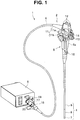
- Fig. 1 is a perspective view of an endoscope apparatus including an endoscope to and from which a sterilization adaptor according to the present embodiment is attachable and detachable.
- an endoscope apparatus 1 includes a main part configured by an endoscope 2 and a camera control unit 3.
- the endoscope 2 includes a main part configured by an insertion portion 4, an operation portion 5, a universal cable 6, and an endoscope connector 16.
- the insertion portion 4 is an elongated long member to be inserted into an observation target section.
- the insertion portion 4 has a configuration in which a distal end portion 7, a bending portion 8, and a flexible tube portion 9 are connected to each other.
- the operation portion 5 includes a grasping portion 5a.
- the grasping portion 5a is connected to a proximal end of the insertion portion 4.
- the operation portion 5 is provided with a bending operation portion 11, various switches 12, an air/water feeding button 13, a suction button 14, and the like.
- the bending operation portion 11 includes, for example, vertical bending operation knob 11a and a horizontal bending operation knob 11b, which are used to perform a bending operation on the bending portion 8.
- Examples of the switches 12 include a release switch, a freeze switch, and an observation mode selection switch for switching between normal observation and fluorescence observation.
- the operation portion 5 is provided with a treatment instrument insertion opening 15 through which a treatment instrument is inserted into or removed from a treatment instrument insertion conduit, not illustrated, provided in the insertion portion 4.
- the universal cable 6 extends from a side portion of the operation portion 5.
- the endoscope connector 16 is provided at an extending end of the universal cable 6.
- a signal transmission cable 17 extends from the endoscope connector 16, an electric connector 18 that is attachable to and detachable from the camera control unit 3 is provided at an end portion of the signal transmission cable 17.
- the endoscope connector 16 is provided with a vent pipe sleeve 20.
- the vent pipe sleeve 20 may be provided on the operation portion 5.
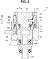
- Fig. 2 is a sectional view illustrating a state where the vent pipe sleeve provided on the endoscope connector illustrated in Fig. 1 is closed.
- Fig. 3 is a sectional view of the vent pipe sleeve illustrated in Fig. 2 in a state where the vent pipe sleeve is opened.
- the vent pipe sleeve 20 includes a main part configured by a pipe sleeve main body 22 to be attached to the endoscope connector 16, a rotary ring 23, a sliding member 24, and a valve body 25 which are provided in the pipe sleeve main body 22.
- the pipe sleeve main body 22 is composed of an elongated stepped pipe formed in a longitudinal axis direction H of the pipe sleeve main body 22, and a stepped through-hole 22b that allows the inside of the endoscope 2 to communicate with the outside is formed in the pipe sleeve main body 22. Further, a guide pin 26 protrudes from an outer peripheral surface 22c of the pipe sleeve main body 22.
- a screw 22n formed in a section on one end side H1 in the longitudinal axis direction H of the pipe sleeve main body 22 is screwed into a fixation member, not illustrated, provided in the endoscope connector 16, so that the pipe sleeve main body 22 is attached to the endoscope connector 16.
- the rotary ring 23 is composed of an annular member and is rotatably disposed in a recessed portion 22a formed in a section on another end side H2 in the longitudinal axis direction H of the pipe sleeve main body 22.
- a long hole 23a is formed on an outer peripheral surface of the rotary ring 23 along the longitudinal axis direction H.
- the sliding member 24 is formed in an elongated pipe shape along the longitudinal axis direction H, and is disposed in a through-hole 23c of the rotary ring 23 and in the stepped through-hole 22b of the pipe sleeve main body 22.
- the section on the one end side H1 in the longitudinal axis direction H of the sliding member 24 is fixed to the stepped through-hole 22b with a screw.
- a peripheral groove 24d having a cam shape is formed on an outer peripheral portion of the sliding member 24.
- the sliding member 24 is integrally formed with the pipe sleeve main body 22. Further, a flange portion 24c is formed on the other end side H2 in the longitudinal axis direction H of the sliding member 24.
- the sliding member 24 includes, inside thereof, a through-hole 24w that is formed along the longitudinal axis direction H and has a tapered surface 24k formed at a part of the sliding member 24 in the longitudinal axis direction H.
- valve body 25 is rotatably provided in the through-hole 24w.
- a peripheral groove 25a is formed on an outer peripheral surface of the valve body 25 in the section on the one end side H1 in the longitudinal axis direction H, and a seal member 27, such as an O-shaped ring, is fitted into the peripheral groove 25a.
- the seal member 27 comes into close contact with the tapered surface 24k, thereby maintaining water-tightness between the sliding member 24 and the valve body 25.
- a screw hole is formed on the outer peripheral surface of the valve body 25 in the section on the other end side H2 in the longitudinal axis direction H, and a cam receiving pin 28 is screwed into the screw hole and is attached thereto.
- the cam receiving pin 28 protrudes to the outside in a radial direction K of the vent pipe sleeve 20 through the peripheral groove 24d formed on the sliding member 24, and a head portion of the cam receiving pin is fitted into the above-described long hole 23a.
- a sterilization adaptor 29 (see Fig. 4 ) is attached to the vent pipe sleeve 20 configured as described above, and a cam pin 44 (see Fig. 4 ) to be described below is fitted into a peripheral groove 23b of the rotary ring 23.
- the cam receiving pin 28 that is fitted into the peripheral groove 24d having a cam shape is rotated along the cam shape.
- valve body 25 is moved to a position illustrated in Fig. 3 along the longitudinal axis direction H.
- vent pipe sleeve 20 described above is merely an example and is not limited to the above-described configuration.
- valve body 25 may be provided in the valve body 25.
- check valve unit may be provided in the valve body 25.
- vent pipe sleeve 20 may have a structure in which the valve body 25 is omitted and the vent pipe sleeve is opened during the sterilization process and can be sealed with a cap or the like during the cleaning and disinfection process.
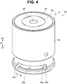
- Fig. 4 is a perspective view of the sterilization adaptor that is attachable to and detachable from the vent pipe sleeve illustrated in Fig. 2 .
- Fig. 5 is a sectional view of the sterilization adaptor taken along the line V-V in Fig. 4 .
- Fig. 6 is a sectional view illustrating a state where the sterilization adaptor illustrated in Fig. 4 is attached to the vent pipe sleeve illustrated in Fig. 2 and the guide pin illustrated in Fig. 2 is fitted into a first position of the guide groove formed in the sterilization adaptor illustrated in Fig. 4 .
- Fig. 7 is a sectional view of the vent pipe sleeve and the sterilization adaptor in a direction different by 90° from the section of the vent pipe sleeve illustrated in Fig. 2 , and illustrates the state where the guide pin illustrated in Fig. 2 is moved to a second position of the guide groove.
- Fig. 8 is a sectional view of the vent pipe sleeve and the sterilization adaptor in a direction different by 90° from the section of the vent pipe sleeve illustrated in Fig. 2 , and illustrates the state where the guide pin illustrated in Fig. 2 is moved to a third position of the guide groove and the check valve unit is closed.
- Fig. 9 is a sectional view of the vent pipe sleeve and the sterilization adaptor in a state where the check valve unit illustrated in Fig. 8 is opened.
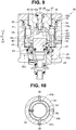
- Fig. 10 is a sectional view of the sterilization adaptor taken along the line X-X in Fig. 5 .
- the sterilization adaptor 29 includes a main part configured by a main body portion 30 including a hole portion 30a along the longitudinal axis direction, a vent valve unit 32 disposed in the hole portion 30a of the main body portion 30, and a check valve unit 33 disposed in the vent valve unit 32.
- the sterilization adaptor 29 is attachable to and detachable from the vent pipe sleeve 20.
- the main body portion 30 includes a main part configured by a main body member 34, a spring pressing member 35, engaging pins 36, a first seal member 37, a second seal member 38, and a retaining ring 39.
- the main body member 34 is formed of a cylindrical member in which a through-hole is formed in a stepped shape along the longitudinal axis direction H.
- the main body member 34 is provided with a guide groove 34d as an engaging portion on the outer peripheral surface in the section on the one end side H1 in the longitudinal axis direction H.
- the guide pin 26 of the vent pipe sleeve 20 is inserted into the guide groove 34d, thereby enabling engagement by a spring member 45 to be described below.
- the main body member 34 is provided with a groove 34c formed on an inner peripheral surface which is formed by a through-hole in the section on the one end side H1 in the longitudinal axis direction H.
- the first seal member 37 which is formed of, for example, an O-shaped ring, is disposed in the groove 34c.
- the sterilization adaptor 29 When the sterilization adaptor 29 is attached to the vent pipe sleeve 20, as illustrated in Figs. 6 to 9 , the first seal member 37 contacts the outer peripheral surface 22c of the pipe sleeve main body 22. With this configuration, the water-tightness between the vent pipe sleeve 20 and the main body portion 30 is maintained.
- the spring pressing member 35 is formed of a ring-shaped member having a tapered surface 35a in the section on the one end side H1 in the longitudinal axis direction H.
- the spring pressing member 35 is disposed on a bottom surface 34b of the recessed portion formed in the section on the other end side H2 in the longitudinal axis direction H in the through-hole of the main body member 34.
- a groove 35b is formed on the outer peripheral surface of the spring pressing member 35, and the second seal member 38, which is formed of, for example, an O-shaped ring, is disposed in the groove 35b in a state where the second seal member 38 contacts the inner peripheral surface of the main body member 34.
- the retaining ring 39 of the ring-shaped member which includes on the outer peripheral surface thereof a male screw portion not illustrated, is screwed and fixed into a female screw portion which is formed in the inner peripheral surface of the main body member 34.
- the retaining ring 39 regulates the movement of the spring pressing member 35 in the longitudinal axis direction H.
- the hole portion 30a described above is formed in the inner peripheral surface of each of the spring pressing member 35 and the retaining ring 39.
- a vent valve 31 to be described below is provided in the hole portion 30a.
- a gap 32a which causes the inside and the outside of the sterilization adaptor 29 communicate with each other, is formed between the inner peripheral surface of each of the spring pressing member 35 and the retaining ring 39 and a vent valve body 40, which is described below, of the vent valve 31.
- the vent valve unit 32 includes a main part configured by the vent valve 31, a rotation prevention member 43, the spring member 45 as an elastic member, and a valve body holding member 42 as a vent valve holding member.
- the vent valve 31 is formed of the vent valve body 40 and a seal member 41.
- the vent valve body 40 is formed of a cylindrical member including a stepped through-hole 40a as a fluid channel for circulating gas in the vent valve body along the longitudinal axis direction H.
- the seal member 41 which is formed of, for example, an O-shaped ring, is disposed in a peripheral groove 40b formed on the outer peripheral surface in the section on the one end side H1 in the longitudinal axis direction H.
- a screw hole 40c is formed in the inner peripheral surface of the vent valve body 40 in the section on the one end side H1 in the longitudinal axis direction H.
- the valve body holding member 42 is formed of a stepped cylindrical member, a protruding portion 42a provided with a male screw is formed on the outer peripheral surface in the section on the other end side H2 in the longitudinal axis direction H, and a flange portion 42b is formed on the outer peripheral surface in the section on the one end side H1 in the longitudinal axis direction H.
- the valve body holding member 42 is fixed to the vent valve body 40 by the protruding portion 42a being screwed into the screw hole 40c of the vent valve body 40.
- valve body holding member 42 is provided with a plurality of through-holes 42c as communication paths for causing a space 42d to communicate with the gap 32a described above. Note that the through-holes 42c also communicates with the through-hole 40a.
- the rotation prevention member 43 is formed of a stepped cylindrical member, and includes an inward flange which is formed in the section on the other end side H2 in the longitudinal axis direction H.
- the flange portion 42b of the valve body holding member 42 is in contact with and is fixed by bonding to a surface of the inward flange, the surface of the inward flange being located in the section on the one end side H1 in the longitudinal axis direction H.
- a step 43a is formed on the outer peripheral surface in the section on the other end side H2 in the longitudinal axis direction H of the rotation prevention member 43.
- the spring member 45 is disposed along the longitudinal axis direction H in a state where the spring member 45 is contracted between the step 43a and grooves 35c formed on the surface of the spring pressing member 35 in the section on the one end side H1 in the longitudinal axis direction H.
- the cam pin 44 is disposed in the through-hole formed in the radial direction K such that a distal end of the cam pin protrudes toward the inside of the rotation prevention member 43.
- grooves 43b into which distal end portions of the engaging pins 36 each protruding from the main body portion 30 toward the inside in the radial direction K are respectively fitted are formed along the longitudinal axis direction H.
- a plurality of grooves 43b are formed along the peripheral direction of the rotation prevention member 43. That is, also three engaging pins 36 to be fitted into the grooves 43b are provided.
- the rotation prevention member 43 is moved separately from the main body member 34 in the longitudinal axis direction H, and is moved in the same direction as the main body member 34 in the rotation direction.
- the number of the grooves 43b formed in the rotation prevention member 43 and the number of the engaging pins 36 are not limited to three, but instead may be one, two, or four or more.
- the rotation prevention member 43 is biased to the one end side H1 in the longitudinal axis direction H by a biasing force of the spring member 45 to the one end side H1 in the longitudinal axis direction H.
- valve body holding member 42 and the vent valve body 40 which are fixed to the rotation prevention member 43, are also biased to the one end side H1 in the longitudinal axis direction H. Accordingly, the seal member 41 is pressed against the tapered surface 35a formed on the inner peripheral surface of the spring pressing member 35.
- the gap 32a is blocked, thereby maintaining the water-tightness between the spring pressing member 35 and the vent valve body 40.
- the check valve unit 33 is provided in the through-hole 40a of the vent valve body 40.
- check valve unit 33 inhibits circulation of gas from the outside to the inside of the endoscope 2 through the through-hole 40a, and allows gas to circulate from the inside to the outside of the endoscope 2 when the pressure in the endoscope 2 is higher than the pressure outside the endoscope 2.
- the check valve unit 33 includes a main part configured by a shaft body 46, a spring member 47, a seal member 49, and a spring presser 48.
- the shaft body 46 is slidably provided along the longitudinal axis direction H within the through-hole 40a.
- a male screw portion 46a is formed on the outer peripheral surface of the shaft body 46 in the section on the one end side H1 in the longitudinal axis direction H, and the spring presser 48 is screwed into the male screw portion 46a.
- the spring member 47 is disposed in the longitudinal axis direction H, with the spring member being contracted between the spring presser 48 and a recessed portion formed in the section on the one end side H1 in the longitudinal axis direction H in the vent valve body 40.
- seal member 49 which is formed of, for example, an O-shaped ring, is disposed in an annular groove 46b formed on the outer peripheral surface of the shaft body 46 in the section on the other end side H2 in the longitudinal axis direction H.
- the seal member 49 contacts and is pressed against a tapered surface 40t, which is formed at the through-hole 40a in the vent valve body 40, when the spring presser 48 and the shaft body 46 are biased to the one end side H1 in the longitudinal axis direction by a biasing force of the spring member 47 to the one end side H1 in the longitudinal axis direction H.
- the cam pin 26 of the vent pipe sleeve 20 is inserted into the guide groove 34d along the longitudinal axis direction H until the guide pin 26 contacts the guide groove 34d at a first position 34f of the guide groove 34d formed in the main body member 34, against the biasing force of the spring member 45 toward the one end side H1 in the longitudinal axis direction H.
- the cam pin 44 is fitted into the peripheral groove 23b of the rotary ring 23.
- the flange portion 24c of the sliding member 24 lifts the valve body holding member 42 toward the other end side H2 in the longitudinal axis direction H, against the biasing force of the spring member 45 to the one end side H1 in the longitudinal axis direction H.
- vent valve body 40 is also moved toward the one end side H1 in the longitudinal axis direction H, so that the seal member 41 is spaced apart from the tapered surface 35a.
- the gap 32a and the through-holes 42c communicate with each other.
- the vent valve body 40 is opened.
- the vent pipe sleeve 20 is in the closed state, and thus the inside and the outside of the endoscope 2 do not communicate with each other.
- the operator rotates the main body member 34 in the peripheral direction until the guide pin 26 is guided to a second position 34g of the guide groove 34d, as illustrated in Fig. 4 , while keeping the state against the biasing force of the spring member 45 toward the one end side H1 along the longitudinal axis direction H.
- the seal member 27 is spaced apart from the tapered surface 24k of the sliding member 24, so that the vent pipe sleeve 20 is opened.
- the inside of the endoscope 2 communicates with the space 42d of the valve body holding member 42, and the through-holes 42c communicates with the outside of the endoscope 2 through the gap 32a.
- the main body portion 30 is moved to the other end side H2 in the longitudinal axis direction H until the guide pin 26 contacts the guide groove 34d at a third position 34h of the guide groove 34d by the biasing force of the spring member 45 to the one end side H1 in the longitudinal axis direction H.
- the seal member 41 is pressed against the tapered surface 35a of the spring pressing member 35 by the spring member 45, so that the gap 32a is blocked and the inside of the endoscope 2 is blocked from the outside. In other words, the vent valve body 40 is closed.
- the sterilization adaptor 29 is attached to the vent pipe sleeve 20.
- the endoscope 2 is put in a gas sterilization apparatus.
- the cam pin 26 engages with the guide groove 34d that is formed at a depth where the cam pin can be easily hooked. This configuration prevents the sterilization adaptor 29 from being rotated and detached during the sterilization process.
- the pressure in the sterilization apparatus is decreased to be brought close to the vacuum state.
- the check valve unit 33 and the vent valve body 40 are in the closed state even when the vent pipe sleeve 20 is opened. Accordingly, the inside of the endoscope 2 and the inside of the sterilization apparatus do not communicate with each other. Therefore, the pressure in the endoscope 2 becomes higher than the pressure in the sterilization apparatus.
- a fluid passage 40d that causes the inside and the outside of the sterilization adaptor 29 to communicate with each other is formed between the vent valve body 40 and the shaft body 46.
- the inside of the endoscope 2 communicates with the inside of the sterilization apparatus through the gap between the sliding member 24 and the valve body 25, the space 42d in the sterilization adaptor 29, and the fluid passage 40d, from the inside of the endoscope 2.
- the pressure in the endoscope 2 is not higher than, that is, is equal to the pressure in the sterilization apparatus in the conditioning step. Accordingly, as described above, the bending rubber constituting the bending portion 8 can be prevented from being blown out.
- the inside of the endoscope 2 and the inside of the sterilization apparatus are blocked from each other and thus sterilization gas is not introduced into the endoscope 2, thereby making it possible to prevent deterioration of internal members of the endoscope due to the gas.
- the operator detaches the sterilization adaptor 29 from the vent pipe sleeve 20.
- the operator grips the main body portion 30 and depresses the main body portion 30 against the biasing force of the spring member 45 toward the one end side H1 in the longitudinal axis direction H so that the state is shifted from the state illustrated in Fig. 8 to the state illustrated in Fig. 7 .
- a communication path 32b is formed by the through-holes 42c formed around the valve body holding member 42, and the gap 32a communicates with the space 42d in the main body portion 30, so that the gap 32a and the space 42d communicate with each other.
- the vent valve body 40 is opened.
- the operator grips the main body member 34 and rotates the main body member 34 in a direction opposite to that at the time of the attachment, and moves the guide pin 26 to the first position 34f illustrated in Fig. 6 from the second position 34g illustrated in Fig. 7 .
- valve body 25 is moved from the state illustrated in Fig. 3 to the state illustrated in Fig. 2 by the rotary ring 23 being rotated in the direction opposite to that described above, and the seal member 27 is brought into contact with the tapered surface 24k, and thereby the vent pipe sleeve 20 is closed.
- the main body member 34 is drawn out toward the other end side H2 in the longitudinal axis direction H, thereby detaching the cam pin 26 from the guide groove 34d.
- the sterilization adaptor 29 is removed from the vent pipe sleeve 20.
- the configuration of the sterilization adaptor 29 according to the present embodiment prevents the bending rubber constituting the bending portion 8 from being crimped to the plurality of bending pieces when the sterilization adaptor 29 is removed from the vent pipe sleeve 20 after the sterilization process.
- the communication path 32b allows the gap 32a and the fluid passage 40d to communicate with each other, which eliminates the need for separately providing two channels, i.e., a channel leading to the inside of the endoscope 2 from the vent valve unit 32 and a channel leading to the inside of the endoscope 2 from the check valve unit 33. Consequently, downsizing of the sterilization adaptor 29 is achieved.
- the seal member 41 is constantly spaced apart from the tapered surface 35a. Therefore, it is possible to efficiently replace air between the inside and the outside of the endoscope 2.
- the vent pipe sleeve 20 is reliably closed, thereby making it possible to prevent medicinal solution from entering into the endoscope 2 during the cleaning and disinfection process.
- the main body member 34 and the valve body holding member 42 are rotated separately, a force in the rotation direction is applied to the spring member 45 when attaching and detaching the sterilization adaptor.
- the force to be applied to the spring member can be reduced. Accordingly, even when the attachment and detachment are repeated, the spring member 45 and the seal member 41 are less likely to deteriorate and thus it is possible to prevent a failure from occurring in the sterilization adaptor 29.
- the sterilization adaptor 29 can be detached from the vent pipe sleeve 20 without causing any problem and the endoscope 2 can be put into the cleaning and disinfection apparatus to perform the cleaning and disinfection process.
- the check valve unit 33 is disposed in the vent valve unit 32, thereby reducing the size of the sterilization adaptor 29 in the longitudinal axis direction H, as compared with a configuration in which the check valve unit 33 is disposed on the other end side H2 in the longitudinal axis direction H with respect to the vent valve unit 32.
- the sterilization adaptor 29 can be downsized.
- the sterilization adaptor 29 including the vent valve unit 32 and the check valve unit 33 like in the present embodiment described above can be applied to various endoscopes provided with the vent pipe sleeve 20, and thus the gas sterilization process can be performed on various types of endoscopes.
- the configuration according to the present embodiment can also be applied to a configuration in which a vent valve is provided on a side of the vent pipe sleeve 20.
- the downsized sterilization adaptor 29 capable of preventing gas from entering into the endoscope 2 in the sterilization process and setting the pressure in the endoscope 2 to be equal to the pressure outside the endoscope 2 in the attachment to or detachment from the endoscope 2.
- Fig. 11 is a perspective view of a sterilization adaptor configured to be attachable to and detachable from a vent pipe sleeve according to the present embodiment.
- Fig. 12 is a sectional view illustrating a state where the sterilization adaptor illustrated in Fig. 11 is attached to the vent pipe sleeve and the guide pin is fitted into the first position of the guide groove formed in the sterilization adaptor.
- Fig. 13 is a sectional view of the vent pipe sleeve and the sterilization adaptor in a state where the guide pin illustrated in Fig. 12 is moved to the second position of the guide groove.
- Fig. 14 is a sectional view of the vent pipe sleeve and the sterilization adaptor in a state where the guide pin illustrated in Fig. 13 is moved to the third position of the guide groove.
- FIG. 15 is a sectional view of the sterilization adaptor taken along the line XV-XV in Fig. 12 .
- Fig. 16 is a perspective view of the vent pipe sleeve illustrated in Fig. 12 .
- the configuration of the sterilization adaptor according to the second embodiment is different in the configuration of the vent valve unit from the sterilization adaptor according to the first embodiment illustrated in Figs. 1 to 11 described above. Accordingly, only the difference will be described, and components similar to those of the first embodiment are denoted by the same reference numerals and the descriptions thereof are omitted.
- the sterilization adaptor 29 includes a main part configured by the vent valve unit 32, the check valve unit 33, and the main body portion 30 like in the first embodiment described above.
- the main body portion 30 includes a main part configured by the main body member 34, the spring pressing member 35, the cam pin 44, and the first seal member 37.
- the main body member 34 is formed of a pipe-shaped member including a stepped portion on the inner peripheral surface.
- the main body member 34 is provided with the guide groove 34d into which the guide pin 26 of the vent pipe sleeve 20 is fitted when the sterilization adaptor 29 is attached to the vent pipe sleeve 20, like in the first embodiment, on the outer peripheral surface in the section on the one end side H1 in the longitudinal axis direction H.
- the cam pin 44 is provided on the main body member 34 along the radial direction K such that the distal end of the cam pin protrudes toward the inside of the main body member 34.
- first seal member 37 is disposed in an annular groove formed on the inner peripheral surface of the main body member 34 in the section on the one end side H1 in the longitudinal axis direction H.
- the spring pressing member 35 is formed of a pipe-shaped member with an inner peripheral surface formed in a stepped shape.
- a male screw formed on the outer peripheral surface of the spring pressing member is screwed and fixed into a female screw 34o formed on the inner peripheral surface of the main body member 34 in the section on the other end side H2 in the longitudinal axis direction H.
- grooves 35c leading from an end portion on the one end side H1 in the longitudinal axis direction H of the spring pressing member 35 to a stepped bottom surface 35d provided on the section on the other end side H2 in the longitudinal axis direction H are formed on the inner peripheral surface of the spring pressing member 35 at predetermined intervals in the peripheral direction of the spring pressing member 35 as illustrated in Fig. 15 .
- the main body portion 30 includes inside thereof a bottom surface 34r formed along the radial direction K and the hole portion 30a formed along the longitudinal axis direction H.
- the vent valve unit 32 including the main part formed of the spring member 45 and the vent valve 31 is disposed.
- the vent valve 31 includes a main part configured by the seal member 41 and the vent valve body 40.
- Flange portions 40f are formed in the section on the one end side H1 in the longitudinal axis direction H of the vent valve body 40, and the gap 32a is formed between each of the flange portions 40f and the spring pressing member 35 as illustrated in Fig. 15 .
- the flange portions 40f are fitted into the respective grooves 35c of the spring pressing member 35.
- the vent valve body 40 is movable in the longitudinal axis direction with respect to the spring pressing member 35, and is formed to be integrally turnable in the peripheral direction.
- each of the flange portions 40f is formed between each of the flange portions 40f and the spring pressing member 35, a part of each of the flange portions 40f may be formed into a D-cut shape.
- the number of the flange portions 40f and the number of the grooves 35c are not limited to four, but instead a plurality of flange portions 40f and a plurality of grooves 35c may be provided.
- the spring member 45 is disposed along the longitudinal axis direction H in a state where the spring member is contracted between the flange portions 40f and the stepped bottom surface 35d of the spring pressing member 35.
- the main body member 34 is fixed to the outer peripheral surface of the vent pipe sleeve 20 by the first seal member 37.
- vent valve body 40 is moved to the one end side H1 in the longitudinal axis direction H by the biasing force of the spring member 45 toward the one end side H1 in the longitudinal axis direction H.
- the seal member 41 is pressed against the tapered surface 34k formed on the bottom surface 34r of the main body member 34, thereby maintaining air-tightness between the main body member 34 and the vent valve body 40. In other words, the vent valve body 40 is closed.
- the check valve unit 33 is disposed in the vent valve unit 32.
- the check valve unit 33 includes a main part configured by the shaft body 46, the spring member 47, the spring presser 48, the seal member 49, a valve body 52, and a seal member 153.
- the configuration of the check valve unit 33 is the same as that of the first embodiment, and the seal member 153 maintains air-tightness between the vent valve body 40 and the valve body 52.
- the communication path 32b is formed in the protruding portion formed in the section on the one end side H1 in the longitudinal axis direction H of the vent valve body 40.
- a groove 24a into which the cam pin 44 is fitted is formed at two positions, i.e., the position corresponding to the cam pin 26 in the peripheral direction and the position shifted in the peripheral direction by 90° from the position corresponding to the cam pin 26.
- the operator presses the main body member 34 toward the one end side H1 in the longitudinal axis direction H to cause the guide pin 26 of the vent pipe sleeve 20 to be fitted into the first position 34f of the guide groove 34d illustrated in Fig. 12 , like in the first embodiment.
- the operator rotates to move the main body member 34 to the second position 34g of the guide groove 34d illustrated in Fig. 13 , and then releases the grip to move the main body member 34 to the third position 34h of the guide groove 34d as illustrated in Fig. 14 .
- gas is discharged from the inside of the endoscope 2 into the sterilization apparatus through the gap between the sliding member 24 and the valve body 25 of the vent pipe sleeve 20, the space 42d in the main body portion 30, the communication path 32b, and the fluid passage 40d.
- the pressure in the endoscope 2 is not higher than, or is equal to the pressure in the sterilization apparatus in the conditioning step. Accordingly, as described above, the bending rubber constituting the bending portion 8 can be prevented from being blown out.
- the check valve unit 33 automatically closes due to the difference in pressure, so that the inside of the endoscope 2 and the inside of the sterilization apparatus are blocked from each other.
- the inside of the endoscope 2 and the inside of the sterilization apparatus are blocked from each other, and thus sterilization gas is not introduced into the endoscope 2, thereby making it possible to prevent deterioration of internal members of the endoscope due to the gas.
- the protruding portion 42a is brought into contact with the valve body 25 of the vent pipe sleeve 20 and the seal member 41 is spaced apart from the tapered surface 34k against the biasing force of the spring member 45 toward the one end side H1 in the longitudinal axis direction H, so that the gap 32a is formed between the main body member 34 and the vent valve body 40 and the inside and the outside of the endoscope 2 communicate with each other.
- the vent valve body 40 is opened.
- the frictional force between the vent pipe sleeve 20 and the protruding portion 42a at the time of rotation is smaller than that in the first embodiment, which enables the operator to detach the sterilization adaptor 29 with a small force.
- the main body portion 30 and the vent valve body 40 are rotated together.
- the spring member 45 and the seal member 41 are less likely to deteriorate and thus it is possible to prevent a failure from occurring in the sterilization adaptor 29.
- the configuration in which the spring pressing member 35 and the vent valve body 40 are screwed together has the same functions as the engaging pins 36 and the rotation prevention member 43 illustrated in the first embodiment described above.
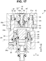
- Fig. 17 is a sectional view illustrating a state where a sterilization adaptor according to the present embodiment is attached to the vent pipe sleeve.
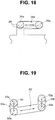
- Fig. 18 is a diagram schematically illustrating the guide groove formed in the main body member of the sterilization adaptor illustrated in Fig. 17 , and the guide pin provided on the vent pipe sleeve.
- Fig. 19 is a diagram schematically illustrating the cam groove which is different from the one illustrated in Fig. 18 and is formed in the main body member of the sterilization adaptor illustrated in Fig. 17 , and the cam pin provided on the grasping portion.
- Fig. 20 is a sectional view of the vent pipe sleeve and the sterilization adaptor in a state where the vent valve body illustrated in Fig. 17 is opened.
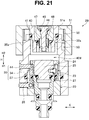
- Fig. 21 is a sectional view of the vent pipe sleeve and the sterilization adaptor in a state where the vent pipe sleeve is closed from the state illustrated in Fig. 20 .
- the configuration of the sterilization adaptor according to the third embodiment is different in the configuration of the vent valve unit, from the sterilization adaptor of the first embodiment illustrated in Figs. 1 to 11 described above and the sterilization adaptor of the second embodiment illustrated in Figs. 12 to 16 . Accordingly, only the difference will be described, and components which are the same as those of the first and second embodiments are denoted by the same reference numerals and the descriptions thereof are omitted.
- the sterilization adaptor 29 includes a main part configured by the vent valve unit 32, the check valve unit 33, the main body portion 30, and a grasping portion 51.
- the main body portion 30 includes a main part configured by the main body member 34, the first seal member 37, and the cam pin 44.
- the main body member 34 is formed of a pipe-shaped member in which the hole portion 30a, which is a stepped through-hole, is formed on the inner peripheral surface along the longitudinal axis direction H, and the tapered surface 35a is formed on the inner peripheral surface of the main body member.
- a groove is formed on the inner peripheral surface of the main body member 34 in the section on the one end side H1 in the longitudinal axis direction H, and the first seal member 37, such as an O-shaped ring, is disposed in the groove.
- the main body member 34 includes the guide groove 34d, as illustrated in Fig. 18 , formed in the section on the one end side H1 in the longitudinal axis direction H with respect to the groove in which the first seal member 37 is disposed, and a cam groove 53 illustrated in Fig. 19 is formed in the section on the other end side H2 in the longitudinal axis direction H.
- the cam pin 44 is provided along the radial direction K such that the distal end of the cam pin protrudes toward the hole portion 30a at the same position as the position illustrated in the second embodiment described above.
- the grasping portion 51 is formed in a pipe shape including an inward flange in the section on the other end side H2 in the longitudinal axis direction H, and a pin 54 is disposed in a hole penetrating through in the radial direction K in the section on the one end side H1 in the longitudinal axis direction H such that the pin protrudes toward the inside the grasping portion 51.
- the pin 54 is engageable with the guide groove 53 as illustrated in Fig. 19 , and is slidable to positions 53a to 53c along the guide groove 53.
- the vent valve unit 32 includes a main part configured by the vent valve body 40 and the seal member 41.
- the vent valve body 40 is formed of a pipe-shaped member, and includes, on the groove formed on the outer peripheral surface thereof, the seal member 41 such as an O-shaped ring.
- vent valve body 40 is fixed by bonding to a hole 51a in a hole portion of the inward flange portion provided on the grasping portion 51. Such a configuration enables the vent valve body 40 to move and rotate integrally with the grasping portion 51.
- a spring member 50 is disposed so as to be contracted between a recessed portion 34i formed on an end face on the other end side H2 in the longitudinal axis direction H of the main body member 34 in the longitudinal axis direction H and the inward flange portion of the grasping portion 51.
- the spring member 50 causes the pin 54 to be fitted into the positions 53a and 53c illustrated in Fig. 19 .
- the gap 32a causes the inside of the endoscope 2 to communicate with the outside of the endoscope 2.
- check valve unit 33 has the same structure as that of the second embodiment described above, and is disposed in the vent valve body 40 in the vent valve unit 32.
- the fluid passage 40d in the vent valve unit 32 and the hole portion 30a communicate with each other through the space 42d in the main body member 34.
- the grasping portion 51 is also moved to the one end side H1 in the longitudinal axis direction H, and the pin 54 is moved from the position 53c to the position 53d in the guide groove 53 illustrated in Fig. 19 .
- the vent valve unit 32 is opened.
- the main body member 34 is integrally rotated with the grasping portion 51, so that the cam pin 26 is guided to a position 34p in the guide groove 34d illustrated in Fig. 18 and thus the vent pipe sleeve 20 is opened.
- the sterilization adaptor 29 is attached in two stages in which the grasping portion 51 is rotated and thereafter the main body member 34 is rotated.
- the sterilization adaptor 29 engages with the guide groove 53 at a depth where the pin 54 can be easily hooked by the biasing force of the spring member 50 toward the one end side H1 in the longitudinal axis direction H, thereby preventing the grasping portion 51 from being rotated and detached during the sterilization process.
- This configuration can prevent a situation where the vent valve body 40 is opened during the sterilization process and gas enters into the endoscope 2 and deteriorates the components.
- the operator first presses the grasping portion 51 into the one end side H1 in the longitudinal axis direction H against the biasing force of the spring member 50 toward the one end side H1 in the longitudinal axis direction H.
- the pin 54 is moved from the position 53a to the position 53b in the guide groove 53. After that, when the grasping portion 51 is rotated along the guide groove 53 in the direction opposite to that at the time of attachment, the pin 54 is moved to the position 53d.
- the pressure in the endoscope 2 is a negative pressure, and thus air flows into the endoscope 2 through the gap 32a, the space 42d, and the gap between the valve body 25 and the sliding member 24 of the vent pipe sleeve 20.
- the vent valve body 40 can be reliably opened before the vent pipe sleeve 20 starts to be closed when the sterilization adaptor 29 is detached, thereby making it possible to reliably release the negative pressure state in the endoscope 2.
- valve body 25 of the vent pipe sleeve 20 is moved to the one end side H1 in the longitudinal axis direction H by the cam pin 44, so that the seal member 27 contacts the tapered surface 24k and the vent pipe sleeve 20 is closed.
- Such a configuration can also provide advantageous effects similar to those of the first and second embodiments described above.
- the first to third embodiments are described by taking an endoscope as an example of a medical device.
- the medical device is not limited to an endoscope.
- the present invention is also applicable to medical devices provided with a vent pipe sleeve, other than an endoscope.
Landscapes
- Health & Medical Sciences (AREA)
- Life Sciences & Earth Sciences (AREA)
- Surgery (AREA)
- Animal Behavior & Ethology (AREA)
- General Health & Medical Sciences (AREA)
- Public Health (AREA)
- Veterinary Medicine (AREA)
- Physics & Mathematics (AREA)
- Heart & Thoracic Surgery (AREA)
- Engineering & Computer Science (AREA)
- Biomedical Technology (AREA)
- Optics & Photonics (AREA)
- Pathology (AREA)
- Medical Informatics (AREA)
- Molecular Biology (AREA)
- Radiology & Medical Imaging (AREA)
- Biophysics (AREA)
- Nuclear Medicine, Radiotherapy & Molecular Imaging (AREA)
- Epidemiology (AREA)
- Chemical Kinetics & Catalysis (AREA)
- General Chemical & Material Sciences (AREA)
- Chemical & Material Sciences (AREA)
- Pulmonology (AREA)
- Anesthesiology (AREA)
- Hematology (AREA)
- Mechanical Engineering (AREA)
- Astronomy & Astrophysics (AREA)
- General Physics & Mathematics (AREA)
- Endoscopes (AREA)
- Instruments For Viewing The Inside Of Hollow Bodies (AREA)
Abstract
Description
- The present invention relates to a sterilization adaptor configured to be attachable to and detachable from a medical device.
- Medical devices, such as endoscopes, need to be cleaned and disinfected by using a washer disinfector, since the medical devices will be reused after use.
- In addition, there is a recent demand for performing not only the cleaning and disinfection process, but also an endoscope sterilization process to take measures against infectious diseases when the endoscope is used.
- In general, in a gas sterilization process, first, in a conditioning step, the air in a chamber of a sterilization apparatus is removed, and the pressure in the chamber is brought close to a vacuum state.
- After that, in a sterilization step, the endoscope sterilization process is carried out by pouring gas into the chamber, and then in a desorption step after completion of the sterilization process, the gas in the chamber is replaced with water vapor.
- Lastly, in a drying/aeration step, the pressure in the chamber is restored to the atmospheric pressure by pouring air into the chamber.
- In this case, in the gas sterilization process, the gas used in the sterilization step corrodes the components in the endoscope. Accordingly, there is a need to prevent the gas from entering into the endoscope.
- However, if the inside of the endoscope is airtightly maintained in the gas sterilization process, bending rubber of the endoscope is blown out when the pressure in the chamber, i.e., the pressure outside the endoscope is decreased to a negative pressure in the conditioning step.
- In view of the above, a configuration in which an endoscope is provided with a vent pipe sleeve including a check valve unit for circulating gas from the inside of the endoscope to the outside of the endoscope is well known.
- The check valve unit inhibits the circulation of gas from the outside of the endoscope to the inside of the endoscope, thereby preventing the gas from entering into the endoscope in the sterilization step.
- Further, in a case where the pressure in the endoscope is higher than the pressure outside the endoscope, for example, when the inside of the chamber is close to the vacuum state and the inside of the endoscope is maintained in the atmospheric pressure state in the conditioning step, the check valve is opened due to a difference in pressure, thereby circulating the gas from the inside of the endoscope to the outside of the endoscope.
- Accordingly, when the inside of the chamber is brought close to the vacuum state in the conditioning step, the pressure in the endoscope can be set to be equal to the pressure in the chamber, thereby making it possible to prevent the bending rubber from being blown out.
- However, when the pressure in the chamber, i.e., the pressure outside the endoscope, is increased to the atmospheric pressure after the completion of the sterilization step, the pressure outside the endoscope is equal to the atmospheric pressure although the inside of the endoscope is close to the vacuum state.
- Therefore, since the pressure in the endoscope is lower than the pressure outside the endoscope, the check valve unit is not opened and the bending rubber is crimped to a plurality of bending pieces. After the gas sterilization process, when the endoscope is taken out from the chamber and is used, the bending rubber is still crimped to the plurality of bending pieces. Accordingly, if a bending portion is bent, the bending rubber may bite into the bending pieces and may be damaged.
- Accordingly, Japanese Patent Application Laid-Open Publication No.
2013-46701 - However, in the configuration of the endoscope described in Japanese Patent Application Laid-Open Publication No.
2013-46701 - Therefore, there is a problem that, in the case of performing the cleaning and disinfection process on the endoscope, an increase in the size of the vent pipe sleeve makes it difficult to insert the endoscope into a cleaning and disinfection apparatus.
- Note that, in view of the above-described problem, a configuration in which a sterilization adaptor is provided with a vent valve unit and a check valve unit is well known. However, in this case, there is a problem that the size of the sterilization adaptor is increased.
- Note that the above-described problem is raised not only in the endoscope, but also in other medical devices on which the sterilization process is performed.
- The present invention has been made in view of the above-described problems, and an object of the present invention is to provide a downsized sterilization adaptor capable of preventing gas from entering into a medical device in a sterilization process and setting a pressure in the medical device to be equal to a pressure outside the medical device.
- A sterilization adaptor according to an aspect of the present invention is a sterilization adaptor configured to be attachable to and detachable from a medical device, the sterilization adaptor including: a check valve unit for inhibiting circulation of gas from an outside of the medical device to an inside of the medical device when the sterilization adaptor is attached to the medical device, and for circulating the gas from the inside to the outside; a main body portion including a hole portion; and a vent valve unit disposed in the hole portion, the vent valve unit causing the inside and the outside to communicate with each other through a gap formed between the vent valve unit and the main body portion and blocking the gap. The check valve unit is disposed in the vent valve unit.
-
-
Fig. 1 is a perspective view illustrating an endoscope apparatus including an endoscope to and from which a sterilization adaptor according to a first embodiment is attachable and detachable; -
Fig. 2 is a sectional view illustrating a state where a vent pipe sleeve provided on an endoscope connector illustrated inFig. 1 is closed; -
Fig. 3 is a sectional view illustrating a state where the vent pipe sleeve illustrated inFig. 2 is opened; -
Fig. 4 is a perspective view of the sterilization adaptor that is attachable to and detachable from the vent pipe sleeve illustrated inFig. 2 ; -
Fig. 5 is a sectional view of the sterilization adaptor taken along a line V-V inFig. 4 ; -
Fig. 6 is a sectional view illustrating a state where the sterilization adaptor illustrated inFig. 4 is attached to the vent pipe sleeve illustrated inFig. 2 and a guide pin illustrated inFig. 2 is fitted into a first position of a guide groove formed in the sterilization adaptor illustrated inFig. 4 ; -
Fig. 7 is a sectional view of the vent pipe sleeve and the sterilization adaptor in a direction different by 90° from the section of the vent pipe sleeve illustrated inFig. 2 , and illustrates a state where the guide pin illustrated inFig. 2 is moved to a second position of the guide groove; -
Fig. 8 is a sectional view of the vent pipe sleeve and the sterilization adaptor in a direction different by 90° from the section of the vent pipe sleeve illustrated inFig. 2 , and illustrates a state where the guide pin illustrated inFig. 2 is moved to a third position of the guide groove and a check valve unit is closed; -
Fig. 9 is a sectional view of the vent pipe sleeve and the sterilization adaptor in a state where the check valve unit illustrated inFig. 8 is opened; -
Fig. 10 is a sectional view of the sterilization adaptor taken along a line X-X inFig. 5 ; -
Fig. 11 is a perspective view of a sterilization adaptor that is attachable to and detachable from a vent pipe sleeve according to a second embodiment; -
Fig. 12 is a sectional view illustrating a state where the sterilization adaptor illustrated inFig. 11 is attached to the vent pipe sleeve and the guide pin is fitted into the first position of the guide groove formed in the sterilization adaptor; -
Fig. 13 is a sectional view of the vent pipe sleeve and the sterilization adaptor in a state where the guide pin illustrated inFig. 12 is moved to the second position of the guide groove; -
Fig. 14 is a sectional view of the vent pipe sleeve and the sterilization adaptor in a state where the guide pin illustrated inFig. 13 is moved to the third position of the guide groove; -
Fig. 15 is a sectional view of the sterilization adaptor taken along a line XV-XV inFig. 12 ; -
Fig. 16 is a perspective view of the vent pipe sleeve illustrated inFig. 12 ; -
Fig. 17 is a sectional view illustrating a state where a sterilization adaptor according to a third embodiment is attached to a vent pipe sleeve; -
Fig. 18 is a diagram schematically illustrating a guide groove formed in a main body member of the sterilization adaptor illustrated inFig. 17 and a guide pin provided on the vent pipe sleeve; -
Fig. 19 is a diagram schematically illustrating a cam groove, which is formed in the main body member of the sterilization adaptor illustrated inFig. 17 and is different from the cam groove illustrated inFig. 18 , and the cam pin provided on a grasping portion; -
Fig. 20 is a sectional view of the vent pipe sleeve and the sterilization adaptor in a state where the vent valve body illustrated inFig. 17 is opened; and -
Fig. 21 is a sectional view of the vent pipe sleeve and the sterilization adaptor in a state where the vent pipe sleeve is closed from the state illustrated inFig. 20 . - Embodiments of the present invention will be described below with reference to the drawings. Note that in the drawings to be referred to in the following description, some components are illustrated with different scales so that the components can be illustrated with a size that can be recognized in the drawings. In other words, the present invention is not limited only to the number of components, the shape of each component, the ratio between the sizes of the components, and relative positional relationships among the components illustrated in the drawings.
- Note that a medical device will be described below by taking an endoscope as an example.
-
Fig. 1 is a perspective view of an endoscope apparatus including an endoscope to and from which a sterilization adaptor according to the present embodiment is attachable and detachable. - As illustrated in
Fig. 1 , anendoscope apparatus 1 includes a main part configured by anendoscope 2 and acamera control unit 3. - The
endoscope 2 includes a main part configured by aninsertion portion 4, anoperation portion 5, auniversal cable 6, and anendoscope connector 16. - The
insertion portion 4 is an elongated long member to be inserted into an observation target section. Theinsertion portion 4 has a configuration in which a distal end portion 7, abending portion 8, and a flexible tube portion 9 are connected to each other. - The
operation portion 5 includes agrasping portion 5a. The graspingportion 5a is connected to a proximal end of theinsertion portion 4. Theoperation portion 5 is provided with abending operation portion 11,various switches 12, an air/water feeding button 13, asuction button 14, and the like. - The bending
operation portion 11 includes, for example, verticalbending operation knob 11a and a horizontalbending operation knob 11b, which are used to perform a bending operation on the bendingportion 8. - Examples of the
switches 12 include a release switch, a freeze switch, and an observation mode selection switch for switching between normal observation and fluorescence observation. - Further, the
operation portion 5 is provided with a treatmentinstrument insertion opening 15 through which a treatment instrument is inserted into or removed from a treatment instrument insertion conduit, not illustrated, provided in theinsertion portion 4. - The
universal cable 6 extends from a side portion of theoperation portion 5. Theendoscope connector 16 is provided at an extending end of theuniversal cable 6. - A
signal transmission cable 17 extends from theendoscope connector 16, anelectric connector 18 that is attachable to and detachable from thecamera control unit 3 is provided at an end portion of thesignal transmission cable 17. - Further, the
endoscope connector 16 is provided with avent pipe sleeve 20. Note that thevent pipe sleeve 20 may be provided on theoperation portion 5. - Next, a configuration example of the
vent pipe sleeve 20 will be described with reference toFigs. 2 and3 .Fig. 2 is a sectional view illustrating a state where the vent pipe sleeve provided on the endoscope connector illustrated inFig. 1 is closed.Fig. 3 is a sectional view of the vent pipe sleeve illustrated inFig. 2 in a state where the vent pipe sleeve is opened. - As illustrated in
Fig. 2 , thevent pipe sleeve 20 includes a main part configured by a pipe sleevemain body 22 to be attached to theendoscope connector 16, arotary ring 23, a slidingmember 24, and avalve body 25 which are provided in the pipe sleevemain body 22. - The pipe sleeve
main body 22 is composed of an elongated stepped pipe formed in a longitudinal axis direction H of the pipe sleevemain body 22, and a stepped through-hole 22b that allows the inside of theendoscope 2 to communicate with the outside is formed in the pipe sleevemain body 22. Further, aguide pin 26 protrudes from an outerperipheral surface 22c of the pipe sleevemain body 22. - Note that a
screw 22n formed in a section on one end side H1 in the longitudinal axis direction H of the pipe sleevemain body 22 is screwed into a fixation member, not illustrated, provided in theendoscope connector 16, so that the pipe sleevemain body 22 is attached to theendoscope connector 16. - The
rotary ring 23 is composed of an annular member and is rotatably disposed in a recessedportion 22a formed in a section on another end side H2 in the longitudinal axis direction H of the pipe sleevemain body 22. - A
long hole 23a is formed on an outer peripheral surface of therotary ring 23 along the longitudinal axis direction H. - The sliding
member 24 is formed in an elongated pipe shape along the longitudinal axis direction H, and is disposed in a through-hole 23c of therotary ring 23 and in the stepped through-hole 22b of the pipe sleevemain body 22. The section on the one end side H1 in the longitudinal axis direction H of the slidingmember 24 is fixed to the stepped through-hole 22b with a screw. Further, aperipheral groove 24d having a cam shape is formed on an outer peripheral portion of the slidingmember 24. - In other words, the sliding
member 24 is integrally formed with the pipe sleevemain body 22. Further, aflange portion 24c is formed on the other end side H2 in the longitudinal axis direction H of the slidingmember 24. - The sliding
member 24 includes, inside thereof, a through-hole 24w that is formed along the longitudinal axis direction H and has a taperedsurface 24k formed at a part of the slidingmember 24 in the longitudinal axis direction H. - In the through-
hole 24w, thevalve body 25 is rotatably provided. Aperipheral groove 25a is formed on an outer peripheral surface of thevalve body 25 in the section on the one end side H1 in the longitudinal axis direction H, and aseal member 27, such as an O-shaped ring, is fitted into theperipheral groove 25a. - As illustrated in
Fig. 2 , theseal member 27 comes into close contact with thetapered surface 24k, thereby maintaining water-tightness between the slidingmember 24 and thevalve body 25. - Further, a screw hole is formed on the outer peripheral surface of the
valve body 25 in the section on the other end side H2 in the longitudinal axis direction H, and acam receiving pin 28 is screwed into the screw hole and is attached thereto. - The
cam receiving pin 28 protrudes to the outside in a radial direction K of thevent pipe sleeve 20 through theperipheral groove 24d formed on the slidingmember 24, and a head portion of the cam receiving pin is fitted into the above-describedlong hole 23a. - Note that the head portion of the
cam receiving pin 28 is fitted into thelong hole 23a, thereby positioning thevalve body 25 in the longitudinal axis direction H with respect to the slidingmember 24. - A sterilization adaptor 29 (see
Fig. 4 ) is attached to thevent pipe sleeve 20 configured as described above, and a cam pin 44 (seeFig. 4 ) to be described below is fitted into aperipheral groove 23b of therotary ring 23. When thesterilization adaptor 29 is rotated, thecam receiving pin 28 that is fitted into theperipheral groove 24d having a cam shape is rotated along the cam shape. - As a result, the
valve body 25 is moved to a position illustrated inFig. 3 along the longitudinal axis direction H. - Note that when the
valve body 25 is moved to the position illustrated inFig. 3 , theseal member 27 is spaced apart from the taperedsurface 24k. - With this configuration, the water-tightness between the
valve body 25 and the slidingmember 24 is released and thevent pipe sleeve 20 is opened, thereby causing the inside and outside of theendoscope 2 to communicate with each other through the through-hole 24w. - Note that the configuration of the
vent pipe sleeve 20 described above is merely an example and is not limited to the above-described configuration. - For example, although not illustrated, a known check valve unit may be provided in the
valve body 25. - Further, the
vent pipe sleeve 20 may have a structure in which thevalve body 25 is omitted and the vent pipe sleeve is opened during the sterilization process and can be sealed with a cap or the like during the cleaning and disinfection process. - Next, the configuration of the sterilization adaptor that is attachable to and detachable from the
vent pipe sleeve 20 will be described with reference toFigs. 4 to 10 . -
Fig. 4 is a perspective view of the sterilization adaptor that is attachable to and detachable from the vent pipe sleeve illustrated inFig. 2 .Fig. 5 is a sectional view of the sterilization adaptor taken along the line V-V inFig. 4 . - Further,
Fig. 6 is a sectional view illustrating a state where the sterilization adaptor illustrated inFig. 4 is attached to the vent pipe sleeve illustrated inFig. 2 and the guide pin illustrated inFig. 2 is fitted into a first position of the guide groove formed in the sterilization adaptor illustrated inFig. 4 . -
Fig. 7 is a sectional view of the vent pipe sleeve and the sterilization adaptor in a direction different by 90° from the section of the vent pipe sleeve illustrated inFig. 2 , and illustrates the state where the guide pin illustrated inFig. 2 is moved to a second position of the guide groove.Fig. 8 is a sectional view of the vent pipe sleeve and the sterilization adaptor in a direction different by 90° from the section of the vent pipe sleeve illustrated inFig. 2 , and illustrates the state where the guide pin illustrated inFig. 2 is moved to a third position of the guide groove and the check valve unit is closed. -
Fig. 9 is a sectional view of the vent pipe sleeve and the sterilization adaptor in a state where the check valve unit illustrated inFig. 8 is opened.Fig. 10 is a sectional view of the sterilization adaptor taken along the line X-X inFig. 5 . - As illustrated in
Fig. 5 , thesterilization adaptor 29 includes a main part configured by amain body portion 30 including ahole portion 30a along the longitudinal axis direction, avent valve unit 32 disposed in thehole portion 30a of themain body portion 30, and acheck valve unit 33 disposed in thevent valve unit 32. As illustrated inFigs. 2 ,3 , and6 to 9 , thesterilization adaptor 29 is attachable to and detachable from thevent pipe sleeve 20. - The
main body portion 30 includes a main part configured by amain body member 34, aspring pressing member 35, engagingpins 36, afirst seal member 37, asecond seal member 38, and a retainingring 39. - The
main body member 34 is formed of a cylindrical member in which a through-hole is formed in a stepped shape along the longitudinal axis direction H. - Further, as illustrated in
Figs. 4 and5 , themain body member 34 is provided with aguide groove 34d as an engaging portion on the outer peripheral surface in the section on the one end side H1 in the longitudinal axis direction H. - When the
sterilization adaptor 29 is attached to thevent pipe sleeve 20, theguide pin 26 of thevent pipe sleeve 20 is inserted into theguide groove 34d, thereby enabling engagement by aspring member 45 to be described below. - Further, the
main body member 34 is provided with agroove 34c formed on an inner peripheral surface which is formed by a through-hole in the section on the one end side H1 in the longitudinal axis direction H. Further, thefirst seal member 37, which is formed of, for example, an O-shaped ring, is disposed in thegroove 34c. - When the
sterilization adaptor 29 is attached to thevent pipe sleeve 20, as illustrated inFigs. 6 to 9 , thefirst seal member 37 contacts the outerperipheral surface 22c of the pipe sleevemain body 22. With this configuration, the water-tightness between thevent pipe sleeve 20 and themain body portion 30 is maintained. - The
spring pressing member 35 is formed of a ring-shaped member having a taperedsurface 35a in the section on the one end side H1 in the longitudinal axis direction H. - Further, the
spring pressing member 35 is disposed on abottom surface 34b of the recessed portion formed in the section on the other end side H2 in the longitudinal axis direction H in the through-hole of themain body member 34. - Further, a
groove 35b is formed on the outer peripheral surface of thespring pressing member 35, and thesecond seal member 38, which is formed of, for example, an O-shaped ring, is disposed in thegroove 35b in a state where thesecond seal member 38 contacts the inner peripheral surface of themain body member 34. With this configuration, the water-tightness between themain body member 34 and thespring pressing member 35 is maintained. - In the recessed portion of the through-hole of the
main body member 34, in the section on the other end side H2 in the longitudinal axis direction H of thespring pressing member 35, the retainingring 39 of the ring-shaped member, which includes on the outer peripheral surface thereof a male screw portion not illustrated, is screwed and fixed into a female screw portion which is formed in the inner peripheral surface of themain body member 34. With this configuration, the retainingring 39 regulates the movement of thespring pressing member 35 in the longitudinal axis direction H. - In the
main body portion 30, thehole portion 30a described above is formed in the inner peripheral surface of each of thespring pressing member 35 and the retainingring 39. - A
vent valve 31 to be described below is provided in thehole portion 30a. In thehole portion 30a, agap 32a, which causes the inside and the outside of thesterilization adaptor 29 communicate with each other, is formed between the inner peripheral surface of each of thespring pressing member 35 and the retainingring 39 and avent valve body 40, which is described below, of thevent valve 31. - The
vent valve unit 32 includes a main part configured by thevent valve 31, arotation prevention member 43, thespring member 45 as an elastic member, and a valvebody holding member 42 as a vent valve holding member. Thevent valve 31 is formed of thevent valve body 40 and aseal member 41. - The
vent valve body 40 is formed of a cylindrical member including a stepped through-hole 40a as a fluid channel for circulating gas in the vent valve body along the longitudinal axis direction H. - Further, in the
vent valve body 40, theseal member 41, which is formed of, for example, an O-shaped ring, is disposed in aperipheral groove 40b formed on the outer peripheral surface in the section on the one end side H1 in the longitudinal axis direction H. - Further, a
screw hole 40c is formed in the inner peripheral surface of thevent valve body 40 in the section on the one end side H1 in the longitudinal axis direction H. - The valve
body holding member 42 is formed of a stepped cylindrical member, a protrudingportion 42a provided with a male screw is formed on the outer peripheral surface in the section on the other end side H2 in the longitudinal axis direction H, and aflange portion 42b is formed on the outer peripheral surface in the section on the one end side H1 in the longitudinal axis direction H. - The valve
body holding member 42 is fixed to thevent valve body 40 by the protrudingportion 42a being screwed into thescrew hole 40c of thevent valve body 40. - Further, the valve
body holding member 42 is provided with a plurality of through-holes 42c as communication paths for causing aspace 42d to communicate with thegap 32a described above. Note that the through-holes 42c also communicates with the through-hole 40a. - The
rotation prevention member 43 is formed of a stepped cylindrical member, and includes an inward flange which is formed in the section on the other end side H2 in the longitudinal axis direction H. Theflange portion 42b of the valvebody holding member 42 is in contact with and is fixed by bonding to a surface of the inward flange, the surface of the inward flange being located in the section on the one end side H1 in the longitudinal axis direction H. With this configuration, therotation prevention member 43 prevents relative rotation between themain body portion 30 and thevent valve 31. - Further, a
step 43a is formed on the outer peripheral surface in the section on the other end side H2 in the longitudinal axis direction H of therotation prevention member 43. - Further, the
spring member 45 is disposed along the longitudinal axis direction H in a state where thespring member 45 is contracted between thestep 43a andgrooves 35c formed on the surface of thespring pressing member 35 in the section on the one end side H1 in the longitudinal axis direction H. - Further, in the
rotation prevention member 43, thecam pin 44 is disposed in the through-hole formed in the radial direction K such that a distal end of the cam pin protrudes toward the inside of therotation prevention member 43. - Further, as illustrated in
Fig. 10 , on the outer peripheral surface of therotation prevention member 43,grooves 43b into which distal end portions of the engagingpins 36 each protruding from themain body portion 30 toward the inside in the radial direction K are respectively fitted are formed along the longitudinal axis direction H. - Note that a plurality of
grooves 43b, for example, three grooves, are formed along the peripheral direction of therotation prevention member 43. That is, also threeengaging pins 36 to be fitted into thegrooves 43b are provided. - With this configuration, the
rotation prevention member 43 is moved separately from themain body member 34 in the longitudinal axis direction H, and is moved in the same direction as themain body member 34 in the rotation direction. - Note that the number of the
grooves 43b formed in therotation prevention member 43 and the number of the engagingpins 36 are not limited to three, but instead may be one, two, or four or more. - In a state where no pressure is applied to the
main body portion 30 and the valvebody holding member 42, therotation prevention member 43 is biased to the one end side H1 in the longitudinal axis direction H by a biasing force of thespring member 45 to the one end side H1 in the longitudinal axis direction H. - As a result, the valve
body holding member 42 and thevent valve body 40, which are fixed to therotation prevention member 43, are also biased to the one end side H1 in the longitudinal axis direction H. Accordingly, theseal member 41 is pressed against the taperedsurface 35a formed on the inner peripheral surface of thespring pressing member 35. - Accordingly, the
gap 32a is blocked, thereby maintaining the water-tightness between thespring pressing member 35 and thevent valve body 40. - The
check valve unit 33 is provided in the through-hole 40a of thevent valve body 40. - Further, the
check valve unit 33 inhibits circulation of gas from the outside to the inside of theendoscope 2 through the through-hole 40a, and allows gas to circulate from the inside to the outside of theendoscope 2 when the pressure in theendoscope 2 is higher than the pressure outside theendoscope 2. - Further, the
check valve unit 33 includes a main part configured by ashaft body 46, aspring member 47, aseal member 49, and aspring presser 48. - The
shaft body 46 is slidably provided along the longitudinal axis direction H within the through-hole 40a. - A
male screw portion 46a is formed on the outer peripheral surface of theshaft body 46 in the section on the one end side H1 in the longitudinal axis direction H, and thespring presser 48 is screwed into themale screw portion 46a. - The
spring member 47 is disposed in the longitudinal axis direction H, with the spring member being contracted between thespring presser 48 and a recessed portion formed in the section on the one end side H1 in the longitudinal axis direction H in thevent valve body 40. - Further, the
seal member 49, which is formed of, for example, an O-shaped ring, is disposed in anannular groove 46b formed on the outer peripheral surface of theshaft body 46 in the section on the other end side H2 in the longitudinal axis direction H. - The
seal member 49 contacts and is pressed against a taperedsurface 40t, which is formed at the through-hole 40a in thevent valve body 40, when thespring presser 48 and theshaft body 46 are biased to the one end side H1 in the longitudinal axis direction by a biasing force of thespring member 47 to the one end side H1 in the longitudinal axis direction H. - With this configuration, the through-
hole 40a serving as a gas channel is blocked, thereby maintaining air-tightness between thevent valve body 40 and theshaft body 46. - Next, operations according to the present embodiment will be described with reference to
Figs. 4 and6 to 9 . - When an operator attaches the
sterilization adaptor 29 to thevent pipe sleeve 20, the operator grips themain body member 34 of thesterilization adaptor 29. - Next, as illustrated in
Figs. 4 and6 , thecam pin 26 of thevent pipe sleeve 20 is inserted into theguide groove 34d along the longitudinal axis direction H until theguide pin 26 contacts theguide groove 34d at afirst position 34f of theguide groove 34d formed in themain body member 34, against the biasing force of thespring member 45 toward the one end side H1 in the longitudinal axis direction H. In this case, thecam pin 44 is fitted into theperipheral groove 23b of therotary ring 23. - In this case, as illustrated in
Fig. 6 , theflange portion 24c of the slidingmember 24 lifts the valvebody holding member 42 toward the other end side H2 in the longitudinal axis direction H, against the biasing force of thespring member 45 to the one end side H1 in the longitudinal axis direction H. - As a result, the
vent valve body 40 is also moved toward the one end side H1 in the longitudinal axis direction H, so that theseal member 41 is spaced apart from the taperedsurface 35a. - Accordingly, the
gap 32a and the through-holes 42c communicate with each other. In other words, thevent valve body 40 is opened. In this case, thevent pipe sleeve 20 is in the closed state, and thus the inside and the outside of theendoscope 2 do not communicate with each other. - After that, the operator rotates the
main body member 34 in the peripheral direction until theguide pin 26 is guided to asecond position 34g of theguide groove 34d, as illustrated inFig. 4 , while keeping the state against the biasing force of thespring member 45 toward the one end side H1 along the longitudinal axis direction H. - As a result, the
cam receiving pin 28 fitted into thelong hole 23a is rotated along the cam shape formed on the slidingmember 24, so that thevalve body 25 is moved from the position illustrated inFig. 2 to the position illustrated inFig. 3 along the longitudinal axis direction H. - Accordingly, the
seal member 27 is spaced apart from the taperedsurface 24k of the slidingmember 24, so that thevent pipe sleeve 20 is opened. - With this configuration, the inside of the
endoscope 2 communicates with thespace 42d of the valvebody holding member 42, and the through-holes 42c communicates with the outside of theendoscope 2 through thegap 32a. - Note that in this case, the movement of the
cam pin 44 in the longitudinal axis direction H is regulated by theflange portion 24c of the slidingmember 24. - After that, when the operator releases the grip of the
main body member 34, as illustrated inFigs. 4 ,8 , and9 , themain body portion 30 is moved to the other end side H2 in the longitudinal axis direction H until theguide pin 26 contacts theguide groove 34d at athird position 34h of theguide groove 34d by the biasing force of thespring member 45 to the one end side H1 in the longitudinal axis direction H. - In this case, as described above, the
seal member 41 is pressed against the taperedsurface 35a of thespring pressing member 35 by thespring member 45, so that thegap 32a is blocked and the inside of theendoscope 2 is blocked from the outside. In other words, thevent valve body 40 is closed. - As a result, the
sterilization adaptor 29 is attached to thevent pipe sleeve 20. In this state, theendoscope 2 is put in a gas sterilization apparatus. - Note that in the process in which the
sterilization adaptor 29 is attached to thevent pipe sleeve 20, as illustrated inFigs. 6 to 8 , thecheck valve unit 33 is in the closed state. In other words, the through-hole 40a is in the blocked state. - Further, in a state where the
sterilization adaptor 29 is attached to thevent pipe sleeve 20 illustrated inFigs. 8 and9 , thecam pin 26 engages with theguide groove 34d that is formed at a depth where the cam pin can be easily hooked. This configuration prevents thesterilization adaptor 29 from being rotated and detached during the sterilization process. - After that, when the sterilization process is performed on the
endoscope 2 in the gas sterilization apparatus, first, in the above-described conditioning step, the pressure in the sterilization apparatus is decreased to be brought close to the vacuum state. - In this case, as illustrated in
Fig. 8 described above, thecheck valve unit 33 and thevent valve body 40 are in the closed state even when thevent pipe sleeve 20 is opened. Accordingly, the inside of theendoscope 2 and the inside of the sterilization apparatus do not communicate with each other. Therefore, the pressure in theendoscope 2 becomes higher than the pressure in the sterilization apparatus. - As a result, as illustrated in
Fig. 9 , theshaft body 46 and thespring presser 48 are automatically lifted toward the other end side H2 in the longitudinal axis direction H against the biasing force of thespring member 47 toward the one end side H1 in the longitudinal axis direction H, due to a difference in pressure, so that theseal member 49 is spaced apart from the taperedsurface 40t. In other words, thecheck valve unit 33 is opened. - Accordingly, a
fluid passage 40d that causes the inside and the outside of thesterilization adaptor 29 to communicate with each other is formed between thevent valve body 40 and theshaft body 46. - After that, the inside of the
endoscope 2 communicates with the inside of the sterilization apparatus through the gap between the slidingmember 24 and thevalve body 25, thespace 42d in thesterilization adaptor 29, and thefluid passage 40d, from the inside of theendoscope 2. - With this configuration, the pressure in the
endoscope 2 is not higher than, that is, is equal to the pressure in the sterilization apparatus in the conditioning step. Accordingly, as described above, the bending rubber constituting the bendingportion 8 can be prevented from being blown out. - After that, when gas is continuously discharged from the inside of the
endoscope 2 into the sterilization apparatus and the difference between the pressure in theendoscope 2 and the pressure in the sterilization apparatus is lower than a prescribed pressure difference, as illustrated inFig. 8 , thefluid passage 40d is automatically blocked due to the difference in pressure, so that the inside of theendoscope 2 and the inside of the sterilization apparatus are blocked from each other. - Accordingly, during the sterilization step, the inside of the
endoscope 2 and the inside of the sterilization apparatus are blocked from each other and thus sterilization gas is not introduced into theendoscope 2, thereby making it possible to prevent deterioration of internal members of the endoscope due to the gas. - After the completion of the sterilization step, when the
endoscope 2 in the state where thesterilization adaptor 29 as illustrated inFig. 8 is attached to thevent pipe sleeve 20 is taken out from the sterilization apparatus, the inside of theendoscope 2 is blocked from outside. Accordingly, the pressure in theendoscope 2 is lower than the atmospheric pressure and the bending rubber constituting the bendingportion 8 is crimped to a plurality of bending pieces. - After that, the operator detaches the
sterilization adaptor 29 from thevent pipe sleeve 20. First, the operator grips themain body portion 30 and depresses themain body portion 30 against the biasing force of thespring member 45 toward the one end side H1 in the longitudinal axis direction H so that the state is shifted from the state illustrated inFig. 8 to the state illustrated inFig. 7 . - As a result, when the
flange portion 24c of the slidingmember 24 contacts the valvebody holding member 42 and themain body portion 30 is depressed until theguide pin 26 is guided to a second position 24g of theguide groove 34d as illustrated inFig. 7 , theseal member 41 is spaced apart from the taperedsurface 35a against the biasing force of thespring member 45 toward the one end side H1 in the longitudinal axis direction H, as described above. - In this case, a
communication path 32b is formed by the through-holes 42c formed around the valvebody holding member 42, and thegap 32a communicates with thespace 42d in themain body portion 30, so that thegap 32a and thespace 42d communicate with each other. In other words, thevent valve body 40 is opened. - In this case, air enters into the
endoscope 2 through thegap 32a, thecommunication path 32b, thespace 42d, and the gap between the slidingmember 24 and thevalve body 25, so that the difference between the pressure in theendoscope 2 and the atmospheric pressure decreases. - Accordingly, it is possible to prevent the bending rubber constituting the bending
portion 8 from biting into the plurality of bending pieces and being damaged when the bendingportion 8 is used in a state where the bending rubber is crimped to the plurality of bending pieces. - After that, the operator grips the
main body member 34 and rotates themain body member 34 in a direction opposite to that at the time of the attachment, and moves theguide pin 26 to thefirst position 34f illustrated inFig. 6 from thesecond position 34g illustrated inFig. 7 . - As a result, the
valve body 25 is moved from the state illustrated inFig. 3 to the state illustrated inFig. 2 by therotary ring 23 being rotated in the direction opposite to that described above, and theseal member 27 is brought into contact with thetapered surface 24k, and thereby thevent pipe sleeve 20 is closed. - After that, the
main body member 34 is drawn out toward the other end side H2 in the longitudinal axis direction H, thereby detaching thecam pin 26 from theguide groove 34d. As a result, thesterilization adaptor 29 is removed from thevent pipe sleeve 20. - Thus, the configuration of the
sterilization adaptor 29 according to the present embodiment prevents the bending rubber constituting the bendingportion 8 from being crimped to the plurality of bending pieces when thesterilization adaptor 29 is removed from thevent pipe sleeve 20 after the sterilization process. - Further, the
communication path 32b allows thegap 32a and thefluid passage 40d to communicate with each other, which eliminates the need for separately providing two channels, i.e., a channel leading to the inside of theendoscope 2 from thevent valve unit 32 and a channel leading to the inside of theendoscope 2 from thecheck valve unit 33. Consequently, downsizing of thesterilization adaptor 29 is achieved. - Further, until the sliding
member 24 of thevent pipe sleeve 20 is moved to the one end side H1 in the longitudinal axis direction H and theseal member 27 abuts against the taperedsurface 24k, that is, during a period in which the vent pipe sleeve is opened, theseal member 41 is constantly spaced apart from the taperedsurface 35a. Therefore, it is possible to efficiently replace air between the inside and the outside of theendoscope 2. - Further, in the case of removing the
sterilization adaptor 29, thevent pipe sleeve 20 is reliably closed, thereby making it possible to prevent medicinal solution from entering into theendoscope 2 during the cleaning and disinfection process. - In addition, in the case of attaching or detaching of the
sterilization adaptor 29, themain body member 34 and the valvebody holding member 42 are rotated together, as described above. - Thus, it is possible to prevent the
seal member 41 from being worn by a frictional force in the rotation direction to be repeatedly applied to theseal member 41 by the main body member and the valve body holding member being rotated separately. - Further, if the
main body member 34 and the valvebody holding member 42 are rotated separately, a force in the rotation direction is applied to thespring member 45 when attaching and detaching the sterilization adaptor. However, like in the present embodiment, if themain body member 34 and the valvebody holding member 42 are rotated together, the force to be applied to the spring member can be reduced. Accordingly, even when the attachment and detachment are repeated, thespring member 45 and theseal member 41 are less likely to deteriorate and thus it is possible to prevent a failure from occurring in thesterilization adaptor 29. - Further, there is no need to provide the
endoscope 2 with a new vent valve, thereby preventing an increase in the size of theendoscope 2 itself. - Therefore, like in the conventional one, the
sterilization adaptor 29 can be detached from thevent pipe sleeve 20 without causing any problem and theendoscope 2 can be put into the cleaning and disinfection apparatus to perform the cleaning and disinfection process. - In addition, the
check valve unit 33 is disposed in thevent valve unit 32, thereby reducing the size of thesterilization adaptor 29 in the longitudinal axis direction H, as compared with a configuration in which thecheck valve unit 33 is disposed on the other end side H2 in the longitudinal axis direction H with respect to thevent valve unit 32. - In other words, even if the
check valve unit 33 and thevent valve unit 32 are provided, thesterilization adaptor 29 can be downsized. - Accordingly, it is possible to prevent a situation where the
endoscope 2 cannot be put into a sterilization bag, with thesterilization adaptor 29 being attached to thevent pipe sleeve 20 when the sterilization process is performed. - Further, the
sterilization adaptor 29 including thevent valve unit 32 and thecheck valve unit 33 like in the present embodiment described above can be applied to various endoscopes provided with thevent pipe sleeve 20, and thus the gas sterilization process can be performed on various types of endoscopes. - Note that the configuration according to the present embodiment can also be applied to a configuration in which a vent valve is provided on a side of the
vent pipe sleeve 20. - As described above, it is possible to provide the downsized
sterilization adaptor 29 capable of preventing gas from entering into theendoscope 2 in the sterilization process and setting the pressure in theendoscope 2 to be equal to the pressure outside theendoscope 2 in the attachment to or detachment from theendoscope 2. -
Fig. 11 is a perspective view of a sterilization adaptor configured to be attachable to and detachable from a vent pipe sleeve according to the present embodiment.Fig. 12 is a sectional view illustrating a state where the sterilization adaptor illustrated inFig. 11 is attached to the vent pipe sleeve and the guide pin is fitted into the first position of the guide groove formed in the sterilization adaptor. -
Fig. 13 is a sectional view of the vent pipe sleeve and the sterilization adaptor in a state where the guide pin illustrated inFig. 12 is moved to the second position of the guide groove.Fig. 14 is a sectional view of the vent pipe sleeve and the sterilization adaptor in a state where the guide pin illustrated inFig. 13 is moved to the third position of the guide groove. - Further,
Fig. 15 is a sectional view of the sterilization adaptor taken along the line XV-XV inFig. 12 .Fig. 16 is a perspective view of the vent pipe sleeve illustrated inFig. 12 . - The configuration of the sterilization adaptor according to the second embodiment is different in the configuration of the vent valve unit from the sterilization adaptor according to the first embodiment illustrated in
Figs. 1 to 11 described above. Accordingly, only the difference will be described, and components similar to those of the first embodiment are denoted by the same reference numerals and the descriptions thereof are omitted. - As illustrated in
Fig. 12 , also in the present embodiment, thesterilization adaptor 29 includes a main part configured by thevent valve unit 32, thecheck valve unit 33, and themain body portion 30 like in the first embodiment described above. - The
main body portion 30 includes a main part configured by themain body member 34, thespring pressing member 35, thecam pin 44, and thefirst seal member 37. - The
main body member 34 is formed of a pipe-shaped member including a stepped portion on the inner peripheral surface. - Further, as illustrated in
Fig. 11 , themain body member 34 is provided with theguide groove 34d into which theguide pin 26 of thevent pipe sleeve 20 is fitted when thesterilization adaptor 29 is attached to thevent pipe sleeve 20, like in the first embodiment, on the outer peripheral surface in the section on the one end side H1 in the longitudinal axis direction H. - The
cam pin 44 is provided on themain body member 34 along the radial direction K such that the distal end of the cam pin protrudes toward the inside of themain body member 34. - Further, the
first seal member 37 is disposed in an annular groove formed on the inner peripheral surface of themain body member 34 in the section on the one end side H1 in the longitudinal axis direction H. - The
spring pressing member 35 is formed of a pipe-shaped member with an inner peripheral surface formed in a stepped shape. A male screw formed on the outer peripheral surface of the spring pressing member is screwed and fixed into a female screw 34o formed on the inner peripheral surface of themain body member 34 in the section on the other end side H2 in the longitudinal axis direction H. - Further, four
grooves 35c leading from an end portion on the one end side H1 in the longitudinal axis direction H of thespring pressing member 35 to a steppedbottom surface 35d provided on the section on the other end side H2 in the longitudinal axis direction H are formed on the inner peripheral surface of thespring pressing member 35 at predetermined intervals in the peripheral direction of thespring pressing member 35 as illustrated inFig. 15 . - Further, the
main body portion 30 includes inside thereof abottom surface 34r formed along the radial direction K and thehole portion 30a formed along the longitudinal axis direction H. In thehole portion 30a, thevent valve unit 32 including the main part formed of thespring member 45 and thevent valve 31 is disposed. - The
vent valve 31 includes a main part configured by theseal member 41 and thevent valve body 40. -
Flange portions 40f are formed in the section on the one end side H1 in the longitudinal axis direction H of thevent valve body 40, and thegap 32a is formed between each of theflange portions 40f and thespring pressing member 35 as illustrated inFig. 15 . - The
flange portions 40f are fitted into therespective grooves 35c of thespring pressing member 35. With this configuration, thevent valve body 40 is movable in the longitudinal axis direction with respect to thespring pressing member 35, and is formed to be integrally turnable in the peripheral direction. - Note that since the
gap 32a is formed between each of theflange portions 40f and thespring pressing member 35, a part of each of theflange portions 40f may be formed into a D-cut shape. Further, the number of theflange portions 40f and the number of thegrooves 35c are not limited to four, but instead a plurality offlange portions 40f and a plurality ofgrooves 35c may be provided. - The
spring member 45 is disposed along the longitudinal axis direction H in a state where the spring member is contracted between theflange portions 40f and the steppedbottom surface 35d of thespring pressing member 35. - The
main body member 34 is fixed to the outer peripheral surface of thevent pipe sleeve 20 by thefirst seal member 37. - In this state, the
vent valve body 40 is moved to the one end side H1 in the longitudinal axis direction H by the biasing force of thespring member 45 toward the one end side H1 in the longitudinal axis direction H. - In addition, the
seal member 41 is pressed against the taperedsurface 34k formed on thebottom surface 34r of themain body member 34, thereby maintaining air-tightness between themain body member 34 and thevent valve body 40. In other words, thevent valve body 40 is closed. - The
check valve unit 33 is disposed in thevent valve unit 32. Thecheck valve unit 33 includes a main part configured by theshaft body 46, thespring member 47, thespring presser 48, theseal member 49, avalve body 52, and aseal member 153. - Note that the configuration of the
check valve unit 33 is the same as that of the first embodiment, and theseal member 153 maintains air-tightness between thevent valve body 40 and thevalve body 52. - Further, in order to allow the
fluid passage 40d of thecheck valve unit 33 to communicate with thehole portion 30a between themain body portion 30 and thevent valve 31, thecommunication path 32b is formed in the protruding portion formed in the section on the one end side H1 in the longitudinal axis direction H of thevent valve body 40. - Note that as illustrated in
Fig. 16 , on the outer peripheral surface of theflange portion 24c of the slidingmember 24 in thevent pipe sleeve 20, agroove 24a into which thecam pin 44 is fitted is formed at two positions, i.e., the position corresponding to thecam pin 26 in the peripheral direction and the position shifted in the peripheral direction by 90° from the position corresponding to thecam pin 26. - Note that the other configuration of the
sterilization adaptor 29 is the same as that of the first embodiment described above. - Next, operations according to the present embodiment will be described.
- When attaching the
sterilization adaptor 29 to thevent pipe sleeve 20, the operator presses themain body member 34 toward the one end side H1 in the longitudinal axis direction H to cause theguide pin 26 of thevent pipe sleeve 20 to be fitted into thefirst position 34f of theguide groove 34d illustrated inFig. 12 , like in the first embodiment. - After that, the operator rotates to move the
main body member 34 to thesecond position 34g of theguide groove 34d illustrated inFig. 13 , and then releases the grip to move themain body member 34 to thethird position 34h of theguide groove 34d as illustrated inFig. 14 . - Note that in the case of rotating the
main body member 34 from thefirst position 34f to thesecond position 34g, themain body member 34 is rotated in a state where thecam pin 44 is fitted into each of thegrooves 24a. - With this configuration, the
rotary ring 23 is rotated and thevalve body 25 is moved in the direction H2 of the longitudinal axis direction H along the cam groove formed in the slidingmember 24, so that theseal member 27 is spaced apart from the taperedsurface 24k and thevent pipe sleeve 20 is opened. - When the
guide pin 26 is fitted into thethird position 34h as illustrated inFig. 2 , theguide pin 26 is prevented from being detached due to the rotation of thesterilization adaptor 29 during the sterilization process. - When the pressure in the
endoscope 2 becomes higher than the pressure in the sterilization apparatus during the sterilization process, like in the first embodiment described above, theshaft body 46 and thespring presser 48 are automatically lifted toward the other end side H2 in the longitudinal axis direction H against the biasing force of thespring member 47 toward the one end side H1 in the longitudinal axis direction H due to the difference in pressure, so that theseal member 49 is spaced apart from the taperedsurface 40t. In other words, thecheck valve unit 33 is opened. - Accordingly, gas is discharged from the inside of the
endoscope 2 into the sterilization apparatus through the gap between the slidingmember 24 and thevalve body 25 of thevent pipe sleeve 20, thespace 42d in themain body portion 30, thecommunication path 32b, and thefluid passage 40d. - With this configuration, the pressure in the
endoscope 2 is not higher than, or is equal to the pressure in the sterilization apparatus in the conditioning step. Accordingly, as described above, the bending rubber constituting the bendingportion 8 can be prevented from being blown out. - After that, when gas is continuously discharged from the inside of the
endoscope 2 into the sterilization apparatus and the difference between the pressure in theendoscope 2 and the pressure in the sterilization apparatus is lower than a prescribed pressure difference, thecheck valve unit 33 automatically closes due to the difference in pressure, so that the inside of theendoscope 2 and the inside of the sterilization apparatus are blocked from each other. - Accordingly, during the sterilization step, the inside of the
endoscope 2 and the inside of the sterilization apparatus are blocked from each other, and thus sterilization gas is not introduced into theendoscope 2, thereby making it possible to prevent deterioration of internal members of the endoscope due to the gas. - In the case of removing the
sterilization adaptor 29 from thevent pipe sleeve 20 after the completion of the sterilization step, when the operator depresses themain body member 34 against the biasing force of thespring member 45 toward the one end side H1 in the longitudinal axis direction H, theguide pin 26 is guided to thesecond position 34g, as illustrated inFig. 13 . - At this time, the protruding
portion 42a is brought into contact with thevalve body 25 of thevent pipe sleeve 20 and theseal member 41 is spaced apart from the taperedsurface 34k against the biasing force of thespring member 45 toward the one end side H1 in the longitudinal axis direction H, so that thegap 32a is formed between themain body member 34 and thevent valve body 40 and the inside and the outside of theendoscope 2 communicate with each other. In other words, thevent valve body 40 is opened. - In this case, air enters into the
endoscope 2 through thegap 32a, thespace 42d, and the gap between the slidingmember 24 and thevalve body 25, so that the difference between the pressure in theendoscope 2 and the atmospheric pressure decreases. - Accordingly, it is possible to prevent the bending rubber constituting the bending
portion 8 from being crimped to the plurality of bending pieces. - After that the operator grips the
main body member 34 and rotates themain body member 34 in a direction opposite to that at the time of the attachment, and moves theguide pin 26 from thesecond position 34g illustrated inFig. 13 to thefirst position 34f illustrated inFig. 12 . - As a result, when the
rotary ring 23 is rotated in the direction opposite to that described above, theseal member 27 is brought into contact with thetapered surface 24k and thus thevent pipe sleeve 20 is closed. - After that, the
main body member 34 is drawn out toward the other end side H2 in the longitudinal axis direction H, so that thecam pin 26 is removed from theguide groove 34d. As a result, thesterilization adaptor 29 is removed from thevent pipe sleeve 20. - Also, with this configuration, advantageous effects similar to those of the first embodiment described above can be obtained, and in the present embodiment, when the
sterilization adaptor 29 is rotated and detached from thevent pipe sleeve 20 as described above, the protrudingportion 42a contacts thevalve body 25 at one point. - Accordingly, the frictional force between the
vent pipe sleeve 20 and the protrudingportion 42a at the time of rotation is smaller than that in the first embodiment, which enables the operator to detach thesterilization adaptor 29 with a small force. - Further, like in the first embodiment described above, in the case of attaching or detaching the
sterilization adaptor 29, themain body portion 30 and thevent valve body 40 are rotated together. - Thus, it is possible to prevent the
seal member 41 from being worn by a frictional force in the rotation direction to be repeatedly applied to theseal member 41 by the main body member and the valve body holding member being rotated separately. - Further, when the
main body member 34 and the valvebody holding member 42 are rotated separately, a force in the rotational direction is applied to thespring member 45 when attaching and detaching the sterilization adaptor. - However, when the
main body member 34 and the valvebody holding member 42 are rotated together like in the present embodiment, the force to be applied to the spring member can be reduced. - Accordingly, even when attachment and detachment are repeatedly performed, the
spring member 45 and theseal member 41 are less likely to deteriorate and thus it is possible to prevent a failure from occurring in thesterilization adaptor 29. - Further, the configuration in which the
spring pressing member 35 and thevent valve body 40 are screwed together has the same functions as the engagingpins 36 and therotation prevention member 43 illustrated in the first embodiment described above. - Accordingly, advantageous effects similar to those of the first embodiment can also be obtained with a smaller number of components than in the first embodiment.
-
Fig. 17 is a sectional view illustrating a state where a sterilization adaptor according to the present embodiment is attached to the vent pipe sleeve.Fig. 18 is a diagram schematically illustrating the guide groove formed in the main body member of the sterilization adaptor illustrated inFig. 17 , and the guide pin provided on the vent pipe sleeve.Fig. 19 is a diagram schematically illustrating the cam groove which is different from the one illustrated inFig. 18 and is formed in the main body member of the sterilization adaptor illustrated inFig. 17 , and the cam pin provided on the grasping portion. -
Fig. 20 is a sectional view of the vent pipe sleeve and the sterilization adaptor in a state where the vent valve body illustrated inFig. 17 is opened.Fig. 21 is a sectional view of the vent pipe sleeve and the sterilization adaptor in a state where the vent pipe sleeve is closed from the state illustrated inFig. 20 . - The configuration of the sterilization adaptor according to the third embodiment is different in the configuration of the vent valve unit, from the sterilization adaptor of the first embodiment illustrated in
Figs. 1 to 11 described above and the sterilization adaptor of the second embodiment illustrated inFigs. 12 to 16 . Accordingly, only the difference will be described, and components which are the same as those of the first and second embodiments are denoted by the same reference numerals and the descriptions thereof are omitted. - As illustrated in
Fig. 17 , in the present embodiment, thesterilization adaptor 29 includes a main part configured by thevent valve unit 32, thecheck valve unit 33, themain body portion 30, and a graspingportion 51. - Further, as illustrated in
Figs. 20 and21 , themain body portion 30 includes a main part configured by themain body member 34, thefirst seal member 37, and thecam pin 44. - The
main body member 34 is formed of a pipe-shaped member in which thehole portion 30a, which is a stepped through-hole, is formed on the inner peripheral surface along the longitudinal axis direction H, and thetapered surface 35a is formed on the inner peripheral surface of the main body member. - Further, a groove is formed on the inner peripheral surface of the
main body member 34 in the section on the one end side H1 in the longitudinal axis direction H, and thefirst seal member 37, such as an O-shaped ring, is disposed in the groove. - Further, the
main body member 34 includes theguide groove 34d, as illustrated inFig. 18 , formed in the section on the one end side H1 in the longitudinal axis direction H with respect to the groove in which thefirst seal member 37 is disposed, and acam groove 53 illustrated inFig. 19 is formed in the section on the other end side H2 in the longitudinal axis direction H. - Further, in the
main body member 34, thecam pin 44 is provided along the radial direction K such that the distal end of the cam pin protrudes toward thehole portion 30a at the same position as the position illustrated in the second embodiment described above. - The grasping
portion 51 is formed in a pipe shape including an inward flange in the section on the other end side H2 in the longitudinal axis direction H, and apin 54 is disposed in a hole penetrating through in the radial direction K in the section on the one end side H1 in the longitudinal axis direction H such that the pin protrudes toward the inside the graspingportion 51. - The
pin 54 is engageable with theguide groove 53 as illustrated inFig. 19 , and is slidable topositions 53a to 53c along theguide groove 53. - The
vent valve unit 32 includes a main part configured by thevent valve body 40 and theseal member 41. - The
vent valve body 40 is formed of a pipe-shaped member, and includes, on the groove formed on the outer peripheral surface thereof, theseal member 41 such as an O-shaped ring. - Further, the
vent valve body 40 is fixed by bonding to ahole 51a in a hole portion of the inward flange portion provided on the graspingportion 51. Such a configuration enables thevent valve body 40 to move and rotate integrally with the graspingportion 51. - A
spring member 50 is disposed so as to be contracted between a recessedportion 34i formed on an end face on the other end side H2 in the longitudinal axis direction H of themain body member 34 in the longitudinal axis direction H and the inward flange portion of the graspingportion 51. - When the operator releases the grip of the grasping
portion 51, thespring member 50 causes thepin 54 to be fitted into thepositions Fig. 19 . - Further, as illustrated in
Figs. 20 and21 , when the operator rotates the graspingportion 51 in the axial direction, thevent valve body 40 is lifted toward the one end side H2 in the longitudinal axis direction H and thepin 54 is moved to aposition 53d illustrated inFig. 19 . When theseal member 41 is separated from the taperedsurface 35a, thegap 32a is formed between themain body member 34 and thevent valve body 40, and between themain body member 34 and the graspingportion 51. In other words, thevent valve body 40 is opened. - In the state where the
vent pipe sleeve 20 is opened, thegap 32a causes the inside of theendoscope 2 to communicate with the outside of theendoscope 2. - Note that the
check valve unit 33 has the same structure as that of the second embodiment described above, and is disposed in thevent valve body 40 in thevent valve unit 32. - Further, in the present embodiment, the
fluid passage 40d in thevent valve unit 32 and thehole portion 30a communicate with each other through thespace 42d in themain body member 34. - Note that the other configurations are the same as those in the first and second embodiments described above.
- Next, operations according to the present embodiment will be described.
- When the
sterilization adaptor 29 is attached to thevent pipe sleeve 20, first the operator presses thesterilization adaptor 29 against thevent pipe sleeve 20 toward the one end side H1 in the longitudinal axis direction H until thecam pin 26 is guided to aposition 34q in theguide groove 34d illustrated inFig. 18 . - As a result, the grasping
portion 51 is also moved to the one end side H1 in the longitudinal axis direction H, and thepin 54 is moved from theposition 53c to theposition 53d in theguide groove 53 illustrated inFig. 19 . In this case, as illustrated inFig. 20 , thevent valve unit 32 is opened. - After that, when the operator rotates the grasping
portion 51 in a state where thepin 54 is located at theposition 53d, the graspingportion 51, thevent valve unit 32, and thecheck valve unit 33 are integrally moved to the one end side H1 in the longitudinal axis direction H. - As a result, the
seal member 41 is pressed against the tapered surface and the vent valve unit is closed. - After that, when the rotation is continued, the
pin 54 is hooked at oneend portion 53e of theguide groove 53 and thepin 54 is moved to theposition 53b. - At this time, the
main body member 34 is integrally rotated with the graspingportion 51, so that thecam pin 26 is guided to aposition 34p in theguide groove 34d illustrated inFig. 18 and thus thevent pipe sleeve 20 is opened. - After that, when the operator releases the grip of the
sterilization adaptor 29, thepin 54 is moved to theposition 53a in theguide groove 34d. In this state, the sterilization process is performed. - That is, in the present embodiment, the
sterilization adaptor 29 is attached in two stages in which the graspingportion 51 is rotated and thereafter themain body member 34 is rotated. - During the sterilization process, similarly as in the second embodiment described above, when the pressure in the
endoscope 2 becomes higher than the pressure in the sterilization apparatus by thecheck valve unit 33, gas is discharged from the inside of theendoscope 2 into the sterilization apparatus. This configuration prevents the bending rubber constituting the bendingportion 8 from being blown out. - Further, the
sterilization adaptor 29 engages with theguide groove 53 at a depth where thepin 54 can be easily hooked by the biasing force of thespring member 50 toward the one end side H1 in the longitudinal axis direction H, thereby preventing the graspingportion 51 from being rotated and detached during the sterilization process. - This configuration can prevent a situation where the
vent valve body 40 is opened during the sterilization process and gas enters into theendoscope 2 and deteriorates the components. - After the sterilization process, when the
sterilization adaptor 29 is detached from thevent pipe sleeve 20, the operator first presses the graspingportion 51 into the one end side H1 in the longitudinal axis direction H against the biasing force of thespring member 50 toward the one end side H1 in the longitudinal axis direction H. - In this case, the
pin 54 is moved from theposition 53a to theposition 53b in theguide groove 53. After that, when the graspingportion 51 is rotated along theguide groove 53 in the direction opposite to that at the time of attachment, thepin 54 is moved to theposition 53d. - In this case, when the
pin 54 is moved from theposition 53a to theposition 53b and then to theposition 53d in theguide groove 53, thevent valve body 40 is moved to the other end side H2 in the longitudinal axis direction H and theseal member 41 is separated from the taperedsurface 35a as illustrated inFig. 20 , so that a gap is formed between themain body member 34 and thevent valve body 40. - In this case, the pressure in the
endoscope 2 is a negative pressure, and thus air flows into theendoscope 2 through thegap 32a, thespace 42d, and the gap between thevalve body 25 and the slidingmember 24 of thevent pipe sleeve 20. - Accordingly, in the present embodiment, the
vent valve body 40 can be reliably opened before thevent pipe sleeve 20 starts to be closed when thesterilization adaptor 29 is detached, thereby making it possible to reliably release the negative pressure state in theendoscope 2. - Therefore, it is possible to prevent the bending rubber constituting the bending
portion 8 from biting into the plurality of bending pieces and being damaged by the bendingportion 8 being used in a state where the bending rubber is crimped to the plurality of bending pieces. - Further, when the operator presses the grasping
portion 51 by the biasing force of thespring member 50, a click sensing can be obtained. This makes it possible to reliably check whether thevent valve body 40 is opened. - When the
main body portion 30 is further rotated from the state where thepin 54 is at theposition 53d, thepin 54 is hooked at anotherend portion 53f of theguide groove 53. This causes themain body member 34 to rotate following the graspingportion 51. - At this time, as illustrated in
Fig. 18 , thecam pin 26 is moved to theposition 34q in theguide groove 34d. - As a result, as illustrated in
Fig. 21 , thevalve body 25 of thevent pipe sleeve 20 is moved to the one end side H1 in the longitudinal axis direction H by thecam pin 44, so that theseal member 27 contacts the taperedsurface 24k and thevent pipe sleeve 20 is closed. - Such a configuration can also provide advantageous effects similar to those of the first and second embodiments described above.
- Note that the first to third embodiments are described by taking an endoscope as an example of a medical device. However, the medical device is not limited to an endoscope. The present invention is also applicable to medical devices provided with a vent pipe sleeve, other than an endoscope.
- This application is based upon and claims the benefit of priority from Japanese Patent Application No.
2018-140530, filed on July 26, 2018
Claims (5)
- A sterilization adaptor configured to be attachable to and detachable from a medical device, the sterilization adaptor comprising:a check valve unit for inhibiting circulation of gas from an outside of the medical device to an inside of the medical device when the sterilization adaptor is attached to the medical device, and for circulating the gas from the inside to the outside;a main body portion including a hole portion; anda vent valve unit disposed in the hole portion, the vent valve unit causing the inside and the outside to communicate with each other through a gap formed between the vent valve unit and the main body portion and blocking the gap,wherein the check valve unit is disposed in the vent valve unit.
- The sterilization adaptor according to claim 1, wherein the check valve unit includes a fluid passage for circulating the gas, and
the vent valve unit includes a communication path for causing the gap to communicate with the fluid passage. - The sterilization adaptor according to claim 2, wherein the vent valve unit includes:a vent valve in which the check valve unit is disposed;a vent valve holding member coupled to the vent valve and provided with the communication path;a rotation prevention member coupled to the vent valve holding member and configured to prevent rotation of the main body portion relative to the vent valve; andan elastic member disposed so as to couple the main body portion and the rotation prevention member and configured to bias the vent valve in a predetermined direction through the vent valve holding member and the rotation prevention member to block the gap.
- The sterilization adaptor according to claim 3, wherein the main body portion includes an engaging portion configured to be engageable with the medical device by a biasing force of the elastic member.
- The sterilization adaptor according to claim 3, wherein blocking of the gap is released by moving the vent valve through the vent valve holding member by pressing the medical device against a biasing force of the elastic member.
Applications Claiming Priority (2)
| Application Number | Priority Date | Filing Date | Title |
|---|---|---|---|
| JP2018140530 | 2018-07-26 | ||
| PCT/JP2019/007349 WO2020021751A1 (en) | 2018-07-26 | 2019-02-26 | Sterilized adaptor |
Publications (2)
| Publication Number | Publication Date |
|---|---|
| EP3827734A1 true EP3827734A1 (en) | 2021-06-02 |
| EP3827734A4 EP3827734A4 (en) | 2022-04-06 |
Family
ID=69180655
Family Applications (1)
| Application Number | Title | Priority Date | Filing Date |
|---|---|---|---|
| EP19840866.8A Withdrawn EP3827734A4 (en) | 2018-07-26 | 2019-02-26 | STERILIZED ADAPTER |
Country Status (5)
| Country | Link |
|---|---|
| US (1) | US12017037B2 (en) |
| EP (1) | EP3827734A4 (en) |
| JP (1) | JP6974619B2 (en) |
| CN (1) | CN112449578B (en) |
| WO (1) | WO2020021751A1 (en) |
Cited By (1)
| Publication number | Priority date | Publication date | Assignee | Title |
|---|---|---|---|---|
| EP4295747A1 (en) * | 2022-06-22 | 2023-12-27 | Karl Storz Endovision, Inc. | Tensioning device and endoscope assembled therewith |
Family Cites Families (16)
| Publication number | Priority date | Publication date | Assignee | Title |
|---|---|---|---|---|
| JPS61293417A (en) * | 1985-06-21 | 1986-12-24 | 旭光学工業株式会社 | Internal pressure regulator of airtight type endoscope |
| JP3559325B2 (en) * | 1994-07-22 | 2004-09-02 | ペンタックス株式会社 | Endoscope internal pressure adjustment device |
| JP3947270B2 (en) * | 1997-05-29 | 2007-07-18 | ペンタックス株式会社 | Endoscope internal pressure adjustment device |
| JP2000157483A (en) * | 1998-11-25 | 2000-06-13 | Olympus Optical Co Ltd | Endoscope device |
| JP2000225089A (en) * | 1999-02-05 | 2000-08-15 | Olympus Optical Co Ltd | Electronic endoscope |
| JP2002017657A (en) * | 2000-07-11 | 2002-01-22 | Olympus Optical Co Ltd | Endoscope |
| KR100593777B1 (en) * | 2001-12-07 | 2006-06-30 | 올림푸스 가부시키가이샤 | High Pressure Steam Sterilizers and Sterilization Methods for Medical Devices |
| JP2004089232A (en) * | 2002-08-29 | 2004-03-25 | Olympus Corp | Community control device |
| US8333931B2 (en) * | 2009-03-16 | 2012-12-18 | Atrion Medical Products, Inc. | Additive effect enhanced hydrogen peroxide disinfection method and apparatus |
| JP5659106B2 (en) | 2011-08-29 | 2015-01-28 | オリンパスメディカルシステムズ株式会社 | Endoscope |
| JP5497138B2 (en) * | 2011-12-01 | 2014-05-21 | 富士フイルム株式会社 | Endoscopy cleaning adapter |
| US10245042B2 (en) * | 2012-03-13 | 2019-04-02 | Medtronic Xomed, Inc. | Check valve vented sterilizable powered surgical handpiece |
| JP6223081B2 (en) * | 2013-09-10 | 2017-11-01 | オリンパス株式会社 | Endoscope vent |
| WO2015194218A1 (en) * | 2014-06-19 | 2015-12-23 | オリンパス株式会社 | Endoscope |
| JP2016064050A (en) * | 2014-09-25 | 2016-04-28 | Hoya株式会社 | Internal pressure adjustment device of endoscope |
| JP2018140530A (en) | 2017-02-27 | 2018-09-13 | ローランドディー.ジー.株式会社 | Printer |
-
2019
- 2019-02-26 JP JP2020532144A patent/JP6974619B2/en active Active
- 2019-02-26 CN CN201980048177.XA patent/CN112449578B/en active Active
- 2019-02-26 WO PCT/JP2019/007349 patent/WO2020021751A1/en not_active Ceased
- 2019-02-26 EP EP19840866.8A patent/EP3827734A4/en not_active Withdrawn
-
2021
- 2021-01-22 US US17/155,389 patent/US12017037B2/en active Active
Cited By (1)
| Publication number | Priority date | Publication date | Assignee | Title |
|---|---|---|---|---|
| EP4295747A1 (en) * | 2022-06-22 | 2023-12-27 | Karl Storz Endovision, Inc. | Tensioning device and endoscope assembled therewith |
Also Published As
| Publication number | Publication date |
|---|---|
| CN112449578A (en) | 2021-03-05 |
| CN112449578B (en) | 2024-07-26 |
| US20210138226A1 (en) | 2021-05-13 |
| JP6974619B2 (en) | 2021-12-01 |
| US12017037B2 (en) | 2024-06-25 |
| JPWO2020021751A1 (en) | 2021-05-13 |
| WO2020021751A1 (en) | 2020-01-30 |
| EP3827734A4 (en) | 2022-04-06 |
Similar Documents
| Publication | Publication Date | Title |
|---|---|---|
| JP5001082B2 (en) | Endoscope device | |
| US12310551B2 (en) | Apparatus for improved visualization for endoscopic procedures | |
| US7220227B2 (en) | Adapter for endoscope and endoscope | |
| EP3952714B1 (en) | Endoscope air/water flush adaptor and method | |
| EP1547641A2 (en) | Balloon control apparatus | |
| JP2008278968A (en) | Insertion assisting tool for endoscope | |
| US11930998B2 (en) | Vent control valve for endoscope and endoscope | |
| JP2007252589A (en) | Endoscope suction device | |
| EP3827734A1 (en) | Sterilized adaptor | |
| US7850603B2 (en) | Endoscope for sterilizing built-in elongated channel with high-temperature and high-pressure vapor | |
| JP4334885B2 (en) | Endoscope apparatus and endoscope conduit | |
| JP2016055103A (en) | Hood for endoscope and endoscope system | |
| EP4566511A1 (en) | Connector for subordinate water-feeding mouthpiece of endoscope | |
| US12357157B2 (en) | Endoscope with working channel and a control body | |
| CN120693096A (en) | Endoscopic valve device, system and method | |
| US20120253126A1 (en) | Stopper and endoscope | |
| GB2628817A (en) | Cleaning adaptor for an endoscope | |
| JP3794813B2 (en) | Endoscopy forceps plug | |
| US20190336119A1 (en) | Retractor for endoscopic surgery | |
| JP4786985B2 (en) | Endoscope | |
| EP4370008B1 (en) | Modular medical devices | |
| JP2010029317A (en) | Washing aid for endoscope, endoscope and washing method of endoscope | |
| JP4358379B2 (en) | Endoscope | |
| JP2026504556A (en) | Medical systems and devices with disposable features | |
| JP2000157483A (en) | Endoscope device |
Legal Events
| Date | Code | Title | Description |
|---|---|---|---|
| STAA | Information on the status of an ep patent application or granted ep patent |
Free format text: STATUS: THE INTERNATIONAL PUBLICATION HAS BEEN MADE |
|
| PUAI | Public reference made under article 153(3) epc to a published international application that has entered the european phase |
Free format text: ORIGINAL CODE: 0009012 |
|
| STAA | Information on the status of an ep patent application or granted ep patent |
Free format text: STATUS: REQUEST FOR EXAMINATION WAS MADE |
|
| 17P | Request for examination filed |
Effective date: 20210121 |
|
| AK | Designated contracting states |
Kind code of ref document: A1 Designated state(s): AL AT BE BG CH CY CZ DE DK EE ES FI FR GB GR HR HU IE IS IT LI LT LU LV MC MK MT NL NO PL PT RO RS SE SI SK SM TR |
|
| DAV | Request for validation of the european patent (deleted) | ||
| DAX | Request for extension of the european patent (deleted) | ||
| A4 | Supplementary search report drawn up and despatched |
Effective date: 20220307 |
|
| RIC1 | Information provided on ipc code assigned before grant |
Ipc: A61M 39/24 20060101ALI20220301BHEP Ipc: A61L 2/26 20060101ALI20220301BHEP Ipc: G02B 23/24 20060101ALI20220301BHEP Ipc: A61B 1/015 20060101ALI20220301BHEP Ipc: A61B 1/00 20060101ALI20220301BHEP Ipc: A61B 1/12 20060101AFI20220301BHEP |
|
| GRAP | Despatch of communication of intention to grant a patent |
Free format text: ORIGINAL CODE: EPIDOSNIGR1 |
|
| STAA | Information on the status of an ep patent application or granted ep patent |
Free format text: STATUS: GRANT OF PATENT IS INTENDED |
|
| INTG | Intention to grant announced |
Effective date: 20221125 |
|
| STAA | Information on the status of an ep patent application or granted ep patent |
Free format text: STATUS: THE APPLICATION IS DEEMED TO BE WITHDRAWN |
|
| 18D | Application deemed to be withdrawn |
Effective date: 20230406 |