EP3827688A1 - Shoe sole member and shoe - Google Patents
Shoe sole member and shoe Download PDFInfo
- Publication number
- EP3827688A1 EP3827688A1 EP18932021.1A EP18932021A EP3827688A1 EP 3827688 A1 EP3827688 A1 EP 3827688A1 EP 18932021 A EP18932021 A EP 18932021A EP 3827688 A1 EP3827688 A1 EP 3827688A1
- Authority
- EP
- European Patent Office
- Prior art keywords
- shoe
- foam
- shoe sole
- film
- sole member
- Prior art date
- Legal status (The legal status is an assumption and is not a legal conclusion. Google has not performed a legal analysis and makes no representation as to the accuracy of the status listed.)
- Granted
Links
Images





Classifications
-
- A—HUMAN NECESSITIES
- A43—FOOTWEAR
- A43B—CHARACTERISTIC FEATURES OF FOOTWEAR; PARTS OF FOOTWEAR
- A43B13/00—Soles; Sole-and-heel integral units
- A43B13/14—Soles; Sole-and-heel integral units characterised by the constructive form
- A43B13/18—Resilient soles
- A43B13/187—Resiliency achieved by the features of the material, e.g. foam, non liquid materials
-
- A—HUMAN NECESSITIES
- A43—FOOTWEAR
- A43B—CHARACTERISTIC FEATURES OF FOOTWEAR; PARTS OF FOOTWEAR
- A43B13/00—Soles; Sole-and-heel integral units
- A43B13/02—Soles; Sole-and-heel integral units characterised by the material
- A43B13/04—Plastics, rubber or vulcanised fibre
-
- A—HUMAN NECESSITIES
- A43—FOOTWEAR
- A43B—CHARACTERISTIC FEATURES OF FOOTWEAR; PARTS OF FOOTWEAR
- A43B13/00—Soles; Sole-and-heel integral units
- A43B13/02—Soles; Sole-and-heel integral units characterised by the material
- A43B13/12—Soles with several layers of different materials
- A43B13/125—Soles with several layers of different materials characterised by the midsole or middle layer
-
- A—HUMAN NECESSITIES
- A43—FOOTWEAR
- A43B—CHARACTERISTIC FEATURES OF FOOTWEAR; PARTS OF FOOTWEAR
- A43B13/00—Soles; Sole-and-heel integral units
- A43B13/14—Soles; Sole-and-heel integral units characterised by the constructive form
- A43B13/141—Soles; Sole-and-heel integral units characterised by the constructive form with a part of the sole being flexible, e.g. permitting articulation or torsion
-
- B—PERFORMING OPERATIONS; TRANSPORTING
- B29—WORKING OF PLASTICS; WORKING OF SUBSTANCES IN A PLASTIC STATE IN GENERAL
- B29D—PRODUCING PARTICULAR ARTICLES FROM PLASTICS OR FROM SUBSTANCES IN A PLASTIC STATE
- B29D35/00—Producing footwear
- B29D35/0009—Producing footwear by injection moulding; Apparatus therefor
- B29D35/0018—Moulds
- B29D35/0036—Moulds with displaceable sole plates
-
- B—PERFORMING OPERATIONS; TRANSPORTING
- B29—WORKING OF PLASTICS; WORKING OF SUBSTANCES IN A PLASTIC STATE IN GENERAL
- B29D—PRODUCING PARTICULAR ARTICLES FROM PLASTICS OR FROM SUBSTANCES IN A PLASTIC STATE
- B29D35/00—Producing footwear
- B29D35/06—Producing footwear having soles or heels formed and joined on to preformed uppers using a moulding technique, e.g. by injection moulding, pressing and vulcanising
- B29D35/061—Producing footwear having soles or heels formed and joined on to preformed uppers using a moulding technique, e.g. by injection moulding, pressing and vulcanising by injection moulding
-
- B—PERFORMING OPERATIONS; TRANSPORTING
- B29—WORKING OF PLASTICS; WORKING OF SUBSTANCES IN A PLASTIC STATE IN GENERAL
- B29D—PRODUCING PARTICULAR ARTICLES FROM PLASTICS OR FROM SUBSTANCES IN A PLASTIC STATE
- B29D35/00—Producing footwear
- B29D35/12—Producing parts thereof, e.g. soles, heels, uppers, by a moulding technique
- B29D35/122—Soles
-
- B—PERFORMING OPERATIONS; TRANSPORTING
- B29—WORKING OF PLASTICS; WORKING OF SUBSTANCES IN A PLASTIC STATE IN GENERAL
- B29D—PRODUCING PARTICULAR ARTICLES FROM PLASTICS OR FROM SUBSTANCES IN A PLASTIC STATE
- B29D35/00—Producing footwear
- B29D35/12—Producing parts thereof, e.g. soles, heels, uppers, by a moulding technique
- B29D35/128—Moulds or apparatus therefor
Definitions
- the present invention relates to a shoe sole member and a shoe, more specifically, to a shoe sole member used as, for example, a midsole or an outsole, and a shoe including such a shoe sole member.
- Shoes used for various competitions conventionally include uppers 2x and shoe soles, as shown in Fig. 10 .
- the shoes 1x are composed of a number of parts.
- the shoe 1x is composed of shoe sole members such as an inner sole (not shown), a sock liner (not shown), a midsole 3x, and an outsole 4x.
- the shoe sole members of this type have been demanded to be excellent in lightweight properties and shock absorbing properties. Therefore, many of the shoe sole members are composed of a foam obtained by foaming a polymer composition including, as a main component, a polymer such as rubber or a plastic.
- Patent Literature 1 describes that a member called a shank member is used in addition to a midsole composed of a foam in order to improve characteristics such as shock absorbing properties.
- Patent Literature 1 below further describes that the shank member is formed of a resin that is harder and more elastic than the resin used to form the midsole, to cause the shoe sole to exhibit reasonable stiffness.
- a shank member 51x formed of a hard resin is usually arranged in a midfoot portion to rise from an outer peripheral portion of the shoe sole to function as a reinforcing member for firmly holding a foot.
- the reinforcing member of this type include a member called a stabilizer 52x arranged in a forefoot portion, and a member called a heel counter 53x arranged in a hindfoot portion.
- Patent Literature 1 JP 2010-246785 A
- the shoe sole including a shoe sole member composed of a foam with an improved stiffness against bending or torsion as compared with a conventional foam can fulfill a function similar to that fulfilled when a reinforcing member such as a shank member is used. That is, provision of such a foam not only enables the reinforcing member to reduce its size and thickness to thereby obtain lightweight shoes, but also enables the use of special members such as the reinforcing member to be omitted in some cases.
- a possible way to improve the stiffness of the foam can be to select a hard resin as a forming material of the foam, or to reduce the expansion ratio of the foam.
- the present invention provides a shoe sole member composed of a foam, the foam composed of a polymer composition and having a surface composed of a non-foamed film at least partially having a thickness of 50 ⁇ m or more, the foam having a lateral surface constituting at least a part of an outer peripheral surface of the shoe sole, and the lateral surface including the film.
- the present invention provides a shoe including the shoe sole member as aforementioned.
- FIG. 1 shows a shoe formed using shoe sole members of this embodiment.
- the shoe 1 includes an upper 2 and a shoe sole.
- the shoe sole is composed of a plurality of shoe sole members.
- the shoe 1 includes a midsole 3 and an outsole 4 as the shoe sole members.
- a direction along a shoe center axis CX connecting a heel center HC and a toe center TC may be referred to as a length direction X.
- a direction X1 directed from the heel to the toe may be referred to as, for example, a forward direction
- a direction X2 directed from the toe to the heel may be referred to as, for example, a rearward direction.
- a direction parallel to a horizontal plane HP may be referred to as a width direction Y.
- a direction Y1 directed to the first toe side may be referred to as, for example, a medial side direction
- a direction Y2 directed to the fifth toe side may be referred to as, for example, a lateral side direction.
- a vertical direction Z orthogonal to the horizontal plane HP may be referred to as a thickness direction or a height direction. Further, hereinafter, a direction Z1 directed upward in this vertical direction Z may be referred to as an upward direction, and a direction Z2 directed downward may be referred to as a downward direction.
- the shoe 1 of this embodiment includes the outsole 4 in its bottommost position.
- the outsole 4 of this embodiment has a sheet shape, and is arranged in the lowermost part of the shoe 1 to have the thickness direction corresponding to the vertical direction Z.
- the shoe 1 includes the midsole 3 between the outsole 4 and the upper 2 that covers a foot of a wearer from the upper side.
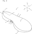
- the midsole 3 of this embodiment is formed of a plate-shaped foam having a larger thickness than the thickness of the outsole 4, and is arranged to have the thickness direction corresponding to the height direction Z of the shoe, as shown in Fig. 2 , Fig. 3 , and Fig. 4 .
- the midsole 3 has a lower surface 3b that is bonded to an upper surface of the outsole 4, an upper surface 3a that is bonded from below to the upper 2, and a lateral surface 3s that connects together the outer edges of the upper surface 3a and the lower surface 3b.
- the lateral surface 3s of the midsole 3 is formed to circulate around the outer periphery of the midsole 3 along the outer edges of the upper surface 3a and the lower surface 3b.
- the upper surface 3a is formed to extend inward from the upper end of the lateral surface 3s
- the lower surface 3b is formed to extend inward from the lower end of the lateral surface 3s.
- the outer peripheral surface of the shoe sole has the upper side constituted by the lateral surface 3s of the midsole 3, and has the lower side constituted by a lateral surface 4s of the outsole 4.
- the midsole 3 is composed of a foam as shown in Fig. 2 .
- the foam constituting the midsole 3 has a surface constituted by a non-foamed film 3d, as shown in Fig. 3 . That is, the foam is constituted by a surface portion that is a non-foamed region, and a portion inside the non-foamed region that includes cells 3f.
- the foam constituting the midsole 3 of this embodiment is an injection molded article as will be described in detail later, and includes a foamed region 3e and the film 3d covering the foamed region 3e that are both composed of the same polymer composition.
- At least a part of the film 3d covering the surface of the midsole 3 is a thick film having a thickness of 50 ⁇ m or more.
- the thick film is provided on the lateral surface 3s of the midsole 3. The thick film acts effectively to exhibit excellent stiffness when the midsole 3 is bent or twisted.
- the stiffness exhibited on the midsole 3 can be adjusted mainly by, for example, the thickness of the film 3d.
- the stiffness can be adjusted by devising the shape of the midsole 3 so that the film 3d has a corrugated shape.
- the stiffness can also be adjusted by considerably determining what degree of thickness of the film 3d is to be applied to which part of the midsole 3. That is, in this embodiment, the midsole can exhibit a desired stiffness without excessively reducing the expansion ratio of the foamed region or selecting a hard resin having a high elastic modulus as a base resin of the polymer composition constituting the foam.
- the midsole 3 can be constituted by a foam having both high stiffness and excellent shock absorbing properties.
- the expansion ratio of the foamed region 3e in the foam is preferably 2 times or more. In order to form the midsole 3 having high stiffness, the expansion ratio of the foamed region 3e in the foam is preferably 7 times or less, more preferably 6 times or less.
- the expansion ratio of the foamed region 3e can be determined by preparing a sample of the foam from which the film 3d is removed, and measuring the apparent density and the true density of the sample. The apparent density of the sample can be measured, for example, based on the method described in JIS K7222:2005 "Cellular plastics and rubbers - Determination of apparent
- the true density of the sample can be determined by, for example, hot-pressing the sample into a non-foamed product.
- the true density of the sample can be obtained by measuring the density of the non-foamed product by the method A (Underwater displacement) of JIS K7112:1999 "Plastics - Methods of determining the density and relative density of non-cellular plastics".
- the measurement of true density can also be determined by using the film 3d as a measurement sample in substitution for the non-foamed product made of the sample that has been hot-pressed.
- the foam in this embodiment includes a thick film having a thickness of 50 ⁇ m or more, as described above.
- the foam preferably includes a thick film having a thickness of 100 ⁇ m or more, more preferably includes a thick film having a thickness of 120 ⁇ m or more, particularly preferably includes a thick film having a thickness of 150 ⁇ m or more.
- the foam preferably has 50% or more in area of the lateral surface 3s constituted by the aforementioned thick film, more preferably has 70% or more constituted by the aforementioned thick film, particularly preferably has 90% or more constituted by the aforementioned thick film. It is preferable that the foam have not only the lateral surface 3s but also the upper surface 3a and the lower surface 3b each constituted by the aforementioned thick film at the above proportions.
- the foam preferably satisfies the following relational expressions (1) and (2) below: 0.8 ⁇ t 2 / t 1 ⁇ 1.25 50 ⁇ t 1 ⁇ 300
- the average thickness t 1 ( ⁇ m) of the thick film on the lateral surface 3s can be determined by dividing a cross-sectional area of the thick film by the length (represented by the sign L in Fig. 3 ) of the thick film.
- the cross-sectional area of the thick film is obtained by cutting the thick film along a plane orthogonal to the thick film and parallel to the height direction (Z) of the shoe 1.
- the average thickness t 2 ( ⁇ m) of the thick film on the lower surface 3b can also be determined in the same manner as in the average thickness t 1 ( ⁇ m) on the lateral surface 3s.
- the thickness of the thick film at a corner portion 3c at which the lateral surface 3s and the lower surface 3b cross each other is preferably larger than the average thickness t 1 ( ⁇ m) on the lateral surface 3s and the average thickness t 2 ( ⁇ m) on the lower surface 3b.
- the thick film that satisfies the relational expressions (1) and (2) may be arranged in any of the forefoot portion 11, the midfoot portion 12, and the hindfoot portion 13, of the shoe 1.
- the thick film that satisfies the relational expressions (1) and (2) is preferably arranged in at least one of the forefoot portion 11 and the midfoot portion 12, more preferably arranged in both of these portions.
- the thick film that satisfies the relational expressions (1) and (2) is preferably provided in an area of the lateral surface 3s accounting for 50% or more of the peripheral length of the lateral surface 3s, more preferably provided in an area accounting for 70% or more, particularly preferably provided in an area accounting for 90% or more.
- the foam of this embodiment has a rising portion 33 protruding upward in the outer peripheral portion of the foam to support a heel of a wearer of the shoe 1, and the rising portion 33 has an outer surface 33a on which the thick film is provided.
- the rising portion 33 of this embodiment has a plate-shaped structure standing upward and extending along the outer peripheral portion of the foam, and is arranged in the hindfoot portion 13 of the shoe 1. Further, the rising portion 33 of this embodiment is arranged to cover the heel from three sides namely: the medial side, the lateral side, and the rear side.
- the height of the rising portion 33 is preferably 5 mm or more.
- the rising portion 33 suppresses the heel of the wearer from moving out of the shoe sole to the medial side (Y1) or the lateral side (Y2). This configuration allows the shoe 1 in this embodiment to be better fitted to the foot of the wearer.
- the rising portion 33 of this embodiment functions similarly to the heel counter 53x provided in the conventional shoe 1x.
- the shoe 1 of this embodiment may include a heel counter in substitution for the rising portion 33, or may include both the rising portion 33 and the heel counter.
- the rising portion 33 may be arranged on the lateral side of the forefoot portion 11.
- the rising portion 33 is arranged to cover the fifth toe of the wearer from the lateral side, which can suppress the toe of the wearer from moving out of the shoe sole to the lateral side (Y2).
- the rising portion 33 in this case functions similarly to the stabilizer 52x provided in the conventional shoe 1x.
- the shoe 1 of this embodiment may include the stabilizer in substitution for the rising portion 33, or may include both the rising portion 33 and the stabilizer.
- the rising portion 33 may be arranged in an arch portion (i.e., the medial side of the midfoot portion 12).
- the rising portion 33 in this case functions similarly to the shank member 51x provided in the conventional shoe 1x.
- the shoe 1 of this embodiment may include the shank member in substitution for the rising portion 33, or may include both the rising portion 33 and the shank member.
- the rising portion 33 may be arranged in only one or more than one position of the aforementioned positions.
- the shoe 1 of this embodiment may include only one or more than one members of the reinforcing members such as the shank member, the stabilizer, and the heel counter. These reinforcing members can usually be formed of a polymer composition harder (i.e., having a larger durometer hardness value) than the midsole. In this embodiment in which the midsole causes the shoe sole to exhibit excellent stiffness, these reinforcing members may be smaller or thinner than the conventional members. Since the midsole causes the shoe sole to exhibit excellent stiffness, the reinforcing members of this embodiment need not be composed of a hard resin, and can be composed of a polymer film, a leather sheet, a fiber sheet, or the like. Thus, the shoe of this embodiment can be lighter in weight than the conventional shoe even when the reinforcing members are employed.
- the rising portion 33 in this embodiment has an inner surface 33b used for being bonded to the upper 2.
- the thickness of the film 3d on the inner surface 33b of the rising portion 33 is preferably smaller than the thickness of the film 3d on the outer surface 33a.
- the thickness of the film 3d on the inner surface 33b of the rising portion 33 is preferably less than 150 ⁇ m even in the thickest portion.
- the maximum thickness of the film 3d on the inner surface 33b is more preferably less than 100 pm, particularly preferably less than 50 ⁇ m.
- the film may be cut off in at least a part of the region on the inner surface 33b of the rising portion 33 to bring the region into the state where the cells of the foam are open. That is, a part or the whole of the inner surface 33b may be a cut surface formed by cutting the foam. For the same reason, a part of the upper surface 3a and/or the lower surface 3b may be the cut surface.
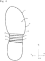
- the foam constituting the midsole 3 in this embodiment includes a rib 31 extending in the midfoot portion 12 along the width direction Y of the shoe 1 on the lower surface side, as shown in Fig. 4 .
- the rib 31 is covered by the thick film.
- the rib 31 acts effectively to cause the midsole 3 to exhibit excellent stiffness when the midsole 3 is twisted. This configuration enables the shoe 1 of this embodiment to obtain an excellent reinforcing effect without a shank member.
- the rib 31 of this embodiment is formed to cross the foam and rise in the both lateral surfaces 3s of the foam through the corner portions 3c.
- a plurality of ribs 31 are provided, and are arranged to be parallel to each other at intervals.
- a gap between each rib 31 and each adjacent rib 31 constitutes a groove 32 crossing the foam.
- a difference in height between the groove 32 and the rib 31 is preferably 1 mm or more, more preferably 2 mm or more.
- the difference in height is preferably 10 mm or less.
- a distance between each adjacent ribs 31 is preferably 20 mm or less, more preferably 15 mm or less. The distance is preferably 3mm or more.
- the midsole 3 of this embodiment having the ribs 31 and the grooves 32 has an uneven part in which recesses inward of the lateral surface 3s and projections outward thereof are alternately present in the length direction X of the shoe 1. That is, the midsole 3 of this embodiment has the uneven part formed by the rib(s) 31 and the groove(s) 32 that project and are recessed in the vertical direction Z. Moreover, in this embodiment, the uneven part is arranged on the medial side of the midfoot portion 12 of the shoe 1. This configuration allows the midsole 3 of this embodiment to exhibit high stiffness when the medial side of the midfoot portion 12 is subjected to compression force. Thus, the midsole 3 of this embodiment can prevent a leg of the wearer from falling inward.
- the uneven part is arranged also on the lateral side of the midfoot portion 12 of the shoe 1.
- This configuration enables the midsole 3 of this embodiment to prevent the leg of the wearer from falling on the lateral side and to effectively act on the wearer's stable walking.
- the uneven part is preferably formed to have a length of 10 mm or more, more preferably formed to have a length of 20 mm or more, in the length direction X of the shoe 1.
- the midsole 3 of this embodiment may have an uneven part in which recesses inward of the lateral surface 3s and projections outward thereof are alternately present in the thickness direction (vertical direction Z) of the midsole.
- the foam constituting the midsole 3 can be prepared by molding a polymer composition including a base polymer and a foaming agent using, for example, a molding die, in the course of which the film 3d can be formed.
- Examples of the base polymer of the polymer composition include olefin polymers such as polyethylene (e.g., linear low-density polyethylene (LLDPE) and high-density polyethylene (HDPE)), polypropylene, ethylenepropylene copolymer, propylene-1-hexene copolymer, propylene-4-methyl-1-pentene copolymer, propylene-1-butene copolymer, ethylene-1-hexene copolymer, ethylene-4-methyl-pentene copolymer, ethylene-1-butene copolymer, 1-butene-1-hexene copolymer, 1-butene-4-methyl-pentene, ethylene-methacrylate copolymer, ethylene-methyl methacrylate copolymer, ethylene-ethyl methacrylate copolymer, ethylene-butyl methacrylate copolymer, ethylene-methyl acrylate copolymer, ethylene-ethyl
- Examples of the base polymer include: polyamide-based resins such as polyamide 6, polyamide 11, polyamide 12, polyamide 66, and polyamide 610; and polyester-based resins such as polyethylene terephthalate and polybutylene terephthalate.
- the base polymer examples include a polyurethane-based polymer such as a polyester-based polyurethane or a polyether-based polyurethane; and a styrene-based polymer such as styrene-ethylene-butylene copolymer (SEB), styrene-butadiene-styrene copolymer (SBS), a hydrogenated product of SBS (styrene-ethylene-butylene-styrene copolymer (SEBS)), styreneisoprene-styrene copolymer (SIS), a hydrogenated product of SIS (styrene-ethylene-propylene-styrene copolymer (SEPS)), styrene-isobutylene-styrene copolymer (SIBS), styrene-butadiene-styrene-butadiene (SBSB), styrene-
- the base polymer may include a fluorine-based polymer such as fluororesin and fluororubber; a polyvinyl chloride-based resin; an acrylic resin such as polymethyl methacrylate; a silicone-based elastomer; butadiene rubber (BR); isoprene rubber (IR); chloroprene (CR); natural rubber (NR); styrene butadiene rubber (SBR); acrylonitrile butadiene rubber (NBR); or butyl rubber (IIR).
- a fluorine-based polymer such as fluororesin and fluororubber
- a polyvinyl chloride-based resin such as an acrylic resin such as polymethyl methacrylate
- BR butadiene rubber
- IR isoprene rubber
- CR chloroprene
- NR natural rubber
- SBR styrene butadiene rubber
- NBR acrylonitrile butadiene rubber
- IIR butyl rubber
- the polymer composition may include a crosslinking agent for crosslinking the base polymer as required.
- crosslinking agent an organic peroxide, a maleimid-based crosslinking agent, sulfur, a phenolic crosslinking agent, oximes, and polyamine, for example, can be employed. Further, crosslinking of the base polymer may be performed by irradiating an electron beam or an X-ray.
- organic peroxide examples include dicumyl peroxide, di-t-butyl peroxide, 2,5-dimethyl-2,5-di-(t-butylperoxy)hexane, 2,5-dimethyl-2,5-di-(t-butylperoxy)hexyne-3, 1,3-bis(t-butylperoxyisopropyl)benzene, 1,1-bis(t-butylperoxy)-3,3,5-trimethylcyclohexane, n-butyl-4,4-bis(t-butylperoxy)valerate, benzoyl peroxide, p-chlorobenzoyl peroxide, 2,4-dichlorobenzoyl peroxide, t-butylperoxybenzoate, t-butylperoxyisopropyl carbonate, diacetyl peroxide, lauroyl peroxide, and t-butylcumyl peroxide.
- the polymer composition may include a plurality of polymers and may include a plurality of crosslinking agents.
- the polymer composition may further include an inorganic filler such as clay, talc, silica, or carbon black.
- the foaming agent for causing the polymer composition to foam is not particularly limited, and examples thereof include an organic-based or inorganic-based chemical foaming agent and a physical foaming agent.
- an azo compound such as azodicarbonamide (ADCA), 1,1'-azobis(1-acetoxy-1-phenylethane), dimethyl-2,2'-azobisbutyrate, dimethyl-2,2'-azobisisobutyrate, 2,2'-azobis(2,4,4-trimethylpentane), 1,1'-azobis(cyclohexane-1-carbonitrile), or 2,2'-azobis[N-(2-carboxyethyl)-2-methyl-propionamidine]; a nitroso compound such as N,N'-dinitrosopentamethylenetetramine (DPT); a hydrazine derivative such as 4,4'-oxybis(benzenesulfonylhydrazide) or diphenylsulfone-3,3'-disulfonylhydrazide; a semicarbazide compound such as p-toluenesulfonyl semic
- ADCA azodicarbonamide
- thermally decomposable inorganic foaming agents such as bicarbonates, e.g., sodium hydrogen carbonate and ammonium hydrogen carbonate, and carbonates, e.g., sodium carbonate and ammonium carbonate; nitrites such as ammonium nitrite, and hydrogen compounds can be employed.
- an organic foaming agent such as various aliphatic hydrocarbons, e.g., methanol, ethanol, propane, butane, pentane, and hexane, or an inorganic foaming agent such as air, carbon dioxide, nitrogen, argon, and water can be used.
- the inorganic foaming agent is preferably used under such conditions as to be a supercritical fluid.
- the polymer composition may further include one or more selected from, for example, a processing aid, a weathering agent, a flame retardant, a pigment, a mold release agent, an antistatic agent, an antibacterial agent, and a deodorizer.
- a processing aid for example, a weathering agent, a flame retardant, a pigment, a mold release agent, an antistatic agent, an antibacterial agent, and a deodorizer.
- the method for forming the foam using the polymer composition is not particularly limited, but an injection molding method is preferably employed in terms of easily forming the film 3d into a desired state, and the core back method in which the heated and molten polymer composition is injected into a cavity of the forming mold, and thereafter the volumetric capacity of the cavity is increased to cause the polymer composition to foam is above all preferably employed.
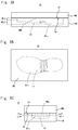
- a forming mold M as shown in Fig. 5A, Fig. 5B, and Fig. 5C is used.
- the forming mold M is composed of a pair of molds respectively having molding surfaces Sf and Sm that come into contact with each other when the forming mold M is closed.
- the forming mold M has a male mold MM and a female mold MF as the pair of molds.
- the forming mold M is configured to be able to form a tightly closed molding space CV inside thereof by joining the male mold MM and the female mold MF to each other.
- the forming mold M has an inlet IL through which the polymer composition molten and kneaded in an injection molding machine is introduced from the injection molding machine to the molding space CV.
- the forming mold M is configured to be able to form the molding space CV inside thereof when the mold is closed.
- the molding space CV has a shape in plan view the same as that of the foam, and has a shape in side view thinner than that of the foam.
- the forming mold M is formed so that a molding space CV' formed inside thereof in the state where a gap is formed between the molding surface Sm of the male mold MM and the molding surface Sf of the female mold MF has such a shape as to correspond to the shape of the foam.
- the forming mold M used in this embodiment is capable of switching between a first state in which the molding space CV having a smaller volumetric capacity than the foam to be prepared is formed inside the forming mold M and a second state in which the forming molding CV' having a larger volumetric capacity than that in the first state is formed inside the forming mold M.
- the female mold MF has a molding recess MFa that is open on a side having the molding surface Sf and recesses in a thickness direction of the female mold MF.
- the molding recess MFa is formed so that its depth direction corresponds to the thickness direction of the midsole 3.
- the male mold MM has a molding projection MMa that projects from the molding surface Sm and can project into the molding recess MFa of the female mold MF.
- the cross-sectional area of the molding recess MFa taken at a plane orthogonal to the direction in which the molding projection MMa projects varies in the depth direction. Specifically, the upper portion of the molding recess MFa has a smaller cross-sectional area than that in the lower portion.
- the forming recess MFa has a small-area region MFa1 having a smaller cross-sectional area in an upper portion in the depth direction than in the lower portion, and a large-area region MFa2 having a larger cross-sectional area in a portion below the small-area region MFa1 than the cross-sectional area of the small-area region MFa1.
- the cross-sectional area of the molding recess MFa in the small-area region MFa1 has a shape corresponding to the contour shape of the molding projection MMa.
- the cross-sectional area of the molding recess MFa in the large-area region MFa2 has a shape slightly larger than the contour shape of the molding projection MMa.
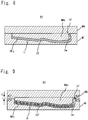
- the heated and molten polymer composition is injected into the molding space CV of the forming mold M that is held in the first state ( Fig. 8 ), and then causing the forming mold M to change into the second state ( Fig. 9 ).
- a distance D is provided between the female mold MF and the male mold MM so that the leading end of the molding projection MMa is located in the small-area region MMa1.
- a new molding space CV' having a larger volumetric capacity than the molding space CV in the first state is formed in the forming mold to thereby reduce the pressure of the polymer composition and cause the polymer composition to expand into a foam so as to fill the molding space CV'.
- the foam constituting the midsole 3 is thus prepared.
- the polymer composition that has been injected into the molding space CV is cooled by the leading surface of the molding projection MMa and the inner wall surface of the molding recess MFa; thus, the film 3d on the surface of the foam can have a large thickness by prolonging the period from the time when the polymer composition is injected into the molding space CV to the time when the molding space CV turns to the second state.
- the thickness of the film 3d can be adjusted also by the temperature conditions (cooling conditions) of the female mold MF and the male mold MM.
- the polymer composition be injected into the molding space CV under the conditions where the foaming agent is in a supercritical state.
- the foaming agent used at this time is preferably carbon dioxide, nitrogen, argon, or the like.
- the shoe sole member of the present invention is a shoe sole member composed of a foam.
- the foam in the present invention is composed of a polymer composition, the polymer composition has a surface composed of a non-foamed film at least partially having a thickness of 50 ⁇ m or more, the foam has a lateral surface constituting at least a part of an outer peripheral surface of a shoe sole, and the lateral surface includes the film.
- the shoe sole member of the present invention can exhibit stiffness and shock absorbing properties. This embodiment has been described by taking the midsole as an example of the shoe sole member, but the shoe sole member of the present invention is not limited to the midsole.
- the foam in the above exemplification is an injection molded article to thereby enable the thickness of the film to be easily adjustable, but the foam of the present invention is not limited to an injection molded article.
- the foam in the above exemplification includes a lower surface extending inward from a lower end of the lateral surface, includes the film continuously extending from the lateral surface to the lower surface, and satisfies the relational expressions (1) and (2) below to exhibit reasonable stiffness where an average thickness of the film on the lateral surface is t 1 ( ⁇ m) and an average thickness of the film on the lower surface is t 2 ( ⁇ m): 0.8 ⁇ t 2 / t 1 ⁇ 1.25 50 ⁇ t 1 ⁇ 300
- the film satisfying the relational expressions (1) and (2) is arranged in the forefoot portion of the shoe or in the midfoot portion to enable the provision of the shoe sole member excellent in stiffness and shock absorbing properties, but the present invention does not require the foam to satisfy the relational expressions (1) and (2).
- the shoe that can be easily fitted to the foot of the wearer by arranging the rising portion in the hindfoot portion has been exemplified above, but the shoe sole member of the present invention does not have to include the rising portion. That is, the shoe sole member of the present invention and the shoe of the present invention are not limited to the aforementioned exemplification at all.
Landscapes
- Engineering & Computer Science (AREA)
- Chemical & Material Sciences (AREA)
- Materials Engineering (AREA)
- Mechanical Engineering (AREA)
- Footwear And Its Accessory, Manufacturing Method And Apparatuses (AREA)
Abstract
Description
- The present invention relates to a shoe sole member and a shoe, more specifically, to a shoe sole member used as, for example, a midsole or an outsole, and a shoe including such a shoe sole member.
- Shoes used for various competitions conventionally include
uppers 2x and shoe soles, as shown inFig. 10 . Theshoes 1x are composed of a number of parts. For example, theshoe 1x is composed of shoe sole members such as an inner sole (not shown), a sock liner (not shown), amidsole 3x, and anoutsole 4x. Conventionally, the shoe sole members of this type have been demanded to be excellent in lightweight properties and shock absorbing properties. Therefore, many of the shoe sole members are composed of a foam obtained by foaming a polymer composition including, as a main component, a polymer such as rubber or a plastic. In this regard,Patent Literature 1 below describes that a member called a shank member is used in addition to a midsole composed of a foam in order to improve characteristics such as shock absorbing properties.Patent Literature 1 below further describes that the shank member is formed of a resin that is harder and more elastic than the resin used to form the midsole, to cause the shoe sole to exhibit reasonable stiffness. As shown in the figure, ashank member 51x formed of a hard resin is usually arranged in a midfoot portion to rise from an outer peripheral portion of the shoe sole to function as a reinforcing member for firmly holding a foot. Known examples of the reinforcing member of this type include a member called astabilizer 52x arranged in a forefoot portion, and a member called aheel counter 53x arranged in a hindfoot portion. - Patent Literature 1:
JP 2010-246785 A - The shoe sole including a shoe sole member composed of a foam with an improved stiffness against bending or torsion as compared with a conventional foam can fulfill a function similar to that fulfilled when a reinforcing member such as a shank member is used. That is, provision of such a foam not only enables the reinforcing member to reduce its size and thickness to thereby obtain lightweight shoes, but also enables the use of special members such as the reinforcing member to be omitted in some cases. A possible way to improve the stiffness of the foam can be to select a hard resin as a forming material of the foam, or to reduce the expansion ratio of the foam. However, in such cases, the stiffness against bending and torsion can be improved, but there is a possibility of impairing the characteristics such as lightweight properties and shock absorbing properties. It has been thus difficult to obtain a shoe sole member composed of a foam having both stiffness and shock absorbing properties. It is therefore an object of the present invention to provide such a shoe sole member, and further to provide a shoe excellent in shock absorbing properties.
- In order to solve the above problem, the present invention provides a shoe sole member composed of a foam, the foam composed of a polymer composition and having a surface composed of a non-foamed film at least partially having a thickness of 50 µm or more, the foam having a lateral surface constituting at least a part of an outer peripheral surface of the shoe sole, and the lateral surface including the film.
- Further, in order to solve the above problem, the present invention provides a shoe including the shoe sole member as aforementioned.
-
-
Fig. 1 is a schematic perspective view showing a shoe including shoe sole members. -
Fig. 2 is a perspective view of a shoe sole member according to one embodiment. -
Fig. 3 is a cross-sectional view as viewed in the direction of arrows of III-III inFig. 2 . -
Fig. 4 is a bottom view of the shoe sole member according to the one embodiment. -
Fig. 5A is a schematic front view of a forming mold for making the shoe sole member of the one embodiment. -
Fig. 5B is a schematic plan view of the forming mold for making the shoe sole member of the one embodiment. -
Fig. 5C is a schematic side view of the forming mold for making the shoe sole member of the one embodiment. -
Fig. 6 is a cross-sectional view as viewed in the direction of arrows of VI-VI inFig. 5C . -
Fig. 7 is a cross-sectional view as viewed in the direction of arrows of VII-VII inFig. 5C . -
Fig. 8 is a schematic view showing a method for molding the shoe sole member using the forming mold shown inFig. 5 (first state). -
Fig. 9 is a schematic view showing the method for molding the shoe sole member using the forming mold shown inFig. 5 (second state). -
Fig. 10 is a schematic perspective view showing conventional shoes including reinforcing members. - A shoe sole member of the present invention will be described below by showing an embodiment thereof. A description will be hereinafter given by taking a midsole as an example of the shoe sole member of the present invention.
Fig. 1 shows a shoe formed using shoe sole members of this embodiment. Theshoe 1 includes an upper 2 and a shoe sole. The shoe sole is composed of a plurality of shoe sole members. Theshoe 1 includes amidsole 3 and anoutsole 4 as the shoe sole members. Hereinafter, when a description is given on theshoe 1 shown inFig. 1 , a direction along a shoe center axis CX connecting a heel center HC and a toe center TC may be referred to as a length direction X. Among directions along the shoe center axis CX, a direction X1 directed from the heel to the toe may be referred to as, for example, a forward direction, and a direction X2 directed from the toe to the heel may be referred to as, for example, a rearward direction. Further, among directions orthogonal to the shoe center axis CX, a direction parallel to a horizontal plane HP may be referred to as a width direction Y. Regarding the width direction Y, a direction Y1 directed to the first toe side may be referred to as, for example, a medial side direction, and a direction Y2 directed to the fifth toe side may be referred to as, for example, a lateral side direction. A vertical direction Z orthogonal to the horizontal plane HP may be referred to as a thickness direction or a height direction. Further, hereinafter, a direction Z1 directed upward in this vertical direction Z may be referred to as an upward direction, and a direction Z2 directed downward may be referred to as a downward direction. - As shown in
Fig. 1 , theshoe 1 of this embodiment includes theoutsole 4 in its bottommost position. Theoutsole 4 of this embodiment has a sheet shape, and is arranged in the lowermost part of theshoe 1 to have the thickness direction corresponding to the vertical direction Z. Theshoe 1 includes themidsole 3 between theoutsole 4 and the upper 2 that covers a foot of a wearer from the upper side. Themidsole 3 of this embodiment is formed of a plate-shaped foam having a larger thickness than the thickness of theoutsole 4, and is arranged to have the thickness direction corresponding to the height direction Z of the shoe, as shown inFig. 2 ,Fig. 3 , andFig. 4 . Themidsole 3 has alower surface 3b that is bonded to an upper surface of theoutsole 4, anupper surface 3a that is bonded from below to the upper 2, and alateral surface 3s that connects together the outer edges of theupper surface 3a and thelower surface 3b. Thelateral surface 3s of themidsole 3 is formed to circulate around the outer periphery of themidsole 3 along the outer edges of theupper surface 3a and thelower surface 3b. In other words, theupper surface 3a is formed to extend inward from the upper end of thelateral surface 3s, and thelower surface 3b is formed to extend inward from the lower end of thelateral surface 3s. - The entire
lateral surface 3s except a part of the toe portion of themidsole 3 is exposed on the outer peripheral surface of the shoe sole. That is, the outer peripheral surface of the shoe sole has the upper side constituted by thelateral surface 3s of themidsole 3, and has the lower side constituted by alateral surface 4s of theoutsole 4. - The
midsole 3 is composed of a foam as shown inFig. 2 . The foam constituting themidsole 3 has a surface constituted by anon-foamed film 3d, as shown inFig. 3 . That is, the foam is constituted by a surface portion that is a non-foamed region, and a portion inside the non-foamed region that includescells 3f. The foam constituting themidsole 3 of this embodiment is an injection molded article as will be described in detail later, and includes a foamedregion 3e and thefilm 3d covering the foamedregion 3e that are both composed of the same polymer composition. - In this embodiment, at least a part of the
film 3d covering the surface of themidsole 3 is a thick film having a thickness of 50 µm or more. The thick film is provided on thelateral surface 3s of themidsole 3. The thick film acts effectively to exhibit excellent stiffness when themidsole 3 is bent or twisted. - The stiffness exhibited on the
midsole 3 can be adjusted mainly by, for example, the thickness of thefilm 3d. The stiffness can be adjusted by devising the shape of themidsole 3 so that thefilm 3d has a corrugated shape. The stiffness can also be adjusted by considerably determining what degree of thickness of thefilm 3d is to be applied to which part of themidsole 3. That is, in this embodiment, the midsole can exhibit a desired stiffness without excessively reducing the expansion ratio of the foamed region or selecting a hard resin having a high elastic modulus as a base resin of the polymer composition constituting the foam. Thus, in this embodiment, themidsole 3 can be constituted by a foam having both high stiffness and excellent shock absorbing properties. - In order to form the
midsole 3 having excellent shock absorbing properties, the expansion ratio of the foamedregion 3e in the foam is preferably 2 times or more. In order to form themidsole 3 having high stiffness, the expansion ratio of the foamedregion 3e in the foam is preferably 7 times or less, more preferably 6 times or less. The expansion ratio of the foamedregion 3e can be determined by preparing a sample of the foam from which thefilm 3d is removed, and measuring the apparent density and the true density of the sample. The apparent density of the sample can be measured, for example, based on the method described in JIS K7222:2005 "Cellular plastics and rubbers - Determination of apparent - (bulk) density". The true density of the sample can be determined by, for example, hot-pressing the sample into a non-foamed product. The true density of the sample can be obtained by measuring the density of the non-foamed product by the method A (Underwater displacement) of JIS K7112:1999 "Plastics - Methods of determining the density and relative density of non-cellular plastics". The measurement of true density can also be determined by using the
film 3d as a measurement sample in substitution for the non-foamed product made of the sample that has been hot-pressed. The expansion ratio can be determined by the formula below:
- The foam in this embodiment includes a thick film having a thickness of 50 µm or more, as described above. In order to form the
midsole 3 having both high stiffness and excellent shock absorbing properties, the foam preferably includes a thick film having a thickness of 100 µm or more, more preferably includes a thick film having a thickness of 120 µm or more, particularly preferably includes a thick film having a thickness of 150 µm or more. The foam preferably has 50% or more in area of thelateral surface 3s constituted by the aforementioned thick film, more preferably has 70% or more constituted by the aforementioned thick film, particularly preferably has 90% or more constituted by the aforementioned thick film. It is preferable that the foam have not only thelateral surface 3s but also theupper surface 3a and thelower surface 3b each constituted by the aforementioned thick film at the above proportions. - It is preferable that at least a part of the aforementioned thick film continuously extend from the
lateral surface 3s to thelower surface 3b. It is more preferable that the thick film continuously extending from thelateral surface 3s to thelower surface 3b continuously extend to theupper surface 3a. Where the average thickness of the thick film on thelateral surface 3s is t1 (µm) and the average thickness of the film on thelower surface 3b is t2 (µm), the foam preferably satisfies the following relational expressions (1) and (2) below:

- The average thickness t1 (µm) of the thick film on the
lateral surface 3s can be determined by dividing a cross-sectional area of the thick film by the length (represented by the sign L inFig. 3 ) of the thick film. The cross-sectional area of the thick film is obtained by cutting the thick film along a plane orthogonal to the thick film and parallel to the height direction (Z) of theshoe 1. The average thickness t2 (µm) of the thick film on thelower surface 3b can also be determined in the same manner as in the average thickness t1 (µm) on thelateral surface 3s. The thickness of the thick film at acorner portion 3c at which thelateral surface 3s and thelower surface 3b cross each other is preferably larger than the average thickness t1 (µm) on thelateral surface 3s and the average thickness t2 (µm) on thelower surface 3b. - The thick film that satisfies the relational expressions (1) and (2) may be arranged in any of the
forefoot portion 11, themidfoot portion 12, and thehindfoot portion 13, of theshoe 1. The thick film that satisfies the relational expressions (1) and (2) is preferably arranged in at least one of theforefoot portion 11 and themidfoot portion 12, more preferably arranged in both of these portions. The thick film that satisfies the relational expressions (1) and (2) is preferably provided in an area of thelateral surface 3s accounting for 50% or more of the peripheral length of thelateral surface 3s, more preferably provided in an area accounting for 70% or more, particularly preferably provided in an area accounting for 90% or more. - The foam of this embodiment has a rising
portion 33 protruding upward in the outer peripheral portion of the foam to support a heel of a wearer of theshoe 1, and the risingportion 33 has anouter surface 33a on which the thick film is provided. The risingportion 33 of this embodiment has a plate-shaped structure standing upward and extending along the outer peripheral portion of the foam, and is arranged in thehindfoot portion 13 of theshoe 1. Further, the risingportion 33 of this embodiment is arranged to cover the heel from three sides namely: the medial side, the lateral side, and the rear side. The height of the risingportion 33 is preferably 5 mm or more. - The rising
portion 33 suppresses the heel of the wearer from moving out of the shoe sole to the medial side (Y1) or the lateral side (Y2). This configuration allows theshoe 1 in this embodiment to be better fitted to the foot of the wearer. The risingportion 33 of this embodiment functions similarly to theheel counter 53x provided in theconventional shoe 1x. Theshoe 1 of this embodiment may include a heel counter in substitution for the risingportion 33, or may include both the risingportion 33 and the heel counter. - The rising
portion 33 may be arranged on the lateral side of theforefoot portion 11. In this case, the risingportion 33 is arranged to cover the fifth toe of the wearer from the lateral side, which can suppress the toe of the wearer from moving out of the shoe sole to the lateral side (Y2). The risingportion 33 in this case functions similarly to thestabilizer 52x provided in theconventional shoe 1x. Theshoe 1 of this embodiment may include the stabilizer in substitution for the risingportion 33, or may include both the risingportion 33 and the stabilizer. - The rising
portion 33 may be arranged in an arch portion (i.e., the medial side of the midfoot portion 12). The risingportion 33 in this case functions similarly to theshank member 51x provided in theconventional shoe 1x. Theshoe 1 of this embodiment may include the shank member in substitution for the risingportion 33, or may include both the risingportion 33 and the shank member. - The rising
portion 33 may be arranged in only one or more than one position of the aforementioned positions. Theshoe 1 of this embodiment may include only one or more than one members of the reinforcing members such as the shank member, the stabilizer, and the heel counter. These reinforcing members can usually be formed of a polymer composition harder (i.e., having a larger durometer hardness value) than the midsole. In this embodiment in which the midsole causes the shoe sole to exhibit excellent stiffness, these reinforcing members may be smaller or thinner than the conventional members. Since the midsole causes the shoe sole to exhibit excellent stiffness, the reinforcing members of this embodiment need not be composed of a hard resin, and can be composed of a polymer film, a leather sheet, a fiber sheet, or the like. Thus, the shoe of this embodiment can be lighter in weight than the conventional shoe even when the reinforcing members are employed. - The rising
portion 33 in this embodiment has aninner surface 33b used for being bonded to the upper 2. In order to exhibit the excellent capability for following the deformation of the upper 2, the thickness of thefilm 3d on theinner surface 33b of the risingportion 33 is preferably smaller than the thickness of thefilm 3d on theouter surface 33a. The thickness of thefilm 3d on theinner surface 33b of the risingportion 33 is preferably less than 150 µm even in the thickest portion. The maximum thickness of thefilm 3d on theinner surface 33b is more preferably less than 100 pm, particularly preferably less than 50 µm. In order to exhibit the excellent anchor effect to the bond, the film may be cut off in at least a part of the region on theinner surface 33b of the risingportion 33 to bring the region into the state where the cells of the foam are open. That is, a part or the whole of theinner surface 33b may be a cut surface formed by cutting the foam. For the same reason, a part of theupper surface 3a and/or thelower surface 3b may be the cut surface. - The foam constituting the
midsole 3 in this embodiment includes arib 31 extending in themidfoot portion 12 along the width direction Y of theshoe 1 on the lower surface side, as shown inFig. 4 . In the foam of this embodiment, therib 31 is covered by the thick film. Therib 31 acts effectively to cause themidsole 3 to exhibit excellent stiffness when themidsole 3 is twisted. This configuration enables theshoe 1 of this embodiment to obtain an excellent reinforcing effect without a shank member. Therib 31 of this embodiment is formed to cross the foam and rise in the bothlateral surfaces 3s of the foam through thecorner portions 3c. In this embodiment, a plurality ofribs 31 are provided, and are arranged to be parallel to each other at intervals. A gap between eachrib 31 and eachadjacent rib 31 constitutes agroove 32 crossing the foam. In order to cause thegroove 32 and therib 31 to more remarkably exhibit the reinforcing effect, a difference in height between thegroove 32 and therib 31 is preferably 1 mm or more, more preferably 2 mm or more. The difference in height is preferably 10 mm or less. A distance between eachadjacent ribs 31 is preferably 20 mm or less, more preferably 15 mm or less. The distance is preferably 3mm or more. - The
midsole 3 of this embodiment having theribs 31 and thegrooves 32 has an uneven part in which recesses inward of thelateral surface 3s and projections outward thereof are alternately present in the length direction X of theshoe 1. That is, themidsole 3 of this embodiment has the uneven part formed by the rib(s) 31 and the groove(s) 32 that project and are recessed in the vertical direction Z. Moreover, in this embodiment, the uneven part is arranged on the medial side of themidfoot portion 12 of theshoe 1. This configuration allows themidsole 3 of this embodiment to exhibit high stiffness when the medial side of themidfoot portion 12 is subjected to compression force. Thus, themidsole 3 of this embodiment can prevent a leg of the wearer from falling inward. - In the
midsole 3 of this embodiment, the uneven part is arranged also on the lateral side of themidfoot portion 12 of theshoe 1. This configuration enables themidsole 3 of this embodiment to prevent the leg of the wearer from falling on the lateral side and to effectively act on the wearer's stable walking. The uneven part is preferably formed to have a length of 10 mm or more, more preferably formed to have a length of 20 mm or more, in the length direction X of theshoe 1. Themidsole 3 of this embodiment may have an uneven part in which recesses inward of thelateral surface 3s and projections outward thereof are alternately present in the thickness direction (vertical direction Z) of the midsole. - The foam constituting the
midsole 3 can be prepared by molding a polymer composition including a base polymer and a foaming agent using, for example, a molding die, in the course of which thefilm 3d can be formed. - Examples of the base polymer of the polymer composition include olefin polymers such as polyethylene (e.g., linear low-density polyethylene (LLDPE) and high-density polyethylene (HDPE)), polypropylene, ethylenepropylene copolymer, propylene-1-hexene copolymer, propylene-4-methyl-1-pentene copolymer, propylene-1-butene copolymer, ethylene-1-hexene copolymer, ethylene-4-methyl-pentene copolymer, ethylene-1-butene copolymer, 1-butene-1-hexene copolymer, 1-butene-4-methyl-pentene, ethylene-methacrylate copolymer, ethylene-methyl methacrylate copolymer, ethylene-ethyl methacrylate copolymer, ethylene-butyl methacrylate copolymer, ethylene-methyl acrylate copolymer, ethylene-ethyl acrylate copolymer, ethylene-butyl acrylate copolymer, propylene-methacrylate copolymer, propylene-methyl methacrylate copolymer, propylene-ethyl methacrylate copolymer, propylene-butyl methacrylate copolymer, propylene-methyl acrylate copolymer, propylene-ethyl acrylate copolymer, propylene-butyl acrylate copolymer, ethylene-vinyl acetate copolymer (EVA), and propylene-vinyl acetate copolymer.
- Examples of the base polymer include: polyamide-based resins such as polyamide 6,
polyamide 11,polyamide 12, polyamide 66, and polyamide 610; and polyester-based resins such as polyethylene terephthalate and polybutylene terephthalate. - Examples of the base polymer include a polyurethane-based polymer such as a polyester-based polyurethane or a polyether-based polyurethane; and a styrene-based polymer such as styrene-ethylene-butylene copolymer (SEB), styrene-butadiene-styrene copolymer (SBS), a hydrogenated product of SBS (styrene-ethylene-butylene-styrene copolymer (SEBS)), styreneisoprene-styrene copolymer (SIS), a hydrogenated product of SIS (styrene-ethylene-propylene-styrene copolymer (SEPS)), styrene-isobutylene-styrene copolymer (SIBS), styrene-butadiene-styrene-butadiene (SBSB), styrene-butadiene-styrene-butadiene-styrene (SBSBS), polystyrene, acrylonitrile styrene resin (AS resin), or acrylonitrile butadiene styrene resin (ABS resin).
- Examples of the base polymer may include a fluorine-based polymer such as fluororesin and fluororubber; a polyvinyl chloride-based resin; an acrylic resin such as polymethyl methacrylate; a silicone-based elastomer; butadiene rubber (BR); isoprene rubber (IR); chloroprene (CR); natural rubber (NR); styrene butadiene rubber (SBR); acrylonitrile butadiene rubber (NBR); or butyl rubber (IIR).
- The polymer composition may include a crosslinking agent for crosslinking the base polymer as required.
- As the crosslinking agent, an organic peroxide, a maleimid-based crosslinking agent, sulfur, a phenolic crosslinking agent, oximes, and polyamine, for example, can be employed. Further, crosslinking of the base polymer may be performed by irradiating an electron beam or an X-ray.
- Examples of the organic peroxide include dicumyl peroxide, di-t-butyl peroxide, 2,5-dimethyl-2,5-di-(t-butylperoxy)hexane, 2,5-dimethyl-2,5-di-(t-butylperoxy)hexyne-3, 1,3-bis(t-butylperoxyisopropyl)benzene, 1,1-bis(t-butylperoxy)-3,3,5-trimethylcyclohexane, n-butyl-4,4-bis(t-butylperoxy)valerate, benzoyl peroxide, p-chlorobenzoyl peroxide, 2,4-dichlorobenzoyl peroxide, t-butylperoxybenzoate, t-butylperoxyisopropyl carbonate, diacetyl peroxide, lauroyl peroxide, and t-butylcumyl peroxide.
- The polymer composition may include a plurality of polymers and may include a plurality of crosslinking agents. The polymer composition may further include an inorganic filler such as clay, talc, silica, or carbon black. The foaming agent for causing the polymer composition to foam is not particularly limited, and examples thereof include an organic-based or inorganic-based chemical foaming agent and a physical foaming agent. As the foaming agent, one or more selected from: an azo compound such as azodicarbonamide (ADCA), 1,1'-azobis(1-acetoxy-1-phenylethane), dimethyl-2,2'-azobisbutyrate, dimethyl-2,2'-azobisisobutyrate, 2,2'-azobis(2,4,4-trimethylpentane), 1,1'-azobis(cyclohexane-1-carbonitrile), or 2,2'-azobis[N-(2-carboxyethyl)-2-methyl-propionamidine]; a nitroso compound such as N,N'-dinitrosopentamethylenetetramine (DPT); a hydrazine derivative such as 4,4'-oxybis(benzenesulfonylhydrazide) or diphenylsulfone-3,3'-disulfonylhydrazide; a semicarbazide compound such as p-toluenesulfonyl semicarbazide; and an organic heat decomposable foaming agent such as trihydrazinotriazine can be employed.
- As the foaming agent, one or more selected from thermally decomposable inorganic foaming agents such as bicarbonates, e.g., sodium hydrogen carbonate and ammonium hydrogen carbonate, and carbonates, e.g., sodium carbonate and ammonium carbonate; nitrites such as ammonium nitrite, and hydrogen compounds can be employed.
- As the foaming agent, an organic foaming agent such as various aliphatic hydrocarbons, e.g., methanol, ethanol, propane, butane, pentane, and hexane, or an inorganic foaming agent such as air, carbon dioxide, nitrogen, argon, and water can be used. The inorganic foaming agent is preferably used under such conditions as to be a supercritical fluid.
- The polymer composition may further include one or more selected from, for example, a processing aid, a weathering agent, a flame retardant, a pigment, a mold release agent, an antistatic agent, an antibacterial agent, and a deodorizer.
- The method for forming the foam using the polymer composition is not particularly limited, but an injection molding method is preferably employed in terms of easily forming the
film 3d into a desired state, and the core back method in which the heated and molten polymer composition is injected into a cavity of the forming mold, and thereafter the volumetric capacity of the cavity is increased to cause the polymer composition to foam is above all preferably employed. - In order to prepare the foam constituting the
midsole 3 by the core back injection molding, for example a forming mold M as shown inFig. 5A, Fig. 5B, and Fig. 5C is used. As shown in the figures, the forming mold M is composed of a pair of molds respectively having molding surfaces Sf and Sm that come into contact with each other when the forming mold M is closed. The forming mold M has a male mold MM and a female mold MF as the pair of molds. The forming mold M is configured to be able to form a tightly closed molding space CV inside thereof by joining the male mold MM and the female mold MF to each other. The forming mold M has an inlet IL through which the polymer composition molten and kneaded in an injection molding machine is introduced from the injection molding machine to the molding space CV. - The forming mold M is configured to be able to form the molding space CV inside thereof when the mold is closed. The molding space CV has a shape in plan view the same as that of the foam, and has a shape in side view thinner than that of the foam. The forming mold M is formed so that a molding space CV' formed inside thereof in the state where a gap is formed between the molding surface Sm of the male mold MM and the molding surface Sf of the female mold MF has such a shape as to correspond to the shape of the foam. That is, the forming mold M used in this embodiment is capable of switching between a first state in which the molding space CV having a smaller volumetric capacity than the foam to be prepared is formed inside the forming mold M and a second state in which the forming molding CV' having a larger volumetric capacity than that in the first state is formed inside the forming mold M.
- The female mold MF has a molding recess MFa that is open on a side having the molding surface Sf and recesses in a thickness direction of the female mold MF. The molding recess MFa is formed so that its depth direction corresponds to the thickness direction of the
midsole 3. The male mold MM has a molding projection MMa that projects from the molding surface Sm and can project into the molding recess MFa of the female mold MF. The cross-sectional area of the molding recess MFa taken at a plane orthogonal to the direction in which the molding projection MMa projects varies in the depth direction. Specifically, the upper portion of the molding recess MFa has a smaller cross-sectional area than that in the lower portion. That is, the forming recess MFa has a small-area region MFa1 having a smaller cross-sectional area in an upper portion in the depth direction than in the lower portion, and a large-area region MFa2 having a larger cross-sectional area in a portion below the small-area region MFa1 than the cross-sectional area of the small-area region MFa1. The cross-sectional area of the molding recess MFa in the small-area region MFa1 has a shape corresponding to the contour shape of the molding projection MMa. The cross-sectional area of the molding recess MFa in the large-area region MFa2 has a shape slightly larger than the contour shape of the molding projection MMa. Thus, when the female mold MF and the male mold MM are joined to each other, the outer peripheral surface of the molding projection MMa and the inner wall surface of the molding recess MFa are held in contact with each other in the small-area region MFa1, as shown inFig. 6 , while a clearance CL is formed therebetween in the large-area region MFa2, as shown inFig. 7 . - To prepare the foam constituting the
midsole 3 by the core back injection molding, the heated and molten polymer composition is injected into the molding space CV of the forming mold M that is held in the first state (Fig. 8 ), and then causing the forming mold M to change into the second state (Fig. 9 ). At this time, a distance D is provided between the female mold MF and the male mold MM so that the leading end of the molding projection MMa is located in the small-area region MMa1. Then, a new molding space CV' having a larger volumetric capacity than the molding space CV in the first state is formed in the forming mold to thereby reduce the pressure of the polymer composition and cause the polymer composition to expand into a foam so as to fill the molding space CV'. The foam constituting themidsole 3 is thus prepared. - The polymer composition that has been injected into the molding space CV is cooled by the leading surface of the molding projection MMa and the inner wall surface of the molding recess MFa; thus, the
film 3d on the surface of the foam can have a large thickness by prolonging the period from the time when the polymer composition is injected into the molding space CV to the time when the molding space CV turns to the second state. The thickness of thefilm 3d can be adjusted also by the temperature conditions (cooling conditions) of the female mold MF and the male mold MM. In order to bring the foamedregion 3e formed inside thefilm 3d into a favorably foamed state at this time, it is preferable that the polymer composition be injected into the molding space CV under the conditions where the foaming agent is in a supercritical state. The foaming agent used at this time is preferably carbon dioxide, nitrogen, argon, or the like. - As described above, the shoe sole member of the present invention is a shoe sole member composed of a foam. The foam in the present invention is composed of a polymer composition, the polymer composition has a surface composed of a non-foamed film at least partially having a thickness of 50 µm or more, the foam has a lateral surface constituting at least a part of an outer peripheral surface of a shoe sole, and the lateral surface includes the film. Thus, the shoe sole member of the present invention can exhibit stiffness and shock absorbing properties. This embodiment has been described by taking the midsole as an example of the shoe sole member, but the shoe sole member of the present invention is not limited to the midsole.
- The foam in the above exemplification is an injection molded article to thereby enable the thickness of the film to be easily adjustable, but the foam of the present invention is not limited to an injection molded article.
- The foam in the above exemplification includes a lower surface extending inward from a lower end of the lateral surface, includes the film continuously extending from the lateral surface to the lower surface, and satisfies the relational expressions (1) and (2) below to exhibit reasonable stiffness where an average thickness of the film on the lateral surface is t1 (µm) and an average thickness of the film on the lower surface is t2 (µm):


- Further, in the exemplification above, the film satisfying the relational expressions (1) and (2) is arranged in the forefoot portion of the shoe or in the midfoot portion to enable the provision of the shoe sole member excellent in stiffness and shock absorbing properties, but the present invention does not require the foam to satisfy the relational expressions (1) and (2).
- Further, the shoe that can be easily fitted to the foot of the wearer by arranging the rising portion in the hindfoot portion has been exemplified above, but the shoe sole member of the present invention does not have to include the rising portion. That is, the shoe sole member of the present invention and the shoe of the present invention are not limited to the aforementioned exemplification at all.
-
- 1: Shoe
- 2: Upper
- 3: Midsole
- 3d: Film
- 3e: Foamed region
- 3s: Lateral surface
- 4: Outsole
- 11: Forefoot portion
- 12: Midfoot portion
- 13: Hindfoot portion
- 33: Rising portion
Claims (8)
- A shoe sole member composed of a foam,
the foam composed of a polymer composition and having a surface composed of a non-foamed film at least partially having a thickness of 50 µm or more,
the foam having a lateral surface constituting at least a part of an outer peripheral surface of the shoe sole, and
the lateral surface comprising the film. - The shoe sole member according to claim 1, wherein the foam is an injection molded article.
- The shoe sole member according to claim 1 or 2, wherein
the foam comprises a lower surface extending inward from a lower end of the lateral surface, comprises the film continuously extending from the lateral surface to the lower surface, and satisfies relational expressions (1) and (2) below where an average thickness of the film on the lateral surface is t1 (µm) and an average thickness of the film on the lower surface is t2 (µm):

- The shoe sole member according to claim 3, wherein the film satisfying the relational expressions (1) and (2) is arranged in a forefoot portion of a shoe.
- The shoe sole member according to claim 3, wherein the film satisfying the relational expressions (1) and (2) is arranged in a midfoot portion of a shoe.
- The shoe sole member according to any one of claims 1 to 5, wherein the foam has a rising portion projecting upward in an outer peripheral portion of the foam, and
the rising portion has an outer surface on which the film is provided. - The shoe sole member according to claim 6, wherein the rising portion is arranged in a hindfoot portion of a shoe.
- A shoe comprising the shoe sole member according to any one of claims 1 to 7.
Applications Claiming Priority (1)
| Application Number | Priority Date | Filing Date | Title |
|---|---|---|---|
| PCT/JP2018/032160 WO2020044506A1 (en) | 2018-08-30 | 2018-08-30 | Shoe sole member and shoe |
Publications (3)
| Publication Number | Publication Date |
|---|---|
| EP3827688A1 true EP3827688A1 (en) | 2021-06-02 |
| EP3827688A4 EP3827688A4 (en) | 2021-07-21 |
| EP3827688B1 EP3827688B1 (en) | 2025-07-02 |
Family
ID=69643553
Family Applications (1)
| Application Number | Title | Priority Date | Filing Date |
|---|---|---|---|
| EP18932021.1A Active EP3827688B1 (en) | 2018-08-30 | 2018-08-30 | Shoe sole member and shoe |
Country Status (6)
| Country | Link |
|---|---|
| US (1) | US11889888B2 (en) |
| EP (1) | EP3827688B1 (en) |
| JP (1) | JP6963694B2 (en) |
| CN (1) | CN112601472B (en) |
| AU (1) | AU2018438546A1 (en) |
| WO (1) | WO2020044506A1 (en) |
Families Citing this family (4)
| Publication number | Priority date | Publication date | Assignee | Title |
|---|---|---|---|---|
| US12426672B2 (en) * | 2019-08-30 | 2025-09-30 | Lululemon Athletica Canada Inc. | Segmented sole for footwear |
| USD1073277S1 (en) * | 2021-03-04 | 2025-05-06 | Hui Jiang | Air cushion outsole |
| USD968061S1 (en) * | 2021-05-13 | 2022-11-01 | Quanzhou Yuzhen Clothing Trading Co., Ltd. | Shoe sole |
| EP4494510A1 (en) * | 2023-07-19 | 2025-01-22 | Plastimedia S.r.l. | Method for making an insole of sports footwear, method for making sports footwear, insole and sports footwear |
Family Cites Families (34)
| Publication number | Priority date | Publication date | Assignee | Title |
|---|---|---|---|---|
| US2259687A (en) * | 1940-05-10 | 1941-10-21 | Fisch Arthur | Process for making orthopedic footwear |
| US2744340A (en) * | 1953-04-17 | 1956-05-08 | Gerber Plastic Company | Footwear and methods of making the same |
| GB1339646A (en) * | 1970-10-19 | 1973-12-05 | Fukuoka T | Shoes |
| JPS55163806U (en) * | 1979-05-10 | 1980-11-25 | ||
| JPS6141402A (en) * | 1984-08-02 | 1986-02-27 | 西田 成夫 | Synthetic resin footwear and its production |
| US7107706B1 (en) * | 1997-08-14 | 2006-09-19 | Promdx Technology, Inc. | Ergonomic systems and methods providing intelligent adaptive surfaces and temperature control |
| WO2003071892A1 (en) * | 2002-02-27 | 2003-09-04 | Midori Anzen Co., Ltd. | Sole and method of manufacturing the sole |
| JP2003245103A (en) * | 2002-02-27 | 2003-09-02 | Midori Anzen Co Ltd | Shoe sole and manufacturing method thereof |
| AU2004281112C1 (en) * | 2003-10-17 | 2009-01-08 | Asics Corporation | Sole with reinforcement structure |
| GB0407584D0 (en) * | 2004-04-05 | 2004-05-05 | Collinson Marc G | Sock-like footwear with padded sole and method for making the same |
| US7543399B2 (en) * | 2004-11-12 | 2009-06-09 | Nike, Inc. | Footwear including replaceable outsole members |
| JP5394806B2 (en) | 2009-04-17 | 2014-01-22 | アキレス株式会社 | Sole structure |
| US9987814B2 (en) * | 2013-02-21 | 2018-06-05 | Nike, Inc. | Method of co-molding |
| US20110179679A1 (en) * | 2010-01-28 | 2011-07-28 | Skechers U.S.A., Inc. Ii | Shoe midsole |
| US20120151793A1 (en) * | 2010-12-21 | 2012-06-21 | Lin Kwang-Huo | Foamed shoe sole |
| US9775402B2 (en) | 2012-05-10 | 2017-10-03 | Asics Corporation | Shoe sole having outsole and midsole |
| US8961844B2 (en) | 2012-07-10 | 2015-02-24 | Nike, Inc. | Bead foam compression molding method for low density product |
| ITPD20130015A1 (en) * | 2013-01-25 | 2014-07-26 | Novotex Italiana S P A | TREAD COATING FILM FOR A POLYURETHANE-BASED FOOTWEAR SHOE SOLE |
| US9510635B2 (en) * | 2013-03-15 | 2016-12-06 | Nike, Inc. | Sole structures and articles of footwear having a lightweight midsole member with protective elements |
| CN103445387B (en) * | 2013-09-05 | 2016-08-24 | 中国人民解放军总后勤部军需装备研究所 | A kind of anti-puncture combined shoe sole and manufacture method thereof |
| KR20170038852A (en) * | 2014-08-06 | 2017-04-07 | 뉴우바란스아스레틱스인코포레이팃드 | Injection molding method for forming material used in footwear and material manufactured by said method |
| EP3218537A4 (en) * | 2014-11-10 | 2019-03-27 | The North Face Apparel Corp. | Footwear and other articles formed by jet extrusion processes |
| US9894958B2 (en) * | 2015-01-30 | 2018-02-20 | Wolverine Outdoors, Inc. | Flexible article of footwear and related method of manufacture |
| KR20170005597A (en) * | 2015-07-06 | 2017-01-16 | 주식회사 나노텍세라믹스 | Light weight shoe |
| US10117479B2 (en) * | 2015-07-29 | 2018-11-06 | Regina Miracle International (Group) Limited | Shoe and method for making a shoe |
| CN105175975B (en) * | 2015-09-22 | 2017-11-24 | 中国皮革和制鞋工业研究院 | A kind of footwear composition, foam and preparation method thereof |
| JP2017086295A (en) * | 2015-11-06 | 2017-05-25 | 株式会社イノアックコーポレーション | Shoe sole member |
| WO2017115417A1 (en) | 2015-12-28 | 2017-07-06 | 株式会社アシックス | Shoe member, shoe, and method for manufacturing same |
| KR102335236B1 (en) * | 2016-03-15 | 2021-12-03 | 나이키 이노베이트 씨.브이. | Sole structure for article of footwear |
| CN105747365B (en) * | 2016-04-22 | 2018-07-20 | 福建登泰科技有限公司 | One kind is beaten without deburring slightly can integrally formed sole and its manufacture craft |
| JP6373317B2 (en) * | 2016-08-31 | 2018-08-15 | リー サン ドゥLee Sang Do | shoes |
| US20180199667A1 (en) * | 2017-01-16 | 2018-07-19 | Chaei Hsin Enterprise Co., Ltd. | Sole structure which has distinguished three-dimensional patterns |
| CN206836385U (en) * | 2017-05-12 | 2018-01-05 | 厦门天邻缘电子商务有限公司 | A kind of damping composite sole |
| CN208114091U (en) * | 2017-12-12 | 2018-11-20 | 方柏明 | A kind of integrated molding damping and its production mold |
-
2018
- 2018-08-30 WO PCT/JP2018/032160 patent/WO2020044506A1/en not_active Ceased
- 2018-08-30 AU AU2018438546A patent/AU2018438546A1/en not_active Abandoned
- 2018-08-30 JP JP2020539958A patent/JP6963694B2/en active Active
- 2018-08-30 US US17/271,179 patent/US11889888B2/en active Active
- 2018-08-30 CN CN201880096826.9A patent/CN112601472B/en active Active
- 2018-08-30 EP EP18932021.1A patent/EP3827688B1/en active Active
Also Published As
| Publication number | Publication date |
|---|---|
| WO2020044506A1 (en) | 2020-03-05 |
| AU2018438546A1 (en) | 2021-04-08 |
| CN112601472A (en) | 2021-04-02 |
| EP3827688B1 (en) | 2025-07-02 |
| US20210251334A1 (en) | 2021-08-19 |
| JP6963694B2 (en) | 2021-11-10 |
| US11889888B2 (en) | 2024-02-06 |
| EP3827688A4 (en) | 2021-07-21 |
| JPWO2020044506A1 (en) | 2021-04-01 |
| CN112601472B (en) | 2022-06-17 |
Similar Documents
| Publication | Publication Date | Title |
|---|---|---|
| US12178283B2 (en) | Method of manufacturing a fluid-filled chamber with a reinforcing element | |
| EP3827688B1 (en) | Shoe sole member and shoe | |
| US12029274B2 (en) | Article of footwear having a sole structure incorporating a plate and chamber | |
| CN101795593B (en) | Article of footwear incorporating foam-filled elements and method for manufacturing foam-filled elements | |
| EP3449751B1 (en) | Sole structure comprising a fluid filled member with slots | |
| US11576461B2 (en) | Shoe sole member, method for producing the same, and shoe | |
| EP2384657B1 (en) | Article of footwear having a fluid-filled bladder with a reinforcing structure | |
| EP4278920B1 (en) | Article of footwear | |
| EP3351126B1 (en) | Shoe sole member and shoe | |
| EP4529799A2 (en) | Footwear sole and related method of use | |
| AU2026202271A1 (en) | Hands-free molded shoe |
Legal Events
| Date | Code | Title | Description |
|---|---|---|---|
| STAA | Information on the status of an ep patent application or granted ep patent |
Free format text: STATUS: THE INTERNATIONAL PUBLICATION HAS BEEN MADE |
|
| PUAI | Public reference made under article 153(3) epc to a published international application that has entered the european phase |
Free format text: ORIGINAL CODE: 0009012 |
|
| STAA | Information on the status of an ep patent application or granted ep patent |
Free format text: STATUS: REQUEST FOR EXAMINATION WAS MADE |
|
| 17P | Request for examination filed |
Effective date: 20210223 |
|
| AK | Designated contracting states |
Kind code of ref document: A1 Designated state(s): AL AT BE BG CH CY CZ DE DK EE ES FI FR GB GR HR HU IE IS IT LI LT LU LV MC MK MT NL NO PL PT RO RS SE SI SK SM TR |
|
| A4 | Supplementary search report drawn up and despatched |
Effective date: 20210622 |
|
| RIC1 | Information provided on ipc code assigned before grant |
Ipc: A43B 13/02 20060101AFI20210616BHEP Ipc: A43B 13/12 20060101ALI20210616BHEP Ipc: B29D 35/06 20100101ALI20210616BHEP Ipc: B29D 35/12 20100101ALI20210616BHEP |
|
| RIC1 | Information provided on ipc code assigned before grant |
Ipc: A43B 13/02 20060101AFI20210707BHEP Ipc: A43B 13/12 20060101ALI20210707BHEP Ipc: B29D 35/06 20100101ALI20210707BHEP Ipc: B29D 35/12 20100101ALI20210707BHEP |
|
| DAV | Request for validation of the european patent (deleted) | ||
| DAX | Request for extension of the european patent (deleted) | ||
| GRAP | Despatch of communication of intention to grant a patent |
Free format text: ORIGINAL CODE: EPIDOSNIGR1 |
|
| STAA | Information on the status of an ep patent application or granted ep patent |
Free format text: STATUS: GRANT OF PATENT IS INTENDED |
|
| INTG | Intention to grant announced |
Effective date: 20250113 |
|
| GRAJ | Information related to disapproval of communication of intention to grant by the applicant or resumption of examination proceedings by the epo deleted |
Free format text: ORIGINAL CODE: EPIDOSDIGR1 |
|
| STAA | Information on the status of an ep patent application or granted ep patent |
Free format text: STATUS: REQUEST FOR EXAMINATION WAS MADE |
|
| INTC | Intention to grant announced (deleted) | ||
| GRAP | Despatch of communication of intention to grant a patent |
Free format text: ORIGINAL CODE: EPIDOSNIGR1 |
|
| STAA | Information on the status of an ep patent application or granted ep patent |
Free format text: STATUS: GRANT OF PATENT IS INTENDED |
|
| INTG | Intention to grant announced |
Effective date: 20250402 |
|
| GRAS | Grant fee paid |
Free format text: ORIGINAL CODE: EPIDOSNIGR3 |
|
| GRAA | (expected) grant |
Free format text: ORIGINAL CODE: 0009210 |
|
| STAA | Information on the status of an ep patent application or granted ep patent |
Free format text: STATUS: THE PATENT HAS BEEN GRANTED |
|
| AK | Designated contracting states |
Kind code of ref document: B1 Designated state(s): AL AT BE BG CH CY CZ DE DK EE ES FI FR GB GR HR HU IE IS IT LI LT LU LV MC MK MT NL NO PL PT RO RS SE SI SK SM TR |
|
| REG | Reference to a national code |
Ref country code: GB Ref legal event code: FG4D |
|
| REG | Reference to a national code |
Ref country code: CH Ref legal event code: EP |
|
| REG | Reference to a national code |
Ref country code: DE Ref legal event code: R096 Ref document number: 602018083327 Country of ref document: DE |
|
| REG | Reference to a national code |
Ref country code: IE Ref legal event code: FG4D |
|
| PGFP | Annual fee paid to national office [announced via postgrant information from national office to epo] |
Ref country code: DE Payment date: 20250813 Year of fee payment: 8 |
|
| REG | Reference to a national code |
Ref country code: NL Ref legal event code: MP Effective date: 20250702 |
|
| PG25 | Lapsed in a contracting state [announced via postgrant information from national office to epo] |
Ref country code: PT Free format text: LAPSE BECAUSE OF FAILURE TO SUBMIT A TRANSLATION OF THE DESCRIPTION OR TO PAY THE FEE WITHIN THE PRESCRIBED TIME-LIMIT Effective date: 20251103 |
|
| PG25 | Lapsed in a contracting state [announced via postgrant information from national office to epo] |
Ref country code: NL Free format text: LAPSE BECAUSE OF FAILURE TO SUBMIT A TRANSLATION OF THE DESCRIPTION OR TO PAY THE FEE WITHIN THE PRESCRIBED TIME-LIMIT Effective date: 20250702 |
|
| REG | Reference to a national code |
Ref country code: AT Ref legal event code: MK05 Ref document number: 1808201 Country of ref document: AT Kind code of ref document: T Effective date: 20250702 |
|
| PG25 | Lapsed in a contracting state [announced via postgrant information from national office to epo] |
Ref country code: IS Free format text: LAPSE BECAUSE OF FAILURE TO SUBMIT A TRANSLATION OF THE DESCRIPTION OR TO PAY THE FEE WITHIN THE PRESCRIBED TIME-LIMIT Effective date: 20251102 |
|
| PG25 | Lapsed in a contracting state [announced via postgrant information from national office to epo] |
Ref country code: NO Free format text: LAPSE BECAUSE OF FAILURE TO SUBMIT A TRANSLATION OF THE DESCRIPTION OR TO PAY THE FEE WITHIN THE PRESCRIBED TIME-LIMIT Effective date: 20251002 |
|
| REG | Reference to a national code |
Ref country code: LT Ref legal event code: MG9D |
|
| PG25 | Lapsed in a contracting state [announced via postgrant information from national office to epo] |
Ref country code: AT Free format text: LAPSE BECAUSE OF FAILURE TO SUBMIT A TRANSLATION OF THE DESCRIPTION OR TO PAY THE FEE WITHIN THE PRESCRIBED TIME-LIMIT Effective date: 20250702 |
|
| PG25 | Lapsed in a contracting state [announced via postgrant information from national office to epo] |
Ref country code: FI Free format text: LAPSE BECAUSE OF FAILURE TO SUBMIT A TRANSLATION OF THE DESCRIPTION OR TO PAY THE FEE WITHIN THE PRESCRIBED TIME-LIMIT Effective date: 20250702 |
|
| PG25 | Lapsed in a contracting state [announced via postgrant information from national office to epo] |
Ref country code: HR Free format text: LAPSE BECAUSE OF FAILURE TO SUBMIT A TRANSLATION OF THE DESCRIPTION OR TO PAY THE FEE WITHIN THE PRESCRIBED TIME-LIMIT Effective date: 20250702 |
|
| PG25 | Lapsed in a contracting state [announced via postgrant information from national office to epo] |
Ref country code: GR Free format text: LAPSE BECAUSE OF FAILURE TO SUBMIT A TRANSLATION OF THE DESCRIPTION OR TO PAY THE FEE WITHIN THE PRESCRIBED TIME-LIMIT Effective date: 20251003 |
|
| PG25 | Lapsed in a contracting state [announced via postgrant information from national office to epo] |
Ref country code: SE Free format text: LAPSE BECAUSE OF FAILURE TO SUBMIT A TRANSLATION OF THE DESCRIPTION OR TO PAY THE FEE WITHIN THE PRESCRIBED TIME-LIMIT Effective date: 20250702 Ref country code: CZ Free format text: LAPSE BECAUSE OF FAILURE TO SUBMIT A TRANSLATION OF THE DESCRIPTION OR TO PAY THE FEE WITHIN THE PRESCRIBED TIME-LIMIT Effective date: 20250702 |
|
| PG25 | Lapsed in a contracting state [announced via postgrant information from national office to epo] |
Ref country code: LV Free format text: LAPSE BECAUSE OF FAILURE TO SUBMIT A TRANSLATION OF THE DESCRIPTION OR TO PAY THE FEE WITHIN THE PRESCRIBED TIME-LIMIT Effective date: 20250702 |
|
| PG25 | Lapsed in a contracting state [announced via postgrant information from national office to epo] |
Ref country code: BG Free format text: LAPSE BECAUSE OF FAILURE TO SUBMIT A TRANSLATION OF THE DESCRIPTION OR TO PAY THE FEE WITHIN THE PRESCRIBED TIME-LIMIT Effective date: 20250702 Ref country code: PL Free format text: LAPSE BECAUSE OF FAILURE TO SUBMIT A TRANSLATION OF THE DESCRIPTION OR TO PAY THE FEE WITHIN THE PRESCRIBED TIME-LIMIT Effective date: 20250702 |
|
| PG25 | Lapsed in a contracting state [announced via postgrant information from national office to epo] |
Ref country code: RS Free format text: LAPSE BECAUSE OF FAILURE TO SUBMIT A TRANSLATION OF THE DESCRIPTION OR TO PAY THE FEE WITHIN THE PRESCRIBED TIME-LIMIT Effective date: 20251002 |
|
| PG25 | Lapsed in a contracting state [announced via postgrant information from national office to epo] |
Ref country code: ES Free format text: LAPSE BECAUSE OF FAILURE TO SUBMIT A TRANSLATION OF THE DESCRIPTION OR TO PAY THE FEE WITHIN THE PRESCRIBED TIME-LIMIT Effective date: 20250702 |
|
| PG25 | Lapsed in a contracting state [announced via postgrant information from national office to epo] |
Ref country code: RO Free format text: LAPSE BECAUSE OF FAILURE TO SUBMIT A TRANSLATION OF THE DESCRIPTION OR TO PAY THE FEE WITHIN THE PRESCRIBED TIME-LIMIT Effective date: 20250702 |
|
| REG | Reference to a national code |
Ref country code: CH Ref legal event code: H13 Free format text: ST27 STATUS EVENT CODE: U-0-0-H10-H13 (AS PROVIDED BY THE NATIONAL OFFICE) Effective date: 20260324 |
|
| PG25 | Lapsed in a contracting state [announced via postgrant information from national office to epo] |
Ref country code: SM Free format text: LAPSE BECAUSE OF FAILURE TO SUBMIT A TRANSLATION OF THE DESCRIPTION OR TO PAY THE FEE WITHIN THE PRESCRIBED TIME-LIMIT Effective date: 20250702 |
|
| REG | Reference to a national code |
Ref country code: DE Ref legal event code: R097 Ref document number: 602018083327 Country of ref document: DE |
|
| PG25 | Lapsed in a contracting state [announced via postgrant information from national office to epo] |
Ref country code: DK Free format text: LAPSE BECAUSE OF FAILURE TO SUBMIT A TRANSLATION OF THE DESCRIPTION OR TO PAY THE FEE WITHIN THE PRESCRIBED TIME-LIMIT Effective date: 20250702 |
|
| PG25 | Lapsed in a contracting state [announced via postgrant information from national office to epo] |
Ref country code: LU Free format text: LAPSE BECAUSE OF NON-PAYMENT OF DUE FEES Effective date: 20250830 Ref country code: IT Free format text: LAPSE BECAUSE OF FAILURE TO SUBMIT A TRANSLATION OF THE DESCRIPTION OR TO PAY THE FEE WITHIN THE PRESCRIBED TIME-LIMIT Effective date: 20250702 |
|
| PG25 | Lapsed in a contracting state [announced via postgrant information from national office to epo] |
Ref country code: CH Free format text: LAPSE BECAUSE OF NON-PAYMENT OF DUE FEES Effective date: 20250831 |
|
| PG25 | Lapsed in a contracting state [announced via postgrant information from national office to epo] |
Ref country code: SK Free format text: LAPSE BECAUSE OF FAILURE TO SUBMIT A TRANSLATION OF THE DESCRIPTION OR TO PAY THE FEE WITHIN THE PRESCRIBED TIME-LIMIT Effective date: 20250702 Ref country code: EE Free format text: LAPSE BECAUSE OF FAILURE TO SUBMIT A TRANSLATION OF THE DESCRIPTION OR TO PAY THE FEE WITHIN THE PRESCRIBED TIME-LIMIT Effective date: 20250702 |
|
| REG | Reference to a national code |
Ref country code: BE Ref legal event code: MM Effective date: 20250831 |
|
| PLBE | No opposition filed within time limit |
Free format text: ORIGINAL CODE: 0009261 |
|
| STAA | Information on the status of an ep patent application or granted ep patent |
Free format text: STATUS: NO OPPOSITION FILED WITHIN TIME LIMIT |
|
| REG | Reference to a national code |
Ref country code: CH Ref legal event code: L10 Free format text: ST27 STATUS EVENT CODE: U-0-0-L10-L00 (AS PROVIDED BY THE NATIONAL OFFICE) Effective date: 20260518 |
|
| 26N | No opposition filed |
Effective date: 20260407 |
|
| GBPC | Gb: european patent ceased through non-payment of renewal fee |
Effective date: 20251002 |
|
| PG25 | Lapsed in a contracting state [announced via postgrant information from national office to epo] |
Ref country code: LT Free format text: LAPSE BECAUSE OF FAILURE TO SUBMIT A TRANSLATION OF THE DESCRIPTION OR TO PAY THE FEE WITHIN THE PRESCRIBED TIME-LIMIT Effective date: 20250702 Ref country code: MC Free format text: LAPSE BECAUSE OF FAILURE TO SUBMIT A TRANSLATION OF THE DESCRIPTION OR TO PAY THE FEE WITHIN THE PRESCRIBED TIME-LIMIT Effective date: 20250702 |
|
| PG25 | Lapsed in a contracting state [announced via postgrant information from national office to epo] |
Ref country code: GB Free format text: LAPSE BECAUSE OF NON-PAYMENT OF DUE FEES Effective date: 20251002 |
|
| PG25 | Lapsed in a contracting state [announced via postgrant information from national office to epo] |
Ref country code: BE Free format text: LAPSE BECAUSE OF NON-PAYMENT OF DUE FEES Effective date: 20250831 Ref country code: IE Free format text: LAPSE BECAUSE OF NON-PAYMENT OF DUE FEES Effective date: 20250830 |
|
| PG25 | Lapsed in a contracting state [announced via postgrant information from national office to epo] |
Ref country code: FR Free format text: LAPSE BECAUSE OF NON-PAYMENT OF DUE FEES Effective date: 20250902 |