EP3827424B1 - Method and system for acknowledging presence in a context-aware environment - Google Patents
Method and system for acknowledging presence in a context-aware environment Download PDFInfo
- Publication number
- EP3827424B1 EP3827424B1 EP19842080.4A EP19842080A EP3827424B1 EP 3827424 B1 EP3827424 B1 EP 3827424B1 EP 19842080 A EP19842080 A EP 19842080A EP 3827424 B1 EP3827424 B1 EP 3827424B1
- Authority
- EP
- European Patent Office
- Prior art keywords
- collision avoidance
- avoidance device
- context
- vehicle
- acknowledgment
- Prior art date
- Legal status (The legal status is an assumption and is not a legal conclusion. Google has not performed a legal analysis and makes no representation as to the accuracy of the status listed.)
- Active
Links
Images



Classifications
-
- G—PHYSICS
- G08—SIGNALLING
- G08G—TRAFFIC CONTROL SYSTEMS
- G08G1/00—Traffic control systems for road vehicles
- G08G1/16—Anti-collision systems
- G08G1/161—Decentralised systems, e.g. inter-vehicle communication
- G08G1/163—Decentralised systems, e.g. inter-vehicle communication involving continuous checking
-
- G—PHYSICS
- G05—CONTROLLING; REGULATING
- G05D—SYSTEMS FOR CONTROLLING OR REGULATING NON-ELECTRIC VARIABLES
- G05D1/00—Control of position, course, altitude or attitude of land, water, air or space vehicles, e.g. using automatic pilots
- G05D1/02—Control of position or course in two dimensions
- G05D1/021—Control of position or course in two dimensions specially adapted to land vehicles
- G05D1/0212—Control of position or course in two dimensions specially adapted to land vehicles with means for defining a desired trajectory
- G05D1/0214—Control of position or course in two dimensions specially adapted to land vehicles with means for defining a desired trajectory in accordance with safety or protection criteria, e.g. avoiding hazardous areas
-
- G—PHYSICS
- G08—SIGNALLING
- G08B—SIGNALLING SYSTEMS, e.g. PERSONAL CALLING SYSTEMS; ORDER TELEGRAPHS; ALARM SYSTEMS
- G08B5/00—Visible signalling systems, e.g. visible personal calling systems or remote indication of seats occupied
- G08B5/22—Visible signalling systems, e.g. visible personal calling systems or remote indication of seats occupied using electric transmission; using electromagnetic transmission
- G08B5/36—Visible signalling systems, e.g. visible personal calling systems or remote indication of seats occupied using electric transmission; using electromagnetic transmission using visible light sources
- G08B5/38—Visible signalling systems, e.g. visible personal calling systems or remote indication of seats occupied using electric transmission; using electromagnetic transmission using visible light sources using flashing light
-
- G—PHYSICS
- G08—SIGNALLING
- G08G—TRAFFIC CONTROL SYSTEMS
- G08G1/00—Traffic control systems for road vehicles
- G08G1/16—Anti-collision systems
- G08G1/166—Anti-collision systems for active traffic, e.g. moving vehicles, pedestrians, bikes
-
- H—ELECTRICITY
- H04—ELECTRIC COMMUNICATION TECHNIQUE
- H04W—WIRELESS COMMUNICATION NETWORKS
- H04W4/00—Services specially adapted for wireless communication networks; Facilities therefor
- H04W4/30—Services specially adapted for particular environments, situations or purposes
- H04W4/40—Services specially adapted for particular environments, situations or purposes for vehicles, e.g. vehicle-to-pedestrians [V2P]
-
- H—ELECTRICITY
- H04—ELECTRIC COMMUNICATION TECHNIQUE
- H04W—WIRELESS COMMUNICATION NETWORKS
- H04W4/00—Services specially adapted for wireless communication networks; Facilities therefor
- H04W4/90—Services for handling of emergency or hazardous situations, e.g. earthquake and tsunami warning systems [ETWS]
Definitions
- the present invention generally relates to the field of safety devices, apparatuses and/or systems and more particularly to the field of proximity warning and collision avoidance devices, apparatuses and/or systems typically used in mining environments or enclosed environments.
- collision avoidance systems are increasingly deployed. These systems come in various configurations and use various technologies, all with their inherent advantages and drawbacks.
- US2012025964 discloses an example signal generation system for a vehicle capable of different modes of movement that includes a detector to determine at least one property of vehicle movement and an output representative of that at least one property and a selectively variable signal generator includes an input to receive the at least one output representative of the at least one property of vehicle movement and, responsively, generates a selected signal based on the received output.
- a detector on a pedestrian detects the selected signal from the signal generator and, responsively, provides an output indicative of a vehicle in proximity to the pedestrian.
- a trajectory vector is generated for at least two entities of interest based on at least one characteristic of movement of each entity. Each entity's trajectory vector is expanded and each entity's expanded trajectory vector is analyzed for overlap with the other entity's expanded trajectory vector to assess the possibility of a collision between them.
- US2017372563 discloses electronic badges to convey a condition associated with an environment to an industrial vehicle.
- the process comprises identifying a condition in a limited, defined environment and associating the identified condition with a badge ID.
- the process also comprises programming an electronic badge based upon the identified condition and positioning the electronic badge within a work area of industrial vehicles.
- the process comprises receiving, by a processor on an industrial vehicle, information from the electronic badge including at least one of the associated badge ID and the identified condition.
- the information is received via a badge communicator that communicates with electronic badges that are within a predetermined range of the industrial vehicle via a first wireless communication link.
- the process also determines the condition from the information from the electronic badge, and controls the industrial vehicle to take a predetermined action based upon the determined condition.
- WO2017089954 discloses a frame for protective lenses with the smart integrated system comprises a control unit (1) that interprets a danger-identification signal (5) and, via software, activates a light alarm (2) and a perceptive vibrating alarm (3) applied on a sensitive part of the face of the person on foot to create an imminent sense of alert on the risk of being hit even in markedly noisy environments.
- the vibrating alarm will be acknowledged automatically after the person who is wearing the smart integrated system has directed his own attention to the danger thanks to an optical pointer (4), at the same time leaving his hands free.
- Multiple risks generate multiple alarms, each of which is managed independently.
- Various dangers including ones that deriving from means that are not moving, can be configured by creating visual alarms with different colours.
- US9081046 discloses a method and system for extending the capability of a proximity detection system that is based on use of low frequency magnetic fields, to avoid conflicts in crowded work sites. The improvement is attained by combining the advantages of these low frequency magnetic fields with the advantages of much higher frequency, radiated (RF) signals that are controlled to be produced at the same time, concurrent with each other, in a coordinated and/or synchronous manner.
- RF radiated
- collision avoidance systems that is becoming popular in underground mine environments involves the use of typically three types of collision avoidance devices configured to be respectively mounted to vehicles, personnel, and obstacles. These devices are configured to form ad hoc peer-to-peer wireless networks when they are within communication range of each other and can therefore transmit proximity warnings to each other if proximity is detected from various sensors based on received signal strength, time-of-flight, radar, lasers or magnetic fields.
- Non-limitative examples of non-hazardous proximity warnings include the notification to a vehicle operator of personnel in the area when personnel are passengers in the same or another vehicle, the notification to a vehicle operator of personnel in the area when personnel are in a refuge or other sheltered area, the notification to a vehicle operator of vehicles in the area when the vehicles are parked in a garage, and the notification to personnel of a vehicle in the area when the vehicle is stopped or non-operating.
- a method for acknowledging presence in a context-aware environment comprises the steps of detecting, with at least one context awareness mechanism, if a context-aware device is within a predetermined range or distance.
- the method further comprises the vehicle device or personal device being within a range of the moving vehicle sending a request of acknowledgment to the vehicle device or personal device.
- the moving vehicle device does not receive an acknowledgment from another vehicle or a worker within a predetermined duration, the moving vehicle is automatically stopped.
- the device of the moving vehicle considers the context as non-hazardous and the vehicle may continue along its path.
- a system for acknowledging presence in a context-aware environment comprises a plurality of context-aware collision avoidance devices configured to connect with each another through a network, such as through a peer-to-peer network.
- Moving vehicles comprise vehicle devices configured to send acknowledgment requests to all other devices within a range of the path of the vehicle.
- Each device receiving the acknowledgment request is configured for an operator to communicate an acknowledgement response when the operator, such as a pedestrian or passengers of a vehicle, considers that they are in a safe area.
- the moving vehicle Upon reception of the acknowledgment response, the moving vehicle is configured to move in proximity of the devices having acknowledged without automatically stopping.
- a method for acknowledging presence of a first context-aware device using a second context-aware device in a context-aware environment comprises detecting with the second context-aware device if the first context-aware device is within a predetermined distance of the second context-aware device, when the first context-aware device is detected within the predetermined distance, the second context-aware device sending a request of acknowledgment to the first context-aware device, if in a safe environment, the first context-aware device sending an acknowledgment to the second context-aware device and upon reception of the acknowledgement from the first context-aware device, the second context-aware considering the context as non-hazardous.
- the method may further comprise that if no acknowledgement is received after a predetermined duration from the second context-aware device sending the request of acknowledgment to the first context-aware device, the context being identified as critically hazardous.
- the method may further comprise upon not receiving acknowledgement prior to a duration prior to predetermined duration, the context being identified as hazardous.
- the method may further comprise the second context-aware device sending another acknowledgement request to the first context-aware device prior to the end of the predetermined duration.
- the second context-aware device may be in movement.
- the method may further comprise stopping the movement when the context is critically hazardous.
- the second context-aware device may be in a vehicle.
- the method may further comprise automatically stopping the vehicle when the context is hazardous.
- the method may further comprise continuing movement of the vehicle when the context is non-hazardous.
- the method may further comprise slowing movement of the vehicle when the context is hazardous.
- the method may further comprise calculating the distance between the moving second context-aware device and the first context-aware device.
- the first context-aware device may be in a vehicle or may be worn by a person.
- the context-aware environment may comprise a plurality of first context-aware devices, upon the second context-aware device receiving an acknowledgment from each of the first context-aware devices within the predetermined distance, the context being non-hazardous.
- the method may further comprise displaying time remaining for receiving the acknowledgment from each of the first context-aware devices.
- a system for acknowledging presence in a context-aware environment comprises a network and a plurality of context-aware devices comprising at least one first context-aware device configured to be in communication with the other context-aware devices through the network, the first context-aware device being configured to send an acknowledgement to another context-aware device.
- the context-aware devices further comprise at least one second context-aware device configured to be in communication with the other context-aware devices through the network, wherein the first context-aware device is configured to send an acknowledgement to the second context-aware device and wherein the second context-aware device is configured to detect presence of the first context-aware device within a predetermined distance of the second context-aware device and upon reception of the acknowledgement from the first context-aware device, consider the context as non-hazardous.
- the second context-aware may further be configured that if no acknowledgement is received after a predetermined duration from the second context-aware device sending the request of acknowledgment to the first context-aware device, the context being critically hazardous.
- the second context-aware device may be within a vehicle or the vehicle may be configured to automatically stop when the context is critically hazardous.
- the second context-aware device may be configured to identify the context as hazardous upon not receiving the acknowledgement prior a predetermined duration.
- the second context-aware device being within a vehicle and the vehicle being configured to automatically slow down when the context is hazardous.
- the first context-aware device may be within a vehicle.
- the vehicle may comprise an interface configured to display the reception of the acknowledgment request.
- the interface may be configured to trigger the communication of a response to the received acknowledgement request.
- the second context-aware device may use radio-frequency communication range to detect the first context-aware device.
- the first context-aware device may be further configured to generate an alarm when receiving a notification of an approaching second context-aware device.
- the first context-aware device may be integrated into a cap lamp.
- the cap lamp being may be configured to flash when the first context-aware device receives the acknowledgement request from the second context-aware device.
- the cap lamp may be configured to be toggled on or off, the toggle of the cap lamp triggering the first context-aware device to send the acknowledgement to the received acknowledgement request.
- the system may comprise a plurality of first context-aware devices, the second context-aware device being configured to identify the context as being non-hazardous upon receiving an acknowledgment from each of the first context-aware devices.
- any sequence(s) and/or temporal order of steps of various processes or methods that are described herein are illustrative and not restrictive. Accordingly, it should be understood that, although steps of various processes or methods may be shown and described as being in a sequence or temporal order, the steps of any such processes or methods are not limited to being carried out in any particular sequence or order, absent an indication otherwise. Indeed, the steps in such processes or methods generally may be carried out in various different sequences and orders while still falling within the scope of the invention. Accordingly, it is intended that the scope of patent protection afforded the invention is to be defined by the issued claim(s) rather than the description set forth herein.
- the context-aware collision avoidance devices referred to in the context of the present invention are generally deployed within collision avoidance systems of the type comprising different types of devices configured to be respectively mounted to, or carried by, mobile vehicles and machinery, fixed hazards or obstacles, and personnel, such as devices and system disclosed in US patent application published under no. US 2015/0274072 A1 , the content of which is incorporated herein.
- collision avoidance systems comprise three types of devices, namely: 1) vehicle devices to be mounted to mobile vehicles and machinery (collectively referred to as “vehicles”), 2) obstacle devices to be mounted to obstacle and other fixed hazards (collectively referred to as “obstacles”), and 3) personnel devices to be carried by personnel (e.g. vehicle operators, worker, miners, etc.).
- the various devices will communicate with each other directly (e.g. through peer-to-peer network(s)) or indirectly (e.g. through communication network(s)). Once in communication, the various devices will be able to transmit proximity warnings to each other when proximity is detected with the help of various methodologies (e.g. communication range, received signal strength, time of flight, radar, magnetic fields, laser-based location recognition, etc.).
- various methodologies e.g. communication range, received signal strength, time of flight, radar, magnetic fields, laser-based location recognition, etc.
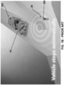
- a vehicle equipped with at least one vehicle device 100 circulates in direction of a person or worker 20 equipped with a personnel device 200 (see Figure 1A ).
- the vehicle device 100 is configured to detect other context-aware device within a certain range and to automatically stop when the vehicle 10 is within a predetermined distance of another vehicle device 10 or person device 20 (see Figure 1B ).
- Such exemplary system has some drawback.
- the vehicle 10 even if the worker 20 is in a safe environment, but within a predetermined range of the vehicle 10 considered critically hazardous, the vehicle 10 will automatically stops upon detection of the worker 20 within the predetermined range. The workers 20 must then move out of the critically hazardous range for the vehicle 10 to move forward, resulting in lost of time and in reduced efficiency.
- the unexpected and sudden stop of the vehicle 10 may eject an operator out of the vehicle 10 if the said operator has not fastened his seatbelt. Such situation may again reduce efficiency and may obviously even lead to serious injuries.
- the method generally comprises the steps of detecting, with at least one context awareness mechanism, if a context-aware device 100, 200 is within a predetermined range or distance (see Figures 2 and 3 ).
- the method further comprises the vehicle device 100 or personal device 200 being within a predetermined range of the moving vehicle 10 sending a request of acknowledgment to the vehicle device 100 or personal device 200 (see Figure 4 ).
- the moving vehicle device 100 does not receive an acknowledgment from another vehicle 30 or a worker 10 within a predetermined duration, the moving vehicle 10 is automatically stopped (see Figure 5 ).
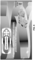
- the device 100 of the moving vehicle considers the context as non-hazardous and the vehicle 10 may continue along its path (see Figure 6 ).
- the method may further comprise detecting a one or more context-aware devices within predetermined ranges.
- a context may be associated with each of the ranges.
- the context may be that the moving vehicle 10 is moving toward a predetermined hazardous range of the person 20 or another vehicle 30.
- the acknowledgment request is sent to each device having a predetermined range which shall be crossed by the moving vehicle.
- the moving vehicle 10 may comprise an interface 110 showing the other devices 100, 200 within a predetermined range.
- the step of sending a request of acknowledgment to each device within the predetermined range may further comprise displaying the time 112 remaining for receiving the acknowledgment from each of the devices 100, 200 presents within a predetermined range.
- the step of sending a request of acknowledgment may further comprise calculating the distance between the moving vehicle 10 and the different devices 100, 200 being part of the same network.
- the various devices 100, 200 communicate with each other directly (e.g. through peer-to-peer network(s)) or indirectly (e.g. through communication network(s)). Once in communication, the various devices will be able to transmit proximity warnings to each other when proximity is detected with the help of various methodologies (e.g. communication range, received signal strength, time of flight, radar, magnetic fields, laser-based location recognition, etc.).
- various methodologies e.g. communication range, received signal strength, time of flight, radar, magnetic fields, laser-based location recognition, etc.
- the various devices 100, 200 communicate directly with each other via peer-to-peer communication.
- proximity between devices 100, 200 is mainly detected by the radio-frequency communication range between various devices.
- the range of proximity detection may vary from as low as 25 meters when devices are around corners with no direct line-of sight, to up to 100 meters when devices have a direct line-of sight.
- the moving vehicle 10 is configured to be automatically stopped.
- the moving vehicle 10 may be configured to automatically slow down close to the end of the duration of the period to receive an acknowledgment from the devices 100, 200.
- the hazard is considered cleared only during a predetermined duration.
- the moving vehicle 10 does not move away or out from the critically hazardous area within the predetermined duration, the moving vehicle 10 is configured to automatically stop.
- the predetermined duration for the moving vehicle 10 to move out or away from the cleared critically hazardous area may be 60 seconds.
- the proximity of this specific device 200 to the vehicle 10 won't trigger a slow down or stop of the vehicle 10. Understandably, such duration may be modified to adapt to other scenarios or other needs of the system.
- the device 100 of the moving vehicle 10 may be configured to send another acknowledgment request to the devices 100, 200 within the critically hazardous area prior to the end of the predetermined duration to move away from the said critically hazardous area. Again, if no acknowledgment response is received from the devices 100, 200 within the critically hazardous area prior to the end of the predetermined duration, the moving vehicle 10 is stopped.
- the context-aware collision devices 200 are incorporated into the cap lamps of the users 20.
- the cap lamp may start to flash to indicate to the user 20 that an acknowledgment request has been received. If the user 20 is in a safe location or indicate that he is in a safe location, the device 200 is configured to send an acknowledgment response to the device 100 of the moving vehicle 10.
- the user 20 may toggle the cap lamp on, toggle the cap lamp off and toggle the cap lamp on again to trigger the device 200 to send the acknowledgement response to the moving vehicle 10.
- any other method for triggering the communication of an acknowledgment response to the moving vehicle 10 are within the scope of the present invention.
- any other sequence of toggling the cap lamp on and/or off may be used or the cap lamp may comprise one or more buttons adapted to send the acknowledgment response to the moving vehicle 10.
- the device 100 of the other vehicle 30 is configured to receive the acknowledgment request.
- the other vehicle 30 comprises a module or unit comprising an interface configured to display the reception of an acknowledgment request.
- the interface is configured for a passenger of the vehicle 30 to trigger the communication of a response to the acknowledgement request to the device 100 of the moving vehicle 10.
- the interface may be any type of known user interface device such a button-based interface, touch-based interface and/or using gestural recognition technologies.
- the method may further comprise automatically detecting that the user 20 or vehicle 30 is within a safe area such as through geo-localization or any other mean to determine that the user 20 or vehicle is within a safe zone.
Landscapes
- Physics & Mathematics (AREA)
- General Physics & Mathematics (AREA)
- Engineering & Computer Science (AREA)
- Computer Networks & Wireless Communication (AREA)
- Signal Processing (AREA)
- Electromagnetism (AREA)
- Aviation & Aerospace Engineering (AREA)
- Radar, Positioning & Navigation (AREA)
- Remote Sensing (AREA)
- Automation & Control Theory (AREA)
- Traffic Control Systems (AREA)
- Loading Or Unloading Of Vehicles (AREA)
- Control Of Position, Course, Altitude, Or Attitude Of Moving Bodies (AREA)
- Forklifts And Lifting Vehicles (AREA)
Description
- The present patent application claims the benefits of priority of
United States Provisional Patent Application No. 62/702,313, entitled "Method and system for acknowledging presence in a context-aware environment" and filed at the United States Patent and Trademark Office on July 23, 2019 - The present invention generally relates to the field of safety devices, apparatuses and/or systems and more particularly to the field of proximity warning and collision avoidance devices, apparatuses and/or systems typically used in mining environments or enclosed environments.
- Numerous underground mines are developed and are in operation throughout the world. Though safety measures are typically deployed to prevent accidents involving collisions between vehicles, machines, personnel and/or obstacles in these mines, accidents unfortunately happen on a regular basis.
- To minimize the risks of collisions, collision avoidance systems are increasingly deployed. These systems come in various configurations and use various technologies, all with their inherent advantages and drawbacks.
-
US2012025964 discloses an example signal generation system for a vehicle capable of different modes of movement that includes a detector to determine at least one property of vehicle movement and an output representative of that at least one property and a selectively variable signal generator includes an input to receive the at least one output representative of the at least one property of vehicle movement and, responsively, generates a selected signal based on the received output. In some examples, a detector on a pedestrian detects the selected signal from the signal generator and, responsively, provides an output indicative of a vehicle in proximity to the pedestrian. In some examples, a trajectory vector is generated for at least two entities of interest based on at least one characteristic of movement of each entity. Each entity's trajectory vector is expanded and each entity's expanded trajectory vector is analyzed for overlap with the other entity's expanded trajectory vector to assess the possibility of a collision between them. -
US2017372563 discloses electronic badges to convey a condition associated with an environment to an industrial vehicle. The process comprises identifying a condition in a limited, defined environment and associating the identified condition with a badge ID. The process also comprises programming an electronic badge based upon the identified condition and positioning the electronic badge within a work area of industrial vehicles. Still further, the process comprises receiving, by a processor on an industrial vehicle, information from the electronic badge including at least one of the associated badge ID and the identified condition. The information is received via a badge communicator that communicates with electronic badges that are within a predetermined range of the industrial vehicle via a first wireless communication link. The process also determines the condition from the information from the electronic badge, and controls the industrial vehicle to take a predetermined action based upon the determined condition. -
WO2017089954 discloses a frame for protective lenses with the smart integrated system comprises a control unit (1) that interprets a danger-identification signal (5) and, via software, activates a light alarm (2) and a perceptive vibrating alarm (3) applied on a sensitive part of the face of the person on foot to create an imminent sense of alert on the risk of being hit even in markedly noisy environments. The vibrating alarm will be acknowledged automatically after the person who is wearing the smart integrated system has directed his own attention to the danger thanks to an optical pointer (4), at the same time leaving his hands free. Multiple risks generate multiple alarms, each of which is managed independently. Various dangers, including ones that deriving from means that are not moving, can be configured by creating visual alarms with different colours. -
US9081046 - One type of collision avoidance systems that is becoming popular in underground mine environments involves the use of typically three types of collision avoidance devices configured to be respectively mounted to vehicles, personnel, and obstacles. These devices are configured to form ad hoc peer-to-peer wireless networks when they are within communication range of each other and can therefore transmit proximity warnings to each other if proximity is detected from various sensors based on received signal strength, time-of-flight, radar, lasers or magnetic fields.
- However, even if these types of collision avoidance systems can provide valuable warnings to enhance safety at mine sites, it remains that these systems do not take into account the context in which the person or the vehicle carrying the device is before transmitting proximity warnings. Hence, these systems often cause the transmission of proximity warnings even though the context does not warrant it.
- Non-limitative examples of non-hazardous proximity warnings include the notification to a vehicle operator of personnel in the area when personnel are passengers in the same or another vehicle, the notification to a vehicle operator of personnel in the area when personnel are in a refuge or other sheltered area, the notification to a vehicle operator of vehicles in the area when the vehicles are parked in a garage, and the notification to personnel of a vehicle in the area when the vehicle is stopped or non-operating.
- Even if context-aware avoidance systems provide ability to distinguish between non-hazardous situations, hazardous situations, and very hazardous or critical situations, some situations may be safe despite the system identifying a context of a hazardous, very hazardous or critical situations. As an example, in a situation where a person, such as a miner, is within a predetermined range of a moving vehicle, the vehicle will automatically stop, even if the person is in a safe environment. Such situation may occur when a person is being in an enclosure but still identified within the range of the vehicle. Such situation may happen many times a day in a mining environment and thus may result in important efficiency losses.
- Hence, in view of the foregoing, there is a need for an improved collision avoidance system, and related devices and methods, purpose-built for underground mines which will at least mitigate some of the shortcomings of systems using collision avoidance devices.
- The shortcomings of the prior art are generally mitigated by a method for acknowledging presence in a context-aware environment comprises the steps of detecting, with at least one context awareness mechanism, if a context-aware device is within a predetermined range or distance. The method further comprises the vehicle device or personal device being within a range of the moving vehicle sending a request of acknowledgment to the vehicle device or personal device. In events where the moving vehicle device does not receive an acknowledgment from another vehicle or a worker within a predetermined duration, the moving vehicle is automatically stopped. In events where the moving vehicle device receives an acknowledgment from all the devices within the predetermined range, the device of the moving vehicle considers the context as non-hazardous and the vehicle may continue along its path.
- In another aspect of the invention, a system for acknowledging presence in a context-aware environment is provided. The system comprises a plurality of context-aware collision avoidance devices configured to connect with each another through a network, such as through a peer-to-peer network. Moving vehicles comprise vehicle devices configured to send acknowledgment requests to all other devices within a range of the path of the vehicle. Each device receiving the acknowledgment request is configured for an operator to communicate an acknowledgement response when the operator, such as a pedestrian or passengers of a vehicle, considers that they are in a safe area. Upon reception of the acknowledgment response, the moving vehicle is configured to move in proximity of the devices having acknowledged without automatically stopping.
- In one aspect of the invention, a method for acknowledging presence of a first context-aware device using a second context-aware device in a context-aware environment is provided. The method comprises detecting with the second context-aware device if the first context-aware device is within a predetermined distance of the second context-aware device, when the first context-aware device is detected within the predetermined distance, the second context-aware device sending a request of acknowledgment to the first context-aware device, if in a safe environment, the first context-aware device sending an acknowledgment to the second context-aware device and upon reception of the acknowledgement from the first context-aware device, the second context-aware considering the context as non-hazardous.
- The method may further comprise that if no acknowledgement is received after a predetermined duration from the second context-aware device sending the request of acknowledgment to the first context-aware device, the context being identified as critically hazardous.
- The method may further comprise upon not receiving acknowledgement prior to a duration prior to predetermined duration, the context being identified as hazardous. The method may further comprise the second context-aware device sending another acknowledgement request to the first context-aware device prior to the end of the predetermined duration.
- The second context-aware device may be in movement. The method may further comprise stopping the movement when the context is critically hazardous.
- The second context-aware device may be in a vehicle. The method may further comprise automatically stopping the vehicle when the context is hazardous. The method may further comprise continuing movement of the vehicle when the context is non-hazardous. The method may further comprise slowing movement of the vehicle when the context is hazardous.
- The method may further comprise calculating the distance between the moving second context-aware device and the first context-aware device.
- The first context-aware device may be in a vehicle or may be worn by a person.
- The context-aware environment may comprise a plurality of first context-aware devices, upon the second context-aware device receiving an acknowledgment from each of the first context-aware devices within the predetermined distance, the context being non-hazardous. The method may further comprise displaying time remaining for receiving the acknowledgment from each of the first context-aware devices.
- In another aspect of the invention, a system for acknowledging presence in a context-aware environment is provided. The system comprises a network and a plurality of context-aware devices comprising at least one first context-aware device configured to be in communication with the other context-aware devices through the network, the first context-aware device being configured to send an acknowledgement to another context-aware device. The context-aware devices further comprise at least one second context-aware device configured to be in communication with the other context-aware devices through the network, wherein the first context-aware device is configured to send an acknowledgement to the second context-aware device and wherein the second context-aware device is configured to detect presence of the first context-aware device within a predetermined distance of the second context-aware device and upon reception of the acknowledgement from the first context-aware device, consider the context as non-hazardous.
- The second context-aware may further be configured that if no acknowledgement is received after a predetermined duration from the second context-aware device sending the request of acknowledgment to the first context-aware device, the context being critically hazardous. The second context-aware device may be within a vehicle or the vehicle may be configured to automatically stop when the context is critically hazardous.
- The second context-aware device may be configured to identify the context as hazardous upon not receiving the acknowledgement prior a predetermined duration. The second context-aware device being within a vehicle and the vehicle being configured to automatically slow down when the context is hazardous.
- The first context-aware device may be within a vehicle. The vehicle may comprise an interface configured to display the reception of the acknowledgment request. The interface may be configured to trigger the communication of a response to the received acknowledgement request.
- The second context-aware device may use radio-frequency communication range to detect the first context-aware device. The first context-aware device may be further configured to generate an alarm when receiving a notification of an approaching second context-aware device.
- The first context-aware device may be integrated into a cap lamp. The cap lamp being may be configured to flash when the first context-aware device receives the acknowledgement request from the second context-aware device. The cap lamp may be configured to be toggled on or off, the toggle of the cap lamp triggering the first context-aware device to send the acknowledgement to the received acknowledgement request.
- The system may comprise a plurality of first context-aware devices, the second context-aware device being configured to identify the context as being non-hazardous upon receiving an acknowledgment from each of the first context-aware devices.
- Other and further aspects and advantages of the present invention will be obvious upon an understanding of the illustrative embodiments about to be described or will be indicated in the appended claims, and various advantages not referred to herein will occur to one skilled in the art upon employment of the invention in practice.
- The above and other aspects, features and advantages of the invention will become more readily apparent from the following description, reference being made to the accompanying drawings in which:
-
Figure 1A and1B are illustrations of a prior art system for detecting a person in a restricted area. -
Figure 2 is an illustration of detection of a person in an embodiment of a method for acknowledging presence in a context-aware environment. -
Figure 3 is an illustration of detection of a vehicle in an embodiment of a method for acknowledging presence in a context-aware environment. -
Figure 4 is an illustration of prompting for acknowledgment of a person in an embodiment of a method for acknowledging presence in a context-aware environment. -
Figure 5 is an illustration of non-acknowledgment of a person in an embodiment of a method for acknowledging presence in a context-aware environment. -
Figure 6 is an illustration of acknowledgment of a person in an embodiment of a method for acknowledging presence in a context-aware environment. - A novel method and system for acknowledging presence in a context-aware environment will be described hereinafter. Although the invention is described in terms of specific illustrative embodiments, it is to be understood that the embodiments described herein are by way of example only and that the scope of the invention is not intended to be limited thereby.
- As a preliminary matter, it will readily be understood by one having ordinary skill in the relevant art ("Ordinary Artisan") that the invention has broad utility and application. Furthermore, any embodiment discussed and identified as being "preferred" is considered to be part of a best mode contemplated for carrying out the invention. Other embodiments also may be discussed for additional illustrative purposes in providing a full and enabling disclosure of the invention. Furthermore, an embodiment of the invention may incorporate only one or a plurality of the aspects of the invention disclosed herein; only one or a plurality of the features disclosed herein; or combination thereof. As such, many embodiments are implicitly disclosed herein and fall within the scope of what is regarded as the invention.
- Thus, for example, any sequence(s) and/or temporal order of steps of various processes or methods that are described herein are illustrative and not restrictive. Accordingly, it should be understood that, although steps of various processes or methods may be shown and described as being in a sequence or temporal order, the steps of any such processes or methods are not limited to being carried out in any particular sequence or order, absent an indication otherwise. Indeed, the steps in such processes or methods generally may be carried out in various different sequences and orders while still falling within the scope of the invention. Accordingly, it is intended that the scope of patent protection afforded the invention is to be defined by the issued claim(s) rather than the description set forth herein.
- Additionally, it is important to note that each term used herein refers to that which the Ordinary Artisan would understand such term to mean based on the contextual use of such term herein. To the extent that the meaning of a term used herein-as understood by the Ordinary Artisan based on the contextual use of such term-differs in any way from any particular dictionary definition of such term, it is intended that the meaning of the term as understood by the Ordinary Artisan should prevail.
- With regard solely to construction of any claim with respect to the United States, no claim element is to be interpreted under 35 U.S.C. 112(f) unless the explicit phrase "means for" or "step for" is actually used in such claim element, whereupon this statutory provision is intended to and should apply in the interpretation of such claim element. With regard to any method claim including a condition precedent step, such method requires the condition precedent to be met and the step to be performed at least once during performance of the claimed method.
- When used herein to join a list of items, "or" denotes "at least one of the items," but does not exclude a plurality of items of the list. Thus, reference to "a picnic basket having cheese or crackers" describes "a picnic basket having cheese without crackers", "a picnic basket having crackers without cheese", and "a picnic basket having both cheese and crackers." When used herein to join a list of items, "and" denotes "all of the items of the list." Thus, reference to "a picnic basket having cheese and crackers" describes "a picnic basket having cheese, wherein the picnic basket further has crackers," as well as describes "a picnic basket having crackers, wherein the picnic basket further has cheese."
- The context-aware collision avoidance devices referred to in the context of the present invention are generally deployed within collision avoidance systems of the type comprising different types of devices configured to be respectively mounted to, or carried by, mobile vehicles and machinery, fixed hazards or obstacles, and personnel, such as devices and system disclosed in US patent application published under no.
US 2015/0274072 A1 , the content of which is incorporated herein. - Typically, such collision avoidance systems comprise three types of devices, namely: 1) vehicle devices to be mounted to mobile vehicles and machinery (collectively referred to as "vehicles"), 2) obstacle devices to be mounted to obstacle and other fixed hazards (collectively referred to as "obstacles"), and 3) personnel devices to be carried by personnel (e.g. vehicle operators, worker, miners, etc.).
- In operation, the various devices will communicate with each other directly (e.g. through peer-to-peer network(s)) or indirectly (e.g. through communication network(s)). Once in communication, the various devices will be able to transmit proximity warnings to each other when proximity is detected with the help of various methodologies (e.g. communication range, received signal strength, time of flight, radar, magnetic fields, laser-based location recognition, etc.).
- Referring now to
Figures 1A and1B , in typical prior art scenario using a system of context-aware collision avoidance devices is illustrated. In such scenario, which is located in an underground mine, a vehicle equipped with at least onevehicle device 100 circulates in direction of a person orworker 20 equipped with a personnel device 200 (seeFigure 1A ). Thevehicle device 100 is configured to detect other context-aware device within a certain range and to automatically stop when thevehicle 10 is within a predetermined distance of anothervehicle device 10 or person device 20 (seeFigure 1B ). - Such exemplary system has some drawback. Amongst others, in the scenario shown in
Figures 1A and1B , even if theworker 20 is in a safe environment, but within a predetermined range of thevehicle 10 considered critically hazardous, thevehicle 10 will automatically stops upon detection of theworker 20 within the predetermined range. Theworkers 20 must then move out of the critically hazardous range for thevehicle 10 to move forward, resulting in lost of time and in reduced efficiency. In some other situations, the unexpected and sudden stop of thevehicle 10 may eject an operator out of thevehicle 10 if the said operator has not fastened his seatbelt. Such situation may again reduce efficiency and may obviously even lead to serious injuries. - Referring now to
Figures 2 to 6 , a method for acknowledging presence in a context-aware environment is illustrated. The method generally comprises the steps of detecting, with at least one context awareness mechanism, if a context-aware device Figures 2 and3 ). The method further comprises thevehicle device 100 orpersonal device 200 being within a predetermined range of the movingvehicle 10 sending a request of acknowledgment to thevehicle device 100 or personal device 200 (seeFigure 4 ). In events where the movingvehicle device 100 does not receive an acknowledgment from anothervehicle 30 or aworker 10 within a predetermined duration, the movingvehicle 10 is automatically stopped (seeFigure 5 ). In events where the movingvehicle device 100 receives an acknowledgment from all thedevices device 100 of the moving vehicle considers the context as non-hazardous and thevehicle 10 may continue along its path (seeFigure 6 ). - Referring back to
Figures 2 and3 , the method may further comprise detecting a one or more context-aware devices within predetermined ranges. A context may be associated with each of the ranges. As examples, the context may be that the movingvehicle 10 is moving toward a predetermined hazardous range of theperson 20 or anothervehicle 30. In such context, the acknowledgment request is sent to each device having a predetermined range which shall be crossed by the moving vehicle. - Referring now to
Figure 4 , the movingvehicle 10 may comprise aninterface 110 showing theother devices time 112 remaining for receiving the acknowledgment from each of thedevices vehicle 10 and thedifferent devices - In some embodiments, the
various devices - In the present embodiment, the
various devices devices - Now referring to
Figure 5 , if aperson 20 or avehicle 30 requested to acknowledge within a predetermined duration does not send an acknowledgment response to thedevice 100 of the movingvehicles 10, the movingvehicle 10 is configured to be automatically stopped. - In some embodiments, the moving
vehicle 10 may be configured to automatically slow down close to the end of the duration of the period to receive an acknowledgment from thedevices - Now referring to
Figure 6 , if all of thedevices device 100 of the movingvehicle 10, the hazard is considered cleared and the movingvehicle 10 may move within a critically hazardous area without being automatically stopped. - In some embodiments, the hazard is considered cleared only during a predetermined duration. Thus, if the moving
vehicle 10 does not move away or out from the critically hazardous area within the predetermined duration, the movingvehicle 10 is configured to automatically stop. - In some embodiments, the predetermined duration for the moving
vehicle 10 to move out or away from the cleared critically hazardous area may be 60 seconds. Thus, the proximity of thisspecific device 200 to thevehicle 10 won't trigger a slow down or stop of thevehicle 10. Understandably, such duration may be modified to adapt to other scenarios or other needs of the system. - In yet other embodiments, in a similar scenario, the
device 100 of the movingvehicle 10 may be configured to send another acknowledgment request to thedevices devices vehicle 10 is stopped. - In some embodiments, the context-
aware collision devices 200 are incorporated into the cap lamps of theusers 20. When thedevice 200 receives notification of an approaching vehicle, an alarm is generated on thedevice 200. In some embodiments, the cap lamp may start to flash to indicate to theuser 20 that an acknowledgment request has been received. If theuser 20 is in a safe location or indicate that he is in a safe location, thedevice 200 is configured to send an acknowledgment response to thedevice 100 of the movingvehicle 10. - As an example, the
user 20 may toggle the cap lamp on, toggle the cap lamp off and toggle the cap lamp on again to trigger thedevice 200 to send the acknowledgement response to the movingvehicle 10. Understandably, any other method for triggering the communication of an acknowledgment response to the movingvehicle 10 are within the scope of the present invention. As an example, any other sequence of toggling the cap lamp on and/or off may be used or the cap lamp may comprise one or more buttons adapted to send the acknowledgment response to the movingvehicle 10. - In examples where more than one
user 20 in a group ofusers 20 within a range that the movingvehicle 10 will cross receive an acknowledgement request, if all theusers 20 send the acknowledgement response to the movingvehicle 10, then the vehicle will be able to pass through the group, in proximity of theusers 20, without slowing down or stopping. - In examples where another
vehicle 30 is within a range that the movingvehicle 10 will cross, thedevice 100 of theother vehicle 30 is configured to receive the acknowledgment request. In some embodiments, theother vehicle 30 comprises a module or unit comprising an interface configured to display the reception of an acknowledgment request. In such embodiments, the interface is configured for a passenger of thevehicle 30 to trigger the communication of a response to the acknowledgement request to thedevice 100 of the movingvehicle 10. The interface may be any type of known user interface device such a button-based interface, touch-based interface and/or using gestural recognition technologies. - In examples where more than one
user 20 and/orvehicles 30 are within a range that the movingvehicle 10 will cross and receive an acknowledgement request, if all theusers 20 and/orvehicles 30 send the acknowledgement response to the movingvehicle 10, then the vehicle will be able to pass through the group ofusers 20 andvehicles 30, in proximity of theusers 20 and/orvehicles 30, without slowing down or stopping. - The method may further comprise automatically detecting that the
user 20 orvehicle 30 is within a safe area such as through geo-localization or any other mean to determine that theuser 20 or vehicle is within a safe zone. - While illustrative and presently preferred embodiments of the invention have been described in detail hereinabove, it is to be understood that the inventive concepts may be otherwise variously embodied and employed and that the appended claims are intended to be construed to include such variations except insofar as limited by the prior art.
Claims (13)
- A method for acknowledging presence of a first collision avoidance device (200) using a second collision avoidance device (100) in an underground mine environment, the method comprising:a) detecting with the second collision avoidance device (100) if the first collision avoidance device (200) is within a predetermined distance of the second collision avoidance device (100);b) when the first collision avoidance device (200) is detected within the predetermined distance, the second collision avoidance device (100) sending a request of acknowledgment to the first collision avoidance device (200);c) if the first collision avoidance device (200) is in a safe environment, receiving an acknowledgment from the first collision avoidance device (200) by the second collision avoidance device (100);d) upon reception of the acknowledgement from the first collision avoidance device (200), the second collision avoidance device (100) considering a context as non-hazardous.
- The method of claim 1, the method further comprising if no acknowledgement has been received after a predetermined duration from the second collision avoidance device (100) sending the request of acknowledgment to the first collision avoidance device (200), the context being identified as critically hazardous.
- The method of claim 2, the method further comprising upon not receiving acknowledgement prior to a predetermined duration, the context being identified as hazardous.
- The method of claim 1, the second collision avoidance device (100) being in movement and the second collision avoidance device (100) being in a vehicle (10), the method further comprising stopping the movement when the context is critically hazardous.
- The method of claim 4, the method further comprising continuing movement of the vehicle (10) when the context is non-hazardous.
- The method of claim 1, the underground mine environment comprising a plurality of first collision avoidance devices (200), upon the second collision avoidance device (100) receiving an acknowledgment from each of the first collision avoidance devices (200) within the predetermined distance, the context being non-hazardous.
- A method for acknowledging presence of a first collision avoidance device (200) with a second collision avoidance device (100) in an underground mine environment, the method comprising:a) when the first collision avoidance device (200) is within a predetermined range from the second collision avoidance device (100), receiving by the first collision avoidance device (200) a request of acknowledgment from the second collision avoidance device (100);b) if the first collision avoidance device (200) is in a safe environment, receiving a trigger from a user for sending an acknowledgement from the first collision avoidance device (200);c) sending the acknowledgment from the first collision avoidance device (200) to the second collision avoidance device (100).
- A second collision avoidance device (100) configured to acknowledge presence of a first collision avoidance device (200) in an underground mine environment, the second collision avoidance device (100) being a vehicle collision avoidance device (100), the second collision avoidance device (100) being further configured to:a) detect if the first collision avoidance device (200) is within a predetermined distance of the second collision avoidance device (100);b) send, when the first collision avoidance device (200) is detected within the predetermined distance, a request of acknowledgment to the first collision avoidance device (200);c) receive, if the first collision avoidance device (200) is in a safe environment, an acknowledgment sent from the first collision avoidance device (200);d) consider, upon reception of the acknowledgement from the first collision avoidance device (200), the context as non-hazardous.
- The second collision avoidance device (100) according to claim 8, further configured to carry out the method according to any of the claims 2 to 6.
- A first collision avoidance device (200) for acknowledging presence with a second collision avoidance device (100) in an underground mine environment, the first collision avoidance device (200) being a personnel collision avoidance device (200), the first collision avoidance device (200) being further configured to:a) receive, when being within predetermined range from the second collision avoidance device (100), a request of acknowledgment from the second collision avoidance device (100);b) if the first collision avoidance device (200) is in a safe environment, receive a trigger from a user for sending an acknowledgement from the first collision avoidance device (200);c) send the acknowledgment from the first collision avoidance device (200) to the second collision avoidance device (100).
- A system for acknowledging presence in an underground mine environment, the system comprising:a) a network;b) a plurality of collision avoidance devices (100, 200) comprising:i) at least one first collision avoidance device (200) according to claim 10 configured to be in communication with the other collision avoidance devices through the network;ii) the first collision avoidance device (200) being configured to send an acknowledgement to another collision avoidance device; andiii) at least one second collision avoidance device (100) according to any of claims 8 to 9 J configured to be in communication with the other collision avoidance devices through the network;
- The system of claim 11, the second collision avoidance (100) being further configured that if no acknowledgement has been received after a predetermined duration from the second collision avoidance device (100) sending the request of acknowledgment to the first collision avoidance device (200), the context being identified as critically hazardous, the second collision avoidance device (100) being within a vehicle (10) and the vehicle (10) being configured to automatically stop when the context is critically hazardous.
- The system of claim 11, the first collision avoidance device (200) being integrated into a cap lamp, the cap lamp being configured to flash when the first collision avoidance device (200) receives the acknowledgement request from the second collision avoidance device (100), and the cap lamp being configured to be toggled on or off, the toggle of the cap lamp triggering the first collision avoidance device (200) to send the acknowledgement to the received acknowledgement request.
Applications Claiming Priority (2)
| Application Number | Priority Date | Filing Date | Title |
|---|---|---|---|
| US201862702313P | 2018-07-23 | 2018-07-23 | |
| PCT/CA2019/051016 WO2020019071A1 (en) | 2018-07-23 | 2019-07-23 | Method and system for acknowledging presence in a context-aware environment |
Publications (4)
| Publication Number | Publication Date |
|---|---|
| EP3827424A1 EP3827424A1 (en) | 2021-06-02 |
| EP3827424A4 EP3827424A4 (en) | 2022-04-13 |
| EP3827424B1 true EP3827424B1 (en) | 2024-04-24 |
| EP3827424C0 EP3827424C0 (en) | 2024-04-24 |
Family
ID=69180825
Family Applications (1)
| Application Number | Title | Priority Date | Filing Date |
|---|---|---|---|
| EP19842080.4A Active EP3827424B1 (en) | 2018-07-23 | 2019-07-23 | Method and system for acknowledging presence in a context-aware environment |
Country Status (10)
| Country | Link |
|---|---|
| US (1) | US11756426B2 (en) |
| EP (1) | EP3827424B1 (en) |
| CN (1) | CN112513957A (en) |
| AU (1) | AU2019310654B2 (en) |
| CA (1) | CA3106117A1 (en) |
| CL (1) | CL2021000151A1 (en) |
| MX (1) | MX2021000854A (en) |
| PE (1) | PE20210352A1 (en) |
| WO (1) | WO2020019071A1 (en) |
| ZA (1) | ZA202100178B (en) |
Family Cites Families (46)
| Publication number | Priority date | Publication date | Assignee | Title |
|---|---|---|---|---|
| US5568121A (en) * | 1993-05-27 | 1996-10-22 | Lamensdorf; David M. | Wireless system for sensing information at remote locations and communicating with a main monitoring center |
| US6406785B1 (en) * | 1998-07-16 | 2002-06-18 | Schlegel Corporation | Weatherseal having a contact layer with thermoplastic particles in a thermoset carrier |
| KR101833739B1 (en) * | 2006-12-13 | 2018-03-02 | 크라운 이큅먼트 코포레이션 | Fleet management system |
| CN102105918A (en) * | 2008-06-25 | 2011-06-22 | 层近系统有限责任公司 | Personal alarm device for helmets used in proximity detection systems |
| JP5486866B2 (en) | 2009-07-29 | 2014-05-07 | ルネサスエレクトロニクス株式会社 | Manufacturing method of semiconductor device |
| US20110128161A1 (en) * | 2009-11-30 | 2011-06-02 | Gm Global Technology Operations, Inc. | Vehicular warning device for pedestrians |
| US8922431B2 (en) * | 2010-04-13 | 2014-12-30 | Becker Research And Development (Proprietary) Limited | Apparatus, a system and a method for collission avoidance |
| FI122157B (en) * | 2010-05-10 | 2011-09-15 | Sandvik Mining & Constr Oy | Methods and apparatus for safety devices of mining vehicles |
| US9230419B2 (en) * | 2010-07-27 | 2016-01-05 | Rite-Hite Holding Corporation | Methods and apparatus to detect and warn proximate entities of interest |
| CA2735458A1 (en) * | 2011-03-22 | 2012-09-22 | Denis Hugron | Interactive system for preventing automobile accidents caused by not following the rules of the road, method of producing and using said system with vehicles |
| FR2977358B1 (en) * | 2011-06-29 | 2013-08-09 | Gilles Vaquin | WARNING SYSTEM OF HAZARDOUS SITUATIONS IN AGGRESSIVE ENVIRONMENT |
| AU2012294530B2 (en) * | 2011-08-08 | 2015-05-28 | Strata Safety Products, Llc | Proximity detection system with concurrent RF and magnetic fields |
| JP5472238B2 (en) * | 2011-08-29 | 2014-04-16 | 株式会社デンソー | VEHICLE RADIO COMMUNICATION DEVICE AND COMMUNICATION SYSTEM |
| DE102011111899A1 (en) * | 2011-08-30 | 2013-02-28 | Gm Global Technology Operations, Llc | Detection device and method for detecting a carrier of a transceiver, motor vehicle |
| JP5978582B2 (en) * | 2011-09-28 | 2016-08-24 | 住友電気工業株式会社 | Vehicle detection device, abnormality detection method, and abnormality detection program |
| US9000903B2 (en) * | 2012-07-09 | 2015-04-07 | Elwha Llc | Systems and methods for vehicle monitoring |
| AU2013315672B2 (en) * | 2012-09-12 | 2017-09-14 | Strata Safety Products, Llc | Integrated alarm device |
| CA2887511C (en) * | 2012-10-12 | 2018-11-06 | Newtrax Holdings Inc. | Context-aware collision avoidance devices and collision avoidance system comprising the same |
| CA2849465C (en) * | 2013-07-30 | 2016-12-20 | Masanori Tojima | Management system and management method of mining machine |
| JP5714129B1 (en) * | 2013-07-30 | 2015-05-07 | 株式会社小松製作所 | Mining machine management system and management method |
| JP6429368B2 (en) * | 2013-08-02 | 2018-11-28 | 本田技研工業株式会社 | Inter-vehicle communication system and method |
| US9505412B2 (en) * | 2013-08-02 | 2016-11-29 | Honda Motor Co., Ltd. | System and method for detection and utilization of driver distraction level |
| US9508199B2 (en) * | 2013-08-09 | 2016-11-29 | Honda Motor Co., Ltd. | Mobile device communicating with motor vehicle system |
| US9349293B2 (en) * | 2014-02-07 | 2016-05-24 | Here Global B.V | Method and apparatus for providing vehicle synchronization to facilitate a crossing |
| JP6262068B2 (en) * | 2014-04-25 | 2018-01-17 | 日立建機株式会社 | Near-body obstacle notification system |
| EP2993083B1 (en) * | 2014-09-04 | 2023-11-22 | Nokia Technologies Oy | Apparatus, method and computer program for controlling road user acknowledgement |
| US20170105106A1 (en) * | 2015-01-19 | 2017-04-13 | Hsiang-Fong Tsai | Early-warning system for disasters |
| US9685086B2 (en) * | 2015-05-27 | 2017-06-20 | Cisco Technology, Inc. | Power conservation in traffic safety applications |
| KR20170015115A (en) * | 2015-07-30 | 2017-02-08 | 삼성전자주식회사 | Autonomous vehicle and method for controlling the autonomous vehicle |
| WO2017045143A1 (en) * | 2015-09-16 | 2017-03-23 | SZ DJI Technology Co., Ltd. | Systems and methods for positioning of uav |
| JP2017068335A (en) * | 2015-09-28 | 2017-04-06 | ルネサスエレクトロニクス株式会社 | Data processing device and on-vehicle communication device |
| ITUB20159238A1 (en) | 2015-11-25 | 2017-05-25 | Beniamino Tambelli | frame for protective lenses with integrated intelligent system to detect interference between pedestrian and forklift / vehicle in motion |
| US10117186B2 (en) * | 2016-03-24 | 2018-10-30 | Motorola Mobility Llc | Apparatuses and methods for controlling always-on displays for mobile devices |
| US20170278385A1 (en) * | 2016-03-24 | 2017-09-28 | Shawn Robert Jevne | Smart wristband safety warning system |
| AU2017281539B2 (en) * | 2016-06-24 | 2023-05-18 | Crown Equipment Corporation | Electronic badge as a talking marker |
| US10086839B2 (en) * | 2016-09-21 | 2018-10-02 | Ford Global Technologies, Llc | Semiautonomous vehicle control system |
| US20180122218A1 (en) * | 2016-10-28 | 2018-05-03 | Brian Shanley | Proximity alarm system and method of operating same |
| DE102016224516A1 (en) * | 2016-12-08 | 2018-06-14 | Robert Bosch Gmbh | Method and device for recognizing at least one pedestrian by a vehicle |
| US10473793B2 (en) * | 2017-01-19 | 2019-11-12 | Ford Global Technologies, Llc | V2V collaborative relative positioning system |
| US10440536B2 (en) * | 2017-05-19 | 2019-10-08 | Waymo Llc | Early boarding of passengers in autonomous vehicles |
| JP6717272B2 (en) * | 2017-08-01 | 2020-07-01 | トヨタ自動車株式会社 | Out-of-vehicle notification device |
| JP6690612B2 (en) * | 2017-08-03 | 2020-04-28 | トヨタ自動車株式会社 | Out-of-vehicle alarm device |
| US10509410B2 (en) * | 2017-12-06 | 2019-12-17 | Zoox, Inc. | External control of an autonomous vehicle |
| US20200229144A1 (en) * | 2019-01-10 | 2020-07-16 | Qualcomm Incorporated | Resource reservation techniques for wireless communications |
| US12133192B2 (en) * | 2020-03-25 | 2024-10-29 | Qualcomm Incorporated | Sidelink positioning: switching between round-trip-time and single-trip-time positioning |
| US11304040B2 (en) * | 2020-07-14 | 2022-04-12 | Qualcomm Incorporated | Linking an observed pedestrian with a V2X device |
-
2019
- 2019-07-23 CA CA3106117A patent/CA3106117A1/en active Pending
- 2019-07-23 PE PE2020002241A patent/PE20210352A1/en unknown
- 2019-07-23 AU AU2019310654A patent/AU2019310654B2/en active Active
- 2019-07-23 CN CN201980048269.8A patent/CN112513957A/en active Pending
- 2019-07-23 WO PCT/CA2019/051016 patent/WO2020019071A1/en not_active Ceased
- 2019-07-23 US US17/261,669 patent/US11756426B2/en active Active
- 2019-07-23 EP EP19842080.4A patent/EP3827424B1/en active Active
- 2019-07-23 MX MX2021000854A patent/MX2021000854A/en unknown
-
2021
- 2021-01-11 ZA ZA2021/00178A patent/ZA202100178B/en unknown
- 2021-01-19 CL CL2021000151A patent/CL2021000151A1/en unknown
Also Published As
| Publication number | Publication date |
|---|---|
| ZA202100178B (en) | 2024-07-31 |
| US11756426B2 (en) | 2023-09-12 |
| CN112513957A (en) | 2021-03-16 |
| AU2019310654B2 (en) | 2024-08-15 |
| US20210272461A1 (en) | 2021-09-02 |
| MX2021000854A (en) | 2021-03-26 |
| PE20210352A1 (en) | 2021-02-25 |
| EP3827424A4 (en) | 2022-04-13 |
| AU2019310654A1 (en) | 2021-02-04 |
| CA3106117A1 (en) | 2020-01-30 |
| EP3827424C0 (en) | 2024-04-24 |
| EP3827424A1 (en) | 2021-06-02 |
| CL2021000151A1 (en) | 2021-07-02 |
| WO2020019071A1 (en) | 2020-01-30 |
Similar Documents
| Publication | Publication Date | Title |
|---|---|---|
| US11790784B2 (en) | Proximity detection system and method and collision avoidance system and method using proximity detection | |
| AU2013330131B2 (en) | Context-aware collision avoidance devices and collision avoidance system comprising the same | |
| AU2017206204B2 (en) | Proximity detection system with concurrent RF and magnetic fields | |
| US9836941B2 (en) | Heavy equipment proximity alert system | |
| CN110231819A (en) | System for avoiding collision and the method for avoiding collision | |
| KR102918901B1 (en) | Equipment and system for operator safety management of heavy equipment | |
| AU2019310654B2 (en) | Method and system for acknowledging presence in a context-aware environment |
Legal Events
| Date | Code | Title | Description |
|---|---|---|---|
| STAA | Information on the status of an ep patent application or granted ep patent |
Free format text: STATUS: THE INTERNATIONAL PUBLICATION HAS BEEN MADE |
|
| PUAI | Public reference made under article 153(3) epc to a published international application that has entered the european phase |
Free format text: ORIGINAL CODE: 0009012 |
|
| STAA | Information on the status of an ep patent application or granted ep patent |
Free format text: STATUS: REQUEST FOR EXAMINATION WAS MADE |
|
| 17P | Request for examination filed |
Effective date: 20210223 |
|
| AK | Designated contracting states |
Kind code of ref document: A1 Designated state(s): AL AT BE BG CH CY CZ DE DK EE ES FI FR GB GR HR HU IE IS IT LI LT LU LV MC MK MT NL NO PL PT RO RS SE SI SK SM TR |
|
| DAV | Request for validation of the european patent (deleted) | ||
| DAX | Request for extension of the european patent (deleted) | ||
| REG | Reference to a national code |
Ref country code: DE Ref legal event code: R079 Free format text: PREVIOUS MAIN CLASS: G08G0001160000 Ipc: G05D0001020000 Ref country code: DE Ref legal event code: R079 Ref document number: 602019051054 Country of ref document: DE Free format text: PREVIOUS MAIN CLASS: G08G0001160000 Ipc: G05D0001020000 |
|
| A4 | Supplementary search report drawn up and despatched |
Effective date: 20220314 |
|
| RIC1 | Information provided on ipc code assigned before grant |
Ipc: H04W 84/18 20090101ALI20220308BHEP Ipc: H04W 8/20 20090101ALI20220308BHEP Ipc: H04W 4/80 20180101ALI20220308BHEP Ipc: G08B 21/02 20060101ALI20220308BHEP Ipc: G08G 1/16 20060101ALI20220308BHEP Ipc: G05D 1/02 20200101AFI20220308BHEP |
|
| P01 | Opt-out of the competence of the unified patent court (upc) registered |
Effective date: 20230603 |
|
| GRAP | Despatch of communication of intention to grant a patent |
Free format text: ORIGINAL CODE: EPIDOSNIGR1 |
|
| STAA | Information on the status of an ep patent application or granted ep patent |
Free format text: STATUS: GRANT OF PATENT IS INTENDED |
|
| INTG | Intention to grant announced |
Effective date: 20231117 |
|
| GRAS | Grant fee paid |
Free format text: ORIGINAL CODE: EPIDOSNIGR3 |
|
| GRAA | (expected) grant |
Free format text: ORIGINAL CODE: 0009210 |
|
| STAA | Information on the status of an ep patent application or granted ep patent |
Free format text: STATUS: THE PATENT HAS BEEN GRANTED |
|
| AK | Designated contracting states |
Kind code of ref document: B1 Designated state(s): AL AT BE BG CH CY CZ DE DK EE ES FI FR GB GR HR HU IE IS IT LI LT LU LV MC MK MT NL NO PL PT RO RS SE SI SK SM TR |
|
| REG | Reference to a national code |
Ref country code: GB Ref legal event code: FG4D |
|
| REG | Reference to a national code |
Ref country code: CH Ref legal event code: EP |
|
| REG | Reference to a national code |
Ref country code: DE Ref legal event code: R096 Ref document number: 602019051054 Country of ref document: DE |
|
| REG | Reference to a national code |
Ref country code: IE Ref legal event code: FG4D |
|
| U01 | Request for unitary effect filed |
Effective date: 20240524 |
|
| U07 | Unitary effect registered |
Designated state(s): AT BE BG DE DK EE FI FR IT LT LU LV MT NL PT SE SI Effective date: 20240708 |
|
| P04 | Withdrawal of opt-out of the competence of the unified patent court (upc) registered |
Free format text: CASE NUMBER: APP_39815/2024 Effective date: 20240704 |
|
| U20 | Renewal fee for the european patent with unitary effect paid |
Year of fee payment: 6 Effective date: 20240726 |
|
| PG25 | Lapsed in a contracting state [announced via postgrant information from national office to epo] |
Ref country code: IS Free format text: LAPSE BECAUSE OF FAILURE TO SUBMIT A TRANSLATION OF THE DESCRIPTION OR TO PAY THE FEE WITHIN THE PRESCRIBED TIME-LIMIT Effective date: 20240824 |
|
| PG25 | Lapsed in a contracting state [announced via postgrant information from national office to epo] |
Ref country code: HR Free format text: LAPSE BECAUSE OF FAILURE TO SUBMIT A TRANSLATION OF THE DESCRIPTION OR TO PAY THE FEE WITHIN THE PRESCRIBED TIME-LIMIT Effective date: 20240424 |
|
| PG25 | Lapsed in a contracting state [announced via postgrant information from national office to epo] |
Ref country code: GR Free format text: LAPSE BECAUSE OF FAILURE TO SUBMIT A TRANSLATION OF THE DESCRIPTION OR TO PAY THE FEE WITHIN THE PRESCRIBED TIME-LIMIT Effective date: 20240725 |
|
| PG25 | Lapsed in a contracting state [announced via postgrant information from national office to epo] |
Ref country code: ES Free format text: LAPSE BECAUSE OF FAILURE TO SUBMIT A TRANSLATION OF THE DESCRIPTION OR TO PAY THE FEE WITHIN THE PRESCRIBED TIME-LIMIT Effective date: 20240424 |
|
| PG25 | Lapsed in a contracting state [announced via postgrant information from national office to epo] |
Ref country code: PL Free format text: LAPSE BECAUSE OF FAILURE TO SUBMIT A TRANSLATION OF THE DESCRIPTION OR TO PAY THE FEE WITHIN THE PRESCRIBED TIME-LIMIT Effective date: 20240424 |
|
| PG25 | Lapsed in a contracting state [announced via postgrant information from national office to epo] |
Ref country code: PL Free format text: LAPSE BECAUSE OF FAILURE TO SUBMIT A TRANSLATION OF THE DESCRIPTION OR TO PAY THE FEE WITHIN THE PRESCRIBED TIME-LIMIT Effective date: 20240424 Ref country code: NO Free format text: LAPSE BECAUSE OF FAILURE TO SUBMIT A TRANSLATION OF THE DESCRIPTION OR TO PAY THE FEE WITHIN THE PRESCRIBED TIME-LIMIT Effective date: 20240724 Ref country code: IS Free format text: LAPSE BECAUSE OF FAILURE TO SUBMIT A TRANSLATION OF THE DESCRIPTION OR TO PAY THE FEE WITHIN THE PRESCRIBED TIME-LIMIT Effective date: 20240824 Ref country code: HR Free format text: LAPSE BECAUSE OF FAILURE TO SUBMIT A TRANSLATION OF THE DESCRIPTION OR TO PAY THE FEE WITHIN THE PRESCRIBED TIME-LIMIT Effective date: 20240424 Ref country code: GR Free format text: LAPSE BECAUSE OF FAILURE TO SUBMIT A TRANSLATION OF THE DESCRIPTION OR TO PAY THE FEE WITHIN THE PRESCRIBED TIME-LIMIT Effective date: 20240725 Ref country code: ES Free format text: LAPSE BECAUSE OF FAILURE TO SUBMIT A TRANSLATION OF THE DESCRIPTION OR TO PAY THE FEE WITHIN THE PRESCRIBED TIME-LIMIT Effective date: 20240424 Ref country code: RS Free format text: LAPSE BECAUSE OF FAILURE TO SUBMIT A TRANSLATION OF THE DESCRIPTION OR TO PAY THE FEE WITHIN THE PRESCRIBED TIME-LIMIT Effective date: 20240724 |
|
| P05 | Withdrawal of opt-out of the competence of the unified patent court (upc) changed |
Free format text: CASE NUMBER: APP_39815/2024 Effective date: 20240708 |
|
| PG25 | Lapsed in a contracting state [announced via postgrant information from national office to epo] |
Ref country code: CZ Free format text: LAPSE BECAUSE OF FAILURE TO SUBMIT A TRANSLATION OF THE DESCRIPTION OR TO PAY THE FEE WITHIN THE PRESCRIBED TIME-LIMIT Effective date: 20240424 |
|
| PG25 | Lapsed in a contracting state [announced via postgrant information from national office to epo] |
Ref country code: SK Free format text: LAPSE BECAUSE OF FAILURE TO SUBMIT A TRANSLATION OF THE DESCRIPTION OR TO PAY THE FEE WITHIN THE PRESCRIBED TIME-LIMIT Effective date: 20240424 Ref country code: RO Free format text: LAPSE BECAUSE OF FAILURE TO SUBMIT A TRANSLATION OF THE DESCRIPTION OR TO PAY THE FEE WITHIN THE PRESCRIBED TIME-LIMIT Effective date: 20240424 |
|
| REG | Reference to a national code |
Ref country code: DE Ref legal event code: R097 Ref document number: 602019051054 Country of ref document: DE |
|
| PG25 | Lapsed in a contracting state [announced via postgrant information from national office to epo] |
Ref country code: SM Free format text: LAPSE BECAUSE OF FAILURE TO SUBMIT A TRANSLATION OF THE DESCRIPTION OR TO PAY THE FEE WITHIN THE PRESCRIBED TIME-LIMIT Effective date: 20240424 |
|
| PG25 | Lapsed in a contracting state [announced via postgrant information from national office to epo] |
Ref country code: SM Free format text: LAPSE BECAUSE OF FAILURE TO SUBMIT A TRANSLATION OF THE DESCRIPTION OR TO PAY THE FEE WITHIN THE PRESCRIBED TIME-LIMIT Effective date: 20240424 Ref country code: SK Free format text: LAPSE BECAUSE OF FAILURE TO SUBMIT A TRANSLATION OF THE DESCRIPTION OR TO PAY THE FEE WITHIN THE PRESCRIBED TIME-LIMIT Effective date: 20240424 Ref country code: RO Free format text: LAPSE BECAUSE OF FAILURE TO SUBMIT A TRANSLATION OF THE DESCRIPTION OR TO PAY THE FEE WITHIN THE PRESCRIBED TIME-LIMIT Effective date: 20240424 Ref country code: CZ Free format text: LAPSE BECAUSE OF FAILURE TO SUBMIT A TRANSLATION OF THE DESCRIPTION OR TO PAY THE FEE WITHIN THE PRESCRIBED TIME-LIMIT Effective date: 20240424 |
|
| PG25 | Lapsed in a contracting state [announced via postgrant information from national office to epo] |
Ref country code: MC Free format text: LAPSE BECAUSE OF FAILURE TO SUBMIT A TRANSLATION OF THE DESCRIPTION OR TO PAY THE FEE WITHIN THE PRESCRIBED TIME-LIMIT Effective date: 20240424 |
|
| PLBE | No opposition filed within time limit |
Free format text: ORIGINAL CODE: 0009261 |
|
| REG | Reference to a national code |
Ref country code: CH Ref legal event code: PL |
|
| STAA | Information on the status of an ep patent application or granted ep patent |
Free format text: STATUS: NO OPPOSITION FILED WITHIN TIME LIMIT |
|
| GBPC | Gb: european patent ceased through non-payment of renewal fee |
Effective date: 20240724 |
|
| 26N | No opposition filed |
Effective date: 20250127 |
|
| PG25 | Lapsed in a contracting state [announced via postgrant information from national office to epo] |
Ref country code: CH Free format text: LAPSE BECAUSE OF NON-PAYMENT OF DUE FEES Effective date: 20240731 |
|
| PG25 | Lapsed in a contracting state [announced via postgrant information from national office to epo] |
Ref country code: GB Free format text: LAPSE BECAUSE OF NON-PAYMENT OF DUE FEES Effective date: 20240724 |
|
| PG25 | Lapsed in a contracting state [announced via postgrant information from national office to epo] |
Ref country code: IE Free format text: LAPSE BECAUSE OF NON-PAYMENT OF DUE FEES Effective date: 20240723 |
|
| U20 | Renewal fee for the european patent with unitary effect paid |
Year of fee payment: 7 Effective date: 20250731 |
|
| PG25 | Lapsed in a contracting state [announced via postgrant information from national office to epo] |
Ref country code: CY Free format text: LAPSE BECAUSE OF FAILURE TO SUBMIT A TRANSLATION OF THE DESCRIPTION OR TO PAY THE FEE WITHIN THE PRESCRIBED TIME-LIMIT; INVALID AB INITIO Effective date: 20190723 |
|
| PG25 | Lapsed in a contracting state [announced via postgrant information from national office to epo] |
Ref country code: HU Free format text: LAPSE BECAUSE OF FAILURE TO SUBMIT A TRANSLATION OF THE DESCRIPTION OR TO PAY THE FEE WITHIN THE PRESCRIBED TIME-LIMIT; INVALID AB INITIO Effective date: 20190723 |