EP3827382B1 - System and method for the assessment of condition in complex operational systems based on multi-level pattern recognition - Google Patents
System and method for the assessment of condition in complex operational systems based on multi-level pattern recognition Download PDFInfo
- Publication number
- EP3827382B1 EP3827382B1 EP19840662.1A EP19840662A EP3827382B1 EP 3827382 B1 EP3827382 B1 EP 3827382B1 EP 19840662 A EP19840662 A EP 19840662A EP 3827382 B1 EP3827382 B1 EP 3827382B1
- Authority
- EP
- European Patent Office
- Prior art keywords
- range
- signal
- level
- block
- condition
- Prior art date
- Legal status (The legal status is an assumption and is not a legal conclusion. Google has not performed a legal analysis and makes no representation as to the accuracy of the status listed.)
- Active
Links
Images




Classifications
-
- G—PHYSICS
- G06—COMPUTING OR CALCULATING; COUNTING
- G06N—COMPUTING ARRANGEMENTS BASED ON SPECIFIC COMPUTATIONAL MODELS
- G06N20/00—Machine learning
-
- G—PHYSICS
- G05—CONTROLLING; REGULATING
- G05B—CONTROL OR REGULATING SYSTEMS IN GENERAL; FUNCTIONAL ELEMENTS OF SUCH SYSTEMS; MONITORING OR TESTING ARRANGEMENTS FOR SUCH SYSTEMS OR ELEMENTS
- G05B23/00—Testing or monitoring of control systems or parts thereof
- G05B23/02—Electric testing or monitoring
- G05B23/0205—Electric testing or monitoring by means of a monitoring system capable of detecting and responding to faults
- G05B23/0218—Electric testing or monitoring by means of a monitoring system capable of detecting and responding to faults characterised by the fault detection method dealing with either existing or incipient faults
- G05B23/0221—Preprocessing measurements, e.g. data collection rate adjustment; Standardization of measurements; Time series or signal analysis, e.g. frequency analysis or wavelets; Trustworthiness of measurements; Indexes therefor; Measurements using easily measured parameters to estimate parameters difficult to measure; Virtual sensor creation; De-noising; Sensor fusion; Unconventional preprocessing inherently present in specific fault detection methods like PCA-based methods
-
- G—PHYSICS
- G05—CONTROLLING; REGULATING
- G05B—CONTROL OR REGULATING SYSTEMS IN GENERAL; FUNCTIONAL ELEMENTS OF SUCH SYSTEMS; MONITORING OR TESTING ARRANGEMENTS FOR SUCH SYSTEMS OR ELEMENTS
- G05B23/00—Testing or monitoring of control systems or parts thereof
- G05B23/02—Electric testing or monitoring
- G05B23/0205—Electric testing or monitoring by means of a monitoring system capable of detecting and responding to faults
- G05B23/0218—Electric testing or monitoring by means of a monitoring system capable of detecting and responding to faults characterised by the fault detection method dealing with either existing or incipient faults
- G05B23/0224—Process history based detection method, e.g. whereby history implies the availability of large amounts of data
- G05B23/024—Quantitative history assessment, e.g. mathematical relationships between available data; Functions therefor; Principal component analysis [PCA]; Partial least square [PLS]; Statistical classifiers, e.g. Bayesian networks, linear regression or correlation analysis; Neural networks
-
- G—PHYSICS
- G05—CONTROLLING; REGULATING
- G05B—CONTROL OR REGULATING SYSTEMS IN GENERAL; FUNCTIONAL ELEMENTS OF SUCH SYSTEMS; MONITORING OR TESTING ARRANGEMENTS FOR SUCH SYSTEMS OR ELEMENTS
- G05B23/00—Testing or monitoring of control systems or parts thereof
- G05B23/02—Electric testing or monitoring
- G05B23/0205—Electric testing or monitoring by means of a monitoring system capable of detecting and responding to faults
- G05B23/0259—Electric testing or monitoring by means of a monitoring system capable of detecting and responding to faults characterized by the response to fault detection
- G05B23/0286—Modifications to the monitored process, e.g. stopping operation or adapting control
- G05B23/0289—Reconfiguration to prevent failure, e.g. usually as a reaction to incipient failure detection
-
- G—PHYSICS
- G06—COMPUTING OR CALCULATING; COUNTING
- G06F—ELECTRIC DIGITAL DATA PROCESSING
- G06F18/00—Pattern recognition
- G06F18/20—Analysing
- G06F18/21—Design or setup of recognition systems or techniques; Extraction of features in feature space; Blind source separation
- G06F18/213—Feature extraction, e.g. by transforming the feature space; Summarisation; Mappings, e.g. subspace methods
- G06F18/2134—Feature extraction, e.g. by transforming the feature space; Summarisation; Mappings, e.g. subspace methods based on separation criteria, e.g. independent component analysis
-
- G—PHYSICS
- G06—COMPUTING OR CALCULATING; COUNTING
- G06F—ELECTRIC DIGITAL DATA PROCESSING
- G06F18/00—Pattern recognition
- G06F18/20—Analysing
- G06F18/24—Classification techniques
- G06F18/241—Classification techniques relating to the classification model, e.g. parametric or non-parametric approaches
- G06F18/2413—Classification techniques relating to the classification model, e.g. parametric or non-parametric approaches based on distances to training or reference patterns
- G06F18/24133—Distances to prototypes
-
- G—PHYSICS
- G06—COMPUTING OR CALCULATING; COUNTING
- G06N—COMPUTING ARRANGEMENTS BASED ON SPECIFIC COMPUTATIONAL MODELS
- G06N3/00—Computing arrangements based on biological models
- G06N3/02—Neural networks
- G06N3/04—Architecture, e.g. interconnection topology
- G06N3/044—Recurrent networks, e.g. Hopfield networks
-
- G—PHYSICS
- G06—COMPUTING OR CALCULATING; COUNTING
- G06N—COMPUTING ARRANGEMENTS BASED ON SPECIFIC COMPUTATIONAL MODELS
- G06N3/00—Computing arrangements based on biological models
- G06N3/02—Neural networks
- G06N3/04—Architecture, e.g. interconnection topology
- G06N3/044—Recurrent networks, e.g. Hopfield networks
- G06N3/0442—Recurrent networks, e.g. Hopfield networks characterised by memory or gating, e.g. long short-term memory [LSTM] or gated recurrent units [GRU]
-
- G—PHYSICS
- G06—COMPUTING OR CALCULATING; COUNTING
- G06N—COMPUTING ARRANGEMENTS BASED ON SPECIFIC COMPUTATIONAL MODELS
- G06N3/00—Computing arrangements based on biological models
- G06N3/02—Neural networks
- G06N3/08—Learning methods
- G06N3/09—Supervised learning
-
- G—PHYSICS
- G06—COMPUTING OR CALCULATING; COUNTING
- G06N—COMPUTING ARRANGEMENTS BASED ON SPECIFIC COMPUTATIONAL MODELS
- G06N5/00—Computing arrangements using knowledge-based models
- G06N5/04—Inference or reasoning models
- G06N5/046—Forward inferencing; Production systems
- G06N5/047—Pattern matching networks; Rete networks
-
- G—PHYSICS
- G06—COMPUTING OR CALCULATING; COUNTING
- G06F—ELECTRIC DIGITAL DATA PROCESSING
- G06F2218/00—Aspects of pattern recognition specially adapted for signal processing
- G06F2218/08—Feature extraction
Definitions
- Complex operational systems are subject to unexpected changes in condition over time. As a side effect of their operation, these systems produce multiple signals that can be captured. These signals may include currents, temperatures, positions, forces, material properties, etc. Patterns present in these signals may be used to understand the current or future condition of a complex operational system as it is operating. For example, a stamping machine that produces steel parts will periodically enter a condition in which maintenance is required. During operation, measurements of currents, forces, and temperatures are captured, and can be used to identify the onset of a maintenance-needed condition.
- Patent application US 2018/173173 discloses a control system for controlling machines that can perform singular spectrum analysis on a time series by: generating a trajectory matrix from the time series, performing singular value decomposition on the trajectory matrix to determine elementary matrices and corresponding eigenvalues, and automatically categorizing the elementary matrices into groups.
- the matrices is automatically categorized into the groups by: generating a matrix of w-correlation values based on the eigenvalues, categorizing the w-correlation values into a predefined number of w-correlation sets, and forming the groups based on the predefined number of w-correlation sets.
- the control system can determine component time-series based on the groups, and generate a predictive forecast using the component time-series and can use the predictive forecast to control operation of the machine.
- a system and method are disclosed to recognize operational conditions in diverse and complex machine systems from available signal data.
- Typical examples of these complex machine systems include batch-oriented machine systems and continuously running machine systems/processes.
- the system learns features from the raw signal data. These features may then be utilized to classify the condition of the machine system in question.
- the system includes multi-level feature learning and classification for any kind of systems.
- the system further analyzes how the state of the system evolves over time.
- the invention may be utilized as a component of a complex machine system, for example for manufacturing or product testing, to improve the efficiency and accuracy of the complex machine system in operation.
- the invention may be utilized as a component of an open loop or closed loop feedback mechanism in such systems, identifying and alerting as to aberrational behavior of specific stations in the complex system, and thus directing personnel to the remediation of the condition, or triggering automatic remediation measures.
- the invention may assert control signals to the aberrational components to automatically 'close the loop' and remediate their behavior.
- the invention may also be useful in exercise and fitness monitors, among other things.
- “Digest” refers to a set of values used to represent signal behavior for a trailing period of time.
- Block refers to logic having a boundary defining the contents of the block, such that the contents may be manipulated (e.g., communicated, copied, organized) as a unit. Examples of blocks are files, classes, tables, databases, and data structures.
- the system disclosed herein learns patterns in the sets of signals produced during operation of a complex system and combines learned patterns with records of past conditions (known condition episodes) to learn how to recognize the condition of the machine while it operates over time. For example, as a station in a complex system is utilized to produce a part, it repetitively executes a particular operation. During each stage, various quantities such as currents or forces are measured and captured in the form of a time varying signal. Over time, the operating condition of the station may degrade or change in unexpected ways, leading to necessity for a maintenance intervention to prevent downtime or other loss. Knowledge of the operating condition on a continuous basis enhances the ability of the operators of the machine to achieve performance goals.
- the system disclosed herein identifies patterns in the sets of signals produced during operation of a complex system and combines the identified patterns with records of past conditions to:
- operation of a machine produces N time series signal traces. Each trace represents the capture of a sequence of measurements for that signal over time. Measurements can be captured at different and irregular intervals across the signals.
- operational data systems can capture maintenance events, quality measures, and performance metrics that can characterize periods of known condition for the machine.
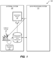
- an example of a signal classification and explanation system 100 comprises an external system 102 and a data processing system 112.
- the external system 102 further comprises a complex system 104, an operational data repository 106, and a monitoring display 108.
- the complex system 104 may be communicatively coupled to the operational data repository 106 for sending a data stream of time series signals 110 from multiple sensors attached to the complex system 104.
- the time series signals 110 may represent multiple data observations collected by the multiple sensors.
- the purpose of the multiple sensors on the complex system 104 is to take measurements at various points within the complex system 104.
- the complex system 104 is a power plant made up of multiple wind turbines that generate energy from the wind, in which case the multiple sensors may include: sensors that measure the rotational speed, sensors that measure vibration at various locations, sensors that measure currents and power for each turbine.
- the complex system 104 may represent a repetitive operation fabrication machine. For each operation multiple sensors capture measurements over time that may include force measurements, position measurements, and current measurements.
- the particular application may include one or more computer classes that generate output, such as log output, for the particular computer application.
- the log output generating classes may be considered built-in instrumentation that reports the current state of multiple classes and objects invoked within the particular computer application.
- the operational data repository 106 may represent a server computer that is configured or programmed to collect the time series signals 110 produced by the multiple sensors on the complex system 104, store the time series signals 110 based on the signal data type, and perform various types of signal processing on the time series signals 110, using one or more stored program that the server computer executes.
- the operational data repository 106 may also be capable of sending either real-time data or stored data to the monitoring display 108 for the purposes of presenting signal data values to a user for monitoring purposes.
- the operational data repository 106 may also aggregate the signal data to create aggregated statistics showing changes in signal values over periods of time.
- Embodiments of the operational data repository 106 features are not limited to the features described above.
- the operational data repository 106 may be implemented using any commercially available monitoring programs and may utilize any monitoring features within the commercially available products.
- the monitoring display 108 may be a computer-implemented machine programmed to display the signal data received from the operational data repository 106.
- the monitoring display 108 may be capable of directly receiving data input from signal data processing system 110.
- the data processing system 112 may be configured to receive a data stream of signal data from the operational data repository 106 and identify physical condi-tions related to the signal data received.
- the data processing system 112 may be further configured to send the identified physical conditions to the external system 102, either by sending data back to the operational data repository 106 or by sending data directly to the monitoring display 108 so that a user can better identify conditions related to the incoming signal data.
- FIG. 2 illustrates additional aspects of the data processing system 112 in one embodiment.
- the data processing system 112 comprises a learning system 202 and a streaming analysis system 208.
- the learning system 202 includes feature learning logic 204 and condition learning logic 206.
- the streaming analysis system 208 includes machine-specific range digest blocks 210 and machine-specific resolver blocks 212.
- the learning system 202 learns to recognize conditions for a particular machine from a historical time range for N signals 216 and known condition episodes 218 of the particular machine.
- the recognized conditions are output to the condition reporting logic 214 of the streaming analysis system 208 as a condition recognition block 224.
- N signal streams 220 for the particular machine are input to the streaming analysis system 208, which applies one of the appropriate machine-specific range digest blocks 210 and machine-specific resolver blocks 212 to determine a streaming condition assessment 222 from the N signal streams 220 and the condition recognition block 224 for the particular machine.
- the streaming condition assessment 222 is applied to operational, recording, and/or display systems.
- the feature learning logic 204 of the learning system 202 uses a multilevel algorithm to create the range digestion block 602 that transforms the historical time range for N signals 216 for a particular machine X for a trailing range [(t - delta) to t] into a time range digest for time t.
- the multilevel approach described below entails determination of an appropriate value of delta, followed by the hierarchical decomposition of the range [(t-delta) to t] into sub-ranges, followed by a hierarchical composition of transformations from the smallest sub-ranges to the largest.
- a digest generation process 700 performs the following actions to create the range digestion block 602:
- the delta size to use at each level of the range digestion process is changed between levels on a logarithmic scale and is not a linear change. Also, in one embodiment, the same delta is used for each signal at a given level. Other embodiments dynamically determine the delta at each level based on specific characteristics of the particular signal being digested.
- a range digestion block generation process 800 then performs the following actions to complete the generation of the range digestion block 602:
- the resolver block 604 is generated and added to the condition recognition block 224 by applying the range digestion block 602 to the supplied historical time range for N signals 216, and the known condition episodes 218 for the historical time range.
- the streaming analysis system 208 uses a combination of unsupervised and supervised learning techniques including clustering, random forest, and nearest neighbors to transform the condition recognition block 224 into a streaming condition assessment 222 for the machine.
- This streaming condition assessment 222 will be one of the following:
- the system then assembles the condition recognition block 224 by composing the range digestion block 602 and the resolver block 604 in series. This results in a transformation in a range of time for the N signals into a sequence of condition values.
- Figure 9 is an example block diagram of a computing device 900 that may incorporate embodiments of the present invention.
- Figure 9 is merely illustrative of a machine system (e.g., data processing system 112) to carry out aspects of the technical processes described herein, and does not limit the scope of the claims.
- the computing device 900 typically includes a monitor or graphical user interface 902, a data processing system 920, a communication network interface 912, input device(s) 908, output device(s) 906, and the like.
- the data processing system 920 may include one or more processor(s) 904 that communicate with a number of peripheral devices via a bus subsystem 918.
- peripheral devices may include input device(s) 908, output device(s) 906, communication network interface 912, and a storage subsystem, such as a volatile memory 910 and a nonvolatile memory 914.
- the volatile memory 910 and/or the nonvolatile memory 914 may store computer-executable instructions and thus forming logic 922 that when applied to and executed by the processor(s) 904 implement embodiments of the analytical and control processes disclosed herein.
- the input device(s) 908 include devices and mechanisms for inputting information to the data processing system 920. These may include a keyboard, a keypad, a touch screen incorporated into the monitor or graphical user interface 902, audio input devices such as voice recognition systems, microphones, and other types of input devices.
- the input device(s) 908 may be embodied as a computer mouse, a trackball, a track pad, a joystick, wireless remote, drawing tablet, voice command system, eye tracking system, and the like.
- the input device(s) 908 typically allow a user to select objects, icons, control areas, text and the like that appear on the monitor or graphical user interface 902 via a command such as a click of a button or the like.
- the output device(s) 906 include devices and mechanisms for outputting information from the data processing system 920. These may include the monitor or graphical user interface 902, speakers, printers, infrared LEDs, and so on as well understood in the art.
- the communication network interface 912 provides an interface to communication networks (e.g., communication network 916) and devices external to the data processing system 920.
- the communication network interface 912 may serve as an interface for receiving data from and transmitting data to other systems.
- Embodiments of the communication network interface 912 may include an Ethernet interface, a modem (telephone, satellite, cable, ISDN), (asynchronous) digital subscriber line (DSL), FireWire, USB, a wireless communication interface such as Bluetooth or WiFi, a near field communication wireless interface, a cellular interface, and the like.
- the communication network interface 912 may be coupled to the communication network 916 via an antenna, a cable, or the like.
- the communication network interface 912 may be physically integrated on a circuit board of the data processing system 920, or in some cases may be implemented in software or firmware, such as "soft modems", or the like.
- the computing device 900 may include logic that enables communications over a network using protocols such as HTTP, TCP/IP, RTP/RTSP, IPX, UDP and the like.
- the volatile memory 910 and the nonvolatile memory 914 are examples of tangible media configured to store computer readable data and instructions to implement various embodiments of the processes described herein.
- Other types of tangible media include removable memory (e.g., pluggable USB memory devices, mobile device SIM cards), optical storage media such as CD-ROMS, DVDs, semiconductor memories such as flash memories, non-transitory read-only-memories (ROMS), battery-backed volatile memories, networked storage devices, and the like.
- the volatile memory 910 and the nonvolatile memory 914 may be configured to store the basic programming and data constructs that provide the functionality of the disclosed processes and other embodiments thereof that fall within the scope of the present invention.
- Logic 922 that implements embodiments of the present invention may be implemented by the volatile memory 910 and/or the nonvolatile memory 914. Said logic 922 may be applied from the volatile memory 910 and/or nonvolatile memory 914 and executed by the processor(s) 904. The volatile memory 910 and the nonvolatile memory 914 may also provide a repository for storing data used by the logic 922.
- the volatile memory 910 and the nonvolatile memory 914 may include a number of memories including a main random access memory (RAM) for storage of instructions and data during program execution and a read only memory (ROM) in which read-only non-transitory instructions are stored.
- the volatile memory 910 and the nonvolatile memory 914 may include a file storage subsystem providing persistent (non-volatile) storage for program and data files.
- the volatile memory 910 and the nonvolatile memory 914 may include removable storage systems, such as removable flash memory.
- the bus subsystem 918 provides a mechanism for enabling the various components and subsystems of data processing system 920 communicate with each other as intended. Although the communication network interface 912 is depicted schematically as a single bus, some embodiments of the bus subsystem 918 may utilize multiple distinct busses.
- the computing device 900 may be a device such as a smartphone, a desktop computer, a laptop computer, a rack-mounted computer system, a computer server, or a tablet computer device. As commonly known in the art, the computing device 900 may be implemented as a collection of multiple networked computing devices. Further, the computing device 900 will typically include operating system logic (not illustrated) the types and nature of which are well known in the art.
- Circuitry in this context refers to electrical circuitry having at least one discrete electrical circuit, electrical circuitry having at least one integrated circuit, electrical circuitry having at least one application specific integrated circuit, circuitry forming a general purpose computing device configured by a computer program (e.g., a general purpose computer configured by a computer program which at least partially carries out processes or devices described herein, or a microprocessor configured by a computer program which at least partially carries out processes or devices described herein), circuitry forming a memory device (e.g., forms of random access memory), or circuitry forming a communications device (e.g., a modem, communications switch, or optical-electrical equipment).
- a computer program e.g., a general purpose computer configured by a computer program which at least partially carries out processes or devices described herein, or a microprocessor configured by a computer program which at least partially carries out processes or devices described herein
- circuitry forming a memory device e.g., forms of random access memory
- Fiberware in this context refers to software logic embodied as processor-executable instructions stored in read-only memories or media.
- Hardware in this context refers to logic embodied as analog or digital circuitry.
- Logic in this context refers to machine memory circuits, non-transitory machine readable media, and/or circuitry which by way of its material and/or material-energy configuration comprises control and/or procedural signals, and/or settings and values (such as resistance, impedance, capacitance, inductance, current/voltage ratings, etc.), that may be applied to influence the operation of a device.
- Magnetic media, electronic circuits, electrical and optical memory (both volatile and nonvolatile), and firmware are examples of logic.
- Logic specifically excludes pure signals or software per se (however does not exclude machine memories comprising software and thereby forming configurations of matter).
- Software in this context refers to logic implemented as processor-executable instructions in a machine memory (e.g. read/write volatile or nonvolatile memory or media).
- references to “one embodiment” or “an embodiment” do not necessarily refer to the same embodiment, although they may.
- the words “comprise,” “comprising,” and the like are to be construed in an inclusive sense as opposed to an exclusive or exhaustive sense; that is to say, in the sense of “including, but not limited to.” Words using the singular or plural number also include the plural or singular number respectively, unless expressly limited to a single one or multiple ones.
- the words “herein,” “above,” “below” and words of similar import when used in this application, refer to this application as a whole and not to any particular portions of this application.
Landscapes
- Engineering & Computer Science (AREA)
- Theoretical Computer Science (AREA)
- Physics & Mathematics (AREA)
- General Physics & Mathematics (AREA)
- Data Mining & Analysis (AREA)
- Evolutionary Computation (AREA)
- Artificial Intelligence (AREA)
- Software Systems (AREA)
- General Engineering & Computer Science (AREA)
- Mathematical Physics (AREA)
- Computing Systems (AREA)
- Computer Vision & Pattern Recognition (AREA)
- Life Sciences & Earth Sciences (AREA)
- Computational Linguistics (AREA)
- Health & Medical Sciences (AREA)
- Biomedical Technology (AREA)
- Biophysics (AREA)
- General Health & Medical Sciences (AREA)
- Molecular Biology (AREA)
- Automation & Control Theory (AREA)
- Medical Informatics (AREA)
- Bioinformatics & Computational Biology (AREA)
- Evolutionary Biology (AREA)
- Bioinformatics & Cheminformatics (AREA)
- Chemical & Material Sciences (AREA)
- Chemical Kinetics & Catalysis (AREA)
- Testing And Monitoring For Control Systems (AREA)
- Image Analysis (AREA)
Description
- Complex operational systems are subject to unexpected changes in condition over time. As a side effect of their operation, these systems produce multiple signals that can be captured. These signals may include currents, temperatures, positions, forces, material properties, etc. Patterns present in these signals may be used to understand the current or future condition of a complex operational system as it is operating. For example, a stamping machine that produces steel parts will periodically enter a condition in which maintenance is required. During operation, measurements of currents, forces, and temperatures are captured, and can be used to identify the onset of a maintenance-needed condition.
Patent application US 2018/173173 discloses a control system for controlling machines that can perform singular spectrum analysis on a time series by: generating a trajectory matrix from the time series, performing singular value decomposition on the trajectory matrix to determine elementary matrices and corresponding eigenvalues, and automatically categorizing the elementary matrices into groups. The matrices is automatically categorized into the groups by: generating a matrix of w-correlation values based on the eigenvalues, categorizing the w-correlation values into a predefined number of w-correlation sets, and forming the groups based on the predefined number of w-correlation sets. The control system can determine component time-series based on the groups, and generate a predictive forecast using the component time-series and can use the predictive forecast to control operation of the machine. - The present invention is set out in the appended set of claims. A system and method are disclosed to recognize operational conditions in diverse and complex machine systems from available signal data. Typical examples of these complex machine systems include batch-oriented machine systems and continuously running machine systems/processes. To accomplish the condition recognition for either batch or continuous machine systems, the system learns features from the raw signal data. These features may then be utilized to classify the condition of the machine system in question. The system includes multi-level feature learning and classification for any kind of systems. The system further analyzes how the state of the system evolves over time.
- The invention may be utilized as a component of a complex machine system, for example for manufacturing or product testing, to improve the efficiency and accuracy of the complex machine system in operation. In this regard, the invention may be utilized as a component of an open loop or closed loop feedback mechanism in such systems, identifying and alerting as to aberrational behavior of specific stations in the complex system, and thus directing personnel to the remediation of the condition, or triggering automatic remediation measures. In some cases, the invention may assert control signals to the aberrational components to automatically 'close the loop' and remediate their behavior. In addition to use with complex machine systems, the invention may also be useful in exercise and fitness monitors, among other things.
- To easily identify the discussion of any particular element or act, the most significant digit or digits in a reference number refer to the figure number in which that element is first introduced.
-
FIG. 1 illustrates an embodiment of a signal classification andexplanation system 100. -
FIG. 2 illustrates more details of the signal classification andexplanation system 100 in accordance with one embodiment. -
FIG. 3 illustrates adigest generation process 300 in accordance with one embodiment. -
FIG. 4 illustrates a multi-levelrange digestion process 400 in accordance with one embodiment. -
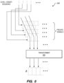
FIG. 5 illustrates apseudo-signal transformation process 500 in accordance with one embodiment. -
FIG. 6 illustrates aprocess 600 for forming acondition recognition block 224 in accordance with one embodiment. -
FIG. 7 illustrates adigest generation process 700 in accordance with one embodiment. -
FIG. 8 illustrates a range digestionblock generation process 800 in accordance with one embodiment. -
FIG. 9 is an example block diagram of acomputing device 900 that may incorporate embodiments of the present invention. - Various terminology is utilized herein and should be accorded its ordinary meaning in the arts unless otherwise indicated expressly or by context.
- "Digest" refers to a set of values used to represent signal behavior for a trailing period of time.
- "Condition" refers to the state or status of the machine as it evolves over time.
- "Block" refers to logic having a boundary defining the contents of the block, such that the contents may be manipulated (e.g., communicated, copied, organized) as a unit. Examples of blocks are files, classes, tables, databases, and data structures.
- The system disclosed herein learns patterns in the sets of signals produced during operation of a complex system and combines learned patterns with records of past conditions (known condition episodes) to learn how to recognize the condition of the machine while it operates over time. For example, as a station in a complex system is utilized to produce a part, it repetitively executes a particular operation. During each stage, various quantities such as currents or forces are measured and captured in the form of a time varying signal. Over time, the operating condition of the station may degrade or change in unexpected ways, leading to necessity for a maintenance intervention to prevent downtime or other loss. Knowledge of the operating condition on a continuous basis enhances the ability of the operators of the machine to achieve performance goals. The system disclosed herein identifies patterns in the sets of signals produced during operation of a complex system and combines the identified patterns with records of past conditions to:
- 1. Predict the condition of the complex system while it operates; and/or
- 2. Predict a quality outcome of a product produced by the system;
- In general, operation of a machine produces N time series signal traces. Each trace represents the capture of a sequence of measurements for that signal over time. Measurements can be captured at different and irregular intervals across the signals. In addition to signal data, operational data systems can capture maintenance events, quality measures, and performance metrics that can characterize periods of known condition for the machine.
- Referring to
Figure 1 , an example of a signal classification andexplanation system 100 comprises anexternal system 102 and adata processing system 112. Theexternal system 102 further comprises a complex system 104, anoperational data repository 106, and amonitoring display 108. - The complex system 104 may be communicatively coupled to the
operational data repository 106 for sending a data stream oftime series signals 110 from multiple sensors attached to the complex system 104. Thetime series signals 110 may represent multiple data observations collected by the multiple sensors. The purpose of the multiple sensors on the complex system 104 is to take measurements at various points within the complex system 104. - One example of the complex system 104 is a power plant made up of multiple wind turbines that generate energy from the wind, in which case the multiple sensors may include: sensors that measure the rotational speed, sensors that measure vibration at various locations, sensors that measure currents and power for each turbine. In another example, the complex system 104 may represent a repetitive operation fabrication machine. For each operation multiple sensors capture measurements over time that may include force measurements, position measurements, and current measurements. The particular application may include one or more computer classes that generate output, such as log output, for the particular computer application. The log output generating classes may be considered built-in instrumentation that reports the current state of multiple classes and objects invoked within the particular computer application.
- In an embodiment, the
operational data repository 106 may represent a server computer that is configured or programmed to collect thetime series signals 110 produced by the multiple sensors on the complex system 104, store thetime series signals 110 based on the signal data type, and perform various types of signal processing on thetime series signals 110, using one or more stored program that the server computer executes. Theoperational data repository 106 may also be capable of sending either real-time data or stored data to themonitoring display 108 for the purposes of presenting signal data values to a user for monitoring purposes. Theoperational data repository 106 may also aggregate the signal data to create aggregated statistics showing changes in signal values over periods of time. Embodiments of theoperational data repository 106 features are not limited to the features described above. Theoperational data repository 106 may be implemented using any commercially available monitoring programs and may utilize any monitoring features within the commercially available products. - The
monitoring display 108 may be a computer-implemented machine programmed to display the signal data received from theoperational data repository 106. Themonitoring display 108 may be capable of directly receiving data input from signaldata processing system 110. - The
data processing system 112 may be configured to receive a data stream of signal data from theoperational data repository 106 and identify physical condi-tions related to the signal data received. Thedata processing system 112 may be further configured to send the identified physical conditions to theexternal system 102, either by sending data back to theoperational data repository 106 or by sending data directly to themonitoring display 108 so that a user can better identify conditions related to the incoming signal data. -
Figure 2 illustrates additional aspects of thedata processing system 112 in one embodiment. Thedata processing system 112 comprises alearning system 202 and astreaming analysis system 208. Thelearning system 202 includesfeature learning logic 204 andcondition learning logic 206. Thestreaming analysis system 208 includes machine-specific range digestblocks 210 and machine-specific resolver blocks 212. Thelearning system 202 learns to recognize conditions for a particular machine from a historical time range for N signals 216 andknown condition episodes 218 of the particular machine. The recognized conditions are output to thecondition reporting logic 214 of thestreaming analysis system 208 as acondition recognition block 224. During operation, N signal streams 220 for the particular machine are input to thestreaming analysis system 208, which applies one of the appropriate machine-specific range digestblocks 210 and machine-specific resolver blocks 212 to determine astreaming condition assessment 222 from the N signal streams 220 and thecondition recognition block 224 for the particular machine. Thestreaming condition assessment 222 is applied to operational, recording, and/or display systems. - Referring now to
Figure 3 - Figure 8 , thecondition recognition block 224 is created by thelearning system 202 and is, according to the present invention, comprised of arange digestion block 602 that transforms incoming signal data in a time range [(t - delta) to t] into a range digest for time t, and aresolver block 604 that transforms a range digest for time t into a condition value for time to where to >= t. - The
feature learning logic 204 of thelearning system 202 uses a multilevel algorithm to create therange digestion block 602 that transforms the historical time range for N signals 216 for a particular machine X for a trailing range [(t - delta) to t] into a time range digest for time t. The multilevel approach described below entails determination of an appropriate value of delta, followed by the hierarchical decomposition of the range [(t-delta) to t] into sub-ranges, followed by a hierarchical composition of transformations from the smallest sub-ranges to the largest. Referring toFigure 7 , a digestgeneration process 700 performs the following actions to create the range digestion block 602: - 1. Determine an appropriate top-level evaluation range (top level delta) for each signal (block 702). This range captures a pragmatic period of trailing history that can accurately characterize the behavior of the historical time range for N signals 216 over time. The range is determined through signal-by-signal analysis of the provided historical time range for N signals 216 using numerical optimization techniques such as entropy minimization in combination with user provided hints (such as upper and lower bounds on time ranges or on the number of repetitive operations that a machine may execute).
- 2. Hierarchically decompose the chosen top-level range for each signal into n -1 progressively smaller sub-ranges (intermediate delta values, block 704) until one of the sub-ranges (the "base range", herein delta0) meets computational efficiency criteria (decision block 706) that are based on the number of signals, sample rates per signal, and available computational resources. Sub-ranges are determined through numerical optimization techniques such as entropy minimization in combination with user provided hints (such as upper and lower bounds on time ranges or on the number of repetitive operations that a machine may execute).
- 3. For each signal, step the base range window across the signal, and for each step of the base range window, apply a
range digestor 302 to generate a transformation (block 708) that maps the sequence of raw signal values in the base range window [ti - delta0 to ti ] into a digest for the signal at time ti. This process is illustrated by thedigest generation process 300 isFigure 3 forlevel 0. If there are M base ranges in the top-level range for a particular signal, this will generate M0 level 0 digests for the signal. The transformation can be generated by a variety of techniques including independent component analysis (ICA) or long short-term memory (LSTM) recurrent neural networks using the provided historical range of data for each signal to train a transformation. - In one embodiment, the delta size to use at each level of the range digestion process is changed between levels on a logarithmic scale and is not a linear change. Also, in one embodiment, the same delta is used for each signal at a given level. Other embodiments dynamically determine the delta at each level based on specific characteristics of the particular signal being digested.
- Referring now to
Figure 8 , a range digestionblock generation process 800 then performs the following actions to complete the generation of the range digestion block 602: - 1. For each level j of the n-1 levels of range decomposition of a signal above the base range level:
- a. The range digestion is applied (block 802) sequentially to the historical signal time series signal data over i windows each having a range [ti - deltaj to ti], i = 0 to Mj-l, where deltaj is the delta to use for level j of the decomposition. See the multi-level
range digestion process 400 inFigure 4 . This forms a sequence of Mj of range digests for each signal at level j, one for each time ti corresponding to a range of deltaj raw data signals. These Mj range digests are referred to herein as the set of pseudo-signals for level j. Note that the value of Mj varies from level to level. - b. A
transformer 502 is applied on the Mj range digests of level j using each of the pseudo-signals (block 804) for level j (see thepseudo-signal transformation process 500 inFigure 5 ). This transformation generates the range transformation block Bj for level j. Thetransformer 502 can utilize a variety of techniques including independent component analysis (ICA) or long short-term memory (LSTM) using the provided historical range of data to train thetransformer 502.
- a. The range digestion is applied (block 802) sequentially to the historical signal time series signal data over i windows each having a range [ti - deltaj to ti], i = 0 to Mj-l, where deltaj is the delta to use for level j of the decomposition. See the multi-level
- 2. The composed sequence of range transformation blocks βj for
level 0 to the top-level n-1 (see theprocess 600 inFigure 6 ) for each signal is the range digestion block 602 (block 806). This block maps a time range [t-deltan-1 to t] of the historical time range for N signals 216 to a combined digest for the signals at time t. - Next the
resolver block 604 is generated and added to thecondition recognition block 224 by applying therange digestion block 602 to the supplied historical time range for N signals 216, and theknown condition episodes 218 for the historical time range. Thestreaming analysis system 208 uses a combination of unsupervised and supervised learning techniques including clustering, random forest, and nearest neighbors to transform thecondition recognition block 224 into astreaming condition assessment 222 for the machine. Thisstreaming condition assessment 222 will be one of the following: - a. One of the known condition labels among the set of provided episodes.
- b. An auto-generated "unlabledX" label that denotes a discovered condition for which no known condition episodes were provided.
- c. The "unknown" condition that denotes a condition not seen previously or an anomaly.
- The system then assembles the
condition recognition block 224 by composing therange digestion block 602 and theresolver block 604 in series. This results in a transformation in a range of time for the N signals into a sequence of condition values. -
Figure 9 is an example block diagram of acomputing device 900 that may incorporate embodiments of the present invention.Figure 9 is merely illustrative of a machine system (e.g., data processing system 112) to carry out aspects of the technical processes described herein, and does not limit the scope of the claims. One of ordinary skill in the art would recognize other variations, modifications, and alternatives. In one embodiment, thecomputing device 900 typically includes a monitor orgraphical user interface 902, adata processing system 920, acommunication network interface 912, input device(s) 908, output device(s) 906, and the like. - As depicted in
Figure 9 , thedata processing system 920 may include one or more processor(s) 904 that communicate with a number of peripheral devices via abus subsystem 918. These peripheral devices may include input device(s) 908, output device(s) 906,communication network interface 912, and a storage subsystem, such as avolatile memory 910 and anonvolatile memory 914. - The
volatile memory 910 and/or thenonvolatile memory 914 may store computer-executable instructions and thus forminglogic 922 that when applied to and executed by the processor(s) 904 implement embodiments of the analytical and control processes disclosed herein. - The input device(s) 908 include devices and mechanisms for inputting information to the
data processing system 920. These may include a keyboard, a keypad, a touch screen incorporated into the monitor orgraphical user interface 902, audio input devices such as voice recognition systems, microphones, and other types of input devices. In various embodiments, the input device(s) 908 may be embodied as a computer mouse, a trackball, a track pad, a joystick, wireless remote, drawing tablet, voice command system, eye tracking system, and the like. The input device(s) 908 typically allow a user to select objects, icons, control areas, text and the like that appear on the monitor orgraphical user interface 902 via a command such as a click of a button or the like. - The output device(s) 906 include devices and mechanisms for outputting information from the
data processing system 920. These may include the monitor orgraphical user interface 902, speakers, printers, infrared LEDs, and so on as well understood in the art. - The
communication network interface 912 provides an interface to communication networks (e.g., communication network 916) and devices external to thedata processing system 920. Thecommunication network interface 912 may serve as an interface for receiving data from and transmitting data to other systems. Embodiments of thecommunication network interface 912 may include an Ethernet interface, a modem (telephone, satellite, cable, ISDN), (asynchronous) digital subscriber line (DSL), FireWire, USB, a wireless communication interface such as Bluetooth or WiFi, a near field communication wireless interface, a cellular interface, and the like. - The
communication network interface 912 may be coupled to thecommunication network 916 via an antenna, a cable, or the like. In some embodiments, thecommunication network interface 912 may be physically integrated on a circuit board of thedata processing system 920, or in some cases may be implemented in software or firmware, such as "soft modems", or the like. - The
computing device 900 may include logic that enables communications over a network using protocols such as HTTP, TCP/IP, RTP/RTSP, IPX, UDP and the like. - The
volatile memory 910 and thenonvolatile memory 914 are examples of tangible media configured to store computer readable data and instructions to implement various embodiments of the processes described herein. Other types of tangible media include removable memory (e.g., pluggable USB memory devices, mobile device SIM cards), optical storage media such as CD-ROMS, DVDs, semiconductor memories such as flash memories, non-transitory read-only-memories (ROMS), battery-backed volatile memories, networked storage devices, and the like. Thevolatile memory 910 and thenonvolatile memory 914 may be configured to store the basic programming and data constructs that provide the functionality of the disclosed processes and other embodiments thereof that fall within the scope of the present invention. -
Logic 922 that implements embodiments of the present invention may be implemented by thevolatile memory 910 and/or thenonvolatile memory 914.Said logic 922 may be applied from thevolatile memory 910 and/ornonvolatile memory 914 and executed by the processor(s) 904. Thevolatile memory 910 and thenonvolatile memory 914 may also provide a repository for storing data used by thelogic 922. - The
volatile memory 910 and thenonvolatile memory 914 may include a number of memories including a main random access memory (RAM) for storage of instructions and data during program execution and a read only memory (ROM) in which read-only non-transitory instructions are stored. Thevolatile memory 910 and thenonvolatile memory 914 may include a file storage subsystem providing persistent (non-volatile) storage for program and data files. Thevolatile memory 910 and thenonvolatile memory 914 may include removable storage systems, such as removable flash memory. - The
bus subsystem 918 provides a mechanism for enabling the various components and subsystems ofdata processing system 920 communicate with each other as intended. Although thecommunication network interface 912 is depicted schematically as a single bus, some embodiments of thebus subsystem 918 may utilize multiple distinct busses. - It will be readily apparent to one of ordinary skill in the art that the
computing device 900 may be a device such as a smartphone, a desktop computer, a laptop computer, a rack-mounted computer system, a computer server, or a tablet computer device. As commonly known in the art, thecomputing device 900 may be implemented as a collection of multiple networked computing devices. Further, thecomputing device 900 will typically include operating system logic (not illustrated) the types and nature of which are well known in the art. - Terms used herein should be accorded their ordinary meaning in the relevant arts, or the meaning indicated by their use in context, but if an express definition is provided, that meaning controls.
- "Circuitry" in this context refers to electrical circuitry having at least one discrete electrical circuit, electrical circuitry having at least one integrated circuit, electrical circuitry having at least one application specific integrated circuit, circuitry forming a general purpose computing device configured by a computer program (e.g., a general purpose computer configured by a computer program which at least partially carries out processes or devices described herein, or a microprocessor configured by a computer program which at least partially carries out processes or devices described herein), circuitry forming a memory device (e.g., forms of random access memory), or circuitry forming a communications device (e.g., a modem, communications switch, or optical-electrical equipment).
- "Firmware" in this context refers to software logic embodied as processor-executable instructions stored in read-only memories or media.
- "Hardware" in this context refers to logic embodied as analog or digital circuitry.
- "Logic" in this context refers to machine memory circuits, non-transitory machine readable media, and/or circuitry which by way of its material and/or material-energy configuration comprises control and/or procedural signals, and/or settings and values (such as resistance, impedance, capacitance, inductance, current/voltage ratings, etc.), that may be applied to influence the operation of a device. Magnetic media, electronic circuits, electrical and optical memory (both volatile and nonvolatile), and firmware are examples of logic. Logic specifically excludes pure signals or software per se (however does not exclude machine memories comprising software and thereby forming configurations of matter).
- "Software" in this context refers to logic implemented as processor-executable instructions in a machine memory (e.g. read/write volatile or nonvolatile memory or media).
- Herein, references to "one embodiment" or "an embodiment" do not necessarily refer to the same embodiment, although they may. Unless the context clearly requires otherwise, throughout the description and the claims, the words "comprise," "comprising," and the like are to be construed in an inclusive sense as opposed to an exclusive or exhaustive sense; that is to say, in the sense of "including, but not limited to." Words using the singular or plural number also include the plural or singular number respectively, unless expressly limited to a single one or multiple ones. Additionally, the words "herein," "above," "below" and words of similar import, when used in this application, refer to this application as a whole and not to any particular portions of this application. When the claims use the word "or" in reference to a list of two or more items, that word covers all of the following interpretations of the word: any of the items in the list, all of the items in the list and any combination of the items in the list, unless expressly limited to one or the other. Any terms not expressly defined herein have their conventional meaning as commonly understood by those having skill in the relevant art(s).
Claims (11)
- A method comprising:receiving a plurality of time series signals (110) generated by a plurality of sensors of one or more machines;characterized in that the method further comprises:
for a top-level evaluation range ending at a certain time and for each signal of the plurality of time series signals (702):identifying a base range transformation window for the signal through an iterative process of range reduction, each iteration corresponding to a level and a level range (704, 706);for each level:transforming the signal (110) into a plurality of digests using the corresponding level range, each digest including a set of values representing signal behavior for a trailing period of time (708, 302); andinputting the digests for each level as pseudo time-series signals to a transformer (502) to generate a transformation block for the level;composing the transformation blocks for the levels into a range digestion block (602) for the certain time, the range digestion block (602, 806) transforming incoming signal data for a time range ending at the certain time into a range digest for the certain time;generating a resolver block (604) from the range digestion block (602, 806) and known condition episodes, the resolver block (604) configured to transform a given range digest for a given time into a condition value for the given or a later time;composing a condition recognition block (224) from the range digestion block (602) and the resolver block (604); andapplying a combination of unsupervised and supervised learning to transform the condition recognition block (224) into a feedback signal applied to the or more machines. - The method according to claim 1, wherein the feedback signal comprises one of the following:a label of one of the known condition episodes;an auto-generated label that denotes a discovered condition not matching one of the known condition episodes; andan unknown condition denoting a condition not encountered previously, or an anomaly.
- The method according to claim 1, wherein the condition recognition block (224) is composed by arranging the range digestion block (602) and the resolver block (604) in series.
- The method according to claim 1, wherein the combination of unsupervised and supervised learning techniques comprises clustering, random forest, and nearest-neighbors transformations.
- The method according to claim 1, wherein the transformer (502) utilizes one or more of independent component analysis (ICA) and long short-term memory (LSTM).
- The method according to claim 1, wherein the level range to utilize to generate the plurality of digests at each level is varied between levels on a logarithmic scale.
- The method according to claim 1, wherein the same set of level ranges is used for each signal (110).
- The method according to claim 1, wherein the set of level ranges is dynamically determined for each signal (110) based on specific characteristics of the signal (100) being digested.
- The method according to claim 1, wherein identifying the base range transformation window for the signal (110) through an iterative process of range reduction comprises decomposing the top-level evaluation range into sub-ranges (704), until one of the sub-ranges meets computational efficiency criteria.
- The method according to claim 9, wherein the computational efficiency criteria are based on a number of signals (110), sample rates per signal, and available computational resources.
- The method according to claim 9, wherein the sub-ranges are determined through numerical optimization techniques such as entropy minimization in combination with user provided hints.
Applications Claiming Priority (2)
| Application Number | Priority Date | Filing Date | Title |
|---|---|---|---|
| US16/042,881 US10635984B2 (en) | 2018-07-23 | 2018-07-23 | System and method for the assessment of condition in complex operational systems based on multi-level pattern recognition |
| PCT/US2019/034628 WO2020023111A1 (en) | 2018-07-23 | 2019-05-30 | System and method for the assessment of condition in complex operational systems based on multi-level pattern recognition |
Publications (4)
| Publication Number | Publication Date |
|---|---|
| EP3827382A1 EP3827382A1 (en) | 2021-06-02 |
| EP3827382A4 EP3827382A4 (en) | 2022-04-20 |
| EP3827382B1 true EP3827382B1 (en) | 2023-09-20 |
| EP3827382B8 EP3827382B8 (en) | 2023-10-25 |
Family
ID=69162967
Family Applications (1)
| Application Number | Title | Priority Date | Filing Date |
|---|---|---|---|
| EP19840662.1A Active EP3827382B8 (en) | 2018-07-23 | 2019-05-30 | System and method for the assessment of condition in complex operational systems based on multi-level pattern recognition |
Country Status (4)
| Country | Link |
|---|---|
| US (1) | US10635984B2 (en) |
| EP (1) | EP3827382B8 (en) |
| JP (1) | JP7004866B2 (en) |
| WO (1) | WO2020023111A1 (en) |
Families Citing this family (2)
| Publication number | Priority date | Publication date | Assignee | Title |
|---|---|---|---|---|
| JP7184636B2 (en) * | 2018-12-27 | 2022-12-06 | 三菱重工業株式会社 | Data sorting device and method, and monitoring diagnostic device |
| EP4095636A3 (en) * | 2021-05-23 | 2023-01-25 | 3D Signals | Pattern recognition for part manufacturing processes |
Family Cites Families (12)
| Publication number | Priority date | Publication date | Assignee | Title |
|---|---|---|---|---|
| US5440661A (en) * | 1990-01-31 | 1995-08-08 | The United States Of America As Represented By The United States Department Of Energy | Time series association learning |
| JP2001285073A (en) * | 2000-03-29 | 2001-10-12 | Sony Corp | Signal processing apparatus and method |
| US8090161B2 (en) | 2006-06-19 | 2012-01-03 | Christiane Kaplan | Systems and method for signature verification |
| US8175941B2 (en) * | 2007-11-19 | 2012-05-08 | Codestreet, Llc | Method and system for developing and applying market data scenarios |
| WO2010026839A1 (en) * | 2008-09-04 | 2010-03-11 | 独立行政法人科学技術振興機構 | Video signal converting system |
| KR102223419B1 (en) * | 2013-06-14 | 2021-03-04 | 마이크로소프트 테크놀로지 라이센싱, 엘엘씨 | Fast grouping of time series |
| US10409926B2 (en) * | 2013-11-27 | 2019-09-10 | Falkonry Inc. | Learning expected operational behavior of machines from generic definitions and past behavior |
| US10037128B2 (en) * | 2014-02-04 | 2018-07-31 | Falkonry, Inc. | Operating behavior classification interface |
| US10552762B2 (en) * | 2015-07-16 | 2020-02-04 | Falkonry Inc. | Machine learning of physical conditions based on abstract relations and sparse labels |
| US10282361B2 (en) | 2016-04-29 | 2019-05-07 | Salesforce.Com, Inc. | Transforming time series data points from concurrent processes |
| WO2018075400A1 (en) * | 2016-10-19 | 2018-04-26 | Sas Institute Inc. | Advanced control systems for machines |
| JP6675014B2 (en) * | 2016-11-30 | 2020-04-01 | 株式会社日立製作所 | Data collection system, abnormality detection method, and gateway device |
-
2018
- 2018-07-23 US US16/042,881 patent/US10635984B2/en active Active
-
2019
- 2019-05-30 JP JP2021503902A patent/JP7004866B2/en active Active
- 2019-05-30 WO PCT/US2019/034628 patent/WO2020023111A1/en not_active Ceased
- 2019-05-30 EP EP19840662.1A patent/EP3827382B8/en active Active
Also Published As
| Publication number | Publication date |
|---|---|
| EP3827382B8 (en) | 2023-10-25 |
| JP2021524644A (en) | 2021-09-13 |
| EP3827382A4 (en) | 2022-04-20 |
| WO2020023111A1 (en) | 2020-01-30 |
| US10635984B2 (en) | 2020-04-28 |
| EP3827382A1 (en) | 2021-06-02 |
| JP7004866B2 (en) | 2022-01-21 |
| US20200027011A1 (en) | 2020-01-23 |
Similar Documents
| Publication | Publication Date | Title |
|---|---|---|
| CN119336650B (en) | Cross-platform compatibility automatic test method | |
| Helbing et al. | Deep Learning for fault detection in wind turbines | |
| Mohan et al. | Deep power: Deep learning architectures for power quality disturbances classification | |
| US11675643B2 (en) | Method and device for determining a technical incident risk value in a computing infrastructure from performance indicator values | |
| Beghoura et al. | Green software requirements and measurement: random decision forests-based software energy consumption profiling | |
| Wu et al. | Combining OC-SVMs with LSTM for detecting anomalies in telemetry data with irregular intervals | |
| CN119622538A (en) | Equipment status perception system based on peak-shifting and dangerous situation perception | |
| CN118502398B (en) | Intelligent household appliance fault automatic diagnosis and closed loop system and method based on big data | |
| WO2020026442A1 (en) | Event monitoring apparatus, method and program recording medium | |
| CN118536609B (en) | A method and system for configuring an intelligent rule engine | |
| KR102383675B1 (en) | Anomaly detection system of time-series data | |
| Krishnaswamy et al. | Data-driven learning to predict wan network traffic | |
| US10635984B2 (en) | System and method for the assessment of condition in complex operational systems based on multi-level pattern recognition | |
| CN118884095B (en) | Early warning methods, systems, equipment and media for potential safety hazards of equipment electricity use | |
| US11972178B2 (en) | System and method for explanation of condition predictions in complex systems | |
| KR20240135273A (en) | Generative adversarial autoencoder based anomaly detection device exploiting time-frequency feature and method thereof | |
| Verdone et al. | A data attribution approach for unsupervised anomaly detection on multivariate time series | |
| CN119720054B (en) | Factory equipment operation data analysis and anomaly detection system based on machine learning | |
| CN120407000A (en) | A cloud platform operation and maintenance method and system | |
| CN119377038A (en) | Application monitoring method, device, equipment, storage medium and product | |
| WO2025106010A1 (en) | System and method for discovering anomalous construct via cognitive abstraction in a multimodal sensory fusion ecosystem | |
| CN117494896A (en) | Photovoltaic power short-term prediction method and system based on Gaussian mixture model clustering | |
| Chiam et al. | Power quality disturbance classification using transformer network | |
| CN119727635B (en) | Dynamic management system of power amplifier | |
| CN121500785B (en) | Quincuncial contact regulation and control method and system for circuit breaker handcart |
Legal Events
| Date | Code | Title | Description |
|---|---|---|---|
| STAA | Information on the status of an ep patent application or granted ep patent |
Free format text: STATUS: THE INTERNATIONAL PUBLICATION HAS BEEN MADE |
|
| PUAI | Public reference made under article 153(3) epc to a published international application that has entered the european phase |
Free format text: ORIGINAL CODE: 0009012 |
|
| STAA | Information on the status of an ep patent application or granted ep patent |
Free format text: STATUS: REQUEST FOR EXAMINATION WAS MADE |
|
| 17P | Request for examination filed |
Effective date: 20210215 |
|
| AK | Designated contracting states |
Kind code of ref document: A1 Designated state(s): AL AT BE BG CH CY CZ DE DK EE ES FI FR GB GR HR HU IE IS IT LI LT LU LV MC MK MT NL NO PL PT RO RS SE SI SK SM TR |
|
| DAV | Request for validation of the european patent (deleted) | ||
| DAX | Request for extension of the european patent (deleted) | ||
| A4 | Supplementary search report drawn up and despatched |
Effective date: 20220317 |
|
| RIC1 | Information provided on ipc code assigned before grant |
Ipc: G06K 9/62 20060101ALI20220311BHEP Ipc: G05B 23/02 20060101ALI20220311BHEP Ipc: G06K 9/00 20060101ALI20220311BHEP Ipc: G06V 10/82 20220101ALI20220311BHEP Ipc: G06N 3/04 20060101ALI20220311BHEP Ipc: G06N 20/00 20190101AFI20220311BHEP |
|
| REG | Reference to a national code |
Ref country code: DE Ref legal event code: R079 Free format text: PREVIOUS MAIN CLASS: G06N0020000000 Ipc: G05B0023020000 Ref document number: 602019037950 Country of ref document: DE |
|
| GRAP | Despatch of communication of intention to grant a patent |
Free format text: ORIGINAL CODE: EPIDOSNIGR1 |
|
| STAA | Information on the status of an ep patent application or granted ep patent |
Free format text: STATUS: GRANT OF PATENT IS INTENDED |
|
| RIC1 | Information provided on ipc code assigned before grant |
Ipc: G06N 3/044 20230101ALI20230310BHEP Ipc: G06F 18/2413 20230101ALI20230310BHEP Ipc: G06F 18/2134 20230101ALI20230310BHEP Ipc: G06N 20/00 20190101ALI20230310BHEP Ipc: G05B 23/02 20060101AFI20230310BHEP |
|
| INTG | Intention to grant announced |
Effective date: 20230403 |
|
| GRAS | Grant fee paid |
Free format text: ORIGINAL CODE: EPIDOSNIGR3 |
|
| GRAA | (expected) grant |
Free format text: ORIGINAL CODE: 0009210 |
|
| STAA | Information on the status of an ep patent application or granted ep patent |
Free format text: STATUS: THE PATENT HAS BEEN GRANTED |
|
| AK | Designated contracting states |
Kind code of ref document: B1 Designated state(s): AL AT BE BG CH CY CZ DE DK EE ES FI FR GB GR HR HU IE IS IT LI LT LU LV MC MK MT NL NO PL PT RO RS SE SI SK SM TR |
|
| REG | Reference to a national code |
Ref country code: GB Ref legal event code: FG4D |
|
| REG | Reference to a national code |
Ref country code: CH Ref legal event code: PK Free format text: BERICHTIGUNG B8 Ref country code: CH Ref legal event code: PK Free format text: BERICHTIGUNGEN Ref country code: CH Ref legal event code: EP |
|
| REG | Reference to a national code |
Ref country code: DE Ref legal event code: R081 Ref document number: 602019037950 Country of ref document: DE Owner name: FALKONRY INC., CUPERTINO, US Free format text: FORMER OWNER: FALKONRY, INC., SUNNYVALE, CA, US |
|
| REG | Reference to a national code |
Ref country code: DE Ref legal event code: R096 Ref document number: 602019037950 Country of ref document: DE |
|
| REG | Reference to a national code |
Ref country code: IE Ref legal event code: FG4D |
|
| RAP4 | Party data changed (patent owner data changed or rights of a patent transferred) |
Owner name: FALKONRY, INC. |
|
| RIN2 | Information on inventor provided after grant (corrected) |
Inventor name: KEARNS, DAN Inventor name: SUBRAMANIAN, LENIN KUMAR Inventor name: MEHTA, NIKUNJ Inventor name: OLSEN, GREGORY |
|
| P01 | Opt-out of the competence of the unified patent court (upc) registered |
Effective date: 20231009 |
|
| REG | Reference to a national code |
Ref country code: LT Ref legal event code: MG9D |
|
| PG25 | Lapsed in a contracting state [announced via postgrant information from national office to epo] |
Ref country code: GR Free format text: LAPSE BECAUSE OF FAILURE TO SUBMIT A TRANSLATION OF THE DESCRIPTION OR TO PAY THE FEE WITHIN THE PRESCRIBED TIME-LIMIT Effective date: 20231221 |
|
| REG | Reference to a national code |
Ref country code: NL Ref legal event code: MP Effective date: 20230920 |
|
| PG25 | Lapsed in a contracting state [announced via postgrant information from national office to epo] |
Ref country code: SE Free format text: LAPSE BECAUSE OF FAILURE TO SUBMIT A TRANSLATION OF THE DESCRIPTION OR TO PAY THE FEE WITHIN THE PRESCRIBED TIME-LIMIT Effective date: 20230920 Ref country code: RS Free format text: LAPSE BECAUSE OF FAILURE TO SUBMIT A TRANSLATION OF THE DESCRIPTION OR TO PAY THE FEE WITHIN THE PRESCRIBED TIME-LIMIT Effective date: 20230920 Ref country code: NO Free format text: LAPSE BECAUSE OF FAILURE TO SUBMIT A TRANSLATION OF THE DESCRIPTION OR TO PAY THE FEE WITHIN THE PRESCRIBED TIME-LIMIT Effective date: 20231220 Ref country code: LV Free format text: LAPSE BECAUSE OF FAILURE TO SUBMIT A TRANSLATION OF THE DESCRIPTION OR TO PAY THE FEE WITHIN THE PRESCRIBED TIME-LIMIT Effective date: 20230920 Ref country code: LT Free format text: LAPSE BECAUSE OF FAILURE TO SUBMIT A TRANSLATION OF THE DESCRIPTION OR TO PAY THE FEE WITHIN THE PRESCRIBED TIME-LIMIT Effective date: 20230920 Ref country code: HR Free format text: LAPSE BECAUSE OF FAILURE TO SUBMIT A TRANSLATION OF THE DESCRIPTION OR TO PAY THE FEE WITHIN THE PRESCRIBED TIME-LIMIT Effective date: 20230920 Ref country code: GR Free format text: LAPSE BECAUSE OF FAILURE TO SUBMIT A TRANSLATION OF THE DESCRIPTION OR TO PAY THE FEE WITHIN THE PRESCRIBED TIME-LIMIT Effective date: 20231221 Ref country code: FI Free format text: LAPSE BECAUSE OF FAILURE TO SUBMIT A TRANSLATION OF THE DESCRIPTION OR TO PAY THE FEE WITHIN THE PRESCRIBED TIME-LIMIT Effective date: 20230920 |
|
| REG | Reference to a national code |
Ref country code: AT Ref legal event code: MK05 Ref document number: 1613879 Country of ref document: AT Kind code of ref document: T Effective date: 20230920 |
|
| PG25 | Lapsed in a contracting state [announced via postgrant information from national office to epo] |
Ref country code: NL Free format text: LAPSE BECAUSE OF FAILURE TO SUBMIT A TRANSLATION OF THE DESCRIPTION OR TO PAY THE FEE WITHIN THE PRESCRIBED TIME-LIMIT Effective date: 20230920 |
|
| PG25 | Lapsed in a contracting state [announced via postgrant information from national office to epo] |
Ref country code: IS Free format text: LAPSE BECAUSE OF FAILURE TO SUBMIT A TRANSLATION OF THE DESCRIPTION OR TO PAY THE FEE WITHIN THE PRESCRIBED TIME-LIMIT Effective date: 20240120 |
|
| PG25 | Lapsed in a contracting state [announced via postgrant information from national office to epo] |
Ref country code: AT Free format text: LAPSE BECAUSE OF FAILURE TO SUBMIT A TRANSLATION OF THE DESCRIPTION OR TO PAY THE FEE WITHIN THE PRESCRIBED TIME-LIMIT Effective date: 20230920 |
|
| PG25 | Lapsed in a contracting state [announced via postgrant information from national office to epo] |
Ref country code: ES Free format text: LAPSE BECAUSE OF FAILURE TO SUBMIT A TRANSLATION OF THE DESCRIPTION OR TO PAY THE FEE WITHIN THE PRESCRIBED TIME-LIMIT Effective date: 20230920 |
|
| PG25 | Lapsed in a contracting state [announced via postgrant information from national office to epo] |
Ref country code: SM Free format text: LAPSE BECAUSE OF FAILURE TO SUBMIT A TRANSLATION OF THE DESCRIPTION OR TO PAY THE FEE WITHIN THE PRESCRIBED TIME-LIMIT Effective date: 20230920 Ref country code: RO Free format text: LAPSE BECAUSE OF FAILURE TO SUBMIT A TRANSLATION OF THE DESCRIPTION OR TO PAY THE FEE WITHIN THE PRESCRIBED TIME-LIMIT Effective date: 20230920 Ref country code: IS Free format text: LAPSE BECAUSE OF FAILURE TO SUBMIT A TRANSLATION OF THE DESCRIPTION OR TO PAY THE FEE WITHIN THE PRESCRIBED TIME-LIMIT Effective date: 20240120 Ref country code: ES Free format text: LAPSE BECAUSE OF FAILURE TO SUBMIT A TRANSLATION OF THE DESCRIPTION OR TO PAY THE FEE WITHIN THE PRESCRIBED TIME-LIMIT Effective date: 20230920 Ref country code: EE Free format text: LAPSE BECAUSE OF FAILURE TO SUBMIT A TRANSLATION OF THE DESCRIPTION OR TO PAY THE FEE WITHIN THE PRESCRIBED TIME-LIMIT Effective date: 20230920 Ref country code: CZ Free format text: LAPSE BECAUSE OF FAILURE TO SUBMIT A TRANSLATION OF THE DESCRIPTION OR TO PAY THE FEE WITHIN THE PRESCRIBED TIME-LIMIT Effective date: 20230920 Ref country code: AT Free format text: LAPSE BECAUSE OF FAILURE TO SUBMIT A TRANSLATION OF THE DESCRIPTION OR TO PAY THE FEE WITHIN THE PRESCRIBED TIME-LIMIT Effective date: 20230920 Ref country code: SK Free format text: LAPSE BECAUSE OF FAILURE TO SUBMIT A TRANSLATION OF THE DESCRIPTION OR TO PAY THE FEE WITHIN THE PRESCRIBED TIME-LIMIT Effective date: 20230920 Ref country code: PT Free format text: LAPSE BECAUSE OF FAILURE TO SUBMIT A TRANSLATION OF THE DESCRIPTION OR TO PAY THE FEE WITHIN THE PRESCRIBED TIME-LIMIT Effective date: 20240122 |
|
| PG25 | Lapsed in a contracting state [announced via postgrant information from national office to epo] |
Ref country code: PL Free format text: LAPSE BECAUSE OF FAILURE TO SUBMIT A TRANSLATION OF THE DESCRIPTION OR TO PAY THE FEE WITHIN THE PRESCRIBED TIME-LIMIT Effective date: 20230920 Ref country code: IT Free format text: LAPSE BECAUSE OF FAILURE TO SUBMIT A TRANSLATION OF THE DESCRIPTION OR TO PAY THE FEE WITHIN THE PRESCRIBED TIME-LIMIT Effective date: 20230920 |
|
| REG | Reference to a national code |
Ref country code: DE Ref legal event code: R097 Ref document number: 602019037950 Country of ref document: DE |
|
| PG25 | Lapsed in a contracting state [announced via postgrant information from national office to epo] |
Ref country code: DK Free format text: LAPSE BECAUSE OF FAILURE TO SUBMIT A TRANSLATION OF THE DESCRIPTION OR TO PAY THE FEE WITHIN THE PRESCRIBED TIME-LIMIT Effective date: 20230920 |
|
| PLBE | No opposition filed within time limit |
Free format text: ORIGINAL CODE: 0009261 |
|
| STAA | Information on the status of an ep patent application or granted ep patent |
Free format text: STATUS: NO OPPOSITION FILED WITHIN TIME LIMIT |
|
| PG25 | Lapsed in a contracting state [announced via postgrant information from national office to epo] |
Ref country code: DK Free format text: LAPSE BECAUSE OF FAILURE TO SUBMIT A TRANSLATION OF THE DESCRIPTION OR TO PAY THE FEE WITHIN THE PRESCRIBED TIME-LIMIT Effective date: 20230920 |
|
| 26N | No opposition filed |
Effective date: 20240621 |
|
| PGFP | Annual fee paid to national office [announced via postgrant information from national office to epo] |
Ref country code: FR Payment date: 20240830 Year of fee payment: 6 |
|
| PG25 | Lapsed in a contracting state [announced via postgrant information from national office to epo] |
Ref country code: SI Free format text: LAPSE BECAUSE OF FAILURE TO SUBMIT A TRANSLATION OF THE DESCRIPTION OR TO PAY THE FEE WITHIN THE PRESCRIBED TIME-LIMIT Effective date: 20230920 |
|
| PG25 | Lapsed in a contracting state [announced via postgrant information from national office to epo] |
Ref country code: SI Free format text: LAPSE BECAUSE OF FAILURE TO SUBMIT A TRANSLATION OF THE DESCRIPTION OR TO PAY THE FEE WITHIN THE PRESCRIBED TIME-LIMIT Effective date: 20230920 |
|
| PG25 | Lapsed in a contracting state [announced via postgrant information from national office to epo] |
Ref country code: BG Free format text: LAPSE BECAUSE OF FAILURE TO SUBMIT A TRANSLATION OF THE DESCRIPTION OR TO PAY THE FEE WITHIN THE PRESCRIBED TIME-LIMIT Effective date: 20230920 |
|
| PG25 | Lapsed in a contracting state [announced via postgrant information from national office to epo] |
Ref country code: BG Free format text: LAPSE BECAUSE OF FAILURE TO SUBMIT A TRANSLATION OF THE DESCRIPTION OR TO PAY THE FEE WITHIN THE PRESCRIBED TIME-LIMIT Effective date: 20230920 |
|
| REG | Reference to a national code |
Ref country code: CH Ref legal event code: PL |
|
| PG25 | Lapsed in a contracting state [announced via postgrant information from national office to epo] |
Ref country code: MC Free format text: LAPSE BECAUSE OF FAILURE TO SUBMIT A TRANSLATION OF THE DESCRIPTION OR TO PAY THE FEE WITHIN THE PRESCRIBED TIME-LIMIT Effective date: 20230920 |
|
| PG25 | Lapsed in a contracting state [announced via postgrant information from national office to epo] |
Ref country code: LU Free format text: LAPSE BECAUSE OF NON-PAYMENT OF DUE FEES Effective date: 20240530 |
|
| PG25 | Lapsed in a contracting state [announced via postgrant information from national office to epo] |
Ref country code: MC Free format text: LAPSE BECAUSE OF FAILURE TO SUBMIT A TRANSLATION OF THE DESCRIPTION OR TO PAY THE FEE WITHIN THE PRESCRIBED TIME-LIMIT Effective date: 20230920 Ref country code: LU Free format text: LAPSE BECAUSE OF NON-PAYMENT OF DUE FEES Effective date: 20240530 Ref country code: CH Free format text: LAPSE BECAUSE OF NON-PAYMENT OF DUE FEES Effective date: 20240531 |
|
| REG | Reference to a national code |
Ref country code: BE Ref legal event code: MM Effective date: 20240531 |
|
| PG25 | Lapsed in a contracting state [announced via postgrant information from national office to epo] |
Ref country code: IE Free format text: LAPSE BECAUSE OF NON-PAYMENT OF DUE FEES Effective date: 20240530 |
|
| PG25 | Lapsed in a contracting state [announced via postgrant information from national office to epo] |
Ref country code: BE Free format text: LAPSE BECAUSE OF NON-PAYMENT OF DUE FEES Effective date: 20240531 |
|
| PGFP | Annual fee paid to national office [announced via postgrant information from national office to epo] |
Ref country code: DE Payment date: 20250521 Year of fee payment: 7 |
|
| PGFP | Annual fee paid to national office [announced via postgrant information from national office to epo] |
Ref country code: GB Payment date: 20250527 Year of fee payment: 7 |
|
| PG25 | Lapsed in a contracting state [announced via postgrant information from national office to epo] |
Ref country code: CY Free format text: LAPSE BECAUSE OF FAILURE TO SUBMIT A TRANSLATION OF THE DESCRIPTION OR TO PAY THE FEE WITHIN THE PRESCRIBED TIME-LIMIT; INVALID AB INITIO Effective date: 20190530 |
|
| PG25 | Lapsed in a contracting state [announced via postgrant information from national office to epo] |
Ref country code: HU Free format text: LAPSE BECAUSE OF FAILURE TO SUBMIT A TRANSLATION OF THE DESCRIPTION OR TO PAY THE FEE WITHIN THE PRESCRIBED TIME-LIMIT; INVALID AB INITIO Effective date: 20190530 |
|
| PG25 | Lapsed in a contracting state [announced via postgrant information from national office to epo] |
Ref country code: FR Free format text: LAPSE BECAUSE OF NON-PAYMENT OF DUE FEES Effective date: 20250531 |