EP3827120B1 - Knitted component with an angled raised structure - Google Patents
Knitted component with an angled raised structure Download PDFInfo
- Publication number
- EP3827120B1 EP3827120B1 EP19749950.2A EP19749950A EP3827120B1 EP 3827120 B1 EP3827120 B1 EP 3827120B1 EP 19749950 A EP19749950 A EP 19749950A EP 3827120 B1 EP3827120 B1 EP 3827120B1
- Authority
- EP
- European Patent Office
- Prior art keywords
- course
- raised structure
- knitted component
- yarn
- courses
- Prior art date
- Legal status (The legal status is an assumption and is not a legal conclusion. Google has not performed a legal analysis and makes no representation as to the accuracy of the status listed.)
- Active
Links
Images




Classifications
-
- D—TEXTILES; PAPER
- D04—BRAIDING; LACE-MAKING; KNITTING; TRIMMINGS; NON-WOVEN FABRICS
- D04B—KNITTING
- D04B1/00—Weft knitting processes for the production of fabrics or articles not dependent on the use of particular machines; Fabrics or articles defined by such processes
- D04B1/22—Weft knitting processes for the production of fabrics or articles not dependent on the use of particular machines; Fabrics or articles defined by such processes specially adapted for knitting goods of particular configuration
-
- A—HUMAN NECESSITIES
- A43—FOOTWEAR
- A43B—CHARACTERISTIC FEATURES OF FOOTWEAR; PARTS OF FOOTWEAR
- A43B1/00—Footwear characterised by the material
- A43B1/02—Footwear characterised by the material made of fibres or fabrics made therefrom
- A43B1/028—Synthetic or artificial fibres
-
- A—HUMAN NECESSITIES
- A43—FOOTWEAR
- A43B—CHARACTERISTIC FEATURES OF FOOTWEAR; PARTS OF FOOTWEAR
- A43B1/00—Footwear characterised by the material
- A43B1/02—Footwear characterised by the material made of fibres or fabrics made therefrom
- A43B1/04—Footwear characterised by the material made of fibres or fabrics made therefrom braided, knotted, knitted or crocheted
-
- A—HUMAN NECESSITIES
- A43—FOOTWEAR
- A43B—CHARACTERISTIC FEATURES OF FOOTWEAR; PARTS OF FOOTWEAR
- A43B23/00—Uppers; Boot legs; Stiffeners; Other single parts of footwear
- A43B23/02—Uppers; Boot legs
- A43B23/0205—Uppers; Boot legs characterised by the material
-
- D—TEXTILES; PAPER
- D10—INDEXING SCHEME ASSOCIATED WITH SUBLASSES OF SECTION D, RELATING TO TEXTILES
- D10B—INDEXING SCHEME ASSOCIATED WITH SUBLASSES OF SECTION D, RELATING TO TEXTILES
- D10B2401/00—Physical properties
- D10B2401/06—Load-responsive characteristics
- D10B2401/063—Load-responsive characteristics high strength
-
- D—TEXTILES; PAPER
- D10—INDEXING SCHEME ASSOCIATED WITH SUBLASSES OF SECTION D, RELATING TO TEXTILES
- D10B—INDEXING SCHEME ASSOCIATED WITH SUBLASSES OF SECTION D, RELATING TO TEXTILES
- D10B2403/00—Details of fabric structure established in the fabric forming process
- D10B2403/01—Surface features
- D10B2403/011—Dissimilar front and back faces
- D10B2403/0113—One surface including hollow piping or integrated straps, e.g. for inserts or mountings
-
- D—TEXTILES; PAPER
- D10—INDEXING SCHEME ASSOCIATED WITH SUBLASSES OF SECTION D, RELATING TO TEXTILES
- D10B—INDEXING SCHEME ASSOCIATED WITH SUBLASSES OF SECTION D, RELATING TO TEXTILES
- D10B2501/00—Wearing apparel
- D10B2501/04—Outerwear; Protective garments
- D10B2501/043—Footwear
Definitions
- a variety of articles are formed from textiles.
- articles of apparel e.g., shirts, pants, socks, footwear, jackets and other outerwear, briefs and other undergarments, hats and other headwear
- containers e.g., backpacks, bags
- upholstery for furniture e.g., chairs, couches, car seats
- textiles are often formed by weaving or interlooping (e.g., knitting) a yarn or a plurality of yarns, usually through a mechanical process involving looms or knitting machines.
- tubular knit structures In some articles, it may be desirable to include a raised structure via a tubular knit structure.
- tubular knit structures extend along a course-wise direction of a knitted component.
- the present disclosure describes knitting techniques and structures for including an angled raised structure.
- EP 3 138 431 A1 discloses a shoe upper including a knitted component according to the preamble of claim 1, and a method for knitting the shoe upper.
- the shoe upper includes a linear anti-stretch section, knitted integrally to an instep cover section.
- the anti-stretch section includes a pipe-form knitted fabric portion configured with a knitting yarn including a heat fusible yarn, and an inserting knitting yarn inserted inside the pipe-form knitted fabric portion and fixed by tuck stitches configuring the pipe-form knitted fabric portion.
- US 2018 042 333 A1 discloses an article which may include a knitted component with a first zone, the first zone being at least partially formed with a first yarn and a second yarn.
- the first yarn may be a monofilament yarn.
- the second yarn may have a tenacity of at least 5 grams per denier (g/D).
- the first yarn and the second yarn may be adjacent at least at one location within the first zone.
- an article is an article of apparel (e.g., shirts, pants, socks, footwear, jackets and other outerwear, briefs and other undergarments, hats and other headwear, or the like).
- the article may be an upper configured for use in an article of footwear.
- the upper may be used in connection with any type of footwear.
- Illustrative, non-limiting examples of articles of footwear include a basketball shoe, a biking shoe, a cross-training shoe, a global football (soccer) shoe, an American football shoe, a bowling shoe, a golf shoe, a hiking shoe, a ski or snowboarding boot, a tennis shoe, a running shoe, and a walking shoe.
- the upper may also be incorporated into a non-athletic shoe, such as a dress shoe, a loafer, and a sandal.
- the present disclosure relates to a knitted component according to the subject matter of claim 1.
- the raised structure further includes a second course and a third course, where the first course is interlooped with the second course, and where the second course is interlooped with the third course.
- a first loop may couple a first end of the raised structure to the base portion of the knitted component, where a second loop couples a second end of the raised structure to the base portion, and where the first loop and the second loop are offset in a wale-wise direction, the wale-wise direction being perpendicular to the course-wise direction.
- At least one of the first loop and the second loop may be formed with at least one yarn having a tenacity greater than about 5 g/D.
- a margin extending along a longitudinal edge of the raised structure is included, where the margin is formed with a yarn having a tenacity greater than about 5 g/D.
- the margin may have a color that is different than a color of the raised structure.
- the raised structure may be elevated at least 3 mm with respect to the base portion of the knitted component.
- the raised structure may have a length of at least 5 mm.
- the base portion includes a plurality of courses extending generally in the course-wise direction such that the plurality of courses of the base portion are angled relative to the raised structure.
- the method may include knitting a tubular knit structure to form a raised structure on a base portion of a knitted component, securing the tubular knit structure a first loop and a second loop, interlooping the first loop to a base portion of the knitted component at a first location, holding the second loop on a needle bed of a knitting machine while knitting at least two courses of the base portion with the knitting machine, and interlooping the second loop to the base portion of the knitted component at a second location.
- the first location and the second location may be offset in a wale-wise direction such that the raised structure is angled.
- FIG. 1 is an illustration showing a front view (e.g., a first side) of a knitted component 102 that may be used in any of the examples above (e.g., an upper for an article of footwear or an article of apparel).
- FIG. 2 is a magnified view of a portion of the knitted component 102 of FIG. 1 .
- a base portion 104 of the knitted component 102 is formed with a plurality of courses extending generally in a course-wise direction 200 of the knitted component.
- the course-wise direction 200 is defined by the direction that a feeder moves on a knitting machine when forming courses of the knitted component on a needle bed (e.g., as described in U.S. Patent No.
- the course-wise direction 200 of the knitted component 102 is apparent to those skilled in the art upon viewing the structure of the knitted component 102, since the course-wise direction 200 is the direction that the majority of the courses of the knitted component 102 generally follow (at any given location). In some examples the course-wise direction 200 may change along the knitted component 102 (e.g., when the knitted component 102 has a curved feature) when the knitted component 102 is in a resting state, but the course-wise direction 200 is constant during manufacturing (e.g., corresponding to the needle bed of the knitting machine). Similarly, a wale-wise direction 202, which is defined as the direction perpendicular to the course-wise direction 200, generally follows the direction of the majority of the wales of the knitted component 102.
- the knitted component 102 includes one or more raised structures 110 that extend from the first side 106 of the base portion 104.
- a second side of the base portion 104 which is located on the opposite side of the textile (and thus not visible in FIGS. 1-2 ), may additionally or alternatively include raised structures.
- the raised structures are formed generally of tubular knit structures known to form "ottomans" or "welts" on a fabric by knitting a series of consecutive courses (each having a plurality of uninterrupted consecutive loops) on a single needle bed of a knitting machine and then locking those courses to a second needle bed, thus forming a multi-layer knit structure where one layer has more courses than the other layer to provide the self-elevating tubular knit structure (as described in more detail below).
- the raised structures 110 may be raised at least about 2 mm relative to the base portion 104, such as about 4 mm in certain exemplary embodiments.
- the raised structures 110 may each include approximately the same elevation, or at least some of the raised structures 110 may have different elevations than others. While any suitable length is contemplated, the raised structures 110 of the depicted embodiment may have length of at least about 5mm, such as about 10 mm. Desirable lengths of the raised structures 110 may be determined by the types of manufacturing techniques used (e.g., the knitting sequence(s) as described in more detail below), and/or by the desired physical and/or aesthetic characteristics of the knitted component 102.
- the raised structure 110 may be generally formed with a knitting technique that forms a tubular knit structure, such as a technique where a number of courses are formed on a single needle bed of the knitting machine alone without knitting on the second needle bed (see, e.g., the raised structure 110 indicated in the knit diagram of FIG. 9 ).
- the raised structure 110 may therefore comprise more courses and/or more loops on a first side 106 of the knitted component 102 relative to the number of courses and/or loops on the second side 108, the therefore the raised structure 110 has a tendency to elevate from the first side 106 relative to the surrounding base portion 104.
- the first side 106 and the second side 108 may include separable layers at the raised structure 110 due to the tubular structure, and thus the raised structure 110 may have an opening or pocket 111 therein located between the first side 106 and the second side 108, which optionally may be filled with another component (e.g., a non-knit component supplied after knitting).
- another component e.g., a non-knit component supplied after knitting.
- a tubular knit structure is an elongated feature that extends lengthwise in the course-wise direction 200.
- the presently-described raised structures 110 is angled with respect to the course-wise direction 200. That is, the longitudinal axis 206 of the raised structure 110, is angled with respect to the course-wise direction 200 (at a depicted angle Q, for example).
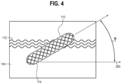
- FIG. 4 depicts a set of base courses 112 forming the base portion 104 and a set of angled raised structure courses 114 forming the raised structure 110 (e.g., four raised structure courses 114 that are interlooped).
- the raised structure courses 114 which each include a plurality of uninterrupted consecutive loops (e.g., formed on a single needle bed in accordance with the tubular knit structure described above), is angled at least 5 degrees relative to the course-wise direction 200 (which is approximately, or exactly, the lengthwise direction of the base courses 112), at least 10 degrees relative to the course-wise direction 200, at least 20 degrees relative to the course-wise direction, or more.
- Specific techniques for forming an angled raised structure 110 are described herein (e.g., with reference to FIG. 5 ).
- Advantages of the angled raised structures 110 include, but are not limited to, desirable aesthetics, particular friction characteristics (e.g., the textile may provide surface friction in particular, select directions based on the angled orientation and size of the raised structures 110), etc.
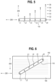
- FIG. 5 is an illustration showing a technique for manufacturing the knitted component 102 with the angled raised structures 110
- FIG. 6 shows the raised structure 110 after completion of the process of FIG. 5
- the raised structure 110 is depicted as a tubular knit structure as it may appear immediately after formation on a knitting machine (e.g., after its courses are coupled to both needle beds to close the "tube").
- the longitudinal axis of the tubular knit structure may be parallel to the course-wise direction 200.
- the raised structure 110 are secured to the base portion (not shown) with a plurality of loops, which are represented in FIGS.
- loops L1 , L2, L3, L4, L5, and L6 although any suitable number of loops may be used to secure the raised structure to the base portion 104.
- the loops L1 -L6 may all be part of the same course, but this is not required, and in some embodiments, a high tenacity yarn may be used to form the loops L1-L6 to provide sufficient strength (as described in more detail below).
- loops L1-L6 may not be directly behind the tubular knit structure, but instead are offset with respect to loops of the tubular knit structure such that they indirectly force the tubular knit structure into an angled orientation even when partially offset from the tubular knit structure through yarn tension (e.g., as is accomplished by the knitted structure of the knit diagram depicted by FIG. 9 ).
- the raised structure 110 is angled relative to the course-wise direction 200 by selectively releasing the loops L1-L6 at different points (e.g., at different courses such that they are offset in the wale-wise direction 202) during the knitting process.
- loop L1 may be released at a first course C1, which may be a course that occurs immediately after finalizing the tubular knit structure forming the raised structure 110.
- the second loop L2 may be held on a needle of the knitting machine until course C2 is formed, which may occur after the course C1 is formed.
- the loop C2 becomes offset in the wale-wise direction 202 in the finished knit product (e.g., offset vertically in FIGS. 5-6 ).
- loops L3-L6 may be selectively released at different respective courses C3-C6 such that the raised structure 110 is angled along its entire length, resulting in the angled raised structure 110 depicted in FIG. 6 .
- the specific angle of the raised structure 110 may be determined by the number of courses formed between when the loops L1-L6 are released. For example, if one course is formed between when each of the loops L1-L6 is released, the angle of the raised structure 110 relative to the course-wise direction 200 will be smaller than if two course are formed between each loop-release step. Further, it is contemplated that different numbers of courses may be knit/formed between the respective loops L1-L6, and thus the angle of the raised structure 110 may vary along its length. Releasing the loops L1-L6 at variable intervals may additionally cause the raised structure to curve in some instances, which is depicted in FIG. 7 .
- FIG. 8 is an illustration showing a first margin 116 extending along a first edge 120 of the raised structure 110 and a second margin 118 extending along a second edge 122 of the raised structure 110, where the edges 120, 122 extend longitudinally along the raised structure 110.
- the margins 116, 118 may be flush (e.g., not substantially elevated) with the base portion 104 of the knitted component 102, and it is contemplated that they may be slightly depressed with respect to the base portion 104 (e.g., such that cavities are formed at the bottom of the raised structure 110).
- Such a depression feature may enhance the definition of the raised structures 110, for example. Further, it is contemplated that at least one of the margins 116, 118 may have a color that is different than a color of the raised structure 110, and/or different than a color of the base portion 104, which may provide desirable aesthetic effects. When two margins 116, 118 are included, the two margins 116, 118 may have the same color, or not.
- the margins 116, 118 may be formed with yarns that are different than the yarns forming the raised structure 110.
- the yarns forming the raised structure 110 may be formed primarily or entirely of polyester (e.g., a strand or multiple strands of textured polyester). This may be advantageous for the desirable softness, durability, and texture characteristics provided by polyester (e.g., when the knitted component 102 is used in an article of apparel or an upper for an article of footwear).
- the yarns incorporated into the margins 116, 118 are what is referred to as a "high-tenacity" yarn, which may be particularly advantageous when it is desired for the margins to exhibit enhanced strength.
- the loop-holding process described above e.g., holding the loops L1-L6 of FIGS. 5-6 on the needle bed for a series of courses
- tenacity is understood to refer to the amount of force (expressed in units of weight, for example: pounds, grams, centinewtons or other units) needed to rupture a yarn (i.e.
- the breaking force or breaking point of the yarn divided by the linear mass density of the yarn expressed, for example, in (unstrained) denier, decitex, or some other measure of weight per unit length.
- the amount of force needed to break a yarn is determined by subjecting a sample of the yarn to a known amount of force by stretching the sample until it breaks, for example, by inserting each end of a sample of the yarn into the grips on the measuring arms of an extensometer, subjecting the sample to a stretching force, and measuring the force required to break the sample using a strain gauge load cell. Suitable testing systems can be obtained from Instron (Norwood, MA, USA). Yarn tenacity and yarn breaking force are distinct from burst strength or bursting strength of a textile, which is a measure of the maximum force that can be applied to the surface of a textile before the surface bursts.
- the minimum tenacity required is approximately 1.5 grams per denier (g/D). 1 g/D corresponds to 8.83 cN/tex.
- Most synthetic polymer continuous filament yarns formed from commodity polymeric materials generally have tenacities in the range of about 1.5 g/D to about 4 g/D.
- polyester filament yarns that may be used in the manufacture of knit uppers for article of footwear have tenacities in the range of about 2.5 g/D to about 4 g/D.
- Filament yarns formed from commodity synthetic polymeric materials which are considered to have high tenacities generally have tenacities in the range of about 5 g/D to about 10 g/D.
- a "high tenacity yarn” generally have tenacities in the range of about 5 g/D to about 10 g/D.
- commercially available package dyed polyethylene terephthalate filament yarn from National Spinning (Washington, NC, USA) has a tenacity of about 6 g/D
- commercially available solution dyed polyethylene terephthalate filament yarn from Far Eastern New Century (Taipei, Taiwan) has a tenacity of about 7 g/D.
- Filament yarns formed from high performance synthetic polymer materials generally have tenacities of about 11 g/D or greater.
- filament yarns formed of aramid typically have tenacities of about 20 g/D
- filament yarns formed of ultra-high molecular weight polyethylene (UFIMWPE) having tenacities greater than 30 g/D are available from Dyneema (Stanley, NC, USA) and Spectra (Honeywell-Spectra, Colonial Heights, VA, USA).
- FIG. 9 is a diagram illustrating an example of a knitting sequence for forming the angled raised structure 110 described above, along with a first margin 116 and a second margin 118.
- courses 1 -6 may correspond with a first margin 116.
- a first yarn 122 of the first margin 116 is a high-tenacity yarn as described above, having a tenacity of at least 5 g/D (such as at least 10 g/D).
- the first yarn 122 may be formed with three loops knitted on a front needle bed (at half-gauge) followed by two loops knitted on a back needle bed (spaced by three needles).
- Two passes of a second yarn 124 which may be a polyester yarn that eventually forms the raised structures (as described above), may be integrated into the first margin 116 on the back needle bed, which may provide a backing on the second side of the knitted component 102.
- each of the raised structures 110 includes six uninterrupted consecutive loops, which are optionally at full gauge on the needle bed (as shown).
- Courses 11-14 of FIG. 9 form the second margin 118.
- the structure of the second margin 118 is similar to the structure of the first margin 116, and the third yarn 126 used to form the second margin 118 may be a high-tenacity yarn. Further, the third yarn 126 may have a different color than at least one of the first yarn and/or the second yarn. In other embodiments, the third yarn 126 may be identical (and even the same strand) as the first yarn 122.
- loops 130 referenced in FIG. 9 which are on the back bed, are held on the back bed while the tubular portion of the raised structure 110 is formed.
- These loops 130 serve as connection points to the back bed of the knitting machine, and holding these loops on the back bed for a number of courses (e.g., as indicated by the lines 132) to force the raised structures 110 to angle (in a manner similar to as described with reference to FIG. 5 , though the loops are offset in the course-wise direction from loops of a corresponding raised structure 110).
- Courses 15-30 are associated with base portion 104 of the knitted component 102. These courses formed a so-called “tubular interlock" structure recognized by those skilled in the art. However, any other suitable base structure may be used in other embodiments.
- the yarns forming the base portion 104 may include any suitable material, such as a high-tenacity material, a polyester, a fusible material, etc. In some embodiments, for example, the base portion 104 may be formed primarily with polyester yarns, which may be desirable in articles of apparel and/or uppers for an article of footwear.
- the knit sequence of FIG. 9 may be repeated, as necessary, to form a knitted component with a suitable size. Further, it is noted that the sequence(s) may be varied to incorporate different features by changing certain knit structures, by varying yarn types, by increasing or decreasing the number of courses at each step, or by any other suitable adjustment to the knitting process or materials used. Further, other sequences may be used before, after, or between the sequences of FIG. 9 .
Landscapes
- Engineering & Computer Science (AREA)
- Textile Engineering (AREA)
- Chemical & Material Sciences (AREA)
- Materials Engineering (AREA)
- Knitting Of Fabric (AREA)
Description
- A variety of articles are formed from textiles. As examples, articles of apparel (e.g., shirts, pants, socks, footwear, jackets and other outerwear, briefs and other undergarments, hats and other headwear), containers (e.g., backpacks, bags), and upholstery for furniture (e.g., chairs, couches, car seats) are often at least partially formed from textiles. These textiles are often formed by weaving or interlooping (e.g., knitting) a yarn or a plurality of yarns, usually through a mechanical process involving looms or knitting machines.
- In some articles, it may be desirable to include a raised structure via a tubular knit structure. Typically, tubular knit structures extend along a course-wise direction of a knitted component. The present disclosure describes knitting techniques and structures for including an angled raised structure.
-
EP 3 138 431 A1claim 1, and a method for knitting the shoe upper. The shoe upper includes a linear anti-stretch section, knitted integrally to an instep cover section. The anti-stretch section includes a pipe-form knitted fabric portion configured with a knitting yarn including a heat fusible yarn, and an inserting knitting yarn inserted inside the pipe-form knitted fabric portion and fixed by tuck stitches configuring the pipe-form knitted fabric portion. -
US 2018 042 333 A1 discloses an article which may include a knitted component with a first zone, the first zone being at least partially formed with a first yarn and a second yarn. The first yarn may be a monofilament yarn. The second yarn may have a tenacity of at least 5 grams per denier (g/D). The first yarn and the second yarn may be adjacent at least at one location within the first zone. - The objective technical problem to be solved may be considered to consist in overcoming or at least reducing the disadvantages according to the prior art. The problem is solved by the subject matter of the independent claim. The embodiments will be further described in connection with
Figure 8 and9 of the attached drawings. It is intended that the drawings included as a part of this specification be illustrative of the exemplary embodiments and should in no way be considered as a limitation on the scope of the present disclosure. Indeed, the present disclosure specifically contemplates other embodiments not illustrated but intended to be included in the claims. -
FIG. 1 is an illustration showing a front view of a knitted component with an angled raised structure in accordance with certain aspects of the present disclosure. -
FIG. 2 is an illustration showing a magnified view of a portion of the knitted component ofFIG. 1 . -
FIG. 3 is an illustration showing a side view of a tubular knit structure forming a raised structure in accordance with certain aspects of the present disclosure. -
FIG. 4 is an illustration showing an angled raised structure, including angled raised structure courses, that is angled with respect to a course-wise direction of the knitted component in accordance with certain aspects of the present disclosure. -
FIG. 5 is an illustration showing a knitting technique, including selectively holding loops coupled to the raised structure for a select period of time, for manufacturing an angled raised structure in accordance with certain aspects of the present disclosure. -
FIG. 6 is an illustration showing an angled raised structure manufacturing in accordance with the technique illustrated inFIG. 5 . -
FIG. 7 is an illustration showing a curved raised structure in accordance with certain aspects of the present disclosure. -
FIG. 8 is an illustration showing an angled raised structure along with a first margin and a second margin extending along longitudinal edges of the raised structure in accordance with the present invention. -
FIG. 9 is a diagram showing a potential knitting sequence for forming a knitted component having an angled raised structure in accordance with the present invention. - Various aspects are described below with reference to the drawings in which like elements generally are identified by like numerals. The relationship and functioning of the various elements of the aspects may better be understood by reference to the following detailed description. However, aspects are not limited to those illustrated in the drawings or explicitly described below. It also should be understood that the drawings are not necessarily to scale, and in certain instances details may have been omitted that are not necessary for an understanding of aspects disclosed herein, such as conventional fabrication and assembly.
- Certain aspects of the present disclosure relate to articles at least partially formed from textiles. One example of an article is an article of apparel (e.g., shirts, pants, socks, footwear, jackets and other outerwear, briefs and other undergarments, hats and other headwear, or the like). The article may be an upper configured for use in an article of footwear. The upper may be used in connection with any type of footwear. Illustrative, non-limiting examples of articles of footwear include a basketball shoe, a biking shoe, a cross-training shoe, a global football (soccer) shoe, an American football shoe, a bowling shoe, a golf shoe, a hiking shoe, a ski or snowboarding boot, a tennis shoe, a running shoe, and a walking shoe. The upper may also be incorporated into a non-athletic shoe, such as a dress shoe, a loafer, and a sandal.
- The present disclosure relates to a knitted component according to the subject matter of
claim 1. - Optionally, the raised structure further includes a second course and a third course, where the first course is interlooped with the second course, and where the second course is interlooped with the third course. A first loop may couple a first end of the raised structure to the base portion of the knitted component, where a second loop couples a second end of the raised structure to the base portion, and where the first loop and the second loop are offset in a wale-wise direction, the wale-wise direction being perpendicular to the course-wise direction. At least one of the first loop and the second loop may be formed with at least one yarn having a tenacity greater than about 5 g/D.
- A margin extending along a longitudinal edge of the raised structure is included, where the margin is formed with a yarn having a tenacity greater than about 5 g/D. The margin may have a color that is different than a color of the raised structure.
- The raised structure may be elevated at least 3 mm with respect to the base portion of the knitted component. The raised structure may have a length of at least 5 mm.
- The base portion includes a plurality of courses extending generally in the course-wise direction such that the plurality of courses of the base portion are angled relative to the raised structure.
- Background information useful for understanding the invention relates to a method for forming a knitted component. The method may include knitting a tubular knit structure to form a raised structure on a base portion of a knitted component, securing the tubular knit structure a first loop and a second loop, interlooping the first loop to a base portion of the knitted component at a first location, holding the second loop on a needle bed of a knitting machine while knitting at least two courses of the base portion with the knitting machine, and interlooping the second loop to the base portion of the knitted component at a second location. The first location and the second location may be offset in a wale-wise direction such that the raised structure is angled.
-
FIG. 1 is an illustration showing a front view (e.g., a first side) of a knittedcomponent 102 that may be used in any of the examples above (e.g., an upper for an article of footwear or an article of apparel).FIG. 2 is a magnified view of a portion of the knittedcomponent 102 ofFIG. 1 . Referring toFIGS. 1 -2 , abase portion 104 of the knittedcomponent 102 is formed with a plurality of courses extending generally in acourse-wise direction 200 of the knitted component. Thecourse-wise direction 200 is defined by the direction that a feeder moves on a knitting machine when forming courses of the knitted component on a needle bed (e.g., as described inU.S. Patent No. 8, 522, 577, filed on March 15, 2011 asU.S. Patent Application No. 13/048,527 ). Thecourse-wise direction 200 of the knittedcomponent 102 is apparent to those skilled in the art upon viewing the structure of the knittedcomponent 102, since thecourse-wise direction 200 is the direction that the majority of the courses of the knittedcomponent 102 generally follow (at any given location). In some examples thecourse-wise direction 200 may change along the knitted component 102 (e.g., when the knittedcomponent 102 has a curved feature) when the knittedcomponent 102 is in a resting state, but thecourse-wise direction 200 is constant during manufacturing (e.g., corresponding to the needle bed of the knitting machine). Similarly, awale-wise direction 202, which is defined as the direction perpendicular to thecourse-wise direction 200, generally follows the direction of the majority of the wales of the knittedcomponent 102. - The knitted
component 102 includes one or more raisedstructures 110 that extend from thefirst side 106 of thebase portion 104. A second side of thebase portion 104, which is located on the opposite side of the textile (and thus not visible inFIGS. 1-2 ), may additionally or alternatively include raised structures. The raised structures are formed generally of tubular knit structures known to form "ottomans" or "welts" on a fabric by knitting a series of consecutive courses (each having a plurality of uninterrupted consecutive loops) on a single needle bed of a knitting machine and then locking those courses to a second needle bed, thus forming a multi-layer knit structure where one layer has more courses than the other layer to provide the self-elevating tubular knit structure (as described in more detail below). In certain embodiments, theraised structures 110 may be raised at least about 2 mm relative to thebase portion 104, such as about 4 mm in certain exemplary embodiments. The raisedstructures 110 may each include approximately the same elevation, or at least some of the raisedstructures 110 may have different elevations than others. While any suitable length is contemplated, the raisedstructures 110 of the depicted embodiment may have length of at least about 5mm, such as about 10 mm. Desirable lengths of the raisedstructures 110 may be determined by the types of manufacturing techniques used (e.g., the knitting sequence(s) as described in more detail below), and/or by the desired physical and/or aesthetic characteristics of the knittedcomponent 102. - Referring to
FIG. 3 , which is an illustration showing a side view of an example of a raisedstructure 110, the raisedstructure 110 may be generally formed with a knitting technique that forms a tubular knit structure, such as a technique where a number of courses are formed on a single needle bed of the knitting machine alone without knitting on the second needle bed (see, e.g., the raisedstructure 110 indicated in the knit diagram ofFIG. 9 ). The raisedstructure 110 may therefore comprise more courses and/or more loops on afirst side 106 of the knittedcomponent 102 relative to the number of courses and/or loops on thesecond side 108, the therefore the raisedstructure 110 has a tendency to elevate from thefirst side 106 relative to the surroundingbase portion 104. Thefirst side 106 and thesecond side 108 may include separable layers at the raisedstructure 110 due to the tubular structure, and thus the raisedstructure 110 may have an opening orpocket 111 therein located between thefirst side 106 and thesecond side 108, which optionally may be filled with another component (e.g., a non-knit component supplied after knitting). - Typically, a tubular knit structure is an elongated feature that extends lengthwise in the
course-wise direction 200. However, as described herein, the presently-described raisedstructures 110 is angled with respect to thecourse-wise direction 200. That is, the longitudinal axis 206 of the raisedstructure 110, is angled with respect to the course-wise direction 200 (at a depicted angle Q, for example). To illustrate,FIG. 4 depicts a set ofbase courses 112 forming thebase portion 104 and a set of angled raisedstructure courses 114 forming the raised structure 110 (e.g., four raisedstructure courses 114 that are interlooped). As shown, the raisedstructure courses 114, which each include a plurality of uninterrupted consecutive loops (e.g., formed on a single needle bed in accordance with the tubular knit structure described above), is angled at least 5 degrees relative to the course-wise direction 200 (which is approximately, or exactly, the lengthwise direction of the base courses 112), at least 10 degrees relative to thecourse-wise direction 200, at least 20 degrees relative to the course-wise direction, or more. Specific techniques for forming an angled raisedstructure 110 are described herein (e.g., with reference toFIG. 5 ). Advantages of the angled raisedstructures 110 include, but are not limited to, desirable aesthetics, particular friction characteristics (e.g., the textile may provide surface friction in particular, select directions based on the angled orientation and size of the raised structures 110), etc. -
FIG. 5 is an illustration showing a technique for manufacturing the knittedcomponent 102 with the angled raisedstructures 110, andFIG. 6 shows the raisedstructure 110 after completion of the process ofFIG. 5 . Referring toFIG. 5 , the raisedstructure 110 is depicted as a tubular knit structure as it may appear immediately after formation on a knitting machine (e.g., after its courses are coupled to both needle beds to close the "tube"). As shown, in this instant, the longitudinal axis of the tubular knit structure may be parallel to thecourse-wise direction 200. The raisedstructure 110 are secured to the base portion (not shown) with a plurality of loops, which are represented inFIGS. 5-6 as loops L1 , L2, L3, L4, L5, and L6 (although any suitable number of loops may be used to secure the raised structure to thebase portion 104. The loops L1 -L6 may all be part of the same course, but this is not required, and in some embodiments, a high tenacity yarn may be used to form the loops L1-L6 to provide sufficient strength (as described in more detail below). Further, the loops L1-L6 may not be directly behind the tubular knit structure, but instead are offset with respect to loops of the tubular knit structure such that they indirectly force the tubular knit structure into an angled orientation even when partially offset from the tubular knit structure through yarn tension (e.g., as is accomplished by the knitted structure of the knit diagram depicted byFIG. 9 ). - Still referring to
FIG. 5 , the raisedstructure 110 is angled relative to thecourse-wise direction 200 by selectively releasing the loops L1-L6 at different points (e.g., at different courses such that they are offset in the wale-wise direction 202) during the knitting process. For example, loop L1 may be released at a first course C1, which may be a course that occurs immediately after finalizing the tubular knit structure forming the raisedstructure 110. The second loop L2 may be held on a needle of the knitting machine until course C2 is formed, which may occur after the course C1 is formed. As a result, the loop C2 becomes offset in thewale-wise direction 202 in the finished knit product (e.g., offset vertically inFIGS. 5-6 ). Similarly, loops L3-L6 may be selectively released at different respective courses C3-C6 such that the raisedstructure 110 is angled along its entire length, resulting in the angled raisedstructure 110 depicted inFIG. 6 . - The specific angle of the raised
structure 110 may be determined by the number of courses formed between when the loops L1-L6 are released. For example, if one course is formed between when each of the loops L1-L6 is released, the angle of the raisedstructure 110 relative to thecourse-wise direction 200 will be smaller than if two course are formed between each loop-release step. Further, it is contemplated that different numbers of courses may be knit/formed between the respective loops L1-L6, and thus the angle of the raisedstructure 110 may vary along its length. Releasing the loops L1-L6 at variable intervals may additionally cause the raised structure to curve in some instances, which is depicted inFIG. 7 . - High-strength and/or visually-appealing margins are included on at least one side of the raised
structure 110, and such margins form the loops L1 -L6.FIG. 8 is an illustration showing afirst margin 116 extending along afirst edge 120 of the raisedstructure 110 and asecond margin 118 extending along asecond edge 122 of the raisedstructure 110, where theedges structure 110. Themargins base portion 104 of the knittedcomponent 102, and it is contemplated that they may be slightly depressed with respect to the base portion 104 (e.g., such that cavities are formed at the bottom of the raised structure 110). Such a depression feature may enhance the definition of the raisedstructures 110, for example. Further, it is contemplated that at least one of themargins structure 110, and/or different than a color of thebase portion 104, which may provide desirable aesthetic effects. When twomargins margins - The
margins structure 110. For example, in some embodiments, the yarns forming the raisedstructure 110 may be formed primarily or entirely of polyester (e.g., a strand or multiple strands of textured polyester). This may be advantageous for the desirable softness, durability, and texture characteristics provided by polyester (e.g., when theknitted component 102 is used in an article of apparel or an upper for an article of footwear). - The yarns incorporated into the
margins FIGS. 5-6 on the needle bed for a series of courses) may require enhanced strength relative to typically-used yarns to prevent yarn breakages during knitting. As used herein, "tenacity" is understood to refer to the amount of force (expressed in units of weight, for example: pounds, grams, centinewtons or other units) needed to rupture a yarn (i.e. , the breaking force or breaking point of the yarn), divided by the linear mass density of the yarn expressed, for example, in (unstrained) denier, decitex, or some other measure of weight per unit length. The amount of force needed to break a yarn (the "breaking force" of the yarn) is determined by subjecting a sample of the yarn to a known amount of force by stretching the sample until it breaks, for example, by inserting each end of a sample of the yarn into the grips on the measuring arms of an extensometer, subjecting the sample to a stretching force, and measuring the force required to break the sample using a strain gauge load cell. Suitable testing systems can be obtained from Instron (Norwood, MA, USA). Yarn tenacity and yarn breaking force are distinct from burst strength or bursting strength of a textile, which is a measure of the maximum force that can be applied to the surface of a textile before the surface bursts. - Generally, in order for a yarn to withstand the forces applied in an industrial knitting machine, the minimum tenacity required is approximately 1.5 grams per denier (g/D). 1 g/D corresponds to 8.83 cN/tex. Most synthetic polymer continuous filament yarns formed from commodity polymeric materials generally have tenacities in the range of about 1.5 g/D to about 4 g/D. For example, polyester filament yarns that may be used in the manufacture of knit uppers for article of footwear have tenacities in the range of about 2.5 g/D to about 4 g/D. Filament yarns formed from commodity synthetic polymeric materials which are considered to have high tenacities (e.g., a "high tenacity yarn") generally have tenacities in the range of about 5 g/D to about 10 g/D. For example, commercially available package dyed polyethylene terephthalate filament yarn from National Spinning (Washington, NC, USA) has a tenacity of about 6 g/D, and commercially available solution dyed polyethylene terephthalate filament yarn from Far Eastern New Century (Taipei, Taiwan) has a tenacity of about 7 g/D. Filament yarns formed from high performance synthetic polymer materials generally have tenacities of about 11 g/D or greater. For example, filament yarns formed of aramid typically have tenacities of about 20 g/D, and filament yarns formed of ultra-high molecular weight polyethylene (UFIMWPE) having tenacities greater than 30 g/D are available from Dyneema (Stanley, NC, USA) and Spectra (Honeywell-Spectra, Colonial Heights, VA, USA).
-
FIG. 9 is a diagram illustrating an example of a knitting sequence for forming the angled raisedstructure 110 described above, along with afirst margin 116 and asecond margin 118. As shown, courses 1 -6 may correspond with afirst margin 116. Afirst yarn 122 of thefirst margin 116 is a high-tenacity yarn as described above, having a tenacity of at least 5 g/D (such as at least 10 g/D). In thefirst margin 116, thefirst yarn 122 may be formed with three loops knitted on a front needle bed (at half-gauge) followed by two loops knitted on a back needle bed (spaced by three needles). Two passes of asecond yarn 124, which may be a polyester yarn that eventually forms the raised structures (as described above), may be integrated into thefirst margin 116 on the back needle bed, which may provide a backing on the second side of the knittedcomponent 102. - Referring to courses 7-10 of
FIG. 9 , four courses of tubular knitting (e.g., front bed only) with the second (polyester)yarn 124 may be performed to form the first side 106 (FIG. 3 ) of the raisedstructures 110. More or less than four courses of tubular knitting are contemplated, but four course may be used with a particular machine setup to obtain raisedstructures 110 that are elevated about 3 mm from thebase portion 104. Further, each of the raisedstructures 110 includes six uninterrupted consecutive loops, which are optionally at full gauge on the needle bed (as shown). - Courses 11-14 of
FIG. 9 form thesecond margin 118. As shown the structure of thesecond margin 118 is similar to the structure of thefirst margin 116, and thethird yarn 126 used to form thesecond margin 118 may be a high-tenacity yarn. Further, thethird yarn 126 may have a different color than at least one of the first yarn and/or the second yarn. In other embodiments, thethird yarn 126 may be identical (and even the same strand) as thefirst yarn 122. - Notably, the loops 130 referenced in
FIG. 9 , which are on the back bed, are held on the back bed while the tubular portion of the raisedstructure 110 is formed. These loops 130 serve as connection points to the back bed of the knitting machine, and holding these loops on the back bed for a number of courses (e.g., as indicated by the lines 132) to force the raisedstructures 110 to angle (in a manner similar to as described with reference toFIG. 5 , though the loops are offset in the course-wise direction from loops of a corresponding raised structure 110). - Courses 15-30 are associated with
base portion 104 of the knittedcomponent 102. These courses formed a so-called "tubular interlock" structure recognized by those skilled in the art. However, any other suitable base structure may be used in other embodiments. The yarns forming thebase portion 104 may include any suitable material, such as a high-tenacity material, a polyester, a fusible material, etc. In some embodiments, for example, thebase portion 104 may be formed primarily with polyester yarns, which may be desirable in articles of apparel and/or uppers for an article of footwear. - The knit sequence of
FIG. 9 may be repeated, as necessary, to form a knitted component with a suitable size. Further, it is noted that the sequence(s) may be varied to incorporate different features by changing certain knit structures, by varying yarn types, by increasing or decreasing the number of courses at each step, or by any other suitable adjustment to the knitting process or materials used. Further, other sequences may be used before, after, or between the sequences ofFIG. 9 .
Claims (8)
- A knitted component (102), comprising:a base portion (104) formed with a plurality of courses (112) extending generally in a course-wise direction (200) of the knitted component (102); anda tubular knit structure forming a raised structure (110) located on a first side (106) of the base portion (104); wherein the raised structure (110) includes a plurality of uninterrupted consecutive loops of a first course (114),wherein the first course (114) of the raised structure (110) is angled at least 5 degrees relative to the course-wise direction (200) of the base courses (112) at a location immediately adjacent to the tubular knit structure, andwherein the knitted component (102) further comprises a margin (116, 118) extending along a longitudinal edge (120, 122) of the raised structure (110),characterised in that the margin (116, 118) is formed with a yarn (122, 126) having a tenacity greater than about 44.15 cN/tex (5g/D).
- The knitted component (102) of claim 1,
wherein the raised structure (110) further includes a second course (114) and a third course (114), wherein the first course (114) is interlooped with the second course (114), and wherein the second course (114) is interlooped with the third course (114). - The knitted component (102) of claim 1, wherein a first loop (L1) couples a first end of the raised structure (110) to the base portion (104) of the knitted component (102), wherein a second loop (L6) couples a second end of the raised structure (110) to the base portion (104), and wherein the first loop (L1) and the second loop (L6) are offset in a wale-wise direction (202), the wale-wise direction (202) being perpendicular to the course-wise direction (200).
- The knitted component (102) of claim 3, wherein at least one of the first loop (L1) and the second loop (L6) is formed with at least one yarn (122, 126) having a tenacity greater than about 44.15 cN/tex (5g/D),
- The knitted component (102) of claim 1, wherein the margin (116, 118) has a color that is different than a color of the raised structure (110).
- The knitted component (102) of claim 1, wherein the raised structure (110) is elevated at least 3 mm with respect to the base portion (104) of the knitted component (102).
- The knitted component of claim 1, wherein the raised structure (110) has a length of at least 5 mm.
- The knitted component (102) of claim 1, wherein the base portion (104) includes a plurality of courses (112) extending generally in the course-wise direction (200) such that the plurality of courses (112) of the base portion (104) are angled relative to the raised structure (110).
Priority Applications (1)
| Application Number | Priority Date | Filing Date | Title |
|---|---|---|---|
| EP23175658.6A EP4234785B1 (en) | 2018-07-23 | 2019-07-23 | Knitted component with an angled raised structure |
Applications Claiming Priority (2)
| Application Number | Priority Date | Filing Date | Title |
|---|---|---|---|
| US201862702192P | 2018-07-23 | 2018-07-23 | |
| PCT/US2019/042960 WO2020023468A1 (en) | 2018-07-23 | 2019-07-23 | Knitted component with an angled raised structure |
Related Child Applications (1)
| Application Number | Title | Priority Date | Filing Date |
|---|---|---|---|
| EP23175658.6A Division EP4234785B1 (en) | 2018-07-23 | 2019-07-23 | Knitted component with an angled raised structure |
Publications (2)
| Publication Number | Publication Date |
|---|---|
| EP3827120A1 EP3827120A1 (en) | 2021-06-02 |
| EP3827120B1 true EP3827120B1 (en) | 2023-05-31 |
Family
ID=67544401
Family Applications (2)
| Application Number | Title | Priority Date | Filing Date |
|---|---|---|---|
| EP23175658.6A Active EP4234785B1 (en) | 2018-07-23 | 2019-07-23 | Knitted component with an angled raised structure |
| EP19749950.2A Active EP3827120B1 (en) | 2018-07-23 | 2019-07-23 | Knitted component with an angled raised structure |
Family Applications Before (1)
| Application Number | Title | Priority Date | Filing Date |
|---|---|---|---|
| EP23175658.6A Active EP4234785B1 (en) | 2018-07-23 | 2019-07-23 | Knitted component with an angled raised structure |
Country Status (4)
| Country | Link |
|---|---|
| US (3) | US11466387B2 (en) |
| EP (2) | EP4234785B1 (en) |
| CN (2) | CN112469854B (en) |
| WO (1) | WO2020023468A1 (en) |
Families Citing this family (10)
| Publication number | Priority date | Publication date | Assignee | Title |
|---|---|---|---|---|
| WO2019001676A1 (en) | 2017-06-27 | 2019-01-03 | Puma SE | Shoe, especially sports shoe |
| EP4520858A3 (en) | 2018-07-23 | 2025-05-28 | NIKE Innovate C.V. | Knitted article with raised structure and methods of manufacture |
| WO2020023468A1 (en) * | 2018-07-23 | 2020-01-30 | Nike Innovate C.V. | Knitted component with an angled raised structure |
| CN115998034A (en) * | 2018-10-19 | 2023-04-25 | 耐克创新有限合伙公司 | Knitted component with raised structure and method of manufacture |
| USD935760S1 (en) | 2019-07-23 | 2021-11-16 | Puma SE | Shoe |
| USD932762S1 (en) | 2019-07-23 | 2021-10-12 | Puma SE | Shoe |
| EP4087433B1 (en) * | 2020-01-08 | 2024-08-21 | Nike Innovate C.V. | Upper for an article of footwear having three yarn types |
| CN113668129B (en) * | 2021-07-19 | 2022-12-09 | 信泰(福建)科技有限公司 | Knitted fabric containing three-dimensional decorative texture and vamp |
| CN113668126B (en) * | 2021-07-26 | 2022-12-13 | 信泰(福建)科技有限公司 | Knitted fabric with shaking table bending and bulging effects, knitting method and shoe upper |
| IT202300012498A1 (en) * | 2023-06-16 | 2024-12-16 | Tex Tech S R L | 3D SOUND-ABSORBING/SOUND-CORRECTOR FABRIC |
Family Cites Families (15)
| Publication number | Priority date | Publication date | Assignee | Title |
|---|---|---|---|---|
| JPS60181351A (en) | 1984-02-28 | 1985-09-17 | 名草繊維株式会社 | Knitted cloth and knitting machine |
| DE102008027856A1 (en) | 2008-06-11 | 2009-12-24 | W. L. Gore & Associates Gmbh | Shoe with ventilation in the lower shaft area and air-permeable spacer construction |
| US8490299B2 (en) * | 2008-12-18 | 2013-07-23 | Nike, Inc. | Article of footwear having an upper incorporating a knitted component |
| US8522577B2 (en) | 2011-03-15 | 2013-09-03 | Nike, Inc. | Combination feeder for a knitting machine |
| US9510636B2 (en) * | 2012-02-20 | 2016-12-06 | Nike, Inc. | Article of footwear incorporating a knitted component with an integral knit tongue |
| HK1216908A1 (en) * | 2013-03-07 | 2016-12-09 | Grt Developments Pty Limited | Fabric system |
| JP6153659B2 (en) * | 2014-05-02 | 2017-06-28 | 株式会社島精機製作所 | Shoe upper and knitting method of shoe upper |
| US9661892B2 (en) * | 2014-07-29 | 2017-05-30 | Nike, Inc. | Article of footwear incorporating an upper with a shifted knit structure |
| US9078488B1 (en) * | 2014-09-30 | 2015-07-14 | Nike, Inc. | Article of footwear incorporating a lenticular knit structure |
| CN107208333B (en) * | 2015-01-30 | 2020-08-18 | 耐克创新有限合伙公司 | Method of forming a knitted component and method of assembling an article of footwear containing a knitted component |
| CN109714998B (en) | 2016-08-12 | 2021-11-02 | 耐克创新有限合伙公司 | Article having a first section with a first yarn and a second yarn |
| CN117286624B (en) * | 2016-08-26 | 2026-01-27 | 耐克创新有限合伙公司 | Knitted component including cushioning structure, upper and method of manufacturing an article of footwear |
| CN107268165A (en) * | 2017-05-22 | 2017-10-20 | 浙江华诗秀新材料科技有限公司 | Leg protector and its half of arc gradual change Stress control knitting method of tubulose |
| CN114668213B (en) * | 2018-04-16 | 2025-10-31 | 耐克创新有限合伙公司 | Shoe upper including knitted cushioning region and article of footwear incorporating same |
| WO2020023468A1 (en) * | 2018-07-23 | 2020-01-30 | Nike Innovate C.V. | Knitted component with an angled raised structure |
-
2019
- 2019-07-23 WO PCT/US2019/042960 patent/WO2020023468A1/en not_active Ceased
- 2019-07-23 EP EP23175658.6A patent/EP4234785B1/en active Active
- 2019-07-23 EP EP19749950.2A patent/EP3827120B1/en active Active
- 2019-07-23 US US16/519,313 patent/US11466387B2/en active Active
- 2019-07-23 CN CN201980048915.0A patent/CN112469854B/en active Active
- 2019-07-23 CN CN202211135980.7A patent/CN115568660B/en active Active
-
2022
- 2022-09-23 US US17/951,574 patent/US12195890B2/en active Active
-
2025
- 2025-01-13 US US19/019,019 patent/US20250146194A1/en active Pending
Also Published As
| Publication number | Publication date |
|---|---|
| EP4234785A2 (en) | 2023-08-30 |
| CN115568660B (en) | 2026-01-02 |
| CN112469854A (en) | 2021-03-09 |
| CN112469854B (en) | 2022-10-04 |
| WO2020023468A1 (en) | 2020-01-30 |
| US20200022447A1 (en) | 2020-01-23 |
| US12195890B2 (en) | 2025-01-14 |
| US20230013080A1 (en) | 2023-01-19 |
| EP4234785A3 (en) | 2023-09-27 |
| CN115568660A (en) | 2023-01-06 |
| EP3827120A1 (en) | 2021-06-02 |
| US20250146194A1 (en) | 2025-05-08 |
| EP4234785B1 (en) | 2026-04-22 |
| US11466387B2 (en) | 2022-10-11 |
| WO2020023468A4 (en) | 2020-05-07 |
Similar Documents
| Publication | Publication Date | Title |
|---|---|---|
| EP4234785B1 (en) | Knitted component with an angled raised structure | |
| US12297569B2 (en) | Knitted component and method of manufacturing the same | |
| US11725312B2 (en) | Knitted component with vertical inlay and method of making the same | |
| EP3496561B1 (en) | Article having a first zone with first and second yarns | |
| US8522577B2 (en) | Combination feeder for a knitting machine | |
| EP3537911B1 (en) | Upper including a knitted component and a tab element | |
| US20120233882A1 (en) | Article Of Footwear Incorporating A Knitted Component | |
| EP4079953B1 (en) | Textile component with embroidered emblem | |
| HK40046052B (en) | Knitted component with an angled raised structure | |
| HK40086034A (en) | Knitted component with an angled raised structure | |
| HK40046052A (en) | Knitted component with an angled raised structure | |
| US12557871B2 (en) | Reinforced knit channel for an article of footwear | |
| HK40056610A (en) | Knitted component with vertical inlay, a method of making same and a knitting machine suitable therefore | |
| WO2024178343A1 (en) | Reinforced knit channel for an article of footwear | |
| WO2025128970A1 (en) | Interlaced knitted component and methods of manufacture |
Legal Events
| Date | Code | Title | Description |
|---|---|---|---|
| STAA | Information on the status of an ep patent application or granted ep patent |
Free format text: STATUS: UNKNOWN |
|
| STAA | Information on the status of an ep patent application or granted ep patent |
Free format text: STATUS: THE INTERNATIONAL PUBLICATION HAS BEEN MADE |
|
| PUAI | Public reference made under article 153(3) epc to a published international application that has entered the european phase |
Free format text: ORIGINAL CODE: 0009012 |
|
| STAA | Information on the status of an ep patent application or granted ep patent |
Free format text: STATUS: REQUEST FOR EXAMINATION WAS MADE |
|
| 17P | Request for examination filed |
Effective date: 20210218 |
|
| AK | Designated contracting states |
Kind code of ref document: A1 Designated state(s): AL AT BE BG CH CY CZ DE DK EE ES FI FR GB GR HR HU IE IS IT LI LT LU LV MC MK MT NL NO PL PT RO RS SE SI SK SM TR |
|
| DAV | Request for validation of the european patent (deleted) | ||
| DAX | Request for extension of the european patent (deleted) | ||
| GRAP | Despatch of communication of intention to grant a patent |
Free format text: ORIGINAL CODE: EPIDOSNIGR1 |
|
| STAA | Information on the status of an ep patent application or granted ep patent |
Free format text: STATUS: GRANT OF PATENT IS INTENDED |
|
| INTG | Intention to grant announced |
Effective date: 20230103 |
|
| GRAS | Grant fee paid |
Free format text: ORIGINAL CODE: EPIDOSNIGR3 |
|
| GRAA | (expected) grant |
Free format text: ORIGINAL CODE: 0009210 |
|
| STAA | Information on the status of an ep patent application or granted ep patent |
Free format text: STATUS: THE PATENT HAS BEEN GRANTED |
|
| AK | Designated contracting states |
Kind code of ref document: B1 Designated state(s): AL AT BE BG CH CY CZ DE DK EE ES FI FR GB GR HR HU IE IS IT LI LT LU LV MC MK MT NL NO PL PT RO RS SE SI SK SM TR |
|
| REG | Reference to a national code |
Ref country code: GB Ref legal event code: FG4D Ref country code: CH Ref legal event code: EP |
|
| REG | Reference to a national code |
Ref country code: AT Ref legal event code: REF Ref document number: 1570966 Country of ref document: AT Kind code of ref document: T Effective date: 20230615 Ref country code: DE Ref legal event code: R096 Ref document number: 602019029572 Country of ref document: DE |
|
| P01 | Opt-out of the competence of the unified patent court (upc) registered |
Effective date: 20230515 |
|
| REG | Reference to a national code |
Ref country code: IE Ref legal event code: FG4D |
|
| REG | Reference to a national code |
Ref country code: LT Ref legal event code: MG9D |
|
| REG | Reference to a national code |
Ref country code: NL Ref legal event code: MP Effective date: 20230531 |
|
| REG | Reference to a national code |
Ref country code: AT Ref legal event code: MK05 Ref document number: 1570966 Country of ref document: AT Kind code of ref document: T Effective date: 20230531 |
|
| PG25 | Lapsed in a contracting state [announced via postgrant information from national office to epo] |
Ref country code: SE Free format text: LAPSE BECAUSE OF FAILURE TO SUBMIT A TRANSLATION OF THE DESCRIPTION OR TO PAY THE FEE WITHIN THE PRESCRIBED TIME-LIMIT Effective date: 20230531 Ref country code: NO Free format text: LAPSE BECAUSE OF FAILURE TO SUBMIT A TRANSLATION OF THE DESCRIPTION OR TO PAY THE FEE WITHIN THE PRESCRIBED TIME-LIMIT Effective date: 20230831 Ref country code: ES Free format text: LAPSE BECAUSE OF FAILURE TO SUBMIT A TRANSLATION OF THE DESCRIPTION OR TO PAY THE FEE WITHIN THE PRESCRIBED TIME-LIMIT Effective date: 20230531 Ref country code: AT Free format text: LAPSE BECAUSE OF FAILURE TO SUBMIT A TRANSLATION OF THE DESCRIPTION OR TO PAY THE FEE WITHIN THE PRESCRIBED TIME-LIMIT Effective date: 20230531 |
|
| PG25 | Lapsed in a contracting state [announced via postgrant information from national office to epo] |
Ref country code: RS Free format text: LAPSE BECAUSE OF FAILURE TO SUBMIT A TRANSLATION OF THE DESCRIPTION OR TO PAY THE FEE WITHIN THE PRESCRIBED TIME-LIMIT Effective date: 20230531 Ref country code: PL Free format text: LAPSE BECAUSE OF FAILURE TO SUBMIT A TRANSLATION OF THE DESCRIPTION OR TO PAY THE FEE WITHIN THE PRESCRIBED TIME-LIMIT Effective date: 20230531 Ref country code: NL Free format text: LAPSE BECAUSE OF FAILURE TO SUBMIT A TRANSLATION OF THE DESCRIPTION OR TO PAY THE FEE WITHIN THE PRESCRIBED TIME-LIMIT Effective date: 20230531 Ref country code: LV Free format text: LAPSE BECAUSE OF FAILURE TO SUBMIT A TRANSLATION OF THE DESCRIPTION OR TO PAY THE FEE WITHIN THE PRESCRIBED TIME-LIMIT Effective date: 20230531 Ref country code: LT Free format text: LAPSE BECAUSE OF FAILURE TO SUBMIT A TRANSLATION OF THE DESCRIPTION OR TO PAY THE FEE WITHIN THE PRESCRIBED TIME-LIMIT Effective date: 20230531 Ref country code: IS Free format text: LAPSE BECAUSE OF FAILURE TO SUBMIT A TRANSLATION OF THE DESCRIPTION OR TO PAY THE FEE WITHIN THE PRESCRIBED TIME-LIMIT Effective date: 20230930 Ref country code: HR Free format text: LAPSE BECAUSE OF FAILURE TO SUBMIT A TRANSLATION OF THE DESCRIPTION OR TO PAY THE FEE WITHIN THE PRESCRIBED TIME-LIMIT Effective date: 20230531 Ref country code: GR Free format text: LAPSE BECAUSE OF FAILURE TO SUBMIT A TRANSLATION OF THE DESCRIPTION OR TO PAY THE FEE WITHIN THE PRESCRIBED TIME-LIMIT Effective date: 20230901 |
|
| PG25 | Lapsed in a contracting state [announced via postgrant information from national office to epo] |
Ref country code: FI Free format text: LAPSE BECAUSE OF FAILURE TO SUBMIT A TRANSLATION OF THE DESCRIPTION OR TO PAY THE FEE WITHIN THE PRESCRIBED TIME-LIMIT Effective date: 20230531 |
|
| PG25 | Lapsed in a contracting state [announced via postgrant information from national office to epo] |
Ref country code: SK Free format text: LAPSE BECAUSE OF FAILURE TO SUBMIT A TRANSLATION OF THE DESCRIPTION OR TO PAY THE FEE WITHIN THE PRESCRIBED TIME-LIMIT Effective date: 20230531 |
|
| PG25 | Lapsed in a contracting state [announced via postgrant information from national office to epo] |
Ref country code: SM Free format text: LAPSE BECAUSE OF FAILURE TO SUBMIT A TRANSLATION OF THE DESCRIPTION OR TO PAY THE FEE WITHIN THE PRESCRIBED TIME-LIMIT Effective date: 20230531 Ref country code: SK Free format text: LAPSE BECAUSE OF FAILURE TO SUBMIT A TRANSLATION OF THE DESCRIPTION OR TO PAY THE FEE WITHIN THE PRESCRIBED TIME-LIMIT Effective date: 20230531 Ref country code: RO Free format text: LAPSE BECAUSE OF FAILURE TO SUBMIT A TRANSLATION OF THE DESCRIPTION OR TO PAY THE FEE WITHIN THE PRESCRIBED TIME-LIMIT Effective date: 20230531 Ref country code: PT Free format text: LAPSE BECAUSE OF FAILURE TO SUBMIT A TRANSLATION OF THE DESCRIPTION OR TO PAY THE FEE WITHIN THE PRESCRIBED TIME-LIMIT Effective date: 20231002 Ref country code: EE Free format text: LAPSE BECAUSE OF FAILURE TO SUBMIT A TRANSLATION OF THE DESCRIPTION OR TO PAY THE FEE WITHIN THE PRESCRIBED TIME-LIMIT Effective date: 20230531 Ref country code: DK Free format text: LAPSE BECAUSE OF FAILURE TO SUBMIT A TRANSLATION OF THE DESCRIPTION OR TO PAY THE FEE WITHIN THE PRESCRIBED TIME-LIMIT Effective date: 20230531 Ref country code: CZ Free format text: LAPSE BECAUSE OF FAILURE TO SUBMIT A TRANSLATION OF THE DESCRIPTION OR TO PAY THE FEE WITHIN THE PRESCRIBED TIME-LIMIT Effective date: 20230531 |
|
| PG25 | Lapsed in a contracting state [announced via postgrant information from national office to epo] |
Ref country code: MC Free format text: LAPSE BECAUSE OF FAILURE TO SUBMIT A TRANSLATION OF THE DESCRIPTION OR TO PAY THE FEE WITHIN THE PRESCRIBED TIME-LIMIT Effective date: 20230531 |
|
| PG25 | Lapsed in a contracting state [announced via postgrant information from national office to epo] |
Ref country code: MC Free format text: LAPSE BECAUSE OF FAILURE TO SUBMIT A TRANSLATION OF THE DESCRIPTION OR TO PAY THE FEE WITHIN THE PRESCRIBED TIME-LIMIT Effective date: 20230531 |
|
| REG | Reference to a national code |
Ref country code: CH Ref legal event code: PL |
|
| REG | Reference to a national code |
Ref country code: DE Ref legal event code: R097 Ref document number: 602019029572 Country of ref document: DE |
|
| REG | Reference to a national code |
Ref country code: BE Ref legal event code: MM Effective date: 20230731 |
|
| PG25 | Lapsed in a contracting state [announced via postgrant information from national office to epo] |
Ref country code: LU Free format text: LAPSE BECAUSE OF NON-PAYMENT OF DUE FEES Effective date: 20230723 |
|
| PG25 | Lapsed in a contracting state [announced via postgrant information from national office to epo] |
Ref country code: LU Free format text: LAPSE BECAUSE OF NON-PAYMENT OF DUE FEES Effective date: 20230723 |
|
| PLBE | No opposition filed within time limit |
Free format text: ORIGINAL CODE: 0009261 |
|
| STAA | Information on the status of an ep patent application or granted ep patent |
Free format text: STATUS: NO OPPOSITION FILED WITHIN TIME LIMIT |
|
| REG | Reference to a national code |
Ref country code: IE Ref legal event code: MM4A |
|
| PG25 | Lapsed in a contracting state [announced via postgrant information from national office to epo] |
Ref country code: CH Free format text: LAPSE BECAUSE OF NON-PAYMENT OF DUE FEES Effective date: 20230731 |
|
| PG25 | Lapsed in a contracting state [announced via postgrant information from national office to epo] |
Ref country code: SI Free format text: LAPSE BECAUSE OF FAILURE TO SUBMIT A TRANSLATION OF THE DESCRIPTION OR TO PAY THE FEE WITHIN THE PRESCRIBED TIME-LIMIT Effective date: 20230531 |
|
| 26N | No opposition filed |
Effective date: 20240301 |
|
| PG25 | Lapsed in a contracting state [announced via postgrant information from national office to epo] |
Ref country code: SI Free format text: LAPSE BECAUSE OF FAILURE TO SUBMIT A TRANSLATION OF THE DESCRIPTION OR TO PAY THE FEE WITHIN THE PRESCRIBED TIME-LIMIT Effective date: 20230531 Ref country code: IT Free format text: LAPSE BECAUSE OF FAILURE TO SUBMIT A TRANSLATION OF THE DESCRIPTION OR TO PAY THE FEE WITHIN THE PRESCRIBED TIME-LIMIT Effective date: 20230531 Ref country code: BE Free format text: LAPSE BECAUSE OF NON-PAYMENT OF DUE FEES Effective date: 20230731 |
|
| PG25 | Lapsed in a contracting state [announced via postgrant information from national office to epo] |
Ref country code: IE Free format text: LAPSE BECAUSE OF NON-PAYMENT OF DUE FEES Effective date: 20230723 |
|
| PG25 | Lapsed in a contracting state [announced via postgrant information from national office to epo] |
Ref country code: IE Free format text: LAPSE BECAUSE OF NON-PAYMENT OF DUE FEES Effective date: 20230723 |
|
| PG25 | Lapsed in a contracting state [announced via postgrant information from national office to epo] |
Ref country code: BG Free format text: LAPSE BECAUSE OF FAILURE TO SUBMIT A TRANSLATION OF THE DESCRIPTION OR TO PAY THE FEE WITHIN THE PRESCRIBED TIME-LIMIT Effective date: 20230531 |
|
| PG25 | Lapsed in a contracting state [announced via postgrant information from national office to epo] |
Ref country code: BG Free format text: LAPSE BECAUSE OF FAILURE TO SUBMIT A TRANSLATION OF THE DESCRIPTION OR TO PAY THE FEE WITHIN THE PRESCRIBED TIME-LIMIT Effective date: 20230531 |
|
| REG | Reference to a national code |
Ref country code: DE Ref legal event code: R082 Ref document number: 602019029572 Country of ref document: DE Representative=s name: MUELLER-BORE & PARTNER PATENTANWAELTE PARTG MB, DE |
|
| PGFP | Annual fee paid to national office [announced via postgrant information from national office to epo] |
Ref country code: GB Payment date: 20250529 Year of fee payment: 7 |
|
| PGFP | Annual fee paid to national office [announced via postgrant information from national office to epo] |
Ref country code: FR Payment date: 20250610 Year of fee payment: 7 |
|
| PG25 | Lapsed in a contracting state [announced via postgrant information from national office to epo] |
Ref country code: CY Free format text: LAPSE BECAUSE OF FAILURE TO SUBMIT A TRANSLATION OF THE DESCRIPTION OR TO PAY THE FEE WITHIN THE PRESCRIBED TIME-LIMIT; INVALID AB INITIO Effective date: 20190723 |
|
| PG25 | Lapsed in a contracting state [announced via postgrant information from national office to epo] |
Ref country code: HU Free format text: LAPSE BECAUSE OF FAILURE TO SUBMIT A TRANSLATION OF THE DESCRIPTION OR TO PAY THE FEE WITHIN THE PRESCRIBED TIME-LIMIT; INVALID AB INITIO Effective date: 20190723 |
|
| PGFP | Annual fee paid to national office [announced via postgrant information from national office to epo] |
Ref country code: DE Payment date: 20250528 Year of fee payment: 7 |
|
| PG25 | Lapsed in a contracting state [announced via postgrant information from national office to epo] |
Ref country code: TR Free format text: LAPSE BECAUSE OF FAILURE TO SUBMIT A TRANSLATION OF THE DESCRIPTION OR TO PAY THE FEE WITHIN THE PRESCRIBED TIME-LIMIT Effective date: 20230531 |