EP3826857B1 - Control methods and systems - Google Patents
Control methods and systems Download PDFInfo
- Publication number
- EP3826857B1 EP3826857B1 EP19772814.0A EP19772814A EP3826857B1 EP 3826857 B1 EP3826857 B1 EP 3826857B1 EP 19772814 A EP19772814 A EP 19772814A EP 3826857 B1 EP3826857 B1 EP 3826857B1
- Authority
- EP
- European Patent Office
- Prior art keywords
- nozzle
- jetting
- target
- location
- locations
- Prior art date
- Legal status (The legal status is an assumption and is not a legal conclusion. Google has not performed a legal analysis and makes no representation as to the accuracy of the status listed.)
- Active
Links
Images

Classifications
-
- B—PERFORMING OPERATIONS; TRANSPORTING
- B41—PRINTING; LINING MACHINES; TYPEWRITERS; STAMPS
- B41J—TYPEWRITERS; SELECTIVE PRINTING MECHANISMS, i.e. MECHANISMS PRINTING OTHERWISE THAN FROM A FORME; CORRECTION OF TYPOGRAPHICAL ERRORS
- B41J3/00—Typewriters or selective printing or marking mechanisms characterised by the purpose for which they are constructed
- B41J3/407—Typewriters or selective printing or marking mechanisms characterised by the purpose for which they are constructed for marking on special material
- B41J3/4073—Printing on three-dimensional objects not being in sheet or web form, e.g. spherical or cubic objects
-
- B—PERFORMING OPERATIONS; TRANSPORTING
- B41—PRINTING; LINING MACHINES; TYPEWRITERS; STAMPS
- B41J—TYPEWRITERS; SELECTIVE PRINTING MECHANISMS, i.e. MECHANISMS PRINTING OTHERWISE THAN FROM A FORME; CORRECTION OF TYPOGRAPHICAL ERRORS
- B41J2/00—Typewriters or selective printing mechanisms characterised by the printing or marking process for which they are designed
- B41J2/005—Typewriters or selective printing mechanisms characterised by the printing or marking process for which they are designed characterised by bringing liquid or particles selectively into contact with a printing material
- B41J2/01—Ink jet
- B41J2/015—Ink jet characterised by the jet generation process
- B41J2/04—Ink jet characterised by the jet generation process generating single droplets or particles on demand
- B41J2/045—Ink jet characterised by the jet generation process generating single droplets or particles on demand by pressure, e.g. electromechanical transducers
- B41J2/04501—Control methods or devices therefor, e.g. driver circuits, control circuits
- B41J2/04505—Control methods or devices therefor, e.g. driver circuits, control circuits aiming at correcting alignment
-
- B—PERFORMING OPERATIONS; TRANSPORTING
- B41—PRINTING; LINING MACHINES; TYPEWRITERS; STAMPS
- B41J—TYPEWRITERS; SELECTIVE PRINTING MECHANISMS, i.e. MECHANISMS PRINTING OTHERWISE THAN FROM A FORME; CORRECTION OF TYPOGRAPHICAL ERRORS
- B41J2/00—Typewriters or selective printing mechanisms characterised by the printing or marking process for which they are designed
- B41J2/005—Typewriters or selective printing mechanisms characterised by the printing or marking process for which they are designed characterised by bringing liquid or particles selectively into contact with a printing material
- B41J2/01—Ink jet
- B41J2/015—Ink jet characterised by the jet generation process
- B41J2/04—Ink jet characterised by the jet generation process generating single droplets or particles on demand
- B41J2/045—Ink jet characterised by the jet generation process generating single droplets or particles on demand by pressure, e.g. electromechanical transducers
- B41J2/04501—Control methods or devices therefor, e.g. driver circuits, control circuits
- B41J2/04508—Control methods or devices therefor, e.g. driver circuits, control circuits aiming at correcting other parameters
-
- B—PERFORMING OPERATIONS; TRANSPORTING
- B41—PRINTING; LINING MACHINES; TYPEWRITERS; STAMPS
- B41J—TYPEWRITERS; SELECTIVE PRINTING MECHANISMS, i.e. MECHANISMS PRINTING OTHERWISE THAN FROM A FORME; CORRECTION OF TYPOGRAPHICAL ERRORS
- B41J2/00—Typewriters or selective printing mechanisms characterised by the printing or marking process for which they are designed
- B41J2/005—Typewriters or selective printing mechanisms characterised by the printing or marking process for which they are designed characterised by bringing liquid or particles selectively into contact with a printing material
- B41J2/01—Ink jet
- B41J2/015—Ink jet characterised by the jet generation process
- B41J2/04—Ink jet characterised by the jet generation process generating single droplets or particles on demand
- B41J2/045—Ink jet characterised by the jet generation process generating single droplets or particles on demand by pressure, e.g. electromechanical transducers
- B41J2/04501—Control methods or devices therefor, e.g. driver circuits, control circuits
- B41J2/04526—Control methods or devices therefor, e.g. driver circuits, control circuits controlling trajectory
-
- B—PERFORMING OPERATIONS; TRANSPORTING
- B41—PRINTING; LINING MACHINES; TYPEWRITERS; STAMPS
- B41J—TYPEWRITERS; SELECTIVE PRINTING MECHANISMS, i.e. MECHANISMS PRINTING OTHERWISE THAN FROM A FORME; CORRECTION OF TYPOGRAPHICAL ERRORS
- B41J2/00—Typewriters or selective printing mechanisms characterised by the printing or marking process for which they are designed
- B41J2/005—Typewriters or selective printing mechanisms characterised by the printing or marking process for which they are designed characterised by bringing liquid or particles selectively into contact with a printing material
- B41J2/01—Ink jet
- B41J2/015—Ink jet characterised by the jet generation process
- B41J2/04—Ink jet characterised by the jet generation process generating single droplets or particles on demand
- B41J2/045—Ink jet characterised by the jet generation process generating single droplets or particles on demand by pressure, e.g. electromechanical transducers
- B41J2/04501—Control methods or devices therefor, e.g. driver circuits, control circuits
- B41J2/04581—Control methods or devices therefor, e.g. driver circuits, control circuits controlling heads based on piezoelectric elements
-
- B—PERFORMING OPERATIONS; TRANSPORTING
- B41—PRINTING; LINING MACHINES; TYPEWRITERS; STAMPS
- B41J—TYPEWRITERS; SELECTIVE PRINTING MECHANISMS, i.e. MECHANISMS PRINTING OTHERWISE THAN FROM A FORME; CORRECTION OF TYPOGRAPHICAL ERRORS
- B41J2/00—Typewriters or selective printing mechanisms characterised by the printing or marking process for which they are designed
- B41J2/005—Typewriters or selective printing mechanisms characterised by the printing or marking process for which they are designed characterised by bringing liquid or particles selectively into contact with a printing material
- B41J2/01—Ink jet
- B41J2/015—Ink jet characterised by the jet generation process
- B41J2/04—Ink jet characterised by the jet generation process generating single droplets or particles on demand
- B41J2/045—Ink jet characterised by the jet generation process generating single droplets or particles on demand by pressure, e.g. electromechanical transducers
- B41J2/04501—Control methods or devices therefor, e.g. driver circuits, control circuits
- B41J2/04586—Control methods or devices therefor, e.g. driver circuits, control circuits controlling heads of a type not covered by groups B41J2/04575 - B41J2/04585, or of an undefined type
-
- B—PERFORMING OPERATIONS; TRANSPORTING
- B41—PRINTING; LINING MACHINES; TYPEWRITERS; STAMPS
- B41J—TYPEWRITERS; SELECTIVE PRINTING MECHANISMS, i.e. MECHANISMS PRINTING OTHERWISE THAN FROM A FORME; CORRECTION OF TYPOGRAPHICAL ERRORS
- B41J2/00—Typewriters or selective printing mechanisms characterised by the printing or marking process for which they are designed
- B41J2/005—Typewriters or selective printing mechanisms characterised by the printing or marking process for which they are designed characterised by bringing liquid or particles selectively into contact with a printing material
- B41J2/01—Ink jet
- B41J2/205—Ink jet for printing a discrete number of tones
- B41J2/2054—Ink jet for printing a discrete number of tones by the variation of dot disposition or characteristics, e.g. dot number density, dot shape
-
- B—PERFORMING OPERATIONS; TRANSPORTING
- B41—PRINTING; LINING MACHINES; TYPEWRITERS; STAMPS
- B41J—TYPEWRITERS; SELECTIVE PRINTING MECHANISMS, i.e. MECHANISMS PRINTING OTHERWISE THAN FROM A FORME; CORRECTION OF TYPOGRAPHICAL ERRORS
- B41J2/00—Typewriters or selective printing mechanisms characterised by the printing or marking process for which they are designed
- B41J2/005—Typewriters or selective printing mechanisms characterised by the printing or marking process for which they are designed characterised by bringing liquid or particles selectively into contact with a printing material
- B41J2/01—Ink jet
- B41J2/21—Ink jet for multi-colour printing
- B41J2/2132—Print quality control characterised by dot disposition, e.g. for reducing white stripes or banding
-
- B—PERFORMING OPERATIONS; TRANSPORTING
- B41—PRINTING; LINING MACHINES; TYPEWRITERS; STAMPS
- B41J—TYPEWRITERS; SELECTIVE PRINTING MECHANISMS, i.e. MECHANISMS PRINTING OTHERWISE THAN FROM A FORME; CORRECTION OF TYPOGRAPHICAL ERRORS
- B41J2/00—Typewriters or selective printing mechanisms characterised by the printing or marking process for which they are designed
- B41J2/485—Typewriters or selective printing mechanisms characterised by the printing or marking process for which they are designed characterised by the process of building-up characters or image elements applicable to two or more kinds of printing or marking processes
- B41J2/505—Typewriters or selective printing mechanisms characterised by the printing or marking process for which they are designed characterised by the process of building-up characters or image elements applicable to two or more kinds of printing or marking processes from an assembly of identical printing elements
- B41J2/5056—Typewriters or selective printing mechanisms characterised by the printing or marking process for which they are designed characterised by the process of building-up characters or image elements applicable to two or more kinds of printing or marking processes from an assembly of identical printing elements using dot arrays providing selective dot disposition modes, e.g. different dot densities for high speed and high-quality printing, array line selections for multi-pass printing, or dot shifts for character inclination
-
- B—PERFORMING OPERATIONS; TRANSPORTING
- B41—PRINTING; LINING MACHINES; TYPEWRITERS; STAMPS
- B41J—TYPEWRITERS; SELECTIVE PRINTING MECHANISMS, i.e. MECHANISMS PRINTING OTHERWISE THAN FROM A FORME; CORRECTION OF TYPOGRAPHICAL ERRORS
- B41J3/00—Typewriters or selective printing or marking mechanisms characterised by the purpose for which they are constructed
- B41J3/407—Typewriters or selective printing or marking mechanisms characterised by the purpose for which they are constructed for marking on special material
- B41J3/4071—Printing on disk-shaped media, e.g. CDs
-
- H—ELECTRICITY
- H04—ELECTRIC COMMUNICATION TECHNIQUE
- H04N—PICTORIAL COMMUNICATION, e.g. TELEVISION
- H04N1/00—Scanning, transmission or reproduction of documents or the like, e.g. facsimile transmission; Details thereof
- H04N1/40—Picture signal circuits
- H04N1/401—Compensating positionally unequal response of the pick-up or reproducing head
- H04N1/4015—Compensating positionally unequal response of the pick-up or reproducing head of the reproducing head
-
- B—PERFORMING OPERATIONS; TRANSPORTING
- B41—PRINTING; LINING MACHINES; TYPEWRITERS; STAMPS
- B41M—PRINTING, DUPLICATING, MARKING, OR COPYING PROCESSES; COLOUR PRINTING
- B41M5/00—Duplicating or marking methods; Sheet materials for use therein
- B41M5/0082—Digital printing on bodies of particular shapes
- B41M5/0088—Digital printing on bodies of particular shapes by ink-jet printing
Definitions
- aspects of the present invention generally relate to control methods and systems for dispensing at target locations.
- aspects of the invention relate to inkjet printing systems for dispensing ink on surfaces to be printed, and controlling such systems to maintain density, particularly when printing curved regions on the surface of an object.
- Modern inkjet printing systems typically include printheads containing multiple droplet ejection devices, also referred to as "nozzles" which form nozzle arrays.
- Each nozzle typically comprises an actuator that is arranged to eject ink from the nozzle when actuated.
- actuators include piezoelectric actuators for example.
- Actuators are driven by drive electronics (electronic drive circuits) which provide a voltage waveform or common drive signal, (also known as an "ejection pulse”, “printing pulse” or “fire pulse”), which is configured to result in the ejection of ink from a nozzle.
- drive electronics electronic drive circuits
- ejection pulse also known as an "ejection pulse”, “printing pulse” or “fire pulse”
- firing pulse a voltage waveform or common drive signal
- the drive electronics supply a common drive signal to many nozzles, and a separate or integrated controller provides data switching to the printhead that determines which of the individual nozzles are to jet ink for a given instance of the actuation event.
- Data for a group of nozzles associated with a shared actuation event is called "stripe data".
- the printhead By arranging a coordinated sequence of drive signals and switching inputs, the printhead produces an image on a substrate in the form of a pixel array as the printhead and substrate move relative to one another. This is applicable to, but not restricted to, single-pass printing systems, and scanning printing systems. Data for such a coordinated sequence of actuation events being one or more instances of "stripe data" is called “swathe data”.
- the printing resolution refers to the number of dots printed in a unit distance and the pitch is its reciprocal. For example, printed dots placed at a pitch of 254 ⁇ m could be described as having a resolution of 100 dots per inch.
- Process-direction resolution is the printed dot spacing along the relative path between the nozzle array and substrate.
- Cross-process resolution is the printed dot spacing perpendicular to this. Unless otherwise specified, "resolution" indicates process-direction resolution.
- the electronic drive circuit it is common for the electronic drive circuit to be synchronised with the substrate position to be printed by way of an "encoder", clock or similar synchronisation device that monitors the relative motion of the substrate and the printhead either directly or indirectly.
- the purpose of this synchronisation is to ensure that the actuation process and substrate motion will result in the printing of dots at the required resolution.
- encoders may be used to coordinate the actuation process with the substrate positions that are intended to be printed, which we refer to as a "target jetting locations”.
- Such synchronisation usually works well for inkjet printing on flat surfaces, where all nozzles move relative to the substrate at the same speed.
- the relative velocity of individual nozzles with the surface being printed can vary, so that if a series of actuation events is sent to the nozzle array, the resulting dot pattern varies in resolution. If uncorrected, the density of the ink droplets that are applied to the surface varies across the printed region. This variation causes undesirable defects in the printed image.
- a known approach to correct density is to perform a 2D linearization of the source image in order to compensate for density errors on the surface of the shape. Whilst such an approach works in theory, in practice, however, the different drop densities give rise to changes in dot gain, ink mixing, and other effects that present complex correction problems.
- a method of controlling a system comprising an arrangement of at least two nozzles according to claim 1.
- 'interval' we mean a time interval or an interval between encoder pulses for example. Accordingly, the units for 'interval' and 'velocity' may vary depending on the synchronisation method used. It will be understood that the defined error distance and target pitch are in the process direction.
- the maximum value of the error distance is less than half the target pitch, preferably around 10-20% of the target pitch.
- the method further comprises the steps of: providing image data for each actual jetting location, and providing a second control signal to the said arrangement to jet drops according to the image data.
- providing image data may be achieved by methods known in the art.
- the image data specifies whether or not to jet a dot at each actual jetting location (e.g. for a binary image), and in some cases how large a dot to jet (e.g. for a greyscale image).
- said method steps are carried out for a first relative movement with a first maximum velocity and a first interval, the method steps then repeated for a second relative movement with a second maximum velocity different to the first maximum velocity and with a second interval different to the first interval.
- the step of choosing a subset of the potential jetting locations comprises identifying an actual jetting location in said set that is closest to said target jetting location. This is advantageous in areas of low nozzle velocity where several potential jetting locations are less than the maximum error distance from said target jetting location.
- a position of the first target jetting location is set within a distance from the start of said path equal to the target pitch, wherein said distance is varied between paths according to a random distribution.
- the start of path is defined by the position pointed at by the nozzle at the start of the movement.
- the method comprises the step of providing a synchronisation element (such as an encoder, or clock for example) for coordinating the control signal with said movement of the arrangement relative to the surface of the object.
- a synchronisation element such as an encoder, or clock for example
- the invention therefore provides a method by which the sequence of actuation events (fire pulses) received from the control signal are more frequent than would be needed for an arrangement printing on a flat surface to produce the required dot resolution. It is then possible to select which of the individual nozzles are to jet for a given actuation event from the sequence so that the actual jetting locations deviate from the target jetting locations by no more than a defined maximum error distance.
- the potential jetting locations of the nozzles may be thought of as an array of dot positions.
- the invention provides a method by which an array of addressable dot positions may be established onto a surface of an object, including a curved surface for example, so that those dot positions may be jetted by nozzles of a print system moving at different speeds.
- the method is advantageous for printing on curved surfaces on various shapes or, for example, on curved paths on flat surfaces in situations when a printhead is controlled by a robot arm rather than a linear actuator.
- a printing system comprising a control system according to the second independent aspect.
- inventive concept as claimed in the first and second independent aspects may be used in a variety of applications, to control any systems which carry out an action at actual actuating locations along a curved path or on the curved surface of a shape, for example heating an element, moving a needle, or triggering a sensor.
- a control system for an arrangement of at least two actuators wherein said arrangement and a shape are moveable relative to each other, each actuator being configured to trace a respective path on the shape, and configured to carry out an action at actual actuating locations along the respective path of said actuator, the system comprising a processor configured to:
- Inkjet printing systems contain multiple nozzles, forming arrangement of nozzles, which share a control signal indicating when to create actuation events.
- printheads contain multiple nozzles forming nozzle arrays, ranging from a single row of nozzles to large 2D arrays.
- Nozzle arrays share a common drive signal received from drive electronics.
- a separate or integrated controller provides data switching to the printhead that determines which of the individual nozzles are to jet ink for a given instance of the actuation event.
- a "print path” describes the movement of the arrangement of nozzles relative to a surface for printing.
- a print path is the relative movement of a nozzle arrangement and the object (shape) during the printing process.
- a 'path' describes the plurality of locations on the surface which are to pass under a nozzle. Determining the path of an individual nozzle provides the locus the nozzle traces across the target surface. This relative motion is equivalent even if the arrangement of nozzles is static and the object moves, or both move providing a relative motion.
- a print system comprises a printhead array receiving signals indicating when to create actuation events, and stripe data for groups of nozzles associated with shared actuation events.
- a nozzle of the printhead array moving along a flat surface is also referred to as a "flat nozzle".
- each actuation event produces dots as deposits of fluid such as ink from driven nozzles of the printhead regularly spaced at the potential jetting locations 10 (where it is possible to place a dot) and thus achieving the target resolution ( Figure 1(a) ).
- the printed dots represent what we call 'actual jetting locations'.
- Figures 2 and 3 each show a succession of target jetting locations 9 where we wish to place a dot and a succession of potential jetting locations 10 (corresponding to actuation events), where it is possible to place a dot.
- the potential positions 10 are on the surface of a cone.
- the actuation events at the potential positions 10 may be controlled by way of a synchronisation element such as an encoder, clock or similar device.
- a synchronisation element such as an encoder, clock or similar device.
- the step size is adjusted by reducing the interval to obtain new potential jetting locations 10' from which actual jetting locations may be selected as a subset of the potential jetting locations, to be within the maximum error distance from the target jetting locations.
- each nozzle As each nozzle traces its print path, it achieves a velocity defined as the distance moved per unit interval. For an encoder based system, this would be a distance per encoder pulse, and for a clock based system, this would be a distance per unit time e.g. m/s. In order to limit the maximum error it is necessary to determine across all nozzles in the arrangement the maximum velocity attained by any nozzle during the relative movement of the arrangement and the surface.
- density correction is performed by using a reduced interval I between the actuation events, whilst selecting carefully which nozzles jet for any particular event.
- the maximum error distance between the actual jetting locations 11 and the corresponding target jetting locations 9 for all the nozzles in the system may be limited to the defined maximum error distance.
- the defined maximum error distance is set to be 10 to 20% of the target pitch.
- This invention makes it possible to compensate for variations in dot resolution across arrangements of nozzles which share common actuation events, caused by the nozzles moving at variable speeds across curved surfaces.
- the same technique may be applied to one or more such arrangements, e.g. to one or more nozzle arrays within a printhead, and to one or more printheads within a printing system.
- the invention has been described in terms of examples related to inkjet printing systems for dispensing ink at target locations as set forth above, it should be understood that these examples are illustrative only. It will be appreciated that the invention may be used for controlling or operating deposition systems suitable for making any placements or dispensing, that is placing any object at target locations.
- the method may apply to a system dispensing fertiliser or sowing seeds from a trailer as it is towed. The method is then advantageous when the trailer moves around the corner at the edge of a field in order to correct density of the deposited seeds.
Landscapes
- Engineering & Computer Science (AREA)
- Manufacturing & Machinery (AREA)
- Quality & Reliability (AREA)
- Multimedia (AREA)
- Signal Processing (AREA)
- Ink Jet (AREA)
Description
- Aspects of the present invention generally relate to control methods and systems for dispensing at target locations. In particular, aspects of the invention relate to inkjet printing systems for dispensing ink on surfaces to be printed, and controlling such systems to maintain density, particularly when printing curved regions on the surface of an object.
- Modern inkjet printing systems typically include printheads containing multiple droplet ejection devices, also referred to as "nozzles" which form nozzle arrays. Each nozzle typically comprises an actuator that is arranged to eject ink from the nozzle when actuated. Such actuators include piezoelectric actuators for example.
- Actuators are driven by drive electronics (electronic drive circuits) which provide a voltage waveform or common drive signal, (also known as an "ejection pulse", "printing pulse" or "fire pulse"), which is configured to result in the ejection of ink from a nozzle. For example, an actuation event creates a pressure pulse in an ink chamber of the nozzle, which in turn dispenses a drop of ink.
- In many applications the drive electronics supply a common drive signal to many nozzles, and a separate or integrated controller provides data switching to the printhead that determines which of the individual nozzles are to jet ink for a given instance of the actuation event. Data for a group of nozzles associated with a shared actuation event is called "stripe data".
- By arranging a coordinated sequence of drive signals and switching inputs, the printhead produces an image on a substrate in the form of a pixel array as the printhead and substrate move relative to one another. This is applicable to, but not restricted to, single-pass printing systems, and scanning printing systems. Data for such a coordinated sequence of actuation events being one or more instances of "stripe data" is called "swathe data".
- The printing resolution refers to the number of dots printed in a unit distance and the pitch is its reciprocal. For example, printed dots placed at a pitch of 254µm could be described as having a resolution of 100 dots per inch. Process-direction resolution is the printed dot spacing along the relative path between the nozzle array and substrate. Cross-process resolution is the printed dot spacing perpendicular to this. Unless otherwise specified, "resolution" indicates process-direction resolution.
- It is common for the electronic drive circuit to be synchronised with the substrate position to be printed by way of an "encoder", clock or similar synchronisation device that monitors the relative motion of the substrate and the printhead either directly or indirectly. The purpose of this synchronisation is to ensure that the actuation process and substrate motion will result in the printing of dots at the required resolution. In other words, encoders may be used to coordinate the actuation process with the substrate positions that are intended to be printed, which we refer to as a "target jetting locations". Such synchronisation usually works well for inkjet printing on flat surfaces, where all nozzles move relative to the substrate at the same speed.
- It is also possible to synchronise the actuation process and relative substrate motion by knowing the relative speed of the substrate and measuring elapsed time. This includes systems in which the speed varies in a known or measurable way.
- However, when using a printhead to print along curved paths or onto curved surfaces, the relative velocity of individual nozzles with the surface being printed can vary, so that if a series of actuation events is sent to the nozzle array, the resulting dot pattern varies in resolution. If uncorrected, the density of the ink droplets that are applied to the surface varies across the printed region. This variation causes undesirable defects in the printed image.
- A known approach to correct density is to perform a 2D linearization of the source image in order to compensate for density errors on the surface of the shape. Whilst such an approach works in theory, in practice, however, the different drop densities give rise to changes in dot gain, ink mixing, and other effects that present complex correction problems.
- It is to these problems, amongst others, that aspects according to the invention attempt to offer a solution.
- According to a first independent aspect of the invention, there is provided a method of controlling a system comprising an arrangement of at least two nozzles according to claim 1.
- It will be appreciated that by 'interval' we mean a time interval or an interval between encoder pulses for example. Accordingly, the units for 'interval' and 'velocity' may vary depending on the synchronisation method used. It will be understood that the defined error distance and target pitch are in the process direction.
- In a dependent aspect, the maximum value of the error distance is less than half the target pitch, preferably around 10-20% of the target pitch.
- In a dependent aspect, the method further comprises the steps of: providing image data for each actual jetting location, and providing a second control signal to the said arrangement to jet drops according to the image data. It will be appreciated that providing image data may be achieved by methods known in the art. The image data specifies whether or not to jet a dot at each actual jetting location (e.g. for a binary image), and in some cases how large a dot to jet (e.g. for a greyscale image).
- In a dependent aspect, said method steps are carried out for a first relative movement with a first maximum velocity and a first interval, the method steps then repeated for a second relative movement with a second maximum velocity different to the first maximum velocity and with a second interval different to the first interval. In some cases, it would be advantageous to divide a movement into smaller, contiguous movements (e.g. contiguous path segments) with different maximum velocities and to select corresponding different values for the interval for each movement.
- In a dependent aspect, the step of choosing a subset of the potential jetting locations comprises identifying an actual jetting location in said set that is closest to said target jetting location. This is advantageous in areas of low nozzle velocity where several potential jetting locations are less than the maximum error distance from said target jetting location.
- Alternatively, it will be appreciated by the skilled person that we may choose a different potential jetting location other than the closest one, in order to meet some other image processing objective. For example, to prevent quantization artefacts in flatter areas, it may be advantageous to inject noise by varying the selection of actual jetting locations within the maximum error distance.
- In a dependent aspect, in the step of defining, for each path traced by a nozzle, a plurality of target jetting locations regularly spaced by a target pitch: a position of the first target jetting location is set within a distance from the start of said path equal to the target pitch, wherein said distance is varied between paths according to a random distribution. The start of path is defined by the position pointed at by the nozzle at the start of the movement. Advantageously, this injection of noise in the target jetting positions prevents the formation of effects such as Moire interference in the actual jetting positions.
- In a dependent aspect, the method comprises the step of providing a synchronisation element (such as an encoder, or clock for example) for coordinating the control signal with said movement of the arrangement relative to the surface of the object.
- The invention therefore provides a method by which the sequence of actuation events (fire pulses) received from the control signal are more frequent than would be needed for an arrangement printing on a flat surface to produce the required dot resolution. It is then possible to select which of the individual nozzles are to jet for a given actuation event from the sequence so that the actual jetting locations deviate from the target jetting locations by no more than a defined maximum error distance.
- The potential jetting locations of the nozzles may be thought of as an array of dot positions.
- Advantageously, the invention provides a method by which an array of addressable dot positions may be established onto a surface of an object, including a curved surface for example, so that those dot positions may be jetted by nozzles of a print system moving at different speeds.
- The method is advantageous for printing on curved surfaces on various shapes or, for example, on curved paths on flat surfaces in situations when a printhead is controlled by a robot arm rather than a linear actuator.
- According to a second independent aspect of the invention, there is provided a control system for an arrangement of at least two nozzles according to
claim 9. - In a dependent aspect, there is provided a printing system comprising a control system according to the second independent aspect.
- It will be understood that the inventive concept as claimed in the first and second independent aspects may be used in a variety of applications, to control any systems which carry out an action at actual actuating locations along a curved path or on the curved surface of a shape, for example heating an element, moving a needle, or triggering a sensor. Accordingly, in a comparative example, there is provided a control system for an arrangement of at least two actuators, wherein said arrangement and a shape are moveable relative to each other, each actuator being configured to trace a respective path on the shape, and configured to carry out an action at actual actuating locations along the respective path of said actuator, the system comprising a processor configured to:
- define, for each path to be traced by an actuator, a plurality of target actuating locations regularly spaced by a target pitch;
- determine the maximum velocity any actuator from said arrangement reaches along the respective path of said actuator during the relative movement;
- define an error distance associated with each target actuating location to be the distance between the said target actuating location and an actual actuating location which is closest to said target actuating location;
- set a maximum value for the error distance, wherein the maximum value is greater than zero;
- provide a first control signal comprising a sequence of actuation events for said arrangement, wherein said control signal is common to all actuators in said arrangement, wherein the sequence of actuation events corresponds to a sequence of potential actuating locations for each actuator along the path traced by said actuator, wherein the actuation events are provided at a regular interval, said interval being chosen so that the maximum distance between consecutive potential actuating locations for all actuators is limited to twice the maximum value for the error distance in the actual actuating location, wherein said maximum distance is the said interval multiplied by said maximum velocity;
- for each actuator, choose a subset of the potential actuating locations which is the set of actual actuating locations for said actuator wherein for each target actuating location of that actuator there is an actual actuating location in said set that is closer to said target actuating location than the maximum value for the error distance; and
- determine, for each actuation event in the sequence of actuation events, the subset of actuators from said arrangement wherein each actuator is at an actual actuating location from the set of actual actuating locations for said actuator.
- Preferred features of all independent aspects are provided in the dependent claims.
- Aspects of the present invention will now be described, by way of example only, with reference to the accompanying figures, in which:
-
Figure 1 (a) is a schematic illustration of dots jetted (e.g. inkjet dots) on a flat surface; -
Figure 1 (b) is a schematic illustration of dots jetted on a curved surface in the prior art; -
Figure 2 is a schematic illustration of a method according to aspects of the invention; and -
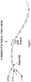
Figure 3 is a schematic illustration of target jetting locations (TJL), potential jetting locations (PJL) according to the invention and actual jetting locations (AJL), respectively. - We start by defining some concepts relevant to the invention, to enable clarity and consistent terminology. We then describe exemplary aspects of the invention in the Density correction section below.
- Inkjet printing systems contain multiple nozzles, forming arrangement of nozzles, which share a control signal indicating when to create actuation events. In inkjet printing, printheads contain multiple nozzles forming nozzle arrays, ranging from a single row of nozzles to large 2D arrays. Nozzle arrays share a common drive signal received from drive electronics. A separate or integrated controller provides data switching to the printhead that determines which of the individual nozzles are to jet ink for a given instance of the actuation event.
- A "print path" describes the movement of the arrangement of nozzles relative to a surface for printing. For example, a print path is the relative movement of a nozzle arrangement and the object (shape) during the printing process. A 'path' describes the plurality of locations on the surface which are to pass under a nozzle. Determining the path of an individual nozzle provides the locus the nozzle traces across the target surface. This relative motion is equivalent even if the arrangement of nozzles is static and the object moves, or both move providing a relative motion.
- In an example, full height printing of cone shapes has been developed. While known processes include correcting the position of drops so that they match the position of pixels in a "wrapped" source image, there remains a requirement to correct for the changing density of the output caused by varying surface geometry, as illustrated in
Figure 1 . - A print system comprises a printhead array receiving signals indicating when to create actuation events, and stripe data for groups of nozzles associated with shared actuation events. A nozzle of the printhead array moving along a flat surface is also referred to as a "flat nozzle". In this situation, each actuation event produces dots as deposits of fluid such as ink from driven nozzles of the printhead regularly spaced at the potential jetting locations 10 (where it is possible to place a dot) and thus achieving the target resolution (
Figure 1(a) ). The printed dots represent what we call 'actual jetting locations'. - When a nozzle is moving across a curved print path, at a different speed to that of another "flat" nozzle in the array, the distance between the actual jetting locations will differ from that achieved with the flat nozzle and thus the print density will be altered (as shown in
Figure 1 (b) ). Accordingly, density correction of the output for curved surfaces is needed to achieve the density that would be normally achieved during standard printing of flat surfaces. -
Figures 2 and3 each show a succession oftarget jetting locations 9 where we wish to place a dot and a succession of potential jetting locations 10 (corresponding to actuation events), where it is possible to place a dot. InFigure 2 , thepotential positions 10 are on the surface of a cone. - The actuation events at the
potential positions 10 may be controlled by way of a synchronisation element such as an encoder, clock or similar device. As shown schematically inFigures 2 and3 , the step size is adjusted by reducing the interval to obtain new potential jetting locations 10' from which actual jetting locations may be selected as a subset of the potential jetting locations, to be within the maximum error distance from the target jetting locations. - As each nozzle traces its print path, it achieves a velocity defined as the distance moved per unit interval. For an encoder based system, this would be a distance per encoder pulse, and for a clock based system, this would be a distance per unit time e.g. m/s. In order to limit the maximum error it is necessary to determine across all nozzles in the arrangement the maximum velocity attained by any nozzle during the relative movement of the arrangement and the surface.
- According to the invention therefore, density correction is performed by using a reduced interval I between the actuation events, whilst selecting carefully which nozzles jet for any particular event.
- By selecting an interval sufficiently small for the system, the maximum error distance between the
actual jetting locations 11 and the correspondingtarget jetting locations 9 for all the nozzles in the system may be limited to the defined maximum error distance. Hence the invention makes it possible to achieve a printed dot resolution arbitrarily close to the required dot resolution. Typically, the defined maximum error distance is set to be 10 to 20% of the target pitch. - This invention makes it possible to compensate for variations in dot resolution across arrangements of nozzles which share common actuation events, caused by the nozzles moving at variable speeds across curved surfaces. As will be apparent to one skilled in the art, the same technique may be applied to one or more such arrangements, e.g. to one or more nozzle arrays within a printhead, and to one or more printheads within a printing system.
- One cost of this approach is that the frequency of the actuation events (firing frequency) and swathe data are greater than if all the nozzles in the printhead array were being actuated at a single resolution for a given velocity. Accordingly, the chosen interval I represents a trade-off between the increased accuracy of drop placement achieved and productivity.
- Although the invention has been described in terms of examples related to inkjet printing systems for dispensing ink at target locations as set forth above, it should be understood that these examples are illustrative only. It will be appreciated that the invention may be used for controlling or operating deposition systems suitable for making any placements or dispensing, that is placing any object at target locations. For example, the method may apply to a system dispensing fertiliser or sowing seeds from a trailer as it is towed. The method is then advantageous when the trailer moves around the corner at the edge of a field in order to correct density of the deposited seeds.
Claims (10)
- A method of controlling a system comprising an arrangement of at least two nozzles, wherein said arrangement and a surface of an object move relative to each other, each nozzle traces a respective path on the surface of the object, and each nozzle is configured to jet drops at actual jetting locations along the respective path of said nozzle, the method comprising the steps of:defining, for each path traced by a nozzle, a plurality of target jetting locations regularly spaced by a target pitch;determining the maximum velocity any nozzle from said arrangement reaches along the respective path of said nozzle during the relative movement wherein the relative velocities are different for different nozzles of the at least two nozzles;defining an error distance associated with each target jetting location to be the distance between the said target jetting location and an actual jetting location which is closest to said target jetting location;setting a maximum value for the error distance, wherein the maximum value is greater than zero;providing a first control signal comprising a sequence of actuation events for said arrangement, wherein said first control signal is common to all nozzles in said arrangement, wherein the sequence of actuation events corresponds to a sequence of potential jetting locations for each nozzle along the path traced by said nozzle, wherein the actuation events are provided at a regular interval, said interval being chosen so that a maximum distance between consecutive potential jetting locations for all nozzles is limited to twice the maximum value for the error distance in the actual jetting location, wherein the maximum distance is the said interval multiplied by said maximum velocity;for each nozzle, choosing a subset of the potential jetting locations which is the set of actual jetting locations for said nozzle wherein for each target jetting location of that nozzle there is an actual jetting location in said set that is closer to said target jetting location than the maximum value for the error distance; anddetermining, for each actuation event in the sequence of actuation events, the subset of nozzles from the arrangement wherein each nozzle is at an actual jetting location from the set of actual jetting locations for said nozzle.
- A method according to claim 1, wherein the maximum value of the error distance is less than half the target pitch.
- A method according to claim 2, wherein the maximum value of the error distance is between 10% and 20% of the target pitch.
- A method according to any preceding claim, the method further comprising the steps of: providing image data for each actual jetting location, and providing a second control signal to said arrangement of at least two nozzles to jet drops according to the image data.
- A method according to any preceding claim, wherein said method steps are carried out for a first relative movement with a first maximum velocity and a first interval, the method steps then repeated for a second relative movement with a second maximum velocity different to the first maximum velocity and with a second interval different to the first interval.
- A method according to any preceding claim, wherein the step of choosing a subset of the potential jetting locations comprises identifying an actual jetting location in said set that is closest to said target jetting location.
- A method according to any preceding claim, wherein in the step of defining, for each path traced by a nozzle, a plurality of target jetting locations regularly spaced by a target pitch: a position of the first target jetting location is set within a distance from the start of said path equal to the target pitch, wherein said distance is varied between paths according to a random distribution.
- A method according to any preceding claim, wherein the method further comprises the step of providing a synchronisation element for coordinating the control signal with said movement of the arrangement relative to the surface of the object.
- A control system for an arrangement of at least two nozzles, wherein said arrangement and a surface of an object are moveable relative to each other, each nozzle being configured to trace a respective path on the surface of the object, and configured to jet drops at actual jetting locations along the respective path of said nozzle, the system comprising a processor configured to:define, for each path to be traced by a nozzle, a plurality of target jetting locations regularly spaced by a target pitch;determine the maximum velocity any nozzle from said arrangement reaches along the respective path of said nozzle during the relative movement wherein the relative velocities are different for different nozzles of the at least two nozzles;define an error distance associated with each target jetting location to be the distance between the said target jetting location and an actual jetting location which is closest to said target jetting location;set a maximum value for the error distance, wherein the maximum value is greater than zero;provide a first control signal comprising a sequence of actuation events for said arrangement, wherein said first control signal is common to all nozzles in said arrangement, wherein the sequence of actuation events corresponds to a sequence of potential jetting locations for each nozzle along the path traced by said nozzle, wherein the actuation events are provided at a regular interval, said interval being chosen so that a maximum distance between consecutive potential jetting locations for all nozzles is limited to twice the maximum value for the error distance in the actual jetting location, wherein the maximum distance is the said interval multiplied by said maximum velocity;for each nozzle, choose a subset of the potential jetting locations which is the set of actual jetting locations for said nozzle wherein for each target jetting location of that nozzle there is an actual jetting location in said set that is closer to said target jetting location than the maximum value for the error distance; anddetermine, for each actuation event in the sequence of actuation events, the subset of nozzles from said arrangement wherein each nozzle is at an actual jetting location from the set of actual jetting locations for said nozzle.
- A printing system comprising a control system according to claim 9.
Applications Claiming Priority (2)
| Application Number | Priority Date | Filing Date | Title |
|---|---|---|---|
| GB1818679.1A GB2579050B (en) | 2018-11-16 | 2018-11-16 | Control methods and systems |
| PCT/GB2019/052594 WO2020099820A1 (en) | 2018-11-16 | 2019-09-16 | Control methods and systems |
Publications (2)
| Publication Number | Publication Date |
|---|---|
| EP3826857A1 EP3826857A1 (en) | 2021-06-02 |
| EP3826857B1 true EP3826857B1 (en) | 2021-12-15 |
Family
ID=64739987
Family Applications (1)
| Application Number | Title | Priority Date | Filing Date |
|---|---|---|---|
| EP19772814.0A Active EP3826857B1 (en) | 2018-11-16 | 2019-09-16 | Control methods and systems |
Country Status (9)
| Country | Link |
|---|---|
| US (1) | US11780239B2 (en) |
| EP (1) | EP3826857B1 (en) |
| JP (1) | JP7541514B2 (en) |
| KR (1) | KR102806988B1 (en) |
| CN (1) | CN113767015B (en) |
| ES (1) | ES2901640T3 (en) |
| GB (1) | GB2579050B (en) |
| IL (1) | IL283150B2 (en) |
| WO (1) | WO2020099820A1 (en) |
Families Citing this family (1)
| Publication number | Priority date | Publication date | Assignee | Title |
|---|---|---|---|---|
| GB2579050B (en) | 2018-11-16 | 2021-12-01 | Global Inkjet Systems Ltd | Control methods and systems |
Family Cites Families (23)
| Publication number | Priority date | Publication date | Assignee | Title |
|---|---|---|---|---|
| US6360656B2 (en) * | 2000-02-28 | 2002-03-26 | Minolta Co., Ltd. | Apparatus for and method of printing on three-dimensional object |
| US6460958B2 (en) * | 2000-02-29 | 2002-10-08 | Minolta Co., Ltd. | Three-dimensional object printing apparatus and method |
| GB2376920A (en) * | 2001-06-27 | 2002-12-31 | Inca Digital Printers Ltd | Inkjet printing on a three-dimensional object including relative movement of a printhead and the object during printing about a rotational axis |
| US6814425B2 (en) * | 2002-04-12 | 2004-11-09 | Hewlett-Packard Development Company, L.P. | Droplet placement onto surfaces |
| CN100361816C (en) * | 2003-12-22 | 2008-01-16 | 雅马哈株式会社 | System and method for printing image pattern on object |
| US7380911B2 (en) * | 2004-05-10 | 2008-06-03 | Eastman Kodak Company | Jet printer with enhanced print drop delivery |
| US8167393B2 (en) * | 2005-01-14 | 2012-05-01 | Cabot Corporation | Printable electronic features on non-uniform substrate and processes for making same |
| DE102007021767A1 (en) * | 2007-05-09 | 2008-11-13 | Bauer, Jörg R. | Method and device for printing a component with two mutually inclined surface areas by means of a digital printing method |
| EP2229282A1 (en) * | 2007-12-31 | 2010-09-22 | Exatec, LLC. | Apparatus and method for printing three-dimensional articles |
| AT509149A3 (en) * | 2009-11-27 | 2012-03-15 | Durst Phototechnik Digital Technology Gmbh | METHOD FOR ADAPTIVELY ADAPTING THE VOLUME FLOW OF THE EMITTED INK |
| JP5728828B2 (en) * | 2010-05-10 | 2015-06-03 | セイコーエプソン株式会社 | Liquid ejector |
| EP2433716A1 (en) * | 2010-09-22 | 2012-03-28 | Hexagon Technology Center GmbH | Surface spraying device with a nozzle control mechanism and a corresponding method |
| CN105058985B (en) * | 2010-10-01 | 2016-10-05 | 马姆杰特科技有限公司 | By can independent actuation chamber top oar control ink droplet directivity inkjet nozzle assembly |
| JP5494562B2 (en) * | 2011-04-28 | 2014-05-14 | カシオ計算機株式会社 | Curved surface printing apparatus and printing control method for curved surface printing apparatus |
| DE102011086015A1 (en) * | 2011-11-09 | 2013-05-16 | Krones Aktiengesellschaft | Method and apparatus for ink jet printing on curved object surfaces |
| DE102012005924A1 (en) * | 2012-03-26 | 2013-09-26 | Khs Gmbh | Method and an arrangement for printing a surface |
| DE102012006370A1 (en) * | 2012-03-29 | 2013-10-02 | Heidelberger Druckmaschinen Aktiengesellschaft | System for printing on an object |
| WO2014092678A1 (en) * | 2012-12-10 | 2014-06-19 | Hewlett-Packard Development Company, L. P. | Fluid drop detection in firing paths corresponding to nozzles of a printhead |
| US8842331B1 (en) * | 2013-03-25 | 2014-09-23 | Eastman Kodak Company | Multi-print head printer for detecting alignment errors and aligning image data reducing swath boundaries |
| CN103722886A (en) * | 2013-12-25 | 2014-04-16 | 汤振华 | Surface airbrushing method and airbrushing head for stereoscopic object |
| JP6740035B2 (en) * | 2016-06-30 | 2020-08-12 | 独立行政法人国立高等専門学校機構 | Printing apparatus, printing apparatus control method, and printing method |
| WO2018140043A1 (en) * | 2017-01-27 | 2018-08-02 | Hewlett-Packard Development Company, L.P. | Controlling printing fluid drop ejection |
| GB2579050B (en) | 2018-11-16 | 2021-12-01 | Global Inkjet Systems Ltd | Control methods and systems |
-
2018
- 2018-11-16 GB GB1818679.1A patent/GB2579050B/en active Active
-
2019
- 2019-09-16 WO PCT/GB2019/052594 patent/WO2020099820A1/en not_active Ceased
- 2019-09-16 IL IL283150A patent/IL283150B2/en unknown
- 2019-09-16 EP EP19772814.0A patent/EP3826857B1/en active Active
- 2019-09-16 KR KR1020217018283A patent/KR102806988B1/en active Active
- 2019-09-16 CN CN201980067642.4A patent/CN113767015B/en active Active
- 2019-09-16 JP JP2021526688A patent/JP7541514B2/en active Active
- 2019-09-16 ES ES19772814T patent/ES2901640T3/en active Active
-
2021
- 2021-05-13 US US17/319,648 patent/US11780239B2/en active Active
Also Published As
| Publication number | Publication date |
|---|---|
| CN113767015A (en) | 2021-12-07 |
| JP2022519417A (en) | 2022-03-24 |
| IL283150A (en) | 2021-06-30 |
| KR102806988B1 (en) | 2025-05-14 |
| ES2901640T3 (en) | 2022-03-23 |
| WO2020099820A1 (en) | 2020-05-22 |
| US11780239B2 (en) | 2023-10-10 |
| GB201818679D0 (en) | 2019-01-02 |
| GB2579050A (en) | 2020-06-10 |
| EP3826857A1 (en) | 2021-06-02 |
| CN113767015B (en) | 2022-09-30 |
| GB2579050B (en) | 2021-12-01 |
| JP7541514B2 (en) | 2024-08-28 |
| KR20210093299A (en) | 2021-07-27 |
| US20210347168A1 (en) | 2021-11-11 |
| IL283150B2 (en) | 2026-02-01 |
| IL283150B1 (en) | 2025-10-01 |
Similar Documents
| Publication | Publication Date | Title |
|---|---|---|
| US11633961B2 (en) | Printing methods and systems | |
| US10214008B2 (en) | Circuit for driving printer actuating elements | |
| US11780239B2 (en) | Control methods and systems | |
| US12043045B2 (en) | Stitching methods and systems | |
| KR100984569B1 (en) | System and method for manufacturing color filter using pattern data, control device and manufacturing method of the system | |
| EP1935653B1 (en) | Adjustment of print arrays in a printing device | |
| US11529804B2 (en) | Inkjet printing method |
Legal Events
| Date | Code | Title | Description |
|---|---|---|---|
| STAA | Information on the status of an ep patent application or granted ep patent |
Free format text: STATUS: UNKNOWN |
|
| STAA | Information on the status of an ep patent application or granted ep patent |
Free format text: STATUS: THE INTERNATIONAL PUBLICATION HAS BEEN MADE |
|
| PUAI | Public reference made under article 153(3) epc to a published international application that has entered the european phase |
Free format text: ORIGINAL CODE: 0009012 |
|
| STAA | Information on the status of an ep patent application or granted ep patent |
Free format text: STATUS: REQUEST FOR EXAMINATION WAS MADE |
|
| 17P | Request for examination filed |
Effective date: 20210225 |
|
| AK | Designated contracting states |
Kind code of ref document: A1 Designated state(s): AL AT BE BG CH CY CZ DE DK EE ES FI FR GB GR HR HU IE IS IT LI LT LU LV MC MK MT NL NO PL PT RO RS SE SI SK SM TR |
|
| GRAP | Despatch of communication of intention to grant a patent |
Free format text: ORIGINAL CODE: EPIDOSNIGR1 |
|
| STAA | Information on the status of an ep patent application or granted ep patent |
Free format text: STATUS: GRANT OF PATENT IS INTENDED |
|
| RIC1 | Information provided on ipc code assigned before grant |
Ipc: B41J 2/21 20060101ALI20210916BHEP Ipc: H04N 1/407 20060101ALI20210916BHEP Ipc: G06K 15/02 20060101ALI20210916BHEP Ipc: B41J 2/045 20060101ALI20210916BHEP Ipc: B41F 17/28 20060101ALI20210916BHEP Ipc: B41M 5/00 20060101ALI20210916BHEP Ipc: H04N 1/401 20060101ALI20210916BHEP Ipc: B41J 3/407 20060101AFI20210916BHEP |
|
| GRAS | Grant fee paid |
Free format text: ORIGINAL CODE: EPIDOSNIGR3 |
|
| GRAA | (expected) grant |
Free format text: ORIGINAL CODE: 0009210 |
|
| STAA | Information on the status of an ep patent application or granted ep patent |
Free format text: STATUS: THE PATENT HAS BEEN GRANTED |
|
| INTG | Intention to grant announced |
Effective date: 20211018 |
|
| AK | Designated contracting states |
Kind code of ref document: B1 Designated state(s): AL AT BE BG CH CY CZ DE DK EE ES FI FR GR HR HU IE IS IT LI LT LU LV MC MK MT NL NO PL PT RO RS SE SI SK SM TR |
|
| DAV | Request for validation of the european patent (deleted) | ||
| DAX | Request for extension of the european patent (deleted) | ||
| RBV | Designated contracting states (corrected) |
Designated state(s): AL AT BE BG CH CY CZ DE DK EE ES FI FR GR HR HU IE IS IT LI LT LU LV MC MK MT NL NO PL PT RO RS SE SI SK SM TR |
|
| REG | Reference to a national code |
Ref country code: CH Ref legal event code: EP |
|
| REG | Reference to a national code |
Ref country code: DE Ref legal event code: R096 Ref document number: 602019010140 Country of ref document: DE |
|
| REG | Reference to a national code |
Ref country code: IE Ref legal event code: FG4D |
|
| REG | Reference to a national code |
Ref country code: AT Ref legal event code: REF Ref document number: 1455206 Country of ref document: AT Kind code of ref document: T Effective date: 20220115 |
|
| REG | Reference to a national code |
Ref country code: NL Ref legal event code: FP |
|
| REG | Reference to a national code |
Ref country code: ES Ref legal event code: FG2A Ref document number: 2901640 Country of ref document: ES Kind code of ref document: T3 Effective date: 20220323 |
|
| REG | Reference to a national code |
Ref country code: LT Ref legal event code: MG9D |
|
| PG25 | Lapsed in a contracting state [announced via postgrant information from national office to epo] |
Ref country code: RS Free format text: LAPSE BECAUSE OF FAILURE TO SUBMIT A TRANSLATION OF THE DESCRIPTION OR TO PAY THE FEE WITHIN THE PRESCRIBED TIME-LIMIT Effective date: 20211215 Ref country code: LT Free format text: LAPSE BECAUSE OF FAILURE TO SUBMIT A TRANSLATION OF THE DESCRIPTION OR TO PAY THE FEE WITHIN THE PRESCRIBED TIME-LIMIT Effective date: 20211215 Ref country code: FI Free format text: LAPSE BECAUSE OF FAILURE TO SUBMIT A TRANSLATION OF THE DESCRIPTION OR TO PAY THE FEE WITHIN THE PRESCRIBED TIME-LIMIT Effective date: 20211215 Ref country code: BG Free format text: LAPSE BECAUSE OF FAILURE TO SUBMIT A TRANSLATION OF THE DESCRIPTION OR TO PAY THE FEE WITHIN THE PRESCRIBED TIME-LIMIT Effective date: 20220315 |
|
| REG | Reference to a national code |
Ref country code: AT Ref legal event code: MK05 Ref document number: 1455206 Country of ref document: AT Kind code of ref document: T Effective date: 20211215 |
|
| PG25 | Lapsed in a contracting state [announced via postgrant information from national office to epo] |
Ref country code: SE Free format text: LAPSE BECAUSE OF FAILURE TO SUBMIT A TRANSLATION OF THE DESCRIPTION OR TO PAY THE FEE WITHIN THE PRESCRIBED TIME-LIMIT Effective date: 20211215 Ref country code: NO Free format text: LAPSE BECAUSE OF FAILURE TO SUBMIT A TRANSLATION OF THE DESCRIPTION OR TO PAY THE FEE WITHIN THE PRESCRIBED TIME-LIMIT Effective date: 20220315 Ref country code: LV Free format text: LAPSE BECAUSE OF FAILURE TO SUBMIT A TRANSLATION OF THE DESCRIPTION OR TO PAY THE FEE WITHIN THE PRESCRIBED TIME-LIMIT Effective date: 20211215 Ref country code: HR Free format text: LAPSE BECAUSE OF FAILURE TO SUBMIT A TRANSLATION OF THE DESCRIPTION OR TO PAY THE FEE WITHIN THE PRESCRIBED TIME-LIMIT Effective date: 20211215 Ref country code: GR Free format text: LAPSE BECAUSE OF FAILURE TO SUBMIT A TRANSLATION OF THE DESCRIPTION OR TO PAY THE FEE WITHIN THE PRESCRIBED TIME-LIMIT Effective date: 20220316 |
|
| PG25 | Lapsed in a contracting state [announced via postgrant information from national office to epo] |
Ref country code: SM Free format text: LAPSE BECAUSE OF FAILURE TO SUBMIT A TRANSLATION OF THE DESCRIPTION OR TO PAY THE FEE WITHIN THE PRESCRIBED TIME-LIMIT Effective date: 20211215 Ref country code: SK Free format text: LAPSE BECAUSE OF FAILURE TO SUBMIT A TRANSLATION OF THE DESCRIPTION OR TO PAY THE FEE WITHIN THE PRESCRIBED TIME-LIMIT Effective date: 20211215 Ref country code: RO Free format text: LAPSE BECAUSE OF FAILURE TO SUBMIT A TRANSLATION OF THE DESCRIPTION OR TO PAY THE FEE WITHIN THE PRESCRIBED TIME-LIMIT Effective date: 20211215 Ref country code: PT Free format text: LAPSE BECAUSE OF FAILURE TO SUBMIT A TRANSLATION OF THE DESCRIPTION OR TO PAY THE FEE WITHIN THE PRESCRIBED TIME-LIMIT Effective date: 20220418 Ref country code: EE Free format text: LAPSE BECAUSE OF FAILURE TO SUBMIT A TRANSLATION OF THE DESCRIPTION OR TO PAY THE FEE WITHIN THE PRESCRIBED TIME-LIMIT Effective date: 20211215 Ref country code: CZ Free format text: LAPSE BECAUSE OF FAILURE TO SUBMIT A TRANSLATION OF THE DESCRIPTION OR TO PAY THE FEE WITHIN THE PRESCRIBED TIME-LIMIT Effective date: 20211215 |
|
| PG25 | Lapsed in a contracting state [announced via postgrant information from national office to epo] |
Ref country code: PL Free format text: LAPSE BECAUSE OF FAILURE TO SUBMIT A TRANSLATION OF THE DESCRIPTION OR TO PAY THE FEE WITHIN THE PRESCRIBED TIME-LIMIT Effective date: 20211215 Ref country code: AT Free format text: LAPSE BECAUSE OF FAILURE TO SUBMIT A TRANSLATION OF THE DESCRIPTION OR TO PAY THE FEE WITHIN THE PRESCRIBED TIME-LIMIT Effective date: 20211215 |
|
| REG | Reference to a national code |
Ref country code: DE Ref legal event code: R097 Ref document number: 602019010140 Country of ref document: DE |
|
| PG25 | Lapsed in a contracting state [announced via postgrant information from national office to epo] |
Ref country code: IS Free format text: LAPSE BECAUSE OF FAILURE TO SUBMIT A TRANSLATION OF THE DESCRIPTION OR TO PAY THE FEE WITHIN THE PRESCRIBED TIME-LIMIT Effective date: 20220415 |
|
| PLBE | No opposition filed within time limit |
Free format text: ORIGINAL CODE: 0009261 |
|
| STAA | Information on the status of an ep patent application or granted ep patent |
Free format text: STATUS: NO OPPOSITION FILED WITHIN TIME LIMIT |
|
| PG25 | Lapsed in a contracting state [announced via postgrant information from national office to epo] |
Ref country code: DK Free format text: LAPSE BECAUSE OF FAILURE TO SUBMIT A TRANSLATION OF THE DESCRIPTION OR TO PAY THE FEE WITHIN THE PRESCRIBED TIME-LIMIT Effective date: 20211215 Ref country code: AL Free format text: LAPSE BECAUSE OF FAILURE TO SUBMIT A TRANSLATION OF THE DESCRIPTION OR TO PAY THE FEE WITHIN THE PRESCRIBED TIME-LIMIT Effective date: 20211215 |
|
| 26N | No opposition filed |
Effective date: 20220916 |
|
| PG25 | Lapsed in a contracting state [announced via postgrant information from national office to epo] |
Ref country code: MC Free format text: LAPSE BECAUSE OF FAILURE TO SUBMIT A TRANSLATION OF THE DESCRIPTION OR TO PAY THE FEE WITHIN THE PRESCRIBED TIME-LIMIT Effective date: 20211215 |
|
| REG | Reference to a national code |
Ref country code: BE Ref legal event code: MM Effective date: 20220930 |
|
| PG25 | Lapsed in a contracting state [announced via postgrant information from national office to epo] |
Ref country code: LU Free format text: LAPSE BECAUSE OF NON-PAYMENT OF DUE FEES Effective date: 20220916 |
|
| P01 | Opt-out of the competence of the unified patent court (upc) registered |
Effective date: 20230530 |
|
| PG25 | Lapsed in a contracting state [announced via postgrant information from national office to epo] |
Ref country code: IE Free format text: LAPSE BECAUSE OF NON-PAYMENT OF DUE FEES Effective date: 20220916 |
|
| PG25 | Lapsed in a contracting state [announced via postgrant information from national office to epo] |
Ref country code: BE Free format text: LAPSE BECAUSE OF NON-PAYMENT OF DUE FEES Effective date: 20220930 |
|
| PG25 | Lapsed in a contracting state [announced via postgrant information from national office to epo] |
Ref country code: CY Free format text: LAPSE BECAUSE OF FAILURE TO SUBMIT A TRANSLATION OF THE DESCRIPTION OR TO PAY THE FEE WITHIN THE PRESCRIBED TIME-LIMIT Effective date: 20211215 |
|
| PG25 | Lapsed in a contracting state [announced via postgrant information from national office to epo] |
Ref country code: MK Free format text: LAPSE BECAUSE OF FAILURE TO SUBMIT A TRANSLATION OF THE DESCRIPTION OR TO PAY THE FEE WITHIN THE PRESCRIBED TIME-LIMIT Effective date: 20211215 Ref country code: HU Free format text: LAPSE BECAUSE OF FAILURE TO SUBMIT A TRANSLATION OF THE DESCRIPTION OR TO PAY THE FEE WITHIN THE PRESCRIBED TIME-LIMIT; INVALID AB INITIO Effective date: 20190916 |
|
| PG25 | Lapsed in a contracting state [announced via postgrant information from national office to epo] |
Ref country code: TR Free format text: LAPSE BECAUSE OF FAILURE TO SUBMIT A TRANSLATION OF THE DESCRIPTION OR TO PAY THE FEE WITHIN THE PRESCRIBED TIME-LIMIT Effective date: 20211215 |
|
| PGFP | Annual fee paid to national office [announced via postgrant information from national office to epo] |
Ref country code: NL Payment date: 20240814 Year of fee payment: 6 |
|
| PG25 | Lapsed in a contracting state [announced via postgrant information from national office to epo] |
Ref country code: MT Free format text: LAPSE BECAUSE OF FAILURE TO SUBMIT A TRANSLATION OF THE DESCRIPTION OR TO PAY THE FEE WITHIN THE PRESCRIBED TIME-LIMIT Effective date: 20211215 |
|
| PGFP | Annual fee paid to national office [announced via postgrant information from national office to epo] |
Ref country code: IT Payment date: 20240903 Year of fee payment: 6 |
|
| PGFP | Annual fee paid to national office [announced via postgrant information from national office to epo] |
Ref country code: ES Payment date: 20241003 Year of fee payment: 6 |
|
| PGFP | Annual fee paid to national office [announced via postgrant information from national office to epo] |
Ref country code: CH Payment date: 20241001 Year of fee payment: 6 |
|
| PG25 | Lapsed in a contracting state [announced via postgrant information from national office to epo] |
Ref country code: SI Free format text: LAPSE BECAUSE OF FAILURE TO SUBMIT A TRANSLATION OF THE DESCRIPTION OR TO PAY THE FEE WITHIN THE PRESCRIBED TIME-LIMIT Effective date: 20211215 |
|
| PGFP | Annual fee paid to national office [announced via postgrant information from national office to epo] |
Ref country code: DE Payment date: 20260304 Year of fee payment: 7 |
|
| PGFP | Annual fee paid to national office [announced via postgrant information from national office to epo] |
Ref country code: FR Payment date: 20260304 Year of fee payment: 7 |
|
| REG | Reference to a national code |
Ref country code: CH Ref legal event code: H13 Free format text: ST27 STATUS EVENT CODE: U-0-0-H10-H13 (AS PROVIDED BY THE NATIONAL OFFICE) Effective date: 20260504 |
|
| REG | Reference to a national code |
Ref country code: NL Ref legal event code: MM Effective date: 20251001 |
|
| PG25 | Lapsed in a contracting state [announced via postgrant information from national office to epo] |
Ref country code: NL Free format text: LAPSE BECAUSE OF NON-PAYMENT OF DUE FEES Effective date: 20251001 |
|
| PG25 | Lapsed in a contracting state [announced via postgrant information from national office to epo] |
Ref country code: IT Free format text: LAPSE BECAUSE OF NON-PAYMENT OF DUE FEES Effective date: 20250916 |
|
| PG25 | Lapsed in a contracting state [announced via postgrant information from national office to epo] |
Ref country code: CH Free format text: LAPSE BECAUSE OF NON-PAYMENT OF DUE FEES Effective date: 20250930 |