EP3826756B1 - Static mixer for exhaust gas ducts of internal combustion engines and exhaust unit incorporating the mixer - Google Patents
Static mixer for exhaust gas ducts of internal combustion engines and exhaust unit incorporating the mixer Download PDFInfo
- Publication number
- EP3826756B1 EP3826756B1 EP19759050.8A EP19759050A EP3826756B1 EP 3826756 B1 EP3826756 B1 EP 3826756B1 EP 19759050 A EP19759050 A EP 19759050A EP 3826756 B1 EP3826756 B1 EP 3826756B1
- Authority
- EP
- European Patent Office
- Prior art keywords
- mixer
- gases
- exhaust gas
- mouth
- symmetry axis
- Prior art date
- Legal status (The legal status is an assumption and is not a legal conclusion. Google has not performed a legal analysis and makes no representation as to the accuracy of the status listed.)
- Active
Links
Images






Classifications
-
- B—PERFORMING OPERATIONS; TRANSPORTING
- B01—PHYSICAL OR CHEMICAL PROCESSES OR APPARATUS IN GENERAL
- B01F—MIXING, e.g. DISSOLVING, EMULSIFYING OR DISPERSING
- B01F23/00—Mixing according to the phases to be mixed, e.g. dispersing or emulsifying
- B01F23/20—Mixing gases with liquids
- B01F23/21—Mixing gases with liquids by introducing liquids into gaseous media
- B01F23/213—Mixing gases with liquids by introducing liquids into gaseous media by spraying or atomising of the liquids
- B01F23/2132—Mixing gases with liquids by introducing liquids into gaseous media by spraying or atomising of the liquids using nozzles
-
- B—PERFORMING OPERATIONS; TRANSPORTING
- B01—PHYSICAL OR CHEMICAL PROCESSES OR APPARATUS IN GENERAL
- B01F—MIXING, e.g. DISSOLVING, EMULSIFYING OR DISPERSING
- B01F25/00—Flow mixers; Mixers for falling materials, e.g. solid particles
- B01F25/30—Injector mixers
- B01F25/31—Injector mixers in conduits or tubes through which the main component flows
- B01F25/314—Injector mixers in conduits or tubes through which the main component flows wherein additional components are introduced at the circumference of the conduit
- B01F25/3141—Injector mixers in conduits or tubes through which the main component flows wherein additional components are introduced at the circumference of the conduit with additional mixing means other than injector mixers
-
- B—PERFORMING OPERATIONS; TRANSPORTING
- B01—PHYSICAL OR CHEMICAL PROCESSES OR APPARATUS IN GENERAL
- B01F—MIXING, e.g. DISSOLVING, EMULSIFYING OR DISPERSING
- B01F25/00—Flow mixers; Mixers for falling materials, e.g. solid particles
- B01F25/40—Static mixers
- B01F25/42—Static mixers in which the mixing is affected by moving the components jointly in changing directions, e.g. in tubes provided with baffles or obstructions
- B01F25/43—Mixing tubes, e.g. wherein the material is moved in a radial or partly reversed direction
- B01F25/431—Straight mixing tubes with baffles or obstructions that do not cause substantial pressure drop; Baffles therefor
- B01F25/4315—Straight mixing tubes with baffles or obstructions that do not cause substantial pressure drop; Baffles therefor the baffles being deformed flat pieces of material
-
- F—MECHANICAL ENGINEERING; LIGHTING; HEATING; WEAPONS; BLASTING
- F01—MACHINES OR ENGINES IN GENERAL; ENGINE PLANTS IN GENERAL; STEAM ENGINES
- F01N—GAS-FLOW SILENCERS OR EXHAUST APPARATUS FOR MACHINES OR ENGINES IN GENERAL; GAS-FLOW SILENCERS OR EXHAUST APPARATUS FOR INTERNAL-COMBUSTION ENGINES
- F01N13/00—Exhaust or silencing apparatus characterised by constructional features
- F01N13/009—Exhaust or silencing apparatus characterised by constructional features having two or more separate purifying devices arranged in series
-
- F—MECHANICAL ENGINEERING; LIGHTING; HEATING; WEAPONS; BLASTING
- F01—MACHINES OR ENGINES IN GENERAL; ENGINE PLANTS IN GENERAL; STEAM ENGINES
- F01N—GAS-FLOW SILENCERS OR EXHAUST APPARATUS FOR MACHINES OR ENGINES IN GENERAL; GAS-FLOW SILENCERS OR EXHAUST APPARATUS FOR INTERNAL-COMBUSTION ENGINES
- F01N3/00—Exhaust or silencing apparatus having means for purifying, rendering innocuous, or otherwise treating exhaust
- F01N3/02—Exhaust or silencing apparatus having means for purifying, rendering innocuous, or otherwise treating exhaust for cooling, or for removing solid constituents of, exhaust
- F01N3/021—Exhaust or silencing apparatus having means for purifying, rendering innocuous, or otherwise treating exhaust for cooling, or for removing solid constituents of, exhaust by means of filters
- F01N3/033—Exhaust or silencing apparatus having means for purifying, rendering innocuous, or otherwise treating exhaust for cooling, or for removing solid constituents of, exhaust by means of filters in combination with other devices
- F01N3/035—Exhaust or silencing apparatus having means for purifying, rendering innocuous, or otherwise treating exhaust for cooling, or for removing solid constituents of, exhaust by means of filters in combination with other devices with catalytic reactors
-
- F—MECHANICAL ENGINEERING; LIGHTING; HEATING; WEAPONS; BLASTING
- F01—MACHINES OR ENGINES IN GENERAL; ENGINE PLANTS IN GENERAL; STEAM ENGINES
- F01N—GAS-FLOW SILENCERS OR EXHAUST APPARATUS FOR MACHINES OR ENGINES IN GENERAL; GAS-FLOW SILENCERS OR EXHAUST APPARATUS FOR INTERNAL-COMBUSTION ENGINES
- F01N3/00—Exhaust or silencing apparatus having means for purifying, rendering innocuous, or otherwise treating exhaust
- F01N3/08—Exhaust or silencing apparatus having means for purifying, rendering innocuous, or otherwise treating exhaust for rendering innocuous
- F01N3/10—Exhaust or silencing apparatus having means for purifying, rendering innocuous, or otherwise treating exhaust for rendering innocuous by thermal or catalytic conversion of noxious components of exhaust
- F01N3/18—Exhaust or silencing apparatus having means for purifying, rendering innocuous, or otherwise treating exhaust for rendering innocuous by thermal or catalytic conversion of noxious components of exhaust characterised by methods of operation; Control
- F01N3/20—Exhaust or silencing apparatus having means for purifying, rendering innocuous, or otherwise treating exhaust for rendering innocuous by thermal or catalytic conversion of noxious components of exhaust characterised by methods of operation; Control specially adapted for catalytic conversion
- F01N3/206—Adding periodically or continuously substances to exhaust gases for promoting purification, e.g. catalytic material in liquid form, NOx reducing agents
- F01N3/2066—Selective catalytic reduction [SCR]
-
- F—MECHANICAL ENGINEERING; LIGHTING; HEATING; WEAPONS; BLASTING
- F01—MACHINES OR ENGINES IN GENERAL; ENGINE PLANTS IN GENERAL; STEAM ENGINES
- F01N—GAS-FLOW SILENCERS OR EXHAUST APPARATUS FOR MACHINES OR ENGINES IN GENERAL; GAS-FLOW SILENCERS OR EXHAUST APPARATUS FOR INTERNAL-COMBUSTION ENGINES
- F01N3/00—Exhaust or silencing apparatus having means for purifying, rendering innocuous, or otherwise treating exhaust
- F01N3/08—Exhaust or silencing apparatus having means for purifying, rendering innocuous, or otherwise treating exhaust for rendering innocuous
- F01N3/10—Exhaust or silencing apparatus having means for purifying, rendering innocuous, or otherwise treating exhaust for rendering innocuous by thermal or catalytic conversion of noxious components of exhaust
- F01N3/24—Exhaust or silencing apparatus having means for purifying, rendering innocuous, or otherwise treating exhaust for rendering innocuous by thermal or catalytic conversion of noxious components of exhaust characterised by constructional aspects of converting apparatus
- F01N3/28—Construction of catalytic reactors
- F01N3/2892—Exhaust flow directors or the like, e.g. upstream of catalytic device
-
- B—PERFORMING OPERATIONS; TRANSPORTING
- B01—PHYSICAL OR CHEMICAL PROCESSES OR APPARATUS IN GENERAL
- B01F—MIXING, e.g. DISSOLVING, EMULSIFYING OR DISPERSING
- B01F25/00—Flow mixers; Mixers for falling materials, e.g. solid particles
- B01F2025/91—Direction of flow or arrangement of feed and discharge openings
- B01F2025/913—Vortex flow, i.e. flow spiraling in a tangential direction and moving in an axial direction
-
- B—PERFORMING OPERATIONS; TRANSPORTING
- B01—PHYSICAL OR CHEMICAL PROCESSES OR APPARATUS IN GENERAL
- B01F—MIXING, e.g. DISSOLVING, EMULSIFYING OR DISPERSING
- B01F25/00—Flow mixers; Mixers for falling materials, e.g. solid particles
- B01F2025/93—Arrangements, nature or configuration of flow guiding elements
- B01F2025/931—Flow guiding elements surrounding feed openings, e.g. jet nozzles
-
- F—MECHANICAL ENGINEERING; LIGHTING; HEATING; WEAPONS; BLASTING
- F01—MACHINES OR ENGINES IN GENERAL; ENGINE PLANTS IN GENERAL; STEAM ENGINES
- F01N—GAS-FLOW SILENCERS OR EXHAUST APPARATUS FOR MACHINES OR ENGINES IN GENERAL; GAS-FLOW SILENCERS OR EXHAUST APPARATUS FOR INTERNAL-COMBUSTION ENGINES
- F01N2240/00—Combination or association of two or more different exhaust treating devices, or of at least one such device with an auxiliary device, not covered by indexing codes F01N2230/00 or F01N2250/00, one of the devices being
- F01N2240/20—Combination or association of two or more different exhaust treating devices, or of at least one such device with an auxiliary device, not covered by indexing codes F01N2230/00 or F01N2250/00, one of the devices being a flow director or deflector
-
- F—MECHANICAL ENGINEERING; LIGHTING; HEATING; WEAPONS; BLASTING
- F01—MACHINES OR ENGINES IN GENERAL; ENGINE PLANTS IN GENERAL; STEAM ENGINES
- F01N—GAS-FLOW SILENCERS OR EXHAUST APPARATUS FOR MACHINES OR ENGINES IN GENERAL; GAS-FLOW SILENCERS OR EXHAUST APPARATUS FOR INTERNAL-COMBUSTION ENGINES
- F01N2470/00—Structure or shape of exhaust gas passages, pipes or tubes
- F01N2470/02—Tubes being perforated
- F01N2470/04—Tubes being perforated characterised by shape, disposition or dimensions of apertures
-
- F—MECHANICAL ENGINEERING; LIGHTING; HEATING; WEAPONS; BLASTING
- F01—MACHINES OR ENGINES IN GENERAL; ENGINE PLANTS IN GENERAL; STEAM ENGINES
- F01N—GAS-FLOW SILENCERS OR EXHAUST APPARATUS FOR MACHINES OR ENGINES IN GENERAL; GAS-FLOW SILENCERS OR EXHAUST APPARATUS FOR INTERNAL-COMBUSTION ENGINES
- F01N2610/00—Adding substances to exhaust gases
-
- F—MECHANICAL ENGINEERING; LIGHTING; HEATING; WEAPONS; BLASTING
- F01—MACHINES OR ENGINES IN GENERAL; ENGINE PLANTS IN GENERAL; STEAM ENGINES
- F01N—GAS-FLOW SILENCERS OR EXHAUST APPARATUS FOR MACHINES OR ENGINES IN GENERAL; GAS-FLOW SILENCERS OR EXHAUST APPARATUS FOR INTERNAL-COMBUSTION ENGINES
- F01N2610/00—Adding substances to exhaust gases
- F01N2610/02—Adding substances to exhaust gases the substance being ammonia or urea
-
- Y—GENERAL TAGGING OF NEW TECHNOLOGICAL DEVELOPMENTS; GENERAL TAGGING OF CROSS-SECTIONAL TECHNOLOGIES SPANNING OVER SEVERAL SECTIONS OF THE IPC; TECHNICAL SUBJECTS COVERED BY FORMER USPC CROSS-REFERENCE ART COLLECTIONS [XRACs] AND DIGESTS
- Y02—TECHNOLOGIES OR APPLICATIONS FOR MITIGATION OR ADAPTATION AGAINST CLIMATE CHANGE
- Y02T—CLIMATE CHANGE MITIGATION TECHNOLOGIES RELATED TO TRANSPORTATION
- Y02T10/00—Road transport of goods or passengers
- Y02T10/10—Internal combustion engine [ICE] based vehicles
- Y02T10/12—Improving ICE efficiencies
Definitions
- the invention relates to a static mixer for exhaust gas ducts of internal combustion engines, and to an exhaust unit incorporating the mixer.
- the mixer according to the invention can find application in exhaust gas ducts of internal combustion engines in which it is necessary to promote mixing of exhaust gases with a substance, or a mixture of substances, capable of chemically interacting with the exhaust gases.
- a particular example of application of the mixer according to the invention relates to exhaust units in which a selective catalytic reduction (SCR) of nitrogen oxides takes place.
- Static mixers are commonly used in order to promote mixing of the exhaust gases with the reducing agent, introduced in gaseous or liquid state into the exhaust systems of internal combustion engines.
- the static mixer is mainly aimed at promoting the formation of a highly homogeneous mixture and causing the reducing agent introduced into the exhaust system to be evaporated as much as possible.
- static mixers are at present produced, which comprise a set of blades with various orientations inside the duct in which the exhaust gases and the reducing agent mixture flow.
- the blades are generally associated with an annular frame intended to adhere to the internal walls of the duct housing the mixer, which is generally transversely arranged in the duct so that the exhaust gas flow is intercepted by said blades.
- the static mixer promotes mixing of the gases with the reducing agent, generally thanks to the increase of the turbulence phenomenon within the exhaust gas flow.
- the surface of a mixer can cause condensation of the reducing mixture, with consequent formation of a liquid film, which adheres to the blades, thereby causing a reduction in the effectiveness of the mixer itself.
- the first phenomenon is the one determined by excessive pressure increases in the exhaust system housing the mixer.
- the second phenomenon is the one determined by the reduction of the mixing capability, resulting from the formation of condensate of the reducing agent on the mixer surfaces.
- a further object of the invention is to provide a static mixer of the kind discussed above, which can be industrially manufactured in simpler manner and at lower costs than prior art mixers.
- a not least object of the invention is to provide a mixer of the aforementioned type, which can be used substantially in any exhaust systems exploiting the selective catalytic reduction SCR technology.
- the mixer according to the invention is defined by claim 1 and essentially comprises an elongated hollow metal body, in which a pair of opposite, preferably parallel bases are defined.
- the body of the mixer has a frustoconical shape.
- At least one of the opposite bases is provided with at least one axial opening.
- the body of the mixer further comprises a lateral wall defining a corresponding lateral surface extending between said opposite bases.
- the lateral wall is closed and is provided with at least one lateral opening or window.
- the static mixer for exhaust gas ducts of internal combustion engines comprises an elongated hollow metal body having a shape, which, relative to a symmetry axis, substantially corresponds to a solid of revolution.
- Inside the body of the mixer there is defined a cavity surrounded by a lateral wall connected to opposite bases, at least one of which is provided with a preferably axial opening.
- the lateral wall is closed and provided with at least one radial opening over which a concave blade is arranged.
- the concave blade extends radially outward of the lateral wall of the mixer body from a portion of the peripheral edge of the radial opening.
- the concave blade further surrounds a portion of the radial opening so as to define, in a first angular direction relative to the symmetry axis of the mixer body, a corresponding concave screen or spoon or lobe and, in a second, opposite direction, a mouth intended for the passage of gases and located substantially in front of the concave screen or spoon.
- the mixer body can be made of a single part, i.e. as a single piece, or can consist of several sub-parts mutually assembled to form a single element.
- the mixer is preferably configured and housed in an exhaust unit so that the whole gas flow in transit passes through said at least one lateral opening and said flow enters or exits through a single axial opening.
- at least one of the opposite bases of the mixer body preferably the minor base, is closed so as to prevent transit of gases, i.e. it is exhaust gas-tight.
- the mixer according to the invention does not require any additional structures for generating the vortex-like flow in the exhaust gases passing through a treatment unit.
- the mouths and openings and corresponding blades make it possible to define substantially a baffle integrated in the mixer body, with a single front for the passage of gases, thanks to which inlet leakages are limited and flows are best directed in order to obtain an optimal vortex-like flow.
- the mixer finds advantageous application in a plurality of arrangements with the possibility for the exhaust gas flow to flow into the device through the mouths defined by the blades and to exit in the form of a vortex-like flow from the open end, or to flow into the device in the opposite direction, entering from the open end and exiting as a vortex-like flow through the mouths.
- the performances of the mixer according to the invention are advantageously independent of, or substantially indifferent to, the angle of incidence of the exhaust gas flow onto the device.
- the reducing agent or mixture for example AdBlue ®
- AdBlue ® can be injected into the gas flow according to a plurality of configurations, i.e. inside or outside the mixer, upstream or downstream of the mixer, in a direction coaxial or incident to the gas flow, along the direction of the exhaust gas flow, in parallel flow, or in counter-flow.
- the mixer according to the invention is a substantially universal device, which does not require any substantial modifications, in exhaust gas treatment units configured even in very different manners.
- the static mixer according to the invention can advantageously be applied in exhaust gas ducts of internal combustion engines, for example Diesel cycle engines.
- a static mixer 11 is illustrated, intended for exhaust gas ducts of internal combustion engines and made in accordance with a preferred embodiment of the invention.
- the mixer 11 comprises a hollow body 13 having an elongated shape.
- the body 13 has a substantially frustoconical shape relative to a symmetry axis "S", i.e. the body 13 is made substantially as a solid of revolution relative to said axis "S".
- the lateral wall 23 is provided with a plurality of radial openings 25, over each of which a corresponding concave blade 27 is arranged.
- the concave blade 27 extends radially outward of the lateral wall 23 of the body of the mixer 11 from a portion of the peripheral edge 29 of the radial opening 25.
- each concave blade 27 surrounds a portion of the radial opening 25 and defines, in a first angular direction, clockwise relative to the symmetry axis in Fig. 4 , a corresponding concave screen or spoon 31 and, in a second angular direction, counter-clockwise in Fig. 4 , a mouth 33 intended for the passage of gases and located substantially in front of the concave screen or spoon 31.
- the opening 25 and the mouth 33 have an approximately quadrilateral shape, with the major sides arranged in an approximately axial direction, i.e. approximately parallel to the axis of revolution of the body 13.
- the body 13 of the mixer 11 comprises a minor base 17, which can be closed or open depending on the applications, and a major base 19, preferably always open.
- the minor base 17 is provided with an opening 17a for allowing entrance of the jet coming from a sprayer or nozzle spraying a mixture of a substance, usually containing urea, capable of promoting the desired chemical reaction in the exhaust gases.
- said sprayer entirely occupies the opening 17a and the corresponding nozzle is oriented inward of the cavity 15, whereby said minor base is impermeable to the gases passing through the mixer 11.
- the mouth 33 is delimited by a peripheral edge 35 subtending a minimum surface area, substantially incident on the lateral wall 23 of the body 13 of the mixer 11.
- the edge 35 of the mouth 33 further has, preferably, on the lateral wall 23, a portion in common with the edge 29 of the radial opening 25.
- said peripheral edge 35 lies substantially on a plane P1, incident relative to the lateral wall 23 of the body 13 of the mixer 11.
- said plane P1 is inclined by an angle ⁇ of about 90° relative to the planes P2 and P3 on which the opposite parallel bases, 17 and 19 lie, respectively.
- the minimum surface subtended by the peripheral edge 35 can further have a helicoidal development, irrespective of whether it is a flat or curved surface, and can therefore be inclined relative to the axis of revolution S and to the planes P2 and P3.
- said angle ⁇ will therefore be other than 90° and, depending on the embodiments, may preferably be between 45° and 135°.
- each mouth 33 is further preferably tangent to the same cylinder coaxial to the longitudinal axis "S" of the body of the mixer 11.
- the radius of the cylinder to which the planes P1 are tangent is approximately equal to the radius of said opening 17a; in other embodiments, said cylinder may have radiuses different from those of the opening 17a and, furthermore, said opening 17a may be absent.
- the mouth 33 is oriented so as to allow passage of the gases from and towards the inner cavity 15 of the mixer 11, mainly in a direction tangential to the lateral wall 23 of the mixer body, i.e.
- the gases discharged from the engine can, depending on the arrangement of the mixer 11 in the exhaust system, either enter the cavity 15 of the mixer 11 tangentially, passing at first through the mouth 33 and then through the opening 25, or exit said cavity 15 by passing at first through the opening 25 and then through the mouth 33, eventually reaching the environment outside the mixer 11.
- the path followed by the exhaust gases between the mouth 33 and the opening 25, or vice versa will be a substantially vortex-like path, as the mouth 33 and the opening 25 are oriented on planes or surfaces inclined relative to each other.
- the mouth 33 is oriented so as to minimize the passage of the gases from and towards the inner cavity 15 of the mixer 11 in an axial direction, i.e. in a direction parallel to the symmetry axis "S".
- Fig.5 shows a general sectional plane S n , perpendicular to the axis of revolution "S", transversely cutting through the body 13 of the mixer 11 along the dashed line R n .
- the plane S n intersects the edge 29 of the radial opening 25 at the points x n and x n +h n and the edge 35 of the mouth 33 at the points x n and y n .
- the segment h n represents the transverse width on the plane S n of the radial opening 25, defined by the angle ⁇ n between the straight line h n and the straight line tangent to the circumference at x n .
- the radial opening 25 and the mouth 33 share the portion of their respective edges 29 and 35 on the lateral wall 23, whereby the point x n in which said edges 29 and 35 intesect the plane S n coincides.
- the radial opening 25 is extended over by the blade 27, the profile of which is defined by the angles ⁇ n and ⁇ n formed between the straight line h n and the tangent to the blade 27, respectively, at the points y n and x n + h n .
- the blade 27 is contained between the circumferences with radius Dx n and Dy n > Dx n , both centered on the symmetry axis S of the solid of revolution which defines the body 13 of the mixer 11.
- geometric center CG of the minimum surface area subtended by the edge 35 it is meant the "median position" of the points of the profile generated by said surface, relative to any tridimensional reference system, i.e. the arithmetic mean of the positions of each of said points along the directions x, y, z of any spatial reference system.
- Figs.7A-7C represent an embodiment of the invention in which the edge 35 of the mouth 33 lies on a curved surface and, with "b” indicating the projection of the minimum surface area that is subtended by the edge 35 on a plane perpendicular to the axis of revolution "S" and does not intercept the said surface, according to the invention the following will preferably be obtained: 0 ⁇ b A ⁇ 0,3
- the mixer 11 can be used, without substantial modifications or adaptations, in a plurality of applicative conditions.
- the mixer 11 can be oriented within an exhaust gas treatment unit with its axis of revolution "S" along any direction relative to the predominant direction of the gases.
- the mixer 11 can be oriented with the axis of revolution "S" perpendicular or parallel to the advancing direction of the exhaust gases.
- the mixer 11 can be associated to a sprayer of a substance suitable for causing the desired chemical reaction, for example a reducing agent such as urea, oriented substantially according to any direction relative to the axis of revolution "S".
- the spraying nozzle can be oriented with its longitudinal axis parallel to the axis of revolution "S" of the mixer 11, either in the same direction as the flow of exhaust gases, or in counter-flow, or the spraying nozzle can be oriented with its axis along a direction inclined relative to the axis of revolution "S".
- the mixer 11 when having different opposite bases, for example when the body 13 is made with a frustoconical shape, can be indifferently oriented with the minor base upstream of the major base 19, or vice versa, in the predominant direction of advancing of the exhaust gases.
- Fig. 8 there is illustrated a configuration, in which both opposite bases 17, 19 of the body 13 of the mixer 11 are open.
- the numeral 71 indicates a general spraying nozzle located in front of the opening 17a or, more preferably, within said opening 17a of the base 17, which, in the illustrate embodiment, corresponds to the minor base, the body 13 having a frustoconical shape, so as to completely engage said opening 17a, thus preventing the exhaust gases from entering through said opening 17a and making said base 17 impermeable to the exhaust gases.
- the nozzle 71 is arranged relative to the body 13 in such a way that the jet of substance exiting the nozzle, typically having a frustoconical shape, indicated with the reference numeral 71a in the figure, does not impinge upon the wall of the cavity 15 within the mixer 11 and is distributed in the flow of gases, immediately downstream of the second base 19, opposite to the base from which the jet 71a enters the body 13 of the mixer.
- FIGs. 9 to 11 show corresponding embodiments of an exhaust gas treatment unit 51 of an internal combustion engine 53, in which a static mixer 11 is incorporated, made according to the invention.
- the treatment unit 51 connects an internal combustion engine 53, which, in the illustrated example, is a Diesel cycle engine, to an outlet duct 55 communicating with the outer environment, arrow F1.
- the unit 51 comprises at least one intermediate duct 57 for the passage of the exhaust gases coming from the engine 53 and directed to the outlet duct 55.
- the intermediate duct 57 generally houses at least a first exhaust gas treatment unit 59, upstream of the mixer 11, and at least a second exhaust gas treatment unit 61, downstream of the mixer 11.
- the first unit 59 arranged upstream of the mixer 11 may comprise an "Oxidation Catalyst” (DOC), possibly associated with a “Diesel Particulate Filter” (DPF), and the second unit 61 arranged downstream of the mixer 11 may comprise a "Selective Catalytic Reduction” (SCR) unit, or an SCR unit incorporated in a “soot filter” (SCRoF), possibly associated with an "Ammonia Slip Catalyst” (ASC) or a “Clean-Up Catalyst” (CUC), or a "Diesel Particulate Filter” (DPF), possibly associated with an "Ammonia Slip Catalyst” (ASC) or a “Clean-Up Catalyst” (CUC) device.
- SCR Selective Catalytic Reduction
- SCRoF selective Catalytic Reduction
- SCRoF selective Catalytic Reduction
- SCRoF selective Catalytic Reduction
- a static mixer 11 made according to the present invention and having a substantially bell-like or frustoconical shape is provided between the first unit 59 and the second unit 61. More precisely, and relative to the preferential direction of flowing of the exhaust gases through the intermediate duct 57 (arrows F2, F3), the first unit 59 is arranged downstream of the internal combustion engine 53 and upstream of the mixer 11, and the mixer 11 is arranged upstream of the second unit 61. According to the described arrangement, therefore, the exhaust gases exiting the internal combustion engine 53 flow, in order, through the first unit 59, the mixer 11 and second unit 61, before passing through the outlet duct 55 and being introduced into the atmosphere, arrow F1.
- the mixer 11 comprises a minor base 17 having the aperture 17a for entrance of a flow of substance, for example urea, exiting a spraying nozzle 71, preferably associated with a sprayer entirely occupying the opening 17a so as to prevent passage of the exhaust gases through said opening 17a.
- the opening 17a if any, is configured for preventing passage of the exhaust gases therethrough.
- the opposite base 19 of the mixer 11 is open and allows exit of the exhaust gases coming from the I.C. engine 53 and radially directed against the lateral wall 23 of the mixer 11.
- the intermediate duct 57 defines a substantially "L"-shaped path and includes a first portion 81a defining a chamber 83 housing the first unit 59 and the mixer 11, and a second portion 81b partially penetrating in the chamber 83 and surrounding the second base 19 of the mixer so that the entire flow of exhaust gases exiting the opening of the base 19 is directed inside said second duct portion 81b, where the exhaust gases assume a whirlpool vortex-like path, arrows F4.
- both portions 81a, 81b have a cylindrical cross-section and are straight, and the portion 81b is oriented with its axis substantially perpendicular to the axis of the section 81a.
- the mixer 11 housed within the chamber 83 is arranged substantially coaxial to the second duct portion 81b and receives the exhaust gas, axially flowing through the first duct portion 81, through the mouths 33 and the corresponding radial openings 25, arrows F2.
- the sprayer 71 is preferably configured so that the mixture sprayed by the nozzle 71 does not impinge against the inner surface of the lateral wall 23 of the mixer 11 and becomes mixed with the exhaust gas mainly outside the body of the mixer 11, inside the second duct portion 81b. Still according to this first embodiment described, the jet of substance sprayed by the spraying nozzle 71 is directed in parallel flow relative to the flowing direction of the exhaust gases downstream of the mixer 11, arrows F3,F4.
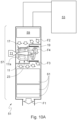
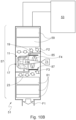
- the mixer 11 comprises, in a first variant in Fig. 10A , an open minor base 17, and, in a second variant in Fig. 10B , a closed minor base 17.
- the opposite base 19 of the mixer 11 is always open and allows exit of the exhaust gases coming from the I.C. engine 53 and radially directed against the lateral wall 23 of the mixer 11.
- the intermediate duct 57 has a substantially straight shape and defines therein a chamber 85 housing, mainly, the first unit 59, the mixer 11 and the second unit 61.
- Said intermediate duct 57 further comprises a screen 87 defining a passage for the gases exiting the mixer 11.
- the spraying nozzle 71 is arranged in front of the opening 17a of the base 17, or, more preferably, within said opening 17a, so as to entirely occupy the gap of said opening 17a, thus preventing passage of the exhaust gases and making said base 17 impermeable to the exhaust gases, and the jet emitted by the sprayer 71 is directed into the cavity 15.
- the spraying nozzle 71 is oriented so as to spray a mixture of substance in parallel flow relative to the predominant direction of advancing of the exhaust gases through the intermediate duct 57, arrows F4.
- the spraying nozzle 71 is arranged in front of the open major base 19 of the mixer 11.
- the spraying nozzle 71 is oriented so as to spray a mixture of substance in counter-flow relative to the predominant direction of advancing of the exhaust gases through the intermediate duct 57, arrows F4.
- the screen 87 provided downstream of the mixer 11 partially surrounds the mixer 11 and is arranged to convey the exhaust gases that have passed through the mixer 11 towards the second exhaust gas treatment unit 61 housed within the intermediate duct 57.
- the intermediate duct 57 has a cylindrical cross-section and the mixer 11 is housed within the duct 57 with its axis of revolution substantially perpendicular to the longitudinal axis of the duct 57 and coaxial to the screen 87.
- the sprayer 71 is preferably configured so that the mixture of substance sprayed by the nozzle 71 does not impinge against the surface of the lateral wall 23 of the mixer 11 and becomes mixed with the exhaust gas mainly outside the body of the mixer 11.
- the mixer 11 comprises a preferably closed minor base 17.
- the opposite base 19 of the mixer 11, instead, is always open and allow entrance of the exhaust gases coming from the I.C. engine and axially directed against the mixer 11 and eventually reaching the cavity 15 defined within the mixer 11.
- the intermediate duct 57 has a substantially straight shape and houses therein mainly the first unit 59, the mixer 11 and the second unit 61.
- the spraying nozzle 71 protrudes into the duct 57, downstream of the mixer 11.
- the spraying nozzle 71 is oriented so as to spray a mixture of substance in parallel flow relative to the predominant direction of advancing of the exhaust gases through the intermediate duct 57, arrows F3,F4,F5.
- the spraying nozzle 71 is provided downstream of the mixer 11 and is arranged so as to direct the mixture of substance into the duct 57, where the exhaust gases assume a whirlpool vortex-like path, arrows F4.
- the duct 57 is straight and has a cylindrical cross-section.
- the mixer 11 is arranged substantially coaxial to the duct 57 and receives the exhaust gas axially flowing through the portion of the duct 57 located upstream of the mixer 11, through the open major base 19.
- the mouths 33 and the corresponding radial openings 25 provided on the lateral wall 23 of the mixer 11 help in producing the whirlpool vortex-like motion of the exhaust gases, thus determining optimum mixing of the urea mixture introduced by the sprayer 71.
- a static mixer according to a preferred embodiment of the invention will be described, in which the body 13 of the mixer 11 is obtained by means of a metal sheet cold molding process.
- Molding preferably takes place in a sequence of successive drawing and shearing operations.
- a bell-shaped body 113 having a lateral wall 23 and comprising a closed minor base 17 and an open major base 19 is obtained, by molding, from a metal sheet.
- This first working cycle is adapted to provide the lateral surface of the body 13 with the desired shape, having a cross-section that, depending on the embodiments, may be, for example, substantially circular, hexagonal, octagonal, pentagonal.
- the body 113 has a closed lateral wall 23, which is substantially smooth and regular.
- Fig.12C shows a further intermediate step of the method according to the invention, following the cycle described above, in which the body 113 is subjected to a cutting operation, preferably a laser-cutting operation, to obtain the mouths 33.
- a cutting operation preferably a laser-cutting operation
- the body 113 is subjected to a further drawing step, in particular to prefect the shape of the body 113 of the mixer and the edges of the mouths 33.
- FIG. 12D there is illustrated a cross-section comparing the intermediate result shown in Fig.12B with the final result.
- Fig.12D the radial openings 25, over which the blades 27 and the mouths 33 extend and which are formed by the deformation of the lateral surface of the body 113, can be seen.
Landscapes
- Chemical & Material Sciences (AREA)
- Engineering & Computer Science (AREA)
- Chemical Kinetics & Catalysis (AREA)
- Combustion & Propulsion (AREA)
- Mechanical Engineering (AREA)
- General Engineering & Computer Science (AREA)
- Health & Medical Sciences (AREA)
- Toxicology (AREA)
- Dispersion Chemistry (AREA)
- Exhaust Gas After Treatment (AREA)
Description
- The invention relates to a static mixer for exhaust gas ducts of internal combustion engines, and to an exhaust unit incorporating the mixer.
- The mixer according to the invention can find application in exhaust gas ducts of internal combustion engines in which it is necessary to promote mixing of exhaust gases with a substance, or a mixture of substances, capable of chemically interacting with the exhaust gases. A particular example of application of the mixer according to the invention relates to exhaust units in which a selective catalytic reduction (SCR) of nitrogen oxides takes place.
- Static mixers are commonly used in order to promote mixing of the exhaust gases with the reducing agent, introduced in gaseous or liquid state into the exhaust systems of internal combustion engines.
- In this context, the static mixer is mainly aimed at promoting the formation of a highly homogeneous mixture and causing the reducing agent introduced into the exhaust system to be evaporated as much as possible.
- In order to meet this requirement, static mixers are at present produced, which comprise a set of blades with various orientations inside the duct in which the exhaust gases and the reducing agent mixture flow.
- The blades are generally associated with an annular frame intended to adhere to the internal walls of the duct housing the mixer, which is generally transversely arranged in the duct so that the exhaust gas flow is intercepted by said blades.
- The static mixer promotes mixing of the gases with the reducing agent, generally thanks to the increase of the turbulence phenomenon within the exhaust gas flow.
- Yet, the provision of a static mixer in the region where gases flow causes a pressure increase inside the exhaust system. Such a pressure increase is a drawback, since it is of hindrance to the discharge of the exhaust gases and, generally, it may be more or less significant, depending on the configuration of the mixer and of the exhaust system.
- Moreover, the surface of a mixer can cause condensation of the reducing mixture, with consequent formation of a liquid film, which adheres to the blades, thereby causing a reduction in the effectiveness of the mixer itself.
- Thus, two phenomena are to be countered when designing a mixer of the abovementioned kind.
- The first phenomenon is the one determined by excessive pressure increases in the exhaust system housing the mixer. The second phenomenon is the one determined by the reduction of the mixing capability, resulting from the formation of condensate of the reducing agent on the mixer surfaces.
- In an attempt to achieve the best compromise between the opposite requirements of attaining a good mixing and preventing the occurrence of the above drawbacks, different solutions have been proposed hitherto.
- Some solutions use a matrix of vanes the density, inclination and size of which are chosen by taking into account the above requirements.
US 2007/0204751 discloses an example of such kind of mixer. - Other solutions provide a set of blades, which generally are radially arranged within the duct in which the gases flow and are oriented so as to cause mixing of said gases with the reducing agent mixture. Static mixers of this second type are disclosed, for example, in
US 7,533,520 ,US 2009/0320453 ,US 2009/0266064 andUS2012/320708 . - In all the aforesaid solutions, the effort to find the best compromise between the requirements of mixing and free flowing for the exhaust gases is clearly apparent.
- Notwithstanding these efforts, the prior art mixers, however, do not wholly solve the problem of how to obtain the best mixing, while at the same time minimizing the above drawbacks.
- Moreover, the efforts made till now result in solutions that are more and more elaborate, complex and expensive to be manufactured.
-
DE 10 2017 128 672 A1 discloses a static mixer according to the preamble ofclaim 1. - In the field, therefore, there still exists a strong need to have a static mixer which is highly efficient, does not cause significant pressure increases, is scarcely prone to promote the formation of condensate and does not have the above drawbacks related to the manufacturing complexity and costs.
- Thus, it is a first object of the invention to achieve such a result, by providing a static mixer device for the treatment of exhaust gases, which enables a better mixing with respect to the prior art devices and causes a reduced pressure increase and a reduced capability to form condensate.
- A further object of the invention is to provide a static mixer of the kind discussed above, which can be industrially manufactured in simpler manner and at lower costs than prior art mixers.
- A not least object of the invention is to provide a mixer of the aforementioned type, which can be used substantially in any exhaust systems exploiting the selective catalytic reduction SCR technology.
- These and other objects are achieved by the static mixer for the treatment of exhaust gases as claimed in the appended claims, which form an integral part of the technical teaching provided herein in connection with the invention.
- The mixer according to the invention is defined by
claim 1 and essentially comprises an elongated hollow metal body, in which a pair of opposite, preferably parallel bases are defined. The body of the mixer has a frustoconical shape. - At least one of the opposite bases, preferably the largest one when said bases have surfaces with different areas, is provided with at least one axial opening. The body of the mixer further comprises a lateral wall defining a corresponding lateral surface extending between said opposite bases. The lateral wall is closed and is provided with at least one lateral opening or window.
- The static mixer for exhaust gas ducts of internal combustion engines according to the invention comprises an elongated hollow metal body having a shape, which, relative to a symmetry axis, substantially corresponds to a solid of revolution. Inside the body of the mixer, there is defined a cavity surrounded by a lateral wall connected to opposite bases, at least one of which is provided with a preferably axial opening. According to the invention, the lateral wall is closed and provided with at least one radial opening over which a concave blade is arranged. The concave blade extends radially outward of the lateral wall of the mixer body from a portion of the peripheral edge of the radial opening. The concave blade further surrounds a portion of the radial opening so as to define, in a first angular direction relative to the symmetry axis of the mixer body, a corresponding concave screen or spoon or lobe and, in a second, opposite direction, a mouth intended for the passage of gases and located substantially in front of the concave screen or spoon.
- According to the invention, the mixer body can be made of a single part, i.e. as a single piece, or can consist of several sub-parts mutually assembled to form a single element.
- In addition, according to the invention, the mixer is preferably configured and housed in an exhaust unit so that the whole gas flow in transit passes through said at least one lateral opening and said flow enters or exits through a single axial opening. For this reason, according to the invention, at least one of the opposite bases of the mixer body, preferably the minor base, is closed so as to prevent transit of gases, i.e. it is exhaust gas-tight.
- As will become more evident from the ensuing description of some preferred embodiments of the invention, the mixer according to the invention does not require any additional structures for generating the vortex-like flow in the exhaust gases passing through a treatment unit.
- The mouths and openings and corresponding blades make it possible to define substantially a baffle integrated in the mixer body, with a single front for the passage of gases, thanks to which inlet leakages are limited and flows are best directed in order to obtain an optimal vortex-like flow.
- With this feature, the mixer finds advantageous application in a plurality of arrangements with the possibility for the exhaust gas flow to flow into the device through the mouths defined by the blades and to exit in the form of a vortex-like flow from the open end, or to flow into the device in the opposite direction, entering from the open end and exiting as a vortex-like flow through the mouths.
- The performances of the mixer according to the invention are advantageously independent of, or substantially indifferent to, the angle of incidence of the exhaust gas flow onto the device. As a result, the reducing agent or mixture, for example AdBlue®, can be injected into the gas flow according to a plurality of configurations, i.e. inside or outside the mixer, upstream or downstream of the mixer, in a direction coaxial or incident to the gas flow, along the direction of the exhaust gas flow, in parallel flow, or in counter-flow.
- Advantageously, therefore, the mixer according to the invention is a substantially universal device, which does not require any substantial modifications, in exhaust gas treatment units configured even in very different manners.
- The static mixer according to the invention can advantageously be applied in exhaust gas ducts of internal combustion engines, for example Diesel cycle engines.
- Some preferred embodiments of the invention will be described below with reference to the annexed drawings, in which:
-
Fig.1 is a perspective front view of the mixer according to a preferred embodiment of the invention; -
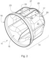
Fig.2 is a perspective rear view of the mixer inFig.1 ; -
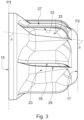
Fig.3 is a lateral plan view of the mixer inFig. 1 ; -
Fig.4 is a rear plan view of the mixer inFig.1 ; -
Fig.5 is a view corresponding toFig.1 in which a section plane is indicated; -
Fig.6 is a schematic view of the geometry of the mixer on the sectional plane inFig.5 ; -
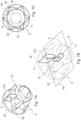
Figs. 7A and 7B are perspective views of a variant of the mixer, in which the geometric surfaces are shown; -
Fig.7C is a plan view of the mixer inFigs. 7A and 7B ; -
Fig.8 is schematic sectional view along a longitudinal plane of a preferred embodiment of the mixer associated to a spray nozzle; -
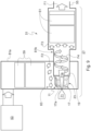
Figs. 9 to 11 are schematic views of corresponding embodiments of the exhaust gas treatment unit according to the invention; -
Figs. 12A to 12C are lateral plan views of corresponding intermediate steps of manufacturing the mixer according to the invention; -
Fig.12D is a cross-sectional view comparing the intermediate result shown inFig.12B with the final result. - The same reference numerals have been used in all the figures to identify the same or functionally equivalent components.
- Referring to
Figs. 1 to 4 , astatic mixer 11 is illustrated, intended for exhaust gas ducts of internal combustion engines and made in accordance with a preferred embodiment of the invention. Themixer 11 comprises ahollow body 13 having an elongated shape. In the illustrated embodiment, thebody 13 has a substantially frustoconical shape relative to a symmetry axis "S", i.e. thebody 13 is made substantially as a solid of revolution relative to said axis "S". Inside thebody 13, there is defined acavity 15 delimited, at its opposite ends, by a pair ofbases lateral wall 23 connected to theopposite bases - According to the invention, the
lateral wall 23 is provided with a plurality ofradial openings 25, over each of which a correspondingconcave blade 27 is arranged. Theconcave blade 27 extends radially outward of thelateral wall 23 of the body of themixer 11 from a portion of theperipheral edge 29 of theradial opening 25. In addition, eachconcave blade 27 surrounds a portion of theradial opening 25 and defines, in a first angular direction, clockwise relative to the symmetry axis inFig. 4 , a corresponding concave screen orspoon 31 and, in a second angular direction, counter-clockwise inFig. 4 , amouth 33 intended for the passage of gases and located substantially in front of the concave screen orspoon 31. In the illustrated embodiment, there is a total of sixradial openings 25, which are identical and equally spaced relative to one another, i.e. arranged angularly spaced at 60° from one another. In addition, still referring to the illustrated embodiment, theopening 25 and themouth 33 have an approximately quadrilateral shape, with the major sides arranged in an approximately axial direction, i.e. approximately parallel to the axis of revolution of thebody 13. - According to the illustrated embodiment of the invention, the
body 13 of themixer 11 comprises aminor base 17, which can be closed or open depending on the applications, and amajor base 19, preferably always open. In the shown embodiment, theminor base 17 is provided with anopening 17a for allowing entrance of the jet coming from a sprayer or nozzle spraying a mixture of a substance, usually containing urea, capable of promoting the desired chemical reaction in the exhaust gases. Preferably, said sprayer entirely occupies theopening 17a and the corresponding nozzle is oriented inward of thecavity 15, whereby said minor base is impermeable to the gases passing through themixer 11. - As can be better appreciated from
Fig. 1 , themouth 33 is delimited by aperipheral edge 35 subtending a minimum surface area, substantially incident on thelateral wall 23 of thebody 13 of themixer 11. Theedge 35 of themouth 33 further has, preferably, on thelateral wall 23, a portion in common with theedge 29 of theradial opening 25. - Referring in particular to
Figs. 3 and4 , in the illustrated embodiment, saidperipheral edge 35 lies substantially on a plane P1, incident relative to thelateral wall 23 of thebody 13 of themixer 11. In addition, still referring to the illustrated embodiment, said plane P1 is inclined by an angle δ of about 90° relative to the planes P2 and P3 on which the opposite parallel bases, 17 and 19 lie, respectively. The minimum surface subtended by theperipheral edge 35 can further have a helicoidal development, irrespective of whether it is a flat or curved surface, and can therefore be inclined relative to the axis of revolution S and to the planes P2 and P3. In the helicoidal configuration, said angle δ will therefore be other than 90° and, depending on the embodiments, may preferably be between 45° and 135°. - The plane P1 of each
mouth 33 is further preferably tangent to the same cylinder coaxial to the longitudinal axis "S" of the body of themixer 11. In the illustrated embodiment, the radius of the cylinder to which the planes P1 are tangent is approximately equal to the radius of saidopening 17a; in other embodiments, said cylinder may have radiuses different from those of theopening 17a and, furthermore, saidopening 17a may be absent. According to this embodiment of the invention, themouth 33 is oriented so as to allow passage of the gases from and towards theinner cavity 15 of themixer 11, mainly in a direction tangential to thelateral wall 23 of the mixer body, i.e. according to a direction perpendicular to the plane ofFig.3 and parallel to the plane ofFig.4 . Therefore, according to this arrangement of themouths 33, when themixer 11 is housed in an exhaust system of an internal combustion engine, the gases discharged from the engine, can, depending on the arrangement of themixer 11 in the exhaust system, either enter thecavity 15 of themixer 11 tangentially, passing at first through themouth 33 and then through theopening 25, or exit saidcavity 15 by passing at first through theopening 25 and then through themouth 33, eventually reaching the environment outside themixer 11. In both cases, the path followed by the exhaust gases between themouth 33 and theopening 25, or vice versa, will be a substantially vortex-like path, as themouth 33 and theopening 25 are oriented on planes or surfaces inclined relative to each other. - According to the embodiment shown in
Figs. 1 to 4 , themouth 33 is oriented so as to minimize the passage of the gases from and towards theinner cavity 15 of themixer 11 in an axial direction, i.e. in a direction parallel to the symmetry axis "S". - Referring to
Figs. 5 and 6 , the geometry of the mixer according to a preferred embodiment of the invention will be described in detail. -
Fig.5 shows a general sectional plane Sn, perpendicular to the axis of revolution "S", transversely cutting through thebody 13 of themixer 11 along the dashed line Rn. InFig.6 , the plane Sn intersects theedge 29 of theradial opening 25 at the points xn and xn+hn and theedge 35 of themouth 33 at the points xn and yn. The segment hn represents the transverse width on the plane Sn of theradial opening 25, defined by the angle αn between the straight line hn and the straight line tangent to the circumference at xn. In this embodiment of the invention, theradial opening 25 and themouth 33 share the portion of theirrespective edges lateral wall 23, whereby the point xn in which said edges 29 and 35 intesect the plane Sn coincides. Theradial opening 25 is extended over by theblade 27, the profile of which is defined by the angles βn and γn formed between the straight line hn and the tangent to theblade 27, respectively, at the points yn and xn + hn. On the plane Sn, theblade 27 is contained between the circumferences with radius Dxn and Dyn > Dxn, both centered on the symmetry axis S of the solid of revolution which defines thebody 13 of themixer 11. By joining the points xn and yn to a straight line Zn, having an angle θn between 0°÷90° relative to the tangent to the circumference with radius Dxn at the point xn, it is possible to obtain the plane on which the surface subtended by theedge 35 of themouth 33 extends, in the case where said mouth extends over a plane, as in the example of theFigs. 1 to 4 , or the straight lines approximating said surface at each section Sn in the case of the non-plan minimum surface area, subtended by theedge 35. - Referring to
Figs. 7A to 7C , with "A" indicating the minimum surface area subtended by theedge 35 of themouth 33, be it plan or curved, and with "a" indicating the area of the projection of said surface on a plane P4 perpendicular to the straight line Q passing through the geometric center CG of said surface and the axis of revolution "S", according to the invention the following will preferably be obtained:
- By geometric center CG of the minimum surface area subtended by the
edge 35, it is meant the "median position" of the points of the profile generated by said surface, relative to any tridimensional reference system, i.e. the arithmetic mean of the positions of each of said points along the directions x, y, z of any spatial reference system. -
Figs.7A-7C represent an embodiment of the invention in which theedge 35 of themouth 33 lies on a curved surface and, with "b" indicating the projection of the minimum surface area that is subtended by theedge 35 on a plane perpendicular to the axis of revolution "S" and does not intercept the said surface, according to the invention the following will preferably be obtained:
- In other words, assuming that the
major base 19 of thebody 13 of themixer 11 lies on a plane perpendicular to the axis of revolution "S", the projection of the minimum area surfaces subtended by theedge 35 of themouths 33 on said plane will have an area b smaller by 30% than the area A of said minimum surface area. - Advantageously, according to the invention, the
mixer 11 can be used, without substantial modifications or adaptations, in a plurality of applicative conditions. Themixer 11 can be oriented within an exhaust gas treatment unit with its axis of revolution "S" along any direction relative to the predominant direction of the gases. For example, themixer 11 can be oriented with the axis of revolution "S" perpendicular or parallel to the advancing direction of the exhaust gases. In addition, whatever the configuration adopted for the body of themixer 11 within the exhaust gas treatment unit may be, themixer 11 can be associated to a sprayer of a substance suitable for causing the desired chemical reaction, for example a reducing agent such as urea, oriented substantially according to any direction relative to the axis of revolution "S". In particular, the spraying nozzle can be oriented with its longitudinal axis parallel to the axis of revolution "S" of themixer 11, either in the same direction as the flow of exhaust gases, or in counter-flow, or the spraying nozzle can be oriented with its axis along a direction inclined relative to the axis of revolution "S". In addition, still according to the invention, themixer 11, when having different opposite bases, for example when thebody 13 is made with a frustoconical shape, can be indifferently oriented with the minor base upstream of themajor base 19, or vice versa, in the predominant direction of advancing of the exhaust gases. - Referring in particular to
Fig. 8 , there is illustrated a configuration, in which bothopposite bases body 13 of themixer 11 are open. The numeral 71 indicates a general spraying nozzle located in front of theopening 17a or, more preferably, within saidopening 17a of thebase 17, which, in the illustrate embodiment, corresponds to the minor base, thebody 13 having a frustoconical shape, so as to completely engage saidopening 17a, thus preventing the exhaust gases from entering through saidopening 17a and making saidbase 17 impermeable to the exhaust gases. Preferably, according to the invention, thenozzle 71 is arranged relative to thebody 13 in such a way that the jet of substance exiting the nozzle, typically having a frustoconical shape, indicated with thereference numeral 71a in the figure, does not impinge upon the wall of thecavity 15 within themixer 11 and is distributed in the flow of gases, immediately downstream of thesecond base 19, opposite to the base from which thejet 71a enters thebody 13 of the mixer. - Referring to
Figs. 9 to 11 , these show corresponding embodiments of an exhaustgas treatment unit 51 of aninternal combustion engine 53, in which astatic mixer 11 is incorporated, made according to the invention. Thetreatment unit 51 connects aninternal combustion engine 53, which, in the illustrated example, is a Diesel cycle engine, to anoutlet duct 55 communicating with the outer environment, arrow F1. Theunit 51 comprises at least oneintermediate duct 57 for the passage of the exhaust gases coming from theengine 53 and directed to theoutlet duct 55. Theintermediate duct 57 generally houses at least a first exhaustgas treatment unit 59, upstream of themixer 11, and at least a second exhaustgas treatment unit 61, downstream of themixer 11. - For example, the
first unit 59 arranged upstream of themixer 11 may comprise an "Oxidation Catalyst" (DOC), possibly associated with a "Diesel Particulate Filter" (DPF), and thesecond unit 61 arranged downstream of themixer 11 may comprise a "Selective Catalytic Reduction" (SCR) unit, or an SCR unit incorporated in a "soot filter" (SCRoF), possibly associated with an "Ammonia Slip Catalyst" (ASC) or a "Clean-Up Catalyst" (CUC), or a "Diesel Particulate Filter" (DPF), possibly associated with an "Ammonia Slip Catalyst" (ASC) or a "Clean-Up Catalyst" (CUC) device. - In the illustrated embodiments, a
static mixer 11 made according to the present invention and having a substantially bell-like or frustoconical shape is provided between thefirst unit 59 and thesecond unit 61. More precisely, and relative to the preferential direction of flowing of the exhaust gases through the intermediate duct 57 (arrows F2, F3), thefirst unit 59 is arranged downstream of theinternal combustion engine 53 and upstream of themixer 11, and themixer 11 is arranged upstream of thesecond unit 61. According to the described arrangement, therefore, the exhaust gases exiting theinternal combustion engine 53 flow, in order, through thefirst unit 59, themixer 11 andsecond unit 61, before passing through theoutlet duct 55 and being introduced into the atmosphere, arrow F1. - Referring now in particular to
Fig. 9 , there is illustrated a first embodiment of the exhaustgas treatment unit 51. According to this embodiment, themixer 11 comprises aminor base 17 having theaperture 17a for entrance of a flow of substance, for example urea, exiting a sprayingnozzle 71, preferably associated with a sprayer entirely occupying theopening 17a so as to prevent passage of the exhaust gases through saidopening 17a. According to the invention, theopening 17a, if any, is configured for preventing passage of the exhaust gases therethrough. Theopposite base 19 of themixer 11 is open and allows exit of the exhaust gases coming from the I.C.engine 53 and radially directed against thelateral wall 23 of themixer 11. In the shown embodiment, theintermediate duct 57 defines a substantially "L"-shaped path and includes afirst portion 81a defining achamber 83 housing thefirst unit 59 and themixer 11, and asecond portion 81b partially penetrating in thechamber 83 and surrounding thesecond base 19 of the mixer so that the entire flow of exhaust gases exiting the opening of thebase 19 is directed inside saidsecond duct portion 81b, where the exhaust gases assume a whirlpool vortex-like path, arrows F4. Preferably, bothportions portion 81b is oriented with its axis substantially perpendicular to the axis of thesection 81a. In addition, themixer 11 housed within thechamber 83 is arranged substantially coaxial to thesecond duct portion 81b and receives the exhaust gas, axially flowing through the first duct portion 81, through themouths 33 and the correspondingradial openings 25, arrows F2. - According to this embodiment, the
sprayer 71 is preferably configured so that the mixture sprayed by thenozzle 71 does not impinge against the inner surface of thelateral wall 23 of themixer 11 and becomes mixed with the exhaust gas mainly outside the body of themixer 11, inside thesecond duct portion 81b. Still according to this first embodiment described, the jet of substance sprayed by the sprayingnozzle 71 is directed in parallel flow relative to the flowing direction of the exhaust gases downstream of themixer 11, arrows F3,F4. - Referring to
Figs.10A and10B , there is illustrated a second embodiment of the exhaustgas treatment unit 51, in two embodiment variants. According to this embodiment, themixer 11 comprises, in a first variant inFig. 10A , an openminor base 17, and, in a second variant inFig. 10B , a closedminor base 17. Theopposite base 19 of themixer 11 is always open and allows exit of the exhaust gases coming from the I.C.engine 53 and radially directed against thelateral wall 23 of themixer 11. In the illustrated embodiment, theintermediate duct 57 has a substantially straight shape and defines therein achamber 85 housing, mainly, thefirst unit 59, themixer 11 and thesecond unit 61. Saidintermediate duct 57 further comprises ascreen 87 defining a passage for the gases exiting themixer 11. - According to the first embodiment variant in
Fig.10A , the sprayingnozzle 71 is arranged in front of theopening 17a of thebase 17, or, more preferably, within saidopening 17a, so as to entirely occupy the gap of saidopening 17a, thus preventing passage of the exhaust gases and making saidbase 17 impermeable to the exhaust gases, and the jet emitted by thesprayer 71 is directed into thecavity 15. In this first embodiment variant, the sprayingnozzle 71 is oriented so as to spray a mixture of substance in parallel flow relative to the predominant direction of advancing of the exhaust gases through theintermediate duct 57, arrows F4. - According to the second embodiment variant in
Fig.10B , the sprayingnozzle 71 is arranged in front of the openmajor base 19 of themixer 11. In this second embodiment variant, the sprayingnozzle 71 is oriented so as to spray a mixture of substance in counter-flow relative to the predominant direction of advancing of the exhaust gases through theintermediate duct 57, arrows F4. - The
screen 87 provided downstream of themixer 11 partially surrounds themixer 11 and is arranged to convey the exhaust gases that have passed through themixer 11 towards the second exhaustgas treatment unit 61 housed within theintermediate duct 57. - In addition, similarly to the first embodiment, the exhaust gases coming from the
engine 53 radially impinge against thelateral wall 23 of themixer 11 and penetrate into thecavity 15 provided within themixer 11 through themouths 33 and the correspondingradial 25, arrows F2. - Preferably, the
intermediate duct 57 has a cylindrical cross-section and themixer 11 is housed within theduct 57 with its axis of revolution substantially perpendicular to the longitudinal axis of theduct 57 and coaxial to thescreen 87. - According to this embodiment, the
sprayer 71 is preferably configured so that the mixture of substance sprayed by thenozzle 71 does not impinge against the surface of thelateral wall 23 of themixer 11 and becomes mixed with the exhaust gas mainly outside the body of themixer 11. - Referring now to
Fig. 11 , there is illustrated a third embodiment of the exhaustgas treatment unit 51. According to this embodiment, themixer 11 comprises a preferably closedminor base 17. Theopposite base 19 of themixer 11, instead, is always open and allow entrance of the exhaust gases coming from the I.C. engine and axially directed against themixer 11 and eventually reaching thecavity 15 defined within themixer 11. In the illustrated embodiment, theintermediate duct 57 has a substantially straight shape and houses therein mainly thefirst unit 59, themixer 11 and thesecond unit 61. In addition, the sprayingnozzle 71 protrudes into theduct 57, downstream of themixer 11. - In this embodiment, the spraying
nozzle 71 is oriented so as to spray a mixture of substance in parallel flow relative to the predominant direction of advancing of the exhaust gases through theintermediate duct 57, arrows F3,F4,F5. In addition, the sprayingnozzle 71 is provided downstream of themixer 11 and is arranged so as to direct the mixture of substance into theduct 57, where the exhaust gases assume a whirlpool vortex-like path, arrows F4. - Preferably, the
duct 57 is straight and has a cylindrical cross-section. In addition, themixer 11 is arranged substantially coaxial to theduct 57 and receives the exhaust gas axially flowing through the portion of theduct 57 located upstream of themixer 11, through the openmajor base 19. - According to this embodiment of the invention, the
mouths 33 and the correspondingradial openings 25 provided on thelateral wall 23 of themixer 11 help in producing the whirlpool vortex-like motion of the exhaust gases, thus determining optimum mixing of the urea mixture introduced by thesprayer 71. - Referring to
Figs. 12A to 12D , the method of making a static mixer according to a preferred embodiment of the invention will be described, in which thebody 13 of themixer 11 is obtained by means of a metal sheet cold molding process. - Molding preferably takes place in a sequence of successive drawing and shearing operations.
- Referring to
Figs. 12A and 12B , there is illustrated an intermediate sequence of steps of the method according to this preferred embodiment of the invention, in which a bell-shapedbody 113 having alateral wall 23 and comprising a closedminor base 17 and an openmajor base 19 is obtained, by molding, from a metal sheet. This first working cycle is adapted to provide the lateral surface of thebody 13 with the desired shape, having a cross-section that, depending on the embodiments, may be, for example, substantially circular, hexagonal, octagonal, pentagonal. At the end of this first working cycle, thebody 113 has a closedlateral wall 23, which is substantially smooth and regular. -
Fig.12C shows a further intermediate step of the method according to the invention, following the cycle described above, in which thebody 113 is subjected to a cutting operation, preferably a laser-cutting operation, to obtain themouths 33. - At the end of the cycle described above, the
body 113 is subjected to a further drawing step, in particular to prefect the shape of thebody 113 of the mixer and the edges of themouths 33. - Referring to
Fig. 12D , there is illustrated a cross-section comparing the intermediate result shown inFig.12B with the final result. InFig.12D theradial openings 25, over which theblades 27 and themouths 33 extend and which are formed by the deformation of the lateral surface of thebody 113, can be seen.
Claims (12)
- Static mixer (11) for exhaust gas ducts of internal combustion engines, comprising an elongated hollow metal body (13) having a shape which, relative to a symmetry axis (S), substantially corresponds to a solid of revolution defining at its inside a cavity (15), in which opposite bases (17,19) are defined, at least one of which is provided with an axial opening, and a closed lateral wall (23) is defined connected to the opposite bases (17,19) and having at least one radial opening (25) over which a concave blade (27) is arranged extending radially outward of the lateral wall (23) of the mixer body from a portion of the peripheral edge (29) of the radial opening (25) and surrounding a portion of the radial opening (25) so as to define, in a first angular direction relative to the symmetry axis, a corresponding concave screen (31) and, in a second, opposite direction, a mouth (33) intended for the passage of gases and located substantially in front of the concave screen (31), wherein the body (13) of the mixer (11) has a frustoconical shape, characterized in that one of the basis of the body (13) of the mixer (11) is closed and thus exhaust-gas tight.
- Mixer according to claim 1, wherein the mouth (33) for the passage of gases is delimited by a peripheral edge (35) subtending a minimum surface area substantially incident on the lateral wall (23) of the mixer body.
- Mixer according to claim 1 or 2, wherein the mouth (33) for the passage of gases is oriented so as to allow the passage of gases from and towards the inner cavity (15) of the mixer (11), mainly in a tangential direction relative to the lateral wall (23) of the mixer body.
- Mixer according to claim 1 or 2 or 3, wherein the mouth (33) for the passage of gases is oriented so as to minimize the passage of gases from and towards the inner cavity (15) of the mixer (11) in an axial direction relative to the lateral wall (23) of the mixer body.
- Mixer according to any of the preceding claims, wherein between the radial opening (25) and the mouth (33), and vice versa, a substantially vortex-like path for the gases is established, by virtue of the concave blade (27), in a plane perpendicular to the symmetry axis (S) of the mixer body.
- Mixer according to any of the preceding claims, wherein a straight line (Zn) passing through the proximal (xn) and distal (yn) points of intersection relative to the symmetry axis (S), between a section plane (Sn) perpendicular to the symmetry axis and the proximal edge (29) of the radial opening (25) and the distal edge (35) of the mouth (33), respectively, forms, with the tangent to the lateral wall (23) in the proximal point of intersection (xn), an angle (θn) comprised between 0 and 90°.
- Mixer according to claim 6, wherein the mouth (33) extends radially, for each section plane (Sn) perpendicular to the symmetry axis, between a first circumference (Dxn) on said plane passing through the proximal point of intersection (xn) and having its center in the symmetry axis, and a second circumference (Dyn) on said plane, passing through the distal point (yn) and having its center in the symmetry axis.
- Mixer according to claim 7, wherein the ratio between the area "a" of the projection of the minimum surface area subtended by the edge (35) of the mouth (33) on a plane perpendicular to a straight line (Q) passing through the geometrical center of said minimum surface and the symmetry axis (S) and the area "A" of the minimum surface area meets the following equation:

- Mixer according to claim 7 or 8, wherein the ratio between the area "b" of the projection of the minimum surface area subtended by the edge (35) of the mouth (33) on a plane which is perpendicular to the symmetry axis (S) and does not intersect said surface, and the area "A" of said minimum surface area meets the following equation:

- Mixer according to any of the preceding claims, wherein said solid of revolution comprises a cone or a cylinder ad wherein the opposite bases (17,19) are circular and extend over respective parallel planes perpendicular to the symmetry axis (S), the lateral wall (23) of said cone or cylinder being provided with a plurality of said radial openings (25), corresponding concave blades (27) and mouths (33) for the passage of gases.
- Mixer according to claim 1, wherein said closed base (17) corresponds to the minor base of the frustoconical body (13) of the mixer (11).
- An exhaust gas treatment unit (51) of an internal combustion engine, said exhaust gas treatment unit comprising an intermediate duct (57), connecting an internal combustion engine (53) to an outlet duct (55), a static mixer (11) according to claim 1, housed within said intermediate duct (57), at least a first exhaust gas treatment unit (59) housed within said intermediate duct (57) upstream of the static mixer (11), and at least a second exhaust gas treatment unit (61) housed within said intermediate duct (57) downstream of the static mixer (11), wherein all the exhaust gases exiting the internal combustion engine (53) flow, in order, through the first exhaust gas treatment unit (59), the static mixer (11) and the second exhaust gas treatment unit (61) before passing through the outlet duct (55) and being introduced in the atmosphere.
Applications Claiming Priority (2)
| Application Number | Priority Date | Filing Date | Title |
|---|---|---|---|
| IT102018000007427A IT201800007427A1 (en) | 2018-07-23 | 2018-07-23 | Static mixer for exhaust gas ducts of endothermic engines, its method of construction and exhaust group that incorporates the mixer. |
| PCT/IB2019/056269 WO2020021444A1 (en) | 2018-07-23 | 2019-07-23 | Static mixer for exhaust gas ducts of internal combustion engines, method of manufacturing thereof and exhaust unit incorporating the mixer |
Publications (3)
| Publication Number | Publication Date |
|---|---|
| EP3826756A1 EP3826756A1 (en) | 2021-06-02 |
| EP3826756C0 EP3826756C0 (en) | 2024-09-04 |
| EP3826756B1 true EP3826756B1 (en) | 2024-09-04 |
Family
ID=63834575
Family Applications (1)
| Application Number | Title | Priority Date | Filing Date |
|---|---|---|---|
| EP19759050.8A Active EP3826756B1 (en) | 2018-07-23 | 2019-07-23 | Static mixer for exhaust gas ducts of internal combustion engines and exhaust unit incorporating the mixer |
Country Status (6)
| Country | Link |
|---|---|
| US (1) | US11560820B2 (en) |
| EP (1) | EP3826756B1 (en) |
| CN (2) | CN112512674A (en) |
| IT (1) | IT201800007427A1 (en) |
| MX (1) | MX2021000956A (en) |
| WO (1) | WO2020021444A1 (en) |
Families Citing this family (8)
| Publication number | Priority date | Publication date | Assignee | Title |
|---|---|---|---|---|
| WO2020009694A1 (en) | 2018-07-03 | 2020-01-09 | Cummins Emission Solutions Inc. | Body mixing decomposition reactor |
| IT201800007854A1 (en) * | 2018-08-03 | 2020-02-03 | Officine Metallurgiche G Cornaglia Spa | Panel air filter cartridge for endothermic engines |
| USD959514S1 (en) * | 2020-07-17 | 2022-08-02 | Commonwealth Scientific And Industrial Research Organisation | Static mixer |
| USD959517S1 (en) * | 2020-07-23 | 2022-08-02 | Commonwealth Scientific And Industrial Research Organisation | Static mixer |
| USD959518S1 (en) * | 2020-07-23 | 2022-08-02 | Commonwealth Scientific And Industrial Research Organisation | Static mixer |
| DE102020128226B3 (en) * | 2020-10-27 | 2021-09-02 | Tenneco Gmbh | Mixing tube |
| US12228061B2 (en) | 2021-06-30 | 2025-02-18 | Cummins Emission Solutions Inc. | Decomposition chamber with guide swirl mixer |
| CN119604670A (en) * | 2022-08-09 | 2025-03-11 | 康明斯排放处理公司 | Mixer for exhaust aftertreatment system |
Family Cites Families (16)
| Publication number | Priority date | Publication date | Assignee | Title |
|---|---|---|---|---|
| FR1152871A (en) * | 1955-08-20 | 1958-02-26 | Gama Soc | Exhaust silencer improvements |
| DE102006024778B3 (en) | 2006-03-02 | 2007-07-19 | J. Eberspächer GmbH & Co. KG | Static mixer for exhaust system of internal combustion engine, has flow conducting surfaces arranged at web materials so that surfaces are arranged with cells at their diverting side and extend in direction of flow in tube |
| US7533520B2 (en) | 2006-04-24 | 2009-05-19 | Fleetguard, Inc. | Exhaust aftertreatment mixer with stamped muffler flange |
| US8141353B2 (en) | 2008-04-25 | 2012-03-27 | Tenneco Automotive Operating Company Inc. | Exhaust gas additive/treatment system and mixer for use therein |
| US8397495B2 (en) | 2008-06-26 | 2013-03-19 | Tenneco Automotive Operating Company Inc. | Exhaust gas additive/treatment system and mixer for use therein |
| DE102010056314A1 (en) * | 2010-12-27 | 2012-06-28 | Friedrich Boysen Gmbh & Co. Kg | Device for distributing fluids in exhaust systems |
| DE102011077645A1 (en) | 2011-06-16 | 2012-12-20 | Bosch Emission Systems Gmbh & Co. Kg | Static mixer |
| ITTO20110535A1 (en) * | 2011-06-20 | 2012-12-21 | Cornaglia G Off Met Spa | STATIC MIXER FOR THE TREATMENT OF EXHAUST GAS AND ITS MANUFACTURING METHOD. |
| EP2607641A1 (en) * | 2011-12-19 | 2013-06-26 | Mtu Friedrichshafen Gmbh | Mixer device for introducing a reducing agent to an exhaust gas flow with blade-shaped means |
| US9410464B2 (en) * | 2013-08-06 | 2016-08-09 | Tenneco Automotive Operating Company Inc. | Perforated mixing pipe with swirler |
| WO2015076765A1 (en) * | 2013-11-22 | 2015-05-28 | Ford Otomotiv Sanayi Anonim Sirketi | A mixer |
| EP3099906B1 (en) * | 2014-01-31 | 2018-10-10 | Donaldson Company, Inc. | Dosing and mixing arrangement for use in exhaust aftertreatment |
| WO2015164356A1 (en) * | 2014-04-24 | 2015-10-29 | Tenneco Automotive Operating Company Inc. | Perforated mixing pipe with swirler |
| GB2539711B (en) * | 2015-06-26 | 2017-08-16 | Proventia Emission Control Oy | Method and apparatus for evenly mixing reactant to exhaust gas flow |
| US10273853B2 (en) * | 2017-09-29 | 2019-04-30 | Tenneco Automotive Operating Company Inc. | Wire mesh mixing tube |
| DE102017128672A1 (en) * | 2017-12-04 | 2018-02-22 | FEV Europe GmbH | Shield for a urea injection device |
-
2018
- 2018-07-23 IT IT102018000007427A patent/IT201800007427A1/en unknown
-
2019
- 2019-07-23 MX MX2021000956A patent/MX2021000956A/en unknown
- 2019-07-23 US US17/262,247 patent/US11560820B2/en active Active
- 2019-07-23 EP EP19759050.8A patent/EP3826756B1/en active Active
- 2019-07-23 CN CN201980049037.4A patent/CN112512674A/en active Pending
- 2019-07-23 CN CN202510680698.4A patent/CN120550665A/en active Pending
- 2019-07-23 WO PCT/IB2019/056269 patent/WO2020021444A1/en not_active Ceased
Also Published As
| Publication number | Publication date |
|---|---|
| EP3826756C0 (en) | 2024-09-04 |
| IT201800007427A1 (en) | 2020-01-23 |
| US11560820B2 (en) | 2023-01-24 |
| BR112021001230A2 (en) | 2021-04-27 |
| US20210348538A1 (en) | 2021-11-11 |
| MX2021000956A (en) | 2021-06-23 |
| EP3826756A1 (en) | 2021-06-02 |
| WO2020021444A1 (en) | 2020-01-30 |
| CN112512674A (en) | 2021-03-16 |
| CN120550665A (en) | 2025-08-29 |
Similar Documents
| Publication | Publication Date | Title |
|---|---|---|
| US11560820B2 (en) | Static mixer for exhaust gas ducts of internal combustion engines, method of manufacturing thereof and exhaust unit incorporating the mixer | |
| US10273855B2 (en) | Exhaust aftertreatment system having mixer assembly | |
| US11193412B2 (en) | Automotive exhaust aftertreatment system | |
| US9828897B2 (en) | Mixer for a vehicle exhaust system | |
| US20180306083A1 (en) | Counter-swirl mixer | |
| US20260071567A1 (en) | Reductant delivery system for exhaust gas aftertreatment system | |
| US8956040B2 (en) | Static mixer for the treatment of exhaust gases and manufacturing method thereof | |
| EP2512642B1 (en) | Mixing system for an exhaust gases after-treatment arrangement | |
| EP3760846A1 (en) | System for mixing a liquid spray into a gaseous flow and exhaust aftertreatment device comprising same | |
| US20230151755A1 (en) | Decomposition chamber | |
| CN107435576B (en) | Integrated exhaust aftertreatment system | |
| US11725563B2 (en) | Mixer, exhaust aftertreatment component, exhaust aftertreatment system and vehicle | |
| CN212054866U (en) | Tail gas aftertreatment system | |
| WO2016146015A1 (en) | Mixing tube and exhaust gas treatment device thereof | |
| CN111828140B (en) | Mixing device | |
| CN104131869B (en) | Flow-in chamber used for catalytic converter of discharge control system | |
| KR101599838B1 (en) | Mixing apparatus for an exhaust after-treatment system of a vehicle | |
| US20170362987A1 (en) | Engine system having mixing mechanism for exhaust and injected fluid and engine exhaust treatment strategy | |
| KR101898235B1 (en) | Mixing apparatus for selective catalytic reduction-catalysator | |
| JP7759199B2 (en) | Exhaust gas treatment device for an exhaust system of an internal combustion engine | |
| KR20200098197A (en) | Mixer for exhaust system | |
| BR112021001230B1 (en) | STATIC MIXER FOR EXHAUST GAS DUCTS OF INTERNAL COMBUSTION ENGINES | |
| JP7556829B2 (en) | Exhaust Gas Purification Device | |
| CN113530648B (en) | Exhaust gas aftertreatment system | |
| CN115523014A (en) | Mixer assembly |
Legal Events
| Date | Code | Title | Description |
|---|---|---|---|
| STAA | Information on the status of an ep patent application or granted ep patent |
Free format text: STATUS: UNKNOWN |
|
| STAA | Information on the status of an ep patent application or granted ep patent |
Free format text: STATUS: THE INTERNATIONAL PUBLICATION HAS BEEN MADE |
|
| PUAI | Public reference made under article 153(3) epc to a published international application that has entered the european phase |
Free format text: ORIGINAL CODE: 0009012 |
|
| STAA | Information on the status of an ep patent application or granted ep patent |
Free format text: STATUS: REQUEST FOR EXAMINATION WAS MADE |
|
| 17P | Request for examination filed |
Effective date: 20210201 |
|
| AK | Designated contracting states |
Kind code of ref document: A1 Designated state(s): AL AT BE BG CH CY CZ DE DK EE ES FI FR GB GR HR HU IE IS IT LI LT LU LV MC MK MT NL NO PL PT RO RS SE SI SK SM TR |
|
| DAV | Request for validation of the european patent (deleted) | ||
| DAX | Request for extension of the european patent (deleted) | ||
| STAA | Information on the status of an ep patent application or granted ep patent |
Free format text: STATUS: EXAMINATION IS IN PROGRESS |
|
| 17Q | First examination report despatched |
Effective date: 20221104 |
|
| REG | Reference to a national code |
Ref country code: DE Ref legal event code: R079 Free format text: PREVIOUS MAIN CLASS: B01F0003040000 Ipc: B01F0023213000 Ref country code: DE Ref legal event code: R079 Ref document number: 602019058321 Country of ref document: DE Free format text: PREVIOUS MAIN CLASS: B01F0003040000 Ipc: B01F0023213000 |
|
| GRAP | Despatch of communication of intention to grant a patent |
Free format text: ORIGINAL CODE: EPIDOSNIGR1 |
|
| STAA | Information on the status of an ep patent application or granted ep patent |
Free format text: STATUS: GRANT OF PATENT IS INTENDED |
|
| RIC1 | Information provided on ipc code assigned before grant |
Ipc: B01F 25/00 20220101ALN20240307BHEP Ipc: F01N 3/28 20060101ALI20240307BHEP Ipc: F01N 3/20 20060101ALI20240307BHEP Ipc: B01F 25/431 20220101ALI20240307BHEP Ipc: B01F 25/314 20220101ALI20240307BHEP Ipc: B01F 23/213 20220101AFI20240307BHEP |
|
| INTG | Intention to grant announced |
Effective date: 20240404 |
|
| GRAS | Grant fee paid |
Free format text: ORIGINAL CODE: EPIDOSNIGR3 |
|
| GRAA | (expected) grant |
Free format text: ORIGINAL CODE: 0009210 |
|
| STAA | Information on the status of an ep patent application or granted ep patent |
Free format text: STATUS: THE PATENT HAS BEEN GRANTED |
|
| AK | Designated contracting states |
Kind code of ref document: B1 Designated state(s): AL AT BE BG CH CY CZ DE DK EE ES FI FR GB GR HR HU IE IS IT LI LT LU LV MC MK MT NL NO PL PT RO RS SE SI SK SM TR |
|
| REG | Reference to a national code |
Ref country code: GB Ref legal event code: FG4D |
|
| REG | Reference to a national code |
Ref country code: CH Ref legal event code: EP |
|
| REG | Reference to a national code |
Ref country code: IE Ref legal event code: FG4D |
|
| REG | Reference to a national code |
Ref country code: DE Ref legal event code: R096 Ref document number: 602019058321 Country of ref document: DE |
|
| U01 | Request for unitary effect filed |
Effective date: 20241001 |
|
| U07 | Unitary effect registered |
Designated state(s): AT BE BG DE DK EE FI FR IT LT LU LV MT NL PT RO SE SI Effective date: 20241030 |
|
| PG25 | Lapsed in a contracting state [announced via postgrant information from national office to epo] |
Ref country code: NO Free format text: LAPSE BECAUSE OF FAILURE TO SUBMIT A TRANSLATION OF THE DESCRIPTION OR TO PAY THE FEE WITHIN THE PRESCRIBED TIME-LIMIT Effective date: 20241204 |
|
| PG25 | Lapsed in a contracting state [announced via postgrant information from national office to epo] |
Ref country code: GR Free format text: LAPSE BECAUSE OF FAILURE TO SUBMIT A TRANSLATION OF THE DESCRIPTION OR TO PAY THE FEE WITHIN THE PRESCRIBED TIME-LIMIT Effective date: 20241205 Ref country code: PL Free format text: LAPSE BECAUSE OF FAILURE TO SUBMIT A TRANSLATION OF THE DESCRIPTION OR TO PAY THE FEE WITHIN THE PRESCRIBED TIME-LIMIT Effective date: 20240904 |
|
| PG25 | Lapsed in a contracting state [announced via postgrant information from national office to epo] |
Ref country code: HR Free format text: LAPSE BECAUSE OF FAILURE TO SUBMIT A TRANSLATION OF THE DESCRIPTION OR TO PAY THE FEE WITHIN THE PRESCRIBED TIME-LIMIT Effective date: 20240904 |
|
| PG25 | Lapsed in a contracting state [announced via postgrant information from national office to epo] |
Ref country code: ES Free format text: LAPSE BECAUSE OF FAILURE TO SUBMIT A TRANSLATION OF THE DESCRIPTION OR TO PAY THE FEE WITHIN THE PRESCRIBED TIME-LIMIT Effective date: 20240904 Ref country code: RS Free format text: LAPSE BECAUSE OF FAILURE TO SUBMIT A TRANSLATION OF THE DESCRIPTION OR TO PAY THE FEE WITHIN THE PRESCRIBED TIME-LIMIT Effective date: 20241204 |
|
| PG25 | Lapsed in a contracting state [announced via postgrant information from national office to epo] |
Ref country code: RS Free format text: LAPSE BECAUSE OF FAILURE TO SUBMIT A TRANSLATION OF THE DESCRIPTION OR TO PAY THE FEE WITHIN THE PRESCRIBED TIME-LIMIT Effective date: 20241204 Ref country code: PL Free format text: LAPSE BECAUSE OF FAILURE TO SUBMIT A TRANSLATION OF THE DESCRIPTION OR TO PAY THE FEE WITHIN THE PRESCRIBED TIME-LIMIT Effective date: 20240904 Ref country code: NO Free format text: LAPSE BECAUSE OF FAILURE TO SUBMIT A TRANSLATION OF THE DESCRIPTION OR TO PAY THE FEE WITHIN THE PRESCRIBED TIME-LIMIT Effective date: 20241204 Ref country code: HR Free format text: LAPSE BECAUSE OF FAILURE TO SUBMIT A TRANSLATION OF THE DESCRIPTION OR TO PAY THE FEE WITHIN THE PRESCRIBED TIME-LIMIT Effective date: 20240904 Ref country code: GR Free format text: LAPSE BECAUSE OF FAILURE TO SUBMIT A TRANSLATION OF THE DESCRIPTION OR TO PAY THE FEE WITHIN THE PRESCRIBED TIME-LIMIT Effective date: 20241205 Ref country code: ES Free format text: LAPSE BECAUSE OF FAILURE TO SUBMIT A TRANSLATION OF THE DESCRIPTION OR TO PAY THE FEE WITHIN THE PRESCRIBED TIME-LIMIT Effective date: 20240904 |
|
| PG25 | Lapsed in a contracting state [announced via postgrant information from national office to epo] |
Ref country code: IS Free format text: LAPSE BECAUSE OF FAILURE TO SUBMIT A TRANSLATION OF THE DESCRIPTION OR TO PAY THE FEE WITHIN THE PRESCRIBED TIME-LIMIT Effective date: 20250104 |
|
| PG25 | Lapsed in a contracting state [announced via postgrant information from national office to epo] |
Ref country code: SM Free format text: LAPSE BECAUSE OF FAILURE TO SUBMIT A TRANSLATION OF THE DESCRIPTION OR TO PAY THE FEE WITHIN THE PRESCRIBED TIME-LIMIT Effective date: 20240904 |
|
| PG25 | Lapsed in a contracting state [announced via postgrant information from national office to epo] |
Ref country code: CZ Free format text: LAPSE BECAUSE OF FAILURE TO SUBMIT A TRANSLATION OF THE DESCRIPTION OR TO PAY THE FEE WITHIN THE PRESCRIBED TIME-LIMIT Effective date: 20240904 |
|
| PG25 | Lapsed in a contracting state [announced via postgrant information from national office to epo] |
Ref country code: SK Free format text: LAPSE BECAUSE OF FAILURE TO SUBMIT A TRANSLATION OF THE DESCRIPTION OR TO PAY THE FEE WITHIN THE PRESCRIBED TIME-LIMIT Effective date: 20240904 |
|
| PLBE | No opposition filed within time limit |
Free format text: ORIGINAL CODE: 0009261 |
|
| STAA | Information on the status of an ep patent application or granted ep patent |
Free format text: STATUS: NO OPPOSITION FILED WITHIN TIME LIMIT |
|
| 26N | No opposition filed |
Effective date: 20250605 |
|
| U20 | Renewal fee for the european patent with unitary effect paid |
Year of fee payment: 7 Effective date: 20250724 |
|
| REG | Reference to a national code |
Ref country code: CH Ref legal event code: H13 Free format text: ST27 STATUS EVENT CODE: U-0-0-H10-H13 (AS PROVIDED BY THE NATIONAL OFFICE) Effective date: 20260224 |
|
| GBPC | Gb: european patent ceased through non-payment of renewal fee |
Effective date: 20250723 |
|
| PG25 | Lapsed in a contracting state [announced via postgrant information from national office to epo] |
Ref country code: GB Free format text: LAPSE BECAUSE OF NON-PAYMENT OF DUE FEES Effective date: 20250723 |
|
| PG25 | Lapsed in a contracting state [announced via postgrant information from national office to epo] |
Ref country code: CH Free format text: LAPSE BECAUSE OF NON-PAYMENT OF DUE FEES Effective date: 20250731 |