EP3826424A1 - Control device, program, control method, and flying object - Google Patents
Control device, program, control method, and flying object Download PDFInfo
- Publication number
- EP3826424A1 EP3826424A1 EP19851929.0A EP19851929A EP3826424A1 EP 3826424 A1 EP3826424 A1 EP 3826424A1 EP 19851929 A EP19851929 A EP 19851929A EP 3826424 A1 EP3826424 A1 EP 3826424A1
- Authority
- EP
- European Patent Office
- Prior art keywords
- flight
- flight vehicle
- area
- target area
- vehicle
- Prior art date
- Legal status (The legal status is an assumption and is not a legal conclusion. Google has not performed a legal analysis and makes no representation as to the accuracy of the status listed.)
- Granted
Links
Images







Classifications
-
- G—PHYSICS
- G08—SIGNALLING
- G08G—TRAFFIC CONTROL SYSTEMS
- G08G5/00—Traffic control systems for aircraft
- G08G5/20—Arrangements for acquiring, generating, sharing or displaying traffic information
- G08G5/25—Transmission of traffic-related information between aircraft
-
- B—PERFORMING OPERATIONS; TRANSPORTING
- B64—AIRCRAFT; AVIATION; COSMONAUTICS
- B64C—AEROPLANES; HELICOPTERS
- B64C13/00—Control systems or transmitting systems for actuating flying-control surfaces, lift-increasing flaps, air brakes, or spoilers
- B64C13/02—Initiating means
- B64C13/16—Initiating means actuated automatically, e.g. responsive to gust detectors
- B64C13/18—Initiating means actuated automatically, e.g. responsive to gust detectors using automatic pilot
-
- B—PERFORMING OPERATIONS; TRANSPORTING
- B64—AIRCRAFT; AVIATION; COSMONAUTICS
- B64C—AEROPLANES; HELICOPTERS
- B64C39/00—Aircraft not otherwise provided for
- B64C39/10—All-wing aircraft
-
- B—PERFORMING OPERATIONS; TRANSPORTING
- B64—AIRCRAFT; AVIATION; COSMONAUTICS
- B64U—UNMANNED AERIAL VEHICLES [UAV]; EQUIPMENT THEREFOR
- B64U50/00—Propulsion; Power supply
- B64U50/10—Propulsion
- B64U50/13—Propulsion using external fans or propellers
-
- B—PERFORMING OPERATIONS; TRANSPORTING
- B64—AIRCRAFT; AVIATION; COSMONAUTICS
- B64U—UNMANNED AERIAL VEHICLES [UAV]; EQUIPMENT THEREFOR
- B64U50/00—Propulsion; Power supply
- B64U50/10—Propulsion
- B64U50/19—Propulsion using electrically powered motors
-
- B—PERFORMING OPERATIONS; TRANSPORTING
- B64—AIRCRAFT; AVIATION; COSMONAUTICS
- B64U—UNMANNED AERIAL VEHICLES [UAV]; EQUIPMENT THEREFOR
- B64U50/00—Propulsion; Power supply
- B64U50/30—Supply or distribution of electrical power
- B64U50/31—Supply or distribution of electrical power generated by photovoltaics
-
- G—PHYSICS
- G05—CONTROLLING; REGULATING
- G05D—SYSTEMS FOR CONTROLLING OR REGULATING NON-ELECTRIC VARIABLES
- G05D1/00—Control of position, course, altitude or attitude of land, water, air or space vehicles, e.g. using automatic pilots
- G05D1/04—Control of altitude or depth
- G05D1/06—Rate of change of altitude or depth
- G05D1/0607—Rate of change of altitude or depth specially adapted for aircraft
-
- G—PHYSICS
- G05—CONTROLLING; REGULATING
- G05D—SYSTEMS FOR CONTROLLING OR REGULATING NON-ELECTRIC VARIABLES
- G05D1/00—Control of position, course, altitude or attitude of land, water, air or space vehicles, e.g. using automatic pilots
- G05D1/10—Simultaneous control of position or course in three dimensions
- G05D1/101—Simultaneous control of position or course in three dimensions specially adapted for aircraft
- G05D1/104—Simultaneous control of position or course in three dimensions specially adapted for aircraft involving a plurality of aircrafts, e.g. formation flying
-
- G—PHYSICS
- G05—CONTROLLING; REGULATING
- G05D—SYSTEMS FOR CONTROLLING OR REGULATING NON-ELECTRIC VARIABLES
- G05D1/00—Control of position, course, altitude or attitude of land, water, air or space vehicles, e.g. using automatic pilots
- G05D1/10—Simultaneous control of position or course in three dimensions
- G05D1/101—Simultaneous control of position or course in three dimensions specially adapted for aircraft
- G05D1/105—Simultaneous control of position or course in three dimensions specially adapted for aircraft specially adapted for unpowered flight, e.g. glider, parachuting, forced landing
-
- G—PHYSICS
- G08—SIGNALLING
- G08G—TRAFFIC CONTROL SYSTEMS
- G08G5/00—Traffic control systems for aircraft
-
- G—PHYSICS
- G08—SIGNALLING
- G08G—TRAFFIC CONTROL SYSTEMS
- G08G5/00—Traffic control systems for aircraft
- G08G5/20—Arrangements for acquiring, generating, sharing or displaying traffic information
- G08G5/21—Arrangements for acquiring, generating, sharing or displaying traffic information located onboard the aircraft
-
- G—PHYSICS
- G08—SIGNALLING
- G08G—TRAFFIC CONTROL SYSTEMS
- G08G5/00—Traffic control systems for aircraft
- G08G5/20—Arrangements for acquiring, generating, sharing or displaying traffic information
- G08G5/26—Transmission of traffic-related information between aircraft and ground stations
-
- G—PHYSICS
- G08—SIGNALLING
- G08G—TRAFFIC CONTROL SYSTEMS
- G08G5/00—Traffic control systems for aircraft
- G08G5/50—Navigation or guidance aids
- G08G5/55—Navigation or guidance aids for a single aircraft
-
- G—PHYSICS
- G08—SIGNALLING
- G08G—TRAFFIC CONTROL SYSTEMS
- G08G5/00—Traffic control systems for aircraft
- G08G5/50—Navigation or guidance aids
- G08G5/56—Navigation or guidance aids for two or more aircraft
-
- G—PHYSICS
- G08—SIGNALLING
- G08G—TRAFFIC CONTROL SYSTEMS
- G08G5/00—Traffic control systems for aircraft
- G08G5/70—Arrangements for monitoring traffic-related situations or conditions
- G08G5/76—Arrangements for monitoring traffic-related situations or conditions for monitoring atmospheric conditions
-
- H—ELECTRICITY
- H01—ELECTRIC ELEMENTS
- H01Q—ANTENNAS, i.e. RADIO AERIALS
- H01Q1/00—Details of, or arrangements associated with, antennas
- H01Q1/27—Adaptation for use in or on movable bodies
- H01Q1/28—Adaptation for use in or on aircraft, missiles, satellites, or balloons
-
- H—ELECTRICITY
- H04—ELECTRIC COMMUNICATION TECHNIQUE
- H04B—TRANSMISSION
- H04B7/00—Radio transmission systems, i.e. using radiation field
- H04B7/14—Relay systems
- H04B7/15—Active relay systems
- H04B7/185—Space-based or airborne stations; Stations for satellite systems
-
- H—ELECTRICITY
- H04—ELECTRIC COMMUNICATION TECHNIQUE
- H04W—WIRELESS COMMUNICATION NETWORKS
- H04W16/00—Network planning, e.g. coverage or traffic planning tools; Network deployment, e.g. resource partitioning or cells structures
- H04W16/24—Cell structures
-
- H—ELECTRICITY
- H04—ELECTRIC COMMUNICATION TECHNIQUE
- H04W—WIRELESS COMMUNICATION NETWORKS
- H04W4/00—Services specially adapted for wireless communication networks; Facilities therefor
- H04W4/30—Services specially adapted for particular environments, situations or purposes
- H04W4/40—Services specially adapted for particular environments, situations or purposes for vehicles, e.g. vehicle-to-pedestrians [V2P]
- H04W4/42—Services specially adapted for particular environments, situations or purposes for vehicles, e.g. vehicle-to-pedestrians [V2P] for mass transport vehicles, e.g. buses, trains or aircraft
-
- H—ELECTRICITY
- H04—ELECTRIC COMMUNICATION TECHNIQUE
- H04W—WIRELESS COMMUNICATION NETWORKS
- H04W52/00—Power management, e.g. Transmission Power Control [TPC] or power classes
- H04W52/02—Power saving arrangements
-
- H—ELECTRICITY
- H04—ELECTRIC COMMUNICATION TECHNIQUE
- H04W—WIRELESS COMMUNICATION NETWORKS
- H04W84/00—Network topologies
- H04W84/02—Hierarchically pre-organised networks, e.g. paging networks, cellular networks, WLAN [Wireless Local Area Network] or WLL [Wireless Local Loop]
- H04W84/04—Large scale networks; Deep hierarchical networks
- H04W84/06—Airborne or Satellite Networks
-
- B—PERFORMING OPERATIONS; TRANSPORTING
- B64—AIRCRAFT; AVIATION; COSMONAUTICS
- B64U—UNMANNED AERIAL VEHICLES [UAV]; EQUIPMENT THEREFOR
- B64U10/00—Type of UAV
- B64U10/10—Rotorcrafts
-
- B—PERFORMING OPERATIONS; TRANSPORTING
- B64—AIRCRAFT; AVIATION; COSMONAUTICS
- B64U—UNMANNED AERIAL VEHICLES [UAV]; EQUIPMENT THEREFOR
- B64U2101/00—UAVs specially adapted for particular uses or applications
- B64U2101/20—UAVs specially adapted for particular uses or applications for use as communications relays, e.g. high-altitude platforms
-
- B—PERFORMING OPERATIONS; TRANSPORTING
- B64—AIRCRAFT; AVIATION; COSMONAUTICS
- B64U—UNMANNED AERIAL VEHICLES [UAV]; EQUIPMENT THEREFOR
- B64U2201/00—UAVs characterised by their flight controls
-
- B—PERFORMING OPERATIONS; TRANSPORTING
- B64—AIRCRAFT; AVIATION; COSMONAUTICS
- B64U—UNMANNED AERIAL VEHICLES [UAV]; EQUIPMENT THEREFOR
- B64U2201/00—UAVs characterised by their flight controls
- B64U2201/20—Remote controls
-
- G—PHYSICS
- G08—SIGNALLING
- G08G—TRAFFIC CONTROL SYSTEMS
- G08G5/00—Traffic control systems for aircraft
- G08G5/50—Navigation or guidance aids
- G08G5/57—Navigation or guidance aids for unmanned aircraft
-
- G—PHYSICS
- G08—SIGNALLING
- G08G—TRAFFIC CONTROL SYSTEMS
- G08G5/00—Traffic control systems for aircraft
- G08G5/50—Navigation or guidance aids
- G08G5/59—Navigation or guidance aids in accordance with predefined flight zones, e.g. to avoid prohibited zones
-
- Y—GENERAL TAGGING OF NEW TECHNOLOGICAL DEVELOPMENTS; GENERAL TAGGING OF CROSS-SECTIONAL TECHNOLOGIES SPANNING OVER SEVERAL SECTIONS OF THE IPC; TECHNICAL SUBJECTS COVERED BY FORMER USPC CROSS-REFERENCE ART COLLECTIONS [XRACs] AND DIGESTS
- Y02—TECHNOLOGIES OR APPLICATIONS FOR MITIGATION OR ADAPTATION AGAINST CLIMATE CHANGE
- Y02T—CLIMATE CHANGE MITIGATION TECHNOLOGIES RELATED TO TRANSPORTATION
- Y02T50/00—Aeronautics or air transport
- Y02T50/50—On board measures aiming to increase energy efficiency
Definitions
- the present invention relates to a control device, a program, a control method, and a flight vehicle.
- a flight vehicle that includes an antenna and flies in the stratosphere, so as to provide a stratosphere platform (for example, refer to Patent Document 1).
- Patent Document 1 Japanese Unexamined Patent Application Publication No. 2002-211496
- a first aspect of the present invention provides a control device for controlling a flight vehicle including a solar cell panel, and an antenna for forming a communication area on the ground to provide wireless communication service for a user terminal in the communication area by using electric power generated by the solar cell panel.
- the control device may comprise a control unit for controlling a first flight vehicle and a second flight vehicle so that during a first time period, the second flight vehicle of the first flight vehicle and the second flight vehicle is caused not to cover a first target area and the first flight vehicle is caused to cover the first target area, and during a second time period following the first time period, the first flight vehicle is caused not to cover the first target area and the second flight vehicle is caused to cover the first target area.
- the control unit may control the first flight vehicle and the second flight vehicle so that the second flight vehicle is caused not to form the communication area during the first time period and the first flight vehicle is caused not to form the communication area during the second time period.
- the control unit may control flying of the first flight vehicle and the second flight vehicle so that during the first time period, the second flight vehicle is caused to fly at a predetermined altitude or by a predetermined flying method where electric power consumed in flight is less than that of the first flight vehicle that covers the first target area, and during the second time period, the first flight vehicle is caused to fly at a predetermined altitude or by a predetermined flying method where electric power consumed in flight is less than that of the second flight vehicle that covers the first target area.
- the predetermined altitude at which electric power consumed in flight is less than that of the first flight vehicle that covers the first target area may be an altitude lower than an altitude at which the first flight vehicle is flying
- the predetermined altitude at which electric power consumed in flight is less than that of the second flight vehicle that covers the first target area may be an altitude lower than an altitude at which the second flight vehicle is flying.
- the predetermined flying method where electric power consumed in flight is less than that of the first flight vehicle that covers the first target area may be a method where a gliding time is longer than that in a flying method of the first flight vehicle
- the predetermined flying method where electric power consumed in flight is less than that of the second flight vehicle that covers the first target area may be a method where a gliding time is longer than that in a flying method of the second flight vehicle.
- the control unit may control the first flight vehicle and the second flight vehicle so that both the first flight vehicle and the second flight vehicle are caused to cover the first target area during a third time period.
- the first time period and the second time period may be night-time and the third time period may be any time other than night-time.
- the first time period and the second time period may be night-time.
- the first time period may be a first half of the night-time, and the second time period may be a second half of the night-time.
- the control device may comprise a wind speed information acquisition unit for acquiring wind speed information indicative of a wind speed in a flight area where each of a plurality of flight vehicles including the first flight vehicle and the second flight vehicle is flying, and when a wind speed in the flight area where the first flight vehicle is flying is smaller than a first threshold value, the control unit may control the first flight vehicle in a first mode controlling so that the first target area is covered only by the first flight vehicle, and when the wind speed in the flight area where the first flight vehicle is flying is greater than the first threshold value, the control unit may control the first flight vehicle and the second flight vehicle in a second mode controlling so that the second flight vehicle is caused not to cover the first target area and the first flight vehicle is caused to cover the first target area during the first time period, and the first flight vehicle is caused not to cover the first target area and the second flight vehicle is caused to cover the first target area during the second time period.
- the control unit may control the first flight vehicle and the second flight vehicle in the second mode, and when the wind speed in the flight area where the first flight vehicle is flying is greater than the first threshold value and is smaller than the second threshold value, the control unit may control a plurality of flight vehicles including the first flight vehicle and the second flight vehicle in a third mode where the plurality of flight vehicles is controlled so that the communication area of each of the plurality of flight vehicles moves while covering a part of a second target area including the first target area, the second target area is entirely covered by a plurality of the communication areas of the plurality of flight vehicles, and the flight vehicle that reaches an ending point of the second target area flies in a second flight area different from a first flight area in which the flight vehicle flies while covering the second target area and then moves to a starting point of the second target area.
- the wind speed information acquisition unit may acquire the wind speed information that is derived based on a wind speed detected by a wind speed sensor provided to each of the plurality of flight vehicles.
- the control unit may cause the second flight vehicle to fly in a flight area over the Southern Hemisphere, and during winter in the Northern Hemisphere and summer in the Southern Hemisphere, the control unit may cause the second flight vehicle to fly in a flight area over the Northern Hemisphere.
- the control device may be arranged on the ground.
- the control device may also be mounted on the first flight vehicle.
- a second aspect of the present invention provides a control device for controlling a flight vehicle including an antenna for forming a communication area on the ground to provide wireless communication service for a user terminal in the communication area.
- the control device may comprise a control unit for controlling a plurality of flight vehicles so that a communication area of each of the plurality of flight vehicles moves while covering a part of a predetermined target area and the target area is entirely covered by a plurality of the communication areas of the plurality of flight vehicles.
- the control unit may control the flight vehicle so that the flight vehicle that reaches an ending point of the target area flies in a second flight area different from a first flight area in which the flight vehicle flies while covering the target area and then moves to a starting point of the target area.
- a wind direction in the first flight area may follow a flying direction of the flight vehicle that flies while covering the target area, and a wind direction in the second flight area may be opposite to the wind direction in the first flight area.
- the control unit may control the flight vehicle so as to fly in the second flight area where a wind speed is smaller than in the first flight area and to move the starting point of the target area.
- the control unit may cause the flight vehicle not to form the communication area while the flight vehicle is flying in the second flight area.
- a third aspect of the present invention provides a program for causing a computer to function as the control device.
- a fourth aspect of the present invention provides a control method of controlling a flight vehicle including a solar cell panel, and an antenna for forming a communication area on the ground to provide wireless communication service for a user terminal in the communication area by using electric power generated by the solar cell panel.
- the control method may comprise controlling a first flight vehicle and a second flight vehicle so that during a first time period, the second flight vehicle of the first flight vehicle and the second flight vehicle corresponding to a first target area is caused not to cover the first target area and the first flight vehicle is caused to cover the first target area, and during a second time period following the first time period, the first flight vehicle is caused not to cover the first target area and the second flight vehicle is caused to cover the first target area.
- a fifth aspect of the present invention provides a control method of controlling a flight vehicle including an antenna for forming a communication area on the ground to provide wireless communication service for a user terminal in the communication area.
- the control method may comprise controlling a plurality of flight vehicles so that a communication area of each of the plurality of flight vehicles moves while covering a part of a predetermined target area and the target area is entirely covered by a plurality of the communication areas of the plurality of flight vehicles.
- the controlling may control the flight vehicle so that the flight vehicle that reaches an ending point of the target area flies in a second flight area different from a first flight area in which the flight vehicle flies while covering the target area and then moves to a starting point of the target area.
- a sixth aspect of the present invention provides a flight vehicle.
- the flight vehicle may comprise a solar cell panel.
- the flight vehicle may comprise an antenna for forming a communication area on the ground to provide wireless communication service for a user terminal in the communication area by using electric power generated by the solar cell panel.
- the flight vehicle may comprise a control unit for causing the flight vehicle to fly at a predetermined altitude or by a predetermined flying method where during a first time period, a target area on the ground is covered by a communication area, and during a second time period following the first time period, a communication area is not formed and electric power consumed in flight is less than that in a case where the target area is covered.
- a seventh aspect of the present invention provides a flight vehicle.
- the flight vehicle may comprise an antenna for forming a communication area on the ground to provide wireless communication service for a user terminal in the communication area.
- the flight vehicle may comprise a control unit for controlling the flight vehicle so that a communication area of each of a plurality of flight vehicles including another flight vehicle moves while covering a part of a predetermined target area and the target area is entirely covered by a plurality of the communication areas of the plurality of flight vehicles.
- the control unit may control the flight vehicle so that the flight vehicle that reaches an ending point of the target area flies in a second flight area different from a first flight area in which the flight vehicle flies while covering the target area and then moves to a starting point of the target area.
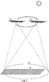
- FIG. 1 shows schematically an example of a flight vehicle 100.
- the flight vehicle 100 comprises a main body 102 and a main wing 104.
- the main body 102 includes propellers 106, skids 108, and wheels 110.
- the main wing 104 includes a solar cell panel 112.
- the main body 102 includes a battery and an antenna, which are not shown. Electric power generated by the solar cell panel 112 is stored in the battery.
- the flight vehicle 100 can fly by rotating the propellers 106 with the electric power stored in the battery.
- the flight vehicle 100 also forms a communication area 120 on the ground to provide wireless communication service for user terminals 30 in the communication area 120 by the antenna.
- the antenna may be a multi-beam antenna, for example, and the communication area 120 may be formed by a plurality of cells 122.
- the flight vehicle 100 flies in the stratosphere to provide wireless communication service for the user terminals 30 on the ground, for example.
- the flight vehicle 100 may function as a stratosphere platform.
- the user terminal 30 may be any communication terminal as long as it can communicate with the flight vehicle 100.
- the user terminal 30 is a mobile phone such as a smartphone.
- the user terminal 30 may also be a tablet terminal, a PC (Personal Computer) and the like.
- the flight vehicle 100 provides the wireless communication service for the user terminal 30 by relaying communication between the user terminal 30 and a network 20 on the ground, for example.
- the network 20 may include a core network that is provided by a telecommunication carrier.
- the network 20 may also include the Internet.
- the flight vehicle 100 may communicate with the network 20 via a gateway 22 in the communication area 120, of gateways 22 arranged in each region on the ground.
- the flight vehicle 100 may also communicate with the network 20 via a communication satellite (not shown).
- the flight vehicle 100 transmits data received from the user terminal 30 in the communication area 120 to the network 20, for example.
- the flight vehicle 100 receives data addressed to the user terminal 30 in the communication area 120 via the network 20, for example, the flight vehicle 100 also transmits the data to the user terminal 30.
- the flight vehicle 100 may be controlled by a control device 200.
- the flight vehicle 100 flies according to an instruction transmitted by the control device 200, for example.
- the instruction may be transmitted from the control device 200 to the flight vehicle 100 via the gateway 22 and the network 20.
- the instruction may be also transmitted from the control device 200 to the flight vehicle 100 via the communication satellite.
- the control device 200 controls a plurality of flight vehicles 100 to cause each of the plurality of flight vehicles 100 to cover a target area on the ground based on the communication area 120.
- the control device 200 controls the plurality of flight vehicles 100 in a mode (also referred to as 'first mode') where each of the plurality of flight vehicles 100 covers one target area, for example.
- a mode also referred to as 'first mode'
- each of the plurality of flight vehicles 100 covers one target area, for example.
- each of the plurality of flight vehicles 100 covers each target area while circling over each target area.
- the circling over the target area may also be referred to as stationary flight.
- control device 200 also controls the plurality of flight vehicles 100 in a mode (also referred to as 'second mode') where each of the plurality of target areas is covered by the plurality of flight vehicles 100.
- a mode also referred to as 'second mode'
- each of the plurality of target areas is covered by two or more flight vehicles 100.
- a coverage aspect of the target area may be different depending on time periods.
- a case where each of the plurality of target areas is covered by the two flight vehicles 100 is exemplified.
- the control device 200 divides one day into a plurality of time periods, and changes coverage forms by the two flight vehicles 100 for each time period.
- the number of time periods may be any number.
- the control device 200 divides one day into three time periods.
- the control device 200 changes coverage forms by the two flight vehicles 100 in a first half time period during the night-time, a second half time period during the night-time and a time period during the day-time.
- the first half time period during the night-time may be an example of the first time period
- the second half time period during the night-time may be an example of the second time period
- the time period during the day-time may be an example of the third time period.
- the control device 200 change coverage forms by the two flight vehicles 100 in the first 6 hours of the night-time (18:00 to 24:00), of the second 6 hours of the night-time (0:00 to 6:00), and the other 12 hours (6:00 to 18:00).
- the first 6 hours of the night-time may be an example of the first time period
- the second 6 hours of the night-time may be an example of the second time period
- the other 12 hours may be an example of the third time period.
- the control device 200 controls the two flight vehicles so that during the first time period, the first flight vehicle 100 of the two flight vehicles covers the target area while circling over the target area and the second flight vehicle 100 of the two flight vehicles does not form the communication area and flies at an altitude or by a flying method where electric power is less consumed, for example.
- the flight vehicle 100 of the present embodiment consumes electric power of the battery for each of flight and formation of the communication area 120. Of the total power consumption, a ratio of electric power that is used for formation of the communication area 120 is relatively greater. For this reason, it is possible to reduce the power consumption of the flight vehicle 100 relatively largely by causing the second flight vehicle 100 not to form the communication area.
- the control device 200 controls the two flight vehicles so that during the second time period, the second flight vehicle 100 covers the target area while circling over the target area and the first flight vehicle 100 does not form the communication area and flies at an altitude or by a flying method where electric power is less consumed.
- the control device 200 also controls the two flight vehicles 100 to cover the target area while circling over the target area during the third time period.
- control device 200 also controls the plurality of flight vehicles 100 in a mode (also referred to as 'third mode') where the plurality of flight vehicles 100 covers the target area while moving relative to the target area.
- a mode also referred to as 'third mode'
- the plurality of flight vehicles 100 covers the target area while moving relative to the target area. For example, movement that the flight vehicle 100 reaching an ending point of the target area moves to a starting point of the target area is repeated, so that the plurality of flight vehicles 100 covers the target area.
- the control device 200 may control the plurality of flight vehicles 100 in any one of the plurality of modes, in response to an instruction from an operator.
- the control device 200 may also control the plurality of flight vehicles 100 in a mode corresponding to a situation of a flight area over the target area.
- the control device 200 controls the plurality of flight vehicles 100 in the first mode.
- the control device 200 when covering the four target areas, the control device 200 causes each of the four flight vehicles 100 to cover each of the four target areas.
- the control device 200 may control the plurality of flight vehicles 100 in the third mode. For example, the control device 200 adds one flight vehicle 100 to the four flight vehicles 100, and causes the five flight vehicles 100 to cover the four target areas while moving. The five flight vehicles 100 move along a wind direction, and the flight vehicle 100 that reaches the ending point of the target area moves to the starting point of the target area against the wind direction. Flying against the wind direction requires more electric power, as compared to flying along the wind direction. However, it is possible to supply necessary electric power by stopping the formation of the communication area by the flight vehicle 100 that moves from the ending point to the starting point.
- the control device 200 may control the plurality of flight vehicles 100 in the second mode. For example, the control device 200 further adds three flight vehicles 100, and causes each two flight vehicles 100 to cover each of the four target areas.
- the control device 200 increases, electric power necessary for stationary flight increases. However, it is possible to supply necessary electric power by allotting the two flight vehicles 100 to one target area.
- the control device 200 may receive information indicative of a situation of the flight area over the target area from a weather information providing device 400 that provides weather information of each area in the sky.
- Examples of the information indicative of the situation of the flight area include wind direction information, wind speed information, wind direction prediction information, wind speed prediction information, and the like.
- the control device 200 may receive the information indicative of the situation of the flight area from the plurality of flight vehicles 100.
- the control device 200 may receive the information indicative of the situation of the flight area from the plurality of flight vehicles 100 via the gateway 22 and the network 20.
- the control device 200 may also receive the information indicative of the situation of the flight area from the plurality of flight vehicles 100 via the communication satellite.
- the flight vehicle 100 may transmit wind speed information indicative of a wind speed and wind direction information indicative of a wind direction in a flight area in which the flight vehicle 100 is flying, which are detected by a wind speed sensor, for example, to the control device 200.
- FIG. 1 shows an example where the control device 200 is equipped on the ground, but the control device 200 is not limited thereto.
- the control device 200 may be mounted on any one of the plurality of flight vehicles 100.
- the control device 200 may be mounted on the communication satellite.
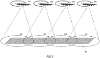
- FIG. 2 shows schematically an example of the plurality of flight vehicles 100 that is controlled in the first mode.
- the four flight vehicles 100 perform stationary flight over a target area 40 to cover the target area 40 is shown.
- the target area 40 may be arbitrarily defined.
- the target area 40 is defined, for example, by countries.
- the target area 40 may be also defined for each divisional unit defined differently in each country, such as prefectures and municipalities in Japan.
- the target area 40 may not correspond to such a division.
- the target area 40 may be defined by an administrator of the flight vehicle 100 and an operator of the control device 200.
- FIG. 2 exemplifies an aspect where the target area 40 has an elongated shape and the plurality of flight vehicles 100 is lined up in a row to cover the target area 40.
- the shape of the target area 40 is not limited thereto.
- the arrangement of the plurality of flight vehicles 100 is not limited to a row shape, and the flight vehicles may be arbitrarily arranged so as to cover the target area 40, according to a shape of the target area 40.
- the control device 200 transmits a position of an area, which is covered by each flight vehicle, of the target area 40 to each of the plurality of flight vehicles 100, for example.
- the control device 200 may also transmit a position of a flight area in which each flight vehicle performs stationary flight to each of the plurality of flight vehicles 100.
- the control device 200 may perceive positions of the plurality of flight vehicles 100 by receiving position information, which indicates a position of each of the plurality of flight vehicles 100, from each of the plurality of flight vehicles 100.
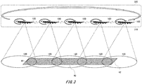
- FIG. 3 shows schematically an example of the plurality of flight vehicles 100 that is controlled in the third mode.
- the five flight vehicles 100 cover the target area 40 while moving relative to the target area 40 is shown.
- a flight area 310 indicates a flight area in which the flight vehicles 100 fly when covering the target area 40.
- a flight area 320 indicates a flight area in which the flight vehicles 100 fly when moving from an ending point 44 to a starting point 42 of the target area 40.
- the flight area 310 may be an example of the first flight area.
- the flight area 320 may be an example of the second flight area.
- the control device 200 transmits, to each of the plurality of flight vehicles 100, a position of the target area 40, positions of the starting point 42 and the ending point 44 of the target area 40, a moving route from the starting point 42 to the ending point 44, and a moving route from the ending point 44 to the starting point 42, for example.
- the control device 200 may decide the starting point 42 and the ending point 44 so that a tailwind is received in the moving route from the starting point 42 to the ending point 44, for example.
- the control device 200 may decide the moving route from the starting point 42 to the ending point 44 so as to cover the entire target area 40.
- the control device 200 may decide such a moving route from the ending point 44 to the starting point 42 that electric power required to move from the ending point 44 to the starting point 42 is reduced as much as possible. For example, the control device 200 decides, as the moving route from the ending point 44 to the starting point 42, a moving route where a wind speed of headwind is smallest in flight areas from the ending point 44 to the starting point 42. This can reduce electric power required for the movement from the ending point 44 to the starting point 42, as compared to flying the flight vehicles in a flight area where a wind speed is stronger.
- control device 200 may also decide the moving route from the ending point 44 to the starting point 42 at a lower altitude than that of the moving route from the starting point 42 to the ending point 44. Since a concentration of the air is higher and electric power necessary for flying is reduced at a lower altitude, the moving route is decided at such an altitude, so that it is possible to reduce electric power required to move from the ending point 44 to the starting point 42, as compared to flying the flight vehicles at a higher altitude.
- the flight vehicle 100 moves from the starting point 42 to the ending point 44 along the moving route from the starting point 42 to the ending point 44 while circling. That is, the flight vehicle 100 moves to shift from the starting point 42 toward the ending point 44 while circling.
- the flight vehicle 100 moves from the ending point 44 to the starting point 42 along the moving route from the ending point 44 to the starting point 42.
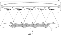
- FIG. 4 shows schematically an example of the plurality of flight vehicles 100 that is controlled in the third mode.
- FIG. 3 the example where the flight vehicle 100 moves from the starting point 42 to the ending point 44 while circling has been described.
- the flight vehicle 100 may move from the starting point 42 to the ending point 44 along the moving route from the starting point 42 to the ending point 44 without circling.
- FIG. 5 shows schematically an example of the communication area 120 that is formed by each of the plurality of flight vehicles 100.
- FIG. 5 exemplifies a plurality of communication areas 120 in a weak wind area 330 and a plurality of communication areas 120 in a strong wind area 340.
- the weak wind area 330 is an area in which a wind speed is smaller than in the strong wind area 340.
- the control device 200 controls the plurality of flight vehicles 100 in the first mode.
- FIG. 5 exemplifies the communication areas 120 formed by the four flight vehicles 100.
- FIG. 5 exemplifies the communication areas 120 formed by the five flight vehicles 100.
- the five flight vehicles 100 move along a wind direction 342 from a starting point toward an ending point of a target area.
- the flight vehicle 100 that reaches the ending point of the target area stops formation of the communication area 120, and moves from the ending point toward the starting point in an opposite direction to the wind direction 342.
- FIG. 6 shows schematically an example of the plurality of flight vehicles 100 that is controlled in the second mode. Here, an example where every two of the eight flight vehicles 100 cover each part of the target area 40 is shown. In the example shown in FIG. 6 , the control device 200 causes the two flight vehicles 100 to cover each part of the target area 40.
- FIG. 7 shows schematically an example of the two flight vehicles 100 that are controlled in the second mode during the day-time.
- the control device 200 causes each of the two flight vehicles 100 to form the communication area 120 and perform stationary flight, and then cover the target area.
- the two flight vehicles 100 form the communication area 120, so that it is possible to increase the communication capacity, as compared to a case where one flight vehicle 100 forms the communication area 120.
- FIG. 8 shows schematically an example of the two flight vehicles 100 that are controlled in the second mode during the night-time.
- the control device 200 causes the second flight vehicle 100, of the first flight vehicle 100 and the second flight vehicle 100, not to cover the target area 40 and causes the first flight vehicle 100 to cover the target area 40, and in a second half during the night-time, the control device 200 causes the first flight vehicle 100 not to cover the target area 40 and causes the second flight vehicle 100 to cover the target area 40.
- the control device 200 causes the flight vehicle 100, which does not cover the target area 40, to stop formation of the communication area 120 and to fly by a flying method where electric power consumed in flight is less than that of the flight vehicle 100 that covers the target area 40.
- the control device 200 causes the flight vehicle 100, which does not cover the target area 40, to fly by a flying method where a gliding time is longer than that in a flying method of the flight vehicle 100 that covers the target area 40.
- the example shown in FIG. 8 shows that the flight vehicle 100, which does not cover the target area 40, is gliding while circling.
- the flying method shown in FIG. 8 is exemplary. That is, the control device 200 may cause the flight vehicle 100, which does not cover the target area 40, to fly by any flying method as long as it is a flying method where electric power consumed in flight is less than that of the flight vehicle 100 that covers the target area 40.
- the control device 200 may cause the flight vehicle 100, which does not cover the target area 40, to fly at an altitude lower than an altitude at which the flight vehicle 100, which covers the target area 40, is flying.
- the control device 200 may cause the flight vehicle 100, which does not cover the target area 40, to fly at an altitude lower than an altitude at which the flight vehicle 100, which covers the target area 40, is flying and by the flying method where electric power consumed in flight is less than the flying method of the flight vehicle 100 that covers the target area 40.
- control device 200 may control the plurality of flight vehicles 100 via the network 20 and the gateway 22.
- the control device 200 may also control the plurality of flight vehicles 100 via the communication satellite.
- the control device 200 may control the plurality of flight vehicles 100 by enabling the plurality of flight vehicles 100 to communicate with each other.
- the plurality of flight vehicles 100 may communicate with each other via the communication satellite, for example.
- the plurality of flight vehicles 100 may also communicate with each other via the gateway 22.
- FIG. 9 shows schematically an example of a flow of processing that is performed by the control device 200.
- FIG. 9 shows an example of a flow of processing that is performed when the control device 200 controls the plurality of flight vehicles 100 in the different modes, according to the wind speed in the flight area in which the plurality of flight vehicles 100 flies.
- a state where there is no wind over the target area is described as a start state.
- step (which may be abbreviated as S) 102 the control device 200 controls the plurality of flight vehicles 100 in the first mode.
- Each of the plurality of flight vehicles 100 performs stationary flight over each part of the target area, thereby covering each part of the target area.
- the control device 200 determines whether the wind speed in the flight area is greater than the first threshold value. When a result of the determination is Yes, the flow proceeds to S106, and otherwise, returns to S102. Even though the wind speed is temporarily greater than the first threshold value, if the state where the wind speed is greater than the first threshold value does not continue for a predetermined time, for example, the control device 200 may determine that the wind speed is not strong, and if the wind speed is continuously greater than the first threshold value for the predetermined time, the control device may determine that the wind speed is strong.
- the control device 200 adds a spare flight vehicle to the plurality of flight vehicles 100, and controls the plurality of flight vehicles 100 in the third mode.
- the spare flight vehicle may be waiting in the sky, for example.
- the spare flight vehicle may also be waiting on the ground.
- the control device 200 determines whether the wind speed in the flight area is greater than the second threshold value. When a result of the determination is Yes, the flow proceeds to S112, and otherwise, proceeds to S110. In S110, the control device 200 determines whether the wind speed in the flight area is smaller than the first threshold value. When a result of the determination is Yes, the flow returns to S102, and otherwise, returns to S106. When returning to S102, the control device 200 may move any one of the plurality of flight vehicles 100 to a standby position, as a spare flight vehicle.
- the control device 200 adds a spare flight vehicle to the plurality of flight vehicles 100, and controls the plurality of flight vehicles 100 in the second mode.
- the spare flight vehicle may be waiting in the sky, for example.
- the spare flight vehicle may also be waiting on the ground.
- the control device 200 determines whether the wind speed in the flight area is smaller than the second threshold value. When a result of the determination is Yes, the flow returns to S106, and otherwise, returns to S112. When the flow returns to S 106, the control device 200 may move any one of the plurality of flight vehicles 100 to a standby position, as a spare flight vehicle.
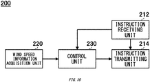
- FIG. 10 shows schematically an example of a functional configuration of the control device 200.
- the control device 200 includes an instruction receiving unit 212, an instruction transmitting unit 214, a wind speed information acquisition unit 220, and a control unit 230.
- the instruction receiving unit 212 receives a variety of instructions.
- the instruction receiving unit 212 receives an instruction to designate the target area 40, for example.
- the instruction receiving unit 212 may receive an instruction to designate the starting point 42 and the ending point 44.
- the instruction receiving unit 212 may receive an instruction to designate the moving route from the starting point 42 to the ending point 44.
- the instruction receiving unit 212 may receive an instruction to designate the moving route from the ending point 44 to the starting point 42.
- the instruction receiving unit 212 may receive an instruction that is input via an operation unit which the control device 200 includes.
- the instruction receiving unit 212 may also receive an instruction received via the network 20, via a communication unit which the control device 200 includes.
- the instruction transmitting unit 214 transmits the instruction received by the instruction receiving unit 212 to the flight vehicle 100.
- the instruction transmitting unit 214 may transmit the instruction to the plurality of flight vehicles 100.
- the instruction transmitting unit 214 may also transmit the instruction to one flight vehicle 100 of the plurality of flight vehicles 100, and the one flight vehicle 100 may transmit the instruction to the other flight vehicles 100.
- the wind speed information acquisition unit 220 acquires the wind speed information.
- the wind speed information may include the wind direction information.
- the wind speed information acquisition unit 220 may acquire the wind speed information over the target area.
- the wind speed information acquisition unit 220 may receive the wind speed information from the weather information providing device 400.
- the control unit 230 controls the plurality of flight vehicles 100.
- the control unit 230 controls the plurality of flight vehicles 100 in the first mode, for example.
- the control unit 230 may transmit a position of the target area that is covered by each of the plurality of flight vehicles 100 to each of the plurality of flight vehicles 100.
- the control unit 230 may transmit a position of the flight area in which each of the plurality of flight vehicles 100 flies to each of the plurality of flight vehicles 100.
- the control unit 230 also controls the plurality of flight vehicles 100 in the second mode, for example.
- the control unit 230 controls the first flight vehicle and the second flight vehicle so that during the first time period, the second flight vehicle of the first flight vehicle and the second flight vehicle corresponding to a first target area is caused not to cover the first target area and the first flight vehicle is caused to cover the first target area, and during the second time period, the first flight vehicle is caused not to cover the first target area and the second flight vehicle is caused to cover the first target area.
- each of the three flight vehicles 100 may be caused to cover in turn the first target area.
- the first time period and the second time period may be night-time.
- the first time period may be a first half of the night-time
- the second time period may be a second half of the night-time.
- the control unit 230 may control the first flight vehicle and the second flight vehicle so that the second flight vehicle is caused not to form the communication area 120 during the first time period and the first flight vehicle is caused not to form the communication area 120 during the second time period.
- the control unit 230 may control flying of the first flight vehicle and the second flight vehicle so that during the first time period, the second flight vehicle is caused to fly at a predetermined altitude or by a predetermined flying method where electric power consumed in flight is less than that of the first flight vehicle that covers the first target area, and during the second time period, the first flight vehicle is caused to fly at a predetermined altitude or a predetermined flying method where electric power consumed in flight is less than that of the second flight vehicle that covers the first target area.
- the predetermined altitude at which electric power consumed in flight is less than that of the first flight vehicle that covers the first target area may be an altitude lower than an altitude at which the first flight vehicle is flying
- the predetermined altitude at which electric power consumed in flight is less than that of the second flight vehicle that covers the first target area may be an altitude lower than an altitude at which the second flight vehicle is flying.
- the predetermined flying method where electric power consumed in flight is less than that of the first flight vehicle that covers the first target area may be a method where a gliding time is longer than that in a flying method of the first flight vehicle
- the predetermined flying method where electric power consumed in flight is less than that of the second flight vehicle that covers the first target area may be a method where a gliding time is longer than that in a flying method of the second flight vehicle.
- the control unit 230 may control the first flight vehicle and the second flight vehicle so that both the first flight vehicle and the second flight vehicle are caused to cover the first target area during the third time period.
- the third time period may be any time other than the night-time.
- the control unit 230 also controls the plurality of flight vehicles 100 in the third mode, for example.
- the control unit 230 may control the plurality of flight vehicles 100 so that the communication area 120 of each of the plurality of flight vehicles 100 moves while covering a part of the target area and the target area is entirely covered by the plurality of the communication areas 120 of the plurality of flight vehicles 100.
- the control unit 230 may control the flight vehicle so that the flight vehicle 100 that reaches an ending point of the target area flies in a second flight area different from the first flight area in which the flight vehicle flies while covering the target area and then moves to a starting point of the target area.
- a wind direction in the first flight area may follow a flying direction of the flight vehicle that flies while covering the target area, and a wind direction in the second flight area may be opposite to the wind direction in the first flight area.
- the control unit 230 may control the flight vehicle so as to fly in the second flight area where a wind speed is smaller than in the first flight area and to move the starting point of the target area.
- the control unit 230 may cause the flight vehicle 100 not to form the communication area while the flight vehicle 100 is flying in the second flight area.
- the control unit 230 may acquire the wind speed information from the wind speed information acquisition unit 220, and control the plurality of flight vehicles 100, based on the wind speed information. For example, the control unit 230 controls the plurality of flight vehicles 100 in the first mode when a wind speed indicated by the wind speed information is smaller than the first threshold value. The control unit 230 also controls the plurality of flight vehicles 100 in the third mode when the wind speed indicated by the wind speed information is greater than the first threshold value and is smaller than the second threshold value larger than the first threshold value. The control unit 230 also controls the plurality of flight vehicles 100 in the second mode when the wind speed indicated by the wind speed information is greater than the second threshold value.
- the control unit 230 may move some of the plurality of flight vehicles 100 in the Northern Hemisphere to the Southern Hemisphere.
- the control unit 230 may move some of the plurality of flight vehicles 100 in the Southern Hemisphere to the Northern Hemisphere.
- the flight vehicle 100 after the movement may cover a designated area, and wait at a standby position, as a spare flight vehicle. Thereby, it is possible to increase the number of the flight vehicles 100 in a region where the season is winter and an amount of electric power generated by sunlight is small.
- FIG. 11 shows schematically an example of a functional configuration of a control device 130 included in the flight vehicle 100.
- the control device 130 comprises an electric power receiving unit 132, a battery 134, a wireless communication unit 136, a wind speed information transmitting unit 138, and a control unit 140.
- the electric power receiving unit 132 receives electric power generated by the solar cell panel 112.
- the electric power receiving unit 132 stores the received electric power in the battery 134.
- the wireless communication unit 136 performs diverse communications by using the electric power stored in the battery 134.
- the wireless communication unit 136 forms, for example, the communication area 120.
- the wireless communication unit 136 may communicate with the control device 200.
- the wireless communication unit 136 may communicate with the other flight vehicles 100.
- the wireless communication unit 136 may communicate with the communication satellite.
- the wind speed information transmitting unit 138 transmits the wind speed information detected by the wind speed sensor 114 to the control device 200 and the like.
- the wind speed information transmitting unit 138 may transmit the wind speed information via the wireless communication unit 136.
- the control unit 140 controls flying and the like of the flight vehicle 100.
- the control unit 140 may control flying and the like of the flight vehicle 100 according to an instruction from the control device 200.
- the control unit 140 when receiving a control signal for control in the second mode from the control device 200, the control unit 140 causes the flight vehicle to fly at the predetermined altitude or by the predetermined flying method where during the first time period, the target area on the ground is covered by the communication area 120, and during the second time period, the communication area 120 is not formed and electric power consumed in flight is less than that in a case where the target area is covered.
- the control unit 140 when receiving a control signal for control in the third mode from the control device 200, the control unit 140 also controls the flight vehicles 100 so that the communication area 120 of each of the plurality of flight vehicles 100 including another flight vehicle 100 moves while covering a part of the target area and the target area is entirely covered by the plurality of the communication areas 120 of the plurality of flight vehicles 100.
- the control unit 140 may control the flight vehicle 100 so that the flight vehicle 100 that reaches an ending point of the target area flies in the second flight area different from the first flight area in which the flight vehicle flies while covering the target area and then moves to the starting point of the target area.
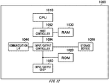
- FIG. 12 shows schematically an example of a computer 1000 functioning as the control device 200.
- the computer 1000 in accordance with the present embodiment includes a CPU peripheral unit including a CPU 1010 and a RAM 1030, which are mutually connected by a host controller 1092, and an input/output unit including a ROM 1020, a communication I/F 1040, a storage device 1050 and an input/output chip 1080, which are connected to the host controller 1092 by an input/output controller 1094.
- the CPU 1010 operates based on programs stored in the ROM 1020 and the RAM 1030, thereby controlling each unit.
- the communication I/F 1040 communicates with other devices via the network.
- the communication I/F 1040 also functions as hardware for performing communication.
- the storage device 1050 may be a hard disk drive, a solid state disk, a solid state drive and the like, and stores programs and data that are used by the CPU 1010.
- the ROM 1020 stores therein a boot program that is performed by the computer 1000 at the time of activation, and a program depending on the hardware of the computer 1000.
- the input/output chip 1080 connects various input/output units to the input/output controller 1094 via a USB port, a parallel port, a serial port, a keyboard port, a mouse port and the like.
- the program that is provided to the storage device 1050 via the RAM 1030 is provided with being stored in a recording medium such as an IC card by a user.
- the program is read from the recording medium, installed into the storage device 1050 via the RAM 1030, and performed by the CPU 1010.
- the program installed in the computer 1000 to cause the computer 1000 to function as the control device 200 activates the CPU 1010 and the like to cause the computer 1000 to function as the respective units of the control device 200.
- the information processing described in the programs functions as the instruction receiving unit 212, the instruction transmitting unit 214, the wind speed information acquisition unit 220, and the control unit 230, which are specific means in which software and various types of hardware resources cooperate with each other, as the programs are read into the computer 1000.
- the specific means implements calculation or processing of information according to a use purpose of the computer 1000 of the present embodiment, so that the specific control device 200 is established according to the use purpose.
- FIG. 13 shows schematically an example of a computer 1100 functioning as the control device 130.
- the computer 1100 in accordance with the present embodiment includes a CPU peripheral unit including a CPU 1110 and a RAM 1130, which are mutually connected by a host controller 1192, and an input/output unit including a ROM 1120, a communication I/F 1140, a storage device 1150, an input/output chip 1180 and a wind speed sensor 1182, which are connected to the host controller 1192 by an input/output controller 1194.
- a CPU peripheral unit including a CPU 1110 and a RAM 1130, which are mutually connected by a host controller 1192
- an input/output unit including a ROM 1120, a communication I/F 1140, a storage device 1150, an input/output chip 1180 and a wind speed sensor 1182, which are connected to the host controller 1192 by an input/output controller 1194.
- the CPU 1110 operates based on programs stored in the ROM 1120 and the RAM 1130, thereby controlling each unit.
- the communication I/F 1140 communicates with other devices via the network.
- the communication I/F 1140 also functions as hardware for performing communication.
- the storage device 1150 may be a hard disk drive, a solid state disk, a solid state drive and the like, and stores programs and data that are used by the CPU 1110.
- the ROM 1120 stores therein a boot program that is performed by the computer 1100 at the time of activation, and a program depending on the hardware of the computer 1100.
- the input/output chip 1180 connects various input/output units to the input/output controller 1194 via a USB port, a parallel port, a serial port, a keyboard port, a mouse port and the like.
- the wind speed sensor 1182 may be a sensor for detecting the wind speed in the flight area in which the flight vehicle 100 having the control device 130 mounted thereon flies.
- the program that is provided to the storage device 1150 via the RAM 1130 is provided with being stored in a recording medium such as an IC card by a user.
- the program is read from the recording medium, installed into the storage device 1150 via the RAM 1130, and performed by the CPU 1110.
- the program installed in the computer 1100 to cause the computer 1100 to function as the control device 130 activates the CPU 1110 and the like to cause the computer 1100 to function as the respective units of the control device 130.
- the information processing described in the programs functions as the electric power receiving unit 132, the battery 134, the wireless communication unit 136, the wind speed information transmitting unit 138, and the control unit 140, which are specific means in which software and various types of hardware resources cooperate with each other, as the programs are read into the computer 1100.
- the specific means implements calculation or processing of information according to a use purpose of the computer 1100 of the present embodiment, so that the specific control device 130 is established according to the use purpose.
Landscapes
- Engineering & Computer Science (AREA)
- Aviation & Aerospace Engineering (AREA)
- Physics & Mathematics (AREA)
- General Physics & Mathematics (AREA)
- Chemical & Material Sciences (AREA)
- Combustion & Propulsion (AREA)
- Signal Processing (AREA)
- Computer Networks & Wireless Communication (AREA)
- Remote Sensing (AREA)
- Automation & Control Theory (AREA)
- Radar, Positioning & Navigation (AREA)
- Astronomy & Astrophysics (AREA)
- Mechanical Engineering (AREA)
- Control Of Position, Course, Altitude, Or Attitude Of Moving Bodies (AREA)
- Life Sciences & Earth Sciences (AREA)
- Atmospheric Sciences (AREA)
- Traffic Control Systems (AREA)
- Mobile Radio Communication Systems (AREA)
- Radio Relay Systems (AREA)
Abstract
Description
- The present invention relates to a control device, a program, a control method, and a flight vehicle.
- Known is a flight vehicle that includes an antenna and flies in the stratosphere, so as to provide a stratosphere platform (for example, refer to Patent Document 1).
- Patent Document 1: Japanese Unexamined Patent Application Publication No.
2002-211496 - It is preferable to provide technology capable of covering appropriately a target area on the ground even though an airstream in a flight area in which a flight vehicle is flying changes.
- A first aspect of the present invention provides a control device for controlling a flight vehicle including a solar cell panel, and an antenna for forming a communication area on the ground to provide wireless communication service for a user terminal in the communication area by using electric power generated by the solar cell panel. The control device may comprise a control unit for controlling a first flight vehicle and a second flight vehicle so that during a first time period, the second flight vehicle of the first flight vehicle and the second flight vehicle is caused not to cover a first target area and the first flight vehicle is caused to cover the first target area, and during a second time period following the first time period, the first flight vehicle is caused not to cover the first target area and the second flight vehicle is caused to cover the first target area.
- The control unit may control the first flight vehicle and the second flight vehicle so that the second flight vehicle is caused not to form the communication area during the first time period and the first flight vehicle is caused not to form the communication area during the second time period. The control unit may control flying of the first flight vehicle and the second flight vehicle so that during the first time period, the second flight vehicle is caused to fly at a predetermined altitude or by a predetermined flying method where electric power consumed in flight is less than that of the first flight vehicle that covers the first target area, and during the second time period, the first flight vehicle is caused to fly at a predetermined altitude or by a predetermined flying method where electric power consumed in flight is less than that of the second flight vehicle that covers the first target area. The predetermined altitude at which electric power consumed in flight is less than that of the first flight vehicle that covers the first target area may be an altitude lower than an altitude at which the first flight vehicle is flying, and the predetermined altitude at which electric power consumed in flight is less than that of the second flight vehicle that covers the first target area may be an altitude lower than an altitude at which the second flight vehicle is flying. The predetermined flying method where electric power consumed in flight is less than that of the first flight vehicle that covers the first target area may be a method where a gliding time is longer than that in a flying method of the first flight vehicle, and the predetermined flying method where electric power consumed in flight is less than that of the second flight vehicle that covers the first target area may be a method where a gliding time is longer than that in a flying method of the second flight vehicle.
- The control unit may control the first flight vehicle and the second flight vehicle so that both the first flight vehicle and the second flight vehicle are caused to cover the first target area during a third time period. The first time period and the second time period may be night-time and the third time period may be any time other than night-time. The first time period and the second time period may be night-time. The first time period may be a first half of the night-time, and the second time period may be a second half of the night-time.
- The control device may comprise a wind speed information acquisition unit for acquiring wind speed information indicative of a wind speed in a flight area where each of a plurality of flight vehicles including the first flight vehicle and the second flight vehicle is flying, and when a wind speed in the flight area where the first flight vehicle is flying is smaller than a first threshold value, the control unit may control the first flight vehicle in a first mode controlling so that the first target area is covered only by the first flight vehicle, and when the wind speed in the flight area where the first flight vehicle is flying is greater than the first threshold value, the control unit may control the first flight vehicle and the second flight vehicle in a second mode controlling so that the second flight vehicle is caused not to cover the first target area and the first flight vehicle is caused to cover the first target area during the first time period, and the first flight vehicle is caused not to cover the first target area and the second flight vehicle is caused to cover the first target area during the second time period. When the wind speed in the flight area where the first flight vehicle is flying is greater than a second threshold value larger than the first threshold value, the control unit may control the first flight vehicle and the second flight vehicle in the second mode, and when the wind speed in the flight area where the first flight vehicle is flying is greater than the first threshold value and is smaller than the second threshold value, the control unit may control a plurality of flight vehicles including the first flight vehicle and the second flight vehicle in a third mode where the plurality of flight vehicles is controlled so that the communication area of each of the plurality of flight vehicles moves while covering a part of a second target area including the first target area, the second target area is entirely covered by a plurality of the communication areas of the plurality of flight vehicles, and the flight vehicle that reaches an ending point of the second target area flies in a second flight area different from a first flight area in which the flight vehicle flies while covering the second target area and then moves to a starting point of the second target area. The wind speed information acquisition unit may acquire the wind speed information that is derived based on a wind speed detected by a wind speed sensor provided to each of the plurality of flight vehicles. During summer in the Northern Hemisphere and winter in the Southern Hemisphere, the control unit may cause the second flight vehicle to fly in a flight area over the Southern Hemisphere, and during winter in the Northern Hemisphere and summer in the Southern Hemisphere, the control unit may cause the second flight vehicle to fly in a flight area over the Northern Hemisphere. The control device may be arranged on the ground. The control device may also be mounted on the first flight vehicle.
- A second aspect of the present invention provides a control device for controlling a flight vehicle including an antenna for forming a communication area on the ground to provide wireless communication service for a user terminal in the communication area. The control device may comprise a control unit for controlling a plurality of flight vehicles so that a communication area of each of the plurality of flight vehicles moves while covering a part of a predetermined target area and the target area is entirely covered by a plurality of the communication areas of the plurality of flight vehicles. The control unit may control the flight vehicle so that the flight vehicle that reaches an ending point of the target area flies in a second flight area different from a first flight area in which the flight vehicle flies while covering the target area and then moves to a starting point of the target area.
- A wind direction in the first flight area may follow a flying direction of the flight vehicle that flies while covering the target area, and a wind direction in the second flight area may be opposite to the wind direction in the first flight area. The control unit may control the flight vehicle so as to fly in the second flight area where a wind speed is smaller than in the first flight area and to move the starting point of the target area. The control unit may cause the flight vehicle not to form the communication area while the flight vehicle is flying in the second flight area.
- A third aspect of the present invention provides a program for causing a computer to function as the control device.
- A fourth aspect of the present invention provides a control method of controlling a flight vehicle including a solar cell panel, and an antenna for forming a communication area on the ground to provide wireless communication service for a user terminal in the communication area by using electric power generated by the solar cell panel. The control method may comprise controlling a first flight vehicle and a second flight vehicle so that during a first time period, the second flight vehicle of the first flight vehicle and the second flight vehicle corresponding to a first target area is caused not to cover the first target area and the first flight vehicle is caused to cover the first target area, and during a second time period following the first time period, the first flight vehicle is caused not to cover the first target area and the second flight vehicle is caused to cover the first target area.
- A fifth aspect of the present invention provides a control method of controlling a flight vehicle including an antenna for forming a communication area on the ground to provide wireless communication service for a user terminal in the communication area. The control method may comprise controlling a plurality of flight vehicles so that a communication area of each of the plurality of flight vehicles moves while covering a part of a predetermined target area and the target area is entirely covered by a plurality of the communication areas of the plurality of flight vehicles. The controlling may control the flight vehicle so that the flight vehicle that reaches an ending point of the target area flies in a second flight area different from a first flight area in which the flight vehicle flies while covering the target area and then moves to a starting point of the target area.
- A sixth aspect of the present invention provides a flight vehicle. The flight vehicle may comprise a solar cell panel. The flight vehicle may comprise an antenna for forming a communication area on the ground to provide wireless communication service for a user terminal in the communication area by using electric power generated by the solar cell panel. The flight vehicle may comprise a control unit for causing the flight vehicle to fly at a predetermined altitude or by a predetermined flying method where during a first time period, a target area on the ground is covered by a communication area, and during a second time period following the first time period, a communication area is not formed and electric power consumed in flight is less than that in a case where the target area is covered.
- A seventh aspect of the present invention provides a flight vehicle. The flight vehicle may comprise an antenna for forming a communication area on the ground to provide wireless communication service for a user terminal in the communication area. The flight vehicle may comprise a control unit for controlling the flight vehicle so that a communication area of each of a plurality of flight vehicles including another flight vehicle moves while covering a part of a predetermined target area and the target area is entirely covered by a plurality of the communication areas of the plurality of flight vehicles. The control unit may control the flight vehicle so that the flight vehicle that reaches an ending point of the target area flies in a second flight area different from a first flight area in which the flight vehicle flies while covering the target area and then moves to a starting point of the target area.
- The summary clause does not necessarily describe all necessary features of the embodiments of the present invention. The present invention may also be a sub-combination of the features described above.
-
-
FIG. 1 shows schematically an example of aflight vehicle 100. -
FIG. 2 shows schematically an example of a plurality offlight vehicles 100 that is controlled in a first mode. -
FIG. 3 shows schematically an example of the plurality offlight vehicles 100 that is controlled in a third mode. -
FIG. 4 shows schematically an example of the plurality offlight vehicles 100 that is controlled in the third mode. -
FIG. 5 shows schematically an example of acommunication area 120 that is formed by each of the plurality offlight vehicles 100. -
FIG. 6 shows schematically an example of the plurality offlight vehicles 100 that is controlled in a second mode. -
FIG. 7 shows schematically an example of twoflight vehicles 100 that are controlled in the second mode during the day-time. -
FIG. 8 shows schematically an example of twoflight vehicles 100 that are controlled in the second mode during the night-time. -
FIG. 9 shows schematically an example of a flow of processing that is performed by acontrol device 200. -
FIG. 10 shows schematically an example of a functional configuration of thecontrol device 200. -
FIG. 11 shows schematically an example of a functional configuration of acontrol device 130 mounted in aflight vehicle 100. -
FIG. 12 shows schematically an example of a hardware configuration of acomputer 1000 functioning as thecontrol device 200. -
FIG. 13 shows schematically an example of a hardware configuration of acomputer 1100 functioning as thecontrol device 130. - Hereinafter, the present invention will be described through embodiments of the invention. However, the following embodiments do not limit the invention defined in the claims. Also, all combinations of features described in the embodiments are not necessarily essential to solutions of the invention.
-
FIG. 1 shows schematically an example of aflight vehicle 100. Theflight vehicle 100 comprises amain body 102 and amain wing 104. Themain body 102 includespropellers 106, skids 108, andwheels 110. Themain wing 104 includes asolar cell panel 112. - The
main body 102 includes a battery and an antenna, which are not shown. Electric power generated by thesolar cell panel 112 is stored in the battery. Theflight vehicle 100 can fly by rotating thepropellers 106 with the electric power stored in the battery. Theflight vehicle 100 also forms acommunication area 120 on the ground to provide wireless communication service foruser terminals 30 in thecommunication area 120 by the antenna. The antenna may be a multi-beam antenna, for example, and thecommunication area 120 may be formed by a plurality ofcells 122. Theflight vehicle 100 flies in the stratosphere to provide wireless communication service for theuser terminals 30 on the ground, for example. Theflight vehicle 100 may function as a stratosphere platform. - The
user terminal 30 may be any communication terminal as long as it can communicate with theflight vehicle 100. For example, theuser terminal 30 is a mobile phone such as a smartphone. Theuser terminal 30 may also be a tablet terminal, a PC (Personal Computer) and the like. - The
flight vehicle 100 provides the wireless communication service for theuser terminal 30 by relaying communication between theuser terminal 30 and anetwork 20 on the ground, for example. Thenetwork 20 may include a core network that is provided by a telecommunication carrier. Thenetwork 20 may also include the Internet. - The
flight vehicle 100 may communicate with thenetwork 20 via agateway 22 in thecommunication area 120, ofgateways 22 arranged in each region on the ground. For example, theflight vehicle 100 may also communicate with thenetwork 20 via a communication satellite (not shown). - The
flight vehicle 100 transmits data received from theuser terminal 30 in thecommunication area 120 to thenetwork 20, for example. When theflight vehicle 100 receives data addressed to theuser terminal 30 in thecommunication area 120 via thenetwork 20, for example, theflight vehicle 100 also transmits the data to theuser terminal 30. - The
flight vehicle 100 may be controlled by acontrol device 200. Theflight vehicle 100 flies according to an instruction transmitted by thecontrol device 200, for example. The instruction may be transmitted from thecontrol device 200 to theflight vehicle 100 via thegateway 22 and thenetwork 20. The instruction may be also transmitted from thecontrol device 200 to theflight vehicle 100 via the communication satellite. - The
control device 200 controls a plurality offlight vehicles 100 to cause each of the plurality offlight vehicles 100 to cover a target area on the ground based on thecommunication area 120. Thecontrol device 200 controls the plurality offlight vehicles 100 in a mode (also referred to as 'first mode') where each of the plurality offlight vehicles 100 covers one target area, for example. In the first mode, each of the plurality offlight vehicles 100 covers each target area while circling over each target area. The circling over the target area may also be referred to as stationary flight. - For example, the
control device 200 also controls the plurality offlight vehicles 100 in a mode (also referred to as 'second mode') where each of the plurality of target areas is covered by the plurality offlight vehicles 100. In the second mode, each of the plurality of target areas is covered by two ormore flight vehicles 100. - In the second mode, a coverage aspect of the target area may be different depending on time periods. Herein, a case where each of the plurality of target areas is covered by the two
flight vehicles 100 is exemplified. - The
control device 200 divides one day into a plurality of time periods, and changes coverage forms by the twoflight vehicles 100 for each time period. The number of time periods may be any number. For example, thecontrol device 200 divides one day into three time periods. For example, thecontrol device 200 changes coverage forms by the twoflight vehicles 100 in a first half time period during the night-time, a second half time period during the night-time and a time period during the day-time. The first half time period during the night-time may be an example of the first time period, the second half time period during the night-time may be an example of the second time period, and the time period during the day-time may be an example of the third time period. - As an example, the
control device 200 change coverage forms by the twoflight vehicles 100 in the first 6 hours of the night-time (18:00 to 24:00), of the second 6 hours of the night-time (0:00 to 6:00), and the other 12 hours (6:00 to 18:00). The first 6 hours of the night-time may be an example of the first time period, the second 6 hours of the night-time may be an example of the second time period, and the other 12 hours may be an example of the third time period. - The
control device 200 controls the two flight vehicles so that during the first time period, thefirst flight vehicle 100 of the two flight vehicles covers the target area while circling over the target area and thesecond flight vehicle 100 of the two flight vehicles does not form the communication area and flies at an altitude or by a flying method where electric power is less consumed, for example. Theflight vehicle 100 of the present embodiment consumes electric power of the battery for each of flight and formation of thecommunication area 120. Of the total power consumption, a ratio of electric power that is used for formation of thecommunication area 120 is relatively greater. For this reason, it is possible to reduce the power consumption of theflight vehicle 100 relatively largely by causing thesecond flight vehicle 100 not to form the communication area. - The
control device 200 controls the two flight vehicles so that during the second time period, thesecond flight vehicle 100 covers the target area while circling over the target area and thefirst flight vehicle 100 does not form the communication area and flies at an altitude or by a flying method where electric power is less consumed. Thecontrol device 200 also controls the twoflight vehicles 100 to cover the target area while circling over the target area during the third time period. By the above control, during the time period in which electric power can be generated by sunlight, it is possible to increase a communication capacity by causing the twoflight vehicles 100 to cover the target area,, as compared to a case where oneflight vehicle 100 covers the target area. During the time period in which electric power cannot be generated by sunlight, electric power can be also saved by causing the twoflight vehicles 100 to alternately cover the target area. Thus, it is possible to reduce a possibility that electric power stored in the battery will be exhausted at night. - For example, the
control device 200 also controls the plurality offlight vehicles 100 in a mode (also referred to as 'third mode') where the plurality offlight vehicles 100 covers the target area while moving relative to the target area. In the third mode, the plurality offlight vehicles 100 covers the target area while moving relative to the target area. For example, movement that theflight vehicle 100 reaching an ending point of the target area moves to a starting point of the target area is repeated, so that the plurality offlight vehicles 100 covers the target area. - The
control device 200 may control the plurality offlight vehicles 100 in any one of the plurality of modes, in response to an instruction from an operator. Thecontrol device 200 may also control the plurality offlight vehicles 100 in a mode corresponding to a situation of a flight area over the target area. - For example, in a case where a wind speed in the flight area is smaller than a first threshold value, the
control device 200 controls the plurality offlight vehicles 100 in the first mode. As a specific example, when covering the four target areas, thecontrol device 200 causes each of the fourflight vehicles 100 to cover each of the four target areas. - In a case where the wind speed in the flight area becomes greater than the first threshold value, the
control device 200 may control the plurality offlight vehicles 100 in the third mode. For example, thecontrol device 200 adds oneflight vehicle 100 to the fourflight vehicles 100, and causes the fiveflight vehicles 100 to cover the four target areas while moving. The fiveflight vehicles 100 move along a wind direction, and theflight vehicle 100 that reaches the ending point of the target area moves to the starting point of the target area against the wind direction. Flying against the wind direction requires more electric power, as compared to flying along the wind direction. However, it is possible to supply necessary electric power by stopping the formation of the communication area by theflight vehicle 100 that moves from the ending point to the starting point. - In a case where the wind speed in the flight area is greater than a second threshold value larger than the first threshold value, the
control device 200 may control the plurality offlight vehicles 100 in the second mode. For example, thecontrol device 200 further adds threeflight vehicles 100, and causes each twoflight vehicles 100 to cover each of the four target areas. When the wind speed increases, electric power necessary for stationary flight increases. However, it is possible to supply necessary electric power by allotting the twoflight vehicles 100 to one target area. - The
control device 200 may receive information indicative of a situation of the flight area over the target area from a weatherinformation providing device 400 that provides weather information of each area in the sky. Examples of the information indicative of the situation of the flight area include wind direction information, wind speed information, wind direction prediction information, wind speed prediction information, and the like. - The
control device 200 may receive the information indicative of the situation of the flight area from the plurality offlight vehicles 100. Thecontrol device 200 may receive the information indicative of the situation of the flight area from the plurality offlight vehicles 100 via thegateway 22 and thenetwork 20. Thecontrol device 200 may also receive the information indicative of the situation of the flight area from the plurality offlight vehicles 100 via the communication satellite. Theflight vehicle 100 may transmit wind speed information indicative of a wind speed and wind direction information indicative of a wind direction in a flight area in which theflight vehicle 100 is flying, which are detected by a wind speed sensor, for example, to thecontrol device 200. -
FIG. 1 shows an example where thecontrol device 200 is equipped on the ground, but thecontrol device 200 is not limited thereto. For example, thecontrol device 200 may be mounted on any one of the plurality offlight vehicles 100. Thecontrol device 200 may be mounted on the communication satellite. -
FIG. 2 shows schematically an example of the plurality offlight vehicles 100 that is controlled in the first mode. Here, an example where the fourflight vehicles 100 perform stationary flight over atarget area 40 to cover thetarget area 40 is shown. - The
target area 40 may be arbitrarily defined. Thetarget area 40 is defined, for example, by countries. For example, thetarget area 40 may be also defined for each divisional unit defined differently in each country, such as prefectures and municipalities in Japan. Thetarget area 40 may not correspond to such a division. For example, thetarget area 40 may be defined by an administrator of theflight vehicle 100 and an operator of thecontrol device 200. -
FIG. 2 exemplifies an aspect where thetarget area 40 has an elongated shape and the plurality offlight vehicles 100 is lined up in a row to cover thetarget area 40. However, the shape of thetarget area 40 is not limited thereto. The arrangement of the plurality offlight vehicles 100 is not limited to a row shape, and the flight vehicles may be arbitrarily arranged so as to cover thetarget area 40, according to a shape of thetarget area 40. - The
control device 200 transmits a position of an area, which is covered by each flight vehicle, of thetarget area 40 to each of the plurality offlight vehicles 100, for example. Thecontrol device 200 may also transmit a position of a flight area in which each flight vehicle performs stationary flight to each of the plurality offlight vehicles 100. Thecontrol device 200 may perceive positions of the plurality offlight vehicles 100 by receiving position information, which indicates a position of each of the plurality offlight vehicles 100, from each of the plurality offlight vehicles 100. -
FIG. 3 shows schematically an example of the plurality offlight vehicles 100 that is controlled in the third mode. Here, an example where the fiveflight vehicles 100 cover thetarget area 40 while moving relative to thetarget area 40 is shown. - A
flight area 310 indicates a flight area in which theflight vehicles 100 fly when covering thetarget area 40. Aflight area 320 indicates a flight area in which theflight vehicles 100 fly when moving from anending point 44 to astarting point 42 of thetarget area 40. Theflight area 310 may be an example of the first flight area. Theflight area 320 may be an example of the second flight area. - The
control device 200 transmits, to each of the plurality offlight vehicles 100, a position of thetarget area 40, positions of thestarting point 42 and theending point 44 of thetarget area 40, a moving route from thestarting point 42 to theending point 44, and a moving route from theending point 44 to thestarting point 42, for example. Thecontrol device 200 may decide thestarting point 42 and theending point 44 so that a tailwind is received in the moving route from thestarting point 42 to theending point 44, for example. Thecontrol device 200 may decide the moving route from thestarting point 42 to theending point 44 so as to cover theentire target area 40. - The
control device 200 may decide such a moving route from theending point 44 to thestarting point 42 that electric power required to move from theending point 44 to thestarting point 42 is reduced as much as possible. For example, thecontrol device 200 decides, as the moving route from theending point 44 to thestarting point 42, a moving route where a wind speed of headwind is smallest in flight areas from theending point 44 to thestarting point 42. This can reduce electric power required for the movement from theending point 44 to thestarting point 42, as compared to flying the flight vehicles in a flight area where a wind speed is stronger. - For example, the
control device 200 may also decide the moving route from theending point 44 to thestarting point 42 at a lower altitude than that of the moving route from thestarting point 42 to theending point 44. Since a concentration of the air is higher and electric power necessary for flying is reduced at a lower altitude, the moving route is decided at such an altitude, so that it is possible to reduce electric power required to move from theending point 44 to thestarting point 42, as compared to flying the flight vehicles at a higher altitude. - In the example shown in
FIG. 3 , theflight vehicle 100 moves from thestarting point 42 to theending point 44 along the moving route from thestarting point 42 to theending point 44 while circling. That is, theflight vehicle 100 moves to shift from thestarting point 42 toward theending point 44 while circling. When reaching theending point 44, theflight vehicle 100 moves from theending point 44 to thestarting point 42 along the moving route from theending point 44 to thestarting point 42. -
FIG. 4 shows schematically an example of the plurality offlight vehicles 100 that is controlled in the third mode. Here, differences fromFIG. 3 are mainly described. InFIG. 3 , the example where theflight vehicle 100 moves from thestarting point 42 to theending point 44 while circling has been described. However, as shown inFIG. 4 , theflight vehicle 100 may move from thestarting point 42 to theending point 44 along the moving route from thestarting point 42 to theending point 44 without circling. -
FIG. 5 shows schematically an example of thecommunication area 120 that is formed by each of the plurality offlight vehicles 100.FIG. 5 exemplifies a plurality ofcommunication areas 120 in aweak wind area 330 and a plurality ofcommunication areas 120 in astrong wind area 340. Theweak wind area 330 is an area in which a wind speed is smaller than in thestrong wind area 340. - In the
weak wind area 330, thecontrol device 200 controls the plurality offlight vehicles 100 in the first mode.FIG. 5 exemplifies thecommunication areas 120 formed by the fourflight vehicles 100. - In the
strong wind area 340, thecontrol device 200 controls the plurality offlight vehicles 100 in the third mode.FIG. 5 exemplifies thecommunication areas 120 formed by the fiveflight vehicles 100. The fiveflight vehicles 100 move along awind direction 342 from a starting point toward an ending point of a target area. Theflight vehicle 100 that reaches the ending point of the target area stops formation of thecommunication area 120, and moves from the ending point toward the starting point in an opposite direction to thewind direction 342. -
FIG. 6 shows schematically an example of the plurality offlight vehicles 100 that is controlled in the second mode. Here, an example where every two of the eightflight vehicles 100 cover each part of thetarget area 40 is shown. In the example shown inFIG. 6 , thecontrol device 200 causes the twoflight vehicles 100 to cover each part of thetarget area 40. -
FIG. 7 shows schematically an example of the twoflight vehicles 100 that are controlled in the second mode during the day-time. Thecontrol device 200 causes each of the twoflight vehicles 100 to form thecommunication area 120 and perform stationary flight, and then cover the target area. The twoflight vehicles 100 form thecommunication area 120, so that it is possible to increase the communication capacity, as compared to a case where oneflight vehicle 100 forms thecommunication area 120. -
FIG. 8 shows schematically an example of the twoflight vehicles 100 that are controlled in the second mode during the night-time. In a first half during the night-time, thecontrol device 200 causes thesecond flight vehicle 100, of thefirst flight vehicle 100 and thesecond flight vehicle 100, not to cover thetarget area 40 and causes thefirst flight vehicle 100 to cover thetarget area 40, and in a second half during the night-time, thecontrol device 200 causes thefirst flight vehicle 100 not to cover thetarget area 40 and causes thesecond flight vehicle 100 to cover thetarget area 40. - The
control device 200 causes theflight vehicle 100, which does not cover thetarget area 40, to stop formation of thecommunication area 120 and to fly by a flying method where electric power consumed in flight is less than that of theflight vehicle 100 that covers thetarget area 40. For example, thecontrol device 200 causes theflight vehicle 100, which does not cover thetarget area 40, to fly by a flying method where a gliding time is longer than that in a flying method of theflight vehicle 100 that covers thetarget area 40. The example shown inFIG. 8 shows that theflight vehicle 100, which does not cover thetarget area 40, is gliding while circling. The flying method shown inFIG. 8 is exemplary. That is, thecontrol device 200 may cause theflight vehicle 100, which does not cover thetarget area 40, to fly by any flying method as long as it is a flying method where electric power consumed in flight is less than that of theflight vehicle 100 that covers thetarget area 40. - The
control device 200 may cause theflight vehicle 100, which does not cover thetarget area 40, to fly at an altitude lower than an altitude at which theflight vehicle 100, which covers thetarget area 40, is flying. Thecontrol device 200 may cause theflight vehicle 100, which does not cover thetarget area 40, to fly at an altitude lower than an altitude at which theflight vehicle 100, which covers thetarget area 40, is flying and by the flying method where electric power consumed in flight is less than the flying method of theflight vehicle 100 that covers thetarget area 40. - In the examples shown in
FIGS. 2 to 8 , in a case where thecontrol device 200 is equipped on the ground, thecontrol device 200 may control the plurality offlight vehicles 100 via thenetwork 20 and thegateway 22. Thecontrol device 200 may also control the plurality offlight vehicles 100 via the communication satellite. - In the examples shown in
FIGS. 2 to 8 , in a case where thecontrol device 200 is mounted on any one of the plurality offlight vehicles 100, thecontrol device 200 may control the plurality offlight vehicles 100 by enabling the plurality offlight vehicles 100 to communicate with each other. The plurality offlight vehicles 100 may communicate with each other via the communication satellite, for example. The plurality offlight vehicles 100 may also communicate with each other via thegateway 22. -
FIG. 9 shows schematically an example of a flow of processing that is performed by thecontrol device 200.FIG. 9 shows an example of a flow of processing that is performed when thecontrol device 200 controls the plurality offlight vehicles 100 in the different modes, according to the wind speed in the flight area in which the plurality offlight vehicles 100 flies. Here, a state where there is no wind over the target area is described as a start state. - In step (which may be abbreviated as S) 102, the
control device 200 controls the plurality offlight vehicles 100 in the first mode. Each of the plurality offlight vehicles 100 performs stationary flight over each part of the target area, thereby covering each part of the target area. - In S104, the
control device 200 determines whether the wind speed in the flight area is greater than the first threshold value. When a result of the determination is Yes, the flow proceeds to S106, and otherwise, returns to S102. Even though the wind speed is temporarily greater than the first threshold value, if the state where the wind speed is greater than the first threshold value does not continue for a predetermined time, for example, thecontrol device 200 may determine that the wind speed is not strong, and if the wind speed is continuously greater than the first threshold value for the predetermined time, the control device may determine that the wind speed is strong. - In S106, the
control device 200 adds a spare flight vehicle to the plurality offlight vehicles 100, and controls the plurality offlight vehicles 100 in the third mode. The spare flight vehicle may be waiting in the sky, for example. The spare flight vehicle may also be waiting on the ground. - In S108, the
control device 200 determines whether the wind speed in the flight area is greater than the second threshold value. When a result of the determination is Yes, the flow proceeds to S112, and otherwise, proceeds to S110. In S110, thecontrol device 200 determines whether the wind speed in the flight area is smaller than the first threshold value. When a result of the determination is Yes, the flow returns to S102, and otherwise, returns to S106. When returning to S102, thecontrol device 200 may move any one of the plurality offlight vehicles 100 to a standby position, as a spare flight vehicle. - In S112, the
control device 200 adds a spare flight vehicle to the plurality offlight vehicles 100, and controls the plurality offlight vehicles 100 in the second mode. The spare flight vehicle may be waiting in the sky, for example. The spare flight vehicle may also be waiting on the ground. - In S114, the
control device 200 determines whether the wind speed in the flight area is smaller than the second threshold value. When a result of the determination is Yes, the flow returns to S106, and otherwise, returns to S112. When the flow returns toS 106, thecontrol device 200 may move any one of the plurality offlight vehicles 100 to a standby position, as a spare flight vehicle. -
FIG. 10 shows schematically an example of a functional configuration of thecontrol device 200. Thecontrol device 200 includes aninstruction receiving unit 212, aninstruction transmitting unit 214, a wind speedinformation acquisition unit 220, and acontrol unit 230. - The
instruction receiving unit 212 receives a variety of instructions. Theinstruction receiving unit 212 receives an instruction to designate thetarget area 40, for example. Theinstruction receiving unit 212 may receive an instruction to designate thestarting point 42 and theending point 44. Theinstruction receiving unit 212 may receive an instruction to designate the moving route from thestarting point 42 to theending point 44. Theinstruction receiving unit 212 may receive an instruction to designate the moving route from theending point 44 to thestarting point 42. Theinstruction receiving unit 212 may receive an instruction that is input via an operation unit which thecontrol device 200 includes. Theinstruction receiving unit 212 may also receive an instruction received via thenetwork 20, via a communication unit which thecontrol device 200 includes. - The
instruction transmitting unit 214 transmits the instruction received by theinstruction receiving unit 212 to theflight vehicle 100. Theinstruction transmitting unit 214 may transmit the instruction to the plurality offlight vehicles 100. Theinstruction transmitting unit 214 may also transmit the instruction to oneflight vehicle 100 of the plurality offlight vehicles 100, and the oneflight vehicle 100 may transmit the instruction to theother flight vehicles 100. - The wind speed
information acquisition unit 220 acquires the wind speed information. The wind speed information may include the wind direction information. The wind speedinformation acquisition unit 220 may acquire the wind speed information over the target area. The wind speedinformation acquisition unit 220 may receive the wind speed information from the weatherinformation providing device 400. - The
control unit 230 controls the plurality offlight vehicles 100. Thecontrol unit 230 controls the plurality offlight vehicles 100 in the first mode, for example. Thecontrol unit 230 may transmit a position of the target area that is covered by each of the plurality offlight vehicles 100 to each of the plurality offlight vehicles 100. Thecontrol unit 230 may transmit a position of the flight area in which each of the plurality offlight vehicles 100 flies to each of the plurality offlight vehicles 100. - The
control unit 230 also controls the plurality offlight vehicles 100 in the second mode, for example. For example, thecontrol unit 230 controls the first flight vehicle and the second flight vehicle so that during the first time period, the second flight vehicle of the first flight vehicle and the second flight vehicle corresponding to a first target area is caused not to cover the first target area and the first flight vehicle is caused to cover the first target area, and during the second time period, the first flight vehicle is caused not to cover the first target area and the second flight vehicle is caused to cover the first target area. When causing three ormore flight vehicles 100 to cover the first target area, each of the threeflight vehicles 100 may be caused to cover in turn the first target area. The first time period and the second time period may be night-time. The first time period may be a first half of the night-time, and the second time period may be a second half of the night-time. - The
control unit 230 may control the first flight vehicle and the second flight vehicle so that the second flight vehicle is caused not to form thecommunication area 120 during the first time period and the first flight vehicle is caused not to form thecommunication area 120 during the second time period. - The
control unit 230 may control flying of the first flight vehicle and the second flight vehicle so that during the first time period, the second flight vehicle is caused to fly at a predetermined altitude or by a predetermined flying method where electric power consumed in flight is less than that of the first flight vehicle that covers the first target area, and during the second time period, the first flight vehicle is caused to fly at a predetermined altitude or a predetermined flying method where electric power consumed in flight is less than that of the second flight vehicle that covers the first target area. The predetermined altitude at which electric power consumed in flight is less than that of the first flight vehicle that covers the first target area may be an altitude lower than an altitude at which the first flight vehicle is flying, and the predetermined altitude at which electric power consumed in flight is less than that of the second flight vehicle that covers the first target area may be an altitude lower than an altitude at which the second flight vehicle is flying. The predetermined flying method where electric power consumed in flight is less than that of the first flight vehicle that covers the first target area may be a method where a gliding time is longer than that in a flying method of the first flight vehicle, and the predetermined flying method where electric power consumed in flight is less than that of the second flight vehicle that covers the first target area may be a method where a gliding time is longer than that in a flying method of the second flight vehicle. - The
control unit 230 may control the first flight vehicle and the second flight vehicle so that both the first flight vehicle and the second flight vehicle are caused to cover the first target area during the third time period. The third time period may be any time other than the night-time. - The
control unit 230 also controls the plurality offlight vehicles 100 in the third mode, for example. Thecontrol unit 230 may control the plurality offlight vehicles 100 so that thecommunication area 120 of each of the plurality offlight vehicles 100 moves while covering a part of the target area and the target area is entirely covered by the plurality of thecommunication areas 120 of the plurality offlight vehicles 100. Thecontrol unit 230 may control the flight vehicle so that theflight vehicle 100 that reaches an ending point of the target area flies in a second flight area different from the first flight area in which the flight vehicle flies while covering the target area and then moves to a starting point of the target area. A wind direction in the first flight area may follow a flying direction of the flight vehicle that flies while covering the target area, and a wind direction in the second flight area may be opposite to the wind direction in the first flight area. - The
control unit 230 may control the flight vehicle so as to fly in the second flight area where a wind speed is smaller than in the first flight area and to move the starting point of the target area. Thecontrol unit 230 may cause theflight vehicle 100 not to form the communication area while theflight vehicle 100 is flying in the second flight area. - The
control unit 230 may acquire the wind speed information from the wind speedinformation acquisition unit 220, and control the plurality offlight vehicles 100, based on the wind speed information. For example, thecontrol unit 230 controls the plurality offlight vehicles 100 in the first mode when a wind speed indicated by the wind speed information is smaller than the first threshold value. Thecontrol unit 230 also controls the plurality offlight vehicles 100 in the third mode when the wind speed indicated by the wind speed information is greater than the first threshold value and is smaller than the second threshold value larger than the first threshold value. Thecontrol unit 230 also controls the plurality offlight vehicles 100 in the second mode when the wind speed indicated by the wind speed information is greater than the second threshold value. - During the summer in the Northern Hemisphere and the winter in the Southern Hemisphere, the
control unit 230 may move some of the plurality offlight vehicles 100 in the Northern Hemisphere to the Southern Hemisphere. During the winter in the Northern Hemisphere and the summer in the Southern Hemisphere, thecontrol unit 230 may move some of the plurality offlight vehicles 100 in the Southern Hemisphere to the Northern Hemisphere. Theflight vehicle 100 after the movement may cover a designated area, and wait at a standby position, as a spare flight vehicle. Thereby, it is possible to increase the number of theflight vehicles 100 in a region where the season is winter and an amount of electric power generated by sunlight is small. -
FIG. 11 shows schematically an example of a functional configuration of acontrol device 130 included in theflight vehicle 100. Thecontrol device 130 comprises an electricpower receiving unit 132, abattery 134, awireless communication unit 136, a wind speedinformation transmitting unit 138, and acontrol unit 140. - The electric
power receiving unit 132 receives electric power generated by thesolar cell panel 112. The electricpower receiving unit 132 stores the received electric power in thebattery 134. - The
wireless communication unit 136 performs diverse communications by using the electric power stored in thebattery 134. Thewireless communication unit 136 forms, for example, thecommunication area 120. Thewireless communication unit 136 may communicate with thecontrol device 200. Thewireless communication unit 136 may communicate with theother flight vehicles 100. Thewireless communication unit 136 may communicate with the communication satellite. - The wind speed
information transmitting unit 138 transmits the wind speed information detected by thewind speed sensor 114 to thecontrol device 200 and the like. The wind speedinformation transmitting unit 138 may transmit the wind speed information via thewireless communication unit 136. - The
control unit 140 controls flying and the like of theflight vehicle 100. Thecontrol unit 140 may control flying and the like of theflight vehicle 100 according to an instruction from thecontrol device 200. - For example, when receiving a control signal for control in the second mode from the
control device 200, thecontrol unit 140 causes the flight vehicle to fly at the predetermined altitude or by the predetermined flying method where during the first time period, the target area on the ground is covered by thecommunication area 120, and during the second time period, thecommunication area 120 is not formed and electric power consumed in flight is less than that in a case where the target area is covered. - For example, when receiving a control signal for control in the third mode from the
control device 200, thecontrol unit 140 also controls theflight vehicles 100 so that thecommunication area 120 of each of the plurality offlight vehicles 100 including anotherflight vehicle 100 moves while covering a part of the target area and the target area is entirely covered by the plurality of thecommunication areas 120 of the plurality offlight vehicles 100. Thecontrol unit 140 may control theflight vehicle 100 so that theflight vehicle 100 that reaches an ending point of the target area flies in the second flight area different from the first flight area in which the flight vehicle flies while covering the target area and then moves to the starting point of the target area. -
FIG. 12 shows schematically an example of acomputer 1000 functioning as thecontrol device 200. Thecomputer 1000 in accordance with the present embodiment includes a CPU peripheral unit including aCPU 1010 and aRAM 1030, which are mutually connected by ahost controller 1092, and an input/output unit including aROM 1020, a communication I/F 1040, astorage device 1050 and an input/output chip 1080, which are connected to thehost controller 1092 by an input/output controller 1094. - The
CPU 1010 operates based on programs stored in theROM 1020 and theRAM 1030, thereby controlling each unit. The communication I/F 1040 communicates with other devices via the network. The communication I/F 1040 also functions as hardware for performing communication. Thestorage device 1050 may be a hard disk drive, a solid state disk, a solid state drive and the like, and stores programs and data that are used by theCPU 1010. - The
ROM 1020 stores therein a boot program that is performed by thecomputer 1000 at the time of activation, and a program depending on the hardware of thecomputer 1000. The input/output chip 1080 connects various input/output units to the input/output controller 1094 via a USB port, a parallel port, a serial port, a keyboard port, a mouse port and the like. - The program that is provided to the
storage device 1050 via theRAM 1030 is provided with being stored in a recording medium such as an IC card by a user. The program is read from the recording medium, installed into thestorage device 1050 via theRAM 1030, and performed by theCPU 1010. - The program installed in the
computer 1000 to cause thecomputer 1000 to function as thecontrol device 200 activates theCPU 1010 and the like to cause thecomputer 1000 to function as the respective units of thecontrol device 200. The information processing described in the programs functions as theinstruction receiving unit 212, theinstruction transmitting unit 214, the wind speedinformation acquisition unit 220, and thecontrol unit 230, which are specific means in which software and various types of hardware resources cooperate with each other, as the programs are read into thecomputer 1000. The specific means implements calculation or processing of information according to a use purpose of thecomputer 1000 of the present embodiment, so that thespecific control device 200 is established according to the use purpose. -
FIG. 13 shows schematically an example of acomputer 1100 functioning as thecontrol device 130. Thecomputer 1100 in accordance with the present embodiment includes a CPU peripheral unit including aCPU 1110 and aRAM 1130, which are mutually connected by ahost controller 1192, and an input/output unit including aROM 1120, a communication I/F 1140, astorage device 1150, an input/output chip 1180 and awind speed sensor 1182, which are connected to thehost controller 1192 by an input/output controller 1194. - The
CPU 1110 operates based on programs stored in theROM 1120 and theRAM 1130, thereby controlling each unit. The communication I/F 1140 communicates with other devices via the network. The communication I/F 1140 also functions as hardware for performing communication. Thestorage device 1150 may be a hard disk drive, a solid state disk, a solid state drive and the like, and stores programs and data that are used by theCPU 1110. - The
ROM 1120 stores therein a boot program that is performed by thecomputer 1100 at the time of activation, and a program depending on the hardware of thecomputer 1100. The input/output chip 1180 connects various input/output units to the input/output controller 1194 via a USB port, a parallel port, a serial port, a keyboard port, a mouse port and the like. Thewind speed sensor 1182 may be a sensor for detecting the wind speed in the flight area in which theflight vehicle 100 having thecontrol device 130 mounted thereon flies. - The program that is provided to the
storage device 1150 via theRAM 1130 is provided with being stored in a recording medium such as an IC card by a user. The program is read from the recording medium, installed into thestorage device 1150 via theRAM 1130, and performed by theCPU 1110. - The program installed in the
computer 1100 to cause thecomputer 1100 to function as thecontrol device 130 activates theCPU 1110 and the like to cause thecomputer 1100 to function as the respective units of thecontrol device 130. The information processing described in the programs functions as the electricpower receiving unit 132, thebattery 134, thewireless communication unit 136, the wind speedinformation transmitting unit 138, and thecontrol unit 140, which are specific means in which software and various types of hardware resources cooperate with each other, as the programs are read into thecomputer 1100. The specific means implements calculation or processing of information according to a use purpose of thecomputer 1100 of the present embodiment, so that thespecific control device 130 is established according to the use purpose. - While the present invention has been described using the embodiments, the technical scope of the invention is not limited to the above described embodiments. It is apparent to persons skilled in the art that various alterations and improvements can be added to the above-described embodiments. It is also apparent from the scope of the claims that the embodiments added with such alterations or improvements can be included in the technical scope of the invention.
- The operations, procedures, steps, and stages of each process performed by an apparatus, system, program, and method shown in the claims, embodiments, or diagrams can be performed in any order as long as the order is not indicated by "prior to," "before," or the like and as long as the output from a previous process is not used in a later process. Even if the process flow is described using phrases such as "first" or "next" in the claims, embodiments, or diagrams, it does not necessarily mean that the process must be performed in this order.
- 20 : network, 22 : gateway , 30 : user terminal, 40 : target area, 42 : starting point, 44 : ending point, 100 : flight vehicle, 102 : main body, 104 : main wing, 106 : propeller , 108 : skid , 110 : wheel, 112 : solar cell panel, 114 : wind speed sensor, 120 : communication area, 122: cell, 130 : control device, 132 : electric power receiving unit, 134 : battery, 136 : wireless communication unit, 138 : wind speed information transmitting unit, 140 : control unit, 200 : control device, 212 : instruction receiving unit, 214 : instruction transmitting unit, 220 : wind speed information acquisition unit, 230 : control unit, 310 : flight area, 320 : flight area, 330 : weak wind area, 340 : strong wind area , 400 : weather information providing device, 1000 : computer, 1010 : CPU, 1020 ROM, 1030: RAM, 1040: communication I/F, 1050: storage device, 1080: input/output chip, 1092: host controller, 1094: input/output controller, 1100: computer, 1110: CPU, 1120: ROM, 1130: RAM, 1140: communication I/F, 1150: storage device, 1180: input/output chip, 1182: wind speed sensor, 1192: host controller, 1194: input/output controller
Claims (24)
- A control device for controlling a flight vehicle including: a solar cell panel; and an antenna for forming a communication area on the ground to provide wireless communication service for a user terminal in the communication area by using electric power generated by the solar cell panel, the control device comprising:
a control unit for controlling a first flight vehicle and a second flight vehicle so that during a first time period, the second flight vehicle of the first flight vehicle and the second flight vehicle is caused not to cover a first target area and the first flight vehicle is caused to cover the first target area, and during a second time period following the first time period, the first flight vehicle is caused not to cover the first target area and the second flight vehicle is caused to cover the first target area. - The control device according to Claim 1, wherein
the control unit controls the first flight vehicle and the second flight vehicle so that the second flight vehicle is caused not to form the communication area during the first time period and the first flight vehicle is caused not to form the communication area during the second time period. - The control device according to Claim 1 or 2, wherein
the control unit controls flight of the first flight vehicle and the second flight vehicle so that during the first time period, the second flight vehicle is caused to fly at a predetermined altitude or by a predetermined flying method where electric power consumed in flight is less than that of the first flight vehicle that covers the first target area, and during the second time period, the first flight vehicle is caused to fly at a predetermined altitude or by a predetermined flying method where electric power consumed in flight is less than that of the second flight vehicle that covers the first target area. - The control device according to Claim 3, wherein
the predetermined altitude at which electric power consumed in flight is less than that of the first flight vehicle that covers the first target area is an altitude lower than an altitude at which the first flight vehicle is flying, and the predetermined altitude at which electric power consumed in flight is less than that of the second flight vehicle that covers the first target area is an altitude lower than an altitude at which the second flight vehicle is flying. - The control device according to Claim 3, wherein
the predetermined flying method where electric power consumed in flight is less than that of the first flight vehicle that covers the first target area has a longer gliding time than a flying method of the first flight vehicle, and the predetermined flying method where electric power consumed in flight is less than that of the second flight vehicle that covers the first target area has a longer gliding time than a flying method of the second flight vehicle. - The control device according to any one of Claims 1 to 5, wherein
the control unit controls the first flight vehicle and the second flight vehicle so that both the first flight vehicle and the second flight vehicle are caused to cover the first target area during a third time period. - The control device according to Claim 6, wherein
the first time period and the second time period are in the night-time and the third time period is any time other than the night-time. - The control device according to any one of Claims 1 to 5, wherein
the first time period and the second time period are in the night-time. - The control device according to Claim 7 or 8, wherein
the first time period is a first half of the night-time, and the second time period is a second half of the night-time. - The control device according to any one of Claims 1 to 9, further comprising:a wind speed information acquisition unit for acquiring wind speed information indicative of a wind speed in a flight area where each of a plurality of flight vehicles including the first flight vehicle and the second flight vehicle is flying, whereinwhen a wind speed in the flight area where the first flight vehicle is flying is smaller than a first threshold value, the control unit controls the first flight vehicle in a first mode controlling so that the first target area is covered only by the first flight vehicle, andwhen the wind speed in the flight area where the first flight vehicle is flying is greater than the first threshold value, the control unit controls the first flight vehicle and the second flight vehicle in a second mode controlling so that the second flight vehicle is caused not to cover the first target area and the first flight vehicle is caused to cover the first target area during the first time period, and the first flight vehicle is caused not to cover the first target area and the second flight vehicle is caused to cover the first target area during the second time period.
- The control device according to Claim 10, whereinwhen the wind speed in the flight area where the first flight vehicle is flying is greater than a second threshold value larger than the first threshold value, the control unit controls the first flight vehicle and the second flight vehicle in the second mode, andwhen the wind speed in the flight area where the first flight vehicle is flying is greater than the first threshold value and is smaller than the second threshold value, the control unit controls the plurality of flight vehicles including the first flight vehicle and the second flight vehicle in a third mode where the plurality of flight vehicles is controlled so that the communication area of each of the plurality of flight vehicles moves while covering a part of a second target area including the first target area, the second target area is entirely covered by a plurality of communication areas of the plurality of flight vehicles, and the flight vehicle that reaches an ending point of the second target area flies in a second flight area different from a first flight area in which the flight vehicle flies while covering the second target area and then moves to a starting point of the second target area.
- The control device according to Claim 10 or 11, wherein
the wind speed information acquisition unit acquires the wind speed information that is derived based on a wind speed detected by a wind speed sensor provided to each of the plurality of flight vehicles. - The control device according to any one of Claims 1 to 12, wherein
during summer in the Northern Hemisphere and winter in the Southern Hemisphere, the control unit causes the second flight vehicle to fly in a flight area over the Southern Hemisphere, and during winter in the Northern Hemisphere and summer in the Southern Hemisphere, the control unit causes the second flight vehicle to fly in a flight area over the Northern Hemisphere. - The control device according to any one of Claims 1 to 13, wherein
the control device is arranged on the ground. - The control device according to any one of Claims 1 to 13, wherein
the control device is mounted on the first flight vehicle. - A control device for controlling a flight vehicle including an antenna for forming a communication area on the ground to provide wireless communication service for a user terminal in the communication area, the control device comprising:a control unit for controlling a plurality of flight vehicles so that a communication area of each of the plurality of flight vehicles moves while covering a part of a predetermined target area and the target area is entirely covered by a plurality of communication areas of the plurality of flight vehicles, whereinthe control unit controls the flight vehicle so that the flight vehicle that reaches an ending point of the target area flies in a second flight area different from a first flight area in which the flight vehicle flies while covering the target area and then moves to a starting point of the target area.
- The control device according to Claim 16, wherein
a wind direction in the first flight area follows a flying direction of the flight vehicle that flies while covering the target area, and a wind direction in the second flight area is opposite to the wind direction in the first flight area. - The control device according to Claim 16, wherein
the control unit controls the flight vehicle so as to fly in the second flight area where a wind speed is smaller than in the first flight area and to move the starting point of the target area. - The control device according to any one of Claims 16 to 18, wherein
the control unit causes the flight vehicle not to form the communication area while the flight vehicle is flying in the second flight area. - A program for causing a computer to function as the control device according to any one of Claims 1 to 19.
- A control method of controlling a flight vehicle including: a solar cell panel; and an antenna for forming a communication area on the ground to provide wireless communication service for a user terminal in the communication area by using electric power generated by the solar cell panel, the control method comprising:
controlling a first flight vehicle and a second flight vehicle so that during a first time period, the second flight vehicle, of the first flight vehicle and the second flight vehicle corresponding to a first target area, is caused not to cover the first target area and the first flight vehicle is caused to cover the first target area, and during a second time period following the first time period, the first flight vehicle is caused not to cover the first target area and the second flight vehicle is caused to cover the first target area. - A control method of controlling a flight vehicle including an antenna for forming a communication area on the ground to provide wireless communication service for a user terminal in the communication area, the control method comprising:controlling a plurality of flight vehicles so that a communication area of each of the plurality of flight vehicles moves while covering a part of a predetermined target area and the target area is entirely covered by a plurality of communication areas of the plurality of flight vehicles, whereinthe controlling controls the flight vehicle so that the flight vehicle that reaches an ending point of the target area flies in a second flight area different from a first flight area in which the flight vehicle flies while covering the target area and then moves to a starting point of the target area.
- A flight vehicle comprising:a solar cell panel;an antenna for forming a communication area on the ground to provide wireless communication service for a user terminal in the communication area by using electric power generated by the solar cell panel; anda control unit for causing the flight vehicle to fly at a predetermined altitude or by a predetermined flying method where during a first time period, the communication area covers a target area on the ground, and during a second time period following the first time period, the communication area is not formed and electric power consumed in flight is less than that of a case where the target area is covered.
- A flight vehicle comprising:an antenna for forming a communication area on the ground to provide wireless communication service for a user terminal in the communication area; anda control unit for controlling the flight vehicle so that a communication area of each of a plurality of flight vehicles including another flight vehicle moves while covering a part of a predetermined target area and the target area is entirely covered by a plurality of communication areas of the plurality of flight vehicles, whereinthe control unit controls the flight vehicle so that the flight vehicle that reaches an ending point of the target area flies in a second flight area different from a first flight area in which the flight vehicle flies while covering the target area and then moves to a starting point of the target area.
Applications Claiming Priority (2)
| Application Number | Priority Date | Filing Date | Title |
|---|---|---|---|
| JP2018153876A JP6677774B2 (en) | 2018-08-20 | 2018-08-20 | Control device, program, control method, and flying object |
| PCT/JP2019/028943 WO2020039822A1 (en) | 2018-08-20 | 2019-07-24 | Control device, program, control method, and flying object |
Publications (4)
| Publication Number | Publication Date |
|---|---|
| EP3826424A1 true EP3826424A1 (en) | 2021-05-26 |
| EP3826424A4 EP3826424A4 (en) | 2022-07-06 |
| EP3826424C0 EP3826424C0 (en) | 2023-11-15 |
| EP3826424B1 EP3826424B1 (en) | 2023-11-15 |
Family
ID=69593052
Family Applications (1)
| Application Number | Title | Priority Date | Filing Date |
|---|---|---|---|
| EP19851929.0A Active EP3826424B1 (en) | 2018-08-20 | 2019-07-24 | Control device, program, control method, and flying object |
Country Status (4)
| Country | Link |
|---|---|
| US (1) | US11120696B2 (en) |
| EP (1) | EP3826424B1 (en) |
| JP (1) | JP6677774B2 (en) |
| WO (1) | WO2020039822A1 (en) |
Families Citing this family (6)
| Publication number | Priority date | Publication date | Assignee | Title |
|---|---|---|---|---|
| WO2021118937A1 (en) * | 2019-12-09 | 2021-06-17 | Aerovironment, Inc. | Methods and systems for retaining lateral control of an unmanned aerial vehicle during landing |
| JP7076488B2 (en) * | 2020-03-11 | 2022-05-27 | Hapsモバイル株式会社 | Management equipment, programs, systems and control methods |
| US11276315B1 (en) * | 2021-07-12 | 2022-03-15 | Beta Air, Llc | Electric aircraft configured to implement a layered data network and method to implement a layered data network in electric aircraft |
| JP7463484B1 (en) * | 2022-12-01 | 2024-04-08 | ソフトバンク株式会社 | Power generation system and aircraft |
| JP7627372B1 (en) | 2024-03-28 | 2025-02-05 | ソフトバンク株式会社 | Information processing device, program, information processing system, and information processing method |
| KR102917765B1 (en) * | 2024-09-05 | 2026-01-27 | 주식회사 에이디시스템 | System for communication using unmanned aerial vehicle |
Family Cites Families (31)
| Publication number | Priority date | Publication date | Assignee | Title |
|---|---|---|---|---|
| GB2384080B (en) * | 2000-07-20 | 2005-02-09 | Viraf Savak Kapadia | System and method for transportation vehicle monitoring, and or analysing |
| JP2002211496A (en) | 2001-01-17 | 2002-07-31 | Honda Motor Co Ltd | Stratospheric platform |
| JP2004336408A (en) * | 2003-05-08 | 2004-11-25 | Matsushita Electric Ind Co Ltd | Communication network construction method and communication system |
| JP3942570B2 (en) * | 2003-09-09 | 2007-07-11 | 独立行政法人 宇宙航空研究開発機構 | Long-term airborne aircraft and its flight control system and its communication and observation system |
| US7231294B2 (en) * | 2003-10-23 | 2007-06-12 | International Business Machines Corporation | Navigating a UAV |
| IL166050A0 (en) * | 2004-12-30 | 2006-01-15 | Elta Systems Ltd | A communication system and a communication method |
| US8700298B2 (en) * | 2010-09-30 | 2014-04-15 | The Boeing Company | Tailored arrivals allocation system clearance generator |
| US8280626B2 (en) * | 2011-02-15 | 2012-10-02 | General Electric Company | Method for selecting meteorological data for updating an aircraft trajectory |
| US8437949B2 (en) * | 2011-03-23 | 2013-05-07 | The Mitre Corporation | Method and systems for determining required interval management performance (RIMP) |
| US8912892B2 (en) * | 2012-02-23 | 2014-12-16 | California Institute Of Technology | Autonomous and controllable systems of sensors and methods of using such systems |
| US9558672B2 (en) * | 2012-12-31 | 2017-01-31 | Telvent Dtn Llc | Dynamic aircraft threat controller manager apparatuses, methods and systems |
| US9070283B2 (en) * | 2013-01-29 | 2015-06-30 | Honeywell International Inc. | Flight deck display systems and methods for generating in-trail procedure windows including aircraft flight path symbology |
| US8700317B1 (en) * | 2013-03-11 | 2014-04-15 | Epoch Flight Systems Llc | Aeronautical holding pattern calculation for solving high wind and protected airspace issues |
| US11968022B2 (en) * | 2014-08-18 | 2024-04-23 | Sunlight Aerospace Inc. | Distributed airborne wireless communication services |
| US10121384B2 (en) * | 2014-09-30 | 2018-11-06 | The Boeing Company | Aircraft performance predictions |
| US9472106B2 (en) * | 2014-09-30 | 2016-10-18 | The Boeing Company | Automated flight object procedure selection system |
| US9401759B2 (en) * | 2014-10-09 | 2016-07-26 | Hughes Network Systems, Llc | Multibeam coverage for a high altitude platform |
| CN115158661B (en) * | 2015-01-18 | 2026-04-28 | 基础制造有限公司 | Devices, systems and methods for unmanned aerial vehicles |
| CN107409051B (en) * | 2015-03-31 | 2021-02-26 | 深圳市大疆创新科技有限公司 | Authentication system and method for generating flight controls |
| US9741255B1 (en) * | 2015-05-28 | 2017-08-22 | Amazon Technologies, Inc. | Airborne unmanned aerial vehicle monitoring station |
| US10269253B2 (en) * | 2015-07-16 | 2019-04-23 | Ge Aviation Systems Llc | System and method of refining trajectories for aircraft |
| US10586464B2 (en) * | 2015-07-29 | 2020-03-10 | Warren F. LeBlanc | Unmanned aerial vehicles |
| GB2542163B (en) * | 2015-09-10 | 2021-07-07 | Stratospheric Platforms Ltd | Lightweight process and apparatus for communicating with user antenna phased arrays |
| US9871577B2 (en) * | 2015-11-30 | 2018-01-16 | Google Llc | Global communication network |
| US10553122B1 (en) * | 2016-03-22 | 2020-02-04 | Amazon Technologies, Inc. | Unmanned aerial vehicle data collection for routing |
| US9948380B1 (en) * | 2016-03-30 | 2018-04-17 | X Development Llc | Network capacity management |
| US20170302368A1 (en) * | 2016-04-13 | 2017-10-19 | Google Inc. | Predicting Signal Quality in a Rotating Beam Platform |
| US10859398B2 (en) * | 2016-11-04 | 2020-12-08 | Architecture Technology Corporation | Integrated multi-mode automation for air traffic control |
| US10168695B2 (en) * | 2016-12-07 | 2019-01-01 | At&T Intellectual Property I, L.P. | Method and apparatus for controlling an unmanned aircraft |
| US10803758B1 (en) * | 2016-12-21 | 2020-10-13 | Lockheed Martin Corporation | Wind prediction systems and methods |
| US10178624B2 (en) * | 2017-03-17 | 2019-01-08 | Aireon Llc | Provisioning satellite coverage |
-
2018
- 2018-08-20 JP JP2018153876A patent/JP6677774B2/en active Active
-
2019
- 2019-07-24 WO PCT/JP2019/028943 patent/WO2020039822A1/en not_active Ceased
- 2019-07-24 EP EP19851929.0A patent/EP3826424B1/en active Active
-
2020
- 2020-11-12 US US17/095,766 patent/US11120696B2/en active Active
Also Published As
| Publication number | Publication date |
|---|---|
| US20210065562A1 (en) | 2021-03-04 |
| EP3826424A4 (en) | 2022-07-06 |
| US11120696B2 (en) | 2021-09-14 |
| EP3826424C0 (en) | 2023-11-15 |
| JP2020031265A (en) | 2020-02-27 |
| WO2020039822A1 (en) | 2020-02-27 |
| JP6677774B2 (en) | 2020-04-08 |
| EP3826424B1 (en) | 2023-11-15 |
Similar Documents
| Publication | Publication Date | Title |
|---|---|---|
| US11120696B2 (en) | Control device, program, control method, and flight vehicle | |
| JP6673995B2 (en) | CONTROL DEVICE, PROGRAM, AND CONTROL METHOD | |
| US11091056B2 (en) | Control device, program and control method | |
| US11137777B2 (en) | Control apparatus, program, system and control method | |
| EP3825235B1 (en) | System, control device, and light aircraft | |
| US11161607B2 (en) | Flying body and system | |
| WO2016130711A1 (en) | Pod operating system for a vertical take-off and landing (vtol) unmanned aerial vehicle (uav) | |
| WO2016130716A2 (en) | Geographic survey system for vertical take-off and landing (vtol) unmanned aerial vehicles (uavs) | |
| CN102033546A (en) | Low-altitude airship flight control system and flight control method thereof | |
| WO2019230266A1 (en) | Base station device, base station device control method, and base station device control program | |
| CN115202384A (en) | Unmanned aerial vehicle flight control method and device, unmanned aerial vehicle system and storage medium | |
| KR20170060250A (en) | Unmanned aerial vehicle and sensor system | |
| CN112313602A (en) | Method and device for controlling movable carrier, storage medium and movable carrier | |
| JP7483750B2 (en) | Method for operating a high altitude, long endurance aircraft to maximize solar capture - Patents.com | |
| EP4269241B1 (en) | Control device, program, system, and control method | |
| JP7463484B1 (en) | Power generation system and aircraft | |
| US11459114B2 (en) | Systems and methods for parachute-assisted landing of an unmanned aerial vehicle | |
| CN213482707U (en) | Aircraft signal transmission system | |
| Novák et al. | The use of drones in the distribution of energy | |
| CN115184974A (en) | Beidou tracking and positioning device meeting airworthiness requirement | |
| JP2026068961A (en) | High-altitude platform system | |
| CN113104202A (en) | Method for controlling unmanned aerial vehicle to stay on water | |
| JP2001213400A (en) | Artificial satellite |
Legal Events
| Date | Code | Title | Description |
|---|---|---|---|
| STAA | Information on the status of an ep patent application or granted ep patent |
Free format text: STATUS: THE INTERNATIONAL PUBLICATION HAS BEEN MADE |
|
| PUAI | Public reference made under article 153(3) epc to a published international application that has entered the european phase |
Free format text: ORIGINAL CODE: 0009012 |
|
| STAA | Information on the status of an ep patent application or granted ep patent |
Free format text: STATUS: REQUEST FOR EXAMINATION WAS MADE |
|
| 17P | Request for examination filed |
Effective date: 20201118 |
|
| AK | Designated contracting states |
Kind code of ref document: A1 Designated state(s): AL AT BE BG CH CY CZ DE DK EE ES FI FR GB GR HR HU IE IS IT LI LT LU LV MC MK MT NL NO PL PT RO RS SE SI SK SM TR |
|
| DAV | Request for validation of the european patent (deleted) | ||
| DAX | Request for extension of the european patent (deleted) | ||
| RIC1 | Information provided on ipc code assigned before grant |
Ipc: B64C 39/10 20060101ALI20220318BHEP Ipc: G08G 5/00 20060101ALI20220318BHEP Ipc: G05D 1/10 20060101ALI20220318BHEP Ipc: H04W 52/02 20090101ALI20220318BHEP Ipc: H04W 16/24 20090101ALI20220318BHEP Ipc: H04B 7/185 20060101ALI20220318BHEP Ipc: B64D 27/24 20060101ALI20220318BHEP Ipc: B64C 39/02 20060101ALI20220318BHEP Ipc: B64C 13/18 20060101ALI20220318BHEP Ipc: H04W 84/06 20090101AFI20220318BHEP |
|
| A4 | Supplementary search report drawn up and despatched |
Effective date: 20220609 |
|
| RIC1 | Information provided on ipc code assigned before grant |
Ipc: B64C 39/10 20060101ALI20220602BHEP Ipc: G08G 5/00 20060101ALI20220602BHEP Ipc: G05D 1/10 20060101ALI20220602BHEP Ipc: H04W 52/02 20090101ALI20220602BHEP Ipc: H04W 16/24 20090101ALI20220602BHEP Ipc: H04B 7/185 20060101ALI20220602BHEP Ipc: B64D 27/24 20060101ALI20220602BHEP Ipc: B64C 39/02 20060101ALI20220602BHEP Ipc: B64C 13/18 20060101ALI20220602BHEP Ipc: H04W 84/06 20090101AFI20220602BHEP |
|
| RAP3 | Party data changed (applicant data changed or rights of an application transferred) |
Owner name: HAPSMOBILE INC. |
|
| STAA | Information on the status of an ep patent application or granted ep patent |
Free format text: STATUS: EXAMINATION IS IN PROGRESS |
|
| 17Q | First examination report despatched |
Effective date: 20221202 |
|
| RIC1 | Information provided on ipc code assigned before grant |
Ipc: B64U 101/20 20230101ALI20230608BHEP Ipc: B64U 50/19 20230101ALI20230608BHEP Ipc: B64C 13/18 20060101ALI20230608BHEP Ipc: B64C 39/02 20060101ALI20230608BHEP Ipc: B64D 27/24 20060101ALI20230608BHEP Ipc: H04B 7/185 20060101ALI20230608BHEP Ipc: H04W 16/24 20090101ALI20230608BHEP Ipc: H04W 52/02 20090101ALI20230608BHEP Ipc: G05D 1/10 20060101ALI20230608BHEP Ipc: G08G 5/00 20060101ALI20230608BHEP Ipc: B64C 39/10 20060101ALI20230608BHEP Ipc: H04W 84/06 20090101AFI20230608BHEP |
|
| GRAP | Despatch of communication of intention to grant a patent |
Free format text: ORIGINAL CODE: EPIDOSNIGR1 |
|
| STAA | Information on the status of an ep patent application or granted ep patent |
Free format text: STATUS: GRANT OF PATENT IS INTENDED |
|
| INTG | Intention to grant announced |
Effective date: 20230810 |
|
| GRAS | Grant fee paid |
Free format text: ORIGINAL CODE: EPIDOSNIGR3 |
|
| GRAA | (expected) grant |
Free format text: ORIGINAL CODE: 0009210 |
|
| STAA | Information on the status of an ep patent application or granted ep patent |
Free format text: STATUS: THE PATENT HAS BEEN GRANTED |
|
| AK | Designated contracting states |
Kind code of ref document: B1 Designated state(s): AL AT BE BG CH CY CZ DE DK EE ES FI FR GB GR HR HU IE IS IT LI LT LU LV MC MK MT NL NO PL PT RO RS SE SI SK SM TR |
|
| REG | Reference to a national code |
Ref country code: CH Ref legal event code: EP Ref country code: GB Ref legal event code: FG4D |
|
| REG | Reference to a national code |
Ref country code: DE Ref legal event code: R096 Ref document number: 602019041647 Country of ref document: DE |
|
| REG | Reference to a national code |
Ref country code: IE Ref legal event code: FG4D |
|
| U01 | Request for unitary effect filed |
Effective date: 20231201 |
|
| U07 | Unitary effect registered |
Designated state(s): AT BE BG DE DK EE FI FR IT LT LU LV MT NL PT SE SI Effective date: 20231207 |
|
| RAP2 | Party data changed (patent owner data changed or rights of a patent transferred) |
Owner name: SOFTBANK CORP. |
|
| U1K | Transfer of rights of the unitary patent after the registration of the unitary effect |
Owner name: SOFTBANK CORP.; JP |
|
| PG25 | Lapsed in a contracting state [announced via postgrant information from national office to epo] |
Ref country code: GR Free format text: LAPSE BECAUSE OF FAILURE TO SUBMIT A TRANSLATION OF THE DESCRIPTION OR TO PAY THE FEE WITHIN THE PRESCRIBED TIME-LIMIT Effective date: 20240216 |
|
| PG25 | Lapsed in a contracting state [announced via postgrant information from national office to epo] |
Ref country code: IS Free format text: LAPSE BECAUSE OF FAILURE TO SUBMIT A TRANSLATION OF THE DESCRIPTION OR TO PAY THE FEE WITHIN THE PRESCRIBED TIME-LIMIT Effective date: 20240315 |
|
| PG25 | Lapsed in a contracting state [announced via postgrant information from national office to epo] |
Ref country code: ES Free format text: LAPSE BECAUSE OF FAILURE TO SUBMIT A TRANSLATION OF THE DESCRIPTION OR TO PAY THE FEE WITHIN THE PRESCRIBED TIME-LIMIT Effective date: 20231115 |
|
| PG25 | Lapsed in a contracting state [announced via postgrant information from national office to epo] |
Ref country code: IS Free format text: LAPSE BECAUSE OF FAILURE TO SUBMIT A TRANSLATION OF THE DESCRIPTION OR TO PAY THE FEE WITHIN THE PRESCRIBED TIME-LIMIT Effective date: 20240315 Ref country code: GR Free format text: LAPSE BECAUSE OF FAILURE TO SUBMIT A TRANSLATION OF THE DESCRIPTION OR TO PAY THE FEE WITHIN THE PRESCRIBED TIME-LIMIT Effective date: 20240216 Ref country code: ES Free format text: LAPSE BECAUSE OF FAILURE TO SUBMIT A TRANSLATION OF THE DESCRIPTION OR TO PAY THE FEE WITHIN THE PRESCRIBED TIME-LIMIT Effective date: 20231115 |
|
| PG25 | Lapsed in a contracting state [announced via postgrant information from national office to epo] |
Ref country code: RS Free format text: LAPSE BECAUSE OF FAILURE TO SUBMIT A TRANSLATION OF THE DESCRIPTION OR TO PAY THE FEE WITHIN THE PRESCRIBED TIME-LIMIT Effective date: 20231115 Ref country code: PL Free format text: LAPSE BECAUSE OF FAILURE TO SUBMIT A TRANSLATION OF THE DESCRIPTION OR TO PAY THE FEE WITHIN THE PRESCRIBED TIME-LIMIT Effective date: 20231115 Ref country code: NO Free format text: LAPSE BECAUSE OF FAILURE TO SUBMIT A TRANSLATION OF THE DESCRIPTION OR TO PAY THE FEE WITHIN THE PRESCRIBED TIME-LIMIT Effective date: 20240215 Ref country code: HR Free format text: LAPSE BECAUSE OF FAILURE TO SUBMIT A TRANSLATION OF THE DESCRIPTION OR TO PAY THE FEE WITHIN THE PRESCRIBED TIME-LIMIT Effective date: 20231115 |
|
| PG25 | Lapsed in a contracting state [announced via postgrant information from national office to epo] |
Ref country code: CZ Free format text: LAPSE BECAUSE OF FAILURE TO SUBMIT A TRANSLATION OF THE DESCRIPTION OR TO PAY THE FEE WITHIN THE PRESCRIBED TIME-LIMIT Effective date: 20231115 |
|
| PG25 | Lapsed in a contracting state [announced via postgrant information from national office to epo] |
Ref country code: SK Free format text: LAPSE BECAUSE OF FAILURE TO SUBMIT A TRANSLATION OF THE DESCRIPTION OR TO PAY THE FEE WITHIN THE PRESCRIBED TIME-LIMIT Effective date: 20231115 |
|
| PG25 | Lapsed in a contracting state [announced via postgrant information from national office to epo] |
Ref country code: SM Free format text: LAPSE BECAUSE OF FAILURE TO SUBMIT A TRANSLATION OF THE DESCRIPTION OR TO PAY THE FEE WITHIN THE PRESCRIBED TIME-LIMIT Effective date: 20231115 Ref country code: SK Free format text: LAPSE BECAUSE OF FAILURE TO SUBMIT A TRANSLATION OF THE DESCRIPTION OR TO PAY THE FEE WITHIN THE PRESCRIBED TIME-LIMIT Effective date: 20231115 Ref country code: RO Free format text: LAPSE BECAUSE OF FAILURE TO SUBMIT A TRANSLATION OF THE DESCRIPTION OR TO PAY THE FEE WITHIN THE PRESCRIBED TIME-LIMIT Effective date: 20231115 Ref country code: CZ Free format text: LAPSE BECAUSE OF FAILURE TO SUBMIT A TRANSLATION OF THE DESCRIPTION OR TO PAY THE FEE WITHIN THE PRESCRIBED TIME-LIMIT Effective date: 20231115 |
|
| REG | Reference to a national code |
Ref country code: DE Ref legal event code: R097 Ref document number: 602019041647 Country of ref document: DE |
|
| U20 | Renewal fee for the european patent with unitary effect paid |
Year of fee payment: 6 Effective date: 20240726 |
|
| PLBE | No opposition filed within time limit |
Free format text: ORIGINAL CODE: 0009261 |
|
| STAA | Information on the status of an ep patent application or granted ep patent |
Free format text: STATUS: NO OPPOSITION FILED WITHIN TIME LIMIT |
|
| 26N | No opposition filed |
Effective date: 20240819 |
|
| PG25 | Lapsed in a contracting state [announced via postgrant information from national office to epo] |
Ref country code: MC Free format text: LAPSE BECAUSE OF FAILURE TO SUBMIT A TRANSLATION OF THE DESCRIPTION OR TO PAY THE FEE WITHIN THE PRESCRIBED TIME-LIMIT Effective date: 20231115 |
|
| REG | Reference to a national code |
Ref country code: CH Ref legal event code: PL |
|
| PG25 | Lapsed in a contracting state [announced via postgrant information from national office to epo] |
Ref country code: CH Free format text: LAPSE BECAUSE OF NON-PAYMENT OF DUE FEES Effective date: 20240731 |
|
| PGFP | Annual fee paid to national office [announced via postgrant information from national office to epo] |
Ref country code: GB Payment date: 20250605 Year of fee payment: 7 |
|
| U20 | Renewal fee for the european patent with unitary effect paid |
Year of fee payment: 7 Effective date: 20250606 |
|
| PG25 | Lapsed in a contracting state [announced via postgrant information from national office to epo] |
Ref country code: IE Free format text: LAPSE BECAUSE OF NON-PAYMENT OF DUE FEES Effective date: 20240724 |
|
| PG25 | Lapsed in a contracting state [announced via postgrant information from national office to epo] |
Ref country code: CY Free format text: LAPSE BECAUSE OF FAILURE TO SUBMIT A TRANSLATION OF THE DESCRIPTION OR TO PAY THE FEE WITHIN THE PRESCRIBED TIME-LIMIT; INVALID AB INITIO Effective date: 20190724 |
|
| PG25 | Lapsed in a contracting state [announced via postgrant information from national office to epo] |
Ref country code: HU Free format text: LAPSE BECAUSE OF FAILURE TO SUBMIT A TRANSLATION OF THE DESCRIPTION OR TO PAY THE FEE WITHIN THE PRESCRIBED TIME-LIMIT; INVALID AB INITIO Effective date: 20190724 |