EP3826108A1 - Antenna, terminal middle-frame, and terminal - Google Patents
Antenna, terminal middle-frame, and terminal Download PDFInfo
- Publication number
- EP3826108A1 EP3826108A1 EP20163640.4A EP20163640A EP3826108A1 EP 3826108 A1 EP3826108 A1 EP 3826108A1 EP 20163640 A EP20163640 A EP 20163640A EP 3826108 A1 EP3826108 A1 EP 3826108A1
- Authority
- EP
- European Patent Office
- Prior art keywords
- antenna
- branch
- antenna unit
- segment
- parasitic
- Prior art date
- Legal status (The legal status is an assumption and is not a legal conclusion. Google has not performed a legal analysis and makes no representation as to the accuracy of the status listed.)
- Withdrawn
Links
Images

Classifications
-
- H—ELECTRICITY
- H01—ELECTRIC ELEMENTS
- H01Q—ANTENNAS, i.e. RADIO AERIALS
- H01Q5/00—Arrangements for simultaneous operation of antennas on two or more different wavebands, e.g. dual-band or multi-band arrangements
- H01Q5/30—Arrangements for providing operation on different wavebands
- H01Q5/378—Combination of fed elements with parasitic elements
- H01Q5/385—Two or more parasitic elements
-
- H—ELECTRICITY
- H01—ELECTRIC ELEMENTS
- H01Q—ANTENNAS, i.e. RADIO AERIALS
- H01Q1/00—Details of, or arrangements associated with, antennas
- H01Q1/36—Structural form of radiating elements, e.g. cone, spiral, umbrella; Particular materials used therewith
-
- H—ELECTRICITY
- H01—ELECTRIC ELEMENTS
- H01Q—ANTENNAS, i.e. RADIO AERIALS
- H01Q1/00—Details of, or arrangements associated with, antennas
- H01Q1/52—Means for reducing coupling between antennas; Means for reducing coupling between an antenna and another structure
- H01Q1/521—Means for reducing coupling between antennas; Means for reducing coupling between an antenna and another structure reducing the coupling between adjacent antennas
- H01Q1/523—Means for reducing coupling between antennas; Means for reducing coupling between an antenna and another structure reducing the coupling between adjacent antennas between antennas of an array
-
- H—ELECTRICITY
- H01—ELECTRIC ELEMENTS
- H01Q—ANTENNAS, i.e. RADIO AERIALS
- H01Q1/00—Details of, or arrangements associated with, antennas
- H01Q1/12—Supports; Mounting means
- H01Q1/22—Supports; Mounting means by structural association with other equipment or articles
- H01Q1/24—Supports; Mounting means by structural association with other equipment or articles with receiving set
- H01Q1/241—Supports; Mounting means by structural association with other equipment or articles with receiving set used in mobile communications, e.g. GSM
- H01Q1/242—Supports; Mounting means by structural association with other equipment or articles with receiving set used in mobile communications, e.g. GSM specially adapted for hand-held use
- H01Q1/243—Supports; Mounting means by structural association with other equipment or articles with receiving set used in mobile communications, e.g. GSM specially adapted for hand-held use with built-in antennas
-
- H—ELECTRICITY
- H01—ELECTRIC ELEMENTS
- H01Q—ANTENNAS, i.e. RADIO AERIALS
- H01Q1/00—Details of, or arrangements associated with, antennas
- H01Q1/48—Earthing means; Earth screens; Counterpoises
-
- H—ELECTRICITY
- H01—ELECTRIC ELEMENTS
- H01Q—ANTENNAS, i.e. RADIO AERIALS
- H01Q1/00—Details of, or arrangements associated with, antennas
- H01Q1/50—Structural association of antennas with earthing switches, lead-in devices or lightning protectors
-
- H—ELECTRICITY
- H01—ELECTRIC ELEMENTS
- H01Q—ANTENNAS, i.e. RADIO AERIALS
- H01Q1/00—Details of, or arrangements associated with, antennas
- H01Q1/52—Means for reducing coupling between antennas; Means for reducing coupling between an antenna and another structure
-
- H—ELECTRICITY
- H01—ELECTRIC ELEMENTS
- H01Q—ANTENNAS, i.e. RADIO AERIALS
- H01Q21/00—Antenna arrays or systems
-
- H—ELECTRICITY
- H01—ELECTRIC ELEMENTS
- H01Q—ANTENNAS, i.e. RADIO AERIALS
- H01Q21/00—Antenna arrays or systems
- H01Q21/06—Arrays of individually energised antenna units similarly polarised and spaced apart
- H01Q21/08—Arrays of individually energised antenna units similarly polarised and spaced apart the units being spaced along or adjacent to a rectilinear path
-
- H—ELECTRICITY
- H01—ELECTRIC ELEMENTS
- H01Q—ANTENNAS, i.e. RADIO AERIALS
- H01Q5/00—Arrangements for simultaneous operation of antennas on two or more different wavebands, e.g. dual-band or multi-band arrangements
- H01Q5/30—Arrangements for providing operation on different wavebands
- H01Q5/307—Individual or coupled radiating elements, each element being fed in an unspecified way
- H01Q5/342—Individual or coupled radiating elements, each element being fed in an unspecified way for different propagation modes
- H01Q5/357—Individual or coupled radiating elements, each element being fed in an unspecified way for different propagation modes using a single feed point
- H01Q5/364—Creating multiple current paths
- H01Q5/371—Branching current paths
-
- H—ELECTRICITY
- H01—ELECTRIC ELEMENTS
- H01Q—ANTENNAS, i.e. RADIO AERIALS
- H01Q9/00—Electrically-short antennas having dimensions not more than twice the operating wavelength and consisting of conductive active radiating elements
- H01Q9/04—Resonant antennas
- H01Q9/30—Resonant antennas with feed to end of elongated active element, e.g. unipole
- H01Q9/42—Resonant antennas with feed to end of elongated active element, e.g. unipole with folded element, the folded parts being spaced apart a small fraction of the operating wavelength
Definitions
- the present invention relates to the field of communication hardware, and particularly to an antenna, a terminal middle-frame, and a terminal.
- antennas inside the mobile terminal are mostly made of an industrial liquid crystal polymer (LCP).
- LCP liquid crystal polymer
- multiple antenna units may also be integrated on the LCP antenna inside the mobile terminal.
- the integration of multiple antenna units on the LCP antenna may easily lead to electromagnetic coupling between the antenna units, and thus cause isolation between two immediate antenna units, affecting the normal operation of the antenna.
- an antenna, a terminal middle-frame, and a terminal are provided, which can solve the problem that the integration of multiple antenna units on an LCP antenna easily lead to electromagnetic coupling between the antenna units, which further causes isolation between two immediate antenna units and affects the normal operation of the antenna.
- the technical solutions are as follows.
- an antenna includes: a first antenna unit and a second antenna unit arranged adjacently.
- the first antenna unit includes a first antenna branch and a first parasitic branch
- the second antenna unit includes a second antenna branch
- the first parasitic branch is positioned between the first antenna branch and the second antenna branch
- the first parasitic branch is L-shaped, and the first parasitic branch includes a first branch segment and a second branch segment; and a first end of the first branch segment is in contact to a ground region, a second end of the first branch segment is joined to a first end of the second branch segment, and a second end of the second branch segment points towards the second antenna branch.
- the second antenna unit further includes a second parasitic branch, and the second parasitic branch is positioned between the first parasitic branch and the second antenna branch; the second parasitic branch is L-shaped, and the second parasitic branch includes a third branch segment and a fourth branch segment; and a first end of the third branch segment is in contact to the ground region, a second end of the third branch segment is joined to a first end of the fourth branch segment, and a second end of the fourth branch segment points towards the first antenna branch.
- the first antenna branch and the second antenna branch are L-shaped; and the first antenna branch and the second antenna branch run opposite to each other.
- a frequency band realized by the first antenna unit and a frequency band realized by the second antenna unit are identical; or the frequency band realized by the first antenna unit and the frequency band realized by the second antenna unit contain a same frequency band; or the frequency band realized by the first antenna unit and the frequency band realized by the second antenna unit contain respective frequency bands having a frequency difference between each other that is smaller than a required frequency difference.
- the antenna further includes a third antenna unit, and the first antenna unit is positioned between the third antenna unit and the second antenna unit; the third antenna unit includes a third antenna branch and a third parasitic branch; the third parasitic branch is positioned between the third antenna branch and the first antenna branch; the third parasitic branch is L-shaped, and the third parasitic branch includes a fifth branch segment and a sixth branch segment; and a first end of the fifth branch segment is in contact to the ground region, a second end of the fifth branch segment is joined to a first end of the sixth branch segment, and a second end of the sixth branch segment points towards the first antenna branch.
- the first antenna unit, the second antenna unit and the third antenna unit are arranged in a line in the antenna.
- the first antenna unit and the second antenna unit are arranged on an industrial liquid crystal polymer material.
- the ground region is covered with a conductive material; or the ground region is made of a conductive material.
- a terminal middle-frame is provided.
- the terminal middle-frame is installed with any antenna as described above.
- a terminal is provided.
- the terminal is installed with any antenna as described above.
- Each of the antenna units is decomposed into an antenna branch and a parasitic branch, and the parasitic branch is configured to be L-shaped and placed between two immediate antenna branches.
- the two antenna branches excite the parasitic branch to generate a reverse current, so as to counteract surface waves, reduce electromagnetic coupling between antenna units, reduce the isolation degree between the antenna units, and improve the accuracy of operation of the antenna units.
- Electromagnetic coupling is also referred to as mutual inductance coupling, and is a phenomenon that, due to the existence of mutual inductance between two circuits, a current change in one of the circuits has an influence on the other of the circuits via the mutual inductance.
- mutual inductance coupling When there is tight cooperation and mutual influence between an input and output of two or more circuit elements or electric networks, energy will be transmitted from one side to the other side through interaction.
- the two set of antennas close to each other are operating simultaneously, the two set of antennas will also have an influence on each other due to the mutual inductance phenomenon, that is, producing electromagnetic interference to each other.
- Antenna isolation degree is used to quantitatively characterize the strength of electromagnetic coupling between the antennas, is defined as the ratio of the transmission power of one antenna to the receiving power of the other antenna, and is in unit of dB.
- the antenna isolation degree is low, it means that the two antennas may easily produce electromagnetic interference to each other, and have an influence on the transmission efficiency of each other.
- the isolation degree between two antennas in a same terminal is smaller than or equal to -15dB.
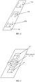
- FIG. 1 illustrates a schematic diagram of an antenna in the related art.
- the antenna implemented as an LCP antenna as an example.
- the arrangement on the LCP antenna 101 is spatially compact; therefore, the arrangement of the antenna units is also compact, distances between the antenna units are small.
- FIG. 2 illustrates a theoretical schematic diagram of electromagnetic coupling produced between two antennas in the related art.
- the distance between the antenna 102 and the antenna 103 is small, and therefore, strong electromagnetic coupling will be produced.
- electromagnetic coupling is produced between the antenna 02 and the antenna 103, there is a current between the antenna 102 and the antenna 103 due to that the antenna 102 and the antenna 103 are both in a live work state.
- mutual inductance may be easily produced between the antenna units due to that the currents in the antenna units are not constant in the work state.
- a surface wave current may be produced due to mutual interference between signals emitted by the antenna 102 and the antenna 103 respectively.
- the surface wave current further affects the normal operation of the antenna 102 and the antenna 103.
- FIG. 3 illustrates a schematic diagram of an antenna 300 according to an exemplary embodiment of the present invention.
- the antenna 300 includes: a first antenna unit 310 and a second antenna unit 320 arranged adjacently.
- the first antenna unit 310 includes a first antenna branch 311 and a first parasitic branch 312, and the second antenna unit 320 includes a second antenna branch 321.
- the first parasitic branch 312 is positioned between the first antenna branch 311 and the second antenna branch 321, and the first parasitic branch 312 is L-shaped.
- the first parasitic branch 312 includes a first branch segment 313 and a second branch segment 314. A first end of the first branch segment 313 is in contact to a ground region, a second end of the first branch segment 313 is joined to a first end of the second branch segment 314, and a second end of the second branch segment 314 points towards the second antenna branch 321.
- first branch segment 313 and the second branch segment 314 may be implemented as a branch entirety pointing towards two directions, or may be implemented as two discrete branch segments joined to each other.
- the first parasitic branch 312 may be composed by the first branch segment 313 and the second branch segment 314 only, or may be composed by the first branch segment 313, the second branch segment 314, and another branch segment.
- the another branch segment is joined to the second branch segment 314.
- both the first antenna branch 311 and the second antenna branch 321 are L-shaped, and the first antenna branch 311 and the second antenna branch 321 run opposite to each other. That is to say, the L shape of the first antenna branch 311 is oriented opposite to that of the second antenna branch 321, and the L shape of the second antenna branch 321 is oriented opposite to that of the first antenna branch 311.
- a frequency band realized by the first antenna unit 310 and a frequency band realized by the second antenna unit 320 are identical; or the frequency band realized by the first antenna unit 310 and the frequency band realized by the second antenna unit 320 contain a same frequency band; or the frequency band realized by the first antenna unit 310 and the frequency band realized by the second antenna unit 320 contain respective frequency bands have a frequency difference between each other that is smaller than a required frequency difference.
- the first parasitic branch 312 is implemented as a part of the first antenna unit 310. Therefore, specific resonance may be formed by a specific wavelength in a specific environment, so that the first parasitic branch 312 may radiate in a specific frequency band to realize signal transceiving.
- first antenna unit 310 and the second antenna unit 320 arranged on an industrial liquid crystal polymer (LCP) material as an example. That is to say, the first antenna unit 310 and the second antenna unit 320 are arranged on an LCP board.
- LCP liquid crystal polymer
- the first antenna unit 310 and the second antenna unit 320 may also be arranged on a terminal middle-frame by means of laser direct structuring (LDS); or the first antenna unit 310 and the second antenna unit 320 may be arranged on a flexible printed circuit (FPC) board or a modified polyimide (MPI) board.
- LDS laser direct structuring
- FPC flexible printed circuit
- MPI modified polyimide
- the ground region is covered with a conductive material; or the ground region is made of a conductive material.
- the operation principle of the antenna provided in embodiments of the present invention is elaborated.
- the first antenna unit 310 and the second antenna unit 320 are arranged on an LCP board. Since multiple antenna units may be implemented on the LCP board, and the multiple antenna units are closely adjacent to one another, when a frequency band of the first antenna unit 310 and a frequency band of the second antenna unit 320 are identical, or contain a same frequency band, or contain respective frequencies close to each other, surface waves produced by the first antenna unit 310 and the second antenna unit 320 have an influence on the radio-frequency operation of the two antenna units.
- the first antenna unit 310 and the second antenna unit 320 may be connected to the other terminal components, so as to ensure that the first antenna unit 310 and the second antenna unit 320 can be powered on normally.
- the first parasitic branch 312 in the first antenna unit 310 is arranged between the first antenna branch 311 and the second antenna branch 321.
- the first parasitic branch 312 is L-shaped, where the L shape is composed by the first branch segment 313 and the second branch segment 314.
- the first branch segment 313 is grounded, and the second branch segment 314 points towards the second antenna branch 321.
- the first antenna branch 311 and the second antenna branch 321 excite the first parasitic branch 312 to generate a reverse current, to counteract the surface waves so as to reduce the isolation degree.
- each of the antenna units is decomposed into an antenna branch and a parasitic branch, and the parasitic branch is configured to be L-shaped and placed between two immediate antenna branches.
- the two antenna branches excite the parasitic branch to generate a reverse current, so as to counteract surface waves, reduce electromagnetic coupling between antenna units, reduce the isolation degree between the antenna units, and improve the accuracy of operation of the antenna units.
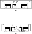
- the second antenna unit 320 includes the second antenna branch 321 and the second parasitic branch 322. As illustrated in FIG. 4 , the second parasitic branch 322 is positioned between the first parasitic branch 312 and the second antenna branch 321.
- the second parasitic branch 322 is L-shaped, and the second parasitic branch 322 includes a third branch segment 323 and a fourth branch segment 324.
- a first end of the third branch segment 323 is in contact to the ground region, a second end of the third branch segment 323 is joined to a first end of the fourth branch segment 324, and a second end of the fourth branch segment 324 points towards the first antenna branch 311.
- the second parasitic branch 322 is L-shaped. That is to say, the second parasitic branch 322 may be composed by the third branch segment 323 and the fourth branch segment 324, or may be composed by the third branch segment 323, the fourth branch segment 324 and another branch segment. The another branch segment is joined to the fourth branch segment 324.
- the operation principle of the antenna provided in embodiments of the present invention is elaborated as follows.
- the first antenna unit 310 and the second antenna unit 320 are arranged on an LCP board.
- the first parasitic branch 312 in the first antenna unit 310 and the second parasitic branch 322 in the second antenna unit 320 are arranged between the first antenna branch 311 and the second antenna branch 321, and the first parasitic branch 312 is arranged between the first antenna branch 311 and the second parasitic branch 322.
- the second parasitic branch 322 is arranged between the first parasitic branch 312 and the second antenna branch 321.
- the first parasitic branch 312 is L-shaped, where the L shape is composed by the first branch segment 313 and the second branch segment 314.
- the first branch segment 313 is grounded, and the second branch segment 314 points towards the second antenna branch 321.
- the second parasitic branch 322 is L-shaped, where the L shape is composed by the third branch segment 323 and the fourth branch segment 324.
- the third branch segment 323 is grounded, and the fourth branch segment 324 points towards the first antenna branch 311.
- the first antenna branch 311 and the second antenna branch 321 excite the first parasitic branch 312 and the second parasitic branch 322 to generate a reverse current, to counteract the surface waves so as to reduce the isolation degree.
- each of the antenna units is decomposed into an antenna branch and a parasitic branch, and the parasitic branch is configured to be L-shaped and placed between two immediate antenna branches.
- the two antenna branches excite the parasitic branch to generate a reverse current, so as to counteract surface waves, reduce electromagnetic coupling between antenna units, reduce the isolation degree between the antenna units, and improve the accuracy of operation of the antenna units.
- the antenna 300 further includes a third antenna unit.
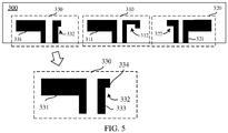
- FIG. 5 illustrates a structural schematic diagram of the arrangement of a first antenna unit, a second antenna unit and a third antenna unit in an exemplary embodiment of the present invention.
- the antenna 300 includes the first antenna unit 310 and the second antenna unit 320.
- the antenna 300 further includes a third antenna unit 330.
- the first antenna unit 310, the second antenna unit 320 and the third antenna unit 330 are arranged in a line in the antenna 300.
- the first antenna unit 310 is positioned between the third antenna unit 330 and the second antenna unit 320.
- the third antenna unit 330 includes a third antenna branch 331 and a third parasitic branch 332.
- the third parasitic branch 332 is positioned between the third antenna branch 331 and the first antenna branch 311.
- the third parasitic branch 332 is L-shaped, and the third parasitic branch 332 includes a fifth branch segment 333 and a sixth branch segment 334.
- a first end of the fifth branch segment 333 is in contact to the ground region
- a second end of the fifth branch segment 333 is in contact to a first end of the sixth branch segment 334
- a second end of the sixth branch segment 334 points towards the first antenna branch 311.
- the third parasitic branch 332 may be composed by the fifth branch segment 333 and the sixth branch segment 334, or may be composed by the fifth branch segment 333, the sixth branch segment 334 and another branch segment.
- the another branch segment is joined to the sixth branch segment 334.
- the first antenna branch 311, the second antenna branch 321 and the third antenna branch 331 are all L-shaped.
- the first antenna branch 311 and the second antenna branch 321 run opposite to each other, and the third antenna branch 311 and the first antenna branch 331 run identically to each other. That is to say, the L shape of the first antenna branch 311 is oriented opposite to that of the second antenna branch 321, the L shape of the second antenna branch 321 is oriented opposite to that of the first antenna branch 311, and the L shape of the third antenna branch 331 is oriented opposite to that of the first antenna branch 311.
- a frequency band of the first antenna unit 310 and a frequency band of the third antenna unit 330 are identical; or the frequency band of the first antenna unit 310 and the frequency band of the third antenna unit 330 contain a same frequency band; or the frequency band of the first antenna unit 310 and the frequency band of the third antenna unit 330 contain respective frequency bands having a frequency difference between each other that is smaller than a required frequency difference.
- the third parasitic branch 332 is implemented as a part of the third antenna unit 330. Therefore, specific resonance may be formed by a specific wavelength in a specific environment, so that the third parasitic branch 332 may radiate in a specific frequency band to implement signal transceiving.
- first antenna unit 310, the second antenna unit 320 and the third antenna unit 330 arranged on an industrial liquid crystal polymer (LCP) material as an example. That is to say, the first antenna unit 310, the second antenna unit 320 and the third antenna unit 330 are arranged on an LCP board.
- LCP liquid crystal polymer
- the first antenna unit 310, the second antenna unit 320 and the third antenna unit 330 may also be arranged on a terminal middle-frame by means of LDS; or the first antenna unit 310, the second antenna unit 320 and the third antenna unit 330 may be arranged on an FPC board or an MPI board.
- the arrangement of the first antenna unit 310, the second antenna unit 320 and the third antenna unit 330 is not limited in embodiments of the present invention.
- the ground region is covered with a conductive material; or the ground region is made of a conductive material.
- the operation principle of the antenna provided in embodiments of the present invention is elaborated as follows.
- the first antenna unit 310 and the third antenna unit 330 are arranged on an LCP board. Since multiple antenna units may be implemented on the LCP board, and the multiple antenna units are closely adjacent to one another, when the frequency band of the first antenna unit 310 and the frequency band of the third antenna unit 330 are identical, or contain a same frequency band, or contain respective frequencies close to each other, surface waves produced between the first antenna unit 310 and the third antenna unit 330 have an influence on the radio-frequency operation of the two antenna units.
- the first antenna unit 310 and the third antenna unit 330 may be connected to the other terminal components, so as to ensure that the first antenna unit 310 and the third antenna unit 330 can be powered on normally.
- the third parasitic branch 332 in the third antenna unit 330 is arranged between the first antenna branch 311 and the third antenna branch 331, and the third parasitic branch 332 is L-shaped, where the L shape is composed by the fifth branch segment 333 and the sixth branch segment 334.
- the fifth branch segment 333 is grounded, and the sixth branch segment 334 points towards the first antenna branch 311.
- each of the antenna units is decomposed into an antenna branch and a parasitic branch, and the parasitic branch is configured to be L-shaped and placed between two immediate antenna branches.
- the two antenna branches excite the parasitic branch to generate a reverse current, so as to counteract surface waves, reduce electromagnetic coupling between antenna units, reduce the degree of isolation between the antenna units, and improve the accuracy of operation of the antenna units.
- each antenna unit may be correspondingly provided with an antenna branch and a parasitic branch. It is also feasible that some of the antenna units are provided with an antenna branch and a parasitic branch, and the other of the antenna units include an antenna branch only. Optionally, there is a parasitic branch between two immediate antenna branches to excite a reverse current and counteract surface waves.
- the first antenna unit 310 is positioned at the left side of the second antenna unit 320
- the third antenna unit 330 is positioned at the left side of the first antenna unit 310.
- the further antenna unit may continue to be arranged at the left side of the third antenna unit 330 in the same manner as the third antenna branch 331 and the third parasitic branch 332 in the third antenna unit 330 are arranged.
- the fourth antenna unit may be arranged at the right side of the second antenna unit 320.
- the fourth antenna unit is arranged at the right side of the second antenna unit 320.
- the antenna 300 includes the first antenna unit 310, the second antenna unit 320, the third antenna unit 330 and the fourth antenna unit 340 described above.
- the first antenna unit 310, the second antenna unit 320, the third antenna unit 330 and the fourth antenna unit are arranged in a line in the antenna 300.
- the fourth antenna unit 340 includes a fourth antenna branch 341 and a fourth parasitic branch 342.
- the fourth parasitic branch 342 is positioned between the second antenna branch 321 and the fourth antenna branch 341.
- the fourth parasitic branch 342 is L-shaped, and the fourth parasitic branch 342 includes a seventh branch segment 343 and an eighth branch segment 344. A first end of the seventh branch segment 343 is in contact to the ground region, a second end of the seventh branch segment 343 is in contact to a first end of the eighth branch segment 344, and a second end of the eighth branch segment 344 points towards the second antenna branch 321.
- the first antenna branch 311, the second antenna branch 321 and the third antenna branch 331 are all L-shaped.
- the first antenna branch 311 and the second antenna branch 321 run opposite to each other, and the third antenna branch 311 and the first antenna branch 331 run identically to each other. That is to say, the L shape of the first antenna branch 311 is oriented opposite to that of the second antenna branch 321, the L shape of the second antenna branch 321 is oriented opposite to that of the first antenna branch 311, and the L shape of the third antenna branch 331 is oriented opposite to that of the first antenna branch 311.
- the fourth antenna unit 340 is positioned at the right side of the second antenna unit 320.
- the further antenna unit may continue to be arranged at the right side of the fourth antenna unit 340 in the same manner as the fourth antenna branch 341 and the fourth parasitic branch 342 in the fourth antenna unit 340 are arranged.
- the second antenna unit 320 and the fourth antenna unit 340 are arranged on an LCP board. Since multiple antenna units may be implemented on the LCP board, and the multiple antenna units are closely adjacent to one another, when the frequency band of the second antenna unit 320 and the frequency band of the fourth antenna unit 340 are identical, or contain a same frequency band, or contain close frequencies, surface waves produced between the second antenna unit 320 and the fourth antenna unit 340 have an influence on the radio-frequency operation of the two antenna units.
- the second antenna unit 320 and the fourth antenna unit 340 may be connected to the other terminal components, so as to ensure that the second antenna unit 320 and the fourth antenna unit 340 can be powered on normally.
- the fourth parasitic branch 342 in the fourth antenna unit 340 is arranged between the second antenna branch 321 and the fourth antenna branch 341.
- the fourth parasitic branch 342 is L-shaped, where the L shape is composed by the seventh branch segment 343 and the eighth branch segment 344.
- the seventh branch segment 343 is grounded, and the eighth branch segment 344 points towards the second antenna branch 321.
- the second antenna branch 321 and the fourth antenna branch 341 excite the fourth parasitic branch 342 to generate a reverse current, to counteract the surface waves so as to reduce the isolation degree.
- each of the antenna units is decomposed into an antenna branch and a parasitic branch, and the parasitic branch is configured to be L-shaped and placed between two immediate antenna branches.
- the two antenna branches excite the parasitic branch to generate a reverse current, so as to counteract surface waves, reduce electromagnetic coupling between antenna units, reduce the isolation degree between the antenna units, and improve the accuracy of operation of the antenna units.
- a terminal middle-frame is also provided in embodiments of the present invention.
- the terminal middle-frame is installed with at least one of the antennas in the embodiments of the present invention above.
- a terminal is also provided in embodiments of the present invention.
- the terminal is installed with at least one of the antennas in the embodiments of the present invention above.
- the program may be stored in a computer-readable storage medium which may be a read-only memory, a magnetic disk, an optical disc or the like.
- the terms “installed,” “connected,” “coupled,” “fixed” and the like shall be understood broadly, and can be either a fixed connection or a detachable connection, or integrated, unless otherwise explicitly defined. These terms can refer to mechanical or electrical connections, or both. Such connections can be direct connections or indirect connections through an intermediate medium. These terms can also refer to the internal connections or the interactions between elements. The specific meanings of the above terms in the present invention can be understood by those of ordinary skill in the art on a case-by-case basis.
- the terms “one embodiment,” “some embodiments,” “example,” “specific example,” or “some examples,” and the like can indicate a specific feature described in connection with the embodiment or example, a structure, a material or feature included in at least one embodiment or example.
- the schematic representation of the above terms is not necessarily directed to the same embodiment or example.
- control and/or interface software or app can be provided in a form of a non-transitory computer-readable storage medium having instructions stored thereon is further provided.
- the non-transitory computer-readable storage medium can be a ROM, a CD-ROM, a magnetic tape, a floppy disk, optical data storage equipment, a flash drive such as a USB drive or an SD card, and the like.
- Implementations of the subject matter and the operations described in this disclosure can be implemented in digital electronic circuitry, or in computer software, firmware, or hardware, including the structures disclosed herein and their structural equivalents, or in combinations of one or more of them. Implementations of the subject matter described in this disclosure can be implemented as one or more computer programs, i.e., one or more portions of computer program instructions, encoded on one or more computer storage medium for execution by, or to control the operation of, data processing apparatus.
- the program instructions can be encoded on an artificially-generated propagated signal, e.g., a machine-generated electrical, optical, or electromagnetic signal, which is generated to encode information for transmission to suitable receiver apparatus for execution by a data processing apparatus.
- an artificially-generated propagated signal e.g., a machine-generated electrical, optical, or electromagnetic signal, which is generated to encode information for transmission to suitable receiver apparatus for execution by a data processing apparatus.
- a computer storage medium can be, or be included in, a computer-readable storage device, a computer-readable storage substrate, a random or serial access memory array or device, or a combination of one or more of them.
- a computer storage medium is not a propagated signal
- a computer storage medium can be a source or destination of computer program instructions encoded in an artificially-generated propagated signal.
- the computer storage medium can also be, or be included in, one or more separate components or media (e.g., multiple CDs, disks, drives, or other storage devices). Accordingly, the computer storage medium can be tangible.
- the operations described in this disclosure can be implemented as operations performed by a data processing apparatus on data stored on one or more computer-readable storage devices or received from other sources.
- the devices in this disclosure can include special purpose logic circuitry, e.g., an FPGA (field-programmable gate array), or an ASIC (application-specific integrated circuit).
- the device can also include, in addition to hardware, code that creates an execution environment for the computer program in question, e.g., code that constitutes processor firmware, a protocol stack, a database management system, an operating system, a cross-platform runtime environment, a virtual machine, or a combination of one or more of them.
- the devices and execution environment can realize various different computing model infrastructures, such as web services, distributed computing, and grid computing infrastructures.
- a computer program (also known as a program, software, software application, app, script, or code) can be written in any form of programming language, including compiled or interpreted languages, declarative or procedural languages, and it can be deployed in any form, including as a stand-alone program or as a portion, component, subroutine, object, or other portion suitable for use in a computing environment.
- a computer program can, but need not, correspond to a file in a file system.
- a program can be stored in a portion of a file that holds other programs or data (e.g., one or more scripts stored in a markup language document), in a single file dedicated to the program in question, or in multiple coordinated files (e.g., files that store one or more portions, sub-programs, or portions of code).
- a computer program can be deployed to be executed on one computer or on multiple computers that are located at one site or distributed across multiple sites and interconnected by a communication network.
- the processes and logic flows described in this disclosure can be performed by one or more programmable processors executing one or more computer programs to perform actions by operating on input data and generating output.
- the processes and logic flows can also be performed by, and apparatus can also be implemented as, special purpose logic circuitry, e.g., an FPGA, or an ASIC.
- processors or processing circuits suitable for the execution of a computer program include, by way of example, both general and special purpose microprocessors, and any one or more processors of any kind of digital computer.
- a processor will receive instructions and data from a read-only memory, or a random-access memory, or both.
- Elements of a computer can include a processor configured to perform actions in accordance with instructions and one or more memory devices for storing instructions and data.
- a computer will also include, or be operatively coupled to receive data from or transfer data to, or both, one or more mass storage devices for storing data, e.g., magnetic, magneto-optical disks, or optical disks.
- mass storage devices for storing data
- a computer need not have such devices.
- a computer can be embedded in another device, e.g., a mobile telephone, a personal digital assistant (PDA), a mobile audio or video player, a game console, a Global Positioning System (GPS) receiver, or a portable storage device (e.g., a universal serial bus (USB) flash drive), to name just a few.
- PDA personal digital assistant
- GPS Global Positioning System
- USB universal serial bus
- Devices suitable for storing computer program instructions and data include all forms of non-volatile memory, media and memory devices, including by way of example semiconductor memory devices, e.g., EPROM, EEPROM, and flash memory devices; magnetic disks, e.g., internal hard disks or removable disks; magneto-optical disks; and CD-ROM and DVD-ROM disks.
- semiconductor memory devices e.g., EPROM, EEPROM, and flash memory devices
- magnetic disks e.g., internal hard disks or removable disks
- magneto-optical disks e.g., CD-ROM and DVD-ROM disks.
- the processor and the memory can be supplemented by, or incorporated in, special purpose logic circuitry.
- implementations of the subject matter described in this specification can be implemented with a computer and/or a display device, e.g., a VR/AR device, a head-mount display (HMD) device, a head-up display (HUD) device, smart eyewear (e.g., glasses), a CRT (cathode-ray tube), LCD (liquid-crystal display), OLED (organic light emitting diode), or any other monitor for displaying information to the user and a keyboard, a pointing device, e.g., a mouse, trackball, etc., or a touch screen, touch pad, etc., by which the user can provide input to the computer.
- a display device e.g., a VR/AR device, a head-mount display (HMD) device, a head-up display (HUD) device, smart eyewear (e.g., glasses), a CRT (cathode-ray tube), LCD (liquid-crystal display), OLED (organic light emitting dio
- Implementations of the subject matter described in this specification can be implemented in a computing system that includes a back-end component, e.g., as a data server, or that includes a middleware component, e.g., an application server, or that includes a front-end component, e.g., a client computer having a graphical user interface or a Web browser through which a user can interact with an implementation of the subject matter described in this specification, or any combination of one or more such back-end, middleware, or front-end components.
- a back-end component e.g., as a data server
- a middleware component e.g., an application server
- a front-end component e.g., a client computer having a graphical user interface or a Web browser through which a user can interact with an implementation of the subject matter described in this specification, or any combination of one or more such back-end, middleware, or front-end components.
- the components of the system can be interconnected by any form or medium of digital data communication, e.g., a communication network.
- communication networks include a local area network ("LAN”) and a wide area network (“WAN”), an inter-network (e.g., the Internet), and peer-to-peer networks (e.g., ad hoc peer-to-peer networks).
- LAN local area network
- WAN wide area network
- Internet inter-network
- peer-to-peer networks e.g., ad hoc peer-to-peer networks.
- first and second are used for descriptive purposes only and are not to be construed as indicating or implying a relative importance or implicitly indicating the number of technical features indicated.
- elements referred to as “first” and “second” may include one or more of the features either explicitly or implicitly.
- a plurality indicates two or more unless specifically defined otherwise.
- a first element being "on” a second element may indicate direct contact between the first and second elements, without contact, or indirect geometrical relationship through one or more intermediate media or layers, unless otherwise explicitly stated and defined.
- a first element being "under,” “underneath” or “beneath” a second element may indicate direct contact between the first and second elements, without contact, or indirect geometrical relationship through one or more intermediate media or layers, unless otherwise explicitly stated and defined.
- the terms “some embodiments,” “example,” or “some examples,” and the like may indicate a specific feature described in connection with the embodiment or example, a structure, a material or feature included in at least one embodiment or example.
- the schematic representation of the above terms is not necessarily directed to the same embodiment or example.
- the terms “installed,” “connected,” “coupled,” “fixed” and the like shall be understood broadly, and can be either a fixed connection or a detachable connection, or integrated, unless otherwise explicitly defined. These terms can refer to mechanical or electrical connections, or both. Such connections can be direct connections or indirect connections through an intermediate medium. These terms can also refer to the internal connections or the interactions between elements. The specific meanings of the above terms in the present invention can be understood by those of ordinary skill in the art on a case-by-case basis.
- the terms “one embodiment,” “some embodiments,” “example,” “specific example,” or “some examples,” and the like can indicate a specific feature described in connection with the embodiment or example, a structure, a material or feature included in at least one embodiment or example.
- the schematic representation of the above terms is not necessarily directed to the same embodiment or example.
- first and second are used for descriptive purposes only and are not to be construed as indicating or implying a relative importance or implicitly indicating the number of technical features indicated.
- elements referred to as “first” and “second” may include one or more of the features either explicitly or implicitly.
- a plurality indicates two or more unless specifically defined otherwise.
- a first element being "on” a second element may indicate direct contact between the first and second elements, without contact, or indirect geometrical relationship through one or more intermediate media or layers, unless otherwise explicitly stated and defined.
- a first element being "under,” “underneath” or “beneath” a second element may indicate direct contact between the first and second elements, without contact, or indirect geometrical relationship through one or more intermediate media or layers, unless otherwise explicitly stated and defined.
Landscapes
- Engineering & Computer Science (AREA)
- Computer Networks & Wireless Communication (AREA)
- Support Of Aerials (AREA)
- Variable-Direction Aerials And Aerial Arrays (AREA)
- Details Of Aerials (AREA)
Abstract
Description
- The present invention relates to the field of communication hardware, and particularly to an antenna, a terminal middle-frame, and a terminal.
- As diversification of functions of mobile terminals, the requirement on the number and functions of antennas inside the mobile terminals have increased gradually.
- In order to adapt to both the communication and function requirements of the mobile terminal, and the spatially compact arrangement inside the mobile terminal, antennas inside the mobile terminal are mostly made of an industrial liquid crystal polymer (LCP). In order to adapt to the communication requirements of the mobile terminal, multiple antenna units may also be integrated on the LCP antenna inside the mobile terminal.
- However, the integration of multiple antenna units on the LCP antenna may easily lead to electromagnetic coupling between the antenna units, and thus cause isolation between two immediate antenna units, affecting the normal operation of the antenna.
- In the present invention, an antenna, a terminal middle-frame, and a terminal are provided, which can solve the problem that the integration of multiple antenna units on an LCP antenna easily lead to electromagnetic coupling between the antenna units, which further causes isolation between two immediate antenna units and affects the normal operation of the antenna. The technical solutions are as follows.
- On one aspect, an antenna is provided. The antenna includes: a first antenna unit and a second antenna unit arranged adjacently.
- The first antenna unit includes a first antenna branch and a first parasitic branch, and the second antenna unit includes a second antenna branch; the first parasitic branch is positioned between the first antenna branch and the second antenna branch; the first parasitic branch is L-shaped, and the first parasitic branch includes a first branch segment and a second branch segment; and a first end of the first branch segment is in contact to a ground region, a second end of the first branch segment is joined to a first end of the second branch segment, and a second end of the second branch segment points towards the second antenna branch.
- In an optional embodiment, the second antenna unit further includes a second parasitic branch, and the second parasitic branch is positioned between the first parasitic branch and the second antenna branch; the second parasitic branch is L-shaped, and the second parasitic branch includes a third branch segment and a fourth branch segment; and a first end of the third branch segment is in contact to the ground region, a second end of the third branch segment is joined to a first end of the fourth branch segment, and a second end of the fourth branch segment points towards the first antenna branch.
- In an optional embodiment, the first antenna branch and the second antenna branch are L-shaped; and the first antenna branch and the second antenna branch run opposite to each other.
- In an optional embodiment, a frequency band realized by the first antenna unit and a frequency band realized by the second antenna unit are identical; or the frequency band realized by the first antenna unit and the frequency band realized by the second antenna unit contain a same frequency band; or the frequency band realized by the first antenna unit and the frequency band realized by the second antenna unit contain respective frequency bands having a frequency difference between each other that is smaller than a required frequency difference.
- In an optional embodiment, the antenna further includes a third antenna unit, and the first antenna unit is positioned between the third antenna unit and the second antenna unit; the third antenna unit includes a third antenna branch and a third parasitic branch; the third parasitic branch is positioned between the third antenna branch and the first antenna branch; the third parasitic branch is L-shaped, and the third parasitic branch includes a fifth branch segment and a sixth branch segment; and a first end of the fifth branch segment is in contact to the ground region, a second end of the fifth branch segment is joined to a first end of the sixth branch segment, and a second end of the sixth branch segment points towards the first antenna branch.
- In an optional embodiment, the first antenna unit, the second antenna unit and the third antenna unit are arranged in a line in the antenna.
- In an optional embodiment, the first antenna unit and the second antenna unit are arranged on an industrial liquid crystal polymer material.
- In an optional embodiment, the ground region is covered with a conductive material; or the ground region is made of a conductive material.
- On another aspect, a terminal middle-frame is provided. The terminal middle-frame is installed with any antenna as described above.
- On another aspect, a terminal is provided. The terminal is installed with any antenna as described above.
- The technical solution provided in the present invention at least has the following beneficial effects.
- Each of the antenna units is decomposed into an antenna branch and a parasitic branch, and the parasitic branch is configured to be L-shaped and placed between two immediate antenna branches. As such, the two antenna branches excite the parasitic branch to generate a reverse current, so as to counteract surface waves, reduce electromagnetic coupling between antenna units, reduce the isolation degree between the antenna units, and improve the accuracy of operation of the antenna units.
- In order to illustrate the technical solution in embodiments of the present invention more clearly, brief introduction will be made below to the drawings required for the description of the embodiments. Apparently, the drawings in the following description are only some of the embodiments of the present invention, and those of ordinary skill in the art would be able to derive other drawings as well from these drawings without paying any inventive effort.
-
FIG. 1 illustrates a structural schematic diagram of the arrangement of antenna units in the related art. -
FIG. 2 illustrates a theoretical schematic diagram of an electromagnetic coupling phenomenon produced between two antenna units in the related art. -
FIG. 3 illustrates a structural schematic diagram of the arrangement of antenna units according to an exemplary embodiment of the present invention. -
FIG. 4 illustrates a structural schematic diagram of the arrangement of antenna units according to another exemplary embodiment of the present invention. -
FIG. 5 illustrates a structural schematic diagram of the arrangement of a first antenna unit, a second antenna unit and a third antenna unit in an exemplary embodiment of the present invention. -
FIG. 6 illustrates a structural schematic diagram of the arrangement of four antenna units according to an exemplary embodiment of the present invention. - In order to make the purpose, technical solutions and advantages of the present invention more clear, embodiments of the present invention will be further described in more detail in conjunction with the accompanying drawings.
- First of all, nouns involved in embodiments of the present invention are briefly introduced.
- Electromagnetic coupling: is also referred to as mutual inductance coupling, and is a phenomenon that, due to the existence of mutual inductance between two circuits, a current change in one of the circuits has an influence on the other of the circuits via the mutual inductance. When there is tight cooperation and mutual influence between an input and output of two or more circuit elements or electric networks, energy will be transmitted from one side to the other side through interaction. When two set of antennas close to each other are operating simultaneously, the two set of antennas will also have an influence on each other due to the mutual inductance phenomenon, that is, producing electromagnetic interference to each other.
- Antenna isolation degree: is used to quantitatively characterize the strength of electromagnetic coupling between the antennas, is defined as the ratio of the transmission power of one antenna to the receiving power of the other antenna, and is in unit of dB. When the antenna isolation degree is low, it means that the two antennas may easily produce electromagnetic interference to each other, and have an influence on the transmission efficiency of each other. Generally, in an existing communication terminal, it should be ensured that the isolation degree between two antennas in a same terminal is smaller than or equal to -15dB.
-
FIG. 1 illustrates a schematic diagram of an antenna in the related art. Referring toFIG. 1 , explanation is made with the antenna implemented as an LCP antenna as an example. As illustrated inFIG. 1 , there is anantenna unit 102, anantenna unit 103 and anantenna unit 104 on theLCP antenna 101. Optionally, the arrangement on theLCP antenna 101 is spatially compact; therefore, the arrangement of the antenna units is also compact, distances between the antenna units are small. -
FIG. 2 illustrates a theoretical schematic diagram of electromagnetic coupling produced between two antennas in the related art. Referring toFIG. 2 , the distance between theantenna 102 and theantenna 103 is small, and therefore, strong electromagnetic coupling will be produced. When electromagnetic coupling is produced between the antenna 02 and theantenna 103, there is a current between theantenna 102 and theantenna 103 due to that theantenna 102 and theantenna 103 are both in a live work state. Exemplarily, when both theantenna 102 and theantenna 103 are in the live work state, mutual inductance may be easily produced between the antenna units due to that the currents in the antenna units are not constant in the work state. At this time, a surface wave current may be produced due to mutual interference between signals emitted by theantenna 102 and theantenna 103 respectively. The surface wave current further affects the normal operation of theantenna 102 and theantenna 103. -
FIG. 3 illustrates a schematic diagram of anantenna 300 according to an exemplary embodiment of the present invention. Theantenna 300 includes: afirst antenna unit 310 and asecond antenna unit 320 arranged adjacently. - The
first antenna unit 310 includes afirst antenna branch 311 and a firstparasitic branch 312, and thesecond antenna unit 320 includes asecond antenna branch 321. The firstparasitic branch 312 is positioned between thefirst antenna branch 311 and thesecond antenna branch 321, and the firstparasitic branch 312 is L-shaped. The firstparasitic branch 312 includes afirst branch segment 313 and asecond branch segment 314. A first end of thefirst branch segment 313 is in contact to a ground region, a second end of thefirst branch segment 313 is joined to a first end of thesecond branch segment 314, and a second end of thesecond branch segment 314 points towards thesecond antenna branch 321. - Optionally, the
first branch segment 313 and thesecond branch segment 314 may be implemented as a branch entirety pointing towards two directions, or may be implemented as two discrete branch segments joined to each other. - Optionally, since the first
parasitic branch 312 is L-shaped, the firstparasitic branch 312 may be composed by thefirst branch segment 313 and thesecond branch segment 314 only, or may be composed by thefirst branch segment 313, thesecond branch segment 314, and another branch segment. The another branch segment is joined to thesecond branch segment 314. - Optionally, as illustrated in
FIG. 3 , both thefirst antenna branch 311 and thesecond antenna branch 321 are L-shaped, and thefirst antenna branch 311 and thesecond antenna branch 321 run opposite to each other. That is to say, the L shape of thefirst antenna branch 311 is oriented opposite to that of thesecond antenna branch 321, and the L shape of thesecond antenna branch 321 is oriented opposite to that of thefirst antenna branch 311. - Optionally, a frequency band realized by the
first antenna unit 310 and a frequency band realized by thesecond antenna unit 320 are identical; or the frequency band realized by thefirst antenna unit 310 and the frequency band realized by thesecond antenna unit 320 contain a same frequency band; or the frequency band realized by thefirst antenna unit 310 and the frequency band realized by thesecond antenna unit 320 contain respective frequency bands have a frequency difference between each other that is smaller than a required frequency difference. - Optionally, the first
parasitic branch 312 is implemented as a part of thefirst antenna unit 310. Therefore, specific resonance may be formed by a specific wavelength in a specific environment, so that the firstparasitic branch 312 may radiate in a specific frequency band to realize signal transceiving. - Optionally, in embodiments of the present invention, explanation is made with the
first antenna unit 310 and thesecond antenna unit 320 arranged on an industrial liquid crystal polymer (LCP) material as an example. That is to say, thefirst antenna unit 310 and thesecond antenna unit 320 are arranged on an LCP board. - Optionally, the
first antenna unit 310 and thesecond antenna unit 320 may also be arranged on a terminal middle-frame by means of laser direct structuring (LDS); or thefirst antenna unit 310 and thesecond antenna unit 320 may be arranged on a flexible printed circuit (FPC) board or a modified polyimide (MPI) board. The arrangement of thefirst antenna unit 310 and thesecond antenna unit 320 are not specified in embodiments of the present invention. - Optionally, the ground region is covered with a conductive material; or the ground region is made of a conductive material.
- With the
first antenna unit 310 and thesecond antenna unit 320 arranged on the LCP antenna as an example, the operation principle of the antenna provided in embodiments of the present invention is elaborated. - The
first antenna unit 310 and thesecond antenna unit 320 are arranged on an LCP board. Since multiple antenna units may be implemented on the LCP board, and the multiple antenna units are closely adjacent to one another, when a frequency band of thefirst antenna unit 310 and a frequency band of thesecond antenna unit 320 are identical, or contain a same frequency band, or contain respective frequencies close to each other, surface waves produced by thefirst antenna unit 310 and thesecond antenna unit 320 have an influence on the radio-frequency operation of the two antenna units. Optionally, thefirst antenna unit 310 and thesecond antenna unit 320 may be connected to the other terminal components, so as to ensure that thefirst antenna unit 310 and thesecond antenna unit 320 can be powered on normally. The firstparasitic branch 312 in thefirst antenna unit 310 is arranged between thefirst antenna branch 311 and thesecond antenna branch 321. The firstparasitic branch 312 is L-shaped, where the L shape is composed by thefirst branch segment 313 and thesecond branch segment 314. Thefirst branch segment 313 is grounded, and thesecond branch segment 314 points towards thesecond antenna branch 321. When surface waves are produced between thefirst antenna branch 311 and thesecond antenna branch 321 due to signal interference, thefirst antenna branch 311 and thesecond antenna branch 321 excite the firstparasitic branch 312 to generate a reverse current, to counteract the surface waves so as to reduce the isolation degree. - In summary, in the antenna provided in embodiments of the present invention, each of the antenna units is decomposed into an antenna branch and a parasitic branch, and the parasitic branch is configured to be L-shaped and placed between two immediate antenna branches. As such, the two antenna branches excite the parasitic branch to generate a reverse current, so as to counteract surface waves, reduce electromagnetic coupling between antenna units, reduce the isolation degree between the antenna units, and improve the accuracy of operation of the antenna units.
- In an optional embodiment, referring to
FIG. 4 , thesecond antenna unit 320 includes thesecond antenna branch 321 and the secondparasitic branch 322. As illustrated inFIG. 4 , the secondparasitic branch 322 is positioned between the firstparasitic branch 312 and thesecond antenna branch 321. - The second
parasitic branch 322 is L-shaped, and the secondparasitic branch 322 includes athird branch segment 323 and afourth branch segment 324. A first end of thethird branch segment 323 is in contact to the ground region, a second end of thethird branch segment 323 is joined to a first end of thefourth branch segment 324, and a second end of thefourth branch segment 324 points towards thefirst antenna branch 311. - Optionally, the second
parasitic branch 322 is L-shaped. That is to say, the secondparasitic branch 322 may be composed by thethird branch segment 323 and thefourth branch segment 324, or may be composed by thethird branch segment 323, thefourth branch segment 324 and another branch segment. The another branch segment is joined to thefourth branch segment 324. - With the
first antenna unit 310 and thesecond antenna unit 320 arranged on the LCP antenna as an example, the operation principle of the antenna provided in embodiments of the present invention is elaborated as follows. - The
first antenna unit 310 and thesecond antenna unit 320 are arranged on an LCP board. The firstparasitic branch 312 in thefirst antenna unit 310 and the secondparasitic branch 322 in thesecond antenna unit 320 are arranged between thefirst antenna branch 311 and thesecond antenna branch 321, and the firstparasitic branch 312 is arranged between thefirst antenna branch 311 and the secondparasitic branch 322. Similarly, the secondparasitic branch 322 is arranged between the firstparasitic branch 312 and thesecond antenna branch 321. The firstparasitic branch 312 is L-shaped, where the L shape is composed by thefirst branch segment 313 and thesecond branch segment 314. Thefirst branch segment 313 is grounded, and thesecond branch segment 314 points towards thesecond antenna branch 321. The secondparasitic branch 322 is L-shaped, where the L shape is composed by thethird branch segment 323 and thefourth branch segment 324. Thethird branch segment 323 is grounded, and thefourth branch segment 324 points towards thefirst antenna branch 311. When surface waves are produced between thefirst antenna branch 311 and thesecond antenna branch 321 due to signal interference, thefirst antenna branch 311 and thesecond antenna branch 321 excite the firstparasitic branch 312 and the secondparasitic branch 322 to generate a reverse current, to counteract the surface waves so as to reduce the isolation degree. - In summary, in the antenna provided in embodiments of the present invention, each of the antenna units is decomposed into an antenna branch and a parasitic branch, and the parasitic branch is configured to be L-shaped and placed between two immediate antenna branches. As such, the two antenna branches excite the parasitic branch to generate a reverse current, so as to counteract surface waves, reduce electromagnetic coupling between antenna units, reduce the isolation degree between the antenna units, and improve the accuracy of operation of the antenna units.
- In an optional embodiment, the
antenna 300 further includes a third antenna unit. Exemplarily, referring toFIG. 5 which illustrates a structural schematic diagram of the arrangement of a first antenna unit, a second antenna unit and a third antenna unit in an exemplary embodiment of the present invention. As illustrated inFIG. 5 , theantenna 300 includes thefirst antenna unit 310 and thesecond antenna unit 320. Theantenna 300 further includes athird antenna unit 330. Thefirst antenna unit 310, thesecond antenna unit 320 and thethird antenna unit 330 are arranged in a line in theantenna 300. - Optionally, as illustrated in
FIG. 5 , thefirst antenna unit 310 is positioned between thethird antenna unit 330 and thesecond antenna unit 320. Thethird antenna unit 330 includes athird antenna branch 331 and a thirdparasitic branch 332. The thirdparasitic branch 332 is positioned between thethird antenna branch 331 and thefirst antenna branch 311. Optionally, the thirdparasitic branch 332 is L-shaped, and the thirdparasitic branch 332 includes afifth branch segment 333 and asixth branch segment 334. A first end of thefifth branch segment 333 is in contact to the ground region, a second end of thefifth branch segment 333 is in contact to a first end of thesixth branch segment 334, and a second end of thesixth branch segment 334 points towards thefirst antenna branch 311. - Optionally, since the third
parasitic branch 332 is L-shaped, the thirdparasitic branch 332 may be composed by thefifth branch segment 333 and thesixth branch segment 334, or may be composed by thefifth branch segment 333, thesixth branch segment 334 and another branch segment. The another branch segment is joined to thesixth branch segment 334. - Optionally, as illustrated in
FIG. 5 , thefirst antenna branch 311, thesecond antenna branch 321 and thethird antenna branch 331 are all L-shaped. Thefirst antenna branch 311 and thesecond antenna branch 321 run opposite to each other, and thethird antenna branch 311 and thefirst antenna branch 331 run identically to each other. That is to say, the L shape of thefirst antenna branch 311 is oriented opposite to that of thesecond antenna branch 321, the L shape of thesecond antenna branch 321 is oriented opposite to that of thefirst antenna branch 311, and the L shape of thethird antenna branch 331 is oriented opposite to that of thefirst antenna branch 311. - Optionally, a frequency band of the
first antenna unit 310 and a frequency band of thethird antenna unit 330 are identical; or the frequency band of thefirst antenna unit 310 and the frequency band of thethird antenna unit 330 contain a same frequency band; or the frequency band of thefirst antenna unit 310 and the frequency band of thethird antenna unit 330 contain respective frequency bands having a frequency difference between each other that is smaller than a required frequency difference. - Optionally, the third
parasitic branch 332 is implemented as a part of thethird antenna unit 330. Therefore, specific resonance may be formed by a specific wavelength in a specific environment, so that the thirdparasitic branch 332 may radiate in a specific frequency band to implement signal transceiving. - Optionally, in embodiments of the present invention, explanation is made with the
first antenna unit 310, thesecond antenna unit 320 and thethird antenna unit 330 arranged on an industrial liquid crystal polymer (LCP) material as an example. That is to say, thefirst antenna unit 310, thesecond antenna unit 320 and thethird antenna unit 330 are arranged on an LCP board. - Optionally, the
first antenna unit 310, thesecond antenna unit 320 and thethird antenna unit 330 may also be arranged on a terminal middle-frame by means of LDS; or thefirst antenna unit 310, thesecond antenna unit 320 and thethird antenna unit 330 may be arranged on an FPC board or an MPI board. The arrangement of thefirst antenna unit 310, thesecond antenna unit 320 and thethird antenna unit 330 is not limited in embodiments of the present invention. - Optionally, the ground region is covered with a conductive material; or the ground region is made of a conductive material.
- With regard to the isolation degree between the
first antenna unit 310 and thethird antenna unit 330, the operation principle of the antenna provided in embodiments of the present invention is elaborated as follows. - The
first antenna unit 310 and thethird antenna unit 330 are arranged on an LCP board. Since multiple antenna units may be implemented on the LCP board, and the multiple antenna units are closely adjacent to one another, when the frequency band of thefirst antenna unit 310 and the frequency band of thethird antenna unit 330 are identical, or contain a same frequency band, or contain respective frequencies close to each other, surface waves produced between thefirst antenna unit 310 and thethird antenna unit 330 have an influence on the radio-frequency operation of the two antenna units. Optionally, thefirst antenna unit 310 and thethird antenna unit 330 may be connected to the other terminal components, so as to ensure that thefirst antenna unit 310 and thethird antenna unit 330 can be powered on normally. The thirdparasitic branch 332 in thethird antenna unit 330 is arranged between thefirst antenna branch 311 and thethird antenna branch 331, and the thirdparasitic branch 332 is L-shaped, where the L shape is composed by thefifth branch segment 333 and thesixth branch segment 334. Thefifth branch segment 333 is grounded, and thesixth branch segment 334 points towards thefirst antenna branch 311. When surface waves are produced between thefirst antenna branch 311 and thethird antenna branch 331 due to signal interference, thefirst antenna branch 311 and thethird antenna branch 331 excite the thirdparasitic branch 332 to generate a reverse current, to counteract the surface waves so as to reduce the isolation degree. - In summary, in the antenna provided in embodiments of the present invention, each of the antenna units is decomposed into an antenna branch and a parasitic branch, and the parasitic branch is configured to be L-shaped and placed between two immediate antenna branches. As such, the two antenna branches excite the parasitic branch to generate a reverse current, so as to counteract surface waves, reduce electromagnetic coupling between antenna units, reduce the degree of isolation between the antenna units, and improve the accuracy of operation of the antenna units.
- It is to be noted that, for the antenna units in the
antenna 300, each antenna unit may be correspondingly provided with an antenna branch and a parasitic branch. It is also feasible that some of the antenna units are provided with an antenna branch and a parasitic branch, and the other of the antenna units include an antenna branch only. Optionally, there is a parasitic branch between two immediate antenna branches to excite a reverse current and counteract surface waves. - Exemplarily, as illustrated in
FIG. 5 , thefirst antenna unit 310 is positioned at the left side of thesecond antenna unit 320, and thethird antenna unit 330 is positioned at the left side of thefirst antenna unit 310. When a further antenna unit needs to be arranged at the left side of thethird antenna unit 330, the further antenna unit may continue to be arranged at the left side of thethird antenna unit 330 in the same manner as thethird antenna branch 331 and the thirdparasitic branch 332 in thethird antenna unit 330 are arranged. - Optionally, there may be a fourth antenna unit arranged at the right side of the
second antenna unit 320. Exemplarily, as illustrated inFIG. 6 , the fourth antenna unit is arranged at the right side of thesecond antenna unit 320. Theantenna 300 includes thefirst antenna unit 310, thesecond antenna unit 320, thethird antenna unit 330 and thefourth antenna unit 340 described above. Thefirst antenna unit 310, thesecond antenna unit 320, thethird antenna unit 330 and the fourth antenna unit are arranged in a line in theantenna 300. - Optionally, as illustrated in
FIG. 6 , thefourth antenna unit 340 includes afourth antenna branch 341 and a fourthparasitic branch 342. The fourthparasitic branch 342 is positioned between thesecond antenna branch 321 and thefourth antenna branch 341. Optionally, the fourthparasitic branch 342 is L-shaped, and the fourthparasitic branch 342 includes aseventh branch segment 343 and aneighth branch segment 344. A first end of theseventh branch segment 343 is in contact to the ground region, a second end of theseventh branch segment 343 is in contact to a first end of theeighth branch segment 344, and a second end of theeighth branch segment 344 points towards thesecond antenna branch 321. - Optionally, as illustrated in
FIG. 5 , thefirst antenna branch 311, thesecond antenna branch 321 and thethird antenna branch 331 are all L-shaped. Thefirst antenna branch 311 and thesecond antenna branch 321 run opposite to each other, and thethird antenna branch 311 and thefirst antenna branch 331 run identically to each other. That is to say, the L shape of thefirst antenna branch 311 is oriented opposite to that of thesecond antenna branch 321, the L shape of thesecond antenna branch 321 is oriented opposite to that of thefirst antenna branch 311, and the L shape of thethird antenna branch 331 is oriented opposite to that of thefirst antenna branch 311. - Exemplarily, as illustrated in
FIG. 6 , thefourth antenna unit 340 is positioned at the right side of thesecond antenna unit 320. When a further antenna unit needs to be arranged at the right side of thefourth antenna unit 340, the further antenna unit may continue to be arranged at the right side of thefourth antenna unit 340 in the same manner as thefourth antenna branch 341 and the fourthparasitic branch 342 in thefourth antenna unit 340 are arranged. - With regard to the isolation degree between the
second antenna unit 320 and thefourth antenna unit 340, the operation principle of the antenna provided in embodiments of the present invention is elaborated as follows. - The
second antenna unit 320 and thefourth antenna unit 340 are arranged on an LCP board. Since multiple antenna units may be implemented on the LCP board, and the multiple antenna units are closely adjacent to one another, when the frequency band of thesecond antenna unit 320 and the frequency band of thefourth antenna unit 340 are identical, or contain a same frequency band, or contain close frequencies, surface waves produced between thesecond antenna unit 320 and thefourth antenna unit 340 have an influence on the radio-frequency operation of the two antenna units. Optionally, thesecond antenna unit 320 and thefourth antenna unit 340 may be connected to the other terminal components, so as to ensure that thesecond antenna unit 320 and thefourth antenna unit 340 can be powered on normally. The fourthparasitic branch 342 in thefourth antenna unit 340 is arranged between thesecond antenna branch 321 and thefourth antenna branch 341. The fourthparasitic branch 342 is L-shaped, where the L shape is composed by theseventh branch segment 343 and theeighth branch segment 344. Theseventh branch segment 343 is grounded, and theeighth branch segment 344 points towards thesecond antenna branch 321. When surface waves are produced between thesecond antenna branch 321 and thefourth antenna branch 341 due to signal interference, thesecond antenna branch 321 and thefourth antenna branch 341 excite the fourthparasitic branch 342 to generate a reverse current, to counteract the surface waves so as to reduce the isolation degree. - In summary, in the antenna provided in embodiments of the present invention, each of the antenna units is decomposed into an antenna branch and a parasitic branch, and the parasitic branch is configured to be L-shaped and placed between two immediate antenna branches. As such, the two antenna branches excite the parasitic branch to generate a reverse current, so as to counteract surface waves, reduce electromagnetic coupling between antenna units, reduce the isolation degree between the antenna units, and improve the accuracy of operation of the antenna units.
- A terminal middle-frame is also provided in embodiments of the present invention. The terminal middle-frame is installed with at least one of the antennas in the embodiments of the present invention above.
- A terminal is also provided in embodiments of the present invention. The terminal is installed with at least one of the antennas in the embodiments of the present invention above.
- All of the optional technical solutions above may form optional embodiments of the present invention by any combination, which will not be described herein.
- Those of ordinary skill in the art can understand that all or some steps for realizing the embodiments above may be implemented by hardware, or may be completed by hardware instructed by a program. The program may be stored in a computer-readable storage medium which may be a read-only memory, a magnetic disk, an optical disc or the like.
- Described above are merely preferred embodiments of the present invention, and are not used to limit the present invention. Any modification, equivalent replacement, improvement, etc. made within the spirit and principle of the present invention should all fall within the scope of the present invention.
- In the present invention, the terms "installed," "connected," "coupled," "fixed" and the like shall be understood broadly, and can be either a fixed connection or a detachable connection, or integrated, unless otherwise explicitly defined. These terms can refer to mechanical or electrical connections, or both. Such connections can be direct connections or indirect connections through an intermediate medium. These terms can also refer to the internal connections or the interactions between elements. The specific meanings of the above terms in the present invention can be understood by those of ordinary skill in the art on a case-by-case basis.
- In the description of the present invention, the terms "one embodiment," "some embodiments," "example," "specific example," or "some examples," and the like can indicate a specific feature described in connection with the embodiment or example, a structure, a material or feature included in at least one embodiment or example. In the present invention, the schematic representation of the above terms is not necessarily directed to the same embodiment or example.
- Moreover, the particular features, structures, materials, or characteristics described can be combined in a suitable manner in any one or more embodiments or examples. In addition, various embodiments or examples described in the specification, as well as features of various embodiments or examples, can be combined and reorganized.
- In some embodiments, the control and/or interface software or app can be provided in a form of a non-transitory computer-readable storage medium having instructions stored thereon is further provided. For example, the non-transitory computer-readable storage medium can be a ROM, a CD-ROM, a magnetic tape, a floppy disk, optical data storage equipment, a flash drive such as a USB drive or an SD card, and the like.
- Implementations of the subject matter and the operations described in this disclosure can be implemented in digital electronic circuitry, or in computer software, firmware, or hardware, including the structures disclosed herein and their structural equivalents, or in combinations of one or more of them. Implementations of the subject matter described in this disclosure can be implemented as one or more computer programs, i.e., one or more portions of computer program instructions, encoded on one or more computer storage medium for execution by, or to control the operation of, data processing apparatus.
- Alternatively, or in addition, the program instructions can be encoded on an artificially-generated propagated signal, e.g., a machine-generated electrical, optical, or electromagnetic signal, which is generated to encode information for transmission to suitable receiver apparatus for execution by a data processing apparatus. A computer storage medium can be, or be included in, a computer-readable storage device, a computer-readable storage substrate, a random or serial access memory array or device, or a combination of one or more of them.
- Moreover, while a computer storage medium is not a propagated signal, a computer storage medium can be a source or destination of computer program instructions encoded in an artificially-generated propagated signal. The computer storage medium can also be, or be included in, one or more separate components or media (e.g., multiple CDs, disks, drives, or other storage devices). Accordingly, the computer storage medium can be tangible.
- The operations described in this disclosure can be implemented as operations performed by a data processing apparatus on data stored on one or more computer-readable storage devices or received from other sources.
- The devices in this disclosure can include special purpose logic circuitry, e.g., an FPGA (field-programmable gate array), or an ASIC (application-specific integrated circuit). The device can also include, in addition to hardware, code that creates an execution environment for the computer program in question, e.g., code that constitutes processor firmware, a protocol stack, a database management system, an operating system, a cross-platform runtime environment, a virtual machine, or a combination of one or more of them. The devices and execution environment can realize various different computing model infrastructures, such as web services, distributed computing, and grid computing infrastructures.
- A computer program (also known as a program, software, software application, app, script, or code) can be written in any form of programming language, including compiled or interpreted languages, declarative or procedural languages, and it can be deployed in any form, including as a stand-alone program or as a portion, component, subroutine, object, or other portion suitable for use in a computing environment. A computer program can, but need not, correspond to a file in a file system. A program can be stored in a portion of a file that holds other programs or data (e.g., one or more scripts stored in a markup language document), in a single file dedicated to the program in question, or in multiple coordinated files (e.g., files that store one or more portions, sub-programs, or portions of code). A computer program can be deployed to be executed on one computer or on multiple computers that are located at one site or distributed across multiple sites and interconnected by a communication network.
- The processes and logic flows described in this disclosure can be performed by one or more programmable processors executing one or more computer programs to perform actions by operating on input data and generating output. The processes and logic flows can also be performed by, and apparatus can also be implemented as, special purpose logic circuitry, e.g., an FPGA, or an ASIC.
- Processors or processing circuits suitable for the execution of a computer program include, by way of example, both general and special purpose microprocessors, and any one or more processors of any kind of digital computer. Generally, a processor will receive instructions and data from a read-only memory, or a random-access memory, or both. Elements of a computer can include a processor configured to perform actions in accordance with instructions and one or more memory devices for storing instructions and data.
- Generally, a computer will also include, or be operatively coupled to receive data from or transfer data to, or both, one or more mass storage devices for storing data, e.g., magnetic, magneto-optical disks, or optical disks. However, a computer need not have such devices. Moreover, a computer can be embedded in another device, e.g., a mobile telephone, a personal digital assistant (PDA), a mobile audio or video player, a game console, a Global Positioning System (GPS) receiver, or a portable storage device (e.g., a universal serial bus (USB) flash drive), to name just a few.
- Devices suitable for storing computer program instructions and data include all forms of non-volatile memory, media and memory devices, including by way of example semiconductor memory devices, e.g., EPROM, EEPROM, and flash memory devices; magnetic disks, e.g., internal hard disks or removable disks; magneto-optical disks; and CD-ROM and DVD-ROM disks. The processor and the memory can be supplemented by, or incorporated in, special purpose logic circuitry.
- To provide for interaction with a user, implementations of the subject matter described in this specification can be implemented with a computer and/or a display device, e.g., a VR/AR device, a head-mount display (HMD) device, a head-up display (HUD) device, smart eyewear (e.g., glasses), a CRT (cathode-ray tube), LCD (liquid-crystal display), OLED (organic light emitting diode), or any other monitor for displaying information to the user and a keyboard, a pointing device, e.g., a mouse, trackball, etc., or a touch screen, touch pad, etc., by which the user can provide input to the computer.
- Implementations of the subject matter described in this specification can be implemented in a computing system that includes a back-end component, e.g., as a data server, or that includes a middleware component, e.g., an application server, or that includes a front-end component, e.g., a client computer having a graphical user interface or a Web browser through which a user can interact with an implementation of the subject matter described in this specification, or any combination of one or more such back-end, middleware, or front-end components.
- The components of the system can be interconnected by any form or medium of digital data communication, e.g., a communication network. Examples of communication networks include a local area network ("LAN") and a wide area network ("WAN"), an inter-network (e.g., the Internet), and peer-to-peer networks (e.g., ad hoc peer-to-peer networks).
- While this specification contains many specific implementation details, these should not be construed as limitations on the scope of any claims, but rather as descriptions of features specific to particular implementations. Certain features that are described in this specification in the context of separate implementations can also be implemented in combination in a single implementation. Conversely, various features that are described in the context of a single implementation can also be implemented in multiple implementations separately or in any suitable subcombination.
- Moreover, although features can be described above as acting in certain combinations and even initially claimed as such, one or more features from a claimed combination can in some cases be excised from the combination, and the claimed combination can be directed to a subcombination or variation of a subcombination.
- Similarly, while operations are depicted in the drawings in a particular order, this should not be understood as requiring that such operations be performed in the particular order shown or in sequential order, or that all illustrated operations be performed, to achieve desirable results. In certain circumstances, multitasking and parallel processing can be advantageous. Moreover, the separation of various system components in the implementations described above should not be understood as requiring such separation in all implementations, and it should be understood that the described program components and systems can generally be integrated together in a single software product or packaged into multiple software products.
- As such, particular implementations of the subject matter have been described. Other implementations are within the scope of the following claims. In some cases, the actions recited in the claims can be performed in a different order and still achieve desirable results. In addition, the processes depicted in the accompanying figures do not necessarily require the particular order shown, or sequential order, to achieve desirable results. In certain implementations, multitasking or parallel processing can be utilized.
- It is intended that the specification and embodiments be considered as examples only. Other embodiments of the disclosure will be apparent to those skilled in the art in view of the specification and drawings of the present invention. That is, although specific embodiments have been described above in detail, the description is merely for purposes of illustration. It should be appreciated, therefore, that many aspects described above are not intended as required or essential elements unless explicitly stated otherwise.
- Various modifications of, and equivalent acts corresponding to, the disclosed aspects of the example embodiments, in addition to those described above, can be made by a person of ordinary skill in the art, having the benefit of the present invention, without departing from the spirit and scope of the disclosure defined in the following claims, the scope of which is to be accorded the broadest interpretation so as to encompass such modifications and equivalent structures.
- It should be understood that "a plurality" or "multiple" as referred to herein means two or more. "And/or," describing the association relationship of the associated objects, indicates that there may be three relationships, for example, A and/or B may indicate that there are three cases where A exists separately, A and B exist at the same time, and B exists separately. The character "/" generally indicates that the contextual objects are in an "or" relationship.
- In the present invention, it is to be understood that the terms "lower," "upper," "under" or "beneath" or "underneath," "above," "front," "back," "left," "right," "top," "bottom," "inner," "outer," "horizontal," "vertical," and other orientation or positional relationships are based on example orientations illustrated in the drawings, and are merely for the convenience of the description of some embodiments, rather than indicating or implying the device or component being constructed and operated in a particular orientation. Therefore, these terms are not to be construed as limiting the scope of the present invention.
- Moreover, the terms "first" and "second" are used for descriptive purposes only and are not to be construed as indicating or implying a relative importance or implicitly indicating the number of technical features indicated. Thus, elements referred to as "first" and "second" may include one or more of the features either explicitly or implicitly. In the description of the present invention, "a plurality" indicates two or more unless specifically defined otherwise.
- In the present invention, a first element being "on" a second element may indicate direct contact between the first and second elements, without contact, or indirect geometrical relationship through one or more intermediate media or layers, unless otherwise explicitly stated and defined. Similarly, a first element being "under," "underneath" or "beneath" a second element may indicate direct contact between the first and second elements, without contact, or indirect geometrical relationship through one or more intermediate media or layers, unless otherwise explicitly stated and defined.
- In the description of the present invention, the terms "some embodiments," "example," or "some examples," and the like may indicate a specific feature described in connection with the embodiment or example, a structure, a material or feature included in at least one embodiment or example. In the present invention, the schematic representation of the above terms is not necessarily directed to the same embodiment or example.
- Moreover, the particular features, structures, materials, or characteristics described may be combined in a suitable manner in any one or more embodiments or examples. In addition, various embodiments or examples described in the specification, as well as features of various embodiments or examples, may be combined and reorganized.
- While this specification contains many specific implementation details, these should not be construed as limitations on the scope of any claims, but rather as descriptions of features specific to particular implementations. Certain features that are described in this specification in the context of separate implementations can also be implemented in combination in a single implementation. Conversely, various features that are described in the context of a single implementation can also be implemented in multiple implementations separately or in any suitable subcombinations.
- Moreover, although features can be described above as acting in certain combinations and even initially claimed as such, one or more features from a claimed combination can in some cases be excised from the combination, and the claimed combination can be directed to a subcombination or variations of a subcombination.
- Similarly, while operations are depicted in the drawings in a particular order, this should not be understood as requiring that such operations be performed in the particular order shown or in sequential order, or that all illustrated operations be performed, to achieve desirable results. In certain circumstances, multitasking and parallel processing can be advantageous. Moreover, the separation of various system components in the implementations described above should not be understood as requiring such separation in all implementations, and it should be understood that the described program components and systems can generally be integrated together in a single software product or packaged into multiple software products.
- As such, particular implementations of the subject matter have been described. Other implementations are within the scope of the following claims. In some cases, the actions recited in the claims can be performed in a different order and still achieve desirable results. In addition, the processes depicted in the accompanying figures do not necessarily require the particular order shown, or sequential order, to achieve desirable results. In certain implementations, multitasking or parallel processing can be utilized.
- Some other embodiments of the present invention can be available to those skilled in the art upon consideration of the specification and practice of the various embodiments disclosed herein. The present application is intended to cover any variations, uses, or adaptations of the present invention following general principles of the present invention and include the common general knowledge or conventional technical means in the art without departing from the present invention. The specification and examples can be shown as illustrative only, and the true scope and spirit of the disclosure are indicated by the following claims.
- In the present invention, the terms "installed," "connected," "coupled," "fixed" and the like shall be understood broadly, and can be either a fixed connection or a detachable connection, or integrated, unless otherwise explicitly defined. These terms can refer to mechanical or electrical connections, or both. Such connections can be direct connections or indirect connections through an intermediate medium. These terms can also refer to the internal connections or the interactions between elements. The specific meanings of the above terms in the present invention can be understood by those of ordinary skill in the art on a case-by-case basis.
- In the description of the present invention, the terms "one embodiment," "some embodiments," "example," "specific example," or "some examples," and the like can indicate a specific feature described in connection with the embodiment or example, a structure, a material or feature included in at least one embodiment or example. In the present invention, the schematic representation of the above terms is not necessarily directed to the same embodiment or example.
- Moreover, the particular features, structures, materials, or characteristics described can be combined in a suitable manner in any one or more embodiments or examples. In addition, various embodiments or examples described in the specification, as well as features of various embodiments or examples, can be combined and reorganized.
- While this specification contains many specific implementation details, these should not be construed as limitations on the scope of any claims, but rather as descriptions of features specific to particular implementations. Certain features that are described in this specification in the context of separate implementations can also be implemented in combination in a single implementation. Conversely, various features that are described in the context of a single implementation can also be implemented in multiple implementations separately or in any suitable subcombination.
- Moreover, although features can be described above as acting in certain combinations and even initially claimed as such, one or more features from a claimed combination can in some cases be excised from the combination, and the claimed combination can be directed to a subcombination or variation of a subcombination.
- As such, particular implementations of the subject matter have been described. Other implementations are within the scope of the following claims. In some cases, the actions recited in the claims can be performed in a different order and still achieve desirable results. In addition, the processes depicted in the accompanying figures do not necessarily require the particular order shown, or sequential order, to achieve desirable results. In certain implementations, multitasking or parallel processing can be utilized.
- It is intended that the specification and embodiments be considered as examples only. Other embodiments of the disclosure will be apparent to those skilled in the art in view of the specification and drawings of the present invention. That is, although specific embodiments have been described above in detail, the description is merely for purposes of illustration. It should be appreciated, therefore, that many aspects described above are not intended as required or essential elements unless explicitly stated otherwise.
- Various modifications of, and equivalent acts corresponding to, the disclosed aspects of the example embodiments, in addition to those described above, can be made by a person of ordinary skill in the art, having the benefit of the present invention, without departing from the spirit and scope of the disclosure defined in the following claims, the scope of which is to be accorded the broadest interpretation so as to encompass such modifications and equivalent structures.
- It should be understood that "a plurality" or "multiple" as referred to herein means two or more. "And/or," describing the association relationship of the associated objects, indicates that there may be three relationships, for example, A and/or B may indicate that there are three cases where A exists separately, A and B exist at the same time, and B exists separately. The character "/" generally indicates that the contextual objects are in an "or" relationship.
- In the present invention, it is to be understood that the terms "lower," "upper," "under" or "beneath" or "underneath," "above," "front," "back," "left," "right," "top," "bottom," "inner," "outer," "horizontal," "vertical," and other orientation or positional relationships are based on example orientations illustrated in the drawings, and are merely for the convenience of the description of some embodiments, rather than indicating or implying the device or component being constructed and operated in a particular orientation. Therefore, these terms are not to be construed as limiting the scope of the present invention.
- Moreover, the terms "first" and "second" are used for descriptive purposes only and are not to be construed as indicating or implying a relative importance or implicitly indicating the number of technical features indicated. Thus, elements referred to as "first" and "second" may include one or more of the features either explicitly or implicitly. In the description of the present invention, "a plurality" indicates two or more unless specifically defined otherwise.
- In the present invention, a first element being "on" a second element may indicate direct contact between the first and second elements, without contact, or indirect geometrical relationship through one or more intermediate media or layers, unless otherwise explicitly stated and defined. Similarly, a first element being "under," "underneath" or "beneath" a second element may indicate direct contact between the first and second elements, without contact, or indirect geometrical relationship through one or more intermediate media or layers, unless otherwise explicitly stated and defined.
- Some other embodiments of the present invention can be available to those skilled in the art upon consideration of the specification and practice of the various embodiments disclosed herein. The present application is intended to cover any variations, uses, or adaptations of the present invention following general principles of the present invention and include the common general knowledge or conventional technical means in the art without departing from the present invention. The specification and examples can be shown as illustrative only, and the true scope and spirit of the disclosure are indicated by the following claims.
Claims (10)
- An antenna, characterized by comprising: a first antenna unit (310) and a second antenna unit (320) arranged adjacently,wherein the first antenna unit (310) comprises a first antenna branch (311) and a first parasitic branch (312), and the second antenna unit (320) comprises a second antenna branch (321);the first parasitic branch (312) is positioned between the first antenna branch (311) and the second antenna branch (321);the first parasitic branch (312) is L-shaped, and the first parasitic branch (312) comprises a first branch segment (313) and a second branch segment (314); anda first end of the first branch segment (313) is in contact to a ground region, a second end of the first branch segment (313) is joined to a first end of the second branch segment (314), and a second end of the second branch segment (314) points towards the second antenna branch (321).
- The antenna according to claim 1, wherein the second antenna unit (320) further comprises a second parasitic branch (322), and the second parasitic branch (322) is positioned between the first parasitic branch (312) and the second antenna branch (314);the second parasitic branch (322) is L-shaped, and the second parasitic branch (322) comprises a third branch segment (323) and a fourth branch segment (324); anda first end of the third branch segment (323) is in contact to the ground region, a second end of the third branch segment (323) is joined to a first end of the fourth branch segment (324), and a second end of the fourth branch segment (324) points towards the first antenna branch (311).
- The antenna according to claim 1, wherein the first antenna branch (311) and the second antenna branch (314) are L-shaped; and
the first antenna branch (311) and the second antenna branch (314) run opposite to each other. - The antenna according to any one of claims 1 to 3, whereina frequency band of the first antenna unit (310) and a frequency band of the second antenna unit (320) are identical; orthe frequency band of the first antenna unit (310) and the frequency band of the second antenna unit (320) contain a same frequency band; orthe frequency band of the first antenna unit (310) and the frequency band of the second antenna unit (320) contain respective frequency bands having a frequency difference between each other that is smaller than a required frequency difference.
- The antenna according to any one of claims 1 to 3, wherein the antenna further comprises a third antenna unit (330), and the first antenna unit (310) is positioned between the third antenna unit (330) and the second antenna unit (320);the third antenna unit (330) comprises a third antenna branch (331) and a third parasitic branch (332);the third parasitic branch (332) is positioned between the third antenna branch (331) and the first antenna branch (311);the third parasitic branch (332) is L-shaped, and the third parasitic branch (332) comprises a fifth branch segment (333) and a sixth branch segment (334); anda first end of the fifth branch segment (333) is in contact to the ground region, a second end of the fifth branch segment (333) is joined to a first end of the sixth branch segment (334), and a second end of the sixth branch segment (334) points towards the first antenna branch (311).
- The antenna according to claim 5, wherein
the first antenna unit (310), the second antenna unit (320) and the third antenna unit (330) are arranged in a line in the antenna. - The antenna according to any one of claims 1 to 3, wherein
the first antenna unit (310) and the second antenna unit (320) are arranged on an industrial liquid crystal polymer material. - The antenna according to any one of claims 1 to 3, whereinthe ground region is covered with a conductive material; orthe ground region is made of a conductive material.
- A terminal middle-frame, wherein the terminal middle-frame comprises the antenna according to any one of claims 1 to 8.
- A terminal comprising a set of the antennas according to any one of claims 1 to 8.
Applications Claiming Priority (1)
| Application Number | Priority Date | Filing Date | Title |
|---|---|---|---|
| CN201911143009.7A CN112825385B (en) | 2019-11-20 | 2019-11-20 | Antenna, terminal middle frame and terminal |
Publications (1)
| Publication Number | Publication Date |
|---|---|
| EP3826108A1 true EP3826108A1 (en) | 2021-05-26 |
Family
ID=69845208
Family Applications (1)
| Application Number | Title | Priority Date | Filing Date |
|---|---|---|---|
| EP20163640.4A Withdrawn EP3826108A1 (en) | 2019-11-20 | 2020-03-17 | Antenna, terminal middle-frame, and terminal |
Country Status (4)
| Country | Link |
|---|---|
| US (1) | US11699854B2 (en) |
| EP (1) | EP3826108A1 (en) |
| CN (1) | CN112825385B (en) |
| WO (1) | WO2021098042A1 (en) |
Families Citing this family (2)
| Publication number | Priority date | Publication date | Assignee | Title |
|---|---|---|---|---|
| CN113851839B (en) * | 2021-09-03 | 2022-09-30 | 荣耀终端有限公司 | High-isolation antenna device and terminal equipment |
| CN116706539A (en) * | 2022-02-25 | 2023-09-05 | 富泰京精密电子(烟台)有限公司 | Multi-band antenna and electronic device |
Citations (8)
| Publication number | Priority date | Publication date | Assignee | Title |
|---|---|---|---|---|
| EP2083472A1 (en) * | 2008-01-04 | 2009-07-29 | Apple Inc. | Antenna isolation for portable electronic devices |
| EP2518824A1 (en) * | 2011-04-27 | 2012-10-31 | Research In Motion Limited | Multiple antenna assembly utilizing electromagnetic band gap isolation structures |
| US20130099980A1 (en) * | 2011-10-19 | 2013-04-25 | Kouji Hayashi | Antenna device and electronic apparatus including antenna device |
| US20140139392A1 (en) * | 2012-11-16 | 2014-05-22 | Acer Incorporated | Communication device |
| CN104103888B (en) * | 2014-08-06 | 2016-09-21 | 广东欧珀移动通信有限公司 | A kind of mobile phone and antenna thereof |
| WO2018089947A1 (en) * | 2016-11-14 | 2018-05-17 | Dockon Ag | Compound loop antenna system with isolation frequency agility |
| US10003127B2 (en) * | 2016-03-18 | 2018-06-19 | Accton Technology Corporation | Antenna system and isolator structure thereof |
| US20190006734A1 (en) * | 2017-06-28 | 2019-01-03 | Intel IP Corporation | Antenna system |
Family Cites Families (20)
| Publication number | Priority date | Publication date | Assignee | Title |
|---|---|---|---|---|
| US6822609B2 (en) * | 2002-03-15 | 2004-11-23 | Etenna Corporation | Method of manufacturing antennas using micro-insert-molding techniques |
| US7525502B2 (en) * | 2004-08-20 | 2009-04-28 | Nokia Corporation | Isolation between antennas using floating parasitic elements |
| EP2565982B1 (en) | 2008-02-14 | 2019-03-20 | Zinwave Limited | Communication system |
| JP5484006B2 (en) | 2009-11-11 | 2014-05-07 | 株式会社マンダム | Aerosol container injection device |
| US20120306718A1 (en) * | 2010-02-19 | 2012-12-06 | Panasonic Corporation | Antenna and wireless mobile terminal equipped with the same |
| US9236648B2 (en) | 2010-09-22 | 2016-01-12 | Apple Inc. | Antenna structures having resonating elements and parasitic elements within slots in conductive elements |
| US9306276B2 (en) | 2011-07-13 | 2016-04-05 | Qualcomm Incorporated | Wideband antenna system with multiple antennas and at least one parasitic element |
| US9153874B2 (en) * | 2013-03-18 | 2015-10-06 | Apple Inc. | Electronic device having multiport antenna structures with resonating slot |
| WO2014161564A1 (en) * | 2013-04-02 | 2014-10-09 | Vertu Corporation Limited | Multiple-input multiple-output antenna system and apparatus |
| US10270170B2 (en) * | 2014-04-15 | 2019-04-23 | QuantalRF AG | Compound loop antenna system with isolation frequency agility |
| KR102245184B1 (en) * | 2014-11-21 | 2021-04-27 | 삼성전자주식회사 | Electronic device with antenna |
| CN107112630B (en) * | 2015-01-21 | 2020-04-14 | 华为技术有限公司 | MIMO Antenna with Isolation Adjustment |
| US9843091B2 (en) * | 2015-04-30 | 2017-12-12 | Apple Inc. | Electronic device with configurable symmetric antennas |
| GB201610113D0 (en) * | 2016-06-09 | 2016-07-27 | Smart Antenna Tech Ltd | An antenna system for a portable device |
| US10741916B2 (en) * | 2015-12-03 | 2020-08-11 | Huawei Technologies Co., Ltd. | Metal frame antenna and terminal device |
| CN205452544U (en) * | 2016-01-07 | 2016-08-10 | 中磊电子(苏州)有限公司 | Antenna device |
| KR101812315B1 (en) | 2016-06-13 | 2017-12-27 | 순천향대학교 산학협력단 | Method for improving isolation of antenna based on non-connected ground structure and antenna including non-connected ground structure |
| CN108123209B (en) * | 2016-11-29 | 2020-04-07 | 宏碁股份有限公司 | Mobile device |
| CN109616768A (en) * | 2018-12-14 | 2019-04-12 | 深圳市中天迅通信技术股份有限公司 | A mobile phone antenna structure |
| CN112134010B (en) * | 2020-09-24 | 2023-06-20 | 京东方科技集团股份有限公司 | Antenna unit, preparation method and electronic equipment |
-
2019
- 2019-11-20 CN CN201911143009.7A patent/CN112825385B/en not_active Expired - Fee Related
-
2020
- 2020-02-03 WO PCT/CN2020/074183 patent/WO2021098042A1/en not_active Ceased
- 2020-03-10 US US16/814,872 patent/US11699854B2/en active Active
- 2020-03-17 EP EP20163640.4A patent/EP3826108A1/en not_active Withdrawn
Patent Citations (8)
| Publication number | Priority date | Publication date | Assignee | Title |
|---|---|---|---|---|
| EP2083472A1 (en) * | 2008-01-04 | 2009-07-29 | Apple Inc. | Antenna isolation for portable electronic devices |
| EP2518824A1 (en) * | 2011-04-27 | 2012-10-31 | Research In Motion Limited | Multiple antenna assembly utilizing electromagnetic band gap isolation structures |
| US20130099980A1 (en) * | 2011-10-19 | 2013-04-25 | Kouji Hayashi | Antenna device and electronic apparatus including antenna device |
| US20140139392A1 (en) * | 2012-11-16 | 2014-05-22 | Acer Incorporated | Communication device |
| CN104103888B (en) * | 2014-08-06 | 2016-09-21 | 广东欧珀移动通信有限公司 | A kind of mobile phone and antenna thereof |
| US10003127B2 (en) * | 2016-03-18 | 2018-06-19 | Accton Technology Corporation | Antenna system and isolator structure thereof |
| WO2018089947A1 (en) * | 2016-11-14 | 2018-05-17 | Dockon Ag | Compound loop antenna system with isolation frequency agility |
| US20190006734A1 (en) * | 2017-06-28 | 2019-01-03 | Intel IP Corporation | Antenna system |
Also Published As
| Publication number | Publication date |
|---|---|
| US11699854B2 (en) | 2023-07-11 |
| US20210151887A1 (en) | 2021-05-20 |
| WO2021098042A1 (en) | 2021-05-27 |
| CN112825385A (en) | 2021-05-21 |
| CN112825385B (en) | 2022-07-01 |
Similar Documents
| Publication | Publication Date | Title |
|---|---|---|
| US11038259B2 (en) | Mobile terminal, antenna control method and storage medium | |
| US10340592B2 (en) | Electronic device including multiple antennas | |
| EP2933929B1 (en) | Wireless module and wireless communication device | |
| KR102132054B1 (en) | Closely spaced antennas isolated through different modes | |
| KR20190021770A (en) | Electronic device comprising antenna | |
| KR20160016465A (en) | Antenna device | |
| US20130335284A1 (en) | Edge-emitting antennas for ultra slim wireless mobile devices | |
| US20120098708A1 (en) | Electronic apparatus and antenna unit | |
| KR102313729B1 (en) | Transceiver for near field communication, near field communication device and electronic system having the same | |
| CN106252828B (en) | Near field communication antenna, near field communication device and mobile system having the same | |
| US11699854B2 (en) | Antenna, terminal middle-frame, and terminal | |
| US10826624B1 (en) | Method and apparatus for testing Bluetooth radiation performance and storage medium | |
| EP3614492B1 (en) | Terminal housing and terminal | |
| US20210075094A1 (en) | Electronic Devices Having Antenna Grounding Rings | |
| US11234081B2 (en) | Vibration module, electronic device, and method of controlling electronic device | |
| US11848506B2 (en) | Antenna apparatus and electronic device | |
| US11165152B2 (en) | Antenna and electronic device | |
| EP3979414A1 (en) | Antenna apparatus and electronic device | |
| US20210135336A1 (en) | Metal middle frame, millimeter-wave antenna structure, and mobile terminal | |
| CN112904345B (en) | Positioning system and positioning method | |
| KR102449180B1 (en) | Dual band antenna for millimeter wave and electronic device including same | |
| KR20260043315A (en) | Antenna apparatus and electronic device including the same | |
| US20260051653A1 (en) | Antenna apparatus and electronic device | |
| US9276318B2 (en) | Coupler apparatus and communication apparatus | |
| CN111029722A (en) | RFID Antenna and RFID Equipment |
Legal Events
| Date | Code | Title | Description |
|---|---|---|---|
| PUAI | Public reference made under article 153(3) epc to a published international application that has entered the european phase |
Free format text: ORIGINAL CODE: 0009012 |
|
| STAA | Information on the status of an ep patent application or granted ep patent |
Free format text: STATUS: THE APPLICATION HAS BEEN PUBLISHED |
|
| AK | Designated contracting states |
Kind code of ref document: A1 Designated state(s): AL AT BE BG CH CY CZ DE DK EE ES FI FR GB GR HR HU IE IS IT LI LT LU LV MC MK MT NL NO PL PT RO RS SE SI SK SM TR |
|
| STAA | Information on the status of an ep patent application or granted ep patent |
Free format text: STATUS: REQUEST FOR EXAMINATION WAS MADE |
|
| 17P | Request for examination filed |
Effective date: 20210608 |
|
| RBV | Designated contracting states (corrected) |
Designated state(s): AL AT BE BG CH CY CZ DE DK EE ES FI FR GB GR HR HU IE IS IT LI LT LU LV MC MK MT NL NO PL PT RO RS SE SI SK SM TR |
|
| STAA | Information on the status of an ep patent application or granted ep patent |
Free format text: STATUS: EXAMINATION IS IN PROGRESS |
|
| 17Q | First examination report despatched |
Effective date: 20231116 |
|
| GRAP | Despatch of communication of intention to grant a patent |
Free format text: ORIGINAL CODE: EPIDOSNIGR1 |
|
| STAA | Information on the status of an ep patent application or granted ep patent |
Free format text: STATUS: GRANT OF PATENT IS INTENDED |
|
| RIC1 | Information provided on ipc code assigned before grant |
Ipc: H01Q 9/42 20060101ALN20250116BHEP Ipc: H01Q 1/24 20060101ALN20250116BHEP Ipc: H01Q 21/08 20060101ALI20250116BHEP Ipc: H01Q 1/52 20060101AFI20250116BHEP |
|
| RIC1 | Information provided on ipc code assigned before grant |
Ipc: H01Q 9/42 20060101ALN20250128BHEP Ipc: H01Q 1/24 20060101ALN20250128BHEP Ipc: H01Q 21/08 20060101ALI20250128BHEP Ipc: H01Q 1/52 20060101AFI20250128BHEP |
|
| INTG | Intention to grant announced |
Effective date: 20250207 |
|
| STAA | Information on the status of an ep patent application or granted ep patent |
Free format text: STATUS: THE APPLICATION IS DEEMED TO BE WITHDRAWN |
|
| 18D | Application deemed to be withdrawn |
Effective date: 20250611 |