EP3826098B1 - Method for recovering lithium battery cell by heat treatment and method for manufacturing lithium battery cell comprising the same - Google Patents
Method for recovering lithium battery cell by heat treatment and method for manufacturing lithium battery cell comprising the same Download PDFInfo
- Publication number
- EP3826098B1 EP3826098B1 EP20851401.8A EP20851401A EP3826098B1 EP 3826098 B1 EP3826098 B1 EP 3826098B1 EP 20851401 A EP20851401 A EP 20851401A EP 3826098 B1 EP3826098 B1 EP 3826098B1
- Authority
- EP
- European Patent Office
- Prior art keywords
- battery cell
- lithium battery
- high temperature
- temperature treatment
- discharge capacity
- Prior art date
- Legal status (The legal status is an assumption and is not a legal conclusion. Google has not performed a legal analysis and makes no representation as to the accuracy of the status listed.)
- Active
Links
Images


Classifications
-
- H—ELECTRICITY
- H01—ELECTRIC ELEMENTS
- H01M—PROCESSES OR MEANS, e.g. BATTERIES, FOR THE DIRECT CONVERSION OF CHEMICAL ENERGY INTO ELECTRICAL ENERGY
- H01M10/00—Secondary cells; Manufacture thereof
- H01M10/05—Accumulators with non-aqueous electrolyte
- H01M10/052—Li-accumulators
-
- H—ELECTRICITY
- H01—ELECTRIC ELEMENTS
- H01M—PROCESSES OR MEANS, e.g. BATTERIES, FOR THE DIRECT CONVERSION OF CHEMICAL ENERGY INTO ELECTRICAL ENERGY
- H01M10/00—Secondary cells; Manufacture thereof
- H01M10/05—Accumulators with non-aqueous electrolyte
- H01M10/052—Li-accumulators
- H01M10/0525—Rocking-chair batteries, i.e. batteries with lithium insertion or intercalation in both electrodes; Lithium-ion batteries
-
- H—ELECTRICITY
- H01—ELECTRIC ELEMENTS
- H01M—PROCESSES OR MEANS, e.g. BATTERIES, FOR THE DIRECT CONVERSION OF CHEMICAL ENERGY INTO ELECTRICAL ENERGY
- H01M10/00—Secondary cells; Manufacture thereof
- H01M10/42—Methods or arrangements for servicing or maintenance of secondary cells or secondary half-cells
- H01M10/4242—Regeneration of electrolyte or reactants
-
- H—ELECTRICITY
- H01—ELECTRIC ELEMENTS
- H01M—PROCESSES OR MEANS, e.g. BATTERIES, FOR THE DIRECT CONVERSION OF CHEMICAL ENERGY INTO ELECTRICAL ENERGY
- H01M50/00—Constructional details or processes of manufacture of the non-active parts of electrochemical cells other than fuel cells, e.g. hybrid cells
- H01M50/10—Primary casings; Jackets or wrappings
- H01M50/102—Primary casings; Jackets or wrappings characterised by their shape or physical structure
- H01M50/105—Pouches or flexible bags
-
- Y—GENERAL TAGGING OF NEW TECHNOLOGICAL DEVELOPMENTS; GENERAL TAGGING OF CROSS-SECTIONAL TECHNOLOGIES SPANNING OVER SEVERAL SECTIONS OF THE IPC; TECHNICAL SUBJECTS COVERED BY FORMER USPC CROSS-REFERENCE ART COLLECTIONS [XRACs] AND DIGESTS
- Y02—TECHNOLOGIES OR APPLICATIONS FOR MITIGATION OR ADAPTATION AGAINST CLIMATE CHANGE
- Y02E—REDUCTION OF GREENHOUSE GAS [GHG] EMISSIONS, RELATED TO ENERGY GENERATION, TRANSMISSION OR DISTRIBUTION
- Y02E60/00—Enabling technologies; Technologies with a potential or indirect contribution to GHG emissions mitigation
- Y02E60/10—Energy storage using batteries
-
- Y—GENERAL TAGGING OF NEW TECHNOLOGICAL DEVELOPMENTS; GENERAL TAGGING OF CROSS-SECTIONAL TECHNOLOGIES SPANNING OVER SEVERAL SECTIONS OF THE IPC; TECHNICAL SUBJECTS COVERED BY FORMER USPC CROSS-REFERENCE ART COLLECTIONS [XRACs] AND DIGESTS
- Y02—TECHNOLOGIES OR APPLICATIONS FOR MITIGATION OR ADAPTATION AGAINST CLIMATE CHANGE
- Y02P—CLIMATE CHANGE MITIGATION TECHNOLOGIES IN THE PRODUCTION OR PROCESSING OF GOODS
- Y02P70/00—Climate change mitigation technologies in the production process for final industrial or consumer products
- Y02P70/50—Manufacturing or production processes characterised by the final manufactured product
-
- Y—GENERAL TAGGING OF NEW TECHNOLOGICAL DEVELOPMENTS; GENERAL TAGGING OF CROSS-SECTIONAL TECHNOLOGIES SPANNING OVER SEVERAL SECTIONS OF THE IPC; TECHNICAL SUBJECTS COVERED BY FORMER USPC CROSS-REFERENCE ART COLLECTIONS [XRACs] AND DIGESTS
- Y02—TECHNOLOGIES OR APPLICATIONS FOR MITIGATION OR ADAPTATION AGAINST CLIMATE CHANGE
- Y02W—CLIMATE CHANGE MITIGATION TECHNOLOGIES RELATED TO WASTEWATER TREATMENT OR WASTE MANAGEMENT
- Y02W30/00—Technologies for solid waste management
- Y02W30/50—Reuse, recycling or recovery technologies
- Y02W30/84—Recycling of batteries or fuel cells
Definitions
- the present disclosure relates to a method of recovering a lithium battery cell by heat treatment.
- a lithium ion secondary battery is a battery that can best meet these needs, and many studies are now in active progress.
- the secondary battery has a structure in which an electrode assembly is sealed in a battery case together with an electrolyte.
- the electrode assembly includes a positive electrode, a negative electrode, and a separator interposed between the positive electrode and the negative electrode to electrically insulate the positive electrode and the negative electrode.
- lithium plating occurs as the cycle proceeds, which accelerates the cycle degeneration.
- the capacity rapidly decreases as the cycle progresses, resulting in degeneration.
- the greatest factor of degeneration is lithium plating at the negative electrode generated from the center.
- JP2012028024 A and WO2019/132403 A1 disclose similar methods of recovering a Li battery cell.
- the present disclosure has been designed to solve the above-mentioned problems and other technical problems that have yet to be resolved.
- the inventors of the present application have found that the lithium battery cell in which degeneration proceeds by 5% or more is subjected to a high temperature treatment, and the lithium plating is changed back to a reversible activation state, thus making it possible to recover a lifetime performance of a lithium battery cell, and have completed the present disclosure.
- the present disclosure provides a method of recovering a degenerated lithium battery cell, with the lithium battery cell being configured so that an electrode assembly including a positive electrode, a negative electrode and a separator interposed therebetween is impregnated with a non-aqueous electrolyte and embedded in a battery case, the method including: subjecting a lithium battery cell degenerated by 5% or more to a high temperature treatment for 1 to 6 hours at a temperature ranging from 60°C to 100°C in a fully discharged state.
- the high temperature treatment may be performed at a temperature ranging from 75°C to 90°C for 2 hours to 6 hours, more specifically at 80°C for 6 hours.
- the high temperature treatment is performed at a too low temperature or for a too short period of time outside the above range, it is not enough to make the lithium plating reversibly active again, and thus, the capacity recovery property cannot be obtained. If the high temperature treatment is performed at a too high temperature or for a too long period of time, it is not preferable because it may affect other materials inside the lithium battery cell.
- the degeneration rate is calculated from a capacity reduction ratio based on an initial discharge capacity, when charging and discharging are repeatedly performed.
- the degeneration rate can be calculated from the nth discharge capacity as the cycles proceed when the discharge capacity of the first cycle is designated as the initial capacity and the initial discharge capacity is 100%.
- Degeneration rate (x%) (Initial discharge capacity - the nth cycle discharge capacity)/(Initial discharge capacity) ⁇ 100 ⁇ 5 wherein, n is an integer of 2 or more.
- the high temperature treatment is performed when the lithium battery cell is completely discharged.
- the complete discharge means a case where the SOC is 0 to 1, and specifically a case of being discharged to SOC 0, wherein the SOC 0 is a concept including an error range which generally occurs when charging and discharging a battery cell.
- the full charge refers to a case where the SOC is 99 to 100, and specifically a case of being charged to SOC 100, wherein the SOC 100 is a concept including an error range which generally occurs when charging and discharging a battery cell.
- the degeneration rate of the lithium battery cell subjected to the high temperature treatment may be 10% to 50%, particularly 10% to 15%.
- the high temperature treatment is performed on a lithium battery cell whose degeneration has progressed too little outside the above range, the reduced capacity may be recovered, but when the cycle proceeds again, the degeneration proceeds not differently from the original degree of degeneration, and thus, the effect is insignificant.
- the high temperature treatment must be performed on the lithium battery cells in which the degeneration has progressed by 5% or more, specifically 10% or more, so that the lithium plating generated as the cycle proceeds becomes more than a predetermined amount, and thus, this lithium plating is brought back to a reversible activation state again, thereby increasing a degree of recovered life performance and lengthening the retention period.
- the degeneration rate is greater than 50%.
- the high temperature treatment induces a decrease in an open circuit voltage (OCV) at the end of the discharge and acts in a direction favorable to lifetime. This can be seen from Experimental Example 2 below.
- the present disclosure may also provide a method of manufacturing a lithium battery cell including the method of recovering a lithium battery cell as described above.
- the process of assembling the lithium battery cell and then proceeding a cycle and subjecting the lithium battery cell degenerated by 5% or more to high temperature treatment as described above may be a method of manufacturing a lithium battery cell.
- the method of manufacturing a lithium battery cell may comprise the steps of:
- the lithium battery cell manufactured as described above maintains excellent capacity for a long cycle even afterwards, it is possible to provide a lithium battery cell exhibiting excellent lifetime property, which more meets the needs of customers.
- the positive electrode is manufactured by applying an electrode mixture, which is a mixture of a positive electrode active material, a conductive material and a binder, on a positive electrode current collector, and then drying it, and if necessary, a filler may be further added to the mixture.
- an electrode mixture which is a mixture of a positive electrode active material, a conductive material and a binder, on a positive electrode current collector, and then drying it, and if necessary, a filler may be further added to the mixture.
- the positive electrode current collector is typically formed to a thickness of 3 to 500 ,um.
- the positive electrode current collector is not particularly limited as long as a corresponding battery has high conductivity while a chemical change is not caused in the battery, and for example, may be formed of stainless steel, nickel, titanium, baked carbon, or aluminum, or a material formed by surface-treating a surface of stainless steel with carbon, nickel, titanium, silver, or the like.
- the current collector may have fine protrusions and depressions formed on a surface thereof to enhance adherence of a positive electrode active material, and may be formed in various forms such as a film, a sheet, a foil, a net, a porous body, a foaming body, and a non-woven fabric structure.
- the conductive material is typically added in an amount of 1 to 30% by weight based on the total weight of the mixture containing the positive electrode active material.
- the conductive material is not particularly limited as long as a corresponding battery has high conductivity while a chemical change is not caused in the battery, and for example, graphite such as natural graphite and artificial graphite; carbon blacks such as carbon black, acetylene black, ketjen black, channel black, furnace black, lamp black, and thermal black; conductive fibers such as carbon fiber and metal fiber; metal powders such as carbon fluoride powder, aluminum powder, and nickel powder; conductive whiskey such as zinc oxide and potassium titanate; conductive metal oxides such as titanium oxide; conductive materials such as polyphenylene derivatives may be used.
- a commercially available conductive material may be acetylene black-based products (Chevron Chemical Company, Denka black (Denka Singapore Private Limited), or Gulf Oil Company), Ketjen black, ethylene carbonate (EC)-based products (Armak Company), Vulcan XC-72 (Cabot Company), and Super P (Timcal Graphite & Carbon).
- the binder is a component that assists in the binding between the active material and the conductive material and in the binding with the current collector, wherein the binder may typically be added in an amount of 1 to 30% by weight based on the total weight of the mixture containing the positive electrode active material.
- binder examples may be polyvinylidene fluoride, polyvinyl alcohol, carboxymethylcellulose (CMC), starch, hydroxypropylcellulose, regenerated cellulose, polyvinylpyrrolidone, tetrafluoroethylene, polyethylene, polypropylene, an ethylene-propylene-diene terpolymer (EPDM), a sulfonated EPDM, a styrene-butadiene rubber, a fluorine rubber, various copolymers, and the like.
- CMC carboxymethylcellulose
- EPDM ethylene-propylene-diene terpolymer
- EPDM ethylene-propylene-diene terpolymer
- sulfonated EPDM a styrene-butadiene rubber
- fluorine rubber various copolymers, and the like.
- the filler may be optionally used as a component for suppressing expansion of a positive electrode, and is not particularly limited as long as the filler is a fibrous material while a chemical change is not caused in the battery.
- olefinic polymers such as polyethylene and polypropylene
- fibrous materials such as glass fibers and carbon fibers are used.
- the negative electrode is manufactured by coating, drying and pressing the negative electrode active material onto a negative electrode current collector, and if necessary, may optionally and further include the above-mentioned conductive material, binder, filler and the like.
- the negative electrode active material may include one or more carbon-based materials selected from the group consisting of artificial crystalline graphite, natural crystalline graphite, amorphous hard carbon, low-crystalline soft carbon, carbon black, acetylene black, Ketjen black, Super-P, graphene and fibrous carbon, Si-based materials, metal composite oxides such as Li x Fe 2 O 3 (0 ⁇ x ⁇ 1), Li x WO 2 (0 ⁇ x ⁇ 1), Sn x Me 1-x Me' y O z (Me: Mn, Fe, Pb, Ge; Me': Al, B, P, Si, Group 1, 2, 3 elements in the periodic table, halogen; 0 ⁇ x ⁇ 1; 1 ⁇ y ⁇ 3; 1 ⁇ z ⁇ 8); lithium metals; lithium alloys; silicon-based alloys; tin-based alloys; metal-based oxides such as SnO, SnO 2 , PbO, PbO 2 , Pb 2 O 3 , Pb 3 O 4 , Sb 2 O 3 ,
- the negative electrode current collector is typically formed to a thickness of 3 to 500 ⁇ m.
- the negative electrode current collector is not particularly limited as long as a corresponding battery has high conductivity while a chemical change is not caused in the battery, and for example, may be formed of copper, stainless steel, aluminum, nickel, titanium, or baked carbon, or a material formed by surface-treating g a surface of copper or stainless steel with carbon, nickel, titanium, silver, or the like, or may use an aluminum-cadmium alloy or the like.
- the negative electrode current collector may have fine protrusions and depressions formed on a surface thereof to enhance adherence of a negative electrode active material, and may be formed in various forms such as a film, a sheet, a foil, a net, a porous body, a foaming body, and a non-woven fabric structure.
- the separator is preferably interposed between the negative electrode and the positive electrode.
- an insulating thin film having high ion permeability and mechanical strength is used.
- the separator typically has a pore diameter of 0.01 to 10 ⁇ m and a thickness of 5 to 300 ⁇ m.
- sheets or non-woven fabrics made of an olefin-based polymer such as polypropylene; glass fiber or polyethylene, which have chemical resistance and hydrophobicity, are used.
- a solid electrolyte such as a polymer
- the solid electrolyte may also serve as both the separator and electrolyte.
- the electrode assembly having such a configuration may be a stack type electrode assembly in which layers are sequentially stacked in the order of a positive electrode/separator/negative electrode...., or a jelly-roll type electrode assembly having a structure wherein negative electrodes and positive electrodes are wound by interposing a separator therebetween, or a stack-folding type electrode assembly having a structure wherein bi-cells and and/or full cells are fabricated and wound into a separation film, as described above.
- the electrode assembly manufactured as described above is housed in a battery case together with a non-aqueous electrolyte, and is impregnated with the non-aqueous electrolyte.
- the non-aqueous electrolyte is composed of a liquid electrolyte and a lithium salt, and a non-aqueous organic solvent is used as the liquid electrolyte.
- the lithium salt is a material that is readily soluble in the above-mentioned non-aqueous electrolyte.
- the lithium salt may include, for example, LiCl, LiBr, LiI, LiClO 4 , LiBF 4 , LiB 10 Cl 10 , LiPF 6 , LiCF 3 SO 3 , LiCF 3 CO 2 , LiAsF 6 , LiSbF 6 , LiAlCl 4 , CH 3 SO 3 Li, CF 3 SO 3 Li, (CF 3 SO 2 ) 2 NLi, chloroborane lithium, lower aliphatic carboxylic acid lithium, lithium tetraphenyl borate, and imide.
- the electrolyte may further include halogen-containing solvents, such as carbon tetrachloride and ethylene trifluoride.
- the electrolyte may further include carbon dioxide gas.
- it may further include fluoro-ethylene carbonate (FEC), propene sultone (PRS), and the like.
- the battery case may be a pouch type made of a lamination sheet including an inner sealant layer/metal layer/outer covering layer, a prismatic or cylindrical metal case made of metal.
- 0.5Li 2 MnO 3 ⁇ 0.5Li(Ni 0.45 Mn 0.35 Ni 0.20 )O 2 was used as the positive electrode active material, and the conductive material (carbon black) and the binder (PVdF) were added in a weight ratio of 90: 5: 4 to NMP(N-methyl-2-pyrrolidone), and mixed to prepare a positive electrode mixture.
- the prepared positive electrode mixture was coated onto a 20 ⁇ m thick aluminum foil to a thickness of 80 ⁇ m, then rolled and dried to manufacture a positive electrode.
- the prepared negative electrode mixture was coated onto a 20 ⁇ m thick copper foil to a thickness of 80 ⁇ m, then rolled and dried to manufacture a negative electrode.
- a separator (DB0901, BA1 SRS composition, thickness: 18 ⁇ m, cloth 9 ⁇ m, total coating thickness of 9 ⁇ m, coated to a thickness of 4.5 ⁇ m per one surface of SRS) was interposed between the positive electrode and the negative electrode, and laminated at a linear pressure of 1 kgf/mm to manufacture an electrode assembly.
- the discharge capacity was measured with a charging/discharging device from the PNE Company while repeating the process of charging the lithium battery cell prepared in the preparation example to 4.2V at 0.33C in a 25°C chamber and discharging it to 2.5V at 1.0C. When the discharge capacity reached about 90% of an initial discharge capacity (degeneration rate: 10%, 40 cycles), the cycle was stopped. The battery cell was subjected to a high temperature treatment at 80°C for 6 hours in a state of SOC 0.
- lithium battery cells prepared in Preparation Examples were prepared The discharge capacity was measured with a charging/discharging device (PNE Company) while repeating the process of charging the lithium battery cell to 4.2V at 0.33C in a 25°C chamber and discharging it to 2.5V at 1.0e. When the discharge capacity reached about 90% of the initial discharge capacity (degeneration rate: 10%, 40 cycles), the cycle was stopped. Two of the lithium battery cells were stored at 25°C for 6 hours in the state of SOC 0, the other two were subjected to the high temperature treatment (stored) at 80°C for 6 hours.
- PNE Company charging/discharging device
- the lithium battery cell of Example 1 subjected to the high temperature treatment induces a decrease in the OCV after the high temperature treatment and proceeds stably, whereas the lithium battery cell of Comparative Example 1 not subjected to the high temperature treatment exhibits a form of degeneration progression in which the OCV increases.
- the lithium battery cell of Example 1 subjected to the high temperature treatment recovered almost 98% or more of the capacity after the high temperature treatment, and then, this capacity was maintained at a capacity retention rate of 95% or more for 100 cycles or more (for 140 cycles or more in the graph), whereas the capacity retention rate of the lithium battery cell of Comparative Example 1 not subjected to the high temperature treatment was rapidly decreased.
Landscapes
- Chemical & Material Sciences (AREA)
- Engineering & Computer Science (AREA)
- Chemical Kinetics & Catalysis (AREA)
- Electrochemistry (AREA)
- General Chemical & Material Sciences (AREA)
- Manufacturing & Machinery (AREA)
- Materials Engineering (AREA)
- Secondary Cells (AREA)
Description
- This application claims the benefit of
Korean Patent Application No. 10-2019-0101266 filed on August 19, 2019 - The present disclosure relates to a method of recovering a lithium battery cell by heat treatment.
- Recently, interests on energy storage technologies are more increased. As the energy storage technologies are extended to cellular phones, camcorders and notebook PC, and further to electric vehicles, the demand for high-energy concentration of a battery used as a power source of such an electronic device is increased. A lithium ion secondary battery is a battery that can best meet these needs, and many studies are now in active progress.
- Basically, the secondary battery has a structure in which an electrode assembly is sealed in a battery case together with an electrolyte. Here, the electrode assembly includes a positive electrode, a negative electrode, and a separator interposed between the positive electrode and the negative electrode to electrically insulate the positive electrode and the negative electrode.
- The lifetime performance of the secondary battery having the above-mentioned structure is gradually degenerated as the cycle progresses. The reasons for such degeneration in the lifetime performance include largely degeneration due to a loss in negative electrode capacity and degeneration due to a loss in positive electrode capacity.
- Among these, in the degeneration due to the loss in negative electrode capacity, lithium plating (Li-plating) occurs as the cycle proceeds, which accelerates the cycle degeneration.
- In particular, when the cycle proceeds at a fast C-rate, the capacity rapidly decreases as the cycle progresses, resulting in degeneration. In this case, the greatest factor of degeneration is lithium plating at the negative electrode generated from the center.
- In order to solve the above problems, conventionally, studies have been conducted on a method of preventing the problem in manufacturing the lithium battery cell by changing a positive electrode active material or a negative electrode active material, adjusting a N/P ratio, adding an additive, etc.
- However, in this method, some capacity is lost, and there is also a limit to preventing the degeneration during the operation process.
- Accordingly, there is a need for a technology capable of preventing the degeneration of the lithium battery cell for a long period of time without change in material or structure inside the battery cell.
JP2012028024 A WO2019/132403 A1 disclose similar methods of recovering a Li battery cell. - The present disclosure has been designed to solve the above-mentioned problems and other technical problems that have yet to be resolved.
- As a result of repeated in-depth studies and various experiments, the inventors of the present application have found that the lithium battery cell in which degeneration proceeds by 5% or more is subjected to a high temperature treatment, and the lithium plating is changed back to a reversible activation state, thus making it possible to recover a lifetime performance of a lithium battery cell, and have completed the present disclosure.
- The invention is defined in the appended claims.
- Accordingly, the present disclosure provides a method of recovering a degenerated lithium battery cell, with the lithium battery cell being configured so that an electrode assembly including a positive electrode, a negative electrode and a separator interposed therebetween is impregnated with a non-aqueous electrolyte and embedded in a battery case, the method including: subjecting a lithium battery cell degenerated by 5% or more to a high temperature treatment for 1 to 6 hours at a temperature ranging from 60°C to 100°C in a fully discharged state.
- Specifically, the high temperature treatment may be performed at a temperature ranging from 75°C to 90°C for 2 hours to 6 hours, more specifically at 80°C for 6 hours.
- If the high temperature treatment is performed at a too low temperature or for a too short period of time outside the above range, it is not enough to make the lithium plating reversibly active again, and thus, the capacity recovery property cannot be obtained. If the high temperature treatment is performed at a too high temperature or for a too long period of time, it is not preferable because it may affect other materials inside the lithium battery cell.
- In the case of performing the high temperature treatment on the lithium battery cell partially degenerated as the cycle proceeds as described above, when the cycle proceeds again, a discharge capacity is recovered to 98% or more of a discharge capacity which appears from the first charging and discharging, that is, an initial discharge capacity, and then, even during 100 cycles after the high temperature treatment, a capacity retention rate of 95% or more can be exhibited, thereby effectively preventing the degeneration.
- Here, the capacity retention rate is based on a discharge capacity, and means a percentage of a nth discharge capacity expressed based on a first discharge capacity, that is, an initial discharge capacity.
- Therefore, according to the present disclosure, since it is not necessary to separately change an active material or to change a material such as an additive, no discharge capacity loss or additional problem occurs, and it is not structurally changed, so that it can exhibit an effect of effectively recovering the lifetime property while maintaining a desired volume and size.
- In the lithium battery cell degenerated by 5% or more, the degeneration rate is calculated from a capacity reduction ratio based on an initial discharge capacity, when charging and discharging are repeatedly performed.
- In other words, in the case of performing several times the process of: CC charging the lithium battery cell at a specific C-rate until it reaches a set voltage, fully charging it by performing CV charge so that the voltage is maintained if the set voltage is reached, and then completely discharging it by performing CC discharge at a specific C-rate until it reaches a set voltage, the degeneration rate can be calculated from the nth discharge capacity as the cycles proceed when the discharge capacity of the first cycle is designated as the initial capacity and the initial discharge capacity is 100%.
- This degeneration rate is expressed by Conditional Formula 1 below:
Degeneration rate (x%) = (Initial discharge capacity - the nth cycle discharge capacity)/(Initial discharge capacity)×100 ≥ 5 - Regardless of the charging and discharging under a specific condition, a charging and discharging cycle is proceeded, and the lithium battery cell satisfying the degeneration rate of Conditional Formula 1 can be subjected to a high temperature treatment according to the present disclosure.
- In addition, in this case, the high temperature treatment is performed when the lithium battery cell is completely discharged.
- Here, the complete discharge means a case where the SOC is 0 to 1, and specifically a case of being discharged to
SOC 0, wherein theSOC 0 is a concept including an error range which generally occurs when charging and discharging a battery cell. - Similarly, the full charge refers to a case where the SOC is 99 to 100, and specifically a case of being charged to
SOC 100, wherein theSOC 100 is a concept including an error range which generally occurs when charging and discharging a battery cell. - More specifically, the degeneration rate of the lithium battery cell subjected to the high temperature treatment may be 10% to 50%, particularly 10% to 15%.
- If the high temperature treatment is performed on a lithium battery cell whose degeneration has progressed too little outside the above range, the reduced capacity may be recovered, but when the cycle proceeds again, the degeneration proceeds not differently from the original degree of degeneration, and thus, the effect is insignificant.
- Therefore, the high temperature treatment must be performed on the lithium battery cells in which the degeneration has progressed by 5% or more, specifically 10% or more, so that the lithium plating generated as the cycle proceeds becomes more than a predetermined amount, and thus, this lithium plating is brought back to a reversible activation state again, thereby increasing a degree of recovered life performance and lengthening the retention period.
- On the other hand, in the case of a lithium battery cell which has undergone too much degeneration, there is a limit in the recovery even if the high temperature treatment is performed. Therefore, it is not preferable if the degeneration rate is greater than 50%.
- Ultimately, the high temperature treatment induces a decrease in an open circuit voltage (OCV) at the end of the discharge and acts in a direction favorable to lifetime. This can be seen from Experimental Example 2 below.
- Meanwhile, the present disclosure may also provide a method of manufacturing a lithium battery cell including the method of recovering a lithium battery cell as described above.
- That is, the process of assembling the lithium battery cell and then proceeding a cycle and subjecting the lithium battery cell degenerated by 5% or more to high temperature treatment as described above may be a method of manufacturing a lithium battery cell. Specifically, the method of manufacturing a lithium battery cell may comprise the steps of:
- (a) embedding an electrode assembly including a positive electrode, a negative electrode and a separator interposed therebetween into a battery case and impregnating it with a non-aqueous electrolyte to prepare a lithium battery cell;
- (b) proceeding a cycle of the lithium battery cell; and
- (c) subjecting the lithium battery cell to a high temperature treatment at a temperature ranging from 60°C to 100°C for 1 to 6 hours in a fully discharged state, when the degeneration of the lithium battery cell in which the cycle proceeded has progressed by 5% or more.
- Since the lithium battery cell manufactured as described above maintains excellent capacity for a long cycle even afterwards, it is possible to provide a lithium battery cell exhibiting excellent lifetime property, which more meets the needs of customers.
- Hereinafter, the general configuration of the lithium battery cell of the present disclosure will be described in detail.
- The positive electrode is manufactured by applying an electrode mixture, which is a mixture of a positive electrode active material, a conductive material and a binder, on a positive electrode current collector, and then drying it, and if necessary, a filler may be further added to the mixture.
- The positive electrode active material may be, for example, a layered compound such as lithium cobalt oxide (LiCoO2) or lithium nickel oxide (LiNiO2) or a compound substituted with one or more transition metals; lithium manganese oxides such as chemical formula Li1+xMn2-xO4 (where, x is 0 to 0.33), LiMnO3, LiMn2O3, LiMnO2; lithium copper oxide (Li2CuO2); vanadium oxides such as LiV3O8, LiFe3O4, V2O5, and Cu2V2O7; a Ni-site type lithium nickel oxide represented by chemical formula LiNi1-xMxO2 (where, M = Co, Mn, Al, Cu, Fe, Mg, B or Ga, and x= 0.01 to 0.3); lithium manganese composite oxide represented by chemical formula LiMn2-xMxO2 (where, M = Co, Ni, Fe, Cr, Zn or Ta, and x = 0.01 to 0.1) or Li2Mn3MO8 (where, M = Fe, Co, Ni, Cu or Zn ); LiMn2O4 with a Li portion of chemical formula substituted with an alkaline earth metal ion; a disulfide compound; Fe2(MoO4)3, and the like, but is not limited thereto.
- The positive electrode current collector is typically formed to a thickness of 3 to 500 ,um. The positive electrode current collector is not particularly limited as long as a corresponding battery has high conductivity while a chemical change is not caused in the battery, and for example, may be formed of stainless steel, nickel, titanium, baked carbon, or aluminum, or a material formed by surface-treating a surface of stainless steel with carbon, nickel, titanium, silver, or the like. The current collector may have fine protrusions and depressions formed on a surface thereof to enhance adherence of a positive electrode active material, and may be formed in various forms such as a film, a sheet, a foil, a net, a porous body, a foaming body, and a non-woven fabric structure.
- The conductive material is typically added in an amount of 1 to 30% by weight based on the total weight of the mixture containing the positive electrode active material. The conductive material is not particularly limited as long as a corresponding battery has high conductivity while a chemical change is not caused in the battery, and for example, graphite such as natural graphite and artificial graphite; carbon blacks such as carbon black, acetylene black, ketjen black, channel black, furnace black, lamp black, and thermal black; conductive fibers such as carbon fiber and metal fiber; metal powders such as carbon fluoride powder, aluminum powder, and nickel powder; conductive whiskey such as zinc oxide and potassium titanate; conductive metal oxides such as titanium oxide; conductive materials such as polyphenylene derivatives may be used. Specific examples of a commercially available conductive material may be acetylene black-based products (Chevron Chemical Company, Denka black (Denka Singapore Private Limited), or Gulf Oil Company), Ketjen black, ethylene carbonate (EC)-based products (Armak Company), Vulcan XC-72 (Cabot Company), and Super P (Timcal Graphite & Carbon).
- The binder is a component that assists in the binding between the active material and the conductive material and in the binding with the current collector, wherein the binder may typically be added in an amount of 1 to 30% by weight based on the total weight of the mixture containing the positive electrode active material. Examples of the binder may be polyvinylidene fluoride, polyvinyl alcohol, carboxymethylcellulose (CMC), starch, hydroxypropylcellulose, regenerated cellulose, polyvinylpyrrolidone, tetrafluoroethylene, polyethylene, polypropylene, an ethylene-propylene-diene terpolymer (EPDM), a sulfonated EPDM, a styrene-butadiene rubber, a fluorine rubber, various copolymers, and the like.
- The filler may be optionally used as a component for suppressing expansion of a positive electrode, and is not particularly limited as long as the filler is a fibrous material while a chemical change is not caused in the battery. For example, olefinic polymers such as polyethylene and polypropylene, and fibrous materials such as glass fibers and carbon fibers are used.
- The negative electrode is manufactured by coating, drying and pressing the negative electrode active material onto a negative electrode current collector, and if necessary, may optionally and further include the above-mentioned conductive material, binder, filler and the like.
- The negative electrode active material may include one or more carbon-based materials selected from the group consisting of artificial crystalline graphite, natural crystalline graphite, amorphous hard carbon, low-crystalline soft carbon, carbon black, acetylene black, Ketjen black, Super-P, graphene and fibrous carbon, Si-based materials, metal composite oxides such as LixFe2O3(0≤x≤1), LixWO2(0≤x≤1), SnxMe1-xMe'yOz (Me: Mn, Fe, Pb, Ge; Me': Al, B, P, Si, Group 1, 2, 3 elements in the periodic table, halogen; 0<x≤1; 1≤y≤3; 1≤z≤8); lithium metals; lithium alloys; silicon-based alloys; tin-based alloys; metal-based oxides such as SnO, SnO2, PbO, PbO2, Pb2O3, Pb3O4, Sb2O3, Sb2O4, Sb2O5, GeO, GeO2, Bi2O3, Bi2O4, Bi2O5; a conductive polymer such as polyacetylene; Li-Co-Ni based materials; titanium oxide; lithium titanium oxide, and the like, but are not limited thereto.
- The negative electrode current collector is typically formed to a thickness of 3 to 500 µm. The negative electrode current collector is not particularly limited as long as a corresponding battery has high conductivity while a chemical change is not caused in the battery, and for example, may be formed of copper, stainless steel, aluminum, nickel, titanium, or baked carbon, or a material formed by surface-treating g a surface of copper or stainless steel with carbon, nickel, titanium, silver, or the like, or may use an aluminum-cadmium alloy or the like. In addition, similar to the positive electrode current collector, the negative electrode current collector may have fine protrusions and depressions formed on a surface thereof to enhance adherence of a negative electrode active material, and may be formed in various forms such as a film, a sheet, a foil, a net, a porous body, a foaming body, and a non-woven fabric structure.
- The separator is preferably interposed between the negative electrode and the positive electrode. As the separator, an insulating thin film having high ion permeability and mechanical strength is used. The separator typically has a pore diameter of 0.01 to 10 µm and a thickness of 5 to 300 µm. As the separator, sheets or non-woven fabrics made of an olefin-based polymer such as polypropylene; glass fiber or polyethylene, which have chemical resistance and hydrophobicity, are used. When a solid electrolyte such as a polymer is employed as the electrolyte, the solid electrolyte may also serve as both the separator and electrolyte.
- The electrode assembly having such a configuration may be a stack type electrode assembly in which layers are sequentially stacked in the order of a positive electrode/separator/negative electrode...., or a jelly-roll type electrode assembly having a structure wherein negative electrodes and positive electrodes are wound by interposing a separator therebetween, or a stack-folding type electrode assembly having a structure wherein bi-cells and and/or full cells are fabricated and wound into a separation film, as described above.
- Meanwhile, the electrode assembly manufactured as described above is housed in a battery case together with a non-aqueous electrolyte, and is impregnated with the non-aqueous electrolyte.
- The non-aqueous electrolyte is composed of a liquid electrolyte and a lithium salt, and a non-aqueous organic solvent is used as the liquid electrolyte.
- As examples of the non-aqueous organic solvent, mention may be made of non-protic organic solvents, such as N-methyl-2-pyrollidinone, propylene carbonate, ethylene carbonate, butylene carbonate, dimethyl carbonate, diethyl carbonate, gamma-butyro lactone, 1,2-dimethoxy ethane, tetrahydroxyfuran, 2-methyl tetrahydrofuran, dimethylsulfoxide, 1,3-dioxolane, formamide, dimethylformamide, dioxolane, acetonitrile, nitromethane, methyl formate, methyl acetate, phosphoric acid triester, trimethoxy methane, dioxolane derivatives, sulfolane, methyl sulfolane, 1,3-dimethyl-2-imidazolidinone, propylene carbonate derivatives, tetrahydrofuran derivatives, ether, methyl propionate, and ethyl propionate.
- The lithium salt is a material that is readily soluble in the above-mentioned non-aqueous electrolyte. The lithium salt may include, for example, LiCl, LiBr, LiI, LiClO4, LiBF4, LiB10Cl10, LiPF6, LiCF3SO3, LiCF3CO2, LiAsF6, LiSbF6, LiAlCl4, CH3SO3Li, CF3SO3Li, (CF3SO2)2NLi, chloroborane lithium, lower aliphatic carboxylic acid lithium, lithium tetraphenyl borate, and imide.
- In addition, in order to improve charge and discharge characteristics and flame retardancy, for example, pyridine, triethylphosphite, triethanolamine, cyclic ether, ethylenediamine, n-glyme, hexaphosphoric triamide, nitrobenzene derivatives, sulfur, quinone imine dyes, N-substituted oxazolidinone, N,N-substituted imidazolidine, ethylene glycol dialkyl ether, ammonium salts, pyrrole, 2-methoxy ethanol, aluminum trichloride, or the like may be added to the electrolyte. In some cases, in order to impart incombustibility, the electrolyte may further include halogen-containing solvents, such as carbon tetrachloride and ethylene trifluoride. Furthermore, in order to improve high-temperature retention characteristics, the electrolyte may further include carbon dioxide gas. In addition, it may further include fluoro-ethylene carbonate (FEC), propene sultone (PRS), and the like.
- The battery case may be a pouch type made of a lamination sheet including an inner sealant layer/metal layer/outer covering layer, a prismatic or cylindrical metal case made of metal.
-
-
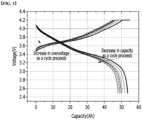
FIG. 1 is a graph showing an increase in overvoltage and a decrease in capacity as a cycle proceeds according to Reference Example 1. -
FIG. 2 is a graph showing a decrease in overvoltage and capacity recovery when a high temperature treatment is performed according to Example 1 after a cycle according to Experimental Example 1 proceeds. -
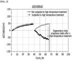
FIG. 3 is a graph showing a change in OCV according to cycles in Experimental Example 2. -
FIG. 4 is a graph showing a capacity retention rate according to cycles in Experimental Example 3. - Hereinafter, the present disclosure will be described in more detail through examples, but the following examples are for illustrative purposes only, and the scope of the present disclosure is not limited thereto.
- 0.5Li2MnO3·0.5Li(Ni0.45Mn0.35Ni0.20)O2 was used as the positive electrode active material, and the conductive material (carbon black) and the binder (PVdF) were added in a weight ratio of 90: 5: 4 to NMP(N-methyl-2-pyrrolidone), and mixed to prepare a positive electrode mixture.
- The prepared positive electrode mixture was coated onto a 20 µm thick aluminum foil to a thickness of 80 µm, then rolled and dried to manufacture a positive electrode.
- Artificial graphite was used as the positive electrode, and the conductive material (carbon black), and the binder (PVdF) were added in a weight ratio of 95:3: 2 to NMP(N-methyl-2-pyrrolidone) and mixed to prepare a negative electrode mixture.
- The prepared negative electrode mixture was coated onto a 20 µm thick copper foil to a thickness of 80 µm, then rolled and dried to manufacture a negative electrode.
- A separator (DB0901, BA1 SRS composition, thickness: 18 µm, cloth 9 µm, total coating thickness of 9 µm, coated to a thickness of 4.5 µm per one surface of SRS) was interposed between the positive electrode and the negative electrode, and laminated at a linear pressure of 1 kgf/mm to manufacture an electrode assembly. The electrode assembly was then housed in a pouch-type battery case, and a non-aqueous electrolyte, in which ethyl carbonate, dimethyl carbonate, and ethyl methyl carbonate were mixed at a volume ratio of 1:1:1 and a non-aqueous electrolyte solution containing 1M LiPF6 as a lithium salt was contained, was added thereto to manufacture a pouch type lithium battery cell.
- The process of charging the lithium battery cell prepared in Preparation Example to 4.2V at 0.33C and discharging it to 2.5V at 1.0C was repeated to measure the changes in capacity and voltage according to the proceeding of the cycle.
- The results of proceeding the cycle up to 40 times are shown in
FIG. 1 below. - Referring to
FIG. 1 , it can be seen that as the cycle proceeds, the changes in capacity and voltage move along an arrow direction, so that the overvoltage increases and the capacity decreases. - The discharge capacity was measured with a charging/discharging device from the PNE Company while repeating the process of charging the lithium battery cell prepared in the preparation example to 4.2V at 0.33C in a 25°C chamber and discharging it to 2.5V at 1.0C. When the discharge capacity reached about 90% of an initial discharge capacity (degeneration rate: 10%, 40 cycles), the cycle was stopped. The battery cell was subjected to a high temperature treatment at 80°C for 6 hours in a state of
SOC 0. - The process of charging the battery cell subjected to the high temperature treatment in Example 1 to 4.2V at 0.33C and discharging it to 2.5V at 1.0C was repeated once to measure the changes in capacity and voltage, and the results are shown in
FIG. 2 . - Referring to
FIG. 2 , it can be seen that almost the same aspect as the initial capacity and voltage was exhibited by the high temperature treatment. - In order to more clearly show the recovery due to the high temperature treatment, the voltage increase and the capacity decrease according to the cycle before the high temperature treatment were indicated in gray.
- Four lithium battery cells prepared in Preparation Examples were prepared The discharge capacity was measured with a charging/discharging device (PNE Company) while repeating the process of charging the lithium battery cell to 4.2V at 0.33C in a 25°C chamber and discharging it to 2.5V at 1.0e. When the discharge capacity reached about 90% of the initial discharge capacity (degeneration rate: 10%, 40 cycles), the cycle was stopped. Two of the lithium battery cells were stored at 25°C for 6 hours in the state of
SOC 0, the other two were subjected to the high temperature treatment (stored) at 80°C for 6 hours. - The process of charging the lithium battery cells of Comparative Examples 1 to 2 and Examples 2 to 3 to 4.2V at 0.33C and discharging them to 2.5V at 1.0C was repeated again.
- While discharging the battery cells of Comparative Examples 1 to 2 and Examples 2 to 3 from the beginning to the time when the discharge capacity become about 90% of the initial discharge capacity (degeneration rate: 10%, 40 cycles), each cycle had a rest time at which electricity was not allowed to flow when the discharge completed the corresponding cut-off discharge CV section (about 30 minutes). The difference of the OCV values in the last 30 minutes immediately after the discharge was completed was measured as a delta value, and then, the difference of the OCV values during the rest time according to the proceeding of the cycle after the storage or high temperature treatment was measured as a delta value. The results were shown in
FIG. 3 below. - In this case, an increase in the difference of the OCV values, i.e. the delta value indicates that so much overvoltage was applied and solved during the rest time, and thus, it is stable to go in a decreasing direction.
- Meanwhile, in the figure, each graph of the Comparative Examples and the Examples is overlapped and it appears as a single graph.
- Referring to
FIG. 3 , it can be seen that the lithium battery cell of Example 1 subjected to the high temperature treatment induces a decrease in the OCV after the high temperature treatment and proceeds stably, whereas the lithium battery cell of Comparative Example 1 not subjected to the high temperature treatment exhibits a form of degeneration progression in which the OCV increases. - The process of charging the lithium battery cells of Comparative Examples 1 to 2 and Examples 2 to 3 to 4.2V at 0.33C and discharging them to 2.5V at 1.0C was repeated again.
- The capacity retention rate according to the cycle before and after the treatment of the lithium battery cells of Comparative Examples 1 ~ 2 and Examples 2 ~ 3 was measured from the beginning (charging/discharging device manufactured by PNE company), and the results were shown in
FIG. 4 below. - Referring to
FIG. 4 , it can be seen that the lithium battery cell of Example 1 subjected to the high temperature treatment recovered almost 98% or more of the capacity after the high temperature treatment, and then, this capacity was maintained at a capacity retention rate of 95% or more for 100 cycles or more (for 140 cycles or more in the graph), whereas the capacity retention rate of the lithium battery cell of Comparative Example 1 not subjected to the high temperature treatment was rapidly decreased.
Claims (7)
- A method of recovering a degenerated lithium battery cell,with the lithium battery cell being configured so that an electrode assembly including a positive electrode, a negative electrode and a separator interposed therebetween is impregnated with a non-aqueous electrolyte and embedded in a battery case,the method comprising:subjecting the lithium battery cell degenerated by 5% or more to a high temperature treatment for 2 to 6 hours at a temperature ranging from 75°C to 90°C in a fully discharged state, andwherein the lithium battery cell subjected to the high temperature treatment recovers the discharge capacity to 98% or more of a discharge capacity which appears from a first charging and discharging,wherein the lithium battery cell to be subjected to the high temperature treatment is a lithium battery cell which satisfies the following Conditional Formula 1:
Degeneration rate (x%) = (Initial discharge capacity - the nth cycle discharge capacity)/(Initial discharge capacity)×100≥5 wherein n is an integer of 2 or more. - The method of claim 1, wherein the high temperature treatment is performed at 80°C for 6 hours.
- The method of claim 1, wherein the degeneration is calculated from a capacity reduction ratio based on an initial discharge capacity when charging and discharging are repeatedly performed.
- The method of claim 1, wherein the complete discharge is SOC 0 to 1.
- The method of claim 1, wherein the lithium battery cell having the degeneration rate of 10% to 50% is subjected to the high temperature treatment.
- The method of claim 1, wherein the lithium battery cell having the degeneration rate of 10% to 15% is subjected to the high temperature treatment.
- The method of claim 1, wherein the lithium battery cell subjected to the high temperature treatment exhibits a capacity retention rate of 95% or more for 100 cycles after the high temperature treatment.
Applications Claiming Priority (2)
| Application Number | Priority Date | Filing Date | Title |
|---|---|---|---|
| KR1020190101266A KR20210021822A (en) | 2019-08-19 | 2019-08-19 | Method For Recovering Lithium Battery Cell By Heat Treatment and Method For Manufacturing Lithium Battery Cell Comprising the Same |
| PCT/KR2020/008261 WO2021033904A1 (en) | 2019-08-19 | 2020-06-25 | Lithium battery cell restoring method using heat treatment, and lithium battery cell manufacturing method including same |
Publications (3)
| Publication Number | Publication Date |
|---|---|
| EP3826098A1 EP3826098A1 (en) | 2021-05-26 |
| EP3826098A4 EP3826098A4 (en) | 2021-12-01 |
| EP3826098B1 true EP3826098B1 (en) | 2024-12-18 |
Family
ID=74659610
Family Applications (1)
| Application Number | Title | Priority Date | Filing Date |
|---|---|---|---|
| EP20851401.8A Active EP3826098B1 (en) | 2019-08-19 | 2020-06-25 | Method for recovering lithium battery cell by heat treatment and method for manufacturing lithium battery cell comprising the same |
Country Status (8)
| Country | Link |
|---|---|
| US (1) | US12148892B2 (en) |
| EP (1) | EP3826098B1 (en) |
| KR (2) | KR20210021822A (en) |
| CN (1) | CN112714975B (en) |
| ES (1) | ES3006451T3 (en) |
| HU (1) | HUE069871T2 (en) |
| PL (1) | PL3826098T3 (en) |
| WO (1) | WO2021033904A1 (en) |
Families Citing this family (1)
| Publication number | Priority date | Publication date | Assignee | Title |
|---|---|---|---|---|
| JP6973213B2 (en) * | 2018-03-16 | 2021-11-24 | トヨタ自動車株式会社 | Secondary battery system and secondary battery control method |
Family Cites Families (21)
| Publication number | Priority date | Publication date | Assignee | Title |
|---|---|---|---|---|
| JP3332566B2 (en) | 1994-03-25 | 2002-10-07 | 三洋電機株式会社 | Stacked sealed nickel-hydrogen battery and maintenance method for recovering its capacity |
| JPH10289729A (en) | 1997-04-16 | 1998-10-27 | Fuji Photo Film Co Ltd | System for secondary battery system and manufacture of secondary battery and therefor |
| KR20070082379A (en) | 2006-02-16 | 2007-08-21 | 주식회사 엘지화학 | Manufacturing method of lithium secondary battery through high temperature pretreatment process |
| US20130115486A1 (en) | 2010-07-16 | 2013-05-09 | Nissan Motor Co., Ltd | Lithium ion secondary battery, battery capacity recovery apparatus, and battery capacity recovery method |
| JP2012028024A (en) * | 2010-07-20 | 2012-02-09 | Toyota Motor Corp | Capacity recovery method for lithium ion secondary battery |
| JP5644602B2 (en) | 2011-03-16 | 2014-12-24 | トヨタ自動車株式会社 | Battery system, vehicle, and capacity recovery method of lithium ion secondary battery |
| JP5728520B2 (en) | 2013-04-12 | 2015-06-03 | プライムアースEvエナジー株式会社 | Battery capacity recovery method, battery pack capacity recovery method, battery capacity recovery device, and battery pack capacity recovery device |
| KR101617415B1 (en) | 2013-07-31 | 2016-05-03 | 주식회사 엘지화학 | The Method for Preparing Lithium Secondary Battery and the Lithium Secondary Battery Prepared by Using the Same |
| JP2016126912A (en) | 2014-12-26 | 2016-07-11 | トヨタ自動車株式会社 | Method for restoring all-solid battery |
| CN108431994A (en) | 2015-08-11 | 2018-08-21 | 工业研究与发展基金会有限公司 | Lithium intercalation material coated with metal fluoride, preparation method and use thereof |
| KR101985812B1 (en) | 2015-08-18 | 2019-06-04 | 주식회사 엘지화학 | Charging limit evaluation method of battery, method and apparatus for fast charging using the same |
| KR101903225B1 (en) | 2015-08-21 | 2018-11-13 | 주식회사 엘지화학 | Apparatus for Estimating Degree-of-Aging of Secondary Battery and Method thereof |
| KR102164250B1 (en) * | 2016-06-23 | 2020-10-12 | 주식회사 엘지화학 | Peparing method for lithium secondary battery comprising high temperature and pressurization condition during formation process |
| KR101987528B1 (en) | 2016-09-26 | 2019-06-10 | 현대자동차주식회사 | System and method for battery management |
| JP6551749B2 (en) * | 2016-11-30 | 2019-07-31 | トヨタ自動車株式会社 | Secondary battery capacity recovery method and capacity recovery system |
| KR102603503B1 (en) * | 2016-12-26 | 2023-11-20 | 스미토모 긴조쿠 고잔 가부시키가이샤 | Positive electrode active material for non-aqueous electrolyte secondary battery, manufacturing method thereof, and non-aqueous electrolyte secondary battery |
| KR102453271B1 (en) | 2017-03-17 | 2022-10-12 | 주식회사 엘지에너지솔루션 | Electrolyte for lithium secondary battery and lithium secondary battery comprising the same |
| JP6958316B2 (en) * | 2017-12-14 | 2021-11-02 | トヨタ自動車株式会社 | Battery system and lithium-ion secondary battery capacity recovery method |
| KR102315071B1 (en) | 2017-12-28 | 2021-10-21 | 주식회사 엘지에너지솔루션 | Reusing method for end of life cell |
| KR102550766B1 (en) | 2018-02-22 | 2023-07-04 | 엘지전자 주식회사 | Laundry treating apparatus and method for controlling the laundry treating apparatus |
| KR102508853B1 (en) | 2019-06-12 | 2023-03-09 | 주식회사 엘지에너지솔루션 | Manufacturing Method of Lithium Secondary Battery Comprising Additional Heat-treatment Process and Lithium Secondary Battery Manufactured by the Same |
-
2019
- 2019-08-19 KR KR1020190101266A patent/KR20210021822A/en not_active Ceased
-
2020
- 2020-06-25 HU HUE20851401A patent/HUE069871T2/en unknown
- 2020-06-25 WO PCT/KR2020/008261 patent/WO2021033904A1/en not_active Ceased
- 2020-06-25 ES ES20851401T patent/ES3006451T3/en active Active
- 2020-06-25 EP EP20851401.8A patent/EP3826098B1/en active Active
- 2020-06-25 US US17/274,974 patent/US12148892B2/en active Active
- 2020-06-25 PL PL20851401.8T patent/PL3826098T3/en unknown
- 2020-06-25 CN CN202080004583.9A patent/CN112714975B/en active Active
-
2024
- 2024-02-21 KR KR1020240024873A patent/KR20240029017A/en not_active Ceased
Also Published As
| Publication number | Publication date |
|---|---|
| EP3826098A1 (en) | 2021-05-26 |
| WO2021033904A1 (en) | 2021-02-25 |
| HUE069871T2 (en) | 2025-04-28 |
| US20220158260A1 (en) | 2022-05-19 |
| KR20210021822A (en) | 2021-03-02 |
| CN112714975B (en) | 2024-05-07 |
| PL3826098T3 (en) | 2025-03-10 |
| KR20240029017A (en) | 2024-03-05 |
| CN112714975A (en) | 2021-04-27 |
| EP3826098A4 (en) | 2021-12-01 |
| ES3006451T3 (en) | 2025-03-18 |
| US12148892B2 (en) | 2024-11-19 |
Similar Documents
| Publication | Publication Date | Title |
|---|---|---|
| US11799068B2 (en) | Multilayer electrode and method of manufacturing same | |
| EP3399576B1 (en) | Multilayer anode having, in each layer, different amounts of binder and different active material grain size, and lithium secondary battery comprising same | |
| US11876191B2 (en) | Method for activating secondary battery | |
| KR101540618B1 (en) | Electrode for Secondary Battery and Method of Preparing the Same | |
| US9673444B2 (en) | Method of manufacturing electrode for lithium secondary battery and electrode manufactured using the same | |
| US12107229B2 (en) | Manufacturing method of lithium secondary battery comprising additional heat-treatment process and lithium secondary battery manufactured by the same | |
| EP3182487A1 (en) | Electrode with multilayer structure and lithium secondary battery having same | |
| KR100907621B1 (en) | A positive electrode mixture containing a conductive material of two components and a lithium secondary battery composed of it | |
| EP4030516B1 (en) | Method for manufacturing secondary battery | |
| KR102254353B1 (en) | Charging Method of Secondary Battery | |
| US20240021882A1 (en) | Cylindrical secondary battery having high structural safety and method of manufacturing the same | |
| KR101031179B1 (en) | Electrochemical device with improved safety against internal short circuit | |
| CN111052484A (en) | Liquid electrolyte additive for lithium secondary battery, non-aqueous liquid electrolyte containing the same, and lithium secondary battery | |
| US20240332517A1 (en) | Method for manufacturing negative electrode for lithium secondary battery | |
| CN110495022B (en) | Electrode without current collector and secondary battery including the same | |
| EP3832777B1 (en) | Jelly-roll type electrode assembly having anode in which anode mixtures containing active material with different composition are formed on both sides of electrode current collector, secondary battery comprising the same, and device comprising the secondary battery | |
| KR20170025873A (en) | Lithium secondary battery and operating method thereof | |
| EP3826098B1 (en) | Method for recovering lithium battery cell by heat treatment and method for manufacturing lithium battery cell comprising the same | |
| KR20170025875A (en) | Lithium secondary battery and operating method thereof | |
| EP3567657B1 (en) | Cathode for lithium secondary battery and lithium secondary battery comprising same | |
| KR20200046634A (en) | Manufacturing method for asymmetric electrode and asymmetric electrode, secondary battery prepared by the same |
Legal Events
| Date | Code | Title | Description |
|---|---|---|---|
| STAA | Information on the status of an ep patent application or granted ep patent |
Free format text: STATUS: UNKNOWN |
|
| STAA | Information on the status of an ep patent application or granted ep patent |
Free format text: STATUS: THE INTERNATIONAL PUBLICATION HAS BEEN MADE |
|
| PUAI | Public reference made under article 153(3) epc to a published international application that has entered the european phase |
Free format text: ORIGINAL CODE: 0009012 |
|
| STAA | Information on the status of an ep patent application or granted ep patent |
Free format text: STATUS: REQUEST FOR EXAMINATION WAS MADE |
|
| 17P | Request for examination filed |
Effective date: 20210219 |
|
| AK | Designated contracting states |
Kind code of ref document: A1 Designated state(s): AL AT BE BG CH CY CZ DE DK EE ES FI FR GB GR HR HU IE IS IT LI LT LU LV MC MK MT NL NO PL PT RO RS SE SI SK SM TR |
|
| A4 | Supplementary search report drawn up and despatched |
Effective date: 20211102 |
|
| RIC1 | Information provided on ipc code assigned before grant |
Ipc: H01M 10/0525 20100101ALI20211026BHEP Ipc: H01M 50/105 20210101ALI20211026BHEP Ipc: H01M 10/052 20100101ALI20211026BHEP Ipc: H01M 10/058 20100101ALI20211026BHEP Ipc: H01M 10/42 20060101AFI20211026BHEP |
|
| RAP1 | Party data changed (applicant data changed or rights of an application transferred) |
Owner name: LG ENERGY SOLUTION LTD. |
|
| RAP3 | Party data changed (applicant data changed or rights of an application transferred) |
Owner name: LG ENERGY SOLUTION, LTD. |
|
| DAV | Request for validation of the european patent (deleted) | ||
| DAX | Request for extension of the european patent (deleted) | ||
| STAA | Information on the status of an ep patent application or granted ep patent |
Free format text: STATUS: EXAMINATION IS IN PROGRESS |
|
| 17Q | First examination report despatched |
Effective date: 20230125 |
|
| GRAP | Despatch of communication of intention to grant a patent |
Free format text: ORIGINAL CODE: EPIDOSNIGR1 |
|
| STAA | Information on the status of an ep patent application or granted ep patent |
Free format text: STATUS: GRANT OF PATENT IS INTENDED |
|
| GRAS | Grant fee paid |
Free format text: ORIGINAL CODE: EPIDOSNIGR3 |
|
| INTG | Intention to grant announced |
Effective date: 20241009 |
|
| GRAA | (expected) grant |
Free format text: ORIGINAL CODE: 0009210 |
|
| STAA | Information on the status of an ep patent application or granted ep patent |
Free format text: STATUS: THE PATENT HAS BEEN GRANTED |
|
| P01 | Opt-out of the competence of the unified patent court (upc) registered |
Free format text: CASE NUMBER: APP_59652/2024 Effective date: 20241104 |
|
| AK | Designated contracting states |
Kind code of ref document: B1 Designated state(s): AL AT BE BG CH CY CZ DE DK EE ES FI FR GB GR HR HU IE IS IT LI LT LU LV MC MK MT NL NO PL PT RO RS SE SI SK SM TR |
|
| REG | Reference to a national code |
Ref country code: CH Ref legal event code: EP |
|
| REG | Reference to a national code |
Ref country code: DE Ref legal event code: R096 Ref document number: 602020043476 Country of ref document: DE |
|
| REG | Reference to a national code |
Ref country code: IE Ref legal event code: FG4D |
|
| REG | Reference to a national code |
Ref country code: SE Ref legal event code: TRGR |
|
| REG | Reference to a national code |
Ref country code: ES Ref legal event code: FG2A Ref document number: 3006451 Country of ref document: ES Kind code of ref document: T3 Effective date: 20250318 |
|
| REG | Reference to a national code |
Ref country code: LT Ref legal event code: MG9D |
|
| PG25 | Lapsed in a contracting state [announced via postgrant information from national office to epo] |
Ref country code: HR Free format text: LAPSE BECAUSE OF FAILURE TO SUBMIT A TRANSLATION OF THE DESCRIPTION OR TO PAY THE FEE WITHIN THE PRESCRIBED TIME-LIMIT Effective date: 20241218 |
|
| PG25 | Lapsed in a contracting state [announced via postgrant information from national office to epo] |
Ref country code: FI Free format text: LAPSE BECAUSE OF FAILURE TO SUBMIT A TRANSLATION OF THE DESCRIPTION OR TO PAY THE FEE WITHIN THE PRESCRIBED TIME-LIMIT Effective date: 20241218 |
|
| PG25 | Lapsed in a contracting state [announced via postgrant information from national office to epo] |
Ref country code: BG Free format text: LAPSE BECAUSE OF FAILURE TO SUBMIT A TRANSLATION OF THE DESCRIPTION OR TO PAY THE FEE WITHIN THE PRESCRIBED TIME-LIMIT Effective date: 20241218 |
|
| PG25 | Lapsed in a contracting state [announced via postgrant information from national office to epo] |
Ref country code: NO Free format text: LAPSE BECAUSE OF FAILURE TO SUBMIT A TRANSLATION OF THE DESCRIPTION OR TO PAY THE FEE WITHIN THE PRESCRIBED TIME-LIMIT Effective date: 20250318 |
|
| REG | Reference to a national code |
Ref country code: NL Ref legal event code: MP Effective date: 20241218 |
|
| PG25 | Lapsed in a contracting state [announced via postgrant information from national office to epo] |
Ref country code: LV Free format text: LAPSE BECAUSE OF FAILURE TO SUBMIT A TRANSLATION OF THE DESCRIPTION OR TO PAY THE FEE WITHIN THE PRESCRIBED TIME-LIMIT Effective date: 20241218 Ref country code: GR Free format text: LAPSE BECAUSE OF FAILURE TO SUBMIT A TRANSLATION OF THE DESCRIPTION OR TO PAY THE FEE WITHIN THE PRESCRIBED TIME-LIMIT Effective date: 20250319 |
|
| REG | Reference to a national code |
Ref country code: HU Ref legal event code: AG4A Ref document number: E069871 Country of ref document: HU |
|
| PG25 | Lapsed in a contracting state [announced via postgrant information from national office to epo] |
Ref country code: RS Free format text: LAPSE BECAUSE OF FAILURE TO SUBMIT A TRANSLATION OF THE DESCRIPTION OR TO PAY THE FEE WITHIN THE PRESCRIBED TIME-LIMIT Effective date: 20250318 |
|
| PG25 | Lapsed in a contracting state [announced via postgrant information from national office to epo] |
Ref country code: NL Free format text: LAPSE BECAUSE OF FAILURE TO SUBMIT A TRANSLATION OF THE DESCRIPTION OR TO PAY THE FEE WITHIN THE PRESCRIBED TIME-LIMIT Effective date: 20241218 |
|
| REG | Reference to a national code |
Ref country code: AT Ref legal event code: MK05 Ref document number: 1752996 Country of ref document: AT Kind code of ref document: T Effective date: 20241218 |
|
| PG25 | Lapsed in a contracting state [announced via postgrant information from national office to epo] |
Ref country code: SM Free format text: LAPSE BECAUSE OF FAILURE TO SUBMIT A TRANSLATION OF THE DESCRIPTION OR TO PAY THE FEE WITHIN THE PRESCRIBED TIME-LIMIT Effective date: 20241218 |
|
| PGFP | Annual fee paid to national office [announced via postgrant information from national office to epo] |
Ref country code: PL Payment date: 20250522 Year of fee payment: 6 Ref country code: DE Payment date: 20250520 Year of fee payment: 6 |
|
| PGFP | Annual fee paid to national office [announced via postgrant information from national office to epo] |
Ref country code: GB Payment date: 20250520 Year of fee payment: 6 |
|
| PG25 | Lapsed in a contracting state [announced via postgrant information from national office to epo] |
Ref country code: IS Free format text: LAPSE BECAUSE OF FAILURE TO SUBMIT A TRANSLATION OF THE DESCRIPTION OR TO PAY THE FEE WITHIN THE PRESCRIBED TIME-LIMIT Effective date: 20250418 |
|
| PGFP | Annual fee paid to national office [announced via postgrant information from national office to epo] |
Ref country code: BE Payment date: 20250407 Year of fee payment: 6 |
|
| PG25 | Lapsed in a contracting state [announced via postgrant information from national office to epo] |
Ref country code: PT Free format text: LAPSE BECAUSE OF FAILURE TO SUBMIT A TRANSLATION OF THE DESCRIPTION OR TO PAY THE FEE WITHIN THE PRESCRIBED TIME-LIMIT Effective date: 20250421 |
|
| PG25 | Lapsed in a contracting state [announced via postgrant information from national office to epo] |
Ref country code: EE Free format text: LAPSE BECAUSE OF FAILURE TO SUBMIT A TRANSLATION OF THE DESCRIPTION OR TO PAY THE FEE WITHIN THE PRESCRIBED TIME-LIMIT Effective date: 20241218 |
|
| PGFP | Annual fee paid to national office [announced via postgrant information from national office to epo] |
Ref country code: HU Payment date: 20250623 Year of fee payment: 6 Ref country code: FR Payment date: 20250521 Year of fee payment: 6 |
|
| PG25 | Lapsed in a contracting state [announced via postgrant information from national office to epo] |
Ref country code: AT Free format text: LAPSE BECAUSE OF FAILURE TO SUBMIT A TRANSLATION OF THE DESCRIPTION OR TO PAY THE FEE WITHIN THE PRESCRIBED TIME-LIMIT Effective date: 20241218 Ref country code: RO Free format text: LAPSE BECAUSE OF FAILURE TO SUBMIT A TRANSLATION OF THE DESCRIPTION OR TO PAY THE FEE WITHIN THE PRESCRIBED TIME-LIMIT Effective date: 20241218 |
|
| PG25 | Lapsed in a contracting state [announced via postgrant information from national office to epo] |
Ref country code: SK Free format text: LAPSE BECAUSE OF FAILURE TO SUBMIT A TRANSLATION OF THE DESCRIPTION OR TO PAY THE FEE WITHIN THE PRESCRIBED TIME-LIMIT Effective date: 20241218 |
|
| PG25 | Lapsed in a contracting state [announced via postgrant information from national office to epo] |
Ref country code: CZ Free format text: LAPSE BECAUSE OF FAILURE TO SUBMIT A TRANSLATION OF THE DESCRIPTION OR TO PAY THE FEE WITHIN THE PRESCRIBED TIME-LIMIT Effective date: 20241218 |
|
| PG25 | Lapsed in a contracting state [announced via postgrant information from national office to epo] |
Ref country code: IT Free format text: LAPSE BECAUSE OF FAILURE TO SUBMIT A TRANSLATION OF THE DESCRIPTION OR TO PAY THE FEE WITHIN THE PRESCRIBED TIME-LIMIT Effective date: 20241218 |
|
| PGFP | Annual fee paid to national office [announced via postgrant information from national office to epo] |
Ref country code: SE Payment date: 20250523 Year of fee payment: 6 |
|
| REG | Reference to a national code |
Ref country code: DE Ref legal event code: R097 Ref document number: 602020043476 Country of ref document: DE |
|
| PGFP | Annual fee paid to national office [announced via postgrant information from national office to epo] |
Ref country code: ES Payment date: 20250714 Year of fee payment: 6 |
|
| PG25 | Lapsed in a contracting state [announced via postgrant information from national office to epo] |
Ref country code: DK Free format text: LAPSE BECAUSE OF FAILURE TO SUBMIT A TRANSLATION OF THE DESCRIPTION OR TO PAY THE FEE WITHIN THE PRESCRIBED TIME-LIMIT Effective date: 20241218 |
|
| PLBE | No opposition filed within time limit |
Free format text: ORIGINAL CODE: 0009261 |
|
| STAA | Information on the status of an ep patent application or granted ep patent |
Free format text: STATUS: NO OPPOSITION FILED WITHIN TIME LIMIT |
|
| REG | Reference to a national code |
Ref country code: CH Ref legal event code: L10 Free format text: ST27 STATUS EVENT CODE: U-0-0-L10-L00 (AS PROVIDED BY THE NATIONAL OFFICE) Effective date: 20251029 |
|
| 26N | No opposition filed |
Effective date: 20250919 |
|
| REG | Reference to a national code |
Ref country code: CH Ref legal event code: H13 Free format text: ST27 STATUS EVENT CODE: U-0-0-H10-H13 (AS PROVIDED BY THE NATIONAL OFFICE) Effective date: 20260127 |
|
| PG25 | Lapsed in a contracting state [announced via postgrant information from national office to epo] |
Ref country code: MC Free format text: LAPSE BECAUSE OF FAILURE TO SUBMIT A TRANSLATION OF THE DESCRIPTION OR TO PAY THE FEE WITHIN THE PRESCRIBED TIME-LIMIT Effective date: 20241218 |
|
| PG25 | Lapsed in a contracting state [announced via postgrant information from national office to epo] |
Ref country code: LU Free format text: LAPSE BECAUSE OF NON-PAYMENT OF DUE FEES Effective date: 20250625 |
|
| PG25 | Lapsed in a contracting state [announced via postgrant information from national office to epo] |
Ref country code: IE Free format text: LAPSE BECAUSE OF NON-PAYMENT OF DUE FEES Effective date: 20250625 |
|
| PG25 | Lapsed in a contracting state [announced via postgrant information from national office to epo] |
Ref country code: CH Free format text: LAPSE BECAUSE OF NON-PAYMENT OF DUE FEES Effective date: 20250630 |