EP3826088B1 - Electrode for lithium secondary battery and lithium secondary battery comprising same - Google Patents
Electrode for lithium secondary battery and lithium secondary battery comprising same Download PDFInfo
- Publication number
- EP3826088B1 EP3826088B1 EP19846618.7A EP19846618A EP3826088B1 EP 3826088 B1 EP3826088 B1 EP 3826088B1 EP 19846618 A EP19846618 A EP 19846618A EP 3826088 B1 EP3826088 B1 EP 3826088B1
- Authority
- EP
- European Patent Office
- Prior art keywords
- electrode
- lithium secondary
- secondary battery
- hfp
- binder
- Prior art date
- Legal status (The legal status is an assumption and is not a legal conclusion. Google has not performed a legal analysis and makes no representation as to the accuracy of the status listed.)
- Active
Links
Images
Classifications
-
- H—ELECTRICITY
- H01—ELECTRIC ELEMENTS
- H01M—PROCESSES OR MEANS, e.g. BATTERIES, FOR THE DIRECT CONVERSION OF CHEMICAL ENERGY INTO ELECTRICAL ENERGY
- H01M4/00—Electrodes
- H01M4/02—Electrodes composed of, or comprising, active material
- H01M4/13—Electrodes for accumulators with non-aqueous electrolyte, e.g. for lithium-accumulators; Processes of manufacture thereof
-
- H—ELECTRICITY
- H01—ELECTRIC ELEMENTS
- H01M—PROCESSES OR MEANS, e.g. BATTERIES, FOR THE DIRECT CONVERSION OF CHEMICAL ENERGY INTO ELECTRICAL ENERGY
- H01M10/00—Secondary cells; Manufacture thereof
- H01M10/05—Accumulators with non-aqueous electrolyte
- H01M10/052—Li-accumulators
- H01M10/0525—Rocking-chair batteries, i.e. batteries with lithium insertion or intercalation in both electrodes; Lithium-ion batteries
-
- H—ELECTRICITY
- H01—ELECTRIC ELEMENTS
- H01M—PROCESSES OR MEANS, e.g. BATTERIES, FOR THE DIRECT CONVERSION OF CHEMICAL ENERGY INTO ELECTRICAL ENERGY
- H01M10/00—Secondary cells; Manufacture thereof
- H01M10/42—Methods or arrangements for servicing or maintenance of secondary cells or secondary half-cells
- H01M10/4235—Safety or regulating additives or arrangements in electrodes, separators or electrolyte
-
- H—ELECTRICITY
- H01—ELECTRIC ELEMENTS
- H01M—PROCESSES OR MEANS, e.g. BATTERIES, FOR THE DIRECT CONVERSION OF CHEMICAL ENERGY INTO ELECTRICAL ENERGY
- H01M4/00—Electrodes
- H01M4/02—Electrodes composed of, or comprising, active material
- H01M4/04—Processes of manufacture in general
- H01M4/0402—Methods of deposition of the material
- H01M4/0404—Methods of deposition of the material by coating on electrode collectors
-
- H—ELECTRICITY
- H01—ELECTRIC ELEMENTS
- H01M—PROCESSES OR MEANS, e.g. BATTERIES, FOR THE DIRECT CONVERSION OF CHEMICAL ENERGY INTO ELECTRICAL ENERGY
- H01M4/00—Electrodes
- H01M4/02—Electrodes composed of, or comprising, active material
- H01M4/62—Selection of inactive substances as ingredients for active masses, e.g. binders, fillers
- H01M4/621—Binders
- H01M4/622—Binders being polymers
- H01M4/623—Binders being polymers fluorinated polymers
-
- H—ELECTRICITY
- H01—ELECTRIC ELEMENTS
- H01M—PROCESSES OR MEANS, e.g. BATTERIES, FOR THE DIRECT CONVERSION OF CHEMICAL ENERGY INTO ELECTRICAL ENERGY
- H01M4/00—Electrodes
- H01M4/02—Electrodes composed of, or comprising, active material
- H01M4/62—Selection of inactive substances as ingredients for active masses, e.g. binders, fillers
- H01M4/624—Electric conductive fillers
-
- H—ELECTRICITY
- H01—ELECTRIC ELEMENTS
- H01M—PROCESSES OR MEANS, e.g. BATTERIES, FOR THE DIRECT CONVERSION OF CHEMICAL ENERGY INTO ELECTRICAL ENERGY
- H01M4/00—Electrodes
- H01M4/02—Electrodes composed of, or comprising, active material
- H01M4/64—Carriers or collectors
- H01M4/66—Selection of materials
- H01M4/665—Composites
- H01M4/667—Composites in the form of layers, e.g. coatings
-
- Y—GENERAL TAGGING OF NEW TECHNOLOGICAL DEVELOPMENTS; GENERAL TAGGING OF CROSS-SECTIONAL TECHNOLOGIES SPANNING OVER SEVERAL SECTIONS OF THE IPC; TECHNICAL SUBJECTS COVERED BY FORMER USPC CROSS-REFERENCE ART COLLECTIONS [XRACs] AND DIGESTS
- Y02—TECHNOLOGIES OR APPLICATIONS FOR MITIGATION OR ADAPTATION AGAINST CLIMATE CHANGE
- Y02E—REDUCTION OF GREENHOUSE GAS [GHG] EMISSIONS, RELATED TO ENERGY GENERATION, TRANSMISSION OR DISTRIBUTION
- Y02E60/00—Enabling technologies; Technologies with a potential or indirect contribution to GHG emissions mitigation
- Y02E60/10—Energy storage using batteries
Definitions
- the present application claims priority to Korean Patent Application No. 10-2018-0092536 filed on August 8, 2018 in the Republic of Korea.
- the present disclosure relates to an electrode for a lithium secondary battery and a lithium secondary battery including the same. More particularly, the present disclosure relates to an electrode for a lithium secondary battery which can provide improved nail penetration safety and a lithium secondary battery including the same.
- lithium secondary batteries for vehicles developed recently it is required for lithium secondary batteries for vehicles developed recently to have high energy density and high output.
- development of lithium secondary batteries toward high energy density and output causes degradation of battery safety.
- a need for safety has been increased significantly. Particularly, when a battery pack is penetrated by external impact or deformation of appearance, explosion of manual devices, such as vehicles, may be generated.
- penetration safety has been regarded as an important item among the evaluation items for safety of lithium secondary batteries for vehicles, and many attempts have been made to improve this.
- KR 2018 0027953 A discloses an electrode having a coating layer.
- the present disclosure is designed to solve the problems of the related art, and therefore the present disclosure is directed to providing an electrode for a lithium secondary battery which can provide improved nail penetration safety and a lithium secondary battery including the same.
- an electrode for a lithium secondary battery as defined in the appended set of claims, the electrode which includes: an electrode current collector; a primer coating layer disposed on at least one surface of the electrode current collector and including a binder and a conductive material; and an electrode active material layer disposed on the primer coating layer, wherein the binder includes poly(vinylidene fluoride-co-hexafluoropropyene) (PVDF-HFP) containing vinylidene fluoride (VDF)-derived repeating units and hexafluoropropylene (HFP)-derived repeating units, the content of HFP-derived repeating units in PVDF-HFP is 2-13 wt%, and the primer coating layer has a thickness of 0.8-5 ⁇ m and wherein the primer coating layer includes the binder in an amount of 10-80 parts by weight based on 100 parts by weight of the conductive material.
- PVDF-HFP poly(vinylidene fluoride-co-hexafluoropropyene)
- the electrode for a lithium secondary battery as defined in the embodiment foregoing, wherein the primer coating layer includes the binder in an amount of 35-65 parts by weight based on 100 parts by weight of the conductive material.
- the electrode for a lithium secondary battery as defined in any one of the embodiments foregoing, wherein the content of HFP-derived repeating units in PVDF-HFP polymer is 3-10 wt%.
- the electrode for a lithium secondary battery as defined in any one of the embodiments foregoing, wherein the primer coating layer has a thickness of 1-2 ⁇ m.
- the electrode for a lithium secondary battery as defined in any one of the embodiments foregoing, wherein the primer coating layer has a thickness corresponding to 0.01-0.05 times of the thickness of the electrode active material layer.
- the electrode for a lithium secondary battery as defined in the embodiment foregoing, wherein the primer coating layer has a thickness corresponding to 0.01-0.03 times of the thickness of the electrode active material layer.
- the electrode for a lithium secondary battery as defined in any one of the embodiments foregoing, wherein the binder includes PVDF-HFP in an amount of 50 wt% or more based on 100 wt% of the binder.
- the electrode for a lithium secondary battery as defined in any one of the embodiments foregoing, wherein the electrode active material layer includes an electrode binder, and PVDF-HFP is used in an amount of 5 wt% or less based on 100 wt% of the electrode binder.
- a lithium secondary battery including a positive electrode, a negative electrode and a separator interposed between the positive electrode and the negative electrode, wherein the positive electrode or the negative electrode is the electrode as defined in any one of the embodiments foregoing.
- the electrode for a lithium secondary battery includes a primer coating layer, which includes PVDF-HFP as a binder and a conductive material, interposed between the electrode current collector and the electrode active material layer, and thus can increase the interfacial resistance between the electrode current collector and the electrode active material layer, and reduce the amount of short-circuit current flowing thorough a nail, even when nail penetration occurs, and thus can improve the safety of a battery ultimately.
- a primer coating layer which includes PVDF-HFP as a binder and a conductive material, interposed between the electrode current collector and the electrode active material layer, and thus can increase the interfacial resistance between the electrode current collector and the electrode active material layer, and reduce the amount of short-circuit current flowing thorough a nail, even when nail penetration occurs, and thus can improve the safety of a battery ultimately.
- HFP contained in PVDF-HFP improves thermal safety of the binder, and thus can reduce the temperature in the battery caused by IR-heating.
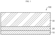
- FIG. 1 is a schematic view illustrating the structure of the electrode for a lithium secondary battery according to an embodiment of the present disclosure.
- a negative electrode 100 for a lithium secondary battery as shown in FIG. 1 .
- the negative electrode 100 for a lithium secondary battery includes: an electrode current collector 10; a primer coating layer 20 disposed on at least one surface of the electrode current collector and containing a binder and a conductive material; and an electrode active material layer 30 disposed on the primer coating layer.
- the electrode current collector 10 is not particularly limited, as long as it has conductivity while not causing any chemical change in a battery.
- the electrode current collector that may be used includes copper, stainless steel, aluminum, nickel, titanium, baked carbon, copper or stainless steel surface-treated with carbon, nickel, titanium, silver, etc., aluminum-cadmium alloy, or the like.
- the thickness of the electrode current collector is not particularly limited, but may be 3-500 ⁇ m as applied conventionally in the art.
- the primer coating layer 20 may include, as a binder, poly(vinylidene fluoride-co-hexafluoropropyene) (PVDF-HFP) containing vinylidene fluoride (VDF)-derived repeating units and hexafluoropropylene (HFP)-derived repeating units.
- PVDF-HFP poly(vinylidene fluoride-co-hexafluoropropyene)
- VDF vinylidene fluoride
- HFP hexafluoropropylene
- the content of PVDF-HFP may be 50 wt% or more, 80 wt% or more, 90 wt% or more, or 99 wt% or more, based on 100 wt% of the binder.
- HFP contained in PVDF-HFP characteristically shows an increase in absorbability to an organic electrolyte, and thus the degree of swelling of the PVDF-HFP binder may be controlled depending on the content of HFP. That is, as the HFP content increases, the swelling of the PVDF-HFP binder also increases.
- the primer coating layer includes PVDF-HFP as a binder, instead of the electrode active material layer, thus, the above-mentioned side effect is not problematic.
- the primer coating layer including PVDF-HFP as a binder is disposed between the electrode current collector and the electrode active material layer, and thus can increase the interfacial resistance between the electrode current collector and the electrode active material layer while not affecting swelling of the whole electrode substantially. As a result, even when nail penetration occurs, it is possible to reduce the amount of short-circuit current flowing in the nail, thereby improving the battery safety ultimately.
- HFP improves the thermal safety of the binder, and thus can reduce the temperature in the battery caused by IR-heating.
- the primer coating layer disposed between the electrode current collector and the electrode active material layer includes PVDF-HFP binder containing HFP-derived repeating units in an amount of 2-13 wt%, particularly 3-10 wt%, and more particularly 3-7 wt%.
- the binder may not be swelled sufficiently with HFP and thermal safety cannot be ensured sufficiently.
- the binder shows degradation of adhesive property, which is a main function of the binder, and excessive swelling occurs to cause an excessive increase in resistance of the primer coating layer, resulting in degradation of life characteristics.
- the weight-based content of repeating units may be determined by using 1 H-NMR, such as Varian 500 Model.
- the primer coating layer should have a significantly smaller thickness as compared to the electrode active material layer so that it may have little effect upon the swelling of the whole electrode.
- the primer coating layer preferably has a thickness of 0.8-5 ⁇ m, particularly 1-2 ⁇ m, and more particularly 1-1.5 ⁇ m.
- the primer coating layer has a thickness less than 0.8 ⁇ m, it is not possible to provide an effect of increasing resistance and swelling sufficiently.
- the primer coating layer has a thickness larger than 10 ⁇ m, resistance and swelling are increased excessively, resulting in the problem of degradation of life characteristics.
- the thickness of the primer coating layer is controlled preferably to 0.01-0.05 times, particularly 0.01-0.03 times of the thickness of the electrode active material layer.
- the primer coating layer may include the PVDF-HFP binder in an amount of 10-80 parts by weight, particularly 35-65 parts by weight, and more particularly 40-50 parts by weight, based on 100 parts by weight of the conductive material.
- the content of the PVDF-HFP binder satisfies the above-defined range, it is possible to reduce the amount of short-circuit current upon nail penetration while maintaining adhesion to an electrode, which is an essential purpose of a binder, and thus to provide an effect of improving safety.
- the primer coating layer may be formed by applying slurry obtained by dispersing PVDF-HFP as a binder and a conductive material in a solvent onto at least one surface of an electrode current collector.
- the conductive material may be one used currently for an electrode active material layer.
- the conductive material may include any one selected from graphite, such as natural graphite or artificial graphite; carbon black, such as acetylene black, Ketjen black, channel black, furnace black, lamp black or thermal black; conductive fibers, such as carbon fibers or metallic fibers; metal powder, such as aluminum or nickel powder; conductive whisker, such as zinc oxide or potassium titanate; conductive metal oxide, such as titanium oxide; and conductive materials, such as polyphenylene derivatives, or a mixture of two or more of them.
- graphite such as natural graphite or artificial graphite
- carbon black such as acetylene black, Ketjen black, channel black, furnace black, lamp black or thermal black
- conductive fibers such as carbon fibers or metallic fibers
- metal powder such as aluminum or nickel powder
- conductive whisker such as zinc oxide or potassium titanate
- conductive metal oxide such as titanium oxide
- conductive materials such as polyphenylene
- the electrode active material layer 30 may be formed by applying electrode slurry obtained by dispersing an active material, electrode binder and a conductive material in a solvent onto the primer coating layer 20, followed by drying and pressing.
- the positive electrode active material may be any material used conventionally as a positive electrode active material for a lithium secondary battery.
- the positive electrode active material may include, but are not limited to: layered compounds such as lithium cobalt oxide (LiCoO 2 ) and lithium nickel oxide (LiNiO 2 ), or those compounds substituted with one or more transition metals; lithium manganese oxides such as those represented by the chemical formula of Li 1+x Mn 2-x O 4 (wherein x is 0-0.33), LiMnO 3 , LiMn 2 O 3 and LiMnO 2 ; lithium copper oxide (Li 2 CuO 2 ); vanadium oxides such as LiVsOs, LiV 3 O 4 , V 2 O 5 or Cu 12 V 2 O 7 ; Ni-site type lithium nickel oxides represented by the chemical formula of LiNi 1-x M x O 2 (wherein M is Co, Mn, Al, Cu, Fe,
- the negative electrode active material may be any material used conventionally as a negative electrode active material for a lithium secondary battery.
- the negative electrode active material may include, but are not limited to: carbon such as non-graphitizable carbon, graphitic carbon (natural graphite, artificial graphite), or the like; metal composite oxides such as Li x Fe 2 O 3 (0 ⁇ x ⁇ 1), Li x WO 2 (0 ⁇ x ⁇ 1), Sn x Me 1-x Me' y O z (Me: Mn, Fe, Pb or Ge; Me': Al, B, P, Si, an element of Group 1, Group 2 or Group 3 in the Periodic Table, or halogen; 0 ⁇ x ⁇ 1; 1 ⁇ y ⁇ 3; 1 ⁇ z ⁇ 8); lithium metal; lithium alloys; silicon-based alloys; tin-based alloys; metal oxides such as SnO, S
- the conductive material is not particularly limited, as long as it causes no chemical change in the corresponding battery and has conductivity.
- the conductive material include any one selected from: graphite, such as natural graphite or artificial graphite; carbon black, such as acetylene black, Ketjen black, channel black, furnace black, lamp black or thermal black; conductive fibers, such as carbon fibers or metallic fibers; metal powder, such as aluminum or nickel powder; conductive whisker, such as zinc oxide or potassium titanate; conductive metal oxide, such as titanium oxide; and conductive materials, such as polyphenylene derivatives, or a mixture of two or more of them.
- the conductive material may be used in an amount of 0.1-20 wt%, particularly 1-10 wt%, based on the total weight of the electrode active material layer.
- the electrode binder may include at least one selected from: polyvinylidene fluoride (PVDF), polyvinylidene fluoride-co-trichloroethylene, polymethyl methacrylate, polyethylhexyl acrylate, polybutyl acrylate, polyacrylonitrile, polyviny1 pyrrolidone, polyvinyl acetate, polyethylene-co-vinyl acetate, polyethylene oxide, polyarylate, cellulose acetate, cellulose acetate butyrate, cellulose acetate propionate, cyanoethylpullulan, cyanoethy1polyvinyla1cho1, cyanoethyl cellulose, cyanoethyl sucrose, pullulan, styrene butadiene rubber (SBR), carboxymethyl cellulose, or the like, but the scope of the present disclosure is not limited thereto.
- PVDF polyvinylidene fluoride
- SBR styrene but
- PVDF-HFP is not suitable for a binder of an electrode due to the problem of battery swelling.
- the binder may be used in an amount of 20 wt% or less, 10 wt% or less, 5 wt% or less, or 1 wt% or less, based on the total weight of the electrode active material layer.
- the binder may be used in an amount of 0.1 wt% or less.
- the electrode binder may include PVDF-HFP in an amount of 5 wt% or less, 1 wt% or less, or 0.1 wt% or less, based on 100 wt% of the total electrode binder.
- a lithium secondary battery including a positive electrode, a negative electrode and a separator interposed between the positive electrode and the negative electrode, wherein the positive electrode or the negative electrode is the electrode for a lithium secondary battery according to an embodiment of the present disclosure.
- the electrode for a lithium secondary battery according to an embodiment of the present disclosure may be a positive electrode.
- the binder for the primer coating layer may be used together with an organic solvent when preparing the coating slurry, and the organic solvent is used more frequently when manufacturing a positive electrode, as compared to a negative electrode.
- the electrode for a lithium secondary battery may be applied more advisably to a positive electrode.
- the separator is interposed between the positive electrode and the negative electrode and functions to allow lithium ions to pass therethrough, while electrically insulating the positive electrode and the negative electrode from each other.
- the separator may be any separator used conventionally in the field of lithium secondary batteries with no particular limitation.
- the lithium secondary battery according to the present disclosure may be used for a battery module as a unit cell.
- the battery module may be used for a battery pack or a device including the battery pack as a power source.
- Particular examples of the device include, but are not limited to: electric vehicles, hybrid electric vehicles, plug-in hybrid electric vehicles, or electric power storage systems.
- the slurry for forming a primer coating layer was applied to an aluminum current collector having a thickness of 20 ⁇ m to a thickness of 2.4 ⁇ m, and then vacuum dried at 120°C for 24 hours to form a primer coating layer.
- the positive electrode slurry was applied to the primer coating layer formed from Step 1 to a thickness of 140 ⁇ m and vacuum dried at 120°C for 24 hours to form a positive electrode active material layer. Then, pressing was carried out to finish a positive electrode (thickness of the positive electrode active material layer after pressing: 70 ⁇ m, thickness of the primer coating layer after pressing: 1.2 ⁇ m, ratio of the thickness of primer coating layer based on the thickness of positive electrode active material layer in the finished positive electrode: 0.017).
- a positive electrode was obtained in the same manner as Example 1, except that PVDF-HFP (HFP content: 7 wt%) was used as a binder in Step 1.
- a positive electrode was obtained in the same manner as Example 1, except that PVDF (HFP content: 0 wt%) was used as a binder in Step 1.
- a positive electrode was obtained in the same manner as Example 1, except that PVDF-HFP (HFP content: 20 wt%) was used as a binder in Step 1.
- a positive electrode was obtained in the same manner as Example 1, except that thickness of primer coating layer after pressing was 0.3 ⁇ m and thickness of the positive electrode active material layer after pressing was 70 ⁇ m.
- a positive electrode was obtained in the same manner as Example 1, except that thickness of primer coating layer after pressing was 10 ⁇ m and thickness of the positive electrode active material layer after pressing was 70 ⁇ m.
- a polyethylene membrane (Celgard: thickness 20 ⁇ m) was interposed between each of the positive electrodes obtained from Examples and Comparative Examples and the negative electrode as described hereinafter. Then, an electrolyte containing 1M LiPF 6 dissolved in a mixed solvent containing ethylene carbonate, dimethylene carbonate and diethyl carbonate at a ratio of 1:2:1 was injected to obtain a lithium secondary battery. The performance of each lithium secondary battery was evaluated.
- the negative electrode was obtained by dispersing 96.3 wt% of artificial graphite as a negative electrode active material, 1.0 wt% of carbon black (Super P) as a conductive material and 2.7 wt% of PVDF as a binder into NMP as a solvent to prepare negative electrode slurry, and applying the negative electrode slurry onto copper foil having a thickness of 10 ⁇ m to a thickness of 160 ⁇ m, followed by drying and pressing.
- the negative electrode had a final thickness of 90 ⁇ m.
- Capacity retention (%) (Discharge capacity after 100 cycles / Discharge capacity at the 1 st cycle)x 100 [Table 1] Primer coating layer Coating layer thickness ( ⁇ m) Nail penetration safety thickness ( ⁇ m) Capacity retention (%) HFP content contained in PVDF-HFP binder (wt%) Ex. 1 3 1.2 2/5 98.1 Ex. 2 7 1.2 5/5 90.5 Comp. Ex. 1 0 1.2 0/5 98.8 Comp. Ex. 2 20 1.2 5/5 70.9 Comp. Ex. 3 3 0.3 0/5 98.9 Comp. Ex. 4 3 10 5/5 62.5
- Examples 1 and 2 in which the primer coating layer disposed between the electrode current collector and the electrode active material layer includes PVDF-HFP having a content of HFP-derived repeating units of 2-13 wt% and has a thickness of 0.8-5 ⁇ m ensure both nail penetration safety and high capacity retention.
- Comparative Examples 1-4 which cannot satisfy the above-defined range of HFP content and primer coating layer thickness provide poor results in terms of nail penetration safety or high capacity retention.
Landscapes
- Chemical & Material Sciences (AREA)
- Chemical Kinetics & Catalysis (AREA)
- Electrochemistry (AREA)
- General Chemical & Material Sciences (AREA)
- Engineering & Computer Science (AREA)
- Materials Engineering (AREA)
- Manufacturing & Machinery (AREA)
- Composite Materials (AREA)
- Battery Electrode And Active Subsutance (AREA)
- Cell Electrode Carriers And Collectors (AREA)
- Secondary Cells (AREA)
Description
- The present application claims priority to
Korean Patent Application No. 10-2018-0092536 filed on August 8, 2018 - It is required for lithium secondary batteries for vehicles developed recently to have high energy density and high output. However, development of lithium secondary batteries toward high energy density and output causes degradation of battery safety. In addition, as lithium secondary batteries have been increasingly in demand, a need for safety has been increased significantly. Particularly, when a battery pack is penetrated by external impact or deformation of appearance, explosion of manual devices, such as vehicles, may be generated. Thus, penetration safety has been regarded as an important item among the evaluation items for safety of lithium secondary batteries for vehicles, and many attempts have been made to improve this.
- Particularly, it is known that explosion caused by nail penetration results from local IR-heating due to short-circuit current derived from the contact between a nail and an electrode current collector, or between an electrode active material layer and an electrode current collector.
- To solve the problem related with such nail penetration safety, it is important to increase the interfacial resistance between an electrode active material layer and an electrode current collector. This is because high-rate current flows due to a short-circuit caused by nail penetration and electrons are transported from an electrode active material to an electrode current collector and a nail at that time. In this context, when resistance is increased, short-circuit current of nail penetration is reduced, and thus IR-heating can be reduced.
-
KR 2018 0027953 A - The present disclosure is designed to solve the problems of the related art, and therefore the present disclosure is directed to providing an electrode for a lithium secondary battery which can provide improved nail penetration safety and a lithium secondary battery including the same.
- According to the one embodiment of the present disclosure, there is provided an electrode for a lithium secondary battery as defined in the appended set of claims, the electrode which includes: an electrode current collector; a primer coating layer disposed on at least one surface of the electrode current collector and including a binder and a conductive material; and an electrode active material layer disposed on the primer coating layer, wherein the binder includes poly(vinylidene fluoride-co-hexafluoropropyene) (PVDF-HFP) containing vinylidene fluoride (VDF)-derived repeating units and hexafluoropropylene (HFP)-derived repeating units, the content of HFP-derived repeating units in PVDF-HFP is 2-13 wt%, and the primer coating layer has a thickness of 0.8-5 µm and wherein the primer coating layer includes the binder in an amount of 10-80 parts by weight based on 100 parts by weight of the conductive material.
- According to another embodiment of the present disclosure, there is provided the electrode for a lithium secondary battery as defined in the embodiment foregoing, wherein the primer coating layer includes the binder in an amount of 35-65 parts by weight based on 100 parts by weight of the conductive material.
- According to another embodiment of the present disclosure, there is provided the electrode for a lithium secondary battery as defined in any one of the embodiments foregoing, wherein the content of HFP-derived repeating units in PVDF-HFP polymer is 3-10 wt%.
- According to another embodiment of the present disclosure, there is provided the electrode for a lithium secondary battery as defined in any one of the embodiments foregoing, wherein the primer coating layer has a thickness of 1-2 µm.
- According to another embodiment of the present disclosure, there is provided the electrode for a lithium secondary battery as defined in any one of the embodiments foregoing, wherein the primer coating layer has a thickness corresponding to 0.01-0.05 times of the thickness of the electrode active material layer.
- According to another embodiment of the present disclosure, there is provided the electrode for a lithium secondary battery as defined in the embodiment foregoing, wherein the primer coating layer has a thickness corresponding to 0.01-0.03 times of the thickness of the electrode active material layer.
- According to another embodiment of the present disclosure, there is provided the electrode for a lithium secondary battery as defined in any one of the embodiments foregoing, wherein the binder includes PVDF-HFP in an amount of 50 wt% or more based on 100 wt% of the binder.
- According to another embodiment of the present disclosure, there is provided the electrode for a lithium secondary battery as defined in any one of the embodiments foregoing, wherein the electrode active material layer includes an electrode binder, and PVDF-HFP is used in an amount of 5 wt% or less based on 100 wt% of the electrode binder.
- In another aspect of the present disclosure, there is provided a lithium secondary battery including a positive electrode, a negative electrode and a separator interposed between the positive electrode and the negative electrode, wherein the positive electrode or the negative electrode is the electrode as defined in any one of the embodiments foregoing.
- The electrode for a lithium secondary battery according to an embodiment of the present disclosure includes a primer coating layer, which includes PVDF-HFP as a binder and a conductive material, interposed between the electrode current collector and the electrode active material layer, and thus can increase the interfacial resistance between the electrode current collector and the electrode active material layer, and reduce the amount of short-circuit current flowing thorough a nail, even when nail penetration occurs, and thus can improve the safety of a battery ultimately.
- In addition, HFP contained in PVDF-HFP improves thermal safety of the binder, and thus can reduce the temperature in the battery caused by IR-heating.
- The accompanying drawings illustrate a preferred embodiment of the present disclosure and together with the foregoing disclosure, serve to provide further understanding of the technical features of the present disclosure, and thus, the present disclosure is not construed as being limited to the drawing.
-
FIG. 1 is a schematic view illustrating the structure of the electrode for a lithium secondary battery according to an embodiment of the present disclosure. - Hereinafter, preferred embodiments of the present disclosure will be described in detail with reference to the accompanying drawings. Prior to the description, it should be understood that the terms used in the specification and the appended claims should not be construed as limited to general and dictionary meanings, but interpreted based on the meanings and concepts corresponding to technical aspects of the present disclosure on the basis of the principle that the inventor is allowed to define terms appropriately for the best explanation.
- Therefore, the description proposed herein is just a preferable example for the purpose of illustrations only, not intended to limit the scope of the disclosure, so it should be understood that modifications could be made thereto without departing from the scope of the disclosure.
- In one aspect of the present disclosure, there is provided a
negative electrode 100 for a lithium secondary battery, as shown inFIG. 1 . Thenegative electrode 100 for a lithium secondary battery includes: anelectrode current collector 10; aprimer coating layer 20 disposed on at least one surface of the electrode current collector and containing a binder and a conductive material; and an electrodeactive material layer 30 disposed on the primer coating layer. - According to an embodiment of the present disclosure, the electrode
current collector 10 is not particularly limited, as long as it has conductivity while not causing any chemical change in a battery. For example, the electrode current collector that may be used includes copper, stainless steel, aluminum, nickel, titanium, baked carbon, copper or stainless steel surface-treated with carbon, nickel, titanium, silver, etc., aluminum-cadmium alloy, or the like. - The thickness of the electrode current collector is not particularly limited, but may be 3-500 µm as applied conventionally in the art.
- According to an embodiment of the present disclosure, the
primer coating layer 20 may include, as a binder, poly(vinylidene fluoride-co-hexafluoropropyene) (PVDF-HFP) containing vinylidene fluoride (VDF)-derived repeating units and hexafluoropropylene (HFP)-derived repeating units. According to an embodiment of the present disclosure, the content of PVDF-HFP may be 50 wt% or more, 80 wt% or more, 90 wt% or more, or 99 wt% or more, based on 100 wt% of the binder. - HFP contained in PVDF-HFP characteristically shows an increase in absorbability to an organic electrolyte, and thus the degree of swelling of the PVDF-HFP binder may be controlled depending on the content of HFP. That is, as the HFP content increases, the swelling of the PVDF-HFP binder also increases.
- When using PVDF-HFP as a binder contained in the electrode active material layer, cycle characteristics may be degraded and swelling of a battery may be degraded to cause degradation of battery performance. On the contrary, in the present invention, the primer coating layer includes PVDF-HFP as a binder, instead of the electrode active material layer, thus, the above-mentioned side effect is not problematic.
- In other words, the primer coating layer including PVDF-HFP as a binder is disposed between the electrode current collector and the electrode active material layer, and thus can increase the interfacial resistance between the electrode current collector and the electrode active material layer while not affecting swelling of the whole electrode substantially. As a result, even when nail penetration occurs, it is possible to reduce the amount of short-circuit current flowing in the nail, thereby improving the battery safety ultimately.
- In addition, HFP improves the thermal safety of the binder, and thus can reduce the temperature in the battery caused by IR-heating.
- For these reasons, according to the present disclosure, the primer coating layer disposed between the electrode current collector and the electrode active material layer includes PVDF-HFP binder containing HFP-derived repeating units in an amount of 2-13 wt%, particularly 3-10 wt%, and more particularly 3-7 wt%. When the content of the HFP-derived repeating units is less than 2 wt%, the binder may not be swelled sufficiently with HFP and thermal safety cannot be ensured sufficiently. When the content of HFP is larger than 13 wt%, the binder shows degradation of adhesive property, which is a main function of the binder, and excessive swelling occurs to cause an excessive increase in resistance of the primer coating layer, resulting in degradation of life characteristics.
- According to the present disclosure, the weight-based content of repeating units may be determined by using 1H-NMR, such as Varian 500 Model.
- In addition, the primer coating layer should have a significantly smaller thickness as compared to the electrode active material layer so that it may have little effect upon the swelling of the whole electrode. In other words, the primer coating layer preferably has a thickness of 0.8-5 µm, particularly 1-2 µm, and more particularly 1-1.5 µm. When the primer coating layer has a thickness less than 0.8 µm, it is not possible to provide an effect of increasing resistance and swelling sufficiently. When the primer coating layer has a thickness larger than 10 µm, resistance and swelling are increased excessively, resulting in the problem of degradation of life characteristics.
- Particularly, the thickness of the primer coating layer is controlled preferably to 0.01-0.05 times, particularly 0.01-0.03 times of the thickness of the electrode active material layer.
- Meanwhile, the primer coating layer may include the PVDF-HFP binder in an amount of 10-80 parts by weight, particularly 35-65 parts by weight, and more particularly 40-50 parts by weight, based on 100 parts by weight of the conductive material. When the content of the PVDF-HFP binder satisfies the above-defined range, it is possible to reduce the amount of short-circuit current upon nail penetration while maintaining adhesion to an electrode, which is an essential purpose of a binder, and thus to provide an effect of improving safety.
- The primer coating layer may be formed by applying slurry obtained by dispersing PVDF-HFP as a binder and a conductive material in a solvent onto at least one surface of an electrode current collector.
- Herein, the conductive material may be one used currently for an electrode active material layer. For example, the conductive material may include any one selected from graphite, such as natural graphite or artificial graphite; carbon black, such as acetylene black, Ketjen black, channel black, furnace black, lamp black or thermal black; conductive fibers, such as carbon fibers or metallic fibers; metal powder, such as aluminum or nickel powder; conductive whisker, such as zinc oxide or potassium titanate; conductive metal oxide, such as titanium oxide; and conductive materials, such as polyphenylene derivatives, or a mixture of two or more of them.
- According to an embodiment of the present disclosure, the electrode
active material layer 30 may be formed by applying electrode slurry obtained by dispersing an active material, electrode binder and a conductive material in a solvent onto theprimer coating layer 20, followed by drying and pressing. - Herein, when the electrode for a lithium secondary battery according to an embodiment of the present disclosure is a positive electrode, the positive electrode active material may be any material used conventionally as a positive electrode active material for a lithium secondary battery. For example, the positive electrode active material may include, but are not limited to: layered compounds such as lithium cobalt oxide (LiCoO2) and lithium nickel oxide (LiNiO2), or those compounds substituted with one or more transition metals; lithium manganese oxides such as those represented by the chemical formula of Li1+xMn2-xO4 (wherein x is 0-0.33), LiMnO3, LiMn2O3 and LiMnO2; lithium copper oxide (Li2CuO2); vanadium oxides such as LiVsOs, LiV3O4, V2O5 or Cu12V2O7; Ni-site type lithium nickel oxides represented by the chemical formula of LiNi1-xMxO2 (wherein M is Co, Mn, Al, Cu, Fe, Mg, B or Ga, and x is 0.01-0.3); lithium manganese composite oxides represented by the chemical formula of LiMn2-xMxO2 (wherein M = Co, Ni, Fe, Cr, Zn or Ta, and x = 0.01-0.1), Li2Mn3MO8 (wherein M = Fe, Co, Ni, Cu or Zn) or LiaNixCoyMnzO2 (0.5 < a < 1.5, 0 < x, y, z < 1, x + y + z = 1); lithium manganese composite oxides having a spinel structure and represented by the formula of LiNixMn2- xO4; LiMn2O4 in which Li is partially substituted with an alkaline earth metal ion; disulfide compounds; Fe2(MoO4)3; LiNi0.8Co0.1Mn0.1O2; or the like.
- Meanwhile, when the electrode for a lithium secondary battery according to an embodiment of the present disclosure is a negative electrode, the negative electrode active material may be any material used conventionally as a negative electrode active material for a lithium secondary battery. For example, the negative electrode active material may include, but are not limited to: carbon such as non-graphitizable carbon, graphitic carbon (natural graphite, artificial graphite), or the like; metal composite oxides such as LixFe2O3 (0 ≤ x ≤ 1), LixWO2 (0 ≤ x ≤ 1), SnxMe1-xMe'yOz (Me: Mn, Fe, Pb or Ge; Me': Al, B, P, Si, an element of Group 1, Group 2 or Group 3 in the Periodic Table, or halogen; 0 < x ≤ 1; 1 ≤ y ≤ 3; 1 ≤ z ≤ 8); lithium metal; lithium alloys; silicon-based alloys; tin-based alloys; metal oxides such as SnO, SnO2, PbO, PbO2, Pb2O3, Pb3O4, Sb2O3, Sb2O4, Sb2O5, GeO, GeO2, Bi2O3, Bi2O4, BizOs, or the like; conductive polymers such as polyacetylene; Li-Co-Ni based materials; titanium oxide; and lithium titanium oxide, or the like. According to an embodiment of the present disclosure, the negative electrode active material may include a carbonaceous material and/or Si.
- The conductive material is not particularly limited, as long as it causes no chemical change in the corresponding battery and has conductivity. For example, the conductive material include any one selected from: graphite, such as natural graphite or artificial graphite; carbon black, such as acetylene black, Ketjen black, channel black, furnace black, lamp black or thermal black; conductive fibers, such as carbon fibers or metallic fibers; metal powder, such as aluminum or nickel powder; conductive whisker, such as zinc oxide or potassium titanate; conductive metal oxide, such as titanium oxide; and conductive materials, such as polyphenylene derivatives, or a mixture of two or more of them. The conductive material may be used in an amount of 0.1-20 wt%, particularly 1-10 wt%, based on the total weight of the electrode active material layer.
- In addition, the electrode binder may include at least one selected from: polyvinylidene fluoride (PVDF), polyvinylidene fluoride-co-trichloroethylene, polymethyl methacrylate, polyethylhexyl acrylate, polybutyl acrylate, polyacrylonitrile, polyviny1 pyrrolidone, polyvinyl acetate, polyethylene-co-vinyl acetate, polyethylene oxide, polyarylate, cellulose acetate, cellulose acetate butyrate, cellulose acetate propionate, cyanoethylpullulan, cyanoethy1polyvinyla1cho1, cyanoethyl cellulose, cyanoethyl sucrose, pullulan, styrene butadiene rubber (SBR), carboxymethyl cellulose, or the like, but the scope of the present disclosure is not limited thereto. Meanwhile, PVDF-HFP is not suitable for a binder of an electrode due to the problem of battery swelling. The binder may be used in an amount of 20 wt% or less, 10 wt% or less, 5 wt% or less, or 1 wt% or less, based on the total weight of the electrode active material layer. For example, the binder may be used in an amount of 0.1 wt% or less. Particularly, the electrode binder may include PVDF-HFP in an amount of 5 wt% or less, 1 wt% or less, or 0.1 wt% or less, based on 100 wt% of the total electrode binder.
- In another aspect of the present disclosure, there is provided a lithium secondary battery including a positive electrode, a negative electrode and a separator interposed between the positive electrode and the negative electrode, wherein the positive electrode or the negative electrode is the electrode for a lithium secondary battery according to an embodiment of the present disclosure.
- Particularly, the electrode for a lithium secondary battery according to an embodiment of the present disclosure may be a positive electrode. The binder for the primer coating layer may be used together with an organic solvent when preparing the coating slurry, and the organic solvent is used more frequently when manufacturing a positive electrode, as compared to a negative electrode. Thus, the electrode for a lithium secondary battery may be applied more advisably to a positive electrode.
- The separator is interposed between the positive electrode and the negative electrode and functions to allow lithium ions to pass therethrough, while electrically insulating the positive electrode and the negative electrode from each other. The separator may be any separator used conventionally in the field of lithium secondary batteries with no particular limitation.
- The lithium secondary battery according to the present disclosure may be used for a battery module as a unit cell. The battery module may be used for a battery pack or a device including the battery pack as a power source. Particular examples of the device include, but are not limited to: electric vehicles, hybrid electric vehicles, plug-in hybrid electric vehicles, or electric power storage systems.
- Examples will be described more fully hereinafter so that the present disclosure can be understood with ease. However, the following examples are for illustrative purposes only and the scope of the present disclosure is not limited thereto.
- First, 50 parts by weight of PVDF-HFP (HFP content: 3 wt%) as a binder was dissolved in acetonitrile as a solvent to prepare a binder solution. Next, 100 parts by weight of carbon black (Super C65) as a conductive material was introduced to the binder solution to obtain slurry for forming a primer coating layer.
- Then, the slurry for forming a primer coating layer was applied to an aluminum current collector having a thickness of 20 µm to a thickness of 2.4 µm, and then vacuum dried at 120°C for 24 hours to form a primer coating layer.
- First, 4 parts by weight of PVDF as a binder was dissolved in acetonitrile as a solvent to obtain a binder solution, and then 6 parts by weight of carbon black (Super C65) as a conductive material and 90 parts by weight of NCM811 (LiNi0.8Co0.1Mn0.1O2) as a positive electrode active material were added thereto to obtain homogeneous positive electrode slurry.
- The positive electrode slurry was applied to the primer coating layer formed from Step 1 to a thickness of 140 µm and vacuum dried at 120°C for 24 hours to form a positive electrode active material layer. Then, pressing was carried out to finish a positive electrode (thickness of the positive electrode active material layer after pressing: 70 µm, thickness of the primer coating layer after pressing: 1.2 µm, ratio of the thickness of primer coating layer based on the thickness of positive electrode active material layer in the finished positive electrode: 0.017).
- A positive electrode was obtained in the same manner as Example 1, except that PVDF-HFP (HFP content: 7 wt%) was used as a binder in Step 1.
- A positive electrode was obtained in the same manner as Example 1, except that PVDF (HFP content: 0 wt%) was used as a binder in Step 1.
- A positive electrode was obtained in the same manner as Example 1, except that PVDF-HFP (HFP content: 20 wt%) was used as a binder in Step 1.
- A positive electrode was obtained in the same manner as Example 1, except that thickness of primer coating layer after pressing was 0.3 µm and thickness of the positive electrode active material layer after pressing was 70 µm.
- A positive electrode was obtained in the same manner as Example 1, except that thickness of primer coating layer after pressing was 10 µm and thickness of the positive electrode active material layer after pressing was 70 µm.
- A polyethylene membrane (Celgard:
thickness 20 µm) was interposed between each of the positive electrodes obtained from Examples and Comparative Examples and the negative electrode as described hereinafter. Then, an electrolyte containing 1M LiPF6 dissolved in a mixed solvent containing ethylene carbonate, dimethylene carbonate and diethyl carbonate at a ratio of 1:2:1 was injected to obtain a lithium secondary battery. The performance of each lithium secondary battery was evaluated. - The negative electrode was obtained by dispersing 96.3 wt% of artificial graphite as a negative electrode active material, 1.0 wt% of carbon black (Super P) as a conductive material and 2.7 wt% of PVDF as a binder into NMP as a solvent to prepare negative electrode slurry, and applying the negative electrode slurry onto copper foil having a thickness of 10 µm to a thickness of 160 µm, followed by drying and pressing. The negative electrode had a final thickness of 90 µm.
- Five samples were made for each battery and each sample was buffered under the condition of 4.25V. Then, a nail made of iron and having a diameter of 6 mm was allowed to penetrate through the center of each battery from the top thereof by using a nail penetration tester (KSG-103, KYOUNGSUNG testing machine Co., Ltd.). Herein, the nail penetration rate was constantly set to 12 m/min.
- Whether the five samples passed the nail penetration safety test or not was judged according to the following evaluation criteria. The number of samples passing the test is shown in the following Table 1.
-
- Pass: no ignition occurs during nail penetration although smog is observed
- Fail: ignition occurs immediately during nail penetration or delayed ignition occurs 5 minutes or less after nail penetration
- (Ignition: flame or flare generation as observed by the naked eyes)
- Each of the batteries was charged/discharged by applying electric current corresponding to 1C (40 Ah) at a voltage ranging from 3V to 4.25V. After total 100 cycles of charge/discharge were carried out, the capacity retention was calculated by the following formula to evaluate life characteristics.
Capacity retention (%) = (Discharge capacity after 100 cycles / Discharge capacity at the 1st cycle)x 100 [Table 1] Primer coating layer Coating layer thickness (µm) Nail penetration safety thickness (µm) Capacity retention (%) HFP content contained in PVDF-HFP binder (wt%) Ex. 1 3 1.2 2/5 98.1 Ex. 2 7 1.2 5/5 90.5 Comp. Ex. 1 0 1.2 0/5 98.8 Comp. Ex. 2 20 1.2 5/5 70.9 Comp. Ex. 3 3 0.3 0/5 98.9 Comp. Ex. 4 3 10 5/5 62.5 - As can be seen from Table 1, Examples 1 and 2 in which the primer coating layer disposed between the electrode current collector and the electrode active material layer includes PVDF-HFP having a content of HFP-derived repeating units of 2-13 wt% and has a thickness of 0.8-5 µm ensure both nail penetration safety and high capacity retention.
- On the contrary, Comparative Examples 1-4 which cannot satisfy the above-defined range of HFP content and primer coating layer thickness provide poor results in terms of nail penetration safety or high capacity retention.
- The present disclosure has been described in detail. However, it should be understood that the detailed description and specific examples, while indicating preferred embodiments of the disclosure, are given by way of illustration only, since various changes and modifications within the scope of the disclosure will become apparent to those skilled in the art from this detailed description.
Claims (9)
- An electrode for a lithium secondary battery which comprises:an electrode current collector; a primer coating layer disposed on at least one surface of the electrode current collector and comprising a binder and a conductive material; and an electrode active material layer disposed on the primer coating layer,wherein the binder comprises poly(vinylidene fluoride-co-hexafluoropropyene) (PVDF-HFP) containing vinylidene fluoride (VDF)-derived repeating units and hexafluoropropylene (HFP)-derived repeating units,the content of HFP-derived repeating units in PVDF-HFP is 2-13 wt%,the primer coating layer has a thickness of 0.8-5 µm, andthe primer coating layer comprises the binder in an amount of 10-80 parts by weight based on 100 parts by weight of the conductive material.
- The electrode for a lithium secondary battery according to claim 1, wherein the primer coating layer comprises the binder in an amount of 35-65 parts by weight based on 100 parts by weight of the conductive material.
- The electrode for a lithium secondary battery according to claim 1, wherein the content of HFP-derived repeating units in PVDF-HFP polymer is 3-10 wt%.
- The electrode for a lithium secondary battery according to claim 1, wherein the primer coating layer has a thickness of 1-2 µm.
- The electrode for a lithium secondary battery according to claim 1, wherein the primer coating layer has a thickness corresponding to 0.01-0.05 times of the thickness of the electrode active material layer.
- The electrode for a lithium secondary battery according to claim 5, wherein the primer coating layer has a thickness corresponding to 0.01-0.03 times of the thickness of the electrode active material layer.
- The electrode for a lithium secondary battery according to claim 1, wherein the binder includes PVDF-HFP in an amount of 50 wt% or more based on 100 wt% of the binder.
- The electrode for a lithium secondary battery according to claim 1, wherein the electrode active material layer comprises an electrode binder, and PVDF-HFP is used in an amount of 5 wt% or less based on 100 wt% of the electrode binder.
- A lithium secondary battery comprising a positive electrode, a negative electrode and a separator interposed between the positive electrode and the negative electrode, wherein the positive electrode or the negative electrode is the electrode as defined in any one of claims 1 to 8.
Priority Applications (1)
| Application Number | Priority Date | Filing Date | Title |
|---|---|---|---|
| EP24189608.3A EP4447139A3 (en) | 2018-08-08 | 2019-07-31 | Electrode for lithium secondary battery and lithium secondary battery comprising same |
Applications Claiming Priority (2)
| Application Number | Priority Date | Filing Date | Title |
|---|---|---|---|
| KR1020180092536A KR102364463B1 (en) | 2018-08-08 | 2018-08-08 | Electrode for lithium secondary battery and lithium secondary battery including the same |
| PCT/KR2019/009574 WO2020032471A1 (en) | 2018-08-08 | 2019-07-31 | Electrode for lithium secondary battery and lithium secondary battery comprising same |
Related Child Applications (2)
| Application Number | Title | Priority Date | Filing Date |
|---|---|---|---|
| EP24189608.3A Division EP4447139A3 (en) | 2018-08-08 | 2019-07-31 | Electrode for lithium secondary battery and lithium secondary battery comprising same |
| EP24189608.3A Division-Into EP4447139A3 (en) | 2018-08-08 | 2019-07-31 | Electrode for lithium secondary battery and lithium secondary battery comprising same |
Publications (3)
| Publication Number | Publication Date |
|---|---|
| EP3826088A1 EP3826088A1 (en) | 2021-05-26 |
| EP3826088A4 EP3826088A4 (en) | 2021-11-24 |
| EP3826088B1 true EP3826088B1 (en) | 2024-11-06 |
Family
ID=69414862
Family Applications (2)
| Application Number | Title | Priority Date | Filing Date |
|---|---|---|---|
| EP19846618.7A Active EP3826088B1 (en) | 2018-08-08 | 2019-07-31 | Electrode for lithium secondary battery and lithium secondary battery comprising same |
| EP24189608.3A Pending EP4447139A3 (en) | 2018-08-08 | 2019-07-31 | Electrode for lithium secondary battery and lithium secondary battery comprising same |
Family Applications After (1)
| Application Number | Title | Priority Date | Filing Date |
|---|---|---|---|
| EP24189608.3A Pending EP4447139A3 (en) | 2018-08-08 | 2019-07-31 | Electrode for lithium secondary battery and lithium secondary battery comprising same |
Country Status (9)
| Country | Link |
|---|---|
| US (2) | US12002961B2 (en) |
| EP (2) | EP3826088B1 (en) |
| JP (1) | JP7110481B2 (en) |
| KR (1) | KR102364463B1 (en) |
| CN (2) | CN112470310B (en) |
| ES (1) | ES2996935T3 (en) |
| HU (1) | HUE069228T2 (en) |
| PL (1) | PL3826088T3 (en) |
| WO (1) | WO2020032471A1 (en) |
Families Citing this family (12)
| Publication number | Priority date | Publication date | Assignee | Title |
|---|---|---|---|---|
| US20220344672A1 (en) * | 2020-08-28 | 2022-10-27 | Lg Energy Solution, Ltd. | Current collector comprising primer coating layer having improved adhesive strength, and manufacturing method for same |
| KR102929870B1 (en) | 2021-03-12 | 2026-02-23 | 한국전기연구원 | Method for producing primer dispersion for electrode current collector using carbon nanotube, primer dispersion manufactured thereof, electrode including the same, and secondary battery |
| EP4391102A4 (en) * | 2021-10-05 | 2025-07-02 | Lg Energy Solution Ltd | ELECTRODE, SECONDARY BATTERY THEREOF AND MANUFACTURING METHOD THEREFOR |
| KR20240110664A (en) * | 2021-12-02 | 2024-07-15 | 쥐알에스티 인터내셔널 리미티드 | Modified current collector for secondary battery |
| EP4318641A4 (en) * | 2021-12-09 | 2025-05-21 | LG Energy Solution, Ltd. | Lithium secondary battery |
| WO2023136665A1 (en) * | 2022-01-14 | 2023-07-20 | 주식회사 엘지화학 | Current collector comprising adhesion-reinforcing layer, positive electrode comprising same, and lithium secondary battery comprising positive electrode |
| WO2023146377A1 (en) | 2022-01-28 | 2023-08-03 | 주식회사 엘지에너지솔루션 | Secondary battery |
| WO2023146378A1 (en) * | 2022-01-28 | 2023-08-03 | 주식회사 엘지에너지솔루션 | Electrode and electrochemical device comprising same |
| EP4322261A4 (en) * | 2022-06-17 | 2025-06-11 | Contemporary Amperex Technology (Hong Kong) Limited | Additive and preparation method therefor and use thereof, and positive electrode plate and preparation method therefor |
| WO2024009988A1 (en) * | 2022-07-04 | 2024-01-11 | 積水化学工業株式会社 | Positive electrode for nonaqueous electrolyte secondary batteries and nonaqueous electrolyte secondary battery, battery module, and battery system using same, and method for producing positive electrode for nonaqueous electrolyte secondary batteries |
| KR20250031400A (en) * | 2023-08-28 | 2025-03-07 | 에스케이온 주식회사 | Primer solution for electrode manufacturing, method for manufacturing electrode for secondary battery, and electrode for secondary battery |
| WO2025165168A1 (en) * | 2024-01-31 | 2025-08-07 | 주식회사 엘지에너지솔루션 | Anode, method for manufacturing same, and electrochemical device comprising same |
Family Cites Families (31)
| Publication number | Priority date | Publication date | Assignee | Title |
|---|---|---|---|---|
| US5418091A (en) | 1993-03-05 | 1995-05-23 | Bell Communications Research, Inc. | Polymeric electrolytic cell separator membrane |
| US5296318A (en) | 1993-03-05 | 1994-03-22 | Bell Communications Research, Inc. | Rechargeable lithium intercalation battery with hybrid polymeric electrolyte |
| DE69409936T2 (en) | 1993-12-29 | 1998-12-10 | Tdk Corp., Tokio/Tokyo | Lithium secondary cell |
| JP3441141B2 (en) * | 1993-12-29 | 2003-08-25 | Tdk株式会社 | Lithium secondary battery |
| US5656121A (en) | 1994-08-19 | 1997-08-12 | Minnesota Mining And Manufacturing Company | Method of making multi-layer composites having a fluoropolymer layer |
| US7666550B2 (en) | 2004-05-25 | 2010-02-23 | Enerdel, Inc. | Lithium ion battery with oxidized polymer binder |
| WO2011037124A1 (en) | 2009-09-25 | 2011-03-31 | ダイキン工業株式会社 | Positive electrode current collector laminate for lithium secondary battery |
| WO2012020942A2 (en) | 2010-08-09 | 2012-02-16 | 주식회사 엘지화학 | Cathode current collector coated with a primer and magnesium secondary battery including same |
| JP5768483B2 (en) | 2011-05-11 | 2015-08-26 | 日産自動車株式会社 | Electrodes used in electrical devices |
| JP2012253000A (en) | 2011-05-11 | 2012-12-20 | Nissan Motor Co Ltd | Electrode |
| KR20140026856A (en) | 2012-08-23 | 2014-03-06 | 삼성에스디아이 주식회사 | Negative electrode for lithium secondary battery and lithium secondary battery comprising the same |
| KR101479460B1 (en) * | 2012-12-12 | 2015-01-05 | 주식회사 엘지화학 | Electrode for a secondary battery, secondary battery and cable-type secondary battery including the same |
| KR101465164B1 (en) | 2013-05-07 | 2014-11-25 | 주식회사 엘지화학 | Cable-Type Secondary Battery |
| JP5938524B2 (en) | 2013-05-07 | 2016-06-22 | エルジー・ケム・リミテッド | Secondary battery electrode, manufacturing method thereof, secondary battery including the same, and cable-type secondary battery |
| CN204441379U (en) | 2013-05-07 | 2015-07-01 | 株式会社Lg化学 | Electrode for secondary battery, and secondary battery and cable-type secondary battery comprising same |
| WO2014182064A1 (en) | 2013-05-07 | 2014-11-13 | 주식회사 엘지화학 | Electrode for secondary battery, method for manufacturing same, and secondary battery and cable-type secondary battery including same |
| KR101933993B1 (en) | 2013-10-31 | 2018-12-31 | 주식회사 엘지화학 | A separator for electrochemical device and a electrochemical device including the same |
| KR101752373B1 (en) | 2014-10-31 | 2017-06-29 | 주식회사 엘지화학 | Electrode composite, secondary battery and cable type secondary battery including the same |
| JP2016122631A (en) * | 2014-12-25 | 2016-07-07 | トヨタ自動車株式会社 | Method for producing electrode for lithium ion secondary battery |
| KR20160108116A (en) * | 2015-03-05 | 2016-09-19 | 주식회사 엘지화학 | Battery Cell Comprising a Separator with Enhanced Adhesive Property |
| JP6608049B2 (en) * | 2016-02-05 | 2019-11-20 | エルジー・ケム・リミテッド | Cable type secondary battery and manufacturing method thereof |
| WO2017142328A1 (en) * | 2016-02-19 | 2017-08-24 | 삼성에스디아이 주식회사 | Positive electrode for lithium secondary battery, winding element for lithium secondary battery, and lithium secondary battery |
| US10516154B2 (en) * | 2016-07-01 | 2019-12-24 | Lg Chem, Ltd. | Positive electrode for lithium secondary battery and method for preparing the same |
| KR101984723B1 (en) * | 2016-09-07 | 2019-05-31 | 주식회사 엘지화학 | Porous current collector for lithium electrode and lithium electrode comprising the same |
| KR102122467B1 (en) * | 2016-09-09 | 2020-06-12 | 주식회사 엘지화학 | Electrode for lithium secondary battery and lithium secondary battery comprising the same |
| KR102254327B1 (en) | 2017-01-05 | 2021-05-21 | 주식회사 엘지화학 | Electrode for Secondary Battery with Improved Safety Property Under Unusual Condition Such as High Temperature or Short-Circuit |
| KR20180092536A (en) | 2017-02-09 | 2018-08-20 | 서은선 | Personal ion skin massager |
| JPWO2018180742A1 (en) * | 2017-03-30 | 2020-02-06 | 昭和電工株式会社 | Positive electrode for lithium ion secondary battery and lithium ion secondary battery |
| JP2018190527A (en) | 2017-04-28 | 2018-11-29 | 昭和電工株式会社 | Current collector for power storage device, production method thereof, and coating liquid used for production thereof |
| KR102155029B1 (en) * | 2017-06-27 | 2020-09-11 | 주식회사 엘지화학 | Welding method of electrode tap and cable-type secondary battery comprising electrode welded by the same |
| KR102160572B1 (en) * | 2017-07-26 | 2020-09-28 | 주식회사 엘지화학 | Cathode for lithium secondary battery and lithium secondary battery comprising the same |
-
2018
- 2018-08-08 KR KR1020180092536A patent/KR102364463B1/en active Active
-
2019
- 2019-07-31 CN CN201980049126.9A patent/CN112470310B/en active Active
- 2019-07-31 US US17/266,802 patent/US12002961B2/en active Active
- 2019-07-31 JP JP2021503567A patent/JP7110481B2/en active Active
- 2019-07-31 WO PCT/KR2019/009574 patent/WO2020032471A1/en not_active Ceased
- 2019-07-31 HU HUE19846618A patent/HUE069228T2/en unknown
- 2019-07-31 ES ES19846618T patent/ES2996935T3/en active Active
- 2019-07-31 CN CN202411278578.3A patent/CN118919649A/en active Pending
- 2019-07-31 EP EP19846618.7A patent/EP3826088B1/en active Active
- 2019-07-31 PL PL19846618.7T patent/PL3826088T3/en unknown
- 2019-07-31 EP EP24189608.3A patent/EP4447139A3/en active Pending
-
2024
- 2024-04-26 US US18/647,508 patent/US20240274824A1/en active Pending
Also Published As
| Publication number | Publication date |
|---|---|
| EP4447139A3 (en) | 2024-11-06 |
| EP3826088A4 (en) | 2021-11-24 |
| HUE069228T2 (en) | 2025-02-28 |
| PL3826088T3 (en) | 2025-02-17 |
| CN112470310A (en) | 2021-03-09 |
| US12002961B2 (en) | 2024-06-04 |
| US20240274824A1 (en) | 2024-08-15 |
| CN112470310B (en) | 2024-10-01 |
| KR102364463B1 (en) | 2022-02-16 |
| KR20200017218A (en) | 2020-02-18 |
| JP7110481B2 (en) | 2022-08-01 |
| ES2996935T3 (en) | 2025-02-13 |
| CN118919649A (en) | 2024-11-08 |
| WO2020032471A1 (en) | 2020-02-13 |
| EP4447139A2 (en) | 2024-10-16 |
| EP3826088A1 (en) | 2021-05-26 |
| JP2021532542A (en) | 2021-11-25 |
| US20210344014A1 (en) | 2021-11-04 |
Similar Documents
| Publication | Publication Date | Title |
|---|---|---|
| EP3826088B1 (en) | Electrode for lithium secondary battery and lithium secondary battery comprising same | |
| US11637274B2 (en) | Strip-shaped electrode used for cylindrical jelly roll and lithium secondary battery comprising same | |
| KR102209830B1 (en) | Lithium secondary battery | |
| EP3582295B1 (en) | One-sided electrode with reduced twisting for a secondary battery, and method for producing same | |
| EP3340333B1 (en) | Curved battery cell having less structure strain and method for manufacturing the same | |
| US11515526B2 (en) | Method for manufacturing negative electrode and negative electrode obtained therefrom | |
| US9761875B2 (en) | Cathode active material for lithium secondary battery and lithium secondary battery comprising the same | |
| US7670722B2 (en) | Cathode active material and lithium secondary battery containing the same | |
| US11515569B2 (en) | Method for manufacturing flexible battery, and flexible battery manufactured thereby | |
| US7700238B2 (en) | Cathode active material and lithium secondary battery containing them | |
| US20220293908A1 (en) | Method for pre-lithiation/pre-sodiation of negative electrode, pre-lithiated/pre-sodiated negative electrode, and lithium secondary battery comprising same | |
| US12431481B2 (en) | Method for pre-lithiation of negative electrode, pre-lithiated negative electrode and lithium secondary battery including the same | |
| US9263738B2 (en) | Cathode active material and lithium secondary battery containing the same | |
| US12431483B2 (en) | Method for manufacturing negative electrode, negative electrode obtained therefrom and secondary battery including the same | |
| KR20240029017A (en) | Method For Recovering Lithium Battery Cell By Heat Treatment and Method For Manufacturing Lithium Battery Cell Comprising the Same | |
| KR102179967B1 (en) | Elctrode for spherical secondary battery, method for fabricating the same and spherical secondary battery comprising the same | |
| KR20170111290A (en) | Preparation method of electrode for secondary battery, electrode for secondary battery prepared by the same and secondary battery comprising the electrode | |
| KR101026748B1 (en) | Secondary battery with improved safety against external shock and internal short circuit | |
| KR20210155670A (en) | Electrode for lihium secondary battery including low melting binder, electrode assembly and lithium secondary battery including the same |
Legal Events
| Date | Code | Title | Description |
|---|---|---|---|
| STAA | Information on the status of an ep patent application or granted ep patent |
Free format text: STATUS: THE INTERNATIONAL PUBLICATION HAS BEEN MADE |
|
| PUAI | Public reference made under article 153(3) epc to a published international application that has entered the european phase |
Free format text: ORIGINAL CODE: 0009012 |
|
| STAA | Information on the status of an ep patent application or granted ep patent |
Free format text: STATUS: REQUEST FOR EXAMINATION WAS MADE |
|
| 17P | Request for examination filed |
Effective date: 20210219 |
|
| AK | Designated contracting states |
Kind code of ref document: A1 Designated state(s): AL AT BE BG CH CY CZ DE DK EE ES FI FR GB GR HR HU IE IS IT LI LT LU LV MC MK MT NL NO PL PT RO RS SE SI SK SM TR |
|
| DAV | Request for validation of the european patent (deleted) | ||
| DAX | Request for extension of the european patent (deleted) | ||
| A4 | Supplementary search report drawn up and despatched |
Effective date: 20211026 |
|
| RIC1 | Information provided on ipc code assigned before grant |
Ipc: H01M 4/04 20060101ALI20211020BHEP Ipc: H01M 10/052 20100101ALI20211020BHEP Ipc: H01M 10/42 20060101ALI20211020BHEP Ipc: H01M 4/13 20100101ALI20211020BHEP Ipc: H01M 4/66 20060101ALI20211020BHEP Ipc: H01M 4/62 20060101AFI20211020BHEP |
|
| RAP1 | Party data changed (applicant data changed or rights of an application transferred) |
Owner name: LG ENERGY SOLUTION LTD. |
|
| RAP3 | Party data changed (applicant data changed or rights of an application transferred) |
Owner name: LG ENERGY SOLUTION, LTD. |
|
| GRAP | Despatch of communication of intention to grant a patent |
Free format text: ORIGINAL CODE: EPIDOSNIGR1 |
|
| STAA | Information on the status of an ep patent application or granted ep patent |
Free format text: STATUS: GRANT OF PATENT IS INTENDED |
|
| RIC1 | Information provided on ipc code assigned before grant |
Ipc: H01M 4/04 20060101ALI20240503BHEP Ipc: H01M 10/052 20100101ALI20240503BHEP Ipc: H01M 10/42 20060101ALI20240503BHEP Ipc: H01M 4/13 20100101ALI20240503BHEP Ipc: H01M 4/66 20060101ALI20240503BHEP Ipc: H01M 4/62 20060101AFI20240503BHEP |
|
| INTG | Intention to grant announced |
Effective date: 20240531 |
|
| P01 | Opt-out of the competence of the unified patent court (upc) registered |
Free format text: CASE NUMBER: APP_33833/2024 Effective date: 20240606 |
|
| GRAS | Grant fee paid |
Free format text: ORIGINAL CODE: EPIDOSNIGR3 |
|
| GRAA | (expected) grant |
Free format text: ORIGINAL CODE: 0009210 |
|
| STAA | Information on the status of an ep patent application or granted ep patent |
Free format text: STATUS: THE PATENT HAS BEEN GRANTED |
|
| AK | Designated contracting states |
Kind code of ref document: B1 Designated state(s): AL AT BE BG CH CY CZ DE DK EE ES FI FR GB GR HR HU IE IS IT LI LT LU LV MC MK MT NL NO PL PT RO RS SE SI SK SM TR |
|
| REG | Reference to a national code |
Ref country code: GB Ref legal event code: FG4D |
|
| REG | Reference to a national code |
Ref country code: CH Ref legal event code: EP |
|
| REG | Reference to a national code |
Ref country code: NL Ref legal event code: FP |
|
| REG | Reference to a national code |
Ref country code: DE Ref legal event code: R096 Ref document number: 602019061651 Country of ref document: DE |
|
| REG | Reference to a national code |
Ref country code: IE Ref legal event code: FG4D |
|
| REG | Reference to a national code |
Ref country code: SE Ref legal event code: TRGR |
|
| REG | Reference to a national code |
Ref country code: ES Ref legal event code: FG2A Ref document number: 2996935 Country of ref document: ES Kind code of ref document: T3 Effective date: 20250213 |
|
| REG | Reference to a national code |
Ref country code: HU Ref legal event code: AG4A Ref document number: E069228 Country of ref document: HU |
|
| REG | Reference to a national code |
Ref country code: LT Ref legal event code: MG9D |
|
| PG25 | Lapsed in a contracting state [announced via postgrant information from national office to epo] |
Ref country code: HR Free format text: LAPSE BECAUSE OF FAILURE TO SUBMIT A TRANSLATION OF THE DESCRIPTION OR TO PAY THE FEE WITHIN THE PRESCRIBED TIME-LIMIT Effective date: 20241106 Ref country code: IS Free format text: LAPSE BECAUSE OF FAILURE TO SUBMIT A TRANSLATION OF THE DESCRIPTION OR TO PAY THE FEE WITHIN THE PRESCRIBED TIME-LIMIT Effective date: 20250306 Ref country code: PT Free format text: LAPSE BECAUSE OF FAILURE TO SUBMIT A TRANSLATION OF THE DESCRIPTION OR TO PAY THE FEE WITHIN THE PRESCRIBED TIME-LIMIT Effective date: 20250306 |
|
| PG25 | Lapsed in a contracting state [announced via postgrant information from national office to epo] |
Ref country code: FI Free format text: LAPSE BECAUSE OF FAILURE TO SUBMIT A TRANSLATION OF THE DESCRIPTION OR TO PAY THE FEE WITHIN THE PRESCRIBED TIME-LIMIT Effective date: 20241106 |
|
| REG | Reference to a national code |
Ref country code: AT Ref legal event code: MK05 Ref document number: 1740401 Country of ref document: AT Kind code of ref document: T Effective date: 20241106 |
|
| PG25 | Lapsed in a contracting state [announced via postgrant information from national office to epo] |
Ref country code: BG Free format text: LAPSE BECAUSE OF FAILURE TO SUBMIT A TRANSLATION OF THE DESCRIPTION OR TO PAY THE FEE WITHIN THE PRESCRIBED TIME-LIMIT Effective date: 20241106 |
|
| PG25 | Lapsed in a contracting state [announced via postgrant information from national office to epo] |
Ref country code: NO Free format text: LAPSE BECAUSE OF FAILURE TO SUBMIT A TRANSLATION OF THE DESCRIPTION OR TO PAY THE FEE WITHIN THE PRESCRIBED TIME-LIMIT Effective date: 20250206 |
|
| PG25 | Lapsed in a contracting state [announced via postgrant information from national office to epo] |
Ref country code: LV Free format text: LAPSE BECAUSE OF FAILURE TO SUBMIT A TRANSLATION OF THE DESCRIPTION OR TO PAY THE FEE WITHIN THE PRESCRIBED TIME-LIMIT Effective date: 20241106 Ref country code: GR Free format text: LAPSE BECAUSE OF FAILURE TO SUBMIT A TRANSLATION OF THE DESCRIPTION OR TO PAY THE FEE WITHIN THE PRESCRIBED TIME-LIMIT Effective date: 20250207 Ref country code: AT Free format text: LAPSE BECAUSE OF FAILURE TO SUBMIT A TRANSLATION OF THE DESCRIPTION OR TO PAY THE FEE WITHIN THE PRESCRIBED TIME-LIMIT Effective date: 20241106 |
|
| PG25 | Lapsed in a contracting state [announced via postgrant information from national office to epo] |
Ref country code: RS Free format text: LAPSE BECAUSE OF FAILURE TO SUBMIT A TRANSLATION OF THE DESCRIPTION OR TO PAY THE FEE WITHIN THE PRESCRIBED TIME-LIMIT Effective date: 20250206 |
|
| PG25 | Lapsed in a contracting state [announced via postgrant information from national office to epo] |
Ref country code: SM Free format text: LAPSE BECAUSE OF FAILURE TO SUBMIT A TRANSLATION OF THE DESCRIPTION OR TO PAY THE FEE WITHIN THE PRESCRIBED TIME-LIMIT Effective date: 20241106 |
|
| PG25 | Lapsed in a contracting state [announced via postgrant information from national office to epo] |
Ref country code: DK Free format text: LAPSE BECAUSE OF FAILURE TO SUBMIT A TRANSLATION OF THE DESCRIPTION OR TO PAY THE FEE WITHIN THE PRESCRIBED TIME-LIMIT Effective date: 20241106 |
|
| PGFP | Annual fee paid to national office [announced via postgrant information from national office to epo] |
Ref country code: GB Payment date: 20250624 Year of fee payment: 7 |
|
| PGFP | Annual fee paid to national office [announced via postgrant information from national office to epo] |
Ref country code: NL Payment date: 20250623 Year of fee payment: 7 Ref country code: BE Payment date: 20250407 Year of fee payment: 7 |
|
| PG25 | Lapsed in a contracting state [announced via postgrant information from national office to epo] |
Ref country code: EE Free format text: LAPSE BECAUSE OF FAILURE TO SUBMIT A TRANSLATION OF THE DESCRIPTION OR TO PAY THE FEE WITHIN THE PRESCRIBED TIME-LIMIT Effective date: 20241106 |
|
| PGFP | Annual fee paid to national office [announced via postgrant information from national office to epo] |
Ref country code: FR Payment date: 20250624 Year of fee payment: 7 |
|
| PG25 | Lapsed in a contracting state [announced via postgrant information from national office to epo] |
Ref country code: RO Free format text: LAPSE BECAUSE OF FAILURE TO SUBMIT A TRANSLATION OF THE DESCRIPTION OR TO PAY THE FEE WITHIN THE PRESCRIBED TIME-LIMIT Effective date: 20241106 |
|
| PG25 | Lapsed in a contracting state [announced via postgrant information from national office to epo] |
Ref country code: SK Free format text: LAPSE BECAUSE OF FAILURE TO SUBMIT A TRANSLATION OF THE DESCRIPTION OR TO PAY THE FEE WITHIN THE PRESCRIBED TIME-LIMIT Effective date: 20241106 |
|
| PGFP | Annual fee paid to national office [announced via postgrant information from national office to epo] |
Ref country code: TR Payment date: 20250624 Year of fee payment: 7 |
|
| PG25 | Lapsed in a contracting state [announced via postgrant information from national office to epo] |
Ref country code: CZ Free format text: LAPSE BECAUSE OF FAILURE TO SUBMIT A TRANSLATION OF THE DESCRIPTION OR TO PAY THE FEE WITHIN THE PRESCRIBED TIME-LIMIT Effective date: 20241106 |
|
| PGFP | Annual fee paid to national office [announced via postgrant information from national office to epo] |
Ref country code: SE Payment date: 20250624 Year of fee payment: 7 |
|
| REG | Reference to a national code |
Ref country code: DE Ref legal event code: R097 Ref document number: 602019061651 Country of ref document: DE |
|
| PGFP | Annual fee paid to national office [announced via postgrant information from national office to epo] |
Ref country code: HU Payment date: 20250721 Year of fee payment: 7 |
|
| PLBE | No opposition filed within time limit |
Free format text: ORIGINAL CODE: 0009261 |
|
| STAA | Information on the status of an ep patent application or granted ep patent |
Free format text: STATUS: NO OPPOSITION FILED WITHIN TIME LIMIT |
|
| PGFP | Annual fee paid to national office [announced via postgrant information from national office to epo] |
Ref country code: ES Payment date: 20250822 Year of fee payment: 7 |
|
| PGFP | Annual fee paid to national office [announced via postgrant information from national office to epo] |
Ref country code: DE Payment date: 20250624 Year of fee payment: 7 |
|
| 26N | No opposition filed |
Effective date: 20250807 |
|
| PGFP | Annual fee paid to national office [announced via postgrant information from national office to epo] |
Ref country code: PL Payment date: 20250626 Year of fee payment: 7 Ref country code: IT Payment date: 20250624 Year of fee payment: 7 |
|
| REG | Reference to a national code |
Ref country code: CH Ref legal event code: H13 Free format text: ST27 STATUS EVENT CODE: U-0-0-H10-H13 (AS PROVIDED BY THE NATIONAL OFFICE) Effective date: 20260224 |
|
| PG25 | Lapsed in a contracting state [announced via postgrant information from national office to epo] |
Ref country code: LU Free format text: LAPSE BECAUSE OF NON-PAYMENT OF DUE FEES Effective date: 20250731 |
|
| PG25 | Lapsed in a contracting state [announced via postgrant information from national office to epo] |
Ref country code: CH Free format text: LAPSE BECAUSE OF NON-PAYMENT OF DUE FEES Effective date: 20250731 |