EP3825983A1 - Aircraft flight management system - Google Patents
Aircraft flight management system Download PDFInfo
- Publication number
- EP3825983A1 EP3825983A1 EP20205012.6A EP20205012A EP3825983A1 EP 3825983 A1 EP3825983 A1 EP 3825983A1 EP 20205012 A EP20205012 A EP 20205012A EP 3825983 A1 EP3825983 A1 EP 3825983A1
- Authority
- EP
- European Patent Office
- Prior art keywords
- aircraft
- takeoff
- velocity
- real
- fms
- Prior art date
- Legal status (The legal status is an assumption and is not a legal conclusion. Google has not performed a legal analysis and makes no representation as to the accuracy of the status listed.)
- Granted
Links
Images



Classifications
-
- G—PHYSICS
- G05—CONTROLLING; REGULATING
- G05D—SYSTEMS FOR CONTROLLING OR REGULATING NON-ELECTRIC VARIABLES
- G05D1/00—Control of position, course, altitude or attitude of land, water, air or space vehicles, e.g. using automatic pilots
- G05D1/10—Simultaneous control of position or course in three dimensions
- G05D1/101—Simultaneous control of position or course in three dimensions specially adapted for aircraft
-
- G—PHYSICS
- G08—SIGNALLING
- G08G—TRAFFIC CONTROL SYSTEMS
- G08G5/00—Traffic control systems for aircraft
- G08G5/20—Arrangements for acquiring, generating, sharing or displaying traffic information
- G08G5/21—Arrangements for acquiring, generating, sharing or displaying traffic information located onboard the aircraft
-
- B—PERFORMING OPERATIONS; TRANSPORTING
- B64—AIRCRAFT; AVIATION; COSMONAUTICS
- B64C—AEROPLANES; HELICOPTERS
- B64C9/00—Adjustable control surfaces or members, e.g. rudders
- B64C9/02—Mounting or supporting thereof
-
- B—PERFORMING OPERATIONS; TRANSPORTING
- B64—AIRCRAFT; AVIATION; COSMONAUTICS
- B64D—EQUIPMENT FOR FITTING IN OR TO AIRCRAFT; FLIGHT SUITS; PARACHUTES; ARRANGEMENT OR MOUNTING OF POWER PLANTS OR PROPULSION TRANSMISSIONS IN AIRCRAFT
- B64D43/00—Arrangements or adaptations of instruments
- B64D43/02—Arrangements or adaptations of instruments for indicating aircraft speed or stalling conditions
-
- G—PHYSICS
- G08—SIGNALLING
- G08G—TRAFFIC CONTROL SYSTEMS
- G08G5/00—Traffic control systems for aircraft
- G08G5/50—Navigation or guidance aids
- G08G5/52—Navigation or guidance aids for take-off
-
- G—PHYSICS
- G08—SIGNALLING
- G08G—TRAFFIC CONTROL SYSTEMS
- G08G5/00—Traffic control systems for aircraft
- G08G5/50—Navigation or guidance aids
- G08G5/55—Navigation or guidance aids for a single aircraft
-
- G—PHYSICS
- G08—SIGNALLING
- G08G—TRAFFIC CONTROL SYSTEMS
- G08G5/00—Traffic control systems for aircraft
- G08G5/70—Arrangements for monitoring traffic-related situations or conditions
- G08G5/76—Arrangements for monitoring traffic-related situations or conditions for monitoring atmospheric conditions
Definitions
- the disclosure generally relates to aircraft flight management and, more particularly, relates to a system for analyzing a takeoff sequence for an aircraft during departure.
- Aircraft are commonly equipped with a flight management system (FMS) for managing aircraft flight control, generating flight profile data, and providing navigational information such as flight paths designated by waypoints that are represented by navigational location coordinates. Additionally, flight management control systems are also configurable to provide aircraft engine throttle settings for manual or automatic control of the engine thrust.
- FMS flight management system
- a flight management system can determine engine thrust requirements to sufficiently elevate the plane on lift off from the runway such that the aircraft sufficiently climbs at a pitch rate, typically according to a programmed schedule or requirements set forth by the air traffic control.
- the disclosure relates to a method of real-time analyzing, with a flight management systems (FMS) of an aircraft, a takeoff sequence of the aircraft on a predetermined runway, the method comprising: receiving at the FMS, from sensors on the aircraft, real-time data corresponding to at least one variable influencing a takeoff reference velocity of the aircraft during the takeoff sequence; receiving at the FMS, from sensors on the aircraft, real-time data of a actual velocity and a real-time acceleration; estimating, with the FMS, a final estimated velocity based on the actual velocity and the real-time acceleration; comparing, with the FMS, the final estimated velocity to the takeoff reference velocity to determine if the final estimated velocity is within a predetermined range of the takeoff reference velocity; and altering, with the FMS, at least one operational variable of the aircraft when the comparing indicates the final estimated velocity is not within the predetermined range.
- FMS flight management systems
- the disclosure relates to an aircraft flight management system configured to analyze a takeoff sequence for an aircraft, the aircraft flight management system comprising: memory storing runway information associated with the runway from which the aircraft will depart; one or more inputs configured to receive variables comprising real-time aircraft variables and real-time condition variables that influence an actual velocity of the aircraft; sensors for sensing the actual velocity of the aircraft; and a processor configured to calculate a takeoff reference velocity associated with the runway information, the real-time aircraft variables, and the real-time condition variables, calculate a real-time takeoff value associated with the actual velocity and the runway information, calculate a takeoff requirement value associated with the takeoff reference velocity; and compare the real-time takeoff value to the takeoff requirement value.
- aspects of the disclosure described herein are broadly directed to a method and apparatus for analyzing a takeoff sequence for an aircraft.
- an aircraft management system can include a controller, processor, and memory. It will be understood, however, that aspects of the disclosure described herein are not so limited and can have general applicability within other aircraft systems.
- upstream refers to a direction that is opposite the fluid flow direction
- downstream refers to a direction that is in the same direction as the fluid flow.
- forward means in front of something and "aft” or “rearward” means behind something.
- fore/forward can mean upstream and aft/rearward can mean downstream.
- radial refers to a direction away from a common center.
- radial refers to a direction along a ray extending between a center longitudinal axis of the engine and an outer engine circumference.
- set or a “set” of elements can be any number of elements, including only one.
- a “controller” or “controller module” can include a component configured or adapted to provide instruction, control, operation, or any form of communication for operable components to effect the operation thereof.
- a controller module can include any known processor, microcontroller, or logic device, including, but not limited to: field programmable gate arrays (FPGA), an application specific integrated circuit (ASIC), a full authority digital engine control (FADEC), a proportional controller (P), a proportional integral controller (PI), a proportional derivative controller (PD), a proportional integral derivative controller (PID controller), a hardware-accelerated logic controller (e.g. for encoding, decoding, transcoding, etc.), the like, or a combination thereof.
- FPGA field programmable gate arrays
- ASIC application specific integrated circuit
- FADEC full authority digital engine control
- P proportional controller
- PI proportional integral controller
- PD proportional derivative controller
- PID controller proportional integral derivative controller
- a hardware-accelerated logic controller e.g. for encoding
- Non-limiting examples of a controller module can be configured or adapted to run, operate, or otherwise execute program code to effect operational or functional outcomes, including carrying out various methods, functionality, processing tasks, calculations, comparisons, sensing or measuring of values, or the like, to enable or achieve the technical operations or operations described herein.
- the operation or functional outcomes can be based on one or more inputs, stored data values, sensed or measured values, true or false indications, or the like.
- program code is described, non-limiting examples of operable or executable instruction sets can include routines, programs, objects, components, data structures, algorithms, etc., that have the technical effect of performing particular tasks or implement particular abstract data types.
- a controller module can also include a data storage component accessible by the processor, including memory, whether transient, volatile or non-transient, or non-volatile memory.
- additional non-limiting examples of the memory can include Random Access Memory (RAM), Read-Only Memory (ROM), flash memory, or one or more different types of portable electronic memory, such as discs, DVDs, CD-ROMs, flash drives, universal serial bus (USB) drives, the like, or any suitable combination of these types of memory.
- the program code can be stored within the memory in a machine-readable format accessible by the processor.
- the memory can store various data, data types, sensed or measured data values, inputs, generated or processed data, or the like, accessible by the processor in providing instruction, control, or operation to effect a functional or operable outcome, as described herein.
- elements being "electrically connected,” “electrically coupled,” or “in signal communication” can include an electric transmission or signal being sent, received, or communicated to or from such connected or coupled elements.
- electrical connections or couplings can include a wired or wireless connection, or a combination thereof.
- sensing or measuring can include determining a value indicative of or related to the respective value, rather than directly sensing or measuring the value itself.
- the sensed or measured values can further be provided to additional components.
- the value can be provided to a controller module or processor as defined above, and the controller module or processor can perform processing on the value to determine a representative value or an electrical characteristic representative of said value.
- FIG. 1 schematically illustrates an aircraft 10 including an aircraft flight management system (FMS) 12 for operating various aspects associated with the flight of the aircraft 10 including a takeoff sequence 24 ( FIG.2 ).
- the aircraft 10 can include, but is not limited to, slats 14, flaps 16, engines 18, and landing gear 20, all of which contribute to the takeoff sequence 24.
- the FMS 12 can be electronically coupled as illustrated in phantom to each of the slats 14, flaps 16, engines 18, and landing gear 20 in any suitable manner, including hardwired or wirelessly.
- the aircraft 10 can be a jet propelled and propeller driven aircraft, as are commonly employed throughout the aircraft industry.
- the departure of the aircraft 10 from an airport runway 22 is generally illustrated according to the takeoff sequence 24.
- the aircraft 10 accelerates with an acceleration (a), the acceleration can be at full power, or a derated thrust, with the aircraft flaps 16 set in a takeoff position to promote a lift (F L ) to enable the aircraft lift off from the runway at an initial climb rate (pitch rate) along a path 27 and climb angle ⁇ .
- the aircraft flap 16 position is dependent on conditions making a small range of flap positions allowable for takeoff. More flaps can get the aircraft in the air sooner as more lift (F L ) is generated but then the climb angle ⁇ will be shallower due to higher drag and lower excess thrust.
- a full flap position is typically not an option for takeoff as the extra lift (F L ) added does not compensate for extra drag generated.
- the aircraft climb rate can vary depending upon size and weight of the aircraft, engine thrust, and atmospheric conditions such as temperature, wind, and other variables.
- the aircraft takeoff sequence 24 can occur over the course of a total takeoff time period (T) which can include an initial time period 26, an activate rotation time period 28, and finally a takeoff time period 30.
- the acceleration (a) and the lift (F L ) of the aircraft 10 can change or remain constant during the takeoff sequence 24.
- An actual velocity (v A ) can be determined at any given time during the takeoff sequence 24 utilizing known methods described herein and is dependent on the acceleration (a) and the lift (F L ).
- the actual velocity (v A ) can also be referred to as a real-time velocity, or the velocity of the aircraft 10 in real time.
- a takeoff reference velocity 25 associated with the takeoff time period (T), the airport runway 22, and the aircraft 10 itself can be determined based on several factors described herein. While it is possible for the takeoff reference velocity 25 to be equal to the actual velocity (v A ), it should be understood that the takeoff reference velocity 25 is associated with a calculated velocity based on variables received at the FMS 12, while the actual velocity (v A ) is an actual velocity of the aircraft during the takeoff sequence 24.
- the takeoff reference velocity 25 can be determined for each of the initial time period 26, activate rotation time period 28, and the takeoff time period 30.
- the takeoff reference velocity 25 associated with the initial time period 26 can be a decision velocity (v 1 ), the velocity at which the aircraft 10 can brake without overrunning the runway 22.
- the decision velocity (v 1 ) means the maximum speed during takeoff at which the pilot must take a first action (e.g. apply brakes, reduce thrust, deploy speed brakes) to stop the aircraft 10 without overrunning the runway 22.
- the initial time period 26 is defined as the length of time for the aircraft 10 to accelerate from a velocity of 0m/s to the decision velocity (v 1 ).
- Another takeoff reference velocity 25 associated with the activate rotation time period 28 can be a rotation velocity (v R ), the velocity at which a rotation of the aircraft 10 is initiated toward the path 27 along the angle ⁇ .
- the activate rotation time period 28 is defined as the length of time for the aircraft 10 to accelerate from 0m/s to the rotation velocity (v R ).
- the takeoff reference velocity 25 associated with the takeoff time period 30 can be a takeoff velocity (v 2 ), the velocity at which the aircraft 10 can take off with one engine 18 inoperative.
- the takeoff velocity (v 2 ) can refer to the minimum speed during takeoff, following a failure of one engine, at which the pilot can continue the take-off and achieve the required height above the take-off surface without overrunning the runway 22.
- a minimum takeoff velocity (v 2min ) is a minimum takeoff safety speed, a velocity at which the aircraft 10 can take off safely with all engines 18 operating normally.
- the takeoff time period 30, is therefore defined as the length of time for the aircraft 10 to accelerate from 0m/s to the takeoff velocity (v 2 ).
- the initial time period 26, activate rotation time period 28 and the takeoff time period 30 overlap to an extent.
- the initial time period 26 that the aircraft 10 takes to reach the decision velocity (v 1 ) can be 9 seconds where the aircraft 10 can reach the takeoff velocity (v 2 ) in 7 seconds.
- the takeoff velocity (v 2 ) and the rotation velocity (v R ) are the same making the activate rotation time period 28 and the takeoff time period 30 the same as well.
- a minimum length (L min ) associated with the takeoff velocity (v 2 ) is illustrated as less than the runway length (L R ), though it is contemplated that the minimum length (L min ) is equal to the runway length (L R ). It should be understood that the minimum length (L min ) required to achieved each takeoff reference velocity 25 can be the same, or different depending on several variables described in more detail herein. By way of non-limiting example, the weather conditions can significantly change a slip coefficient ( ⁇ ) between the runway 22 and the landing gear 20 which can increase the minimum length (L min ) required for the takeoff velocity (v 2 ).
- the FMS 12 is configured to receive selected flight parameters to control the flight of the aircraft 10.
- the FMS 12 includes an FMS onboard computer processor 40 and a memory 42.
- the memory 42 includes a stored navigation database 44 that stores aircraft navigation information.
- the onboard computer processor 40 receives various inputs including sensed aircraft altitude 46, sensed aircraft speed 48, and sensed air temperature 50 from an air data computer 52. Additionally, the onboard computer processor 40 receives inputs from navigation sensors 54, such as location coordinates from a global positioning system (GPS) 56 and inertial data from inertial sensors 58. Further, the onboard computer processor 40 receives other inputs from other sensors such as fuel quantity 60, and other sensed variables known in the art.
- GPS global positioning system
- the sensed aircraft altitude 46, sensed aircraft speed 48, and sensed air temperature 50 can all be generally referred to as real-time aircraft variables 62.
- Additional real-time aircraft variables 62 include passenger count 64 and baggage amount 66 which can together influence a total weight 68 of the aircraft.
- An engine status/thrust 70 and a flap orientation 72 can also be included in the real-time aircraft variables 62 that are received by the onboard computer processor 40.
- the onboard computer processor 40 is further shown in communication with a control and display unit (CDU) 74 having a display 76.
- CDU control and display unit
- the CDU 74 can be a human machine interface that allows pilots to input data and to receive output data.
- output data indicating computed parameter velocities 25 can be provided in display pages presented on the display 76 to allow a pilot of the aircraft to operate the aircraft pursuant to the output data provided by the FMS 12.
- real-time condition variables 82 are received by the onboard computer processor 40. It is further contemplated that the real-time condition variables 82 can be stored in the memory 42, by way of non-limiting example in an aircraft performance table 84 for reference on similar or the same routes.
- the real-time condition variables 82 can include, but are not limited to, pressure 86, weather 88, and wind 90 conditions.
- Runway information 92 is also a variable that can be stored in the memory 42 and updated.
- Runway information 92 can include, but is not limited to, length 94, the runway length (L R ) described herein, slip coefficient ( ⁇ ) values 96 associated with various runways given the real-time condition variables 82, runway elevation 97 associated with the geographical location of the runway 22, and the presence of an Engineered Material Arresting System (EMAS) 98 that are crushable concrete blocks past the end of the runway 22 and used to catch aircraft with minimal damage.
- EAS Engineered Material Arresting System
- FIG. 4 an exemplary takeoff sequence check 100 processed by the FMS 12 is illustrated.
- Each of the checks described herein can result in a yes/no output.
- a yes output can always result in a continuation of the takeoff sequence 24 while a no output can result in a variety of processes including aborting the takeoff sequence 24.
- aborting the takeoff sequence 24 can occur manually.
- aborting the takeoff sequence can occur automatically as initiated by the FMS at any safe stage or as a configurable value, i.e. at a fixed velocity or at a percentage of v 1 , v R , or v 2 .
- the FMS can be configured to radio the air traffic control (ATC) with a message that takeoff is aborted so that ATC can ensure no other aircraft use the runway.
- ATC air traffic control
- an initial check 102 can occur to determine if (L min ⁇ L R ). This initial check determines whether the aircraft 10 is capable of taking off from the runway 22 on which it is situated. While depicted as a check executed by the FMS 12, it should be understood that this can also be a check complete long before the aircraft even approaches the runway 22. Along with aborting the takeoff sequence 24 it is also contemplated that if the output is no, the thrust can increase, increasing acceleration (a), and the takeoff sequence 24 can continue. It should be understood that thrust calculations up to and including maximum thrust can be completed to determine if the takeoff sequence 24 can continue.
- an initial time period check 104 can occur to determine if (v A ⁇ v 1 ), is the actual velocity (v A ) greater than or at least equal to the decision velocity (v 1 ) described herein. Again, it is contemplated that if no, the thrust can increase, and that thrust calculations up to and including maximum thrust can be completed to determine if the takeoff sequence 24 can continue. In the even the takeoff sequence can continue, increasing acceleration (a), and the takeoff sequence 24 continues.
- a rotation time period check 106 can occur to determine if (v A ⁇ v R ), is the actual velocity (v A ) greater than or at least equal to the rotation velocity (v R ) described herein. At this check, if no, the initial time period check 104 can be processed again. Also, if no, the thrust can increase, and that thrust calculations up to and including maximum thrust can be completed to determine if the takeoff sequence 24 can continue. If yes, the takeoff sequence 24 can be continued and the aircraft 10 can initiate rotation toward the climb angle ⁇ . It is further contemplated that increasing acceleration (a) can also occur, and the takeoff sequence 24 continues.
- a takeoff time period check 108 can occur to determine if (v A ⁇ v 2 ), is the actual velocity (v A ) greater than or at least equal to the takeoff velocity (v 2 ) described herein.
- the initial time period check 104 and/or the activate rotation time period check 106 can be recalculated or the takeoff sequence 24 can be aborted.
- the thrust can increase, and that thrust calculations up to and including maximum thrust can be completed to determine if the takeoff sequence 24 can continue.
- rotation of the aircraft to the climb angle ⁇ in order to takeoff should be completed. If yes, the takeoff sequence 24 can be continued and the aircraft 10 can takeoff.
- FIG. 5 is a flow chart illustrating a method 200 of real-time analyzing, with the FMS, the takeoff sequence 24 for the aircraft 10 on a predetermined runway 22. It should be understood that runway information 92 associated with the runway 22 from which the aircraft 10 will depart can be received and stored at the memory 42 or directly input into the onboard computer processor 40 via the CDU 74.
- the FMS receives real-time data corresponding to variables that influence the takeoff reference velocity 25 of the aircraft 10 during the takeoff sequence 24.
- the variables can be, by way of non-limiting example, the real-time aircraft variables 62 and real-time condition variables 82 described herein, and can be input manually via the CDU 74 or sensed and directly processed by the onboard computer processor 40, or stored in the memory 42.
- Calculating the takeoff reference velocity 25 associated with the received runway information 92 and the received variables 62, 82 can include determining the decision velocity (v 1 ), the rotation velocity (v R ), and/or the takeoff velocity (v 2 ) as described herein.
- real-time data corresponding to the actual velocity (v A ) and acceleration (a) of the aircraft is received at the FMS 12.
- the actual velocity (v A ) associated with a current speed of the aircraft 10 can be determined.
- the onboard computer processor 40 receives various inputs including the sensed aircraft speed 48 which can be utilized to determine the actual velocity (v A ).
- a final estimated velocity (vf) based on the actual velocity (v A ) and the acceleration (a) is estimated at 206.
- the final estimated velocity (vf) can be any velocity occurring in the future of the takeoff sequence 24.
- the final estimated velocity (vf) can be a calculated value for the takeoff velocity (v 2 ) with which the aircraft will depart based on the actual velocity (v A ) and the additional variables received. It is further contemplated that the final estimated velocity (vf) is a calculated value for the decision velocity (vi) or the rotation velocity (v R ).
- the final estimated velocity (vf) is compared to the takeoff reference velocity 25 to determine if the final estimated velocity 25 is within a predetermined range of the takeoff reference velocity 25.
- the predetermined range is determined based on the aircraft 10 capabilities and can be different for different aircraft.
- the final estimated velocity (vf) can be a calculated value based on real-time data collected while the takeoff reference velocity 25 can be a calculated value for what a value of the actual velocity should be at any given time based on the received variables.
- the final estimated velocity (vf) is the most likely outcome for the aircraft 10 in real time while the takeoff reference velocity 25 is how the aircraft should operate based on the received variables.
- At 210 in the event comparing indicates that the final estimated velocity (vf) is not within the predetermined range, at least one operational variable is altered.
- altering at least one operational variable can include increasing thrust, adjusting a flap mounted to the aircraft, or adjusting a slat mounted to the aircraft. It is also contemplated that a signal that alerts the pilot to manually abort the takeoff can be sent to the display 76.
- a signal that alerts the pilot that everything has checked out and the takeoff sequence 24 can continue can be sent to the display 76.
- the method 200 can include aborting the takeoff sequence in an event where the actual velocity is outside the predetermined range of the takeoff reference velocity 25 as described in FIG. 4 .
- the method 200 can further include recalculating the takeoff reference velocity 25 based on updated variables in an event where the actual velocity (v A ) is outside the predetermined range of the takeoff reference velocity.
- the method 200 upon recalculation, can include increasing the thrust in an event where the recalculated takeoff reference velocity 25 indicates an increase in thrust will bring the actual velocity (v A ) within the predetermined range of the takeoff reference velocity 25.
- the method 200 can include monitoring the lift (F L ) during the takeoff sequence 24 and in an event where the recalculated takeoff reference velocity 25 indicates that adjusting the slat 14 or the flap 16 mounted to the aircraft 10 will bring the actual velocity (v A ) within the predetermined range of the takeoff reference velocity 25, adjusting the slats 14 and/or the flaps 16.
- the method 200 as described herein can include calculating an optimal takeoff sequence based on the real-time aircraft variables 62, real-time condition variables 82, and runway information 92.
- the optimal takeoff sequence can include which combination of thrust 70, slat 14, and flap 16 settings provides optimal fuel 60 consumption and noise levels while retaining safety of takeoff within the runway length 94 and climb requirements associated with the airport from which the aircraft is departing.
- the method 200 can further include verifying that the takeoff sequence is within a predetermined parameter associated with the optimal takeoff sequence.
- the predetermined parameter can be the reference velocities 25 described herein. Verification can occur by determining during the takeoff sequence 24 if the acceleration (a) values received during monitoring result in any one of the calculated decision velocity (v 1 ), rotation velocity (v R ), and/or the takeoff velocity (v 2 ) described herein. In an event where a weight 68 or slip coefficient ( ⁇ ) has been miscalculated, the verification process can produce a signal or alert that the real-time takeoff sequence is not within the predetermined parameter associated with the optimal takeoff sequence.
- a recalculation can occur to determined if the runway length (L R ) is sufficient with a current thrust. If so, recalculations based on the runway length (L R ) can occur. If not, more thrust can be applied and if with maximum thrust the actual velocity (v A ) cannot be reached (v A ⁇ v 1 ) the takeoff sequence 24 is aborted.
- the recalculation can either be displayed to a pilot to input a new thrust and/or automatically applied, with or without the display 76 indicating an update.
- Determining if the EMAS 98 is present on the runway 22 can also be a further consideration. Because many airports include the EMAS 98 and the FMS 12 could include an update that sends a query to an airport/navigation database regarding whether the airport has such a system. In the event the EMAS 98 is present, aborting takeoff can be allowed/suggested even after passing v 1 by a calculated amount in a situation where risking a usual takeoff and immediate landing procedure is less desirable than an intentional overrun of the runway.
- the method 200 can include sending a signal to indicate when the actual velocity (v A ) is equal to the takeoff reference velocity 25.
- This signal could be in the form of automatically annunciating the actual velocity (v A ) when equal to any one of the takeoff reference velocities (v 1 , v R and v 2 ).
- a monitoring pilot conducts calculations prior to takeoff and tracks speed and calls the speeds out to a flying pilot, i.e. "VI" when the aircraft has reached (v 1 ).
- the FMS 12 as described herein can automatically calculate and recalculate the takeoff reference velocities 25 and performs the monitoring by calling out the speeds. It is also contemplated that the speeds are displayed or called out or both. This feature would reduce workload for the monitoring pilot to concentrate on other tasks and could also enable future single pilot operations where the FMS 12 acts as the monitoring pilot.
- the flight management system as described automatically verifies, or can even replace, pilot calculations based on measurements of various systems and information provided over datalinks.
- the flight management system is capable of checking that the aircraft is in the correct configuration.
- the system monitors performance against expectation in the calculation and is capable of recalculating to decide if a higher thrust allows safe takeoff or if the takeoff sequence needs to be aborted.
- Takeoff sequencing is a complex problem as weather/environment factors need to be considered (altitude, wind, temperature, slip coefficient of runway) as well as aircraft weight and balance and tested against runway parameters (direction, incline, length).
- Benefits associated with the methods and apparatus described herein include consideration of the flap and thrust settings as well as the decision, control, and takeoff velocities speed. Because errors in calculation can result in failure, it is vital to automate the calculations with as many variable input considerations as possible. Pilots can make calculation errors based on false assumptions (weight and balance wrong, slip coefficient wrong) or configuration settings (thrust or flap settings incorrect). For fuel saving, engine life, and noise abatement, maximum thrust is not normally applied during a takeoff sequence and instead an "optimal thrust profile" is applied.
- the system described herein provides at least an automated check for the pilot. It is also contemplated that the flight management system described herein automatically increases thrust in an event where the real-time takeoff sequence is not within the predetermined parameter associated with the optimal takeoff sequence.
Landscapes
- Engineering & Computer Science (AREA)
- Aviation & Aerospace Engineering (AREA)
- Physics & Mathematics (AREA)
- General Physics & Mathematics (AREA)
- Radar, Positioning & Navigation (AREA)
- Remote Sensing (AREA)
- Automation & Control Theory (AREA)
- Traffic Control Systems (AREA)
Abstract
Description
- The disclosure generally relates to aircraft flight management and, more particularly, relates to a system for analyzing a takeoff sequence for an aircraft during departure.
- Aircraft are commonly equipped with a flight management system (FMS) for managing aircraft flight control, generating flight profile data, and providing navigational information such as flight paths designated by waypoints that are represented by navigational location coordinates. Additionally, flight management control systems are also configurable to provide aircraft engine throttle settings for manual or automatic control of the engine thrust. During aircraft takeoff, a flight management system can determine engine thrust requirements to sufficiently elevate the plane on lift off from the runway such that the aircraft sufficiently climbs at a pitch rate, typically according to a programmed schedule or requirements set forth by the air traffic control.
- In one aspect, the disclosure relates to a method of real-time analyzing, with a flight management systems (FMS) of an aircraft, a takeoff sequence of the aircraft on a predetermined runway, the method comprising: receiving at the FMS, from sensors on the aircraft, real-time data corresponding to at least one variable influencing a takeoff reference velocity of the aircraft during the takeoff sequence; receiving at the FMS, from sensors on the aircraft, real-time data of a actual velocity and a real-time acceleration; estimating, with the FMS, a final estimated velocity based on the actual velocity and the real-time acceleration; comparing, with the FMS, the final estimated velocity to the takeoff reference velocity to determine if the final estimated velocity is within a predetermined range of the takeoff reference velocity; and altering, with the FMS, at least one operational variable of the aircraft when the comparing indicates the final estimated velocity is not within the predetermined range.
- In another aspect, the disclosure relates to an aircraft flight management system configured to analyze a takeoff sequence for an aircraft, the aircraft flight management system comprising: memory storing runway information associated with the runway from which the aircraft will depart; one or more inputs configured to receive variables comprising real-time aircraft variables and real-time condition variables that influence an actual velocity of the aircraft; sensors for sensing the actual velocity of the aircraft; and a processor configured to calculate a takeoff reference velocity associated with the runway information, the real-time aircraft variables, and the real-time condition variables, calculate a real-time takeoff value associated with the actual velocity and the runway information, calculate a takeoff requirement value associated with the takeoff reference velocity; and compare the real-time takeoff value to the takeoff requirement value.
- In the drawings:
-
FIG. 1 is a perspective view of an exemplary aircraft with a flight management system. -
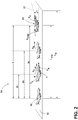
FIG. 2 is a schematic diagram of a takeoff sequence for the aircraft ofFIG. 1 . -
FIG. 3 is a schematic diagram of the flight management system for the aircraft ofFIG. 1 . -
FIG. 4 is a schematic diagram of an exemplary takeoff sequence check processed by the flight management system ofFIG. 3 . -
FIG. 5 is a flow chart for a method of analyzing the takeoff sequence ofFIG. 2 according to an aspect of the disclosure herein. - Aspects of the disclosure described herein are broadly directed to a method and apparatus for analyzing a takeoff sequence for an aircraft. For the purposes of illustration, one exemplary environment within which the takeoff sequence can be controlled will be described in the form of an aircraft management system. Such an aircraft management system can include a controller, processor, and memory. It will be understood, however, that aspects of the disclosure described herein are not so limited and can have general applicability within other aircraft systems.
- The takeoff sequence for an aircraft must factor in numerous variables, including but not limited to pressure altitude, wind, temperature, slip coefficient of the runway, and other weather and/or environmental factors. Variables associated with the aircraft, including but not limited to weight and balance should also be considered. Additionally other variables with respect to the runway, direction, incline, and length, also need to be factored into the takeoff sequence. It is vital to aircraft safety that the takeoff sequence considers all relevant factors and in the event problems are detected, enables the pilot to abort the takeoff sequence.
- As used herein, the term "upstream" refers to a direction that is opposite the fluid flow direction, and the term "downstream" refers to a direction that is in the same direction as the fluid flow. The term "fore" or "forward" means in front of something and "aft" or "rearward" means behind something. For example, when used in terms of fluid flow, fore/forward can mean upstream and aft/rearward can mean downstream.
- Additionally, as used herein, the terms "radial" or "radially" refer to a direction away from a common center. For example, in the overall context of a turbine engine, radial refers to a direction along a ray extending between a center longitudinal axis of the engine and an outer engine circumference. Furthermore, as used herein, the term "set" or a "set" of elements can be any number of elements, including only one.
- Additionally, as used herein, a "controller" or "controller module" can include a component configured or adapted to provide instruction, control, operation, or any form of communication for operable components to effect the operation thereof. A controller module can include any known processor, microcontroller, or logic device, including, but not limited to: field programmable gate arrays (FPGA), an application specific integrated circuit (ASIC), a full authority digital engine control (FADEC), a proportional controller (P), a proportional integral controller (PI), a proportional derivative controller (PD), a proportional integral derivative controller (PID controller), a hardware-accelerated logic controller (e.g. for encoding, decoding, transcoding, etc.), the like, or a combination thereof. Non-limiting examples of a controller module can be configured or adapted to run, operate, or otherwise execute program code to effect operational or functional outcomes, including carrying out various methods, functionality, processing tasks, calculations, comparisons, sensing or measuring of values, or the like, to enable or achieve the technical operations or operations described herein. The operation or functional outcomes can be based on one or more inputs, stored data values, sensed or measured values, true or false indications, or the like. While "program code" is described, non-limiting examples of operable or executable instruction sets can include routines, programs, objects, components, data structures, algorithms, etc., that have the technical effect of performing particular tasks or implement particular abstract data types. In another non-limiting example, a controller module can also include a data storage component accessible by the processor, including memory, whether transient, volatile or non-transient, or non-volatile memory. Additional non-limiting examples of the memory can include Random Access Memory (RAM), Read-Only Memory (ROM), flash memory, or one or more different types of portable electronic memory, such as discs, DVDs, CD-ROMs, flash drives, universal serial bus (USB) drives, the like, or any suitable combination of these types of memory. In one example, the program code can be stored within the memory in a machine-readable format accessible by the processor. Additionally, the memory can store various data, data types, sensed or measured data values, inputs, generated or processed data, or the like, accessible by the processor in providing instruction, control, or operation to effect a functional or operable outcome, as described herein.
- Additionally, as used herein, elements being "electrically connected," "electrically coupled," or "in signal communication" can include an electric transmission or signal being sent, received, or communicated to or from such connected or coupled elements. Furthermore, such electrical connections or couplings can include a wired or wireless connection, or a combination thereof.
- Also, as used herein, while sensors can be described as "sensing" or "measuring" a respective value, sensing or measuring can include determining a value indicative of or related to the respective value, rather than directly sensing or measuring the value itself. The sensed or measured values can further be provided to additional components. For instance, the value can be provided to a controller module or processor as defined above, and the controller module or processor can perform processing on the value to determine a representative value or an electrical characteristic representative of said value.
- All directional references (e.g., radial, axial, proximal, distal, upper, lower, upward, downward, left, right, lateral, front, back, top, bottom, above, below, vertical, horizontal, clockwise, counterclockwise, upstream, downstream, forward, aft, etc.) are used only for identification purposes to aid the reader's understanding of the present disclosure, and should not be construed as limiting, particularly as to the position, orientation, or use of aspects of the disclosure described herein. Connection references (e.g., attached, coupled, connected, and joined) are to be construed broadly and can include intermediate members between a collection of elements and relative movement between elements unless otherwise indicated. As such, connection references do not necessarily infer that two elements are directly connected and in fixed relation to one another. The exemplary drawings are for purposes of illustration only and the dimensions, positions, order and relative sizes reflected in the drawings attached hereto can vary.
-
FIG. 1 schematically illustrates anaircraft 10 including an aircraft flight management system (FMS) 12 for operating various aspects associated with the flight of theaircraft 10 including a takeoff sequence 24 (FIG.2 ). Theaircraft 10 can include, but is not limited to,slats 14,flaps 16,engines 18, andlanding gear 20, all of which contribute to thetakeoff sequence 24. The FMS 12 can be electronically coupled as illustrated in phantom to each of theslats 14,flaps 16,engines 18, andlanding gear 20 in any suitable manner, including hardwired or wirelessly. Theaircraft 10 can be a jet propelled and propeller driven aircraft, as are commonly employed throughout the aircraft industry. - Referring to
FIG. 2 , the departure of theaircraft 10 from anairport runway 22 is generally illustrated according to thetakeoff sequence 24. During takeoff or departure from theairport runway 22, theaircraft 10 accelerates with an acceleration (a), the acceleration can be at full power, or a derated thrust, with theaircraft flaps 16 set in a takeoff position to promote a lift (FL) to enable the aircraft lift off from the runway at an initial climb rate (pitch rate) along apath 27 and climb angle α. The aircraft flap 16 position is dependent on conditions making a small range of flap positions allowable for takeoff. More flaps can get the aircraft in the air sooner as more lift (FL) is generated but then the climb angle α will be shallower due to higher drag and lower excess thrust. A full flap position is typically not an option for takeoff as the extra lift (FL) added does not compensate for extra drag generated. The aircraft climb rate can vary depending upon size and weight of the aircraft, engine thrust, and atmospheric conditions such as temperature, wind, and other variables. - The
aircraft takeoff sequence 24 can occur over the course of a total takeoff time period (T) which can include aninitial time period 26, an activaterotation time period 28, and finally atakeoff time period 30. The acceleration (a) and the lift (FL) of theaircraft 10 can change or remain constant during thetakeoff sequence 24. An actual velocity (vA) can be determined at any given time during thetakeoff sequence 24 utilizing known methods described herein and is dependent on the acceleration (a) and the lift (FL). The actual velocity (vA) can also be referred to as a real-time velocity, or the velocity of theaircraft 10 in real time. - A
takeoff reference velocity 25 associated with the takeoff time period (T), theairport runway 22, and theaircraft 10 itself can be determined based on several factors described herein. While it is possible for thetakeoff reference velocity 25 to be equal to the actual velocity (vA), it should be understood that thetakeoff reference velocity 25 is associated with a calculated velocity based on variables received at theFMS 12, while the actual velocity (vA) is an actual velocity of the aircraft during thetakeoff sequence 24. - The
takeoff reference velocity 25 can be determined for each of theinitial time period 26, activaterotation time period 28, and thetakeoff time period 30. Thetakeoff reference velocity 25 associated with theinitial time period 26 can be a decision velocity (v1), the velocity at which theaircraft 10 can brake without overrunning therunway 22. The decision velocity (v1) means the maximum speed during takeoff at which the pilot must take a first action (e.g. apply brakes, reduce thrust, deploy speed brakes) to stop theaircraft 10 without overrunning therunway 22. Theinitial time period 26 is defined as the length of time for theaircraft 10 to accelerate from a velocity of 0m/s to the decision velocity (v1). - Another
takeoff reference velocity 25 associated with the activaterotation time period 28 can be a rotation velocity (vR), the velocity at which a rotation of theaircraft 10 is initiated toward thepath 27 along the angle α. The activaterotation time period 28 is defined as the length of time for theaircraft 10 to accelerate from 0m/s to the rotation velocity (vR). - The
takeoff reference velocity 25 associated with thetakeoff time period 30 can be a takeoff velocity (v2), the velocity at which theaircraft 10 can take off with oneengine 18 inoperative. In other words, the takeoff velocity (v2) can refer to the minimum speed during takeoff, following a failure of one engine, at which the pilot can continue the take-off and achieve the required height above the take-off surface without overrunning therunway 22. It is further contemplated that a minimum takeoff velocity (v2min) is a minimum takeoff safety speed, a velocity at which theaircraft 10 can take off safely with allengines 18 operating normally. Thetakeoff time period 30, is therefore defined as the length of time for theaircraft 10 to accelerate from 0m/s to the takeoff velocity (v2). - It is contemplated that the
initial time period 26, activaterotation time period 28 and thetakeoff time period 30 overlap to an extent. For example, theinitial time period 26 that theaircraft 10 takes to reach the decision velocity (v1) can be 9 seconds where theaircraft 10 can reach the takeoff velocity (v2) in 7 seconds. In other words, in implementation an aircraft could take off from a long runway where even when it reaches the takeoff velocity (v2), there is still sufficient length to apply the brakes and stop at the end of the runway. It is further contemplated that the takeoff velocity (v2) and the rotation velocity (vR), are the same making the activaterotation time period 28 and thetakeoff time period 30 the same as well. - A minimum length (Lmin) associated with the takeoff velocity (v2) is illustrated as less than the runway length (LR), though it is contemplated that the minimum length (Lmin) is equal to the runway length (LR). It should be understood that the minimum length (Lmin) required to achieved each
takeoff reference velocity 25 can be the same, or different depending on several variables described in more detail herein. By way of non-limiting example, the weather conditions can significantly change a slip coefficient (µ) between therunway 22 and thelanding gear 20 which can increase the minimum length (Lmin) required for the takeoff velocity (v2). - Turning to
FIG. 3 , anexemplary FMS 12 is illustrated in detail. TheFMS 12 is configured to receive selected flight parameters to control the flight of theaircraft 10. TheFMS 12 includes an FMSonboard computer processor 40 and amemory 42. Thememory 42 includes a storednavigation database 44 that stores aircraft navigation information. Theonboard computer processor 40 receives various inputs including sensedaircraft altitude 46, sensedaircraft speed 48, and sensedair temperature 50 from anair data computer 52. Additionally, theonboard computer processor 40 receives inputs fromnavigation sensors 54, such as location coordinates from a global positioning system (GPS) 56 and inertial data frominertial sensors 58. Further, theonboard computer processor 40 receives other inputs from other sensors such asfuel quantity 60, and other sensed variables known in the art. - The sensed
aircraft altitude 46, sensedaircraft speed 48, and sensedair temperature 50 can all be generally referred to as real-time aircraft variables 62. Additional real-time aircraft variables 62 includepassenger count 64 andbaggage amount 66 which can together influence atotal weight 68 of the aircraft. An engine status/thrust 70 and aflap orientation 72 can also be included in the real-time aircraft variables 62 that are received by theonboard computer processor 40. - The
onboard computer processor 40 is further shown in communication with a control and display unit (CDU) 74 having adisplay 76. It should be appreciated that theCDU 74 can be a human machine interface that allows pilots to input data and to receive output data. For example, output data indicating computedparameter velocities 25 can be provided in display pages presented on thedisplay 76 to allow a pilot of the aircraft to operate the aircraft pursuant to the output data provided by theFMS 12. - The
FMS 12 is further shown to include athrottle control 78 for controlling the engine throttle, as should be evident to those skilled in the art. Thethrottle control 78 can be manually actuated by a pilot of the aircraft in a manual mode. In an automatic flight control mode, thethrottle control 78 can be automatically controlled by anauto throttle signal 80 provided by theonboard computer processor 40. It should be appreciated that theonboard computer processor 40 can output command signals for controlling the aircraft with the computed throttle value by providing output commands via thedisplay 76 or by automatically controlling thethrottle control 78 via theauto throttle signal 80. - In operation, real-
time condition variables 82 are received by theonboard computer processor 40. It is further contemplated that the real-time condition variables 82 can be stored in thememory 42, by way of non-limiting example in an aircraft performance table 84 for reference on similar or the same routes. The real-time condition variables 82 can include, but are not limited to,pressure 86,weather 88, andwind 90 conditions. -
Runway information 92 is also a variable that can be stored in thememory 42 and updated.Runway information 92, can include, but is not limited to,length 94, the runway length (LR) described herein, slip coefficient (µ) values 96 associated with various runways given the real-time condition variables 82,runway elevation 97 associated with the geographical location of therunway 22, and the presence of an Engineered Material Arresting System (EMAS) 98 that are crushable concrete blocks past the end of therunway 22 and used to catch aircraft with minimal damage. - The
FMS 12 illustrated is a flight management system that can be configured to perform various aspects to control an aircraft during aircraft departure, cruising and arrival procedures. It should be appreciated that thememory 42 and the storednavigation database 44 can include an existing navigation database in an existing flight management system that is upgraded to perform thetakeoff sequence 24 described herein. - Turning to
FIG. 4 , an exemplary takeoff sequence check 100 processed by theFMS 12 is illustrated. Each of the checks described herein can result in a yes/no output. A yes output can always result in a continuation of thetakeoff sequence 24 while a no output can result in a variety of processes including aborting thetakeoff sequence 24. It should be understood that aborting thetakeoff sequence 24 can occur manually. It is further contemplated that aborting the takeoff sequence can occur automatically as initiated by the FMS at any safe stage or as a configurable value, i.e. at a fixed velocity or at a percentage of v1, vR, or v2. The FMS can be configured to radio the air traffic control (ATC) with a message that takeoff is aborted so that ATC can ensure no other aircraft use the runway. - At the beginning of the takeoff time period (T), an
initial check 102 can occur to determine if (Lmin≥LR). This initial check determines whether theaircraft 10 is capable of taking off from therunway 22 on which it is situated. While depicted as a check executed by theFMS 12, it should be understood that this can also be a check complete long before the aircraft even approaches therunway 22. Along with aborting thetakeoff sequence 24 it is also contemplated that if the output is no, the thrust can increase, increasing acceleration (a), and thetakeoff sequence 24 can continue. It should be understood that thrust calculations up to and including maximum thrust can be completed to determine if thetakeoff sequence 24 can continue. - After the
initial time period 26 is complete, an initial time period check 104 can occur to determine if (vA≥v1), is the actual velocity (vA) greater than or at least equal to the decision velocity (v1) described herein. Again, it is contemplated that if no, the thrust can increase, and that thrust calculations up to and including maximum thrust can be completed to determine if thetakeoff sequence 24 can continue. In the even the takeoff sequence can continue, increasing acceleration (a), and thetakeoff sequence 24 continues. - After the activate
rotation time period 28 is complete, a rotation time period check 106 can occur to determine if (vA≥vR), is the actual velocity (vA) greater than or at least equal to the rotation velocity (vR) described herein. At this check, if no, the initial time period check 104 can be processed again. Also, if no, the thrust can increase, and that thrust calculations up to and including maximum thrust can be completed to determine if thetakeoff sequence 24 can continue. If yes, thetakeoff sequence 24 can be continued and theaircraft 10 can initiate rotation toward the climb angle α. It is further contemplated that increasing acceleration (a) can also occur, and thetakeoff sequence 24 continues. - After the
takeoff time period 30 is complete, a takeoff time period check 108 can occur to determine if (vA ≥ v2), is the actual velocity (vA) greater than or at least equal to the takeoff velocity (v2) described herein. At this check, if no, the initialtime period check 104 and/or the activate rotation time period check 106 can be recalculated or thetakeoff sequence 24 can be aborted. It is also contemplated that if no, the thrust can increase, and that thrust calculations up to and including maximum thrust can be completed to determine if thetakeoff sequence 24 can continue. At this particular point, rotation of the aircraft to the climb angle α in order to takeoff should be completed. If yes, thetakeoff sequence 24 can be continued and theaircraft 10 can takeoff. -
FIG. 5 is a flow chart illustrating amethod 200 of real-time analyzing, with the FMS, thetakeoff sequence 24 for theaircraft 10 on apredetermined runway 22. It should be understood thatrunway information 92 associated with therunway 22 from which theaircraft 10 will depart can be received and stored at thememory 42 or directly input into theonboard computer processor 40 via theCDU 74. - At 202 the FMS receives real-time data corresponding to variables that influence the
takeoff reference velocity 25 of theaircraft 10 during thetakeoff sequence 24.. The variables can be, by way of non-limiting example, the real-time aircraft variables 62 and real-time condition variables 82 described herein, and can be input manually via theCDU 74 or sensed and directly processed by theonboard computer processor 40, or stored in thememory 42. Calculating thetakeoff reference velocity 25 associated with the receivedrunway information 92 and the receivedvariables - At 204 real-time data corresponding to the actual velocity (vA) and acceleration (a) of the aircraft is received at the
FMS 12. Upon initiating thetakeoff sequence 24, the actual velocity (vA) associated with a current speed of theaircraft 10 can be determined. Theonboard computer processor 40 receives various inputs including the sensedaircraft speed 48 which can be utilized to determine the actual velocity (vA). - It should be understood that receiving and calculating the information, variables, and/or takeoff reference velocities can include manually inputting, sensing, or any combination of manually inputting and sensing where the data collected is eventually processed by the
onboard computer processor 40. Received and calculated information can change quickly in certain weather conditions. A benefit associated with the disclosure herein is that by using sensors, the aircraft determines actual data in real-time, avoiding any mistakes made when transferring or inputting of information. It should be understood that as described herein velocity includes both the speed and direction of theaircraft 10, and at any time the data received associated with the actual velocity (vA) can be either one of a speed value or direction value or both. Data received associated with thetakeoff reference velocity 25 can also be a speed value, direction value, both, or other pieces of information including but not limited to the aircraft and real-time condition variables. - A final estimated velocity (vf) based on the actual velocity (vA) and the acceleration (a) is estimated at 206. The final estimated velocity (vf) can be any velocity occurring in the future of the
takeoff sequence 24. By way of non-limiting example the final estimated velocity (vf) can be a calculated value for the takeoff velocity (v2) with which the aircraft will depart based on the actual velocity (vA) and the additional variables received. It is further contemplated that the final estimated velocity (vf) is a calculated value for the decision velocity (vi) or the rotation velocity (vR). - At 208 the final estimated velocity (vf) is compared to the
takeoff reference velocity 25 to determine if the final estimatedvelocity 25 is within a predetermined range of thetakeoff reference velocity 25. The predetermined range is determined based on theaircraft 10 capabilities and can be different for different aircraft. It should be understood that the final estimated velocity (vf) can be a calculated value based on real-time data collected while thetakeoff reference velocity 25 can be a calculated value for what a value of the actual velocity should be at any given time based on the received variables. In other words, the final estimated velocity (vf) is the most likely outcome for theaircraft 10 in real time while thetakeoff reference velocity 25 is how the aircraft should operate based on the received variables. In this manner, when a takeoff sequence is undergoing a smooth execution, a comparison of the final estimated velocity (vf) to thetakeoff reference velocity 25 would indicate similar if not matching values. However in a scenario in which the final estimated velocity (vf) is much different than thetakeoff reference velocity 25, or outside the predetermined range, a pilot could be alerted and thetakeoff sequence 24 could be aborted as previously described herein. Therefore at 210, in the event comparing indicates that the final estimated velocity (vf) is not within the predetermined range, at least one operational variable is altered. By way of non-limiting example, altering at least one operational variable can include increasing thrust, adjusting a flap mounted to the aircraft, or adjusting a slat mounted to the aircraft. It is also contemplated that a signal that alerts the pilot to manually abort the takeoff can be sent to thedisplay 76. - In the event the final estimated velocity (vf) is within the predetermined range of the takeoff reference velocity 25 a signal that alerts the pilot that everything has checked out and the
takeoff sequence 24 can continue can be sent to thedisplay 76. - The
method 200 can include aborting the takeoff sequence in an event where the actual velocity is outside the predetermined range of thetakeoff reference velocity 25 as described inFIG. 4 . Themethod 200 can further include recalculating thetakeoff reference velocity 25 based on updated variables in an event where the actual velocity (vA) is outside the predetermined range of the takeoff reference velocity. As previously described herein, upon recalculation, themethod 200 can include increasing the thrust in an event where the recalculatedtakeoff reference velocity 25 indicates an increase in thrust will bring the actual velocity (vA) within the predetermined range of thetakeoff reference velocity 25. It is further contemplated that themethod 200 can include monitoring the lift (FL) during thetakeoff sequence 24 and in an event where the recalculatedtakeoff reference velocity 25 indicates that adjusting theslat 14 or theflap 16 mounted to theaircraft 10 will bring the actual velocity (vA) within the predetermined range of thetakeoff reference velocity 25, adjusting theslats 14 and/or theflaps 16. - The
method 200 as described herein can include calculating an optimal takeoff sequence based on the real-time aircraft variables 62, real-time condition variables 82, andrunway information 92. The optimal takeoff sequence can include which combination ofthrust 70,slat 14, andflap 16 settings providesoptimal fuel 60 consumption and noise levels while retaining safety of takeoff within therunway length 94 and climb requirements associated with the airport from which the aircraft is departing. - The
method 200 can further include verifying that the takeoff sequence is within a predetermined parameter associated with the optimal takeoff sequence. The predetermined parameter can be thereference velocities 25 described herein. Verification can occur by determining during thetakeoff sequence 24 if the acceleration (a) values received during monitoring result in any one of the calculated decision velocity (v1), rotation velocity (vR), and/or the takeoff velocity (v2) described herein. In an event where aweight 68 or slip coefficient (µ) has been miscalculated, the verification process can produce a signal or alert that the real-time takeoff sequence is not within the predetermined parameter associated with the optimal takeoff sequence. - If acceleration (a) is lower than a calculated acceleration required for the optimal takeoff sequence, a recalculation can occur to determined if the runway length (LR) is sufficient with a current thrust. If so, recalculations based on the runway length (LR) can occur. If not, more thrust can be applied and if with maximum thrust the actual velocity (vA) cannot be reached (vA ≥v1) the
takeoff sequence 24 is aborted. The recalculation can either be displayed to a pilot to input a new thrust and/or automatically applied, with or without thedisplay 76 indicating an update. - Determining if the
EMAS 98 is present on therunway 22 can also be a further consideration. Because many airports include theEMAS 98 and theFMS 12 could include an update that sends a query to an airport/navigation database regarding whether the airport has such a system. In the event theEMAS 98 is present, aborting takeoff can be allowed/suggested even after passing v1 by a calculated amount in a situation where risking a usual takeoff and immediate landing procedure is less desirable than an intentional overrun of the runway. - The
method 200 can include sending a signal to indicate when the actual velocity (vA) is equal to thetakeoff reference velocity 25. This signal could be in the form of automatically annunciating the actual velocity (vA) when equal to any one of the takeoff reference velocities (v1, vR and v2). In two pilot operated aircraft, a monitoring pilot conducts calculations prior to takeoff and tracks speed and calls the speeds out to a flying pilot, i.e. "VI" when the aircraft has reached (v1). TheFMS 12 as described herein can automatically calculate and recalculate thetakeoff reference velocities 25 and performs the monitoring by calling out the speeds. It is also contemplated that the speeds are displayed or called out or both. This feature would reduce workload for the monitoring pilot to concentrate on other tasks and could also enable future single pilot operations where theFMS 12 acts as the monitoring pilot. - It should be understood that any combination of the methods and check sequences described herein is contemplated. The flight management system as described automatically verifies, or can even replace, pilot calculations based on measurements of various systems and information provided over datalinks. The flight management system is capable of checking that the aircraft is in the correct configuration. During the takeoff sequence, the system monitors performance against expectation in the calculation and is capable of recalculating to decide if a higher thrust allows safe takeoff or if the takeoff sequence needs to be aborted.
- Takeoff sequencing is a complex problem as weather/environment factors need to be considered (altitude, wind, temperature, slip coefficient of runway) as well as aircraft weight and balance and tested against runway parameters (direction, incline, length). Benefits associated with the methods and apparatus described herein include consideration of the flap and thrust settings as well as the decision, control, and takeoff velocities speed. Because errors in calculation can result in failure, it is vital to automate the calculations with as many variable input considerations as possible. Pilots can make calculation errors based on false assumptions (weight and balance wrong, slip coefficient wrong) or configuration settings (thrust or flap settings incorrect). For fuel saving, engine life, and noise abatement, maximum thrust is not normally applied during a takeoff sequence and instead an "optimal thrust profile" is applied. If a pilot detects problems too late in the takeoff sequence, the pilot may not be able to simply select maximum thrust and continue safe takeoff. The system described herein provides at least an automated check for the pilot. It is also contemplated that the flight management system described herein automatically increases thrust in an event where the real-time takeoff sequence is not within the predetermined parameter associated with the optimal takeoff sequence.
- To the extent not already described, the different features and structures of the various aspects can be used in combination, or in substitution with each other as desired. That one feature is not illustrated in all of the examples is not meant to be construed that it cannot be so illustrated, but is done for brevity of description. Thus, the various features of the different aspects can be mixed and matched as desired to form new aspects, whether or not the new aspects are expressly described. All combinations or permutations of features described herein are covered by this disclosure.
- This written description uses examples to describe aspects of the disclosure described herein, including the best mode, and also to enable any person skilled in the art to practice aspects of the disclosure, including making and using any devices or systems and performing any incorporated methods. The patentable scope of aspects of the disclosure is defined by the claims, and can include other examples that occur to those skilled in the art. Such other examples are intended to be within the scope of the claims if they have structural elements that do not differ from the literal language of the claims, or if they include equivalent structural elements with insubstantial differences from the literal languages of the claims.
- Further aspects of the invention are provided by the subject matter of the following clauses:
- 1. A method of real-time analyzing, with a flight management systems (FMS) of an aircraft, a takeoff sequence of the aircraft on a predetermined runway, the method comprising receiving at the FMS, from sensors on the aircraft, real-time data corresponding to at least one variable influencing a takeoff reference velocity of the aircraft during the takeoff sequence, receiving at the FMS, from sensors on the aircraft, real-time data of an actual velocity of the aircraft and a real-time acceleration of the aircraft, estimating, with the FMS, a final estimated velocity based on the actual velocity and the real-time acceleration, comparing, with the FMS, the final estimated velocity to the takeoff reference velocity to determine if the final estimated velocity is within a predetermined range of the takeoff reference velocity; and altering, with the FMS, at least one operational variable of the aircraft when the comparing indicates the final estimated velocity is not within the predetermined range.
- 2. The method of any of the preceding clauses, further comprising calculating the takeoff reference velocity with the FMS.
- 3. The method of any of the preceding clauses, wherein calculating the takeoff reference velocity comprises determining a decision velocity associated with a velocity at which the aircraft is capable of braking without overrunning the predetermined runway.
- 4. The method of any of the preceding clauses, wherein calculating a takeoff reference velocity comprises determining a rotation velocity associated with a velocity at which the aircraft is rotated for takeoff.
- 5. The method of any of the preceding clauses, wherein calculating the takeoff reference velocity comprises determining a takeoff velocity associated with a velocity to ensure lift of the aircraft from the predetermined runway.
- 6. The method of any of the preceding clauses, wherein receiving real-time data corresponding to at least one variable influencing a takeoff reference velocity of the aircraft during the takeoff sequence comprises receiving real-time aircraft variables and real-time condition variables.
- 7. The method of any of the preceding clauses, further comprising storing the real-time aircraft variables as at least one of a weight value, balance value, pressure altitude value, temperature value, and flap/slat configuration value.
- 8. The method of any of the preceding clauses, further comprising storing the real-time condition variables as at least one of a runway coefficient, wind speed, wind direction, temperature value, and pressure value.
- 9. The method of any of the preceding clauses, further comprising aborting the takeoff sequence in an event where the actual velocity is outside the predetermined range of the takeoff reference velocity.
- 10. The method of any of the preceding clauses, further comprising recalculating the takeoff reference velocity based on updated variables in an event where the actual velocity is outside the predetermined range of the takeoff reference velocity.
- 11. The method of any of the preceding clauses, wherein altering at least one operational variable of the aircraft when the comparing indicates the final estimated velocity is not within the predetermined range comprises at least one of increasing thrust, adjusting a flap mounted to the aircraft, or adjusting a slat mounted to the aircraft.
- 12. The method of any of the preceding clauses, further comprising processing a takeoff sequence check.
- 13. The method of any of the preceding clauses, further comprising calculating an optimal take off sequence.
- 14. The method of any of the preceding clauses, further comprising determining if an Engineered Material Arresting System is present on the predetermined runway.
- 15. The method of any of the preceding clauses, wherein the FMS sends a signal indicating when the actual velocity is equal to the takeoff reference velocity.
- 16. An aircraft flight management system configured to analyze a takeoff sequence for an aircraft, the aircraft flight management system comprising memory storing runway information associated with the runway from which the aircraft will depart, one or more inputs configured to receive variables comprising real-time aircraft variables and real-time condition variables that influence an actual velocity of the aircraft, sensors for sensing the actual velocity of the aircraft, and a processor configured to calculate a takeoff reference velocity associated with the runway information, the real-time aircraft variables, and the real-time condition variables, calculate a real-time takeoff value associated with the actual velocity and the runway information, calculate a takeoff requirement value associated with the takeoff reference velocity; and compare the real-time takeoff value to the takeoff requirement value.
- 17. The aircraft flight management system of any of the preceding clauses further comprising a control and display unit.
- 18. The aircraft flight management system of any of the preceding clauses further comprising a throttle control.
- 19. The aircraft flight management system of any of the preceding clauses wherein the sensors include an inertial sensor.
- 20. The aircraft flight management system of any of the preceding clauses further comprising aircraft at least one of or both flaps and slats mounted to the aircraft.
Claims (15)
- A method (200) of real-time analyzing, with a flight management systems (FMS) (12) of an aircraft (10), a takeoff sequence of the aircraft (10) on a predetermined runway (22), the method comprising:receiving (202) at the FMS (12), from sensors (54, 58) on the aircraft (10), real-time data corresponding to at least one variable influencing a takeoff reference velocity (25) of the aircraft (10) during the takeoff sequence (24);receiving (204) at the FMS (12), from sensors (54, 58) on the aircraft (10), real-time data of an actual velocity (VA) of the aircraft (10) and a real-time acceleration (a) of the aircraft (10);estimating (206), with the FMS (12), a final estimated velocity (VF) based on the actual velocity (VA) and the real-time acceleration (a);comparing (208), with the FMS (12), the final estimated velocity (VF) to the takeoff reference velocity (25) to determine if the final estimated velocity (VF) is within a predetermined range of the takeoff reference velocity (25); andaltering (210), with the FMS (12), at least one operational variable of the aircraft (10) when the comparing indicates the final estimated velocity (VF) is not within the predetermined range.
- The method (200) of claim 1, further comprising calculating the takeoff reference velocity (25) with the FMS (12).
- The method (200) of claim 2, wherein calculating the takeoff reference velocity (25) comprises determining a decision velocity (VI) associated with a velocity at which the aircraft (10) is capable of braking without overrunning the predetermined runway (22).
- The method (200) of claim 2 or 3, wherein calculating a takeoff reference velocity (25) comprises determining a rotation velocity (VR) associated with a velocity at which the aircraft (10) is rotated for takeoff.
- The method (200) of any of claims 2 to 4, wherein calculating the takeoff reference velocity (25) comprises determining a takeoff velocity (V2) associated with a velocity to ensure lift of the aircraft (10) from the predetermined runway.
- The method (200) of any of claims 1 to 5, wherein receiving real-time data corresponding to at least one variable influencing a takeoff reference velocity (25) of the aircraft (10) during the takeoff sequence (24) comprises receiving real-time aircraft variables (62) and real-time condition variables (82).
- The method (200) of claim 6, further comprising storing the real-time aircraft variables (62) as at least one of a weight value, balance value, pressure altitude value, temperature value, and flap/slat configuration value.
- The method (200) of claim 6 or 7, further comprising storing the real-time condition variables (82) as at least one of a runway coefficient, wind speed, wind direction, temperature value, and pressure value.
- The method (200) of any of claims 1 to 8, further comprising aborting the takeoff sequence (24) in an event where the actual velocity (VA) is outside the predetermined range of the takeoff reference velocity (25).
- The method (200) of any of claims 1 to 9, further comprising recalculating the takeoff reference velocity (25) based on updated variables in an event where the actual velocity (VA) is outside the predetermined range of the takeoff reference velocity (25).
- The method (200) of any of claims 1 to 10, wherein altering (210) at least one operational variable of the aircraft (10) when the comparing indicates the final estimated velocity (VF) is not within the predetermined range comprises at least one of increasing thrust, adjusting a flap mounted to the aircraft, or adjusting a slat mounted to the aircraft.
- The method (200) of any of claims 1 to 11, further comprising processing a takeoff sequence check.
- The method (200) of any of claims 1 to 12, further comprising calculating an optimal take off sequence.
- The method (200) of any of claims 1 to 13, further comprising determining if an Engineered Material Arresting System is present on the predetermined runway (22).
- The method (200) of any of claims 1 to 14, wherein the FMS (12) sends a signal indicating when the actual velocity (VA) is equal to the takeoff reference velocity (25).
Applications Claiming Priority (1)
| Application Number | Priority Date | Filing Date | Title |
|---|---|---|---|
| US16/692,242 US11837099B2 (en) | 2019-11-22 | 2019-11-22 | Aircraft flight management system |
Publications (2)
| Publication Number | Publication Date |
|---|---|
| EP3825983A1 true EP3825983A1 (en) | 2021-05-26 |
| EP3825983B1 EP3825983B1 (en) | 2025-04-02 |
Family
ID=73043107
Family Applications (1)
| Application Number | Title | Priority Date | Filing Date |
|---|---|---|---|
| EP20205012.6A Active EP3825983B1 (en) | 2019-11-22 | 2020-10-30 | Aircraft flight management system |
Country Status (3)
| Country | Link |
|---|---|
| US (1) | US11837099B2 (en) |
| EP (1) | EP3825983B1 (en) |
| CN (1) | CN112835379B (en) |
Families Citing this family (6)
| Publication number | Priority date | Publication date | Assignee | Title |
|---|---|---|---|---|
| US20220024601A1 (en) * | 2020-07-23 | 2022-01-27 | Gulfstream Aerospace Corporation | Controllers and aircraft with variable engine thrust takeoff system |
| GB2604183A (en) * | 2021-02-26 | 2022-08-31 | Airbus Operations Ltd | Aircraft system |
| US20230166857A1 (en) * | 2021-11-29 | 2023-06-01 | Raytheon Technologies Corporation | Final takeoff speed determination for an aircraft |
| US11846944B2 (en) * | 2022-02-09 | 2023-12-19 | The Boeing Company | Takeoff performance alert |
| US12135549B2 (en) * | 2022-02-10 | 2024-11-05 | General Electric Company | Systems and methods for providing information regarding particulate matter within an aircraft engine |
| CN115817833A (en) * | 2022-09-07 | 2023-03-21 | 中国商用飞机有限责任公司 | Speed target value warning and control method and device, storage medium and aircraft |
Citations (3)
| Publication number | Priority date | Publication date | Assignee | Title |
|---|---|---|---|---|
| US10202204B1 (en) * | 2016-03-25 | 2019-02-12 | AAR Aerospace Consulting, LLC | Aircraft-runway total energy measurement, monitoring, managing, safety, and control system and method |
| US20190072982A1 (en) * | 2017-09-07 | 2019-03-07 | Embraer S.A. | Safe takeoff system |
| US20190354644A1 (en) * | 2018-05-18 | 2019-11-21 | Honeywell International Inc. | Apparatuses and methods for detecting anomalous aircraft behavior using machine learning applications |
Family Cites Families (11)
| Publication number | Priority date | Publication date | Assignee | Title |
|---|---|---|---|---|
| US20110040431A1 (en) | 2009-08-11 | 2011-02-17 | Honeywell International Inc. | Automated take off control system and method |
| US9058742B2 (en) * | 2013-02-12 | 2015-06-16 | Ge Aviation Systems, Llc | Methods for illustrating aircraft situational information |
| FR3031811A1 (en) * | 2015-01-15 | 2016-07-22 | Airbus Helicopters | METHOD AND DEVICE FOR DETERMINING THE WIND SPEED TO BE TAKEN INTO ACCOUNT IN ORDER TO OPTIMIZE THE MASS AT THE TAKE-OFF OF AN AIRCRAFT |
| CN105096663B (en) | 2015-08-04 | 2018-02-16 | 中国商用飞机有限责任公司 | Automatic takeoff and approach reference system and method |
| US10293951B2 (en) | 2016-03-17 | 2019-05-21 | United Technologies Corporation | Takeoff power management system and method for gas turbine engines |
| US9696724B1 (en) | 2016-04-22 | 2017-07-04 | Rockwell Collins, Inc. | Takeoff automating system, device, and method |
| FR3052251B1 (en) | 2016-06-03 | 2018-05-18 | Airbus Operations (S.A.S.) | METHOD FOR OPTIMIZING THE TAKE-OFF PARAMETERS OF AN AIRCRAFT |
| US10345824B2 (en) | 2016-09-02 | 2019-07-09 | The Boeing Company | Optimum cruise climb tracking for reduced fuel consumption using vertical and lateral navigation |
| US11226639B2 (en) | 2016-09-23 | 2022-01-18 | Yaborã Indústria Aeronáutica S.A. | Enhanced take-off system |
| US10399689B2 (en) | 2017-06-07 | 2019-09-03 | Ge Aviation Systems Llc | Optimizing aircraft control based on noise abatement volumes |
| CN108008736B (en) * | 2017-11-21 | 2020-12-01 | 山东科技大学 | Aircraft cooperative control method, device, computer-readable storage medium and terminal |
-
2019
- 2019-11-22 US US16/692,242 patent/US11837099B2/en active Active
-
2020
- 2020-10-30 EP EP20205012.6A patent/EP3825983B1/en active Active
- 2020-11-20 CN CN202011310263.4A patent/CN112835379B/en active Active
Patent Citations (3)
| Publication number | Priority date | Publication date | Assignee | Title |
|---|---|---|---|---|
| US10202204B1 (en) * | 2016-03-25 | 2019-02-12 | AAR Aerospace Consulting, LLC | Aircraft-runway total energy measurement, monitoring, managing, safety, and control system and method |
| US20190072982A1 (en) * | 2017-09-07 | 2019-03-07 | Embraer S.A. | Safe takeoff system |
| US20190354644A1 (en) * | 2018-05-18 | 2019-11-21 | Honeywell International Inc. | Apparatuses and methods for detecting anomalous aircraft behavior using machine learning applications |
Also Published As
| Publication number | Publication date |
|---|---|
| EP3825983B1 (en) | 2025-04-02 |
| US20210158709A1 (en) | 2021-05-27 |
| US11837099B2 (en) | 2023-12-05 |
| CN112835379A (en) | 2021-05-25 |
| CN112835379B (en) | 2024-08-02 |
Similar Documents
| Publication | Publication Date | Title |
|---|---|---|
| EP3825983B1 (en) | Aircraft flight management system | |
| US8670881B2 (en) | Flight management system for generating variable thrust cutback during aircraft departure | |
| EP2149075B1 (en) | Method of generating variable thrust cutback during aircraft departure | |
| EP2980774A1 (en) | Systems and methods for averting overweight aircraft landing circumstances | |
| EP3453623B1 (en) | Safe takeoff system | |
| US8428795B2 (en) | Method and system for predicting the possibility of complete stoppage of an aircraft on a landing runway | |
| US8380372B2 (en) | Process for verifying the coherence between aircraft take-off parameters and an available runway length | |
| EP2081826B1 (en) | Methods and systems for implementing location based noise abatement procedures | |
| US10112722B2 (en) | Power control for propeller-driven aircraft | |
| CN106971632A (en) | The aircraft relevant with energy management shows system | |
| CA2916118A1 (en) | Method for diagnosing a horizontal stabilizer fault | |
| US20160231137A1 (en) | System and Method for Providing Guidance During a Flare Maneuver of an Aircraft | |
| EP3677513A1 (en) | Aircraft airspeed system and method of cross checking airspeed | |
| US20220380020A1 (en) | Method for assisting the piloting of a rotorcraft comprising at least two engines | |
| US12154444B2 (en) | Systems and methods for enhanced situational awareness and auto TOGA | |
| EP4082917A1 (en) | Systems and methods for enhanced situational awareness and auto toga | |
| US20230166857A1 (en) | Final takeoff speed determination for an aircraft | |
| US20260004668A1 (en) | Aircraft tail strike detection and prevention system and method |
Legal Events
| Date | Code | Title | Description |
|---|---|---|---|
| PUAI | Public reference made under article 153(3) epc to a published international application that has entered the european phase |
Free format text: ORIGINAL CODE: 0009012 |
|
| STAA | Information on the status of an ep patent application or granted ep patent |
Free format text: STATUS: THE APPLICATION HAS BEEN PUBLISHED |
|
| AK | Designated contracting states |
Kind code of ref document: A1 Designated state(s): AL AT BE BG CH CY CZ DE DK EE ES FI FR GB GR HR HU IE IS IT LI LT LU LV MC MK MT NL NO PL PT RO RS SE SI SK SM TR |
|
| STAA | Information on the status of an ep patent application or granted ep patent |
Free format text: STATUS: REQUEST FOR EXAMINATION WAS MADE |
|
| 17P | Request for examination filed |
Effective date: 20211111 |
|
| RBV | Designated contracting states (corrected) |
Designated state(s): AL AT BE BG CH CY CZ DE DK EE ES FI FR GB GR HR HU IE IS IT LI LT LU LV MC MK MT NL NO PL PT RO RS SE SI SK SM TR |
|
| STAA | Information on the status of an ep patent application or granted ep patent |
Free format text: STATUS: EXAMINATION IS IN PROGRESS |
|
| 17Q | First examination report despatched |
Effective date: 20240126 |
|
| GRAP | Despatch of communication of intention to grant a patent |
Free format text: ORIGINAL CODE: EPIDOSNIGR1 |
|
| STAA | Information on the status of an ep patent application or granted ep patent |
Free format text: STATUS: GRANT OF PATENT IS INTENDED |
|
| INTG | Intention to grant announced |
Effective date: 20241030 |
|
| GRAS | Grant fee paid |
Free format text: ORIGINAL CODE: EPIDOSNIGR3 |
|
| GRAA | (expected) grant |
Free format text: ORIGINAL CODE: 0009210 |
|
| STAA | Information on the status of an ep patent application or granted ep patent |
Free format text: STATUS: THE PATENT HAS BEEN GRANTED |
|
| AK | Designated contracting states |
Kind code of ref document: B1 Designated state(s): AL AT BE BG CH CY CZ DE DK EE ES FI FR GB GR HR HU IE IS IT LI LT LU LV MC MK MT NL NO PL PT RO RS SE SI SK SM TR |
|
| REG | Reference to a national code |
Ref country code: GB Ref legal event code: FG4D |
|
| REG | Reference to a national code |
Ref country code: CH Ref legal event code: EP |
|
| REG | Reference to a national code |
Ref country code: DE Ref legal event code: R096 Ref document number: 602020048637 Country of ref document: DE |
|
| REG | Reference to a national code |
Ref country code: IE Ref legal event code: FG4D |
|
| P01 | Opt-out of the competence of the unified patent court (upc) registered |
Free format text: CASE NUMBER: APP_14196/2025 Effective date: 20250324 |
|
| REG | Reference to a national code |
Ref country code: NL Ref legal event code: MP Effective date: 20250402 |
|
| PG25 | Lapsed in a contracting state [announced via postgrant information from national office to epo] |
Ref country code: NL Free format text: LAPSE BECAUSE OF FAILURE TO SUBMIT A TRANSLATION OF THE DESCRIPTION OR TO PAY THE FEE WITHIN THE PRESCRIBED TIME-LIMIT Effective date: 20250402 |
|
| REG | Reference to a national code |
Ref country code: AT Ref legal event code: MK05 Ref document number: 1782091 Country of ref document: AT Kind code of ref document: T Effective date: 20250402 |
|
| PG25 | Lapsed in a contracting state [announced via postgrant information from national office to epo] |
Ref country code: FI Free format text: LAPSE BECAUSE OF FAILURE TO SUBMIT A TRANSLATION OF THE DESCRIPTION OR TO PAY THE FEE WITHIN THE PRESCRIBED TIME-LIMIT Effective date: 20250402 Ref country code: ES Free format text: LAPSE BECAUSE OF FAILURE TO SUBMIT A TRANSLATION OF THE DESCRIPTION OR TO PAY THE FEE WITHIN THE PRESCRIBED TIME-LIMIT Effective date: 20250402 Ref country code: PT Free format text: LAPSE BECAUSE OF FAILURE TO SUBMIT A TRANSLATION OF THE DESCRIPTION OR TO PAY THE FEE WITHIN THE PRESCRIBED TIME-LIMIT Effective date: 20250804 |
|
| REG | Reference to a national code |
Ref country code: LT Ref legal event code: MG9D |
|
| PG25 | Lapsed in a contracting state [announced via postgrant information from national office to epo] |
Ref country code: NO Free format text: LAPSE BECAUSE OF FAILURE TO SUBMIT A TRANSLATION OF THE DESCRIPTION OR TO PAY THE FEE WITHIN THE PRESCRIBED TIME-LIMIT Effective date: 20250702 Ref country code: GR Free format text: LAPSE BECAUSE OF FAILURE TO SUBMIT A TRANSLATION OF THE DESCRIPTION OR TO PAY THE FEE WITHIN THE PRESCRIBED TIME-LIMIT Effective date: 20250703 |
|
| PG25 | Lapsed in a contracting state [announced via postgrant information from national office to epo] |
Ref country code: PL Free format text: LAPSE BECAUSE OF FAILURE TO SUBMIT A TRANSLATION OF THE DESCRIPTION OR TO PAY THE FEE WITHIN THE PRESCRIBED TIME-LIMIT Effective date: 20250402 |
|
| PG25 | Lapsed in a contracting state [announced via postgrant information from national office to epo] |
Ref country code: BG Free format text: LAPSE BECAUSE OF FAILURE TO SUBMIT A TRANSLATION OF THE DESCRIPTION OR TO PAY THE FEE WITHIN THE PRESCRIBED TIME-LIMIT Effective date: 20250402 |
|
| PGFP | Annual fee paid to national office [announced via postgrant information from national office to epo] |
Ref country code: GB Payment date: 20250923 Year of fee payment: 6 |
|
| PG25 | Lapsed in a contracting state [announced via postgrant information from national office to epo] |
Ref country code: HR Free format text: LAPSE BECAUSE OF FAILURE TO SUBMIT A TRANSLATION OF THE DESCRIPTION OR TO PAY THE FEE WITHIN THE PRESCRIBED TIME-LIMIT Effective date: 20250402 |
|
| PG25 | Lapsed in a contracting state [announced via postgrant information from national office to epo] |
Ref country code: AT Free format text: LAPSE BECAUSE OF FAILURE TO SUBMIT A TRANSLATION OF THE DESCRIPTION OR TO PAY THE FEE WITHIN THE PRESCRIBED TIME-LIMIT Effective date: 20250402 |
|
| PGFP | Annual fee paid to national office [announced via postgrant information from national office to epo] |
Ref country code: FR Payment date: 20250924 Year of fee payment: 6 |
|
| PG25 | Lapsed in a contracting state [announced via postgrant information from national office to epo] |
Ref country code: RS Free format text: LAPSE BECAUSE OF FAILURE TO SUBMIT A TRANSLATION OF THE DESCRIPTION OR TO PAY THE FEE WITHIN THE PRESCRIBED TIME-LIMIT Effective date: 20250702 |
|
| PG25 | Lapsed in a contracting state [announced via postgrant information from national office to epo] |
Ref country code: IS Free format text: LAPSE BECAUSE OF FAILURE TO SUBMIT A TRANSLATION OF THE DESCRIPTION OR TO PAY THE FEE WITHIN THE PRESCRIBED TIME-LIMIT Effective date: 20250802 |
|
| PG25 | Lapsed in a contracting state [announced via postgrant information from national office to epo] |
Ref country code: LV Free format text: LAPSE BECAUSE OF FAILURE TO SUBMIT A TRANSLATION OF THE DESCRIPTION OR TO PAY THE FEE WITHIN THE PRESCRIBED TIME-LIMIT Effective date: 20250402 |
|
| REG | Reference to a national code |
Ref country code: DE Ref legal event code: R097 Ref document number: 602020048637 Country of ref document: DE |
|
| PGFP | Annual fee paid to national office [announced via postgrant information from national office to epo] |
Ref country code: DE Payment date: 20250923 Year of fee payment: 6 |
|
| PG25 | Lapsed in a contracting state [announced via postgrant information from national office to epo] |
Ref country code: DK Free format text: LAPSE BECAUSE OF FAILURE TO SUBMIT A TRANSLATION OF THE DESCRIPTION OR TO PAY THE FEE WITHIN THE PRESCRIBED TIME-LIMIT Effective date: 20250402 Ref country code: SM Free format text: LAPSE BECAUSE OF FAILURE TO SUBMIT A TRANSLATION OF THE DESCRIPTION OR TO PAY THE FEE WITHIN THE PRESCRIBED TIME-LIMIT Effective date: 20250402 |
|
| PG25 | Lapsed in a contracting state [announced via postgrant information from national office to epo] |
Ref country code: CZ Free format text: LAPSE BECAUSE OF FAILURE TO SUBMIT A TRANSLATION OF THE DESCRIPTION OR TO PAY THE FEE WITHIN THE PRESCRIBED TIME-LIMIT Effective date: 20250402 |
|
| PG25 | Lapsed in a contracting state [announced via postgrant information from national office to epo] |
Ref country code: EE Free format text: LAPSE BECAUSE OF FAILURE TO SUBMIT A TRANSLATION OF THE DESCRIPTION OR TO PAY THE FEE WITHIN THE PRESCRIBED TIME-LIMIT Effective date: 20250402 |
|
| PG25 | Lapsed in a contracting state [announced via postgrant information from national office to epo] |
Ref country code: SK Free format text: LAPSE BECAUSE OF FAILURE TO SUBMIT A TRANSLATION OF THE DESCRIPTION OR TO PAY THE FEE WITHIN THE PRESCRIBED TIME-LIMIT Effective date: 20250402 Ref country code: RO Free format text: LAPSE BECAUSE OF FAILURE TO SUBMIT A TRANSLATION OF THE DESCRIPTION OR TO PAY THE FEE WITHIN THE PRESCRIBED TIME-LIMIT Effective date: 20250402 |
|
| PG25 | Lapsed in a contracting state [announced via postgrant information from national office to epo] |
Ref country code: IT Free format text: LAPSE BECAUSE OF FAILURE TO SUBMIT A TRANSLATION OF THE DESCRIPTION OR TO PAY THE FEE WITHIN THE PRESCRIBED TIME-LIMIT Effective date: 20250402 |
|
| PLBE | No opposition filed within time limit |
Free format text: ORIGINAL CODE: 0009261 |
|
| STAA | Information on the status of an ep patent application or granted ep patent |
Free format text: STATUS: NO OPPOSITION FILED WITHIN TIME LIMIT |
|
| REG | Reference to a national code |
Ref country code: CH Ref legal event code: L10 Free format text: ST27 STATUS EVENT CODE: U-0-0-L10-L00 (AS PROVIDED BY THE NATIONAL OFFICE) Effective date: 20260211 |
|
| 26N | No opposition filed |
Effective date: 20260105 |