EP3825952A1 - System for collecting processing target object, management apparatus for managing collection work of processing target object, and method for managing collection work of processing target object - Google Patents
System for collecting processing target object, management apparatus for managing collection work of processing target object, and method for managing collection work of processing target object Download PDFInfo
- Publication number
- EP3825952A1 EP3825952A1 EP20205480.5A EP20205480A EP3825952A1 EP 3825952 A1 EP3825952 A1 EP 3825952A1 EP 20205480 A EP20205480 A EP 20205480A EP 3825952 A1 EP3825952 A1 EP 3825952A1
- Authority
- EP
- European Patent Office
- Prior art keywords
- collection
- target object
- processing target
- information
- physical quantity
- Prior art date
- Legal status (The legal status is an assumption and is not a legal conclusion. Google has not performed a legal analysis and makes no representation as to the accuracy of the status listed.)
- Withdrawn
Links
Images


Classifications
-
- G—PHYSICS
- G06—COMPUTING OR CALCULATING; COUNTING
- G06Q—INFORMATION AND COMMUNICATION TECHNOLOGY [ICT] SPECIALLY ADAPTED FOR ADMINISTRATIVE, COMMERCIAL, FINANCIAL, MANAGERIAL OR SUPERVISORY PURPOSES; SYSTEMS OR METHODS SPECIALLY ADAPTED FOR ADMINISTRATIVE, COMMERCIAL, FINANCIAL, MANAGERIAL OR SUPERVISORY PURPOSES, NOT OTHERWISE PROVIDED FOR
- G06Q50/00—Information and communication technology [ICT] specially adapted for implementation of business processes of specific business sectors, e.g. utilities or tourism
- G06Q50/10—Services
- G06Q50/18—Legal services
Definitions
- This disclosure relates to a system for collecting processing target object, a management apparatus for managing a collection work of processing target object, and a method for managing a collection work of processing target object.
- JP-2012-131597-A discloses a document recovery system that recovers accumulated confidential document using a recovery box having a weight sensor. More specifically, this technology uses the weight sensor provided for the recovery box to determine whether an amount of the accumulated confidential document has reached a given warning threshold.
- JP-2007-042076-A discloses a management system for processing confidential document that can collect a confidential document recovery box by simply requesting a recovery of confidential document recovery box when a capacity level of the confidential document collection box rented to a client becomes full and the client wants the confidential document recovery box to be replaced. Further, as to the management system for processing confidential document disclosed in JP-2007-042076-A , the recovery schedule information and the route information actually used by a recovery driver can be checked, with which collectors or the like can check whether the recovery has been properly carried out.
- the recovery box is recovered only if the amount of the accumulated confidential document exceeds a pre-set warning threshold. Therefore, as to the technology disclosed in JP-2012-131597-A , even if a recovery box accumulating confidential document with an amount close to the warning threshold is present near a recovery location of another recovery box that is to be recovered, the recovery processing of these recovery boxes cannot be performed collectively, and thereby the collection of the recovered boxes becomes inefficient.
- JP-2007-042076-A clients determine whether or not the capacity level of the confidential document recovery box becomes full, and the clients transmit a recovery request of the confidential document recovery box to an management apparatus using the email or the like. Therefore, a complicated procedure is required for the clients, and the recovery of the confidential document recovery box may be delayed.
- a system for collecting processing target object includes a plurality of collection apparatuses, provided respectively at a plurality of locations, each configured to accumulate the processing target object in each of the plurality of collection apparatuses; a capacity level detection unit, provided for each of the plurality of collection apparatuses, configured to detect physical quantity of the processing target object accumulated in each of the plurality of collection apparatuses; and a collection determination unit configured to determine a collection plan of the processing target object accumulated in each of the plurality of collection apparatuses based on information on the physical quantity of the processing target object accumulated in each of the plurality of collection apparatuses detected by the capacity level detection unit.
- a management apparatus for managing a collection work of processing target object.
- the management apparatus includes a capacity level receiving unit configured to receive information on physical quantity of the processing target object accumulated in each of a plurality of collection apparatuses provided respectively at a plurality of locations; and a collection determination unit configured to determine a collection plan of the processing target object accumulated in each of the plurality of collection apparatuses based on the information on the physical quantity of the processing target object accumulated in each of the plurality of collection apparatuses detected by the capacity level detection unit.
- a method for managing a collection work of processing information includes detecting physical quantity of the processing target object accumulated in each of a plurality of collection apparatuses provided respectively at a plurality of locations; and determining a collection plan of the processing target object accumulated in each of the plurality of collection apparatuses based on information on the detected physical quantity of the processing target object accumulated in each of the plurality of collection apparatuses.
- processing target object can be collected efficiently using simple processing.
- first, second, etc. may be used herein to describe various elements, components, regions, layers and/or units, it should be understood that such elements, components, regions, layers and/or units are not limited thereby because such terms are relative, that is, used only to distinguish one element, component, region, layer or unit from another region, layer or unit.
- a first element, component, region, layer or unit discussed below could be termed a second element, component, region, layer or unit without departing from the teachings of the present inventions.
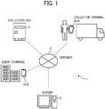
- FIG. 1 illustrates a configuration of a document collection system 1 according to a first embodiment.
- the document collection system 1 is described as an example of collection system of processing target object.
- the processing target object is, for example, confidential document, such as sheet document, paper document or the like. Further, the processing target object is not limited to the confidential document, such as paper document, but can be any processing target object.
- the document collection system 1 (i.e., collection system of processing target object) includes, for example, a collection box 3, an information terminal 4a used by a collector, an information terminal 4b used by a client, and a server 5, connectable one to another via the Internet 2.
- the collection box 3, which is a collection apparatus, is used to collect confidential document (e.g., paper document), which is the processing target object.
- the information terminal 4a used by the collector (hereinafter, collector terminal 4a) is used by a collector handling a collection work of the processing target object.
- the information terminal 4b used by the client (hereinafter, client terminal 4b) is used by the client who requests a collection work of the confidential document to the collector.
- the server 5 functions as a management apparatus of managing a collection work of processing target object.
- the server 5 is implemented by computer. Further, the server 5 may be configured as one physical server or a plurality of physical servers.
- the collector terminal 4a and the client terminal 4b may be a smartphone or a tablet terminal. Further, the collector terminal 4a and the client terminal 4b may be a personal computer or the like.
- FIGs. 2A, 2B, 2C, and 2D illustrate an example of configuration of the collection box 3 used as a collection case or housing, which may be configured, for example, using a box shape.
- the collection box 3 includes, for example, an outer case, such as an outer box 3a, and an inner case, such as an inner box 3b.
- FIG. 2A illustrates an appearance of the collection box 3, which is an appearance of the outer box 3a.
- FIG. 2B illustrates an appearance of a front side of the inner box 3b.
- FIG. 2C illustrates an appearance of ra ear side of the inner box 3b.
- FIG. 2D illustrates an inside of the inner box 3b.
- the collection box 3 is an example of collection apparatus.
- the collection box 3 employs a double structure of the outer box 3a of box shape and the inner box 3b of box shape included inside the outer box 3a, which is known as box-in-box. Further, the shape of the collection box 3, the outer box 3a, and the inner box 3b are not limited to the box shape.
- the collection box 3 is not limited to the double structure of box-in-box, but the collection box 3 can be configured using the inner box 3b alone. Further, the collection box 3 may include a pedestal supporting the inner box 3b of the box shape instead of the outer box 3a of the box shape.
- the collection box 3 is a post-type box having an inlet port 31a for the outer box 3a, and an inlet port 31b for the inner box 3b, respectively.
- the inlet port 31a of the outer box 3a is provided on one side face of the outer box 3a. Therefore, the upper face of the outer box 3 a can be configured as a flat face on which packages or the like can be placed. Further, the inlet port 31a of the outer box 3a may be provided on the upper face of the outer box 3a. Further, the upper face of the outer box 3a may not be configured as the flat face.
- the inlet port 31b of the inner box 3b is provided at a position facing the inlet port 31a of the outer box 3a. With this configuration, the inside of the inner box 3b is communicated to the outside of the outer box 3a.
- the inner box 3b accommodates confidential document (e.g., paper document), which is the processing target object, that is inserted through the inlet port 31b.
- confidential document e.g., paper document
- the inlet port 31a of the outer box 3a and the inlet port 31b of the inner box 3b are formed with a given size so that the confidential document cannot be picked up by inserting a hand through the inlet port 31a and the inlet port 31b.
- the inner box 3b is collected by a collector when the inner box 3b is filled with the stored or accommodated confidential document or when the inner box 3b is almost filled with the stored confidential document, and then the collector replaces the filled inner box 3b with an empty inner box 3b.
- a time when the inner box 3b is filled with the stored or accommodated confidential document or almost filled with the stored or accommodated confidential document is simply referred to as the capacity-saturated-time of the collection box 3.
- the outer box 3a and the inner box 3b are made of material having higher hardness.
- the high-hardness material that forms the outer box 3a and the inner box 3b may be, for example, metal plates and molded parts by resin.
- the inner box 3b is made as opaque so that the inside of the inner box 3b cannot be seen from the outside.
- the inside of the inner box 3b is partitioned by a partition plate 32 so that sheet, such as A4 paper, can be placed with two rows. Further, the partition plate 32 may not be provided. Further, as illustrated in FIG. 2D , the inner bottom face of the inner box 3b has an inclined portion 33 inclined toward the partition plate 32 so that the confidential document sheets overlap one to another using the gravity. Further, the inner bottom face of the inner box 3b may be a horizontal face.
- outer box 3a is provided with an open-close door for removing and replacing the inner box 3b.
- the inner box 3b also includes an open-close door 34 at the rear side for removing the stored or accommodated confidential document.
- the open-close door 34 of the inner box 3b can be opened for opening an entire rear face of the inner box 3b.
- the open-close door 34 of the inner box 3b is opened to remove the confidential document with one action.
- the inner box 3b includes a key lock 35 that controls opening and closing of the open-close door 34 to prevent a theft of confidential document stored or accommodated in the inner box 3b.
- the outer box 3a and the inner box 3b are respectively provided with identification information (ID) 36a and identification information (ID) 36b.
- the identification information (ID) 36a and 36b can be respectively provided to the outer box 3a and the inner box 3b, for example, by printing code symbols on the outer box 3a and the inner box 3b, or attaching radio frequency identification (RFID) on the outer box 3a and the inner box 3b.
- RFID radio frequency identification
- the code symbol is respectively printed on the outer box 3a and the inner box 3b to provide the identification information (ID) 36a and the identification information (ID) 36b.
- the identification information (ID) may be also referred to as the identifier.
- the outer box 3a is provided with a sensor 37, which is a capacity level detection unit, for detecting a capacity level of confidential document accumulated in the inner box 3b (e.g., weight of the inner box 3b).
- the sensor 37 used for detecting the capacity level of confidential document in the inner box 3b may be, for example, a weight sensor, and a height sensor. In the embodiment, the weight sensor is adopted.
- the height sensor a line sensor or a plurality of sensors arranged in a row with a pre-set interval may be adopted.
- the height and/or weight of confidential document is used for detecting the capacity level of confidential document, but is not limited thereto.
- the capacity level of confidential document in the inner box 3b means an amount or quantity of confidential document accumulated in the inner box 3b.
- the outer box 3a includes a communication device 38, which communicates with the server 5 via the Internet 2 to communicate data or information, such as capacity level (example of physical quantity) of confidential document, which is the processing target object stored or accommodated in the collection box 3, obtained or acquired from the sensor 37 to the server 5.
- the communication device 38 may use wireless communication or wired communication. In the embodiment, wireless communication is adopted.
- the communication device 38 is, for example, subscriber identification module (SIM) dedicated to data communication.
- SIM subscriber identification module
- the communication device 38 communicates data, such as capacity level of confidential document, which is the processing target object stored or accommodated in the collection box 3, obtained or acquired from the sensor 37 to the server 5 with a given time interval.
- data such as capacity level of confidential document, which is the processing target object stored or accommodated in the collection box 3, obtained or acquired from the sensor 37 to the server 5 with a given time interval.
- the communication device 38 communicates data obtained from the sensor 37 to the server 5 with the given time interval, but is not limited thereto.
- the communication device 38 may communicate at a fixed time point during the daytime, and may not communicate at night, such as midnight, when the measuring by the sensor 37 is not required.
- the communication device 38 may be set with a communication time interval, such as 2 hours, 3 hours, 2 hours, and 3 hours, without setting the given same time interval.
- the outer box 3a includes a power supply 39 for supplying power to the sensor 37 and the communication device 38.
- the power supply 39 may include an outlet power source, a battery or a solar cell.
- the inner box 3b includes a tire 40 to facilitate a carrying operation of the inner box 3b. Further, the inner box 3b may not have the tire 40.
- the inner box 3b includes a handle 41 to facilitate a carrying operation and a lifting operation of the inner box 3b. Further, the inner box 3b may not have the handle 41.
- FIG. 3 is an example of configuration of hardware block diagram of the server 5.
- the server 5 constructed by a computer, includes, for example, central processing unit (CPU) 501, read only memory (ROM) 502, random access memory (RAM) 503, hard disk (HD) 504, hard disk drive (HDD) controller 505, display 506, external device connection interface (I/F) 508, network interface (I/F) 509, data bus 510, keyboard 511, pointing device 512, digital versatile disk rewritable (DVD-RW) drive 514, and media interface (I/F) 516.
- CPU central processing unit
- ROM read only memory
- RAM random access memory
- HD hard disk
- HDD hard disk drive
- display 506 external device connection interface
- I/F external device connection interface
- I/F network interface
- data bus 510 keyboard 511
- pointing device 512 digital versatile disk rewritable (DVD-RW) drive 514
- media interface (I/F) 516 media interface
- the CPU 501 controls the operation of the server 5 entirely.
- the ROM 502 stores programs used for driving the CPU 501, such as initial program loader (IPL).
- the RAM 503 is used as a work area of the CPU 501.
- the HD 504 stores various data, such as programs.
- the HDD controller 505 controls reading and writing of various data with the HD 504 under the control of the CPU 501.
- the display 506 displays various information such as cursor, menus, windows, characters, or images.
- the external device connection I/F 508 is an interface for connecting various external devices.
- the external device is, for example, a universal serial bus (USB) memory, a printer, or the like.
- the network I/F 509 is an interface for performing data communication by utilizing a communication network 100.
- the data bus 510 is address bus and data bus used for electrically connecting each of the components, such as the CPU 501, illustrated in FIG. 3 .
- the keyboard 511 is a type of input unit having a plurality of keys used for inputting characters, numerals, various instructions, or the like.
- the pointing device 512 is a type of input unit used for selecting and executing various instructions, selecting a process target, moving a cursor, or the like.
- the DVD-RW drive 514 controls reading and writing of various data with the DVD-RW 513 used as an example of removable recording media. Further, the computer may use digital versatile disk recordable (DVD-R) in addition to or instead of DVD-RW.
- DVD-R digital versatile disk recordable
- the media I/F 516 controls reading and writing (storing) of data with a recording medium 515, such as flash memory.
- the programs executable by the server 5 according to the above-described embodiment may be recorded on a computer-readable recoding medium, such as compact disk read only memory (CD-ROM), flexible disk (FD), compact disk-recordable (CD-R), and digital versatile disc (DVD) as files in an installable format or executable format.
- a computer-readable recoding medium such as compact disk read only memory (CD-ROM), flexible disk (FD), compact disk-recordable (CD-R), and digital versatile disc (DVD) as files in an installable format or executable format.
- the programs executable by the server 5 according to the embodiment may be stored in one or more computers connected to a network, such as the Internet, and downloaded via the network. Further, the programs executable by the server 5 according to the embodiment may be provided or distributed over a network, such as the Internet.
- the collector terminal 4a and the client terminal 4b are described as a smartphone 4 (see FIG. 4 ).
- FIG. 4 is an example of configuration of hardware block diagram of the smartphone 4.
- the smartphone 4 includes, for example, CPU 401, ROM 402, RAM 403, electrically erasable programmable read-only memory (EEPROM) 404, complementary metal oxide semiconductor (CMOS) sensor 405, imaging element interface (I/F) 406, acceleration-orientation sensor 407, media I/F 409, and global positioning system (GPS) receiver 411.
- CPU 401 central processing unit (CPU) programmable read-only memory
- CMOS complementary metal oxide semiconductor
- I/F imaging element interface
- I/F acceleration-orientation sensor
- media I/F 409 media I/F 409
- GPS global positioning system
- the CPU 401 controls the operation of the smartphone 4 entirely.
- the ROM 402 stores programs used for driving the CPU 401, such as initial program loader (IPL).
- the RAM 403 is used as a work area of the CPU 401 of the smartphone 4.
- the EEPROM 404 reads or writes various data, such as a program for smartphone under the control of the CPU 401.
- the CMOS sensor 405 is a type of built-in imaging unit that captures images of objects, such as image of user, and acquires the image data under the control of the CPU 401. Further, the charge coupled device (CCD) sensor may be used an imaging unit for the smartphone 4 instead of the CMOS sensor.
- the imaging element I/F 406 is a circuit that controls the driving of the CMOS sensor 405.
- the acceleration-orientation sensor 407 includes various sensors, such as an electronic magnetic compass to detect the geomagnetism, a gyrocompass, and an acceleration sensor.
- the media I/F 409 controls reading and writing (storing) of data to a recording medium 408, such as flash memory.
- the GPS receiver 411 receives GPS signals from GPS satellites.
- the smartphone 4 further includes, for example, long-range communication circuit 412, CMOS sensor 413, imaging element I/F 414, microphone 415, speaker 416, audio input-output interface (I/F) 417, display 418, external device connection I/F 419, short-range communication circuit 420, antenna 420a of the short-range communication circuit 420, and touch panel 421.
- the long-range communication circuit 412 is a circuit that communicates with other device via the communication network 100.
- the CMOS sensor 413 is a type of built-in imaging unit for capturing images of objects and acquiring image data of objects under the control of CPU 401.
- the imaging element I/F 414 is a circuit that controls the driving of the CMOS sensor 413.
- the microphone 415 is a type of built-in circuit that converts audio signals into electrical signals.
- the speaker 416 is a type of built-in circuit that converts electrical signals into physical vibration to generate audio, such as music and voice.
- the audio input-output I/F 417 is a circuit that processes input and output of the audio signals with the microphone 415 and the speaker 416 under the control of the CPU 401.
- the display 418 is a type of display unit, such as liquid crystal and organic electro luminescence (OEL), which displays images of objects and various icons, or the like.
- OEL organic electro luminescence
- the external device connection I/F 419 is an interface for connecting various external devices.
- the short-range communication circuit 420 is a communication circuit, such as near field communication (NFC) and Bluetooth (registered trademark).
- the touch panel 421 is a type of input unit for operating the smartphone 4 by the user by pressing the display 418.
- the smartphone 4 further includes, for example, bus line 410.
- the bus line 410 is address bus and data bus for electrically connecting each of the components, such as the CPU 401 illustrated in FIG. 4 .
- the smartphone program executable by the smartphone 4 according to the above-described embodiment may be recorded on a computer-readable recoding medium, such as compact disk read only memory (CD-ROM), flexible disk (FD), compact disk-recordable (CD-R), and digital versatile disc (DVD) as files in an installable format or executable format.
- a computer-readable recoding medium such as compact disk read only memory (CD-ROM), flexible disk (FD), compact disk-recordable (CD-R), and digital versatile disc (DVD) as files in an installable format or executable format.
- the smartphone program executable by the smartphone 4 according to the embodiment may be stored in one or more computers connected to a network, such as the Internet, and downloaded via the network. Further, the smartphone program executable by the smartphone 4 according to the embodiment may be provided or distributed over a network, such as the Internet.
- the smartphone program executable by the smartphone 4 according to the embodiment can be provided in advance in ROM or the like disposed in the smartphone 4.
- the document collection processing may be also referred to as the collection work of document, such as confidential document.
- FIG. 5 is an example of configuration of functional block diagram used for document collection processing performed by the CPU 501 of the server 5.
- the server 5 includes, for example, capacity level receiving unit 51, collection determination unit 52, first transmission unit 53, second transmission unit 54, and data storage unit 55.
- the capacity level receiving unit 51 receives a capacity level of the confidential document, which is the processing target object, stored or accommodated in the collection box 3.
- the capacity level of the confidential document indicates physical quantity of the confidential document stored or accommodated in the collection box 3.
- the collection determination unit 52 determines whether the confidential document, which is the processing target object, is to be collected based on weight data or information (i.e., physical quantity) on the confidential document received by the capacity level receiving unit 51 from the collection box 3. More specifically, the collection determination unit 52 creates and determines a collection plan, such as a collection schedule of the confidential document based on the capacity level of the confidential document notified from the collection box 3 provided at a plurality of locations.
- the location indicates a place where the collection box 3 is located. Therefore, if the collection box 3 is disposed at each building of separate addresses, each building at each address becomes the location. Further, if the collection box 3 is disposed at each floor of the same building, each floor of the same building becomes the location. Further, if the collection box 3 is disposed at each separate place in the same floor, each separate place in the same floor becomes the location.
- the collection schedule means collection date/time and collection route.
- the collection date/time may be time alone, date alone, and time zone of AM/PM.
- the collection route is not limited to a route of buildings at different addresses described above, but the collection route may be a route of floors in the same building, and a route of places on the same floor.
- the collection schedule may be any one of the collection date/time and the collection route. If the building set as the collection destination is determined in advance, the collection schedule may be time alone or time zone alone. Further, if the collection date is a fixed date, the collection schedule may be the collection route alone if only one collection day is considered.
- the collection determination unit 52 predicts the capacity-saturated-time for each collection box 3 based on the current capacity level of box (e.g., amount of accumulated document or remaining available capacity level), past capacity level, transition of past capacity level, date and time information, and operation day information.
- the current capacity level of box e.g., amount of accumulated document or remaining available capacity level
- past capacity level e.g., amount of accumulated document or remaining available capacity level
- transition of past capacity level e.g., date and time information
- operation day information e.g., time of past capacity level
- the collection determination unit 52 calculates an optimum collection route for a plurality of collection boxes 3 whose capacity level of the confidential document exceeds a given threshold value. For example, the collection determination unit 52 calculates the optimum collection route of a collection vehicle (e.g., truck) based on the current capacity level of box (e.g., amount of accumulated document or remaining available capacity level), position information, map information, and collector information.
- a collection vehicle e.g., truck
- the first transmission unit 53 transmits the date and time of the collection schedule of the confidential document, determined by the collection determination unit 52, to the client terminal 4b. For example, the first transmission unit 53 notifies the collection day and collection time to the client terminal 4b by email and/or web system.
- the second transmission unit 54 transmits the collection destination and the collection schedule (date and time, collection route) of the confidential document, determined by the collection determination unit 52, to the collector terminal 4a of the collector handling the collection work of confidential document.
- the second transmission unit 54 transmits the collection plan for each collection vehicle (e.g., truck) operated by the collector, such as collection contractor.
- the data storage unit 55 stores at least the capacity level and date information of the confidential document in association with the identification information (ID) 36a of the outer box 3a and the identification information (ID) 36b of the inner box 3b of the collection box 3.
- FIGs. 6A and 6B illustrate examples of data table storing various data related to the collection work of confidential document.
- the data storage unit 55 configures a data table for storing various data related to the collection work of confidential document in the HD 504.
- the data table illustrated in FIG. 6A is an example of collection data table T1, which stores various information, such as communication date and time, identification information (ID) 36a of the outer box 3a, identification information (ID) 36b of the inner box 3b, client information (e.g., name), address, and capacity level in association with each other.
- the data table illustrated in FIG. 6B is an example of discard data table T2, which stores various information, such as identification information (ID) 36b of the inner box 3b, identification information (ID) 36a of the outer box 3a, client information (e.g., name), address, discarded date, capacity level, and status in association with each other for each of the identification information (ID) 36b of the inner box 3b.
- ID identification information
- ID identification information
- ID identification information
- the collection determination unit 52 determines the collection work of confidential document by referring to the collection data table T1 illustrated in FIG. 6A . Further, the collection determination unit 52 updates the collection data table T1 illustrated in FIG. 6A after performing the collection work of confidential document.
- the collection determination unit 52 updates the discard data table T2 illustrated in FIG. 6B after performing the collection work and the discarding work of confidential document.
- FIG. 7 is a flowchart illustrating a process of monitoring capacity level at the server 5.
- the data storage unit 55 of the server 5 stores the capacity level of each collection box 3, which is reported or notified from each collection box 3 with a given time interval, in the collection data table T1 (step S1).
- the data storage unit 55 determines that an error occurs on communication with the collection box 3.
- the data storage unit 55 of the server 5 notifies an organization that manages the system operation in a case of communication error.
- the error detection may or may not be performed depending on situations.
- the collection determination unit 52 of the server 5 predicts the capacity-saturated-time of each collection box 3 based on the current capacity level, past capacity level, transition of past capacity level, date and time information, and operation day information stored in the collection data table T1 illustrated in FIG. 6A (step S2).
- the prediction of capacity-saturated-time of the collection box 3 can be performed, for example, using the regression analysis setting the operation time period as a parameter X and the capacity level as a parameter Y.
- the collection determination unit 52 of the server 5 selects one or more of the collection boxes 3 whose capacity level exceed a given threshold level, as the collection destination (step S3).
- FIG. 8 is a flowchart illustrating a flow of processing of selecting a collection route at the server 5.
- the collection determination unit 52 of the server 5 calculates the optimum collection route that can set the shortest collection time required for collecting the collection box 3 whose capacity level exceeding the given threshold level for each collection vehicle, such as truck (step S11).
- the optimum collection route may be the shortest collection distance or the lowest collection fee amount.
- the collection determination unit 52 of the server 5 may add the one collection box 3 to the collection destination. Further, even if the capacity level of one collection box 3 has exceeded the given threshold level, if the required collection time of the one collection box 3 is expected to be longer and the one collection box 3 can be waited for the collection work for a few days later, the collection determination unit 52 of the server 5 excludes the one collection box 3 from the collection destination. That is, based on the detected capacity level of each collection box 3, the collection determination unit 52 of the server 5 determines which confidential document stored or accommodated in which collection box 3 is to be collected or recovered among the collection boxes 3 storing or accommodating the confidential document.
- the first transmission unit 53 of the server 5 transmits the scheduled collection date/time to the client terminal 4b before the scheduled collection date (step S12).
- the client inputs an acceptance or a change request to the scheduled collection date/time using the client terminal 4b, and answers to the server 5 (step S13)
- step S13 If the server 5 receives a request for changing the scheduled collection date/time from the client terminal 4b (step S13: YES), the server 5 re-calculates the collection route (step S14).
- the second transmission unit 54 of the server 5 transmits the collection destination, collection date/time, and collection route to the collector terminal 4a (step S15).
- the collector visits the collection destination based on the collection destination, collection date/time, and collection route, instructed by the server 5. Then, the collector changes or replaces the existing inner box 3b of the collection box 3 at the collection destination with another inner box 3b that is empty.
- the collector uses the collector terminal 4a to read the identification information (ID) 36a of the outer box 3a, the identification information (ID) 36b of the inner box 3b (i.e., collection target) of the collection box 3 disposed at the collection destination, and the identification information (ID) 36b of the inner box 3b of empty (i.e., new inner box 3b), and then the collector notifies a replacement of inner box 3b to the server 5, with which the system configured using the server 5 recognizes that the inner box 3b is replaced. Further, the collector also transmits a collection completion signature signed by the client to the server 5 from the collector terminal 4a.
- the collector carries the collected inner box 3b into a cargo of a truck having a lock, and locks the cargo of the truck.
- the collector drives the truck to deliver the inner box 3b to a discarding plant or facility.
- the discarding plant shall have a lockable-closed processing space, and shall allow an entry of specific limited persons.
- the key at discarding plant may be a fingerprint authentication or a general key.
- the collector unloads the inner box 3b at the discarding plant or facility from the truck, reads the identification information (ID) 36b of the inner box 3b using the collector terminal 4a, and then notifies the unloading of the inner box 3b to the server 5, with which the server 5 recognizes that the confidential document is unloaded from the truck.
- ID identification information
- another information terminal may be provided at the discarding plant or facility.
- the another information terminal can be used to read the identification information (ID) 36b of the inner box 3b and to notify the unloading of the inner box 3b to the server 5.
- ID identification information
- the collector opens the open-close door 34 of the inner box 3b at the discarding plant or facility, and then destroys the confidential document by injecting or inserting the confidential document into a confidential document processing machine.
- the collector reads the identification information (ID) 36b of the inner box 3b using the collector terminal 4a at the discarding plant or facility, and then notifies the destroying of confidential document to the server 5, with which the server 5 recognizes that the confidential document is destroyed and deleted.
- ID identification information
- another information terminal may be provided at the discarding plant or facility.
- the another information terminal can be used to read the identification information (ID) 36b of the inner box 3b and to notify the destroying of confidential document to the server 5.
- ID identification information
- FIG. 9 is a flowchart illustrating a processing of managing status at the server 5.
- FIG. 10 is an example of the collection data table T1 after performing the collection work.
- FIGs. 11A, 11B, and 11C are examples of the discard data table T2 after performing the collection work or after performing the discarding work.
- the collection determination unit 52 of the server 5 resets a relationship between the outer box 3a and the inner box 3b for each collection box 3 (step S21). For example, as to the collection data table T1 illustrated in FIG. 10 , the identification information (ID) 36b of the inner box 3b is changed, and the capacity level is also changed to "0 kg.”
- the collection determination unit 52 of the server 5 stores the identification information (ID) 36b of the inner box 3b replaced by the collector (step S22).
- the collection determination unit 52 of the server 5 sets the status of the inner box 3b collected by the collector as "collected” and adds the status of "collected” based on the collection completion signature signed by the client, received from the collector terminal 4a (step S23).
- the discard data table T2 stores data associated with the identification information (ID) 36b of the collected inner box 3b having the status of "collected.”
- the collection determination unit 52 of the server 5 adds the status of the collected inner box 3b as "delivered" at the discarding plant or facility (step S24).
- the discard data table T2 stores data associated with the identification information (ID) 36b of the collected inner box 3b having the status of "delivered.”
- the collection determination unit 52 of the server 5 adds the status of the collected inner box 3b as "deleted" (step S25).
- the discard data table T2 stores data associated with the identification information (ID) 36b of the collected inner box 3b having the status of "deleted.”
- the collection determination unit 52 of the server 5 issues a deletion certificate and collection history of the confidential information, and notifies the deletion certificate and the collection history of the confidential information to the client terminal 4b (step S26).
- the collection determination unit 52 of the server 5 calculates the cost of collection work, and charges the client the cost of collection work based on the weight of the inner box 3b and the subscribed contract (step S27).
- the cost of collection work may be calculated based on the re-measurement at the discarding plant or facility.
- the client can download and print the collection history and the deletion certificate from the server 5 using the client terminal 4b.
- the processing target object can be collected efficiently and simple manner.
- the collection box 3 employs the double structure, with which the security can be set higher, and the confidential document can be collected without shredding the confidential document, and thereby sheets, such as paper, can be used for recycling, such as material recycling.
- the collection box 3 can transmit information on the capacity level to the server 5 at a given timing, and then the server 5 can predict the capacity-saturated-time of the collection box 3 and the optimum collection schedule (date and time, route), and thereby the collection efficiency can be improved compared to conventional collection systems.
- the management apparatus includes the capacity level receiving unit 51 configured to receive information on physical quantity of the particular processing target object accumulated in each of a plurality of collection boxes 3 provided respectively at a plurality of locations, and the collection determination unit 52 configured to determine a collection plan of the particular processing target object accumulated in each of the plurality of collection boxes 3 based on the information on the physical quantity of the particular processing target object accumulated in each of the plurality of collection boxes 3 detected by the sensor 37 used as the capacity level detection unit.
- the collection determination unit 52 determines a collection schedule of the particular processing target object based on the information on the physical quantity of the particular processing target object notified from the each of the plurality of collection boxes 3 provided respectively at the plurality of locations.
- the collection determination unit 52 calculates an optimum collection route for each of the plurality of the collection boxes 3 whose physical quantity of the particular processing target object exceeds a given threshold value.
- the management apparatus further includes the first transmission unit 53 configured to transmit the collection schedule of the particular processing target object, determined by the collection determination unit 52, to a plurality of information terminals disposed at the plurality of locations.
- the management apparatus further includes the second transmission unit 54 configured to transmit the collection schedule of the particular processing target object, determined by the collection determination unit 52, to the information terminal 4a (i.e., collector terminal 4a) used by a collector handling a collection work of the particular processing target object.
- the information terminal 4a i.e., collector terminal 4a
- the management apparatus further includes the data storage unit 55 configured to store at least the information on the physical quantity of the particular processing target object and date and time information in association with identification information of the collection box 3, and the collection determination unit 52 determines the collection of the particular processing target object by referring to the data storage unit 55.
- the collection determination unit 52 predicts a capacity-saturated-time of the collection box 3 based on current physical quantity, past physical quantity physical quantities, transition of past physical quantity, and operation day information.
- the collection determination unit 52 updates information stored in the data storage unit 55 after collecting the particular processing target object.
- processing target object can be collected efficiently using simple processing.
- Processing circuitry includes a programmed processor, as a processor includes circuitry.
- a processing circuit also includes devices such as an application specific integrated circuit (ASIC), digital signal processor (DSP), field programmable gate array (FPGA), and conventional circuit components arranged to perform the recited functions.
- ASIC application specific integrated circuit
- DSP digital signal processor
- FPGA field programmable gate array
- the server 5 may include a plurality of computing devices as a server cluster.
- the plurality of computing devices are configured to communicate with each other via any type of communication link, including a network or shared memory, and perform the processing disclosed in this description.
- the inner box 3b includes a guide member, such as a guide plate (e.g., slide plate) that guides documents, such as confidential documents (e.g., sheet documents) inserted through the inlet port 31b to securely store or accommodate the confidential documents (e.g., sheet documents), which is different from the first embodiment.
- a guide member such as a guide plate (e.g., slide plate) that guides documents, such as confidential documents (e.g., sheet documents) inserted through the inlet port 31b to securely store or accommodate the confidential documents (e.g., sheet documents), which is different from the first embodiment.
- FIG. 12 illustrates an example of configuration of the collection box 3 according to the second embodiment.
- FIG. 12A illustrates a front appearance of the collection box 3, which is a front appearance of the outer box 3a.
- FIG. 12B illustrates a cross sectional view of the collection box 3.
- the outer box 3a of the collection box 3 of the second embodiment includes two inlet ports 31a-1 and 31a-2 arranged on the right side and the left side, as the inlet port 31a collectively.
- the two inlet ports 31a-1 and 31a-2 are respectively arranged on the right side and the left side relative to the partition plate 32 provided at the center of inside the inner box 3b.
- each of the two inlet ports 31a-1 and 31a-2 has a given width that allows the insertion of given sheets, such as A4 sheet along the longitudinal direction of A4 sheet.
- the confidential documents (e.g., sheet documents) of A4 sheet When the confidential documents (e.g., sheet documents) of A4 sheet are inserted into each of the two inlet ports 31a-1 and 31a-2 arranged at the right side and the left side, the confidential documents (e.g., sheet documents) of A4 sheet can be separated into two rows, corresponding to the two inlet ports 31a-1 and 31a-2 where the confidential documents (e.g., sheet documents) of A4 sheet are inserted into, by the partition plate 32 of the inner box 3b.
- the confidential documents (e.g., sheet documents) of A4 sheet When the confidential documents (e.g., sheet documents) of A4 sheet are inserted into each of the two inlet ports 31a-1 and 31a-2 arranged at the right side and the left side, the confidential documents (e.g., sheet documents) of A4 sheet can be separated into two rows, corresponding to the two inlet ports 31a-1 and 31a-2 where the confidential documents (e.g., sheet documents) of A4 sheet are
- the outer box 3a of the collection box 3 of the second embodiment is provided with a guide plate 50 (e.g., slide plate) for each of the two inlet ports 31a-1 and 31a-2.
- the guide plate 50 passes and extends through the inlet port 31b of the inner box 3b.
- the guide plate 50 functions as the guide member.
- the guide plate 50 e.g., slide plate
- a length (depth length) of the guide plate 50 is set to a given length so that the inserted confidential documents (e.g., sheet documents) do not drop directly onto the inner bottom face of the inner box 3b when the inserted confidential documents (e.g., sheet documents) fall inside the inner box 3b.
- the length (depth length) of the guide plate 50 is preferably set to a given particular length to direct the inserted confidential documents (e.g., sheet documents) to hit a corner of the inner bottom face of the inner box 3b when the inserted confidential documents (e.g., sheet documents) fall inside the inner box 3b.
- the inserted confidential documents e.g., sheet documents
- the inserted confidential documents do not drop directly onto the inner bottom face of the inner box 3b, with which a situation that the inserted confidential documents (e.g., sheet documents) are randomly stacked inside the inner box 3b can be prevented.
- the length (depth length) of the guide plate 50 is set depending on a size of the collection box 3 (inner box 3b). Therefore, a size of the guide plate 50 is set to a give size capable of adjusting the length (depth length) of the guide plate 50 with respect to an internal space of the collection box 3 (inner box 3b) used for accommodating sheets having a given sheet size, such as A4.
- the guide plate 50 can be provided with a variable adjustment mechanism, which can variably adjust the length (depth length) and an angle of the guide plate 50 based on the total amount (e.g., weight) of confidential documents (e.g., sheet documents) inserted in the inner box 3b, to change a drop position of the confidential documents (e.g., sheet documents) inserted in the inner box 3b.
- a variable adjustment mechanism which can variably adjust the length (depth length) and an angle of the guide plate 50 based on the total amount (e.g., weight) of confidential documents (e.g., sheet documents) inserted in the inner box 3b, to change a drop position of the confidential documents (e.g., sheet documents) inserted in the inner box 3b.
- the inner bottom face of the inner box 3b may be configured to be a face movable upward and downward directions to change the drop position of the confidential documents (e.g., sheet documents) inserted in the inner box 3b.
- the confidential documents e.g., sheet documents
- the guide plate 50 (e.g., slide plate) is provided to each of the two inlet ports 31a-1 and 31a-2, but is not limited thereto.
- the guide plate 50 e.g., slide plate
- the guide plate 50 can be provided for the inlet port 31a described in the first embodiment of this disclosure.
- the guide plate 50 (e.g., slide plate) is provided for each of the two inlet ports 31a-1 and 31a-2, but is not limited thereto.
- the guide plate 50 e.g., slide plate
- the guide plate 50 can be provided to the inlet port 31b of the inner box 3b.
- the present invention can be implemented in any convenient form, for example using dedicated hardware, or a mixture of dedicated hardware and software.
- the present invention may be implemented as computer software implemented by one or more networked processing apparatuses.
- the network can comprise any conventional terrestrial or wireless communications network, such as the Internet.
- the processing apparatuses can compromise any suitably programmed apparatuses such as a general purpose computer, personal digital assistant, mobile telephone (such as a WAP or 3G-compliant phone) and so on. Since the present invention can be implemented as software, each and every aspect of the present invention thus encompasses computer software implementable on a programmable device.
- the computer software can be provided to the programmable device using any conventional carrier medium.
- the carrier medium can compromise a transient carrier medium such as an electrical, optical, microwave, acoustic or radio frequency signal carrying the computer code.
- a transient carrier medium such as an electrical, optical, microwave, acoustic or radio frequency signal carrying the computer code.
- An example of such a transient medium is a TCP/IP signal carrying computer code over an IP network, such as the Internet.
- the carrier medium can also comprise a storage medium for storing processor readable code such as a floppy disk, hard disk, CD ROM, magnetic tape device or solid state memory device.
- the hardware platform includes any desired kind of hardware resources including, for example, a central processing unit (CPU), a random access memory (RAM), and a hard disk drive (HDD).
- the CPU may be implemented by any desired kind of any desired number of processor.
- the RAM may be implemented by any desired kind of volatile or non-volatile memory.
- the HDD may be implemented by any desired kind of non-volatile memory capable of storing a large amount of data.
- the hardware resources may additionally include an input device, an output device, or a network device, depending on the type of the apparatus. Alternatively, the HDD may be provided outside the apparatus as long as the HDD is accessible.
- the CPU such as a cashe memory of the CPU
- the RAM may function as a physical memory or a primary memory of the apparatus, while the HDD may function as a secondary memory of the apparatus.
Landscapes
- Business, Economics & Management (AREA)
- Tourism & Hospitality (AREA)
- Engineering & Computer Science (AREA)
- Marketing (AREA)
- Health & Medical Sciences (AREA)
- Economics (AREA)
- General Health & Medical Sciences (AREA)
- Human Resources & Organizations (AREA)
- Technology Law (AREA)
- Primary Health Care (AREA)
- Strategic Management (AREA)
- Physics & Mathematics (AREA)
- General Business, Economics & Management (AREA)
- General Physics & Mathematics (AREA)
- Theoretical Computer Science (AREA)
- Management, Administration, Business Operations System, And Electronic Commerce (AREA)
Abstract
A system (1) for collecting processing target object includes a plurality of collection apparatuses (3), provided respectively at a plurality of locations, each configured to accumulate the processing target object in each of the plurality of collection apparatuses (3); a capacity level detection unit (37), provided for each of the plurality of collection apparatuses (3), configured to detect physical quantity of the processing target object accumulated in each of the plurality of collection apparatuses (3); and a collection determination unit (52) configured to determine a collection plan of the processing target object accumulated in each of the plurality of collection apparatuses (3) based on information on the physical quantity of the processing target object accumulated in each of the plurality of collection apparatuses (3) detected by the capacity level detection unit (37).
Description
- This disclosure relates to a system for collecting processing target object, a management apparatus for managing a collection work of processing target object, and a method for managing a collection work of processing target object.
-
JP-2012-131597-A - Further,
JP-2007-042076-A JP-2007-042076-A - Further, as to the technology disclosed in
JP-2012-131597-A JP-2012-131597-A - Further, as to the technology disclosed in
JP-2007-042076-A - As one aspect of the present disclosure, a system for collecting processing target object is devised. The system includes a plurality of collection apparatuses, provided respectively at a plurality of locations, each configured to accumulate the processing target object in each of the plurality of collection apparatuses; a capacity level detection unit, provided for each of the plurality of collection apparatuses, configured to detect physical quantity of the processing target object accumulated in each of the plurality of collection apparatuses; and a collection determination unit configured to determine a collection plan of the processing target object accumulated in each of the plurality of collection apparatuses based on information on the physical quantity of the processing target object accumulated in each of the plurality of collection apparatuses detected by the capacity level detection unit.
- As another aspect of the present disclosure, a management apparatus for managing a collection work of processing target object is devised. The management apparatus includes a capacity level receiving unit configured to receive information on physical quantity of the processing target object accumulated in each of a plurality of collection apparatuses provided respectively at a plurality of locations; and a collection determination unit configured to determine a collection plan of the processing target object accumulated in each of the plurality of collection apparatuses based on the information on the physical quantity of the processing target object accumulated in each of the plurality of collection apparatuses detected by the capacity level detection unit.
- As another aspect of the present disclosure, a method for managing a collection work of processing information is devised. The method includes detecting physical quantity of the processing target object accumulated in each of a plurality of collection apparatuses provided respectively at a plurality of locations; and determining a collection plan of the processing target object accumulated in each of the plurality of collection apparatuses based on information on the detected physical quantity of the processing target object accumulated in each of the plurality of collection apparatuses.
- As to the above described aspects of the present disclosure, processing target object can be collected efficiently using simple processing.
- A more complete appreciation of the description and many of the attendant advantages and features thereof can be readily acquired and understood from the following detailed description with reference to the accompanying drawings, wherein:
-
FIG. 1 illustrates a configuration of a document collection system according to a first embodiment of this disclosure; -
FIGs. 2A, 2B, 2C, and 2D illustrate an example of configuration of a collection box; -
FIG. 3 is an example of configuration of hardware block diagram of a server; -
FIG. 4 is an example of configuration of hardware block diagram of a smartphone; -
FIG. 5 is an example of configuration of functional block diagram used for document collection processing performed by CPU of a server; -
FIGs. 6A and 6B illustrate examples of data table storing various data related to collection work of confidential document; -
FIG. 7 is a flowchart illustrating a processing of monitoring capacity level using a server; -
FIG. 8 is a flowchart illustrating a flow of processing of selecting collection route using a server; -
FIG. 9 is a flowchart illustrating a flow of processing of managing status using a server; -
FIG. 10 is an example of collection data table after performing a collection work; and -
FIGs. 11A, 11B, and 11C are examples of discard data table after performing a collection work or after performing a discarding work; and -
FIGs. 12A and 12B illustrate an example of configuration of a collection box according to a second embodiment of this disclosure. - The accompanying drawings are intended to depict embodiments of the this disclosure and should not be interpreted to limit the scope thereof. The accompanying drawings are not to be considered as drawn to scale unless explicitly noted.
- A description is now given of exemplary embodiments of the present inventions. It should be noted that although such terms as first, second, etc. may be used herein to describe various elements, components, regions, layers and/or units, it should be understood that such elements, components, regions, layers and/or units are not limited thereby because such terms are relative, that is, used only to distinguish one element, component, region, layer or unit from another region, layer or unit. Thus, for example, a first element, component, region, layer or unit discussed below could be termed a second element, component, region, layer or unit without departing from the teachings of the present inventions.
- Further, it should be noted that the terminology used herein is for the purpose of describing particular embodiments only and is not intended to be limiting of the present inventions. Thus, for example, as used herein, the singular forms "a", "an" and "the" are intended to include the plural forms as well, unless the context clearly indicates otherwise. Moreover, the terms "includes" and/or "including," when used in this specification, specify the presence of stated features, integers, steps, operations, elements, and/or components, but do not preclude the presence or addition of one or more other features, integers, steps, operations, elements, components, and/or groups thereof.
- Hereinafter, a description is given of an embodiment of a collection system of processing target object, a management apparatus of managing a collection work of processing target object, and a method of managing a collection work of processing target object with reference to the accompanying drawings.
-
FIG. 1 illustrates a configuration of adocument collection system 1 according to a first embodiment. Thedocument collection system 1 is described as an example of collection system of processing target object. In this description, the processing target object is, for example, confidential document, such as sheet document, paper document or the like. Further, the processing target object is not limited to the confidential document, such as paper document, but can be any processing target object. - As illustrated in
FIG. 1 , the document collection system 1 (i.e., collection system of processing target object) includes, for example, acollection box 3, aninformation terminal 4a used by a collector, aninformation terminal 4b used by a client, and aserver 5, connectable one to another via the Internet 2. Thecollection box 3, which is a collection apparatus, is used to collect confidential document (e.g., paper document), which is the processing target object. Theinformation terminal 4a used by the collector (hereinafter,collector terminal 4a) is used by a collector handling a collection work of the processing target object. Theinformation terminal 4b used by the client (hereinafter,client terminal 4b) is used by the client who requests a collection work of the confidential document to the collector. - The
server 5 functions as a management apparatus of managing a collection work of processing target object. Theserver 5 is implemented by computer. Further, theserver 5 may be configured as one physical server or a plurality of physical servers. - The
collector terminal 4a and theclient terminal 4b may be a smartphone or a tablet terminal. Further, thecollector terminal 4a and theclient terminal 4b may be a personal computer or the like. - Hereinafter, with reference to
FIG. 2 , a description is given of thecollection box 3.FIGs. 2A, 2B, 2C, and 2D illustrate an example of configuration of thecollection box 3 used as a collection case or housing, which may be configured, for example, using a box shape. Thecollection box 3 includes, for example, an outer case, such as anouter box 3a, and an inner case, such as aninner box 3b.FIG. 2A illustrates an appearance of thecollection box 3, which is an appearance of theouter box 3a.FIG. 2B illustrates an appearance of a front side of theinner box 3b.FIG. 2C illustrates an appearance of ra ear side of theinner box 3b.FIG. 2D illustrates an inside of theinner box 3b. Thecollection box 3 is an example of collection apparatus. - As illustrated in
FIGs. 2A and 2B , thecollection box 3 employs a double structure of theouter box 3a of box shape and theinner box 3b of box shape included inside theouter box 3a, which is known as box-in-box. Further, the shape of thecollection box 3, theouter box 3a, and theinner box 3b are not limited to the box shape. - Further, the
collection box 3 is not limited to the double structure of box-in-box, but thecollection box 3 can be configured using theinner box 3b alone. Further, thecollection box 3 may include a pedestal supporting theinner box 3b of the box shape instead of theouter box 3a of the box shape. - The
collection box 3 is a post-type box having aninlet port 31a for theouter box 3a, and aninlet port 31b for theinner box 3b, respectively. Theinlet port 31a of theouter box 3a is provided on one side face of theouter box 3a. Therefore, the upper face of theouter box 3 a can be configured as a flat face on which packages or the like can be placed. Further, theinlet port 31a of theouter box 3a may be provided on the upper face of theouter box 3a. Further, the upper face of theouter box 3a may not be configured as the flat face. - The
inlet port 31b of theinner box 3b is provided at a position facing theinlet port 31a of theouter box 3a. With this configuration, the inside of theinner box 3b is communicated to the outside of theouter box 3a. Theinner box 3b accommodates confidential document (e.g., paper document), which is the processing target object, that is inserted through theinlet port 31b. Further, theinlet port 31a of theouter box 3a and theinlet port 31b of theinner box 3b are formed with a given size so that the confidential document cannot be picked up by inserting a hand through theinlet port 31a and theinlet port 31b. - The
inner box 3b is collected by a collector when theinner box 3b is filled with the stored or accommodated confidential document or when theinner box 3b is almost filled with the stored confidential document, and then the collector replaces the filledinner box 3b with an emptyinner box 3b. Hereinafter, a time when theinner box 3b is filled with the stored or accommodated confidential document or almost filled with the stored or accommodated confidential document is simply referred to as the capacity-saturated-time of thecollection box 3. - The
outer box 3a and theinner box 3b are made of material having higher hardness. The high-hardness material that forms theouter box 3a and theinner box 3b may be, for example, metal plates and molded parts by resin. Further, theinner box 3b is made as opaque so that the inside of theinner box 3b cannot be seen from the outside. - As illustrated in
FIG. 2D , the inside of theinner box 3b is partitioned by apartition plate 32 so that sheet, such as A4 paper, can be placed with two rows. Further, thepartition plate 32 may not be provided. Further, as illustrated inFIG. 2D , the inner bottom face of theinner box 3b has an inclinedportion 33 inclined toward thepartition plate 32 so that the confidential document sheets overlap one to another using the gravity. Further, the inner bottom face of theinner box 3b may be a horizontal face. - Further, the
outer box 3a is provided with an open-close door for removing and replacing theinner box 3b. - Further, as illustrated in
FIG. 2C , theinner box 3b also includes an open-close door 34 at the rear side for removing the stored or accommodated confidential document. The open-close door 34 of theinner box 3b can be opened for opening an entire rear face of theinner box 3b. At a discarding plant or a discarding site, the open-close door 34 of theinner box 3b is opened to remove the confidential document with one action. As illustrated inFIG. 2B , theinner box 3b includes akey lock 35 that controls opening and closing of the open-close door 34 to prevent a theft of confidential document stored or accommodated in theinner box 3b. - Further, as illustrated in
FIGs. 2A and 2B , theouter box 3a and theinner box 3b are respectively provided with identification information (ID) 36a and identification information (ID) 36b. The identification information (ID) 36a and 36b can be respectively provided to theouter box 3a and theinner box 3b, for example, by printing code symbols on theouter box 3a and theinner box 3b, or attaching radio frequency identification (RFID) on theouter box 3a and theinner box 3b. InFIGs. 2A and 2B , the code symbol is respectively printed on theouter box 3a and theinner box 3b to provide the identification information (ID) 36a and the identification information (ID) 36b. The identification information (ID) may be also referred to as the identifier. - Further, as illustrated in
FIG. 2A , theouter box 3a is provided with asensor 37, which is a capacity level detection unit, for detecting a capacity level of confidential document accumulated in theinner box 3b (e.g., weight of theinner box 3b). Thesensor 37 used for detecting the capacity level of confidential document in theinner box 3b may be, for example, a weight sensor, and a height sensor. In the embodiment, the weight sensor is adopted. As to the height sensor, a line sensor or a plurality of sensors arranged in a row with a pre-set interval may be adopted. Further, in the embodiment, the height and/or weight of confidential document is used for detecting the capacity level of confidential document, but is not limited thereto. In this description, the capacity level of confidential document in theinner box 3b means an amount or quantity of confidential document accumulated in theinner box 3b. - Further, as illustrated in
FIG. 2A , theouter box 3a includes acommunication device 38, which communicates with theserver 5 via theInternet 2 to communicate data or information, such as capacity level (example of physical quantity) of confidential document, which is the processing target object stored or accommodated in thecollection box 3, obtained or acquired from thesensor 37 to theserver 5. Thecommunication device 38 may use wireless communication or wired communication. In the embodiment, wireless communication is adopted. Thecommunication device 38 is, for example, subscriber identification module (SIM) dedicated to data communication. - The
communication device 38 communicates data, such as capacity level of confidential document, which is the processing target object stored or accommodated in thecollection box 3, obtained or acquired from thesensor 37 to theserver 5 with a given time interval. In this description, thecommunication device 38 communicates data obtained from thesensor 37 to theserver 5 with the given time interval, but is not limited thereto. For example, thecommunication device 38 may communicate at a fixed time point during the daytime, and may not communicate at night, such as midnight, when the measuring by thesensor 37 is not required. Further, thecommunication device 38 may be set with a communication time interval, such as 2 hours, 3 hours, 2 hours, and 3 hours, without setting the given same time interval. - Further, as illustrated in
FIG. 2A , theouter box 3a includes apower supply 39 for supplying power to thesensor 37 and thecommunication device 38. Thepower supply 39 may include an outlet power source, a battery or a solar cell. - As illustrated in
FIGs. 2B and 2C , theinner box 3b includes atire 40 to facilitate a carrying operation of theinner box 3b. Further, theinner box 3b may not have thetire 40. - As illustrated in
FIGs. 2B and 2C , theinner box 3b includes ahandle 41 to facilitate a carrying operation and a lifting operation of theinner box 3b. Further, theinner box 3b may not have thehandle 41. - Hereinafter, with reference to
FIG. 3 , a description is given of hardware configuration of theserver 5. -
FIG. 3 is an example of configuration of hardware block diagram of theserver 5. - As illustrated in
FIG. 3 , theserver 5 constructed by a computer, includes, for example, central processing unit (CPU) 501, read only memory (ROM) 502, random access memory (RAM) 503, hard disk (HD) 504, hard disk drive (HDD)controller 505,display 506, external device connection interface (I/F) 508, network interface (I/F) 509,data bus 510,keyboard 511, pointingdevice 512, digital versatile disk rewritable (DVD-RW) drive 514, and media interface (I/F) 516. - The
CPU 501 controls the operation of theserver 5 entirely. TheROM 502 stores programs used for driving theCPU 501, such as initial program loader (IPL). TheRAM 503 is used as a work area of theCPU 501. TheHD 504 stores various data, such as programs. TheHDD controller 505 controls reading and writing of various data with theHD 504 under the control of theCPU 501. - The
display 506 displays various information such as cursor, menus, windows, characters, or images. The external device connection I/F 508 is an interface for connecting various external devices. In this case, the external device is, for example, a universal serial bus (USB) memory, a printer, or the like. The network I/F 509 is an interface for performing data communication by utilizing a communication network 100. Thedata bus 510 is address bus and data bus used for electrically connecting each of the components, such as theCPU 501, illustrated inFIG. 3 . - The
keyboard 511 is a type of input unit having a plurality of keys used for inputting characters, numerals, various instructions, or the like. Thepointing device 512 is a type of input unit used for selecting and executing various instructions, selecting a process target, moving a cursor, or the like. - The DVD-
RW drive 514 controls reading and writing of various data with the DVD-RW 513 used as an example of removable recording media. Further, the computer may use digital versatile disk recordable (DVD-R) in addition to or instead of DVD-RW. The media I/F 516 controls reading and writing (storing) of data with arecording medium 515, such as flash memory. - The programs executable by the
server 5 according to the above-described embodiment may be recorded on a computer-readable recoding medium, such as compact disk read only memory (CD-ROM), flexible disk (FD), compact disk-recordable (CD-R), and digital versatile disc (DVD) as files in an installable format or executable format. - Further, the programs executable by the
server 5 according to the embodiment may be stored in one or more computers connected to a network, such as the Internet, and downloaded via the network. Further, the programs executable by theserver 5 according to the embodiment may be provided or distributed over a network, such as the Internet. - Hereinafter, with reference to
FIG. 4 , a description is given of hardware configuration of thecollector terminal 4a and theclient terminal 4b. Hereinafter, thecollector terminal 4a and theclient terminal 4b are described as a smartphone 4 (seeFIG. 4 ). -
FIG. 4 is an example of configuration of hardware block diagram of thesmartphone 4. As illustrated inFIG. 4 , thesmartphone 4 includes, for example,CPU 401,ROM 402,RAM 403, electrically erasable programmable read-only memory (EEPROM) 404, complementary metal oxide semiconductor (CMOS)sensor 405, imaging element interface (I/F) 406, acceleration-orientation sensor 407, media I/F 409, and global positioning system (GPS)receiver 411. - The
CPU 401 controls the operation of thesmartphone 4 entirely. TheROM 402 stores programs used for driving theCPU 401, such as initial program loader (IPL). TheRAM 403 is used as a work area of theCPU 401 of thesmartphone 4. TheEEPROM 404 reads or writes various data, such as a program for smartphone under the control of theCPU 401. - The
CMOS sensor 405 is a type of built-in imaging unit that captures images of objects, such as image of user, and acquires the image data under the control of theCPU 401. Further, the charge coupled device (CCD) sensor may be used an imaging unit for thesmartphone 4 instead of the CMOS sensor. The imaging element I/F 406 is a circuit that controls the driving of theCMOS sensor 405. - The acceleration-
orientation sensor 407 includes various sensors, such as an electronic magnetic compass to detect the geomagnetism, a gyrocompass, and an acceleration sensor. The media I/F 409 controls reading and writing (storing) of data to arecording medium 408, such as flash memory. TheGPS receiver 411 receives GPS signals from GPS satellites. - The
smartphone 4 further includes, for example, long-range communication circuit 412,CMOS sensor 413, imaging element I/F 414,microphone 415,speaker 416, audio input-output interface (I/F) 417,display 418, external device connection I/F 419, short-range communication circuit 420,antenna 420a of the short-range communication circuit 420, andtouch panel 421. - The long-
range communication circuit 412 is a circuit that communicates with other device via the communication network 100. TheCMOS sensor 413 is a type of built-in imaging unit for capturing images of objects and acquiring image data of objects under the control ofCPU 401. The imaging element I/F 414 is a circuit that controls the driving of theCMOS sensor 413. - The
microphone 415 is a type of built-in circuit that converts audio signals into electrical signals. Thespeaker 416 is a type of built-in circuit that converts electrical signals into physical vibration to generate audio, such as music and voice. - The audio input-output I/
F 417 is a circuit that processes input and output of the audio signals with themicrophone 415 and thespeaker 416 under the control of theCPU 401. Thedisplay 418 is a type of display unit, such as liquid crystal and organic electro luminescence (OEL), which displays images of objects and various icons, or the like. - The external device connection I/
F 419 is an interface for connecting various external devices. The short-range communication circuit 420 is a communication circuit, such as near field communication (NFC) and Bluetooth (registered trademark). Thetouch panel 421 is a type of input unit for operating thesmartphone 4 by the user by pressing thedisplay 418. - The
smartphone 4 further includes, for example,bus line 410. Thebus line 410 is address bus and data bus for electrically connecting each of the components, such as theCPU 401 illustrated inFIG. 4 . - The smartphone program executable by the
smartphone 4 according to the above-described embodiment may be recorded on a computer-readable recoding medium, such as compact disk read only memory (CD-ROM), flexible disk (FD), compact disk-recordable (CD-R), and digital versatile disc (DVD) as files in an installable format or executable format. - Further, the smartphone program executable by the
smartphone 4 according to the embodiment may be stored in one or more computers connected to a network, such as the Internet, and downloaded via the network. Further, the smartphone program executable by thesmartphone 4 according to the embodiment may be provided or distributed over a network, such as the Internet. - Further, the smartphone program executable by the
smartphone 4 according to the embodiment can be provided in advance in ROM or the like disposed in thesmartphone 4. - Hereinafter, with reference to
FIG. 5 , a description is given of a document collection processing of the embodiment, among various operations performed by theCPU 501 of theserver 5 by executing the program. The document collection processing may be also referred to as the collection work of document, such as confidential document. -
FIG. 5 is an example of configuration of functional block diagram used for document collection processing performed by theCPU 501 of theserver 5. As illustrated inFIG. 5 , theserver 5 includes, for example, capacity level receiving unit 51,collection determination unit 52,first transmission unit 53, second transmission unit 54, anddata storage unit 55. - The capacity level receiving unit 51 receives a capacity level of the confidential document, which is the processing target object, stored or accommodated in the
collection box 3. The capacity level of the confidential document indicates physical quantity of the confidential document stored or accommodated in thecollection box 3. - The
collection determination unit 52 determines whether the confidential document, which is the processing target object, is to be collected based on weight data or information (i.e., physical quantity) on the confidential document received by the capacity level receiving unit 51 from thecollection box 3. More specifically, thecollection determination unit 52 creates and determines a collection plan, such as a collection schedule of the confidential document based on the capacity level of the confidential document notified from thecollection box 3 provided at a plurality of locations. - In this description, the location indicates a place where the
collection box 3 is located. Therefore, if thecollection box 3 is disposed at each building of separate addresses, each building at each address becomes the location. Further, if thecollection box 3 is disposed at each floor of the same building, each floor of the same building becomes the location. Further, if thecollection box 3 is disposed at each separate place in the same floor, each separate place in the same floor becomes the location. - In this description, the collection schedule means collection date/time and collection route. The collection date/time may be time alone, date alone, and time zone of AM/PM. The collection route is not limited to a route of buildings at different addresses described above, but the collection route may be a route of floors in the same building, and a route of places on the same floor.
- Further, the collection schedule may be any one of the collection date/time and the collection route. If the building set as the collection destination is determined in advance, the collection schedule may be time alone or time zone alone. Further, if the collection date is a fixed date, the collection schedule may be the collection route alone if only one collection day is considered.
- The
collection determination unit 52 predicts the capacity-saturated-time for eachcollection box 3 based on the current capacity level of box (e.g., amount of accumulated document or remaining available capacity level), past capacity level, transition of past capacity level, date and time information, and operation day information. - The
collection determination unit 52 calculates an optimum collection route for a plurality ofcollection boxes 3 whose capacity level of the confidential document exceeds a given threshold value. For example, thecollection determination unit 52 calculates the optimum collection route of a collection vehicle (e.g., truck) based on the current capacity level of box (e.g., amount of accumulated document or remaining available capacity level), position information, map information, and collector information. - The
first transmission unit 53 transmits the date and time of the collection schedule of the confidential document, determined by thecollection determination unit 52, to theclient terminal 4b. For example, thefirst transmission unit 53 notifies the collection day and collection time to theclient terminal 4b by email and/or web system. - The second transmission unit 54 transmits the collection destination and the collection schedule (date and time, collection route) of the confidential document, determined by the
collection determination unit 52, to thecollector terminal 4a of the collector handling the collection work of confidential document. For example, the second transmission unit 54 transmits the collection plan for each collection vehicle (e.g., truck) operated by the collector, such as collection contractor. - The
data storage unit 55 stores at least the capacity level and date information of the confidential document in association with the identification information (ID) 36a of theouter box 3a and the identification information (ID) 36b of theinner box 3b of thecollection box 3. -
FIGs. 6A and 6B illustrate examples of data table storing various data related to the collection work of confidential document. As illustrated inFIGs. 6A and 6B , thedata storage unit 55 configures a data table for storing various data related to the collection work of confidential document in theHD 504. - The data table illustrated in
FIG. 6A is an example of collection data table T1, which stores various information, such as communication date and time, identification information (ID) 36a of theouter box 3a, identification information (ID) 36b of theinner box 3b, client information (e.g., name), address, and capacity level in association with each other. - The data table illustrated in
FIG. 6B is an example of discard data table T2, which stores various information, such as identification information (ID) 36b of theinner box 3b, identification information (ID) 36a of theouter box 3a, client information (e.g., name), address, discarded date, capacity level, and status in association with each other for each of the identification information (ID) 36b of theinner box 3b. - That is, the
collection determination unit 52 determines the collection work of confidential document by referring to the collection data table T1 illustrated inFIG. 6A . Further, thecollection determination unit 52 updates the collection data table T1 illustrated inFIG. 6A after performing the collection work of confidential document. - That is, the
collection determination unit 52 updates the discard data table T2 illustrated inFIG. 6B after performing the collection work and the discarding work of confidential document. - Hereinafter, with reference to
FIG. 7 , a description is given of the processing performed by theserver 5. - At first, a processing of monitoring capacity level is described with reference to
FIG. 7. FIG. 7 is a flowchart illustrating a process of monitoring capacity level at theserver 5. - As illustrated in
FIG. 7 , thedata storage unit 55 of theserver 5 stores the capacity level of eachcollection box 3, which is reported or notified from eachcollection box 3 with a given time interval, in the collection data table T1 (step S1). - Further, if the data is not transmitted from the
collection box 3 due to abnormality at thecollection box 3, or no response is transmitted from thecollection box 3 even if theserver 5 transmits a communication request, thedata storage unit 55 determines that an error occurs on communication with thecollection box 3. - The
data storage unit 55 of theserver 5 notifies an organization that manages the system operation in a case of communication error. The error detection may or may not be performed depending on situations. - Then, the
collection determination unit 52 of theserver 5 predicts the capacity-saturated-time of eachcollection box 3 based on the current capacity level, past capacity level, transition of past capacity level, date and time information, and operation day information stored in the collection data table T1 illustrated inFIG. 6A (step S2). The prediction of capacity-saturated-time of thecollection box 3 can be performed, for example, using the regression analysis setting the operation time period as a parameter X and the capacity level as a parameter Y. - Then, the
collection determination unit 52 of theserver 5 selects one or more of thecollection boxes 3 whose capacity level exceed a given threshold level, as the collection destination (step S3). - Hereinafter, with reference to
FIG. 8 , a description is given of processing of selecting a collection route.FIG. 8 is a flowchart illustrating a flow of processing of selecting a collection route at theserver 5. - As illustrated in
FIG. 8 , thecollection determination unit 52 of theserver 5 calculates the optimum collection route that can set the shortest collection time required for collecting thecollection box 3 whose capacity level exceeding the given threshold level for each collection vehicle, such as truck (step S11). The optimum collection route may be the shortest collection distance or the lowest collection fee amount. - In this configuration, if the capacity level of one
collection box 3 does not yet exceed the given threshold level but is close to the given threshold level and the onecollection box 3 is present at one location close to the calculated collection destination, thecollection determination unit 52 of theserver 5 may add the onecollection box 3 to the collection destination. Further, even if the capacity level of onecollection box 3 has exceeded the given threshold level, if the required collection time of the onecollection box 3 is expected to be longer and the onecollection box 3 can be waited for the collection work for a few days later, thecollection determination unit 52 of theserver 5 excludes the onecollection box 3 from the collection destination. That is, based on the detected capacity level of eachcollection box 3, thecollection determination unit 52 of theserver 5 determines which confidential document stored or accommodated in whichcollection box 3 is to be collected or recovered among thecollection boxes 3 storing or accommodating the confidential document. - Then, the
first transmission unit 53 of theserver 5 transmits the scheduled collection date/time to theclient terminal 4b before the scheduled collection date (step S12). - Then, the client inputs an acceptance or a change request to the scheduled collection date/time using the
client terminal 4b, and answers to the server 5 (step S13) - If the
server 5 receives a request for changing the scheduled collection date/time from theclient terminal 4b (step S13: YES), theserver 5 re-calculates the collection route (step S14). - If the
server 5 receives the acceptance of the scheduled collection date/time from theclient terminal 4b (step S13: NO), the second transmission unit 54 of theserver 5 transmits the collection destination, collection date/time, and collection route to thecollector terminal 4a (step S15). - Hereinafter, a description is given of processing from the collection work to discarding work performed by a collector.
- The collector visits the collection destination based on the collection destination, collection date/time, and collection route, instructed by the
server 5. Then, the collector changes or replaces the existinginner box 3b of thecollection box 3 at the collection destination with anotherinner box 3b that is empty. - Then, the collector uses the
collector terminal 4a to read the identification information (ID) 36a of theouter box 3a, the identification information (ID) 36b of theinner box 3b (i.e., collection target) of thecollection box 3 disposed at the collection destination, and the identification information (ID) 36b of theinner box 3b of empty (i.e., newinner box 3b), and then the collector notifies a replacement ofinner box 3b to theserver 5, with which the system configured using theserver 5 recognizes that theinner box 3b is replaced. Further, the collector also transmits a collection completion signature signed by the client to theserver 5 from thecollector terminal 4a. - Then, the collector carries the collected
inner box 3b into a cargo of a truck having a lock, and locks the cargo of the truck. - Then, the collector drives the truck to deliver the
inner box 3b to a discarding plant or facility. The discarding plant shall have a lockable-closed processing space, and shall allow an entry of specific limited persons. The key at discarding plant may be a fingerprint authentication or a general key. - The collector unloads the
inner box 3b at the discarding plant or facility from the truck, reads the identification information (ID) 36b of theinner box 3b using thecollector terminal 4a, and then notifies the unloading of theinner box 3b to theserver 5, with which theserver 5 recognizes that the confidential document is unloaded from the truck. - Further, another information terminal may be provided at the discarding plant or facility. The another information terminal can be used to read the identification information (ID) 36b of the
inner box 3b and to notify the unloading of theinner box 3b to theserver 5. - The collector opens the open-
close door 34 of theinner box 3b at the discarding plant or facility, and then destroys the confidential document by injecting or inserting the confidential document into a confidential document processing machine. - The collector reads the identification information (ID) 36b of the
inner box 3b using thecollector terminal 4a at the discarding plant or facility, and then notifies the destroying of confidential document to theserver 5, with which theserver 5 recognizes that the confidential document is destroyed and deleted. - Further, another information terminal may be provided at the discarding plant or facility. The another information terminal can be used to read the identification information (ID) 36b of the
inner box 3b and to notify the destroying of confidential document to theserver 5. - Hereinafter, with reference to
FIGs. 9 ,10 , and11 , a description is given of processing of managing status after performing the collection work. -
FIG. 9 is a flowchart illustrating a processing of managing status at theserver 5.FIG. 10 is an example of the collection data table T1 after performing the collection work.FIGs. 11A, 11B, and 11C are examples of the discard data table T2 after performing the collection work or after performing the discarding work. - As illustrated in
FIG. 9 , based on the information exchanged between thecollector terminal 4a and theserver 5 using the identification information (ID) 36b of theinner box 3b received from thecollector terminal 4a during the collection work, thecollection determination unit 52 of theserver 5 resets a relationship between theouter box 3a and theinner box 3b for each collection box 3 (step S21). For example, as to the collection data table T1 illustrated inFIG. 10 , the identification information (ID) 36b of theinner box 3b is changed, and the capacity level is also changed to "0 kg." - Then, the
collection determination unit 52 of theserver 5 stores the identification information (ID) 36b of theinner box 3b replaced by the collector (step S22). - Then, the
collection determination unit 52 of theserver 5 sets the status of theinner box 3b collected by the collector as "collected" and adds the status of "collected" based on the collection completion signature signed by the client, received from thecollector terminal 4a (step S23). For example, as illustrated inFIG. 11A , the discard data table T2 stores data associated with the identification information (ID) 36b of the collectedinner box 3b having the status of "collected." - Then, based on information of unloading of the collected
inner box 3b at the discarding plant or facility received from thecollector terminal 4a, thecollection determination unit 52 of theserver 5 adds the status of the collectedinner box 3b as "delivered" at the discarding plant or facility (step S24). For example, as illustrated inFIG. 11B , the discard data table T2 stores data associated with the identification information (ID) 36b of the collectedinner box 3b having the status of "delivered." - Then, based on information of destroying the confidential information at the discarding plant or facility received from the
collector terminal 4a, thecollection determination unit 52 of theserver 5 adds the status of the collectedinner box 3b as "deleted" (step S25). For example, as illustrated inFIG. 11C , the discard data table T2 stores data associated with the identification information (ID) 36b of the collectedinner box 3b having the status of "deleted." - Then, the
collection determination unit 52 of theserver 5 issues a deletion certificate and collection history of the confidential information, and notifies the deletion certificate and the collection history of the confidential information to theclient terminal 4b (step S26). - Then, based on the capacity level of the
inner box 3b stored in the discard data table T2, thecollection determination unit 52 of theserver 5 calculates the cost of collection work, and charges the client the cost of collection work based on the weight of theinner box 3b and the subscribed contract (step S27). The cost of collection work may be calculated based on the re-measurement at the discarding plant or facility. - Further, the client can download and print the collection history and the deletion certificate from the
server 5 using theclient terminal 4b. - As to the above described embodiment, the processing target object can be collected efficiently and simple manner.
- Further, the
collection box 3 employs the double structure, with which the security can be set higher, and the confidential document can be collected without shredding the confidential document, and thereby sheets, such as paper, can be used for recycling, such as material recycling. - Further, even if the capacity level detected by the
sensor 37 is not at the completely full level, thecollection box 3 can transmit information on the capacity level to theserver 5 at a given timing, and then theserver 5 can predict the capacity-saturated-time of thecollection box 3 and the optimum collection schedule (date and time, route), and thereby the collection efficiency can be improved compared to conventional collection systems. - As to the above described embodiment, the management apparatus of managing a collection work of processing target object is devised. The management apparatus includes the capacity level receiving unit 51 configured to receive information on physical quantity of the particular processing target object accumulated in each of a plurality of
collection boxes 3 provided respectively at a plurality of locations, and thecollection determination unit 52 configured to determine a collection plan of the particular processing target object accumulated in each of the plurality ofcollection boxes 3 based on the information on the physical quantity of the particular processing target object accumulated in each of the plurality ofcollection boxes 3 detected by thesensor 37 used as the capacity level detection unit. - As to the management apparatus, the
collection determination unit 52 determines a collection schedule of the particular processing target object based on the information on the physical quantity of the particular processing target object notified from the each of the plurality ofcollection boxes 3 provided respectively at the plurality of locations. - As to the management apparatus, the
collection determination unit 52 calculates an optimum collection route for each of the plurality of thecollection boxes 3 whose physical quantity of the particular processing target object exceeds a given threshold value. - The management apparatus further includes the
first transmission unit 53 configured to transmit the collection schedule of the particular processing target object, determined by thecollection determination unit 52, to a plurality of information terminals disposed at the plurality of locations. - The management apparatus further includes the second transmission unit 54 configured to transmit the collection schedule of the particular processing target object, determined by the
collection determination unit 52, to theinformation terminal 4a (i.e.,collector terminal 4a) used by a collector handling a collection work of the particular processing target object. - The management apparatus further includes the
data storage unit 55 configured to store at least the information on the physical quantity of the particular processing target object and date and time information in association with identification information of thecollection box 3, and thecollection determination unit 52 determines the collection of the particular processing target object by referring to thedata storage unit 55. - As to the management apparatus, the
collection determination unit 52 predicts a capacity-saturated-time of thecollection box 3 based on current physical quantity, past physical quantity physical quantities, transition of past physical quantity, and operation day information. - As to the management apparatus, the
collection determination unit 52 updates information stored in thedata storage unit 55 after collecting the particular processing target object. - As to the above described embodiment, processing target object can be collected efficiently using simple processing.
- Each function of the embodiments described above may be implemented by one or more processing circuits. Each of the functions of the above-described embodiments can be implemented by one or more processing circuits or circuitry. Processing circuitry includes a programmed processor, as a processor includes circuitry. A processing circuit also includes devices such as an application specific integrated circuit (ASIC), digital signal processor (DSP), field programmable gate array (FPGA), and conventional circuit components arranged to perform the recited functions.
- The apparatuses and devices described in the embodiment merely indicates one example of multiple computing environment that can implement the embodiment of this disclosure. In one embodiment, the
server 5 may include a plurality of computing devices as a server cluster. The plurality of computing devices are configured to communicate with each other via any type of communication link, including a network or shared memory, and perform the processing disclosed in this description. - Hereinafter, with reference to
FIGs. 12A and 12B , a description is given of a second embodiment. - In the second embodiment, the
inner box 3b includes a guide member, such as a guide plate (e.g., slide plate) that guides documents, such as confidential documents (e.g., sheet documents) inserted through theinlet port 31b to securely store or accommodate the confidential documents (e.g., sheet documents), which is different from the first embodiment. In the description of the second embodiment of this disclosure, the description of the same portion as that of the first embodiment is omitted, and the part different from the first embodiment will be described. -
FIG. 12 illustrates an example of configuration of thecollection box 3 according to the second embodiment.FIG. 12A illustrates a front appearance of thecollection box 3, which is a front appearance of theouter box 3a.FIG. 12B illustrates a cross sectional view of thecollection box 3. - As illustrated in
FIG. 12A , theouter box 3a of thecollection box 3 of the second embodiment includes twoinlet ports 31a-1 and 31a-2 arranged on the right side and the left side, as theinlet port 31a collectively. The twoinlet ports 31a-1 and 31a-2 are respectively arranged on the right side and the left side relative to thepartition plate 32 provided at the center of inside theinner box 3b. For example, each of the twoinlet ports 31a-1 and 31a-2 has a given width that allows the insertion of given sheets, such as A4 sheet along the longitudinal direction of A4 sheet. - When the confidential documents (e.g., sheet documents) of A4 sheet are inserted into each of the two
inlet ports 31a-1 and 31a-2 arranged at the right side and the left side, the confidential documents (e.g., sheet documents) of A4 sheet can be separated into two rows, corresponding to the twoinlet ports 31a-1 and 31a-2 where the confidential documents (e.g., sheet documents) of A4 sheet are inserted into, by thepartition plate 32 of theinner box 3b. - Further, as illustrated in
FIG. 12B , theouter box 3a of thecollection box 3 of the second embodiment is provided with a guide plate 50 (e.g., slide plate) for each of the twoinlet ports 31a-1 and 31a-2. The guide plate 50 passes and extends through theinlet port 31b of theinner box 3b. The guide plate 50 functions as the guide member. Specifically, the guide plate 50 (e.g., slide plate) guides the confidential documents (e.g., sheet documents) inserted from each of the twoinlet ports 31a-1 and 31a-2 into theinner box 3b to securely accommodate the confidential documents (e.g., sheet documents) inside theinner box 3b. - As illustrated in
FIG. 12B , a length (depth length) of the guide plate 50 is set to a given length so that the inserted confidential documents (e.g., sheet documents) do not drop directly onto the inner bottom face of theinner box 3b when the inserted confidential documents (e.g., sheet documents) fall inside theinner box 3b. - More specifically, the length (depth length) of the guide plate 50 is preferably set to a given particular length to direct the inserted confidential documents (e.g., sheet documents) to hit a corner of the inner bottom face of the
inner box 3b when the inserted confidential documents (e.g., sheet documents) fall inside theinner box 3b. - With this configuration, the inserted confidential documents (e.g., sheet documents) do not drop directly onto the inner bottom face of the
inner box 3b, with which a situation that the inserted confidential documents (e.g., sheet documents) are randomly stacked inside theinner box 3b can be prevented. - Further, the length (depth length) of the guide plate 50 is set depending on a size of the collection box 3 (
inner box 3b). Therefore, a size of the guide plate 50 is set to a give size capable of adjusting the length (depth length) of the guide plate 50 with respect to an internal space of the collection box 3 (inner box 3b) used for accommodating sheets having a given sheet size, such as A4. - Further, the guide plate 50 can be provided with a variable adjustment mechanism, which can variably adjust the length (depth length) and an angle of the guide plate 50 based on the total amount (e.g., weight) of confidential documents (e.g., sheet documents) inserted in the
inner box 3b, to change a drop position of the confidential documents (e.g., sheet documents) inserted in theinner box 3b. - Further, the inner bottom face of the
inner box 3b may be configured to be a face movable upward and downward directions to change the drop position of the confidential documents (e.g., sheet documents) inserted in theinner box 3b. - Further, in the second embodiment, the guide plate 50 (e.g., slide plate) is provided to each of the two
inlet ports 31a-1 and 31a-2, but is not limited thereto. For example, the guide plate 50 (e.g., slide plate) can be provided for theinlet port 31a described in the first embodiment of this disclosure. - Further, in the second embodiment, the guide plate 50 (e.g., slide plate) is provided for each of the two
inlet ports 31a-1 and 31a-2, but is not limited thereto. For example, the guide plate 50 (e.g., slide plate) can be provided to theinlet port 31b of theinner box 3b. - The present invention can be implemented in any convenient form, for example using dedicated hardware, or a mixture of dedicated hardware and software. The present invention may be implemented as computer software implemented by one or more networked processing apparatuses. The network can comprise any conventional terrestrial or wireless communications network, such as the Internet. The processing apparatuses can compromise any suitably programmed apparatuses such as a general purpose computer, personal digital assistant, mobile telephone (such as a WAP or 3G-compliant phone) and so on. Since the present invention can be implemented as software, each and every aspect of the present invention thus encompasses computer software implementable on a programmable device. The computer software can be provided to the programmable device using any conventional carrier medium. The carrier medium can compromise a transient carrier medium such as an electrical, optical, microwave, acoustic or radio frequency signal carrying the computer code. An example of such a transient medium is a TCP/IP signal carrying computer code over an IP network, such as the Internet. The carrier medium can also comprise a storage medium for storing processor readable code such as a floppy disk, hard disk, CD ROM, magnetic tape device or solid state memory device.
- The hardware platform includes any desired kind of hardware resources including, for example, a central processing unit (CPU), a random access memory (RAM), and a hard disk drive (HDD). The CPU may be implemented by any desired kind of any desired number of processor. The RAM may be implemented by any desired kind of volatile or non-volatile memory. The HDD may be implemented by any desired kind of non-volatile memory capable of storing a large amount of data. The hardware resources may additionally include an input device, an output device, or a network device, depending on the type of the apparatus. Alternatively, the HDD may be provided outside the apparatus as long as the HDD is accessible. In this example, the CPU, such as a cashe memory of the CPU, and the RAM may function as a physical memory or a primary memory of the apparatus, while the HDD may function as a secondary memory of the apparatus.
- Numerous additional modifications and variations are possible in light of the above teachings. For example, elements and/or features of different illustrative embodiments may be combined with each other and/or substituted for each other within the scope of the present invention. Any one of the above-described operations may be performed in various other ways, for example, in an order different from the one described above.
Claims (15)
- A system (1) for collecting processing target object, the system (1) comprising:a plurality of collection apparatuses (3), provided respectively at a plurality of locations, each configured to accumulate the processing target object in each of the plurality of collection apparatuses (3);a capacity level detection unit (37), provided for each of the plurality of collection apparatuses (3), configured to detect physical quantity of the processing target object accumulated in each of the plurality of collection apparatuses (3); anda collection determination unit (52) configured to determine a collection plan of the processing target object accumulated in each of the plurality of collection apparatuses (3) based on information on the physical quantity of the processing target object accumulated in each of the plurality of collection apparatuses (3) detected by the capacity level detection unit (37).
- The system (1) according to claim 1,
wherein the collection determination unit (52) determines a collection schedule of the processing target object based on the information on the physical quantity of the processing target object, notified from the each of the plurality of collection apparatuses (3) provided at each of the plurality of locations. - The system (1) according to claim 2,
wherein the collection determination unit (52) calculates an optimum collection route for each of the plurality of the collection apparatuses (3) whose physical quantity of the processing target object exceeds a given threshold value. - The system (1) according to claim 2 or claim 3, further comprising a first transmission unit (53) configured to transmit the collection schedule of the processing target object, determined by the collection determination unit (52), to a plurality of information terminals (4b) respectively disposed at the plurality of locations.
- The system (1) according to any one of claims 2 to 4, further comprising a second transmission unit (54) configured to transmit the collection schedule of the processing target object, determined by the collection determination unit (52), to an information terminal (4a) used by a collector handling a collection work of the processing target object.
- The system (1) according to any one of claims 1 to 5, further comprising:a data storage unit (55) configured to store at least the physical quantity of the processing target object and date and time information in association with identification information of the collection apparatus (3), andwherein the collection determination unit (52) determines the collection plan of the processing target object by referring to the data storage unit (55).
- The system (1) according to any one of claims 1 to 6,
wherein the collection determination unit (52) predicts a capacity-saturated-time of the collection apparatus (3) based on current physical quantity of the processing target object, past physical quantity of the processing target object, transition of past physical quantity of the processing target object, and operation day information. - The system (1) according to any one of claims 1 to 7,
wherein the collection determination unit (52) determines that an communication error occurs when the collection determination unit (52) does not receive the information on the physical quantity of the processing target object. - The system (1) according to claim 6,
wherein the collection determination unit (52) updates information stored in the data storage unit (55) after collecting the processing target object. - The system (1) according to any one of claims 1 to 9,
wherein the collection determination unit (52) calculates collection cost based on the information on the physical quantity of the processing target object. - The system (1) according to any one of claims 1 to 10,
wherein the collection apparatus (3) employs a double structure of an outer case (3a) of box shape and an inner case (3b) of box shape included inside the outer case (3a). - The system (1) according to claim 11,
wherein the collection apparatus (3) includes a guide member (50) configured to guide the processing target object, inserted from an inlet port (31a) provided for the outer case (3a), to the inner case (3b). - A management apparatus (5) for managing a collection work of processing target object comprising:a capacity level receiving unit (51) configured to receive information on physical quantity of the processing target object accumulated in each of a plurality of collection apparatuses (3) provided respectively at a plurality of locations; anda collection determination unit (52) configured to determine a collection plan of the processing target object accumulated in each of the plurality of collection apparatuses (3) based on the information on the physical quantity of the processing target object accumulated in each of the plurality of collection apparatuses (3) detected by the capacity level detection unit (37).
- The management apparatus (5) of managing a collection work of processing target object according to claim 13,
wherein the collection determination unit (52) determines a collection schedule of the processing target object based on the information on the physical quantity of the processing target object notified from the each of the plurality of collection apparatuses (3) provided respectively at the plurality of locations. - A method for managing a collection work of processing target object comprising:detecting physical quantity of the processing target object accumulated in each of a plurality of collection apparatuses (3) provided respectively at a plurality of locations; anddetermining a collection plan of the processing target object accumulated in each of the plurality of collection apparatuses (3) based on information on the detected physical quantity of the processing target object accumulated in each of the plurality of collection apparatuses (3).
Applications Claiming Priority (2)
| Application Number | Priority Date | Filing Date | Title |
|---|---|---|---|
| JP2019209571 | 2019-11-20 | ||
| JP2020172705A JP2021082268A (en) | 2019-11-20 | 2020-10-13 | Processing object collection system, processing object collection management device and processing object collection method |
Publications (1)
| Publication Number | Publication Date |
|---|---|
| EP3825952A1 true EP3825952A1 (en) | 2021-05-26 |
Family
ID=73059595
Family Applications (1)
| Application Number | Title | Priority Date | Filing Date |
|---|---|---|---|
| EP20205480.5A Withdrawn EP3825952A1 (en) | 2019-11-20 | 2020-11-03 | System for collecting processing target object, management apparatus for managing collection work of processing target object, and method for managing collection work of processing target object |
Country Status (1)
| Country | Link |
|---|---|
| EP (1) | EP3825952A1 (en) |
Citations (2)
| Publication number | Priority date | Publication date | Assignee | Title |
|---|---|---|---|---|
| JP2007042076A (en) | 2005-07-07 | 2007-02-15 | Piasu Kk | CONFIDENTIAL DOCUMENT PROCESSING MANAGEMENT SYSTEM, METHOD, AND COMPUTER PROGRAM |
| JP2012131597A (en) | 2010-12-21 | 2012-07-12 | N T T Rojisuko:Kk | Unnecessary document collection system |
-
2020
- 2020-11-03 EP EP20205480.5A patent/EP3825952A1/en not_active Withdrawn
Patent Citations (2)
| Publication number | Priority date | Publication date | Assignee | Title |
|---|---|---|---|---|
| JP2007042076A (en) | 2005-07-07 | 2007-02-15 | Piasu Kk | CONFIDENTIAL DOCUMENT PROCESSING MANAGEMENT SYSTEM, METHOD, AND COMPUTER PROGRAM |
| JP2012131597A (en) | 2010-12-21 | 2012-07-12 | N T T Rojisuko:Kk | Unnecessary document collection system |
Similar Documents
| Publication | Publication Date | Title |
|---|---|---|
| US12488320B2 (en) | Systems and methods for waste management | |
| CN103535057A (en) | Discovering nearby places based on automatic query | |
| CN101878558A (en) | Battery management system and charger | |
| KR20190070294A (en) | Luggage management system and luggage management method | |
| US11748407B2 (en) | Activity level based management and upload of ride monitoring data of rides of a mobility service provider | |
| CN104427187A (en) | Screen generating apparatus and screen generating method | |
| US20260097943A1 (en) | Truck-tablet interface | |
| KR101385299B1 (en) | Smart blackbox system for reporting illegal activity | |
| JP2008234252A (en) | Electronic money charger | |
| CA3114527C (en) | System for parcel transport and tracking operated responsive to data bearing records | |
| TWI359368B (en) | ||
| CN110290338A (en) | System and method for processing data captured by a camera worn by a human body | |
| US11994399B2 (en) | Management and upload of ride monitoring data of rides of a mobility service provider | |
| KR20130049221A (en) | Patrol supporting system and method based on a code, apparatus and portable device supporting the same | |
| JP6801251B2 (en) | Information equipment management system, personal identification device and program | |
| US12032374B2 (en) | Unmanned delivery machine | |
| US20210312387A1 (en) | System For Parcel Transport And Tracking Operated Responsive To Data Bearing Records | |
| JP2021082268A (en) | Processing object collection system, processing object collection management device and processing object collection method | |
| US20210304128A1 (en) | Unmanned delivery system | |
| US11941150B2 (en) | In-vehicle system for monitoring rides of a mobility service provider | |
| JP2004137042A (en) | Waste control device and waste control system | |
| US20260111951A1 (en) | Information processing system, management apparatus, and device management method | |
| CN211959350U (en) | TYRC multifunctional law enforcement terminal and multifunctional law enforcement system | |
| JP2011182375A (en) | Tracking and future position prediction of lost personal computer and compact electronic apparatus | |
| JP7679726B2 (en) | Information processing device and information processing method |
Legal Events
| Date | Code | Title | Description |
|---|---|---|---|
| PUAI | Public reference made under article 153(3) epc to a published international application that has entered the european phase |
Free format text: ORIGINAL CODE: 0009012 |
|
| STAA | Information on the status of an ep patent application or granted ep patent |
Free format text: STATUS: REQUEST FOR EXAMINATION WAS MADE |
|
| 17P | Request for examination filed |
Effective date: 20201103 |
|
| AK | Designated contracting states |
Kind code of ref document: A1 Designated state(s): AL AT BE BG CH CY CZ DE DK EE ES FI FR GB GR HR HU IE IS IT LI LT LU LV MC MK MT NL NO PL PT RO RS SE SI SK SM TR |
|
| STAA | Information on the status of an ep patent application or granted ep patent |
Free format text: STATUS: THE APPLICATION HAS BEEN WITHDRAWN |
|
| 18W | Application withdrawn |
Effective date: 20210617 |