EP3825809A1 - Ducting system with valve health monitor - Google Patents
Ducting system with valve health monitor Download PDFInfo
- Publication number
- EP3825809A1 EP3825809A1 EP20208482.8A EP20208482A EP3825809A1 EP 3825809 A1 EP3825809 A1 EP 3825809A1 EP 20208482 A EP20208482 A EP 20208482A EP 3825809 A1 EP3825809 A1 EP 3825809A1
- Authority
- EP
- European Patent Office
- Prior art keywords
- temperature
- air
- location
- wires
- temperature sensor
- Prior art date
- Legal status (The legal status is an assumption and is not a legal conclusion. Google has not performed a legal analysis and makes no representation as to the accuracy of the status listed.)
- Granted
Links
Images


Classifications
-
- F—MECHANICAL ENGINEERING; LIGHTING; HEATING; WEAPONS; BLASTING
- F24—HEATING; RANGES; VENTILATING
- F24F—AIR-CONDITIONING; AIR-HUMIDIFICATION; VENTILATION; USE OF AIR CURRENTS FOR SCREENING
- F24F11/00—Control or safety arrangements
- F24F11/30—Control or safety arrangements for purposes related to the operation of the system, e.g. for safety or monitoring
- F24F11/32—Responding to malfunctions or emergencies
- F24F11/38—Failure diagnosis
-
- F—MECHANICAL ENGINEERING; LIGHTING; HEATING; WEAPONS; BLASTING
- F16—ENGINEERING ELEMENTS AND UNITS; GENERAL MEASURES FOR PRODUCING AND MAINTAINING EFFECTIVE FUNCTIONING OF MACHINES OR INSTALLATIONS; THERMAL INSULATION IN GENERAL
- F16K—VALVES; TAPS; COCKS; ACTUATING-FLOATS; DEVICES FOR VENTING OR AERATING
- F16K37/00—Special means in or on valves or other cut-off apparatus for indicating or recording operation thereof, or for enabling an alarm to be given
- F16K37/0025—Electrical or magnetic means
- F16K37/0041—Electrical or magnetic means for measuring valve parameters
-
- G—PHYSICS
- G05—CONTROLLING; REGULATING
- G05B—CONTROL OR REGULATING SYSTEMS IN GENERAL; FUNCTIONAL ELEMENTS OF SUCH SYSTEMS; MONITORING OR TESTING ARRANGEMENTS FOR SUCH SYSTEMS OR ELEMENTS
- G05B23/00—Testing or monitoring of control systems or parts thereof
- G05B23/02—Electric testing or monitoring
- G05B23/0205—Electric testing or monitoring by means of a monitoring system capable of detecting and responding to faults
- G05B23/0218—Electric testing or monitoring by means of a monitoring system capable of detecting and responding to faults characterised by the fault detection method dealing with either existing or incipient faults
- G05B23/0224—Process history based detection method, e.g. whereby history implies the availability of large amounts of data
- G05B23/0227—Qualitative history assessment, whereby the type of data acted upon, e.g. waveforms, images or patterns, is not relevant, e.g. rule based assessment; if-then decisions
- G05B23/0235—Qualitative history assessment, whereby the type of data acted upon, e.g. waveforms, images or patterns, is not relevant, e.g. rule based assessment; if-then decisions based on a comparison with predetermined threshold or range, e.g. "classical methods", carried out during normal operation; threshold adaptation or choice; when or how to compare with the threshold
-
- G—PHYSICS
- G05—CONTROLLING; REGULATING
- G05D—SYSTEMS FOR CONTROLLING OR REGULATING NON-ELECTRIC VARIABLES
- G05D23/00—Control of temperature
- G05D23/01—Control of temperature without auxiliary power
- G05D23/13—Control of temperature without auxiliary power by varying the mixing ratio of two fluids having different temperatures
- G05D23/1393—Control of temperature without auxiliary power by varying the mixing ratio of two fluids having different temperatures characterised by the use of electric means
-
- G—PHYSICS
- G05—CONTROLLING; REGULATING
- G05D—SYSTEMS FOR CONTROLLING OR REGULATING NON-ELECTRIC VARIABLES
- G05D23/00—Control of temperature
- G05D23/19—Control of temperature characterised by the use of electric means
- G05D23/20—Control of temperature characterised by the use of electric means with sensing elements having variation of electric or magnetic properties with change of temperature
- G05D23/2037—Control of temperature characterised by the use of electric means with sensing elements having variation of electric or magnetic properties with change of temperature details of the regulator
- G05D23/2039—Control of temperature characterised by the use of electric means with sensing elements having variation of electric or magnetic properties with change of temperature details of the regulator using mechanical means
-
- G—PHYSICS
- G05—CONTROLLING; REGULATING
- G05D—SYSTEMS FOR CONTROLLING OR REGULATING NON-ELECTRIC VARIABLES
- G05D23/00—Control of temperature
- G05D23/19—Control of temperature characterised by the use of electric means
- G05D23/20—Control of temperature characterised by the use of electric means with sensing elements having variation of electric or magnetic properties with change of temperature
- G05D23/22—Control of temperature characterised by the use of electric means with sensing elements having variation of electric or magnetic properties with change of temperature the sensing element being a thermocouple
-
- B—PERFORMING OPERATIONS; TRANSPORTING
- B64—AIRCRAFT; AVIATION; COSMONAUTICS
- B64D—EQUIPMENT FOR FITTING IN OR TO AIRCRAFT; FLIGHT SUITS; PARACHUTES; ARRANGEMENT OR MOUNTING OF POWER PLANTS OR PROPULSION TRANSMISSIONS IN AIRCRAFT
- B64D13/00—Arrangements or adaptations of air-treatment apparatus for aircraft crew or passengers, or freight space
- B64D13/06—Arrangements or adaptations of air-treatment apparatus for aircraft crew or passengers, or freight space the air being conditioned
Definitions
- This application relates to a ducting system for mixing air supplies and a way of checking the health of valves associated with the system.
- Ducting systems are utilized in any number of applications.
- a first supply of air at a lower pressure and temperature is supplied through a selectively open valve to a sink of air.
- a second source of relatively higher pressure and temperature air is supplied to the sink through its own selectively opened valve.
- the two valves can be controlled to achieve a desired temperature and pressure of the air supplied to the sink.
- a ducting system has an upstream location to be connected to a first source of air.
- a downstream location in the duct is to be connected to a second source of air.
- the upstream location has a first valve, and the downstream location has a second valve.
- An end location of the duct is to be connected to a sink.
- a control is configured for controlling the first and second valve to achieve a desired temperature of air at the end location.
- the first temperature sensor is located at a position intermediate the upstream location and the downstream location.
- a second temperature sensor is located at a position intermediate the downstream location and the end location.
- a control is programmed to determine the health of the first and second valves based upon a difference between temperatures sensed by the first and second sensors.
- Figure 1 shows a first embodiment ducting system 20.
- a first air source 22 is at a relatively low pressure and temperature.
- a second air source 24 is at a relatively higher pressure and higher temperature than the pressure and temperature of first air source 22.
- a sink 26 receives a mixture of air from the sources 22 and 24.
- sink 26 is for air frame purposes on an aircraft.
- aircraft have any number of systems which require air at a desired pressure and temperature. These are identified as USE in the Figures.
- Control 27 communicates with a first valve 28 controlling the flow from the first air source 22 into a duct 30 at an upstream location 32.
- the control 27 also controls a second valve 42 for supplying air from the second air source 24 into the duct 30 at a downstream location 44.
- Downstream location 44 is downstream of the upstream location 32 where the lower pressure/temperature source 22 enters the duct 30. The air is then passed to the sink 26 at an end location 46 of the duct 30.
- the upstream location can be connected to the higher pressure/temperature source 24, with the downstream location connected to the lower pressure/temperature source 22.
- Control 27 is programmed as known to control the valves 28 and 42 to mix the air at the two temperatures and pressures to arrive at a desired pressure and temperature for the air supplied to the sink 26.
- Control 27 is also shown communicating with voltage measurement system 41.
- a junction 40 receives signals from a first temperature sensor 34, which is at a location intermediate the upstream location 32 and the downstream location 44.
- temperature sensor 34 is sensing the temperature of the air supplied only from the first source 22.
- a second temperature sensor 48 is located downstream of the location 44, and intermediate the downstream location 44 and the end location 46. As such, sensor 48 will measure the temperature of what might be a mixed air flow.
- Control 27 may close one of the two valves 28, 42 or leave them both partially open. Control 27 will be able to calculate a predicted temperature difference that should exist between the temperatures sensed at 34 and 48 based upon the status of the valves 28 and 42. This disclosure utilizes that predicted difference and an actual difference, to provide feedback on the health of the valves 28 and 42.
- the sensors 34 and 48 are so-called thermocouple sensor which will translate a sensed temperature into a voltage.
- Sensor 34 has a pair of wires, a first wire 36 that may be alumel and a second wire 38 that may be chromel. These two wires are communicated to junction 40.
- the sensor 48 also communicates through a pair of wires, a wire 50, which may be alumel, and a wire 52, which may be chromel.
- All four wires transition to copper wires 91 at points 93 within junction 40.
- One of the two voltage signals supplied to the system 41 can then be subtracted from the other, and a difference identified.
- the control 27 can utilize that difference to predict whether the valves 28 and 42 are operating as desired. If the difference is off from a predicted difference by more than a predetermined amount, then a determination may be made that one of the valves 28/42 may not be operating properly. As an example, should the valve 42 be properly closed and there is a significant difference between the temperatures sensed by sensors 34 and 48, this is indicative that the valve 42 may be improperly open. Conversely, if the valve 28 is intended to be closed, but the difference sensed by sensors 34 and 48 is not as much as expected, this might be an indication that the valve 28 is not operating properly. As can be appreciated the predicted difference is determined based upon an intended position of the valves 28 and 42.
- Known temperature sensors typically include a so called "cold junction" at which a sensor wire connects to a copper wire extending into a control or measurement system.
- the cold junction would include a temperature sensor for measuring the temperature at the cold junction. Algorithms are then utilized to determine the temperature sensed by the main sensor but utilizing this cold junction temperature.
- FIG. 2 shows a ducting system 60. Elements which are similar to the system 20 are identified by identical numbers. What is distinct from the Figure 1 embodiment here is the sensor 64 downstream of downstream location 44 now has an alumel wire 66 and a chromel wire 68, which each communicate to the sensor 62. In fact, those wires connect to wires 74 and 76, which communicate from the sensor 62 to the measurement system 41. Based on the physics of thermocouple materials and, in particular, a phenomenon known as the Seebeck effect, the voltage of wires 74 and 76 will be indicative of a temperance difference between sensors 62 and 64.
- sensor 64 If the temperature from sensor 64 is different than the temperature from sensor 62, then a voltage will be sensed and that voltage will be indicative of the amount of difference in the temperature sensed by sensors 62 and 64. By sensing a difference, and supplying only that difference to measurement system 41, greater accuracy is achieved. Of course, sensor 62 can send its pair of wires and signal to sensor 64.
- FIG. 3 shows yet another embodiment 80.
- the downstream sensor 82 has an alumel wire 84, which communicates as a connection 88 to the upstream sensor 90.
- Sensor 82 has its own chromel wire 92 extending to a connection 93 with a copper wire 91 at junction 40.
- Sensor 90 has its own chromel wire 94 communicating to a copper wire C at junction A within a cold junction 86.
- a ducting system under this disclosure could be said to include a first upstream location to be connected to a first source of air.
- a downstream location in the duct is to be connected to a second source of air.
- the upstream location has a first valve
- the downstream location has a second valve.
- An end location of the duct is to be connected to a sink.
- the first source of air and the second source of air will be at different temperature.
- a control is configured to control the first and second valve to achieve a desired pressure and temperature of air at the end location.
- the first temperature sensor is located at a position intermediate the upstream location and the downstream location.
- a second temperature sensor is located at a position intermediate the downstream location and the end location.
- a control is programmed to determine the health of the first and second valves based upon a difference between temperatures sensed by the first and second sensors.
- the two locations should be interpreted to include a sensor located at the location.
- a method of monitoring valve health under this disclosure could be said to include the steps of selectively connecting a first source of air at a first temperature through a first valve to a duct at a first upstream location.
- the method also includes the step of selectively connecting a second source of air at a second temperature distinct from the first temperature through a second valve to a downstream location in the duct.
- An end location of the duct is connected to a sink of air.
- the method includes the steps of controlling the first and second valve to achieve a desired pressure and temperature of air at the end location.
- the method includes the step of sensing a first temperature at a position intermediate the upstream location and the downstream location, and sensing a second temperature at a position intermediate the downstream location and the end location.
- a temperature difference between the first and second temperatures is determined.
- the health of the first and second valves is determined based upon a comparison of the difference between the first and second temperatures to a predicted temperature difference.
- the predicted temperature difference is based upon an intended position of the first valve and
- the control may be any type of electronic controller programmed to achieve the disclosed features.
Landscapes
- Engineering & Computer Science (AREA)
- Physics & Mathematics (AREA)
- General Physics & Mathematics (AREA)
- Automation & Control Theory (AREA)
- General Engineering & Computer Science (AREA)
- Mechanical Engineering (AREA)
- Health & Medical Sciences (AREA)
- Biomedical Technology (AREA)
- Chemical & Material Sciences (AREA)
- Combustion & Propulsion (AREA)
- Control Of Temperature (AREA)
- Measuring Fluid Pressure (AREA)
Abstract
Description
- This application relates to a ducting system for mixing air supplies and a way of checking the health of valves associated with the system.
- Ducting systems are utilized in any number of applications. In one known ducting system, a first supply of air at a lower pressure and temperature is supplied through a selectively open valve to a sink of air. A second source of relatively higher pressure and temperature air is supplied to the sink through its own selectively opened valve.
- The two valves can be controlled to achieve a desired temperature and pressure of the air supplied to the sink.
- A ducting system has an upstream location to be connected to a first source of air. A downstream location in the duct is to be connected to a second source of air. The upstream location has a first valve, and the downstream location has a second valve. An end location of the duct is to be connected to a sink. A control is configured for controlling the first and second valve to achieve a desired temperature of air at the end location. The first temperature sensor is located at a position intermediate the upstream location and the downstream location. A second temperature sensor is located at a position intermediate the downstream location and the end location. A control is programmed to determine the health of the first and second valves based upon a difference between temperatures sensed by the first and second sensors.
- An air use system and a method are also disclosed.
- These and other features may be best understood from the following drawings and specification.
-
-
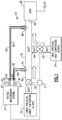
Figure 1 shows a first system for monitoring valve health. -
Figure 2 shows a second embodiment system for monitoring valve health. -
Figure 3 shows a third embodiment system for monitoring valve health. -
Figure 1 shows a firstembodiment ducting system 20. Afirst air source 22 is at a relatively low pressure and temperature. A second air source 24 is at a relatively higher pressure and higher temperature than the pressure and temperature offirst air source 22. Asink 26 receives a mixture of air from thesources 22 and 24. - One application of the
sink 26 is for air frame purposes on an aircraft. As known, aircraft have any number of systems which require air at a desired pressure and temperature. These are identified as USE in the Figures. -
Control 27 communicates with afirst valve 28 controlling the flow from thefirst air source 22 into aduct 30 at anupstream location 32. Thecontrol 27 also controls asecond valve 42 for supplying air from the second air source 24 into theduct 30 at adownstream location 44.Downstream location 44 is downstream of theupstream location 32 where the lower pressure/temperature source 22 enters theduct 30. The air is then passed to thesink 26 at anend location 46 of theduct 30. - In other embodiments the upstream location can be connected to the higher pressure/temperature source 24, with the downstream location connected to the lower pressure/
temperature source 22. -
Control 27 is programmed as known to control thevalves sink 26. -
Control 27 is also shown communicating withvoltage measurement system 41. Ajunction 40 receives signals from afirst temperature sensor 34, which is at a location intermediate theupstream location 32 and thedownstream location 44. Thus,temperature sensor 34 is sensing the temperature of the air supplied only from thefirst source 22. - A
second temperature sensor 48 is located downstream of thelocation 44, and intermediate thedownstream location 44 and theend location 46. As such,sensor 48 will measure the temperature of what might be a mixed air flow. -
Control 27 may close one of the twovalves Control 27 will be able to calculate a predicted temperature difference that should exist between the temperatures sensed at 34 and 48 based upon the status of thevalves valves - In one embodiment, the
sensors -
Sensor 34 has a pair of wires, afirst wire 36 that may be alumel and asecond wire 38 that may be chromel. These two wires are communicated tojunction 40. - The
sensor 48 also communicates through a pair of wires, awire 50, which may be alumel, and awire 52, which may be chromel. - All four wires transition to
copper wires 91 atpoints 93 withinjunction 40. - One of the two voltage signals supplied to the
system 41 can then be subtracted from the other, and a difference identified. Thecontrol 27 can utilize that difference to predict whether thevalves valves 28/42 may not be operating properly. As an example, should thevalve 42 be properly closed and there is a significant difference between the temperatures sensed bysensors valve 42 may be improperly open. Conversely, if thevalve 28 is intended to be closed, but the difference sensed bysensors valve 28 is not operating properly. As can be appreciated the predicted difference is determined based upon an intended position of thevalves - By comparing the temperature sensed by
sensors -
Figure 2 shows aducting system 60. Elements which are similar to thesystem 20 are identified by identical numbers. What is distinct from theFigure 1 embodiment here is thesensor 64 downstream ofdownstream location 44 now has analumel wire 66 and achromel wire 68, which each communicate to thesensor 62. In fact, those wires connect towires sensor 62 to themeasurement system 41. Based on the physics of thermocouple materials and, in particular, a phenomenon known as the Seebeck effect, the voltage ofwires sensors sensor 64 is different than the temperature fromsensor 62, then a voltage will be sensed and that voltage will be indicative of the amount of difference in the temperature sensed bysensors measurement system 41, greater accuracy is achieved. Of course,sensor 62 can send its pair of wires and signal tosensor 64. -
Figure 3 shows yet anotherembodiment 80. Thedownstream sensor 82 has analumel wire 84, which communicates as aconnection 88 to theupstream sensor 90.Sensor 82 has itsown chromel wire 92 extending to aconnection 93 with acopper wire 91 atjunction 40.Sensor 90 has itsown chromel wire 94 communicating to a copper wire C at junction A within a cold junction 86. - Essentially, there is a loop voltage on the entire circuit from one
wire 84/82 which will be representative of the net voltage difference corresponding to the different in temperature betweensensors - A ducting system under this disclosure could be said to include a first upstream location to be connected to a first source of air. A downstream location in the duct is to be connected to a second source of air. The upstream location has a first valve, and the downstream location has a second valve. An end location of the duct is to be connected to a sink. The first source of air and the second source of air will be at different temperature. A control is configured to control the first and second valve to achieve a desired pressure and temperature of air at the end location. The first temperature sensor is located at a position intermediate the upstream location and the downstream location. A second temperature sensor is located at a position intermediate the downstream location and the end location. A control is programmed to determine the health of the first and second valves based upon a difference between temperatures sensed by the first and second sensors. As to the term "intermediate" as used in this application, the two locations should be interpreted to include a sensor located at the location.
- A method of monitoring valve health under this disclosure could be said to include the steps of selectively connecting a first source of air at a first temperature through a first valve to a duct at a first upstream location. The method also includes the step of selectively connecting a second source of air at a second temperature distinct from the first temperature through a second valve to a downstream location in the duct. An end location of the duct is connected to a sink of air. The method includes the steps of controlling the first and second valve to achieve a desired pressure and temperature of air at the end location. The method includes the step of sensing a first temperature at a position intermediate the upstream location and the downstream location, and sensing a second temperature at a position intermediate the downstream location and the end location. A temperature difference between the first and second temperatures is determined. The health of the first and second valves is determined based upon a comparison of the difference between the first and second temperatures to a predicted temperature difference. The predicted temperature difference is based upon an intended position of the first valve and the second valve.
- The control may be any type of electronic controller programmed to achieve the disclosed features.
- While the specific temperature difference measurement systems as disclosed in this application may provide more accurate determination of the health of the first and second valves, the prior art temperature difference measurement systems may also be beneficial, and would benefit from the teachings of this disclosure.
- Although an embodiment of this invention has been disclosed, a worker of ordinary skill in this art would recognize that certain modifications would come within the scope of this disclosure. For that reason, the following claims should be studied to determine the true scope and content of this disclosure.
Claims (15)
- A ducting system comprising:a first upstream location in a duct to be connected to a first source of air (22);a downstream location in said duct to be connected to a second source of air;said upstream location having a first valve (28), and said downstream location having a second valve (42);an end location of said duct to be connected to a sink (26);a control configured for controlling said first and second valve to achieve a desired temperature of air at said end location; anda first temperature sensor (34) located at a position intermediate said upstream location and said downstream location, and a second temperature sensor located at a position intermediate said downstream location and said end location, and said control being programmed to determine the health of said first and second valves based upon a difference between temperatures sensed by said first and second sensors.
- The ducting system as set forth in claim 1, wherein the first source of air is at a first temperature, and the second source of air is at a second temperature, and said second temperature being higher than said first temperature, and optionally .wherein said difference between temperatures sensed by said first and second sensors is compared to a predicted temperature difference, said predicted temperature difference being based upon an intended position of said first valve and said second valve.
- The ducting system as set forth in claim 1 or 2, wherein each of said first and second sensors communicate to a measurement system through a pair of wires, said measurement system communicating to said control.
- The ducting system as set forth in claim 3, wherein one wire from each of said pair of wires from said first and second temperature sensors is alumel, and a second of said pair of wires from each of said first and second temperature sensors is chromel, and there is a connection between each of said alumel and chromel wires and an individual copper wire at a junction to said measurement system.
- The ducting system as set forth in claim 3, wherein both of said pair of wires from second temperature sensor communicate to said first temperature sensor, said pair of wires from said first temperature sensor extend to said measurement system, such that a temperature difference between the temperatures sensed at said first and second temperature sensors will be proportional to a voltage supplied by said pair of wires from said first temperature sensor to said measurement system, and optionally wherein one of said pair wires connecting said second temperature sensor to said first temperature sensor is chromel and a second of said wires connecting said second temperature sensor to said first temperature sensor is alumel.
- The ducting system as set forth in claim 3, wherein one of said pair of wires from each of said first and second temperature sensors communicates to a junction associated with said measurement system, and a second of said pair of wires of each of said first and second temperature sensors is a common wire that connects said second temperature sensor to said first temperature sensor, and optionally wherein said common wire is alumel, and said one wire communicating each of said downstream and upstream sensors to said measurement system is chromel.
- The ducting system as set forth in any preceding claim, wherein said first and second temperature sensors are thermocouple temperature sensors.
- An air use system comprising:a duct having a first upstream location connected to a first source of air;a downstream location in said duct connected to a second source of air;said first source communicating to said upstream location through a first valve, and said second source communicating to said downstream location through a second valve;an end location of said duct connected to a sink of air;said sink of air to be connected to a use for air on an aircraft;said first source of air and said second source of air being at different temperatures;a control configured for controlling said first and second valve to achieve a desired pressure and temperature of air at said end location; anda first temperature sensor located at a position intermediate said upstream location and said downstream location, and a second temperature sensor located at a position intermediate said downstream location and said end location, and said control for sensing a temperature difference between said temperature sensed by said first and second temperature sensor, and said control being programmed to determine the health of said first and second valves based upon a difference between said temperatures sensed by said first and second sensors.
- The air use system as set forth in claim 8, wherein each of said first and second sensors communicate to a measurement system through a pair of wires said measurement system communicating to said control.
- The air use system as set forth in claim 9, wherein one wire from each of said pair of wires from said first and second temperature sensors is alumel, and a second of said pair of wires from each of said first and second temperature sensors is chromel, and there is a connection between each of said alumel and chromel wires and an individual copper wire at a junction to said measurement system.
- The air use system as set forth in claim 9, wherein both of said pair of wires from second temperature sensor communicate to said first temperature sensor, said pair of wires from said first temperature sensor extend to said measurement system, such that a temperature difference between the temperatures sensed at said first and second temperature sensors will be proportional to a voltage supplied by said pair of wires from said first temperature sensor to said measurement system, and optionally wherein one of said pair wires connecting said second temperature sensor to said first temperature sensor is chromel and a second of said wires connecting said second temperature sensor to said first temperature sensor is alumel.
- The air use system as set forth in claim 9, wherein one of said pair of wires from each of said first and second temperature sensors communicates to a junction associated with said measurement system, and a second of said pair of wires of each of said first and second temperature sensors is a common wire that connects said second temperature sensor to said first temperature sensor.
- The air use system as set forth in claim 12, wherein said common wire is alumel, and said one wire communicating each of said downstream and upstream sensors to said measurement system is chromel, and optionally wherein said first and second temperature sensors are thermocouple temperature sensors.
- The air use system as set forth in any of claims 8 to 13, wherein said difference between temperatures sensed by said first and second sensors is compared to a predicted temperature difference, said predicted temperature difference being based upon an intended position of said first valve and said second valve.
- A method of monitoring valve health comprising the steps of:selectively connecting a first source of air at a first temperature through a first valve to a duct at a first upstream location;selectively connecting a second source of air at a second temperature distinct from said first temperature through a second valve to a downstream location in said duct;connecting an end location of said duct to a sink of air;controlling said first and second valve to achieve a desired pressure and temperature of air at said end location; andsensing a first temperature at a position intermediate said upstream location and said downstream location, and sensing a second temperature at a position intermediate said downstream location and said end location, and determining a temperature difference between said first and second temperatures, and determining the health of said first and second valves based upon a comparison of said difference between said first and second temperatures to a predicted temperature difference, said predicted temperature difference being based upon an intended position of said first valve and said second valve.
Applications Claiming Priority (1)
| Application Number | Priority Date | Filing Date | Title |
|---|---|---|---|
| US16/692,469 US11287154B2 (en) | 2019-11-22 | 2019-11-22 | Ducting system with valve health monitor |
Publications (2)
| Publication Number | Publication Date |
|---|---|
| EP3825809A1 true EP3825809A1 (en) | 2021-05-26 |
| EP3825809B1 EP3825809B1 (en) | 2023-12-27 |
Family
ID=73476058
Family Applications (1)
| Application Number | Title | Priority Date | Filing Date |
|---|---|---|---|
| EP20208482.8A Active EP3825809B1 (en) | 2019-11-22 | 2020-11-18 | Ducting system with valve health monitor |
Country Status (2)
| Country | Link |
|---|---|
| US (1) | US11287154B2 (en) |
| EP (1) | EP3825809B1 (en) |
Citations (3)
| Publication number | Priority date | Publication date | Assignee | Title |
|---|---|---|---|---|
| US20150251766A1 (en) * | 2014-03-10 | 2015-09-10 | The Boeing Company | Turbo-Compressor System and Method for Extracting Energy from an Aircraft Engine |
| EP3165462A1 (en) * | 2015-11-06 | 2017-05-10 | BAE Systems PLC | Aircraft environmental control system |
| US20190309683A1 (en) * | 2018-04-09 | 2019-10-10 | The Boeing Company | Bleed air systems for use with aircraft and related methods |
Family Cites Families (8)
| Publication number | Priority date | Publication date | Assignee | Title |
|---|---|---|---|---|
| US3921435A (en) | 1973-10-12 | 1975-11-25 | Exxon Production Research Co | Apparatus for detecting valve failure in a reciprocating pump |
| US3902315A (en) | 1974-06-12 | 1975-09-02 | United Aircraft Corp | Starting fuel control system for gas turbine engines |
| US4164172A (en) * | 1978-02-23 | 1979-08-14 | Energy Controls, Inc. | Method and apparatus for ventilating an occupied space |
| US5067094A (en) | 1989-04-13 | 1991-11-19 | Combustion Engineering, Inc. | Quantifying isolation valve leakage |
| DE19632059C2 (en) * | 1996-08-09 | 1999-10-14 | Mannesmann Vdo Ag | Method and arrangement for mixed air control of a heating / air conditioning system of a motor vehicle |
| US11814821B2 (en) | 2011-01-03 | 2023-11-14 | Sentinel Hydrosolutions, Llc | Non-invasive thermal dispersion flow meter with fluid leak detection and geo-fencing control |
| FR3015667A1 (en) | 2013-12-20 | 2015-06-26 | Sc2N Sa | DEVICE FOR MEASURING A TEMPERATURE DIFFERENTIAL |
| US11573130B2 (en) * | 2019-11-22 | 2023-02-07 | Hamilton Sundstrand Corporation | Temperature difference measurement system |
-
2019
- 2019-11-22 US US16/692,469 patent/US11287154B2/en active Active
-
2020
- 2020-11-18 EP EP20208482.8A patent/EP3825809B1/en active Active
Patent Citations (3)
| Publication number | Priority date | Publication date | Assignee | Title |
|---|---|---|---|---|
| US20150251766A1 (en) * | 2014-03-10 | 2015-09-10 | The Boeing Company | Turbo-Compressor System and Method for Extracting Energy from an Aircraft Engine |
| EP3165462A1 (en) * | 2015-11-06 | 2017-05-10 | BAE Systems PLC | Aircraft environmental control system |
| US20190309683A1 (en) * | 2018-04-09 | 2019-10-10 | The Boeing Company | Bleed air systems for use with aircraft and related methods |
Also Published As
| Publication number | Publication date |
|---|---|
| US20210156581A1 (en) | 2021-05-27 |
| US11287154B2 (en) | 2022-03-29 |
| EP3825809B1 (en) | 2023-12-27 |
Similar Documents
| Publication | Publication Date | Title |
|---|---|---|
| US11860044B2 (en) | Temperature difference measurement system | |
| JP5847106B2 (en) | Pressure flow control device with flow monitor. | |
| KR101444964B1 (en) | Flow controller, flow measuring device testing method, flow controller testing system, and semiconductor manufacturing apparatus | |
| US10883866B2 (en) | Pressure-based flow rate control device and malfunction detection method therefor | |
| TWI731159B (en) | Flow rate control device, program recording medium storing program for flow rate control device, and flow rate control method | |
| US9846074B2 (en) | System for and method of monitoring flow through mass flow controllers in real time | |
| US6205409B1 (en) | Predictive failure monitoring system for a mass flow controller | |
| EP3483690B1 (en) | A method for controlling a fluid flow through a valve | |
| US20170364099A1 (en) | Flow control system with build-down system flow monitoring | |
| AU2020395466B2 (en) | A valve for adjusting a fluid flow and methods for use in connection with such a valve | |
| US20140083673A1 (en) | Device and method for controlling opening of a valve in an hvac system | |
| JPWO2009084422A1 (en) | Flow rate ratio controller | |
| CA2977630C (en) | Device and method for mixing combustible gas and combustion air, hot water installation provided therewith, corresponding thermal mass flow sensor and method for measuring a mass flow rate of a gas flow | |
| EP0110325A1 (en) | Flow rate control system | |
| US10895484B2 (en) | Gas supply device capable of measuring flow rate, flowmeter, and flow rate measuring method | |
| EP3105647B1 (en) | System for and method of providing pressure insensitive self verifying mass flow controller | |
| KR20140135650A (en) | Metrology method for transient gas flow | |
| EP3825809B1 (en) | Ducting system with valve health monitor | |
| CZ2015399A3 (en) | Connection to the system for performance management and diagnostics of the heat exchanger | |
| CN109564119A (en) | Pressure flow-rate controller, its flow calculation method and flow control methods | |
| US20220147069A1 (en) | Gas safety device | |
| JPH0199108A (en) | Control device | |
| IT202300009297A1 (en) | CONVERSION DEVICE FOR DISPENSER | |
| CS235683B1 (en) | Equipment for measurement and regulation of gas mass flow |
Legal Events
| Date | Code | Title | Description |
|---|---|---|---|
| PUAI | Public reference made under article 153(3) epc to a published international application that has entered the european phase |
Free format text: ORIGINAL CODE: 0009012 |
|
| STAA | Information on the status of an ep patent application or granted ep patent |
Free format text: STATUS: THE APPLICATION HAS BEEN PUBLISHED |
|
| AK | Designated contracting states |
Kind code of ref document: A1 Designated state(s): AL AT BE BG CH CY CZ DE DK EE ES FI FR GB GR HR HU IE IS IT LI LT LU LV MC MK MT NL NO PL PT RO RS SE SI SK SM TR |
|
| STAA | Information on the status of an ep patent application or granted ep patent |
Free format text: STATUS: REQUEST FOR EXAMINATION WAS MADE |
|
| 17P | Request for examination filed |
Effective date: 20211124 |
|
| RBV | Designated contracting states (corrected) |
Designated state(s): AL AT BE BG CH CY CZ DE DK EE ES FI FR GB GR HR HU IE IS IT LI LT LU LV MC MK MT NL NO PL PT RO RS SE SI SK SM TR |
|
| GRAP | Despatch of communication of intention to grant a patent |
Free format text: ORIGINAL CODE: EPIDOSNIGR1 |
|
| STAA | Information on the status of an ep patent application or granted ep patent |
Free format text: STATUS: GRANT OF PATENT IS INTENDED |
|
| INTG | Intention to grant announced |
Effective date: 20230705 |
|
| GRAS | Grant fee paid |
Free format text: ORIGINAL CODE: EPIDOSNIGR3 |
|
| GRAA | (expected) grant |
Free format text: ORIGINAL CODE: 0009210 |
|
| STAA | Information on the status of an ep patent application or granted ep patent |
Free format text: STATUS: THE PATENT HAS BEEN GRANTED |
|
| AK | Designated contracting states |
Kind code of ref document: B1 Designated state(s): AL AT BE BG CH CY CZ DE DK EE ES FI FR GB GR HR HU IE IS IT LI LT LU LV MC MK MT NL NO PL PT RO RS SE SI SK SM TR |
|
| REG | Reference to a national code |
Ref country code: GB Ref legal event code: FG4D |
|
| REG | Reference to a national code |
Ref country code: CH Ref legal event code: EP |
|
| REG | Reference to a national code |
Ref country code: DE Ref legal event code: R096 Ref document number: 602020023321 Country of ref document: DE |
|
| REG | Reference to a national code |
Ref country code: IE Ref legal event code: FG4D |
|
| PG25 | Lapsed in a contracting state [announced via postgrant information from national office to epo] |
Ref country code: GR Free format text: LAPSE BECAUSE OF FAILURE TO SUBMIT A TRANSLATION OF THE DESCRIPTION OR TO PAY THE FEE WITHIN THE PRESCRIBED TIME-LIMIT Effective date: 20240328 |
|
| REG | Reference to a national code |
Ref country code: LT Ref legal event code: MG9D |
|
| PG25 | Lapsed in a contracting state [announced via postgrant information from national office to epo] |
Ref country code: LT Free format text: LAPSE BECAUSE OF FAILURE TO SUBMIT A TRANSLATION OF THE DESCRIPTION OR TO PAY THE FEE WITHIN THE PRESCRIBED TIME-LIMIT Effective date: 20231227 |
|
| PG25 | Lapsed in a contracting state [announced via postgrant information from national office to epo] |
Ref country code: ES Free format text: LAPSE BECAUSE OF FAILURE TO SUBMIT A TRANSLATION OF THE DESCRIPTION OR TO PAY THE FEE WITHIN THE PRESCRIBED TIME-LIMIT Effective date: 20231227 |
|
| PG25 | Lapsed in a contracting state [announced via postgrant information from national office to epo] |
Ref country code: LT Free format text: LAPSE BECAUSE OF FAILURE TO SUBMIT A TRANSLATION OF THE DESCRIPTION OR TO PAY THE FEE WITHIN THE PRESCRIBED TIME-LIMIT Effective date: 20231227 Ref country code: GR Free format text: LAPSE BECAUSE OF FAILURE TO SUBMIT A TRANSLATION OF THE DESCRIPTION OR TO PAY THE FEE WITHIN THE PRESCRIBED TIME-LIMIT Effective date: 20240328 Ref country code: FI Free format text: LAPSE BECAUSE OF FAILURE TO SUBMIT A TRANSLATION OF THE DESCRIPTION OR TO PAY THE FEE WITHIN THE PRESCRIBED TIME-LIMIT Effective date: 20231227 Ref country code: ES Free format text: LAPSE BECAUSE OF FAILURE TO SUBMIT A TRANSLATION OF THE DESCRIPTION OR TO PAY THE FEE WITHIN THE PRESCRIBED TIME-LIMIT Effective date: 20231227 Ref country code: BG Free format text: LAPSE BECAUSE OF FAILURE TO SUBMIT A TRANSLATION OF THE DESCRIPTION OR TO PAY THE FEE WITHIN THE PRESCRIBED TIME-LIMIT Effective date: 20240327 |
|
| REG | Reference to a national code |
Ref country code: NL Ref legal event code: MP Effective date: 20231227 |
|
| REG | Reference to a national code |
Ref country code: AT Ref legal event code: MK05 Ref document number: 1645127 Country of ref document: AT Kind code of ref document: T Effective date: 20231227 |
|
| PG25 | Lapsed in a contracting state [announced via postgrant information from national office to epo] |
Ref country code: NL Free format text: LAPSE BECAUSE OF FAILURE TO SUBMIT A TRANSLATION OF THE DESCRIPTION OR TO PAY THE FEE WITHIN THE PRESCRIBED TIME-LIMIT Effective date: 20231227 |
|
| PG25 | Lapsed in a contracting state [announced via postgrant information from national office to epo] |
Ref country code: SE Free format text: LAPSE BECAUSE OF FAILURE TO SUBMIT A TRANSLATION OF THE DESCRIPTION OR TO PAY THE FEE WITHIN THE PRESCRIBED TIME-LIMIT Effective date: 20231227 Ref country code: RS Free format text: LAPSE BECAUSE OF FAILURE TO SUBMIT A TRANSLATION OF THE DESCRIPTION OR TO PAY THE FEE WITHIN THE PRESCRIBED TIME-LIMIT Effective date: 20231227 Ref country code: NO Free format text: LAPSE BECAUSE OF FAILURE TO SUBMIT A TRANSLATION OF THE DESCRIPTION OR TO PAY THE FEE WITHIN THE PRESCRIBED TIME-LIMIT Effective date: 20240327 Ref country code: NL Free format text: LAPSE BECAUSE OF FAILURE TO SUBMIT A TRANSLATION OF THE DESCRIPTION OR TO PAY THE FEE WITHIN THE PRESCRIBED TIME-LIMIT Effective date: 20231227 Ref country code: LV Free format text: LAPSE BECAUSE OF FAILURE TO SUBMIT A TRANSLATION OF THE DESCRIPTION OR TO PAY THE FEE WITHIN THE PRESCRIBED TIME-LIMIT Effective date: 20231227 Ref country code: HR Free format text: LAPSE BECAUSE OF FAILURE TO SUBMIT A TRANSLATION OF THE DESCRIPTION OR TO PAY THE FEE WITHIN THE PRESCRIBED TIME-LIMIT Effective date: 20231227 |
|
| PG25 | Lapsed in a contracting state [announced via postgrant information from national office to epo] |
Ref country code: IS Free format text: LAPSE BECAUSE OF FAILURE TO SUBMIT A TRANSLATION OF THE DESCRIPTION OR TO PAY THE FEE WITHIN THE PRESCRIBED TIME-LIMIT Effective date: 20240427 |
|
| PG25 | Lapsed in a contracting state [announced via postgrant information from national office to epo] |
Ref country code: AT Free format text: LAPSE BECAUSE OF FAILURE TO SUBMIT A TRANSLATION OF THE DESCRIPTION OR TO PAY THE FEE WITHIN THE PRESCRIBED TIME-LIMIT Effective date: 20231227 Ref country code: CZ Free format text: LAPSE BECAUSE OF FAILURE TO SUBMIT A TRANSLATION OF THE DESCRIPTION OR TO PAY THE FEE WITHIN THE PRESCRIBED TIME-LIMIT Effective date: 20231227 |
|
| PG25 | Lapsed in a contracting state [announced via postgrant information from national office to epo] |
Ref country code: SK Free format text: LAPSE BECAUSE OF FAILURE TO SUBMIT A TRANSLATION OF THE DESCRIPTION OR TO PAY THE FEE WITHIN THE PRESCRIBED TIME-LIMIT Effective date: 20231227 |
|
| PG25 | Lapsed in a contracting state [announced via postgrant information from national office to epo] |
Ref country code: SM Free format text: LAPSE BECAUSE OF FAILURE TO SUBMIT A TRANSLATION OF THE DESCRIPTION OR TO PAY THE FEE WITHIN THE PRESCRIBED TIME-LIMIT Effective date: 20231227 Ref country code: SK Free format text: LAPSE BECAUSE OF FAILURE TO SUBMIT A TRANSLATION OF THE DESCRIPTION OR TO PAY THE FEE WITHIN THE PRESCRIBED TIME-LIMIT Effective date: 20231227 Ref country code: RO Free format text: LAPSE BECAUSE OF FAILURE TO SUBMIT A TRANSLATION OF THE DESCRIPTION OR TO PAY THE FEE WITHIN THE PRESCRIBED TIME-LIMIT Effective date: 20231227 Ref country code: IT Free format text: LAPSE BECAUSE OF FAILURE TO SUBMIT A TRANSLATION OF THE DESCRIPTION OR TO PAY THE FEE WITHIN THE PRESCRIBED TIME-LIMIT Effective date: 20231227 Ref country code: IS Free format text: LAPSE BECAUSE OF FAILURE TO SUBMIT A TRANSLATION OF THE DESCRIPTION OR TO PAY THE FEE WITHIN THE PRESCRIBED TIME-LIMIT Effective date: 20240427 Ref country code: EE Free format text: LAPSE BECAUSE OF FAILURE TO SUBMIT A TRANSLATION OF THE DESCRIPTION OR TO PAY THE FEE WITHIN THE PRESCRIBED TIME-LIMIT Effective date: 20231227 Ref country code: CZ Free format text: LAPSE BECAUSE OF FAILURE TO SUBMIT A TRANSLATION OF THE DESCRIPTION OR TO PAY THE FEE WITHIN THE PRESCRIBED TIME-LIMIT Effective date: 20231227 Ref country code: AT Free format text: LAPSE BECAUSE OF FAILURE TO SUBMIT A TRANSLATION OF THE DESCRIPTION OR TO PAY THE FEE WITHIN THE PRESCRIBED TIME-LIMIT Effective date: 20231227 |
|
| PG25 | Lapsed in a contracting state [announced via postgrant information from national office to epo] |
Ref country code: PT Free format text: LAPSE BECAUSE OF FAILURE TO SUBMIT A TRANSLATION OF THE DESCRIPTION OR TO PAY THE FEE WITHIN THE PRESCRIBED TIME-LIMIT Effective date: 20240429 Ref country code: PL Free format text: LAPSE BECAUSE OF FAILURE TO SUBMIT A TRANSLATION OF THE DESCRIPTION OR TO PAY THE FEE WITHIN THE PRESCRIBED TIME-LIMIT Effective date: 20231227 |
|
| PG25 | Lapsed in a contracting state [announced via postgrant information from national office to epo] |
Ref country code: PT Free format text: LAPSE BECAUSE OF FAILURE TO SUBMIT A TRANSLATION OF THE DESCRIPTION OR TO PAY THE FEE WITHIN THE PRESCRIBED TIME-LIMIT Effective date: 20240429 Ref country code: PL Free format text: LAPSE BECAUSE OF FAILURE TO SUBMIT A TRANSLATION OF THE DESCRIPTION OR TO PAY THE FEE WITHIN THE PRESCRIBED TIME-LIMIT Effective date: 20231227 |
|
| REG | Reference to a national code |
Ref country code: DE Ref legal event code: R097 Ref document number: 602020023321 Country of ref document: DE |
|
| PG25 | Lapsed in a contracting state [announced via postgrant information from national office to epo] |
Ref country code: DK Free format text: LAPSE BECAUSE OF FAILURE TO SUBMIT A TRANSLATION OF THE DESCRIPTION OR TO PAY THE FEE WITHIN THE PRESCRIBED TIME-LIMIT Effective date: 20231227 |
|
| PG25 | Lapsed in a contracting state [announced via postgrant information from national office to epo] |
Ref country code: DK Free format text: LAPSE BECAUSE OF FAILURE TO SUBMIT A TRANSLATION OF THE DESCRIPTION OR TO PAY THE FEE WITHIN THE PRESCRIBED TIME-LIMIT Effective date: 20231227 |
|
| PLBE | No opposition filed within time limit |
Free format text: ORIGINAL CODE: 0009261 |
|
| STAA | Information on the status of an ep patent application or granted ep patent |
Free format text: STATUS: NO OPPOSITION FILED WITHIN TIME LIMIT |
|
| 26N | No opposition filed |
Effective date: 20240930 |
|
| PG25 | Lapsed in a contracting state [announced via postgrant information from national office to epo] |
Ref country code: SI Free format text: LAPSE BECAUSE OF FAILURE TO SUBMIT A TRANSLATION OF THE DESCRIPTION OR TO PAY THE FEE WITHIN THE PRESCRIBED TIME-LIMIT Effective date: 20231227 |
|
| REG | Reference to a national code |
Ref country code: CH Ref legal event code: PL |
|
| PG25 | Lapsed in a contracting state [announced via postgrant information from national office to epo] |
Ref country code: MC Free format text: LAPSE BECAUSE OF FAILURE TO SUBMIT A TRANSLATION OF THE DESCRIPTION OR TO PAY THE FEE WITHIN THE PRESCRIBED TIME-LIMIT Effective date: 20231227 |
|
| PG25 | Lapsed in a contracting state [announced via postgrant information from national office to epo] |
Ref country code: LU Free format text: LAPSE BECAUSE OF NON-PAYMENT OF DUE FEES Effective date: 20241118 |
|
| REG | Reference to a national code |
Ref country code: CH Ref legal event code: PL |
|
| PG25 | Lapsed in a contracting state [announced via postgrant information from national office to epo] |
Ref country code: CH Free format text: LAPSE BECAUSE OF NON-PAYMENT OF DUE FEES Effective date: 20241130 |
|
| REG | Reference to a national code |
Ref country code: BE Ref legal event code: MM Effective date: 20241130 |
|
| PG25 | Lapsed in a contracting state [announced via postgrant information from national office to epo] |
Ref country code: BE Free format text: LAPSE BECAUSE OF NON-PAYMENT OF DUE FEES Effective date: 20241130 |
|
| PG25 | Lapsed in a contracting state [announced via postgrant information from national office to epo] |
Ref country code: IE Free format text: LAPSE BECAUSE OF NON-PAYMENT OF DUE FEES Effective date: 20241118 |
|
| PGFP | Annual fee paid to national office [announced via postgrant information from national office to epo] |
Ref country code: DE Payment date: 20251022 Year of fee payment: 6 |
|
| PGFP | Annual fee paid to national office [announced via postgrant information from national office to epo] |
Ref country code: GB Payment date: 20251023 Year of fee payment: 6 |
|
| PGFP | Annual fee paid to national office [announced via postgrant information from national office to epo] |
Ref country code: FR Payment date: 20251023 Year of fee payment: 6 |
|
| P01 | Opt-out of the competence of the unified patent court (upc) registered |
Free format text: CASE NUMBER: UPC_APP_0018792_3825809/2025 Effective date: 20251221 |
|
| PG25 | Lapsed in a contracting state [announced via postgrant information from national office to epo] |
Ref country code: HU Free format text: LAPSE BECAUSE OF FAILURE TO SUBMIT A TRANSLATION OF THE DESCRIPTION OR TO PAY THE FEE WITHIN THE PRESCRIBED TIME-LIMIT; INVALID AB INITIO Effective date: 20201118 |
|
| PG25 | Lapsed in a contracting state [announced via postgrant information from national office to epo] |
Ref country code: CY Free format text: LAPSE BECAUSE OF FAILURE TO SUBMIT A TRANSLATION OF THE DESCRIPTION OR TO PAY THE FEE WITHIN THE PRESCRIBED TIME-LIMIT; INVALID AB INITIO Effective date: 20201118 |