EP3825679A1 - Method for estimating sulfur component concentration in gasoline - Google Patents
Method for estimating sulfur component concentration in gasoline Download PDFInfo
- Publication number
- EP3825679A1 EP3825679A1 EP20206853.2A EP20206853A EP3825679A1 EP 3825679 A1 EP3825679 A1 EP 3825679A1 EP 20206853 A EP20206853 A EP 20206853A EP 3825679 A1 EP3825679 A1 EP 3825679A1
- Authority
- EP
- European Patent Office
- Prior art keywords
- gasoline
- sulfur
- component concentration
- sensor unit
- refractive index
- Prior art date
- Legal status (The legal status is an assumption and is not a legal conclusion. Google has not performed a legal analysis and makes no representation as to the accuracy of the status listed.)
- Withdrawn
Links
- NINIDFKCEFEMDL-UHFFFAOYSA-N Sulfur Chemical compound [S] NINIDFKCEFEMDL-UHFFFAOYSA-N 0.000 title claims abstract description 78
- 229910052717 sulfur Inorganic materials 0.000 title claims abstract description 78
- 239000011593 sulfur Substances 0.000 title claims abstract description 78
- 238000000034 method Methods 0.000 title claims abstract description 69
- 125000003118 aryl group Chemical group 0.000 claims abstract description 35
- 238000002309 gasification Methods 0.000 claims abstract description 17
- 239000000835 fiber Substances 0.000 claims description 76
- 239000013307 optical fiber Substances 0.000 claims description 44
- 239000003054 catalyst Substances 0.000 claims description 36
- FCEHBMOGCRZNNI-UHFFFAOYSA-N 1-benzothiophene Chemical compound C1=CC=C2SC=CC2=C1 FCEHBMOGCRZNNI-UHFFFAOYSA-N 0.000 claims description 28
- XTQHKBHJIVJGKJ-UHFFFAOYSA-N sulfur monoxide Chemical class S=O XTQHKBHJIVJGKJ-UHFFFAOYSA-N 0.000 claims description 25
- 229910052815 sulfur oxide Inorganic materials 0.000 claims description 21
- 238000002485 combustion reaction Methods 0.000 claims description 16
- YXFVVABEGXRONW-UHFFFAOYSA-N Toluene Chemical compound CC1=CC=CC=C1 YXFVVABEGXRONW-UHFFFAOYSA-N 0.000 claims description 15
- 239000000463 material Substances 0.000 claims description 8
- IYYZUPMFVPLQIF-UHFFFAOYSA-N dibenzothiophene Chemical compound C1=CC=C2C3=CC=CC=C3SC2=C1 IYYZUPMFVPLQIF-UHFFFAOYSA-N 0.000 claims description 6
- TXKMVPPZCYKFAC-UHFFFAOYSA-N disulfur monoxide Inorganic materials O=S=S TXKMVPPZCYKFAC-UHFFFAOYSA-N 0.000 claims description 5
- 239000002574 poison Substances 0.000 claims description 4
- 231100000614 poison Toxicity 0.000 claims description 4
- BZYUMXXOAYSFOW-UHFFFAOYSA-N 2,3-dimethylthiophene Chemical compound CC=1C=CSC=1C BZYUMXXOAYSFOW-UHFFFAOYSA-N 0.000 claims description 3
- 239000007789 gas Substances 0.000 description 45
- 239000011162 core material Substances 0.000 description 22
- 239000007788 liquid Substances 0.000 description 18
- 238000005259 measurement Methods 0.000 description 15
- 238000000746 purification Methods 0.000 description 8
- MWUXSHHQAYIFBG-UHFFFAOYSA-N nitrogen oxide Inorganic materials O=[N] MWUXSHHQAYIFBG-UHFFFAOYSA-N 0.000 description 7
- 238000005253 cladding Methods 0.000 description 6
- 230000000052 comparative effect Effects 0.000 description 5
- 231100000572 poisoning Toxicity 0.000 description 5
- 230000000607 poisoning effect Effects 0.000 description 5
- 229920006395 saturated elastomer Polymers 0.000 description 5
- 230000001902 propagating effect Effects 0.000 description 3
- 239000013076 target substance Substances 0.000 description 3
- UGFAIRIUMAVXCW-UHFFFAOYSA-N Carbon monoxide Chemical compound [O+]#[C-] UGFAIRIUMAVXCW-UHFFFAOYSA-N 0.000 description 2
- 239000003463 adsorbent Substances 0.000 description 2
- 150000001335 aliphatic alkanes Chemical class 0.000 description 2
- 229910002091 carbon monoxide Inorganic materials 0.000 description 2
- 238000010586 diagram Methods 0.000 description 2
- 239000000446 fuel Substances 0.000 description 2
- 238000010438 heat treatment Methods 0.000 description 2
- 229930195733 hydrocarbon Natural products 0.000 description 2
- 150000002430 hydrocarbons Chemical class 0.000 description 2
- 238000011084 recovery Methods 0.000 description 2
- LIKMAJRDDDTEIG-UHFFFAOYSA-N 1-hexene Chemical compound CCCCC=C LIKMAJRDDDTEIG-UHFFFAOYSA-N 0.000 description 1
- -1 Benzothiophene Toluene Hexene Hexane Chemical compound 0.000 description 1
- 238000004566 IR spectroscopy Methods 0.000 description 1
- VCUFZILGIRCDQQ-KRWDZBQOSA-N N-[[(5S)-2-oxo-3-(2-oxo-3H-1,3-benzoxazol-6-yl)-1,3-oxazolidin-5-yl]methyl]-2-[[3-(trifluoromethoxy)phenyl]methylamino]pyrimidine-5-carboxamide Chemical compound O=C1O[C@H](CN1C1=CC2=C(NC(O2)=O)C=C1)CNC(=O)C=1C=NC(=NC=1)NCC1=CC(=CC=C1)OC(F)(F)F VCUFZILGIRCDQQ-KRWDZBQOSA-N 0.000 description 1
- 238000010521 absorption reaction Methods 0.000 description 1
- 150000001491 aromatic compounds Chemical class 0.000 description 1
- 238000004587 chromatography analysis Methods 0.000 description 1
- 150000001875 compounds Chemical class 0.000 description 1
- 238000010276 construction Methods 0.000 description 1
- 230000000694 effects Effects 0.000 description 1
- 238000012986 modification Methods 0.000 description 1
- 230000004048 modification Effects 0.000 description 1
- TVMXDCGIABBOFY-UHFFFAOYSA-N octane Chemical compound CCCCCCCC TVMXDCGIABBOFY-UHFFFAOYSA-N 0.000 description 1
- 230000003287 optical effect Effects 0.000 description 1
- 230000002093 peripheral effect Effects 0.000 description 1
- 238000001228 spectrum Methods 0.000 description 1
- 125000004434 sulfur atom Chemical group 0.000 description 1
Images


Classifications
-
- G—PHYSICS
- G01—MEASURING; TESTING
- G01N—INVESTIGATING OR ANALYSING MATERIALS BY DETERMINING THEIR CHEMICAL OR PHYSICAL PROPERTIES
- G01N21/00—Investigating or analysing materials by the use of optical means, i.e. using sub-millimetre waves, infrared, visible or ultraviolet light
- G01N21/17—Systems in which incident light is modified in accordance with the properties of the material investigated
- G01N21/41—Refractivity; Phase-affecting properties, e.g. optical path length
- G01N21/4133—Refractometers, e.g. differential
-
- B—PERFORMING OPERATIONS; TRANSPORTING
- B01—PHYSICAL OR CHEMICAL PROCESSES OR APPARATUS IN GENERAL
- B01J—CHEMICAL OR PHYSICAL PROCESSES, e.g. CATALYSIS OR COLLOID CHEMISTRY; THEIR RELEVANT APPARATUS
- B01J38/00—Regeneration or reactivation of catalysts, in general
-
- G—PHYSICS
- G01—MEASURING; TESTING
- G01N—INVESTIGATING OR ANALYSING MATERIALS BY DETERMINING THEIR CHEMICAL OR PHYSICAL PROPERTIES
- G01N21/00—Investigating or analysing materials by the use of optical means, i.e. using sub-millimetre waves, infrared, visible or ultraviolet light
- G01N21/17—Systems in which incident light is modified in accordance with the properties of the material investigated
- G01N21/41—Refractivity; Phase-affecting properties, e.g. optical path length
- G01N21/412—Index profiling of optical fibres
-
- G—PHYSICS
- G01—MEASURING; TESTING
- G01N—INVESTIGATING OR ANALYSING MATERIALS BY DETERMINING THEIR CHEMICAL OR PHYSICAL PROPERTIES
- G01N21/00—Investigating or analysing materials by the use of optical means, i.e. using sub-millimetre waves, infrared, visible or ultraviolet light
- G01N21/17—Systems in which incident light is modified in accordance with the properties of the material investigated
- G01N21/41—Refractivity; Phase-affecting properties, e.g. optical path length
-
- B—PERFORMING OPERATIONS; TRANSPORTING
- B01—PHYSICAL OR CHEMICAL PROCESSES OR APPARATUS IN GENERAL
- B01J—CHEMICAL OR PHYSICAL PROCESSES, e.g. CATALYSIS OR COLLOID CHEMISTRY; THEIR RELEVANT APPARATUS
- B01J38/00—Regeneration or reactivation of catalysts, in general
- B01J38/04—Gas or vapour treating; Treating by using liquids vaporisable upon contacting spent catalyst
-
- G—PHYSICS
- G01—MEASURING; TESTING
- G01N—INVESTIGATING OR ANALYSING MATERIALS BY DETERMINING THEIR CHEMICAL OR PHYSICAL PROPERTIES
- G01N1/00—Sampling; Preparing specimens for investigation
- G01N1/28—Preparing specimens for investigation including physical details of (bio-)chemical methods covered elsewhere, e.g. G01N33/50, C12Q
- G01N1/40—Concentrating samples
- G01N1/4022—Concentrating samples by thermal techniques; Phase changes
-
- G—PHYSICS
- G01—MEASURING; TESTING
- G01N—INVESTIGATING OR ANALYSING MATERIALS BY DETERMINING THEIR CHEMICAL OR PHYSICAL PROPERTIES
- G01N1/00—Sampling; Preparing specimens for investigation
- G01N1/28—Preparing specimens for investigation including physical details of (bio-)chemical methods covered elsewhere, e.g. G01N33/50, C12Q
- G01N1/44—Sample treatment involving radiation, e.g. heat
-
- G—PHYSICS
- G01—MEASURING; TESTING
- G01N—INVESTIGATING OR ANALYSING MATERIALS BY DETERMINING THEIR CHEMICAL OR PHYSICAL PROPERTIES
- G01N21/00—Investigating or analysing materials by the use of optical means, i.e. using sub-millimetre waves, infrared, visible or ultraviolet light
- G01N21/17—Systems in which incident light is modified in accordance with the properties of the material investigated
-
- G—PHYSICS
- G01—MEASURING; TESTING
- G01N—INVESTIGATING OR ANALYSING MATERIALS BY DETERMINING THEIR CHEMICAL OR PHYSICAL PROPERTIES
- G01N21/00—Investigating or analysing materials by the use of optical means, i.e. using sub-millimetre waves, infrared, visible or ultraviolet light
- G01N21/17—Systems in which incident light is modified in accordance with the properties of the material investigated
- G01N21/25—Colour; Spectral properties, i.e. comparison of effect of material on the light at two or more different wavelengths or wavelength bands
- G01N21/31—Investigating relative effect of material at wavelengths characteristic of specific elements or molecules, e.g. atomic absorption spectrometry
- G01N21/39—Investigating relative effect of material at wavelengths characteristic of specific elements or molecules, e.g. atomic absorption spectrometry using tunable lasers
-
- G—PHYSICS
- G01—MEASURING; TESTING
- G01N—INVESTIGATING OR ANALYSING MATERIALS BY DETERMINING THEIR CHEMICAL OR PHYSICAL PROPERTIES
- G01N33/00—Investigating or analysing materials by specific methods not covered by groups G01N1/00 - G01N31/00
- G01N33/22—Fuels; Explosives
-
- G—PHYSICS
- G01—MEASURING; TESTING
- G01N—INVESTIGATING OR ANALYSING MATERIALS BY DETERMINING THEIR CHEMICAL OR PHYSICAL PROPERTIES
- G01N33/00—Investigating or analysing materials by specific methods not covered by groups G01N1/00 - G01N31/00
- G01N33/26—Oils; Viscous liquids; Paints; Inks
- G01N33/28—Oils, i.e. hydrocarbon liquids
- G01N33/2835—Specific substances contained in the oils or fuels
- G01N33/287—Sulfur content
-
- G—PHYSICS
- G01—MEASURING; TESTING
- G01N—INVESTIGATING OR ANALYSING MATERIALS BY DETERMINING THEIR CHEMICAL OR PHYSICAL PROPERTIES
- G01N1/00—Sampling; Preparing specimens for investigation
- G01N1/28—Preparing specimens for investigation including physical details of (bio-)chemical methods covered elsewhere, e.g. G01N33/50, C12Q
- G01N1/40—Concentrating samples
- G01N1/4022—Concentrating samples by thermal techniques; Phase changes
- G01N2001/4027—Concentrating samples by thermal techniques; Phase changes evaporation leaving a concentrated sample
-
- G—PHYSICS
- G01—MEASURING; TESTING
- G01N—INVESTIGATING OR ANALYSING MATERIALS BY DETERMINING THEIR CHEMICAL OR PHYSICAL PROPERTIES
- G01N21/00—Investigating or analysing materials by the use of optical means, i.e. using sub-millimetre waves, infrared, visible or ultraviolet light
- G01N21/17—Systems in which incident light is modified in accordance with the properties of the material investigated
- G01N21/41—Refractivity; Phase-affecting properties, e.g. optical path length
- G01N2021/4173—Phase distribution
-
- G—PHYSICS
- G01—MEASURING; TESTING
- G01N—INVESTIGATING OR ANALYSING MATERIALS BY DETERMINING THEIR CHEMICAL OR PHYSICAL PROPERTIES
- G01N21/00—Investigating or analysing materials by the use of optical means, i.e. using sub-millimetre waves, infrared, visible or ultraviolet light
- G01N21/17—Systems in which incident light is modified in accordance with the properties of the material investigated
- G01N21/41—Refractivity; Phase-affecting properties, e.g. optical path length
- G01N21/43—Refractivity; Phase-affecting properties, e.g. optical path length by measuring critical angle
-
- G—PHYSICS
- G01—MEASURING; TESTING
- G01N—INVESTIGATING OR ANALYSING MATERIALS BY DETERMINING THEIR CHEMICAL OR PHYSICAL PROPERTIES
- G01N2201/00—Features of devices classified in G01N21/00
- G01N2201/06—Illumination; Optics
- G01N2201/061—Sources
- G01N2201/06113—Coherent sources; lasers
-
- G—PHYSICS
- G01—MEASURING; TESTING
- G01N—INVESTIGATING OR ANALYSING MATERIALS BY DETERMINING THEIR CHEMICAL OR PHYSICAL PROPERTIES
- G01N2201/00—Features of devices classified in G01N21/00
- G01N2201/08—Optical fibres; light guides
- G01N2201/088—Using a sensor fibre
Definitions
- the present disclosure relates to a method for estimating the concentration of sulfur components in gasoline.
- Methods for measuring a variety of liquid and gaseous components are known in the prior art. Examples of such methods include chromatographic methods and infrared spectroscopy. Other methods are known that use optical fiber sensors to measure the refractive indexes of liquids or gases, allowing target substances to be estimated.
- PTL 1 discloses a method for sensing gases in gasoline, the method employing an optical fiber device using optical fibers as the gas sensor.
- the optical fiber device described in PTL 1 is an optical fiber device comprising a sensor unit in the form of an optical fiber composed of a waveguide, and an optical fiber A and optical fiber B composed of a core and cladding, which are each optically connected to one or the other end of the sensor unit and situated on one side and the other side of the sensor unit, wherein the waveguide of the sensor unit is made of the same material as the core of the optical fiber A and optical fiber B, the dimension of the sensor unit in the radial direction is larger than the dimension of the core of the optical fiber A and the dimension of the core of the optical fiber B, and the sensor unit has at least one outer surface that is completely covered with an adsorbent.
- the components in a target substance can be detected based on the amount of Goos-Hänchen shift during total reflection at the boundary between the optical fiber and the adsorbent that is to adsorb the target substance, which is disposed on the outer peripheral side of the optical fiber sensor.
- Exhaust gas produced by combustion of fuel such as gasoline in an internal combustion engine such as an automobile gasoline engine contains components such as carbon monoxide (CO), hydrocarbons (HC), and nitrogen oxides (NO X ).
- Vehicles with internal combustion engines are therefore usually provided with exhaust gas purification catalyst apparatuses for purification of such components, whereby the components are essentially decomposed by the exhaust gas purifying catalysts mounted in the exhaust gas purification catalyst apparatuses.
- gasoline contains sulfur components such as benzothiophene
- exhaust gas produced by combustion of gasoline also contains sulfur oxides such as SO X in addition to the components mentioned above.
- sulfur oxides adhere onto or stored by the exhaust gas purifying catalyst, thus lowering the exhaust gas purification performance of the exhaust gas purifying catalyst, i.e. causing catalyst poisoning.
- the present inventors have studied a recovery procedure in which the accumulated amount of sulfur oxides discharged from an internal combustion engine is estimated based on the sulfur component concentration in gasoline, and the sulfur oxide is removed from the exhaust gas purifying catalyst when the estimated amount exceeds a constant value.
- the present inventors also studied a method of estimating the concentration of sulfur components in gasoline wherein an optical fiber device such as disclosed in PTL 1 is used to measure the refractive index of the gasoline in order to estimate the sulfur component concentration in the gasoline.
- the present inventors have found that the refractive index of gasoline is greatly affected not only by the sulfur component concentration in gasoline but also by the concentration of aromatic components, and that the concentration of sulfur components and aromatic components in the gasoline differs significantly depending on the period in which the gasoline is acquired, such that it is difficult to estimate the sulfur component concentration in gasoline to high precision simply by measuring the refractive index of the gasoline.
- the estimating method of the disclosure is a method for estimating the concentration of sulfur components in gasoline that contains sulfur components and aromatic components.
- the estimating method of the disclosure comprises the following steps (A1) to (A3):
- the refractive index of gasoline is greatly affected not only by the sulfur component concentration in gasoline but also by the aromatic component concentration in gasoline.
- the saturated vapor pressure of toluene which is the major aromatic component in gasoline, is 2.93 kPa at 20°C
- the saturated vapor pressure of benzothiophene which is the main sulfur component in gasoline
- the aromatic components are more easily gasified than the sulfur components in the gasoline.
- the saturated vapor pressure of octane for example, is 1.33 kPa at 20°C, and therefore when the method of the disclosure is applied for gasoline, the aromatic components and alkane components gasify more readily than the sulfur components in the gasoline.
- gasification of gasoline causes gasification of the aromatic components, thereby lowering the aromatic component content of the gasoline.
- the sulfur components have very low saturated vapor pressure compared to the other components and undergo almost no gasification, such that the sulfur component content in the gasoline is virtually unchanged.
- the estimating method of the disclosure is carried out with gasoline containing sulfur components and aromatic components.
- the sulfur components in gasoline are compounds that contain sulfur atoms, examples of which include dimethylthiophene, dibenzothiophene, benzothiophene, and combinations of the same, although with no particular limitation to these.
- the aromatic components in gasoline include toluene, for example, but may also include other aromatic compounds.
- the gasoline to be used in the estimating method of the disclosure is a liquid. Because of the high saturated vapor pressure of sulfur components, the sulfur component concentration in gasoline vapor is expected to differ considerably from the sulfur component concentration in liquid gasoline. Therefore, the estimation precision for the sulfur component concentration in gasoline may be lower when the values related to the refractive index of gasoline vapor are measured. The estimating method of the disclosure is carried out for liquid gasoline and is therefore less susceptible to this issue.
- step A1 the proportion of the aromatic component concentration with respect to the sulfur component concentration in gasoline is lowered by removing a portion of the gasoline by gasification.
- the gasoline used in step A1 may be gasified to between 1.0 vol% and 25.0 vol%.
- the gasoline may also be gasified to 1.0 vol% or more, 2.0 vol% or more, 5.0 vol% or more, or 8.0 vol% or more, and 25.0 vol% or less, 20.0 vol% or less, 15.0 vol% or less, or 10.0 vol% or less. Since a greater degree of gasoline gasification allows more of the aromatic components in the liquid gasoline to be gasified, it can increase the estimation precision for the sulfur component concentration. However, a greater degree of gasification of gasoline results in consumption of more gasoline for estimation of the sulfur component concentration in the gasoline, thus leading to greater energy loss.
- the method of gasifying a portion of the gasoline may be any desired method capable of gasifying gasoline, and for example, it may be gasification of the gasoline by allowing it to stand at ordinary temperature, or gasification by heating.
- step A2 the values related to the refractive index of gasoline are measured.
- the values related to the refractive index include the value of the refractive index itself, but may also include the basic values used to calculate the refractive index.
- the wavelength shift may be measured when using an apparatus of the specific type used in the estimating method described below.
- Step A2 may employ any method that allows the values related to the refractive index of liquid gasoline to be measured.
- examples of methods for measuring the refractive index itself include, but are not limited to, the minimum deviation method, the Abbe or Pulfrich critical angle method, or the V-block method.
- Step A2 may also be carried out using an apparatus of the specific type used in the estimating method described below.
- Measurement of the values related to the refractive index for liquid gasoline is preferably carried out at a temperature for low gasification of liquid gasoline, but it may also be carried out at ordinary temperature or at above ordinary temperature.
- the temperature of the liquid gasoline during measurement of the values related to the refractive index for liquid gasoline may be 0°C to 50°C.
- the temperature of the liquid gasoline during measurement of the values related to the refractive index for liquid gasoline may also be 0°C or more, 10°C or more, or 20°C or more, and 50°C or less, 40°C or less or 30°C or less.
- step A3 the sulfur component concentration in gasoline is estimated based on the values related to the refractive index.
- Estimation of the sulfur component concentration in gasoline may be estimation using specific numerical values in units of vol%, mass% or mol%, or it may be estimation using the magnitude relationship against a threshold value based on these same units.
- the sulfur component concentration in gasoline can be calculated using a mathematical expression representing the relationship between refractive index and sulfur component concentration according to formula (3) in the reference example, using an aromatic component concentration of 0 vol% in the gasoline (assuming a constant aromatic component concentration, i.e. assuming the aromatic components to be essentially gasified), and substituting in the measured refractive index.
- the sulfur component concentration in gasoline may be estimated by establishing threshold values for the values related to the refractive index, and determining whether or not the values are above the threshold values and also within the threshold values, to estimate whether the concentration is above the predetermined concentration or within the predetermined concentration.
- the threshold values may be theoretical values or measured values for the values related to the refractive index of the gasoline, at the predetermined sulfur component concentration.
- the measured values can be determined by carrying out step A1 and step A2 for gasoline having a known sulfur component concentration.
- steps A1 and A2 may be carried out by the following step A1' and step A2', respectively, using the following apparatus as an example.
- An example of a measuring apparatus that can be used in the estimating method of the disclosure is an optical fiber device that has a sensor unit composed of a multimode fiber that runs through the gasoline, and has an incoming light fiber and outgoing light fiber composed of single-mode fibers, that are optically connected to the incoming light end and outgoing light end of the sensor unit, respectively, wherein the sensor unit and the cores of the incoming light fiber and outgoing light fiber are made of the same material, and the diameter of the sensor unit is larger than the diameters of the cores of the incoming light fiber and outgoing light fiber.
- the optical fiber device may also be the optical fiber device described in PTL 1, for example.
- the sensor unit is composed of a multimode fiber.
- a multimode fiber is an optical fiber that allows light propagating through an optical fiber to propagate separately in multiple modes.
- the multimode fiber in the sensor unit does not have a cladding.
- the material of the sensor unit may be any desired material that can be used as a core material for an optical fiber, or it may be composed of the same material as the cores of the incoming light fiber and outgoing light fiber. In this case there will be no difference in refractive index between the incoming light fiber and the sensor unit, and between the sensor unit and the outgoing light fiber, so that light passing through the optical fiber device will be trapped inside the core without leaking at the boundary between the incoming light fiber and sensor unit or at the boundary between the sensor unit and outgoing light fiber.
- the diameter of the sensor unit is larger than the diameters of the cores of the incoming light fiber and outgoing light fiber. Strong diffraction is thus generated in the light directed from the incoming light fiber onto the sensor unit, and diffracted light produced in the sensor unit is focused by interference at the core of the outgoing light fiber, resulting in highly efficient light propagation from the sensor unit to the outgoing light fiber.
- the sensor unit passes through the gasoline, or in other words, the sensor unit is in direct contact with the liquid gasoline.
- variation in the phase of the light known as Goos-Hänchen shifting, takes place in the diffracted light passing through the sensor unit, and therefore light propagating through the center section of the sensor unit undergoes phase variation by the degree of repetition of total reflection, reaching the fiber unit at the output end. Since the phase variation in light due to Goos-Hänchen shifting depends on the refractive index of the sensor unit and the refractive index of the gasoline surrounding the sensor unit, the refractive index of the gasoline can be calculated by measuring the wavelength of light at which the phase just matches at the core of the outgoing light fiber, as a value related to the refractive index.
- the incoming light fiber is composed of a single-mode fiber, and it is optically connected to the incoming light end of the sensor unit.
- the outgoing light fiber is likewise composed of a single-mode fiber, and it is optically connected to the outgoing light end of the sensor unit.
- a single-mode fiber is an optical fiber allowing light propagating through an optical fiber to propagate in a single mode.
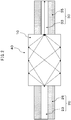
- Fig. 2 is a schematic diagram showing an example of an optical fiber device that may be used in the method of the disclosure.
- the optical fiber device shown in Fig. 2 has a sensor unit 10 composed of a multimode fiber, and an incoming light fiber 20 and outgoing light fiber 30 composed of single-mode fibers, which are optically connected to the incoming light end and outgoing light end of the sensor unit 10, respectively.
- the incoming light fiber 20 has a core 23 and a cladding 25.
- the outgoing light fiber 30 also has a core 33 and a cladding 35.
- Liquid gasoline 40 is present on the outer side of the sensor unit 10.
- the diameter of the sensor unit 10 is larger than the diameters of the cores of the incoming light fiber 20 and outgoing light fiber 30.
- incident light to the sensor unit 10 from the incoming light fiber 20 is diffracted in multiple directions, undergoing total reflection at the side walls of the sensor unit 10.
- Phase shifting by Goos-Hänchen shifting during total reflection depends on the refractive index of the sensor unit 10 and the refractive index of the gasoline on the outer side of the sensor unit.
- the optical fiber device shown in Fig. 2 it is possible to calculate the refractive index of liquid gasoline 40 by measuring the wavelength of light at which the phase just matches at the core 33 of the outgoing light fiber 30, as a value related to the refractive index.
- step A1' the proportion of the aromatic component concentration with respect to the sulfur component concentration in gasoline is lowered by removing a portion of the gasoline by gasification.
- Step A1' may be the same as step A1 described above.
- step A2' the sensor unit interior is irradiated with a laser from the incoming light fiber side, the wavelength of the irradiated laser is measured at the outgoing light fiber side, and a value related to the refractive index is measured based on the measured wavelength.
- Measurement of the value related to the refractive index in step A2' can be carried out by referring to the measuring method with the optical fiber device described in PTL 1, except that the target of measurement is the liquid gasoline used in step A1'.
- the laser irradiated into the sensor unit from the incoming light fiber side during measurement of the value related to the refractive index in step A2' may employ a laser of any desired wavelength that allows estimation of the sulfur component concentration in gasoline. More specifically, a laser with a wavelength in the range of 1500 nm to 1700 nm may be used.
- the method for recovering an exhaust gas purifying catalyst of the disclosure is a method of recovering an exhaust gas purifying catalyst that purifies exhaust gas emitted by an internal combustion engine in which gasoline is combusted, wherein the method comprises the following steps (A) to (C):
- the exhaust gas purifying catalyst that may be used to carry out the method of recovering an exhaust gas purifying catalyst according to the disclosure may be any exhaust gas purifying catalyst that can produce catalyst poisoning by sulfur oxides such as SOx in exhaust gas.
- Such an exhaust gas purifying catalyst may be, but is not limited to, a NO X storage catalyst or three-way catalyst, for example.
- Step A can be carried out by the method of estimating the concentration of sulfur components in gasoline according to the present disclosure.
- step B the estimated accumulated amount of sulfur oxides in exhaust gas emitted by an internal combustion engine is estimated based on the sulfur component concentration.
- the estimated accumulated amount of sulfur oxides in exhaust gas emitted by the internal combustion engine can be estimated, for example, from the relationship between the sulfur component concentration in gasoline estimated in step A, and the amount of gasoline combusted by the internal combustion engine. More specifically, the product of the sulfur component concentration in gasoline and the gasoline combusted by the internal combustion engine may be used as the estimated accumulated amount of sulfur oxides.
- step A when a threshold value is used for estimation of the sulfur component concentration in gasoline and it is estimated that the sulfur component concentration in gasoline is above or within the threshold value, it may estimated whether the estimated accumulated amount is above or within a value corresponding to the threshold value for the sulfur component concentration in gasoline.
- step C if the estimated accumulated amount of discharged sulfur oxides is above the threshold value, then treatment is carried out to recover the exhaust gas purifying catalyst from the sulfur oxide-derived poisons.
- the relationship between the amount of SO X discharged from an internal combustion engine and catalyst poisoning of the exhaust gas purifying catalyst due to SO X is thought to differ depending on the type, structure and manner of usage of the exhaust gas purifying catalyst. Therefore, the reduction in exhaust gas purification efficiency of the exhaust gas purifying catalyst with respect to the estimated accumulated amount of sulfur oxides may be measured first, and the threshold value established as the estimated accumulated amount of sulfur oxides at the point where the exhaust gas purification efficiency has fallen below a level appropriately established by a person skilled in the art.
- the "poisoning" of the exhaust gas purifying catalyst by sulfur oxides is reduction in the exhaust gas purification efficiency of the exhaust gas purifying catalyst by adhesion or absorption of the sulfur oxides in the exhaust gas purifying catalyst.
- Treatment for recovery of the exhaust gas purifying catalyst from poisoning by sulfur oxides in step C may be carried out by any desired treatment method that allows sulfur oxides adhering to or stored in the exhaust gas purifying catalyst to be removed from the exhaust gas purifying catalyst.
- the treatment method may be carried out, for example, by heating the exhaust gas purifying catalyst to high temperature while using a high air/fuel ratio of the exhaust gas flowing into the exhaust purification catalyst.
- Gasoline samples with benzothiophene concentrations of 1 ppm, 10 ppm, 100 ppm, 1000 ppm and 10,000 ppm were prepared to estimate sulfur concentrations in gasoline.
- the gasoline sample volatilization rate was changed as shown in Table 1 to measure the change in output of the optical fiber device at the different volatilization rates.
- the optical fiber device used for measurement had the same construction as the optical fiber device described in detail for the estimating method of the disclosure.
- the optical fiber device therefore had a sensor unit composed of a multimode fiber, running through the gasoline sample, and an incoming light fiber and outgoing light fiber composed of single-mode fibers, which were optically connected to the incoming light end and outgoing light end of the sensor unit, respectively.
- the optical fiber device had the same material for the sensor unit and the cores of the incoming light fiber and outgoing light fiber, and the diameter of the sensor unit was larger than the diameters of the cores of the incoming light fiber and outgoing light fiber.
- Light of wavelength 1520 nm to 1620 nm was supplied to the optical fiber device from an ASE light source, and the optical fiber device output was measured using an optical spectrum analyzer.
- the optical fiber device was situated on a temperature adjustment plate and the temperature of the gasoline sample was kept at 25°C during the measurement.
- Figs. 3 to 5 show the measurement results of gasoline samples using an optical fiber device, for Comparative Example 1, Example 1 and Example 2.
- the abscissa represents benzothiophene concentration in the gasoline sample
- the ordinate represents wavelength shift. The wavelength shift is based on the measurement results for a gasoline sample with a benzothiophene concentration of 1 ppm.
- Example 2 Even with a gasoline sample volatilization rate of 20 mass%, as in Example 2, the change in wavelength shift due to benzothiophene concentration was also considerable, as shown in Fig. 5 , similar to Example 1.
- Samples were prepared for Reference Examples 1 to 8 with the compositional ratios listed in Table 2, and the refractive index of each sample was measured.
- a multiple regression formula was derived by the following procedure, based on the measurement results of the proportion of each component and the refractive index, for each of the samples of the reference examples.
- the amount (cc) in each sample is represented as x 1 for benzothiophene, x 2 for toluene and x 3 for hexene.
- n A ⁇ x 1 + B ⁇ x 2 + C ⁇ x 3 + D
Landscapes
- Chemical & Material Sciences (AREA)
- Life Sciences & Earth Sciences (AREA)
- Health & Medical Sciences (AREA)
- Physics & Mathematics (AREA)
- Immunology (AREA)
- Pathology (AREA)
- Analytical Chemistry (AREA)
- Biochemistry (AREA)
- General Health & Medical Sciences (AREA)
- General Physics & Mathematics (AREA)
- Engineering & Computer Science (AREA)
- Chemical Kinetics & Catalysis (AREA)
- Medicinal Chemistry (AREA)
- Food Science & Technology (AREA)
- General Chemical & Material Sciences (AREA)
- Oil, Petroleum & Natural Gas (AREA)
- Materials Engineering (AREA)
- Organic Chemistry (AREA)
- Spectroscopy & Molecular Physics (AREA)
- Optics & Photonics (AREA)
- Investigating Or Analysing Materials By Optical Means (AREA)
- Exhaust Gas After Treatment (AREA)
- Exhaust Gas Treatment By Means Of Catalyst (AREA)
Abstract
Description
- The present disclosure relates to a method for estimating the concentration of sulfur components in gasoline.
- Methods for measuring a variety of liquid and gaseous components are known in the prior art. Examples of such methods include chromatographic methods and infrared spectroscopy. Other methods are known that use optical fiber sensors to measure the refractive indexes of liquids or gases, allowing target substances to be estimated.
-
PTL 1 discloses a method for sensing gases in gasoline, the method employing an optical fiber device using optical fibers as the gas sensor. - The optical fiber device described in
PTL 1 is an optical fiber device comprising a sensor unit in the form of an optical fiber composed of a waveguide, and an optical fiber A and optical fiber B composed of a core and cladding, which are each optically connected to one or the other end of the sensor unit and situated on one side and the other side of the sensor unit, wherein the waveguide of the sensor unit is made of the same material as the core of the optical fiber A and optical fiber B, the dimension of the sensor unit in the radial direction is larger than the dimension of the core of the optical fiber A and the dimension of the core of the optical fiber B, and the sensor unit has at least one outer surface that is completely covered with an adsorbent. According to this same publication, the components in a target substance can be detected based on the amount of Goos-Hänchen shift during total reflection at the boundary between the optical fiber and the adsorbent that is to adsorb the target substance, which is disposed on the outer peripheral side of the optical fiber sensor. - [PTL 1] Japanese Unexamined Patent Publication No.
2017-20946 - Exhaust gas produced by combustion of fuel such as gasoline in an internal combustion engine such as an automobile gasoline engine contains components such as carbon monoxide (CO), hydrocarbons (HC), and nitrogen oxides (NOX). Vehicles with internal combustion engines are therefore usually provided with exhaust gas purification catalyst apparatuses for purification of such components, whereby the components are essentially decomposed by the exhaust gas purifying catalysts mounted in the exhaust gas purification catalyst apparatuses.
- Since gasoline contains sulfur components such as benzothiophene, exhaust gas produced by combustion of gasoline also contains sulfur oxides such as SOX in addition to the components mentioned above. Such sulfur oxides adhere onto or stored by the exhaust gas purifying catalyst, thus lowering the exhaust gas purification performance of the exhaust gas purifying catalyst, i.e. causing catalyst poisoning.
- The present inventors have studied a recovery procedure in which the accumulated amount of sulfur oxides discharged from an internal combustion engine is estimated based on the sulfur component concentration in gasoline, and the sulfur oxide is removed from the exhaust gas purifying catalyst when the estimated amount exceeds a constant value.
- The present inventors also studied a method of estimating the concentration of sulfur components in gasoline wherein an optical fiber device such as disclosed in
PTL 1 is used to measure the refractive index of the gasoline in order to estimate the sulfur component concentration in the gasoline. - However, the present inventors have found that the refractive index of gasoline is greatly affected not only by the sulfur component concentration in gasoline but also by the concentration of aromatic components, and that the concentration of sulfur components and aromatic components in the gasoline differs significantly depending on the period in which the gasoline is acquired, such that it is difficult to estimate the sulfur component concentration in gasoline to high precision simply by measuring the refractive index of the gasoline.
- It is therefore an object of this disclosure to provide a method that allows the sulfur component concentration in gasoline to be estimated to high precision.
- The present inventors have found that this object can be achieved by the following means.
- <
Aspect 1> A method for estimating the concentration of sulfur components in gasoline that contains sulfur components and aromatic components, wherein the method comprises:- (A1) removing a portion of the gasoline by gasification to lower the proportion of the aromatic component concentration with respect to the sulfur component concentration in the gasoline,
- (A2) measuring values related to the refractive index of the gasoline, and
- (A3) estimating the sulfur component concentration in the gasoline based on the values related to the refractive index.
- <
Aspect 2> The method according toaspect 1, wherein in step (A2), an optical fiber device which:- has a sensor unit composed of a multimode fiber that runs through the gasoline, and
- has an incoming light fiber and outgoing light fiber composed of single-mode fibers, that are optically connected to the incoming light end and outgoing light end of the sensor unit, respectively, wherein
- the sensor unit and the cores of the incoming light fiber and outgoing light fiber are made of the same material, and
- the diameter of the sensor unit is larger than the diameters of the cores of the incoming light fiber and outgoing light fiber,
is used to irradiate the sensor unit with a laser from the incoming light fiber side and to measure the wavelength of the irradiated laser from the outgoing light fiber side, measuring the values related to the refractive index based on the measured wavelength.
- <
Aspect 3> The method according toaspect - <Aspect 4> The method according to
aspect 2, wherein in step (A1), the sensor unit interior is irradiated with a laser from the incoming light fiber side to heat the gasoline and gasify a portion of the gasoline. - <Aspect 5> The method according to any one of
aspects 1 to 4, wherein the sulfur components comprise dimethylthiophene, dibenzothiophene, benzothiophene or any combination of the same. - <Aspect 6> The method according to any one of
aspects 1 to 5, wherein the aromatic components comprise toluene. - <Aspect 7> A method for recovering an exhaust gas purifying catalyst that purifies exhaust gas emitted by an internal combustion engine in which gasoline is combusted, wherein the method comprises:
- (A) estimating the sulfur component concentration in the gasoline by the method according to any one of
aspects 1 to 6, - (B) estimating the estimated accumulated amount of sulfur oxides in the exhaust gas emitted by the internal combustion engine, based on the sulfur component concentration, and
- (C) recovering the exhaust gas purifying catalyst from the sulfur oxide-derived poisons when the estimated accumulated amount of discharged sulfur oxides is above a threshold value.
- (A) estimating the sulfur component concentration in the gasoline by the method according to any one of
- According to the disclosure it is possible to provide a method that allows the sulfur component concentration in gasoline to be estimated to high precision.
-
-
Fig. 1 is a graph illustrating the relationship between gasoline gasification rate (vol%) and the main component, sulfur component and aromatic component concentrations (vol%) in gasoline. -
Fig. 2 is a schematic diagram showing an example of an optical fiber device that may be used in the method of the disclosure. -
Fig. 3 is a graph showing the measurement results using an optical fiber device for different gasoline samples in Comparative Example 1. -
Fig. 4 is a graph showing the measurement results using an optical fiber device for different gasoline samples in Example 1. -
Fig. 5 is a graph showing the measurement results using an optical fiber device for different gasoline samples in Example 2. - Embodiments of the disclosure will now be explained in detail. The disclosure is not limited to the embodiments described below, however, and various modifications may be implemented within the scope of the gist thereof.
- The estimating method of the disclosure is a method for estimating the concentration of sulfur components in gasoline that contains sulfur components and aromatic components. The estimating method of the disclosure comprises the following steps (A1) to (A3):
- (A1) removing a portion of the gasoline by gasification to lower the proportion of the aromatic component concentration with respect to the sulfur component concentration in the gasoline,
- (A2) measuring values related to the refractive index of the gasoline, and
- (A3) estimating the sulfur component concentration in the gasoline based on the values related to the refractive index.
- Without being limited to any particular principle, it is believed that the principle by which the sulfur component concentration in gasoline can be estimated to high precision by the method of the disclosure is as follows.
- Presumably, the refractive index of gasoline is greatly affected not only by the sulfur component concentration in gasoline but also by the aromatic component concentration in gasoline.
- The saturated vapor pressure of toluene, which is the major aromatic component in gasoline, is 2.93 kPa at 20°C, while the saturated vapor pressure of benzothiophene, which is the main sulfur component in gasoline, is very low, being 1.33 Pa at 20°C. When gasoline is gasified, therefore, the aromatic components are more easily gasified than the sulfur components in the gasoline. For the alkane components as the main components of gasoline, the saturated vapor pressure of octane, for example, is 1.33 kPa at 20°C, and therefore when the method of the disclosure is applied for gasoline, the aromatic components and alkane components gasify more readily than the sulfur components in the gasoline.
- This will be explained in detail in regard to gasoline. As shown in
Fig. 1 , gasification of gasoline causes gasification of the aromatic components, thereby lowering the aromatic component content of the gasoline. The sulfur components, on the other hand, have very low saturated vapor pressure compared to the other components and undergo almost no gasification, such that the sulfur component content in the gasoline is virtually unchanged. - When the gasoline is gasified, therefore, the aromatic component concentration in the gasoline is lowered and the aromatic components contribute less to the refractive index of the gasoline, whereas the sulfur component concentration in gasoline increases, resulting in greater contribution of the sulfur components to the refractive index of the gasoline.
- Thus, if the values related to the refractive index of the gasoline are measured after lowering the proportion of the aromatic component concentration with respect to the sulfur component concentration in gasoline by gasification of a portion of the gasoline, it is possible to improve estimation precision for the sulfur component concentration in gasoline.
- The estimating method of the disclosure is carried out with gasoline containing sulfur components and aromatic components.
- The sulfur components in gasoline are compounds that contain sulfur atoms, examples of which include dimethylthiophene, dibenzothiophene, benzothiophene, and combinations of the same, although with no particular limitation to these.
- The aromatic components in gasoline include toluene, for example, but may also include other aromatic compounds.
- The gasoline to be used in the estimating method of the disclosure is a liquid. Because of the high saturated vapor pressure of sulfur components, the sulfur component concentration in gasoline vapor is expected to differ considerably from the sulfur component concentration in liquid gasoline. Therefore, the estimation precision for the sulfur component concentration in gasoline may be lower when the values related to the refractive index of gasoline vapor are measured. The estimating method of the disclosure is carried out for liquid gasoline and is therefore less susceptible to this issue.
- In step A1, the proportion of the aromatic component concentration with respect to the sulfur component concentration in gasoline is lowered by removing a portion of the gasoline by gasification.
- The gasoline used in step A1 may be gasified to between 1.0 vol% and 25.0 vol%. The gasoline may also be gasified to 1.0 vol% or more, 2.0 vol% or more, 5.0 vol% or more, or 8.0 vol% or more, and 25.0 vol% or less, 20.0 vol% or less, 15.0 vol% or less, or 10.0 vol% or less. Since a greater degree of gasoline gasification allows more of the aromatic components in the liquid gasoline to be gasified, it can increase the estimation precision for the sulfur component concentration. However, a greater degree of gasification of gasoline results in consumption of more gasoline for estimation of the sulfur component concentration in the gasoline, thus leading to greater energy loss.
- The method of gasifying a portion of the gasoline may be any desired method capable of gasifying gasoline, and for example, it may be gasification of the gasoline by allowing it to stand at ordinary temperature, or gasification by heating.
- In step A2 the values related to the refractive index of gasoline are measured.
- The values related to the refractive index, referred to here, include the value of the refractive index itself, but may also include the basic values used to calculate the refractive index. For example, the wavelength shift may be measured when using an apparatus of the specific type used in the estimating method described below.
- Step A2 may employ any method that allows the values related to the refractive index of liquid gasoline to be measured. For the values related to the refractive index, examples of methods for measuring the refractive index itself include, but are not limited to, the minimum deviation method, the Abbe or Pulfrich critical angle method, or the V-block method. Step A2 may also be carried out using an apparatus of the specific type used in the estimating method described below.
- Measurement of the values related to the refractive index for liquid gasoline is preferably carried out at a temperature for low gasification of liquid gasoline, but it may also be carried out at ordinary temperature or at above ordinary temperature. The temperature of the liquid gasoline during measurement of the values related to the refractive index for liquid gasoline may be 0°C to 50°C. The temperature of the liquid gasoline during measurement of the values related to the refractive index for liquid gasoline may also be 0°C or more, 10°C or more, or 20°C or more, and 50°C or less, 40°C or less or 30°C or less.
- In step A3, the sulfur component concentration in gasoline is estimated based on the values related to the refractive index.
- Estimation of the sulfur component concentration in gasoline may be estimation using specific numerical values in units of vol%, mass% or mol%, or it may be estimation using the magnitude relationship against a threshold value based on these same units.
- The sulfur component concentration in gasoline can be calculated using a mathematical expression representing the relationship between refractive index and sulfur component concentration according to formula (3) in the reference example, using an aromatic component concentration of 0 vol% in the gasoline (assuming a constant aromatic component concentration, i.e. assuming the aromatic components to be essentially gasified), and substituting in the measured refractive index.
- The sulfur component concentration in gasoline may be estimated by establishing threshold values for the values related to the refractive index, and determining whether or not the values are above the threshold values and also within the threshold values, to estimate whether the concentration is above the predetermined concentration or within the predetermined concentration. In this case, the threshold values may be theoretical values or measured values for the values related to the refractive index of the gasoline, at the predetermined sulfur component concentration. For example, the measured values can be determined by carrying out step A1 and step A2 for gasoline having a known sulfur component concentration.
- In the estimating method of the disclosure, steps A1 and A2 may be carried out by the following step A1' and step A2', respectively, using the following apparatus as an example.
- An example of a measuring apparatus that can be used in the estimating method of the disclosure is an optical fiber device that has a sensor unit composed of a multimode fiber that runs through the gasoline, and has an incoming light fiber and outgoing light fiber composed of single-mode fibers, that are optically connected to the incoming light end and outgoing light end of the sensor unit, respectively, wherein the sensor unit and the cores of the incoming light fiber and outgoing light fiber are made of the same material, and the diameter of the sensor unit is larger than the diameters of the cores of the incoming light fiber and outgoing light fiber.
- The optical fiber device may also be the optical fiber device described in
PTL 1, for example. - The sensor unit is composed of a multimode fiber. A multimode fiber is an optical fiber that allows light propagating through an optical fiber to propagate separately in multiple modes. The multimode fiber in the sensor unit does not have a cladding.
- The material of the sensor unit may be any desired material that can be used as a core material for an optical fiber, or it may be composed of the same material as the cores of the incoming light fiber and outgoing light fiber. In this case there will be no difference in refractive index between the incoming light fiber and the sensor unit, and between the sensor unit and the outgoing light fiber, so that light passing through the optical fiber device will be trapped inside the core without leaking at the boundary between the incoming light fiber and sensor unit or at the boundary between the sensor unit and outgoing light fiber.
- The diameter of the sensor unit is larger than the diameters of the cores of the incoming light fiber and outgoing light fiber. Strong diffraction is thus generated in the light directed from the incoming light fiber onto the sensor unit, and diffracted light produced in the sensor unit is focused by interference at the core of the outgoing light fiber, resulting in highly efficient light propagation from the sensor unit to the outgoing light fiber.
- The sensor unit passes through the gasoline, or in other words, the sensor unit is in direct contact with the liquid gasoline. During total reflection at the sensor unit, variation in the phase of the light, known as Goos-Hänchen shifting, takes place in the diffracted light passing through the sensor unit, and therefore light propagating through the center section of the sensor unit undergoes phase variation by the degree of repetition of total reflection, reaching the fiber unit at the output end. Since the phase variation in light due to Goos-Hänchen shifting depends on the refractive index of the sensor unit and the refractive index of the gasoline surrounding the sensor unit, the refractive index of the gasoline can be calculated by measuring the wavelength of light at which the phase just matches at the core of the outgoing light fiber, as a value related to the refractive index.
- The incoming light fiber is composed of a single-mode fiber, and it is optically connected to the incoming light end of the sensor unit. The outgoing light fiber is likewise composed of a single-mode fiber, and it is optically connected to the outgoing light end of the sensor unit.
- A single-mode fiber is an optical fiber allowing light propagating through an optical fiber to propagate in a single mode.
-
Fig. 2 is a schematic diagram showing an example of an optical fiber device that may be used in the method of the disclosure. The optical fiber device shown inFig. 2 has asensor unit 10 composed of a multimode fiber, and an incominglight fiber 20 and outgoinglight fiber 30 composed of single-mode fibers, which are optically connected to the incoming light end and outgoing light end of thesensor unit 10, respectively. The incominglight fiber 20 has acore 23 and acladding 25. The outgoinglight fiber 30 also has acore 33 and acladding 35.Liquid gasoline 40 is present on the outer side of thesensor unit 10. The diameter of thesensor unit 10 is larger than the diameters of the cores of the incominglight fiber 20 and outgoinglight fiber 30. - In the optical fiber device shown in
Fig. 2 , incident light to thesensor unit 10 from the incominglight fiber 20 is diffracted in multiple directions, undergoing total reflection at the side walls of thesensor unit 10. Phase shifting by Goos-Hänchen shifting during total reflection depends on the refractive index of thesensor unit 10 and the refractive index of the gasoline on the outer side of the sensor unit. By using the optical fiber device shown inFig. 2 it is possible to calculate the refractive index ofliquid gasoline 40 by measuring the wavelength of light at which the phase just matches at thecore 33 of the outgoinglight fiber 30, as a value related to the refractive index. - In step A1', the proportion of the aromatic component concentration with respect to the sulfur component concentration in gasoline is lowered by removing a portion of the gasoline by gasification. Step A1' may be the same as step A1 described above.
- In step A2', the sensor unit interior is irradiated with a laser from the incoming light fiber side, the wavelength of the irradiated laser is measured at the outgoing light fiber side, and a value related to the refractive index is measured based on the measured wavelength.
- Measurement of the value related to the refractive index in step A2' can be carried out by referring to the measuring method with the optical fiber device described in
PTL 1, except that the target of measurement is the liquid gasoline used in step A1'. - The laser irradiated into the sensor unit from the incoming light fiber side during measurement of the value related to the refractive index in step A2' may employ a laser of any desired wavelength that allows estimation of the sulfur component concentration in gasoline. More specifically, a laser with a wavelength in the range of 1500 nm to 1700 nm may be used.
- The method for recovering an exhaust gas purifying catalyst of the disclosure is a method of recovering an exhaust gas purifying catalyst that purifies exhaust gas emitted by an internal combustion engine in which gasoline is combusted, wherein the method comprises the following steps (A) to (C):
- (A) estimating the sulfur component concentration in gasoline in the manner according to the disclosure,
- (B) estimating the estimated accumulated amount of sulfur oxides in the exhaust gas emitted by the internal combustion engine, based on the sulfur component concentration, and
- (C) recovering the exhaust gas purifying catalyst from the sulfur oxide-derived poisons when the estimated accumulated amount of discharged sulfur oxides is above a threshold value.
- The exhaust gas purifying catalyst that may be used to carry out the method of recovering an exhaust gas purifying catalyst according to the disclosure may be any exhaust gas purifying catalyst that can produce catalyst poisoning by sulfur oxides such as SOx in exhaust gas. Such an exhaust gas purifying catalyst may be, but is not limited to, a NOX storage catalyst or three-way catalyst, for example.
- Step A can be carried out by the method of estimating the concentration of sulfur components in gasoline according to the present disclosure.
- In step B, the estimated accumulated amount of sulfur oxides in exhaust gas emitted by an internal combustion engine is estimated based on the sulfur component concentration. The estimated accumulated amount of sulfur oxides in exhaust gas emitted by the internal combustion engine can be estimated, for example, from the relationship between the sulfur component concentration in gasoline estimated in step A, and the amount of gasoline combusted by the internal combustion engine. More specifically, the product of the sulfur component concentration in gasoline and the gasoline combusted by the internal combustion engine may be used as the estimated accumulated amount of sulfur oxides. In step A, when a threshold value is used for estimation of the sulfur component concentration in gasoline and it is estimated that the sulfur component concentration in gasoline is above or within the threshold value, it may estimated whether the estimated accumulated amount is above or within a value corresponding to the threshold value for the sulfur component concentration in gasoline.
- In step C, if the estimated accumulated amount of discharged sulfur oxides is above the threshold value, then treatment is carried out to recover the exhaust gas purifying catalyst from the sulfur oxide-derived poisons.
- The relationship between the amount of SOX discharged from an internal combustion engine and catalyst poisoning of the exhaust gas purifying catalyst due to SOX is thought to differ depending on the type, structure and manner of usage of the exhaust gas purifying catalyst. Therefore, the reduction in exhaust gas purification efficiency of the exhaust gas purifying catalyst with respect to the estimated accumulated amount of sulfur oxides may be measured first, and the threshold value established as the estimated accumulated amount of sulfur oxides at the point where the exhaust gas purification efficiency has fallen below a level appropriately established by a person skilled in the art.
- The "poisoning" of the exhaust gas purifying catalyst by sulfur oxides is reduction in the exhaust gas purification efficiency of the exhaust gas purifying catalyst by adhesion or absorption of the sulfur oxides in the exhaust gas purifying catalyst.
- Treatment for recovery of the exhaust gas purifying catalyst from poisoning by sulfur oxides in step C may be carried out by any desired treatment method that allows sulfur oxides adhering to or stored in the exhaust gas purifying catalyst to be removed from the exhaust gas purifying catalyst. The treatment method may be carried out, for example, by heating the exhaust gas purifying catalyst to high temperature while using a high air/fuel ratio of the exhaust gas flowing into the exhaust purification catalyst.
- Gasoline samples with benzothiophene concentrations of 1 ppm, 10 ppm, 100 ppm, 1000 ppm and 10,000 ppm were prepared to estimate sulfur concentrations in gasoline. For each of the prepared gasoline samples, the gasoline sample volatilization rate was changed as shown in Table 1 to measure the change in output of the optical fiber device at the different volatilization rates.
-
Table 1 Example Volatilization rate of gasoline sample (mass%) Comparative Example 1 0 Example 1 10 Example 2 20 - The optical fiber device used for measurement had the same construction as the optical fiber device described in detail for the estimating method of the disclosure. The optical fiber device therefore had a sensor unit composed of a multimode fiber, running through the gasoline sample, and an incoming light fiber and outgoing light fiber composed of single-mode fibers, which were optically connected to the incoming light end and outgoing light end of the sensor unit, respectively. The optical fiber device had the same material for the sensor unit and the cores of the incoming light fiber and outgoing light fiber, and the diameter of the sensor unit was larger than the diameters of the cores of the incoming light fiber and outgoing light fiber.
- Light of wavelength 1520 nm to 1620 nm was supplied to the optical fiber device from an ASE light source, and the optical fiber device output was measured using an optical spectrum analyzer.
- The optical fiber device was situated on a temperature adjustment plate and the temperature of the gasoline sample was kept at 25°C during the measurement.
- The measurement results are shown in
Figs. 3 to 5. Figs. 3 to 5 show the measurement results of gasoline samples using an optical fiber device, for Comparative Example 1, Example 1 and Example 2. InFigs. 3 to 5 , the abscissa represents benzothiophene concentration in the gasoline sample, and the ordinate represents wavelength shift. The wavelength shift is based on the measurement results for a gasoline sample with a benzothiophene concentration of 1 ppm. - When the gasoline sample volatilization rate was 0 mass%, i.e. when there was absolutely no gasification of the gasoline sample, as in Comparative Example 1, there was essentially no difference, with the sizes of the wavelength shift at benzothiophene concentrations of 10 ppm, 100 ppm, 1000 ppm and 10,000 ppm being all approximately 0.8 nm, as shown in
Fig. 3 . - In contrast, when the gasoline sample volatilization rate was 10 mass% as in Example 1, the wavelength shifts with benzothiophene concentrations of 10 ppm, 100 ppm, 1000 ppm and 10,000 ppm were about 0.8 nm, 1.2 nm, 1.6 nm and 2.4 nm, in that order, as shown in
Fig. 4 , and therefore the change in wavelength shift due to the benzothiophene concentration was considerable. - Even with a gasoline sample volatilization rate of 20 mass%, as in Example 2, the change in wavelength shift due to benzothiophene concentration was also considerable, as shown in
Fig. 5 , similar to Example 1. - This result suggests that when a gasoline sample has been volatilized, volatilization of the aromatic components that are major contributors to the refractive index of the gasoline sample reduces the concentration of aromatic components in the gasoline sample, thereby increasing the contribution by the benzothiophene content for the refractive index of the gasoline sample.
- Samples were prepared for Reference Examples 1 to 8 with the compositional ratios listed in Table 2, and the refractive index of each sample was measured.
-
Table 2 Sample composition (cc) Refractive index Example Benzothiophene Toluene Hexene Hexane Reference Example 1 0.5 0.0 0.0 99.5 1.3661 Reference Example 2 0.5 0.0 40.0 59.5 1.4098 Reference Example 3 0.5 40.0 0.0 59.5 1.3707 Reference Example 4 0.5 40.0 40.0 19.5 1.4165 Reference Example 5 5.0 0.0 0.0 95.0 1.3714 Reference Example 6 5.0 0.0 40.0 55.0 1.4153 Reference Example 7 5.0 40.0 0.0 55.0 1.3764 Reference Example 8 5.0 40.0 40.0 15.0 1.4212 - A multiple regression formula was derived by the following procedure, based on the measurement results of the proportion of each component and the refractive index, for each of the samples of the reference examples. In formula (1), the amount (cc) in each sample is represented as x1 for benzothiophene, x2 for toluene and x3 for hexene.

- Defining the difference between the predicted value n and the measured value N for the refractive index as the residual error (e), the residual sum of squares Se is represented by the following formula (2).
[Mathematical Formula 1]
- The coefficients A, B, C and D were set so that Se = 0, and the relationship between the gasoline refractive index and the aromatic component concentration (vol%) and sulfur component concentration (vol%) was determined, as represented by the following formula (3). In formula (3), (a) is the aromatic component concentration (vol%) and (b) is the sulfur component concentration (vol%).

- As shown by formula (3), both the aromatic components and sulfur components contribute significantly to the refractive index of gasoline.
-
- 10
- Sensor unit
- 20
- Incoming light fiber
- 23
- Core
- 25
- Cladding
- 30
- Outgoing light fiber
- 33
- Core
- 35
- Cladding
- 40
- Liquid gasoline
Claims (7)
- A method for estimating the concentration of sulfur components in gasoline that contains sulfur components and aromatic components, wherein the method comprises:(A1) removing a portion of the gasoline by gasification to lower the proportion of the aromatic component concentration with respect to the sulfur component concentration in the gasoline,(A2) measuring values related to the refractive index of the gasoline, and(A3) estimating the sulfur component concentration in the gasoline based on the values related to the refractive index.
- The method according to claim 1, wherein in step (A2), an optical fiber device which:has a sensor unit composed of a multimode fiber that runs through the gasoline, andhas an incoming light fiber and outgoing light fiber composed of single-mode fibers, that are optically connected to the incoming light end and outgoing light end of the sensor unit, respectively, whereinthe sensor unit and the cores of the incoming light fiber and outgoing light fiber are made of the same material, andthe diameter of the sensor unit is larger than the diameters of the cores of the incoming light fiber and outgoing light fiber,
is used to irradiate the sensor unit with a laser from the incoming light fiber side and to measure the wavelength of the irradiated laser from the outgoing light fiber side, measuring the values related to the refractive index based on the measured wavelength. - The method according to claim 1 or 2, wherein in step (A1), the gasoline is heated to gasify a portion of the gasoline.
- The method according to claim 2, wherein in step (A1), the sensor unit interior is irradiated with a laser from the incoming light fiber side to heat the gasoline and gasify a portion of the gasoline.
- The method according to any one of claims 1 to 4, wherein the sulfur components comprise dimethylthiophene, dibenzothiophene, benzothiophene or any combination of the same.
- The method according to any one of claims 1 to 5, wherein the aromatic components comprise toluene.
- A method for recovering an exhaust gas purifying catalyst that purifies exhaust gas emitted by an internal combustion engine in which gasoline is combusted, wherein the method comprises:(A) estimating the sulfur component concentration in the gasoline by the method according to any one of claims 1 to 6,(B) estimating the estimated accumulated amount of sulfur oxides in the exhaust gas emitted by the internal combustion engine, based on the sulfur component concentration, and(C) recovering the exhaust gas purifying catalyst from the sulfur oxide-derived poisons when the estimated accumulated amount of discharged sulfur oxides is above a threshold value.
Applications Claiming Priority (1)
| Application Number | Priority Date | Filing Date | Title |
|---|---|---|---|
| JP2019210427A JP7144388B2 (en) | 2019-11-21 | 2019-11-21 | Method for estimating the concentration of sulfur components in gasoline |
Publications (1)
| Publication Number | Publication Date |
|---|---|
| EP3825679A1 true EP3825679A1 (en) | 2021-05-26 |
Family
ID=73343862
Family Applications (1)
| Application Number | Title | Priority Date | Filing Date |
|---|---|---|---|
| EP20206853.2A Withdrawn EP3825679A1 (en) | 2019-11-21 | 2020-11-11 | Method for estimating sulfur component concentration in gasoline |
Country Status (7)
| Country | Link |
|---|---|
| US (1) | US11933725B2 (en) |
| EP (1) | EP3825679A1 (en) |
| JP (1) | JP7144388B2 (en) |
| KR (1) | KR20210062582A (en) |
| CN (1) | CN112824876A (en) |
| BR (1) | BR102020023658A2 (en) |
| RU (1) | RU2756504C1 (en) |
Citations (4)
| Publication number | Priority date | Publication date | Assignee | Title |
|---|---|---|---|---|
| JPS6291840A (en) * | 1985-10-18 | 1987-04-27 | Hitachi Ltd | Fuel property detector |
| JP2001303937A (en) * | 2000-02-18 | 2001-10-31 | Toyota Motor Corp | Exhaust gas purification device for internal combustion engine |
| CN102507497A (en) * | 2011-10-27 | 2012-06-20 | 中国科学技术大学 | Refractive index sensor based on optical fiber and measurement method |
| JP2017020946A (en) | 2015-07-13 | 2017-01-26 | 国立大学法人 岡山大学 | Optical fiber device |
Family Cites Families (26)
| Publication number | Priority date | Publication date | Assignee | Title |
|---|---|---|---|---|
| JPH0645254Y2 (en) * | 1985-07-02 | 1994-11-16 | 日本油脂株式会社 | Device for removing volatile components from analytical samples |
| CA2239548A1 (en) * | 1995-12-05 | 1997-06-12 | Hoechst Industry Limited | Optical fuel vapor detector utilizing thin polymer film and fuel leak monitor system |
| US6140647A (en) * | 1997-12-19 | 2000-10-31 | Marathon Ashland Petroleum | Gasoline RFG analysis by a spectrometer |
| JP2001050893A (en) | 1999-08-05 | 2001-02-23 | Nok Corp | Method and device for measuring characteristics of gasoline |
| DE19963932A1 (en) * | 1999-12-31 | 2001-07-12 | Bosch Gmbh Robert | Method for operating an internal combustion engine, in particular a motor vehicle |
| CN100437093C (en) * | 2000-06-23 | 2008-11-26 | 梁传信 | Optical-fiber chemical sensor and its detection method and device |
| RU2163717C1 (en) * | 2000-06-26 | 2001-02-27 | Николаев Вячеслав Федорович | Method determining total content of aromatic hydrocarbons in oil fractions and light oil products |
| US6849239B2 (en) * | 2000-10-16 | 2005-02-01 | E. I. Du Pont De Nemours And Company | Method and apparatus for analyzing mixtures of gases |
| US6683681B2 (en) * | 2002-04-10 | 2004-01-27 | Baker Hughes Incorporated | Method and apparatus for a downhole refractometer and attenuated reflectance spectrometer |
| JP4103456B2 (en) * | 2002-05-27 | 2008-06-18 | 日産自動車株式会社 | Exhaust gas purification device for internal combustion engine |
| US20050069455A1 (en) * | 2003-09-30 | 2005-03-31 | Rosemount Analytical Inc. | Chemical analyzer for sulfur |
| JP2006348091A (en) | 2005-06-14 | 2006-12-28 | National Institute Of Advanced Industrial & Technology | Method for separating and concentrating sulfur-containing compounds in light fuel oil |
| KR100748740B1 (en) * | 2005-11-23 | 2007-08-13 | 현대자동차주식회사 | Test method for poisoning by sulfur component in fuel |
| US7428838B2 (en) * | 2006-08-31 | 2008-09-30 | Caterpillar Inc. | Calibration for an oil-consumption-measurement system |
| JP5012036B2 (en) * | 2007-01-17 | 2012-08-29 | トヨタ自動車株式会社 | Sulfur component detector |
| US7520163B2 (en) * | 2007-06-22 | 2009-04-21 | Spx Corporation | Sulfur in fuel tester |
| JP4840274B2 (en) * | 2007-07-11 | 2011-12-21 | トヨタ自動車株式会社 | Method for detecting sulfur concentration in fuel and oil |
| JP2010101801A (en) * | 2008-10-24 | 2010-05-06 | Mitsubishi Electric Corp | Fuel property detection device |
| US8638111B2 (en) * | 2010-06-17 | 2014-01-28 | Caterpillar Inc. | Zinc oxide sulfur sensor measurement system |
| JP5791073B2 (en) | 2011-06-07 | 2015-10-07 | 国立大学法人 岡山大学 | Refractive index detection method and optical fiber sensor system |
| EP2540663B1 (en) * | 2011-06-30 | 2019-07-31 | Neste Oyj | Method for adjusting hydrogen to carbon monoxide ratio in synthesis gas |
| US20150033709A1 (en) * | 2013-07-31 | 2015-02-05 | General Electric Company | Sulfur sensor for engine exhaust |
| JP6391305B2 (en) | 2014-06-10 | 2018-09-19 | 学校法人 創価大学 | Optical fiber sensor device |
| JP6468784B2 (en) * | 2014-10-07 | 2019-02-13 | 愛三工業株式会社 | Fuel property sensor |
| JP6413047B1 (en) | 2016-12-16 | 2018-10-24 | 株式会社トクヤマ | Analytical method for adhesion resin of crushed polysilicon |
| KR102552023B1 (en) * | 2018-08-28 | 2023-07-05 | 현대자동차 주식회사 | Method of analyzing fuel component using an rf sensor for a vehicle |
-
2019
- 2019-11-21 JP JP2019210427A patent/JP7144388B2/en active Active
-
2020
- 2020-11-09 US US17/092,437 patent/US11933725B2/en active Active
- 2020-11-11 EP EP20206853.2A patent/EP3825679A1/en not_active Withdrawn
- 2020-11-13 CN CN202011267895.7A patent/CN112824876A/en active Pending
- 2020-11-16 RU RU2020137427A patent/RU2756504C1/en active
- 2020-11-19 BR BR102020023658-0A patent/BR102020023658A2/en not_active IP Right Cessation
- 2020-11-20 KR KR1020200156812A patent/KR20210062582A/en not_active Abandoned
Patent Citations (4)
| Publication number | Priority date | Publication date | Assignee | Title |
|---|---|---|---|---|
| JPS6291840A (en) * | 1985-10-18 | 1987-04-27 | Hitachi Ltd | Fuel property detector |
| JP2001303937A (en) * | 2000-02-18 | 2001-10-31 | Toyota Motor Corp | Exhaust gas purification device for internal combustion engine |
| CN102507497A (en) * | 2011-10-27 | 2012-06-20 | 中国科学技术大学 | Refractive index sensor based on optical fiber and measurement method |
| JP2017020946A (en) | 2015-07-13 | 2017-01-26 | 国立大学法人 岡山大学 | Optical fiber device |
Also Published As
| Publication number | Publication date |
|---|---|
| JP7144388B2 (en) | 2022-09-29 |
| CN112824876A (en) | 2021-05-21 |
| KR20210062582A (en) | 2021-05-31 |
| JP2021081356A (en) | 2021-05-27 |
| BR102020023658A2 (en) | 2021-08-10 |
| US20210156797A1 (en) | 2021-05-27 |
| RU2756504C1 (en) | 2021-10-01 |
| US11933725B2 (en) | 2024-03-19 |
Similar Documents
| Publication | Publication Date | Title |
|---|---|---|
| Khalek et al. | Particle emissions from a 2009 gasoline direct injection engine using different commercially available fuels | |
| US7672544B2 (en) | Optical fiber sensor | |
| JP5583970B2 (en) | A method for ensuring the safety of components of a vehicle drive train following the deterioration of fuel | |
| RU2471172C2 (en) | Apparatus for centralised control of measurements and data associated with flow of liquid and gas, necessary for operation of internal combustion engine | |
| CN101413877A (en) | System and method for sensing fuel moisturization | |
| JP2007163422A (en) | Exhaust gas analysis method and exhaust gas analyzer | |
| Sappok et al. | Radio frequency diesel particulate filter soot and ash level sensors: Enabling adaptive controls for heavy-duty diesel applications | |
| EP3146176A1 (en) | Method for diagnosing the efficiency of a three-way catalytic converter | |
| Haisch et al. | Photoacoustic analyzer for the artifact-free parallel detection of soot and NO2 in engine exhaust | |
| US11933725B2 (en) | Method for estimating sulfur component concentration in gasoline | |
| Moses-DeBusk et al. | Nonuniform oxidation behavior of loaded gasoline particulate filters | |
| KR20210121234A (en) | How to determine the concentration of gaseous species in biogas | |
| Kondo et al. | Development Of On-board Multi-component Gas Analyzer Toward Euro 7 | |
| Pisano et al. | A UV differential optical absorption spectrometer for the measurement of sulfur dioxide emissions from vehicles | |
| JP6866987B2 (en) | Optical fiber equipment | |
| Dooly et al. | Optical sensing of hazardous exhaust emissions using a UV based extrinsic sensor | |
| FR2746851A1 (en) | METHOD AND DEVICE FOR CLOSED LOOP REGULATION OF THE RICHNESS OF AN AIR / FUEL MIXTURE INTENDED TO SUPPLY AN INTERNAL COMBUSTION ENGINE | |
| JPH07103895A (en) | Exhaust component concentration detector | |
| Lacquet et al. | Long-period grating with sol-gel coating for CO2 detection | |
| Li et al. | Tuneable diode laser spectroscopy correction factor investigation on ammonia measurement | |
| Pisano et al. | Laboratory Testing of a Continuous Emissions Monitor for Trace Level Sulfur Dioxide | |
| Hill et al. | Time-Resolved Measurement of Vehicle Sulfate and Methane Emissions With Tunable Diode Lasers | |
| Durbin et al. | Impact of engine lubricant properties on regulated gaseous emissions of 2000-2001 model-year gasoline vehicles | |
| Nakamura et al. | Development of a new UVF Analyzer with O3 injection for Measurement of SOx and TRS in Vehicle Emission | |
| Merola et al. | Optical Investigation of Post-injection Strategy Impact on the Fuel Vapor within the Exhaust Line of a Light Duty Diesel Engine Supplied with Biodiesel Blends |
Legal Events
| Date | Code | Title | Description |
|---|---|---|---|
| PUAI | Public reference made under article 153(3) epc to a published international application that has entered the european phase |
Free format text: ORIGINAL CODE: 0009012 |
|
| STAA | Information on the status of an ep patent application or granted ep patent |
Free format text: STATUS: REQUEST FOR EXAMINATION WAS MADE |
|
| 17P | Request for examination filed |
Effective date: 20201111 |
|
| AK | Designated contracting states |
Kind code of ref document: A1 Designated state(s): AL AT BE BG CH CY CZ DE DK EE ES FI FR GB GR HR HU IE IS IT LI LT LU LV MC MK MT NL NO PL PT RO RS SE SI SK SM TR |
|
| GRAP | Despatch of communication of intention to grant a patent |
Free format text: ORIGINAL CODE: EPIDOSNIGR1 |
|
| STAA | Information on the status of an ep patent application or granted ep patent |
Free format text: STATUS: GRANT OF PATENT IS INTENDED |
|
| RIC1 | Information provided on ipc code assigned before grant |
Ipc: G01N 21/43 20060101ALN20220429BHEP Ipc: G01N 33/28 20060101ALI20220429BHEP Ipc: G01N 21/41 20060101AFI20220429BHEP |
|
| INTG | Intention to grant announced |
Effective date: 20220516 |
|
| STAA | Information on the status of an ep patent application or granted ep patent |
Free format text: STATUS: THE APPLICATION IS DEEMED TO BE WITHDRAWN |
|
| 18D | Application deemed to be withdrawn |
Effective date: 20220927 |