EP3825635A1 - A reinforcement for a heat exchanger - Google Patents
A reinforcement for a heat exchanger Download PDFInfo
- Publication number
- EP3825635A1 EP3825635A1 EP19461605.8A EP19461605A EP3825635A1 EP 3825635 A1 EP3825635 A1 EP 3825635A1 EP 19461605 A EP19461605 A EP 19461605A EP 3825635 A1 EP3825635 A1 EP 3825635A1
- Authority
- EP
- European Patent Office
- Prior art keywords
- tube
- reinforcement
- heat exchanger
- section
- tubes
- Prior art date
- Legal status (The legal status is an assumption and is not a legal conclusion. Google has not performed a legal analysis and makes no representation as to the accuracy of the status listed.)
- Withdrawn
Links
- 230000002787 reinforcement Effects 0.000 title claims abstract description 156
- 238000004873 anchoring Methods 0.000 claims description 7
- 239000002826 coolant Substances 0.000 description 9
- 229910052751 metal Inorganic materials 0.000 description 8
- 239000002184 metal Substances 0.000 description 8
- 238000000034 method Methods 0.000 description 8
- 239000000463 material Substances 0.000 description 6
- 239000012530 fluid Substances 0.000 description 4
- 238000004519 manufacturing process Methods 0.000 description 4
- 238000003780 insertion Methods 0.000 description 3
- 230000037431 insertion Effects 0.000 description 3
- 238000012546 transfer Methods 0.000 description 3
- 229910052782 aluminium Inorganic materials 0.000 description 2
- XAGFODPZIPBFFR-UHFFFAOYSA-N aluminium Chemical compound [Al] XAGFODPZIPBFFR-UHFFFAOYSA-N 0.000 description 2
- 238000005219 brazing Methods 0.000 description 2
- 238000004891 communication Methods 0.000 description 2
- 230000003247 decreasing effect Effects 0.000 description 2
- 230000000694 effects Effects 0.000 description 2
- 230000035939 shock Effects 0.000 description 2
- 229920002994 synthetic fiber Polymers 0.000 description 2
- 238000004378 air conditioning Methods 0.000 description 1
- 238000005452 bending Methods 0.000 description 1
- 230000009286 beneficial effect Effects 0.000 description 1
- 230000000903 blocking effect Effects 0.000 description 1
- 238000002485 combustion reaction Methods 0.000 description 1
- 230000007797 corrosion Effects 0.000 description 1
- 238000005260 corrosion Methods 0.000 description 1
- 238000002788 crimping Methods 0.000 description 1
- 230000006378 damage Effects 0.000 description 1
- 230000001419 dependent effect Effects 0.000 description 1
- 239000006185 dispersion Substances 0.000 description 1
- 238000009826 distribution Methods 0.000 description 1
- 238000005265 energy consumption Methods 0.000 description 1
- 238000001125 extrusion Methods 0.000 description 1
- 239000000446 fuel Substances 0.000 description 1
- 230000003100 immobilizing effect Effects 0.000 description 1
- 230000007257 malfunction Effects 0.000 description 1
- 229910001092 metal group alloy Inorganic materials 0.000 description 1
- 239000007769 metal material Substances 0.000 description 1
- 230000000149 penetrating effect Effects 0.000 description 1
- 230000003014 reinforcing effect Effects 0.000 description 1
- 238000005549 size reduction Methods 0.000 description 1
- 230000003685 thermal hair damage Effects 0.000 description 1
- XLYOFNOQVPJJNP-UHFFFAOYSA-N water Substances O XLYOFNOQVPJJNP-UHFFFAOYSA-N 0.000 description 1
- 238000003466 welding Methods 0.000 description 1
Images



Classifications
-
- F—MECHANICAL ENGINEERING; LIGHTING; HEATING; WEAPONS; BLASTING
- F28—HEAT EXCHANGE IN GENERAL
- F28D—HEAT-EXCHANGE APPARATUS, NOT PROVIDED FOR IN ANOTHER SUBCLASS, IN WHICH THE HEAT-EXCHANGE MEDIA DO NOT COME INTO DIRECT CONTACT
- F28D1/00—Heat-exchange apparatus having stationary conduit assemblies for one heat-exchange medium only, the media being in contact with different sides of the conduit wall, in which the other heat-exchange medium is a large body of fluid, e.g. domestic or motor car radiators
- F28D1/02—Heat-exchange apparatus having stationary conduit assemblies for one heat-exchange medium only, the media being in contact with different sides of the conduit wall, in which the other heat-exchange medium is a large body of fluid, e.g. domestic or motor car radiators with heat-exchange conduits immersed in the body of fluid
- F28D1/04—Heat-exchange apparatus having stationary conduit assemblies for one heat-exchange medium only, the media being in contact with different sides of the conduit wall, in which the other heat-exchange medium is a large body of fluid, e.g. domestic or motor car radiators with heat-exchange conduits immersed in the body of fluid with tubular conduits
- F28D1/053—Heat-exchange apparatus having stationary conduit assemblies for one heat-exchange medium only, the media being in contact with different sides of the conduit wall, in which the other heat-exchange medium is a large body of fluid, e.g. domestic or motor car radiators with heat-exchange conduits immersed in the body of fluid with tubular conduits the conduits being straight
- F28D1/0535—Heat-exchange apparatus having stationary conduit assemblies for one heat-exchange medium only, the media being in contact with different sides of the conduit wall, in which the other heat-exchange medium is a large body of fluid, e.g. domestic or motor car radiators with heat-exchange conduits immersed in the body of fluid with tubular conduits the conduits being straight the conduits having a non-circular cross-section
- F28D1/05366—Assemblies of conduits connected to common headers, e.g. core type radiators
-
- F—MECHANICAL ENGINEERING; LIGHTING; HEATING; WEAPONS; BLASTING
- F28—HEAT EXCHANGE IN GENERAL
- F28F—DETAILS OF HEAT-EXCHANGE AND HEAT-TRANSFER APPARATUS, OF GENERAL APPLICATION
- F28F9/00—Casings; Header boxes; Auxiliary supports for elements; Auxiliary members within casings
- F28F9/001—Casings in the form of plate-like arrangements; Frames enclosing a heat exchange core
- F28F9/002—Casings in the form of plate-like arrangements; Frames enclosing a heat exchange core with fastening means for other structures
-
- F—MECHANICAL ENGINEERING; LIGHTING; HEATING; WEAPONS; BLASTING
- F28—HEAT EXCHANGE IN GENERAL
- F28F—DETAILS OF HEAT-EXCHANGE AND HEAT-TRANSFER APPARATUS, OF GENERAL APPLICATION
- F28F2225/00—Reinforcing means
- F28F2225/08—Reinforcing means for header boxes
Definitions
- the invention relates to a heat exchanger, in particular to the heat exchanger for a motor vehicle.
- Heat exchangers in motor vehicles are usually responsible for thermal management of the powertrain, the air conditioning system, the power steering system, and other. This includes, for example, internal combustion vehicles and electric vehicles, wherein the proper management of the heat can reflect on emissions, fuel or energy consumption, maximal driving range, etc.
- the similar effects may be obtained, for example, by reducing the weight and the size of the vehicle components, such as the heat exchanger.
- the size of the heat exchanger may be reduced by implementing specific architectures that provide the same or better efficiency while using the smaller amount of space.
- the weight of the sub-components may decrease, as well as the size thereof.
- the weight can be further decreased by reducing the amount of material used for sub- components production, for example, by slimming the walls of the particular components.
- the heat exchangers these days are usually made of a metal components, such as aluminum assembled with a synthetic components, such as plastic.
- the sub-components responsible for heat exchange, such as the heat exchanger core comprising tubes assembled with the headers are usually made of metal component, whereas the sub-components responsible for delivering or collecting the media, such as tanks, are usually made synthetic material.
- the heat exchanger core expands and/or contracts depending on the temperature of media and pressure accumulated in the system.
- the thermal expansion of the material can make the tubes want to move with respect to the header, thus increasing a threat of leakage.
- the heat exchanger may suffer so-called thermal shock every time the hot medium is directed into the core and said core expansion occurs it the short time.
- the core contracts and returns to its nominal size, which can be regarded as dimensions of the heat exchanger in the standard temperature and under normal pressure.
- the cycles of operational and non-operational mode may a significantly impact the longevity of the heat exchanger due to both thermal, mechanical load and corrosion.
- the common area mostly vulnerable to thermal damage and leakage is located usually in the vicinity of the middle portion of the tube, in particular where the tube enters the manifold.
- the support means are configured to strengthen the inner walls of the tube by the legs extending from the terminal end of the tube and finishing beyond the point where the tube goes through the slot.
- already existing designs include, for example, a fork-shaped portion entered using force into the terminal end of the tube. The process of introducing such portions requires a lot of precision and force from e.g. the operator.
- Another negative aspect is the amount of time required to reinforce the tubes of a single heat exchanger, as only one portion at a time may be introduced into the tube.
- Other applications provide reinforcement of two consecutive tubes by using a single supporting means, however, it still may not be sufficient.
- the object of the invention is, among others, a heat exchanger, in particular for a motor vehicle comprising: a first header, a first tank assembled with the first header, a second header, a second tank assembled with the second header, a plurality of tubes deployed in parallel to each other between the first header and the second header, the tubes comprising open ends received in the headers, and at least one tube reinforcement, characterised in that, the tube reinforcement comprises a support element and at least two central reinforcement sections protruding substantially perpendicularly from the support element, wherein the central reinforcement sections are in bonded contact with respective central portions of the inner walls of at least two tubes.
- the invention provides a tube reinforcement for two or more tubes.
- the tube reinforcement may be produced in a cheap and efficient way. Providing a reinforcement that supports the middle portion of the tubes improves the heat exchanger's efficiency and prevents malfunction, due to e.g. thermal shock.
- the tube reinforcement comprises at least one side reinforcement section, wherein the side reinforcement section is in a contact with respective lateral portions of the inner walls of at least two tubes, so that they reinforce a lateral portions thereof.
- the tube comprises an inner wall deployed between the two opposite walls of the tube, wherein at least one central reinforcement section in a contact with the inner wall.
- the tube reinforcement comprises at least one opening section deployed on the support element, the opening section comprising at least one opening configured to fluidly communicate the tank with the tube adjacent to said opening, wherein the opening comprises two shorter sides parallel to the shorter walls of the tube, and two longer sides parallel to the longer walls of the tube.
- the central reinforcement section protrudes from the shorter side of the opening deployed substantially in the center of the support section, and the side reinforcement section protrudes from the shorter side of the opening deployed substantially on the side of the support section.
- the opening section is of a size substantially equal to the inner perimeter of the open end of the tube.
- the opening section comprises at least two openings which are aligned in series and parallelly to the open end of the adjacent tube.
- the openings adjacent to the same tube are inclined with respect to the tube and shifted with respect to each other in the direction of the consecutive tubes.
- the tube reinforcement comprises at least one intermediate opening deployed between the open ends of consecutive tubes.
- the tube comprises an inner wall deployed between the two opposite walls of the tube, wherein at least one central reinforcement section in a contact with the inner wall.
- the central reinforcement section is in a form of an essentially unitary plate protruding perpendicularly from the support element.
- the unitary plate comprises also the side reinforcement section.
- the central reinforcement section is in a form of a legs protruding perpendicularly from the support element.
- the legs forming a central reinforcement section are deployed in two substantially parallel rows, each row being deployed on one side of the inner wall.
- the central reinforcement section comprises a carving configured to receive the terminal end of the inner wall, so that the tube reinforcement is immobilized in a direction perpendicular to the axial direction with respect to the tubes.
- the length of the projecting legs protruding from the opening section is substantially equal to the half of length of a longer side of the opening.
- the length of the projecting legs protruding from the opening section is substantially equal to the length of the longer side of the opening.
- the width of the projecting legs is substantially equal to half of the shorter side of the opening section.
- the tube reinforcement comprises at least one bar extending perpendicularly to the central reinforcement section the bar being configured to immobilize with respect to each other at least two support portions.
- the bar is integral with at least one of the surfaces of the support portions.
- the bar is integral with the upper surfaces of the support portions.
- the bar is integral with the lower surfaces of the support portions.
- the bar is integral with the side surfaces of the neighboring support portions.
- bar is integral with the terminal surfaces of the neighboring support portions.
- the heat exchanger comprises at least one unreinforced tube deployed between the subsequently projecting legs of the tube reinforcement.
- the central reinforcement section and/or the side reinforcement section comprise beveled ends.
- the tube reinforcement is made of the single sheet of metal.
- the invention relates to heat exchangers, in particular radiators used in automobiles.
- Fig.1 presents a heat exchanger 1, in particular a radiator that may be used in an automobile.
- the heat exchanger 1 is configured to convey a cooling medium, such as a coolant through its sub-components so that the temperature of the cooling medium flowing out of the heat exchanger 1 would be lower than the temperature of the cooling medium flowing into the heat exchanger 1 thanks to heat exchange with a second medium, e.g. air.
- a cooling medium such as a coolant
- the cooling medium is usually delivered into the heat exchanger 1 by an inlet and collected from by an outlet.
- the inlet and the outlet are usually deployed either on the opposite sides of the heat exchanger 1, or on the same side of the heat exchanger 1.
- the inlet and the outlet have usually circular cross-section protruding from inlet and/or outlet of the tanks 40, 50, respectively.
- the first tank 40 is usually an elongated container made of synthetic material that is configured to distribute the cooling medium, whereas the second tank 50 is configured to collect the cooling medium from the heat exchanger 1. Alternatively, a reversed flow through the heat exchanger 1 is allowed.
- Both tanks 40, 50 usually comprise an openings having substantially rectangular cross-section for receiving a header 2, 3 with a tubes 4.
- the shape of the tanks 40, 50 presented in the Fig.1 is proven to ensure a homogenous distribution of coolant, yet other shapes of the tanks 40, 50 that will provide similar or better performance are also allowed.
- the tanks 40, 50 may also comprise a plurality of transverse ribs deployed alternately in a direction perpendicular to the longitudinal direction of the tanks 40, 50. Ribs provide rigidity of the tanks 40, 50 at high pressures and ensure reduced deformations thereof.
- the tanks 40, 50 widen at the side of the rectangular opening to enable tight connection with a respective headers 2, 3.
- the headers 2, 3 are usually an elongated plates made of metal material.
- the metallic components of the heat exchanger 1 are made of light-weight metal alloy e.g. aluminum.
- the headers 2, 3 usually have a shape similar to the shape of the openings comprised in the tanks 40, 50. In most applications, the synthetic tanks 40,50 are assembled with metal headers 2, 3 by the means of crimping one to the other, as welding is impossible.
- the headers 2, 3 usually comprise slots for receiving a plurality of tubes 4 which protrude from the flat surface of the header 2, 3 towards the tanks 40, 50.
- the number of slots is usually equal to the number of the tubes 4.
- the tubes 4 are usually made of a single sheet of metal which is folded inwardly, so that the terminal ends of metal sheet create an inner wall 5 that can be attached (e.g. by brazing) to the flat portion of the tube 4.
- the inner wall 5 is deployed between the two opposite walls of the tube 4.
- the tubes 4 are made in the process of extrusion. It is also possible for the tubes 4 to not comprise any inner walls 5 e.g. the tubes may be folded on its side.
- the tubes 4 comprise two open ends, and they are usually deployed in parallel to each other between the first header 2 and the second header 3, wherein the open ends of the tubes 4 are received in the slots of the headers 2, 3. To provide a tight connection, the headers 2, 3 and the tubes 4 may be brazed together.
- the heat exchanger 1 comprises also at least one tube reinforcement 10, which can be made of a single sheet of metal.
- the tube reinforcements 10 may be entered between the tubes 4 and the tank 40, 50, as presented in the Figures 1 and 2 .
- Fig. 1 presents only an exemplary location of the tube reinforcement 10 in the heat exchanger 1.
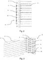
- Fig.2 presents an assembly of the header 2, 3 comprising a plurality of the tubes 4 and the tube reinforcement 10.
- the space between the tubes 4 may be filled by heat dispersion elements (not shown), for example fins, in order to increase the heat exchanger 1 efficiency.
- the tube reinforcement 10 comprises in all of its forms a support element 11, which is essentially a flat portion perpendicular to the main direction of the tubes 4.
- the support element 11 neither enters the slot of the header 2, 3, nor the open ends of the tubes 4 and it is usually deployed between the header 2, 3 and the tank 40, 50.
- the support element 11 visible in Fig. 2 and Fig. 3 is made of a single sheet of metal and it comprises two lateral walls perpendicular to the main direction of the tubes 4 and parallel to the main direction of the header 2, 3, and two transverse walls which are essentially perpendicular to the lateral walls.
- Phrase "essentially perpendicular" means that some leftover material forming a sloping wall comprised in the lateral wall is allowed. In majority of applications, the lateral walls are longer than the transverse walls, yet the support element 11 comprising the transverse walls longer or equal to the lateral walls is also envisaged.
- the tube reinforcement 10 comprises also a central reinforcement section 12 located substantially perpendicularly with respect to the support element 11.
- the central reinforcement sections 12 are formed from the support element 11, so that both portions are materially connected. This may be achieved, for example, by using the stamping process, wherein it may be executable to cut the material to form the central reinforcement sections 12 in the first action, and to bend them to desired orientation with respect to the support element 11 in the second action. Alternatively, it may be feasible to laser cut the material to shape the projecting legs 12 in the first action, and to bend them to desired orientation in with respect to the support element 11 in the second action. Alternatively, it may be feasible to water jet the material to shape the projecting legs 12 in the first action, and to bend them to desired orientation in with respect to the support element 11 in the second action.
- the central reinforcement section may be attached to the support portion using intermediate component.
- the central reinforcement sections 12 are usually introduced into at least two consecutive tubes 4.
- the central reinforcement sections 12 enter the tubes 4 so that they at least partially penetrate the cross- section of the header 2, 3, for example as presented in the Fig. 2 .
- the central reinforcement sections 12 are deployed in the tubes 4, so that they remain in a contact with the inner walls of the tube 4, and at least one side of the inner wall 5 if the tube 4 comprises it.
- the central reinforcement sections 12 may comprise a beveled ends to facilitate introducing the central reinforcement sections 12 into the tubes 4.
- the features described in this paragraph may also refer to deployment and manufacturing process of a side reinforcement sections 13.
- the side reinforcement sections 13 are usually located at the sides of the tubes 4, in particular in the vicinity of their shorter walls.
- Fig. 3 presents an exploded view of the exemplary tube reinforcement 10 pre-inserted into the open ends of the tubes 4.
- the tube reinforcement 10 comprises at least one opening section 30.
- the opening section 30 has an essentially rectangular shape, wherein the longer sides are substantially parallel to the transverse walls of the support portion 11.
- the opening section 30 is of a size substantially equal to the inner perimeter of the open end of the tube 4.
- the outline of the opening section 30 corresponds to the inner perimeter of the open end of the tube 4.
- the opening section 30 enables fluidal communication between the tube 4 and the tanks 40, 50 by at least one opening 6, 7 comprised therein.
- the openings 6, 7 may be aligned in series and parallelly to the open end of the adjacent tube 4.
- the openings 6, 7 adjacent to the same tube 4 may be inclined with respect to the tube 4 and shifted with respect to each other substantially in the direction of the consecutive tubes 4, as presented in the Fig. 3 . This allows to improve rigidity of the plate compared to non-shifted arrangement by limiting the length of relatively thin wall portions between the openings 6, 7.
- Using shifted openings 6, 7 in some applications may be beneficial in terms of e.g. pressure drop.
- the number of the openings 6, 7 in the single opening section 30 may be increased by at least one in reference to the number of the inner walls 5 comprised within the single tube 4.
- the openings 6, 7 are configured to fluidly communicate the tanks 40, 50 with the tube 4, in particular the tube 4 which is in the nearest vicinity of the opening 6, 7.
- the central reinforcement section 12 may protrude from the opening 6, 7.
- the central reinforcement section 12 usually protrudes from the shorter side of the opening 6, 7 deployed substantially in the center of the support section 11.
- the side reinforcement section 13 usually protrudes from the shorter side of the opening 6, 7 deployed substantially on the side of the support section 11.
- the central reinforcement section 12 can form two rows of legs.
- the rows formed substantially in the center of support section are usually introduced in the middle portion of the tube, so that the inner wall 5 could be reinforced by them, whereas the rows formed substantially at the sides of the support portion 11 are usually introduced in the side portion of the tube, so that the side portion of the tube 4 may be reinforced by them.
- This enables to create a reinforced area in the vicinity of the middle portion of the tubes 4, as well as the reinforced area on both sides of the tubes 4.
- reinforcing the sides of the tubes is optional.
- Such reinforcement may prevent the tubes 4 from thermal and mechanical stress in their most vulnerable area.
- the central reinforcement section 12 may protrude from the openings 6, 7 in at least two different ways.
- One pair of central reinforcement section 12 carried out from the openings 6, 7 may be separated along the axis of symmetry of the opening 6, 7 being perpendicular to its longer side. In other words, the central reinforcement section may be cut and bent in the middle of the opening.
- the length of the central reinforcement section 12 protruding from the opening section 30 may be substantially equal to the half of length of a longer side of the opening 6, 7.
- the one row of central reinforcement section 12 carried out from the opening 6, 7 may also be separated along the axis of symmetry of the opening 6, 7 being parallel to its longer side, so that the projecting legs are deployed alternately with respect to each other, as shown in the Fig. 3 .
- the length of the central reinforcement section 12 protruding from the opening section 30 is substantially equal to the length of the longer side of the opening 6,7.
- the method of deployment of the alternate legs on the central reinforcement section 12 and side reinforcement section 13 may be preferred for the shifted openings 6, 7 deployment, so that the projecting legs comprised in one opening section 30 would be aligned linearly with respect to the open ends of the tube 4.
- both methods of deploying the central reinforcement section 12 and the side reinforcement section 13 in a form of the projecting legs may be advantageous in certain circumstances.
- the protruding legs are shorter than in the second example, but they are thicker and less vulnerable for deformations, as the width of the projecting legs is substantially equal to shorter side of the opening section 30.
- the projecting legs are longer than in the first example, but they are able to penetrate deeper into the tube 4 to increase the contact area between the projecting legs and the inner side of the tube 4, as the width of the projecting legs is substantially equal to half of the shorter side of the opening section 30.
- one pair of projecting legs carried out from the opening 6, 7 may be separated along the diagonal axis of the opening 6, 7 forming spiky- shaped legs, however, this form of legs would be undesired due to complicated production process.
- the legs forming the central reinforcement section 12 protruding from the support element 11 may comprise a length, a width, and a thickness, wherein the width of the single leg is usually greater than its thickness and the length is greater than width and thickness.
- the thicker projecting legs significantly limit unwanted bending thereof and also increase contact surface between the tube reinforcement 10 and the inner wall of the tube 4.
- the subject of an invention may be produced also in a different way as shown in Figs 4-8 .
- Figs. 4-6 show the tube reinforcements 10 comprising, amongst others, the support elements 11, the central reinforcement sections 12 protruding from the support element 11, and at least one side reinforcement section 13.
- the support elements 11 may comprise at least one through hole which facilitates the insertion process of the tube reinforcement 10 into the tubes 4.
- the tube reinforcements 10 comprise two through holes deployed symmetrically and penetrating the support elements 11 towards the header 2, 3.
- the tube reinforcement 10 may comprise at least one intermediate opening 8 deployed between the open ends of consecutive tubes 4, as shown in Fig. 8 .
- the intermediate opening 8 has an essentially rectangular shape and it facilitates the fluid transfer between the tubes 4 and in the vicinity of the headers 2, 3. Further, the intermediate openings 8 also facilitates the insertion process of the tube reinforcement 10 into the tubes.
- the support portions 11 may comprise an arched portion connecting the central reinforcement sections 12 and/or side reinforcement sections 13 with the side surfaces of the support portions 11. It further allows an undisturbed fluid transfer between the tube 4 and the tanks 40, 50 by preventing the support element 11 from blocking the ends of the tube 4. In other words, the arched portion are deployed symmetrically between the two adjacent tubes 4 so that the fluidal communication between the tubes 4 and the tanks 40, 50 is enabled.
- Fig. 4 presents the tube reinforcement 10 in a form of a single element comprising the support portion 11 and the central reinforcement section 12.
- the support element 11 comprises a flat portion extending along the direction substantially perpendicular to the axial direction of the tube 4.
- the tube reinforcement 11 comprises two through holes for facilitating the insertion of the tube reinforcement 10 into the tube 4.
- the central reinforcement section 12 may be in a form of an essentially unitary plate protruding essentially perpendicularly with respect to the support element 11.
- the central reinforcement section 12 is configured to support the middle portion of two neighboring tubes 4.
- the tube reinforcement 10 may also comprise at least one side reinforcement section 13 deployed on both sides thereof and arranged in the same manner as the central reinforcement section 12, i.e. the central reinforcement section 12 and the side reinforcement section 13 may form a continuous unitary plate as shown in Fig. 4 .
- the tube reinforcement 10 having this particular shape is suitable both for extruded and for folded tubes 4, providing that the inner wall 5 of aforementioned folded tube 4 allows the central reinforcement section 13 to be slid into the tube 4.
- Fig. 5 presents the tube reinforcement 10 comprising the support element 11, at least one side reinforcement section 13, and the central reinforcement section 12.
- the support element 11 comprises two arched portions connecting the side reinforcement sections 13 with the side surfaces of the support portions 11 as shown in Fig. 5 .
- the central reinforcement section 12 protrudes o from a pair of side reinforcement portions 13 which in this particular embodiment play a role of linking elements.
- Other methods of assembling the central reinforcement sections 12 using linking elements in also envisaged. This configuration is feasible for increased coolant fluid flow in the heat exchanger 1.
- Fig. 6 presents the tube reinforcement 10 comprising the support element 11, at least one side reinforcement section 13, and the central reinforcement section 12.
- the support element 11 may comprise several arched portions connecting the side reinforcement sections 13 and central reinforcement sections 12, both protruding perpendicularly from the longer sides of the support portion 11, wherein the side reinforcement section 13 is L-shaped and it is materially connected with the inverted U-shaped central reinforcement sections 12 as shown in Fig. 6 .
- the tube reinforcement 10 further comprises a carving 15 configured to receive the terminal end of the inner wall 5, so that the tube reinforcement 10 is immobilized in a direction perpendicular to the axial direction with respect to the tube 4.
- the carving 15 is in a form of a groove in the middle of the center reinforcement section 12 caving towards the arched portion and the support section 11, however, other means of immobilizing the tube reinforcement 10 with respect to the tube 4 in a direction perpendicular to the axial direction with respect to the tube 4 is also envisaged.
- the carving 15 may be deployed elsewhere, depending on the location of the inner wall 5.
- Fig. 7 shows the tube reinforcement 10 comprising the support element 11, at least one side reinforcement section 13, and the central reinforcement section 12.
- the tube reinforcement 10 comprises also an anchoring notches 16 protruding between the support portion 11 and the central reinforcement section 12.
- the anchoring notches 16 may enable shifting the support portion 11 towards the header 2,3 along the axial direction of the tubes 4.
- the anchoring notches 16 are presented as an inverted U-shape portions deployed between the reinforcement sections 12, 13 and the support portion 11, however, other shapes of the anchoring notches are also envisaged.
- Fig. 8 shows the tube reinforcement 10 comprising the support element 11, at least one side reinforcement section 13, the central reinforcement section 12, and the anchoring notches 16.
- the tube reinforcement 10 comprises also at least one intermediate opening 8 deployed between the open ends of consecutive tubes 4.
- the tube reinforcement 10 may also comprise several segments immobilized with respect to each other by the means of the bar (not shown) extending perpendicularly to the support portion 11.
- the bar may be deployed symmetrically between the consecutive support portions 11 by the means of e.g. brazing.
- the bar may be integral with the consecutive support portions 11.
- integral means that there is a consolidated connection between at least two elements, so that distinguishing these elements or the means of connecting them is impossible.
- the integrated bar may connect the sides of one support element 11 with the side of the consecutive support element 11.
- the integrated bars may be deployed symmetrically with respect to each other.
- the first bar may connect one sides of the consecutive support portions 11 and the second bar may connect other sides of the consecutive of the support portions 11.
- the heat exchanger 1 may also comprise at least one unreinforced tube (not shown) deployed between the subsequent tube reinforcements 10.
- unreinforced refers to at least one tube 4, which is in the perimeter of the tube reinforcement 10, but the central reinforcement section 12 is of reduced length or not provided at all, so that it does not reach the inner walls of the tube 4 and does not come into contact with them.
Landscapes
- Engineering & Computer Science (AREA)
- Physics & Mathematics (AREA)
- Thermal Sciences (AREA)
- Mechanical Engineering (AREA)
- General Engineering & Computer Science (AREA)
- Heat-Exchange Devices With Radiators And Conduit Assemblies (AREA)
Abstract
Description
- The invention relates to a heat exchanger, in particular to the heat exchanger for a motor vehicle.
- Heat exchangers in motor vehicles are usually responsible for thermal management of the powertrain, the air conditioning system, the power steering system, and other. This includes, for example, internal combustion vehicles and electric vehicles, wherein the proper management of the heat can reflect on emissions, fuel or energy consumption, maximal driving range, etc. The similar effects may be obtained, for example, by reducing the weight and the size of the vehicle components, such as the heat exchanger. The size of the heat exchanger may be reduced by implementing specific architectures that provide the same or better efficiency while using the smaller amount of space. As the result, the weight of the sub-components may decrease, as well as the size thereof. Furthermore, the weight can be further decreased by reducing the amount of material used for sub- components production, for example, by slimming the walls of the particular components.
- However, the ongoing interest in continuous weight and size reduction of vehicle's sub-components may lead to its undesired vulnerability to damage and/or decreased efficiency of the whole heat exchange system. The heat exchangers these days are usually made of a metal components, such as aluminum assembled with a synthetic components, such as plastic. The sub-components responsible for heat exchange, such as the heat exchanger core comprising tubes assembled with the headers are usually made of metal component, whereas the sub-components responsible for delivering or collecting the media, such as tanks, are usually made synthetic material.
- In operational mode, the heat exchanger core expands and/or contracts depending on the temperature of media and pressure accumulated in the system. The thermal expansion of the material can make the tubes want to move with respect to the header, thus increasing a threat of leakage. Further, the heat exchanger may suffer so-called thermal shock every time the hot medium is directed into the core and said core expansion occurs it the short time. Between the subsequent operational modes the core contracts and returns to its nominal size, which can be regarded as dimensions of the heat exchanger in the standard temperature and under normal pressure.
- Thus, the cycles of operational and non-operational mode may a significantly impact the longevity of the heat exchanger due to both thermal, mechanical load and corrosion.
- The common area mostly vulnerable to thermal damage and leakage is located usually in the vicinity of the middle portion of the tube, in particular where the tube enters the manifold.
- To remedy the negative effects of upper mentioned factors one may provide a supporting means for the most vulnerable parts of the core. Usually, the support means are configured to strengthen the inner walls of the tube by the legs extending from the terminal end of the tube and finishing beyond the point where the tube goes through the slot. Already existing designs include, for example, a fork-shaped portion entered using force into the terminal end of the tube. The process of introducing such portions requires a lot of precision and force from e.g. the operator. Another negative aspect is the amount of time required to reinforce the tubes of a single heat exchanger, as only one portion at a time may be introduced into the tube. Other applications provide reinforcement of two consecutive tubes by using a single supporting means, however, it still may not be sufficient.
- It would be desired to provide a supporting means for a heat exchanger that would reinforce the middle portion of at least two tubes. Moreover, these supporting means should be cheap, efficient and easy to manufacture in large quantities.
- The object of the invention is, among others, a heat exchanger, in particular for a motor vehicle comprising: a first header, a first tank assembled with the first header, a second header, a second tank assembled with the second header, a plurality of tubes deployed in parallel to each other between the first header and the second header, the tubes comprising open ends received in the headers, and at least one tube reinforcement, characterised in that, the tube reinforcement comprises a support element and at least two central reinforcement sections protruding substantially perpendicularly from the support element, wherein the central reinforcement sections are in bonded contact with respective central portions of the inner walls of at least two tubes.
- The invention provides a tube reinforcement for two or more tubes. The tube reinforcement may be produced in a cheap and efficient way. Providing a reinforcement that supports the middle portion of the tubes improves the heat exchanger's efficiency and prevents malfunction, due to e.g. thermal shock.
- Preferably, the tube reinforcement comprises at least one side reinforcement section, wherein the side reinforcement section is in a contact with respective lateral portions of the inner walls of at least two tubes, so that they reinforce a lateral portions thereof.
- Preferably, the tube comprises an inner wall deployed between the two opposite walls of the tube, wherein at least one central reinforcement section in a contact with the inner wall.
- Preferably, the tube reinforcement comprises at least one opening section deployed on the support element, the opening section comprising at least one opening configured to fluidly communicate the tank with the tube adjacent to said opening, wherein the opening comprises two shorter sides parallel to the shorter walls of the tube, and two longer sides parallel to the longer walls of the tube.
- Preferably, the central reinforcement section protrudes from the shorter side of the opening deployed substantially in the center of the support section, and the side reinforcement section protrudes from the shorter side of the opening deployed substantially on the side of the support section.
- Preferably, the opening section is of a size substantially equal to the inner perimeter of the open end of the tube.
- Preferably, the opening section comprises at least two openings which are aligned in series and parallelly to the open end of the adjacent tube.
- Preferably, the openings adjacent to the same tube are inclined with respect to the tube and shifted with respect to each other in the direction of the consecutive tubes.
- Preferably, the tube reinforcement comprises at least one intermediate opening deployed between the open ends of consecutive tubes.
- Preferably, the tube comprises an inner wall deployed between the two opposite walls of the tube, wherein at least one central reinforcement section in a contact with the inner wall.
- Preferably, the central reinforcement section is in a form of an essentially unitary plate protruding perpendicularly from the support element.
- Preferably, the unitary plate comprises also the side reinforcement section.
- Preferably, the central reinforcement section is in a form of a legs protruding perpendicularly from the support element.
- Preferably, the legs forming a central reinforcement section are deployed in two substantially parallel rows, each row being deployed on one side of the inner wall.
- Preferably, the central reinforcement section comprises a carving configured to receive the terminal end of the inner wall, so that the tube reinforcement is immobilized in a direction perpendicular to the axial direction with respect to the tubes.
- Preferably, the length of the projecting legs protruding from the opening section is substantially equal to the half of length of a longer side of the opening.
- Preferably, the length of the projecting legs protruding from the opening section is substantially equal to the length of the longer side of the opening.
- Preferably, the width of the projecting legs is substantially equal to half of the shorter side of the opening section.
- Preferably, the tube reinforcement comprises at least one bar extending perpendicularly to the central reinforcement section the bar being configured to immobilize with respect to each other at least two support portions.
- Preferably, the bar is integral with at least one of the surfaces of the support portions.
- Preferably, the bar is integral with the upper surfaces of the support portions.
- Preferably, the bar is integral with the lower surfaces of the support portions.
- Preferably, the bar is integral with the side surfaces of the neighboring support portions.
- Preferably, bar is integral with the terminal surfaces of the neighboring support portions.
- Preferably, the heat exchanger, comprises at least one unreinforced tube deployed between the subsequently projecting legs of the tube reinforcement.
- Preferably, the central reinforcement section and/or the side reinforcement section comprise beveled ends.
- Preferably, the tube reinforcement is made of the single sheet of metal.
- Examples of the invention will be apparent from and described in detail with reference to the accompanying drawings, in which:
-
Fig. 1 shows an exploded view of a heat exchanger with tube reinforcement in one of the examples. -
Fig. 2 shows a partially transparent side view of tube reinforcement deployment in one of the examples. -
Fig. 3 shows a perspective exploded view of tube reinforcement- tube assembly in one of the examples. -
Fig. 4 shows a perspective view of the tube reinforcement in form of a unitary plate in one of the examples. -
Fig. 5 shows a perspective view of the tube reinforcement with facilitating fluid transfer in one of the examples. -
Fig. 6 shows a perspective view of the tube reinforcement with carving in one of the examples. -
Fig. 7 shows a side view of the tube reinforcement with carving in one of the examples. -
Fig. 8 shows a perspective view of the tube reinforcement with anchoring device in one of the examples. -
Fig. 9 shows a perspective view of the tube reinforcement with intermediate openings in one of the examples. - The invention relates to heat exchangers, in particular radiators used in automobiles.
-
Fig.1 presents aheat exchanger 1, in particular a radiator that may be used in an automobile. Theheat exchanger 1 is configured to convey a cooling medium, such as a coolant through its sub-components so that the temperature of the cooling medium flowing out of theheat exchanger 1 would be lower than the temperature of the cooling medium flowing into theheat exchanger 1 thanks to heat exchange with a second medium, e.g. air. - The cooling medium is usually delivered into the
heat exchanger 1 by an inlet and collected from by an outlet. Depending on the architecture, i.e. the number of passes, desired heat exchanger deployment in the engine bay, etc., the inlet and the outlet are usually deployed either on the opposite sides of theheat exchanger 1, or on the same side of theheat exchanger 1. The inlet and the outlet have usually circular cross-section protruding from inlet and/or outlet of thetanks - The
first tank 40 is usually an elongated container made of synthetic material that is configured to distribute the cooling medium, whereas thesecond tank 50 is configured to collect the cooling medium from theheat exchanger 1. Alternatively, a reversed flow through theheat exchanger 1 is allowed. Bothtanks header tubes 4. The shape of thetanks Fig.1 is proven to ensure a homogenous distribution of coolant, yet other shapes of thetanks - The
tanks tanks tanks tanks respective headers - The
headers heat exchanger 1 are made of light-weight metal alloy e.g. aluminum. Theheaders tanks synthetic tanks metal headers - The
headers tubes 4 which protrude from the flat surface of theheader tanks tubes 4. - The
tubes 4 are usually made of a single sheet of metal which is folded inwardly, so that the terminal ends of metal sheet create aninner wall 5 that can be attached (e.g. by brazing) to the flat portion of thetube 4. Theinner wall 5 is deployed between the two opposite walls of thetube 4. Alternatively, thetubes 4 are made in the process of extrusion. It is also possible for thetubes 4 to not comprise anyinner walls 5 e.g. the tubes may be folded on its side. - The
tubes 4 comprise two open ends, and they are usually deployed in parallel to each other between thefirst header 2 and thesecond header 3, wherein the open ends of thetubes 4 are received in the slots of theheaders headers tubes 4 may be brazed together. - The
heat exchanger 1 comprises also at least onetube reinforcement 10, which can be made of a single sheet of metal. Thetube reinforcements 10 may be entered between thetubes 4 and thetank Figures 1 and2 .Fig. 1 presents only an exemplary location of thetube reinforcement 10 in theheat exchanger 1. -
Fig.2 presents an assembly of theheader tubes 4 and thetube reinforcement 10. The space between thetubes 4 may be filled by heat dispersion elements (not shown), for example fins, in order to increase theheat exchanger 1 efficiency. - The
tube reinforcement 10 comprises in all of its forms asupport element 11, which is essentially a flat portion perpendicular to the main direction of thetubes 4. Thesupport element 11 neither enters the slot of theheader tubes 4 and it is usually deployed between theheader tank support element 11 visible inFig. 2 and Fig. 3 is made of a single sheet of metal and it comprises two lateral walls perpendicular to the main direction of thetubes 4 and parallel to the main direction of theheader support element 11 comprising the transverse walls longer or equal to the lateral walls is also envisaged. - The
tube reinforcement 10 comprises also acentral reinforcement section 12 located substantially perpendicularly with respect to thesupport element 11. Thecentral reinforcement sections 12 are formed from thesupport element 11, so that both portions are materially connected. This may be achieved, for example, by using the stamping process, wherein it may be executable to cut the material to form thecentral reinforcement sections 12 in the first action, and to bend them to desired orientation with respect to thesupport element 11 in the second action. Alternatively, it may be feasible to laser cut the material to shape the projectinglegs 12 in the first action, and to bend them to desired orientation in with respect to thesupport element 11 in the second action. Alternatively, it may be feasible to water jet the material to shape the projectinglegs 12 in the first action, and to bend them to desired orientation in with respect to thesupport element 11 in the second action. Alternatively, the central reinforcement section may be attached to the support portion using intermediate component. Thecentral reinforcement sections 12 are usually introduced into at least twoconsecutive tubes 4. Thecentral reinforcement sections 12 enter thetubes 4 so that they at least partially penetrate the cross- section of theheader Fig. 2 . Thecentral reinforcement sections 12 are deployed in thetubes 4, so that they remain in a contact with the inner walls of thetube 4, and at least one side of theinner wall 5 if thetube 4 comprises it. Thecentral reinforcement sections 12 may comprise a beveled ends to facilitate introducing thecentral reinforcement sections 12 into thetubes 4. The features described in this paragraph may also refer to deployment and manufacturing process of aside reinforcement sections 13. - The
side reinforcement sections 13 are usually located at the sides of thetubes 4, in particular in the vicinity of their shorter walls. -
Fig. 3 presents an exploded view of theexemplary tube reinforcement 10 pre-inserted into the open ends of thetubes 4. Thetube reinforcement 10 comprises at least oneopening section 30. Theopening section 30 has an essentially rectangular shape, wherein the longer sides are substantially parallel to the transverse walls of thesupport portion 11. Theopening section 30 is of a size substantially equal to the inner perimeter of the open end of thetube 4. In other words, the outline of theopening section 30 corresponds to the inner perimeter of the open end of thetube 4. This includes also thetube 4 comprising theinner wall 5, wherein the inner perimeter of the open end of thetube 4 would be delimited by the sum of inner perimeters of two adjacent channels, which are divided by theinner wall 5. - The
opening section 30 enables fluidal communication between thetube 4 and thetanks opening openings adjacent tube 4. Alternatively, theopenings same tube 4 may be inclined with respect to thetube 4 and shifted with respect to each other substantially in the direction of theconsecutive tubes 4, as presented in theFig. 3 . This allows to improve rigidity of the plate compared to non-shifted arrangement by limiting the length of relatively thin wall portions between theopenings openings openings single opening section 30 may be increased by at least one in reference to the number of theinner walls 5 comprised within thesingle tube 4. Theopenings tanks tube 4, in particular thetube 4 which is in the nearest vicinity of theopening - As shown in the
Fig. 3 , thecentral reinforcement section 12 may protrude from theopening central reinforcement section 12 usually protrudes from the shorter side of theopening support section 11. Theside reinforcement section 13 usually protrudes from the shorter side of theopening support section 11. Thecentral reinforcement section 12 can form two rows of legs. The rows formed substantially in the center of support section are usually introduced in the middle portion of the tube, so that theinner wall 5 could be reinforced by them, whereas the rows formed substantially at the sides of thesupport portion 11 are usually introduced in the side portion of the tube, so that the side portion of thetube 4 may be reinforced by them. This enables to create a reinforced area in the vicinity of the middle portion of thetubes 4, as well as the reinforced area on both sides of thetubes 4. However, reinforcing the sides of the tubes is optional. - Such reinforcement may prevent the
tubes 4 from thermal and mechanical stress in their most vulnerable area. - Further, the
central reinforcement section 12 may protrude from theopenings central reinforcement section 12 carried out from theopenings opening central reinforcement section 12 protruding from theopening section 30 may be substantially equal to the half of length of a longer side of theopening central reinforcement section 12 carried out from theopening opening Fig. 3 . As the consequence, the length of thecentral reinforcement section 12 protruding from theopening section 30 is substantially equal to the length of the longer side of theopening - The method of deployment of the alternate legs on the
central reinforcement section 12 andside reinforcement section 13 may be preferred for the shiftedopenings opening section 30 would be aligned linearly with respect to the open ends of thetube 4. - Both methods of deploying the
central reinforcement section 12 and theside reinforcement section 13 in a form of the projecting legs may be advantageous in certain circumstances. In the first example, the protruding legs are shorter than in the second example, but they are thicker and less vulnerable for deformations, as the width of the projecting legs is substantially equal to shorter side of theopening section 30. - In the second example, the projecting legs are longer than in the first example, but they are able to penetrate deeper into the
tube 4 to increase the contact area between the projecting legs and the inner side of thetube 4, as the width of the projecting legs is substantially equal to half of the shorter side of theopening section 30. - Alternatively, one pair of projecting legs carried out from the
opening opening central reinforcement section 12 protruding from thesupport element 11 may comprise a length, a width, and a thickness, wherein the width of the single leg is usually greater than its thickness and the length is greater than width and thickness. The thicker projecting legs significantly limit unwanted bending thereof and also increase contact surface between thetube reinforcement 10 and the inner wall of thetube 4. - The subject of an invention may be produced also in a different way as shown in
Figs 4-8 . -
Figs. 4-6 show thetube reinforcements 10 comprising, amongst others, thesupport elements 11, thecentral reinforcement sections 12 protruding from thesupport element 11, and at least oneside reinforcement section 13. - The
support elements 11 may comprise at least one through hole which facilitates the insertion process of thetube reinforcement 10 into thetubes 4. In the embodiments presented in theFigs 4-7 , thetube reinforcements 10 comprise two through holes deployed symmetrically and penetrating thesupport elements 11 towards theheader - Alternatively, the
tube reinforcement 10 may comprise at least oneintermediate opening 8 deployed between the open ends ofconsecutive tubes 4, as shown inFig. 8 . Theintermediate opening 8 has an essentially rectangular shape and it facilitates the fluid transfer between thetubes 4 and in the vicinity of theheaders intermediate openings 8 also facilitates the insertion process of thetube reinforcement 10 into the tubes. - The
support portions 11 may comprise an arched portion connecting thecentral reinforcement sections 12 and/orside reinforcement sections 13 with the side surfaces of thesupport portions 11. It further allows an undisturbed fluid transfer between thetube 4 and thetanks support element 11 from blocking the ends of thetube 4. In other words, the arched portion are deployed symmetrically between the twoadjacent tubes 4 so that the fluidal communication between thetubes 4 and thetanks -
Fig. 4 presents thetube reinforcement 10 in a form of a single element comprising thesupport portion 11 and thecentral reinforcement section 12. - The
support element 11 comprises a flat portion extending along the direction substantially perpendicular to the axial direction of thetube 4. Thetube reinforcement 11 comprises two through holes for facilitating the insertion of thetube reinforcement 10 into thetube 4. - In this particular example, the
central reinforcement section 12 may be in a form of an essentially unitary plate protruding essentially perpendicularly with respect to thesupport element 11. Thecentral reinforcement section 12 is configured to support the middle portion of two neighboringtubes 4. - The
tube reinforcement 10 may also comprise at least oneside reinforcement section 13 deployed on both sides thereof and arranged in the same manner as thecentral reinforcement section 12, i.e. thecentral reinforcement section 12 and theside reinforcement section 13 may form a continuous unitary plate as shown inFig. 4 . Thetube reinforcement 10 having this particular shape is suitable both for extruded and for foldedtubes 4, providing that theinner wall 5 of aforementioned foldedtube 4 allows thecentral reinforcement section 13 to be slid into thetube 4. -
Fig. 5 presents thetube reinforcement 10 comprising thesupport element 11, at least oneside reinforcement section 13, and thecentral reinforcement section 12. - In this particular example, the
support element 11 comprises two arched portions connecting theside reinforcement sections 13 with the side surfaces of thesupport portions 11 as shown inFig. 5 . Thecentral reinforcement section 12 protrudes o from a pair ofside reinforcement portions 13 which in this particular embodiment play a role of linking elements. Other methods of assembling thecentral reinforcement sections 12 using linking elements in also envisaged. This configuration is feasible for increased coolant fluid flow in theheat exchanger 1. -
Fig. 6 presents thetube reinforcement 10 comprising thesupport element 11, at least oneside reinforcement section 13, and thecentral reinforcement section 12. In this particular example, thesupport element 11 may comprise several arched portions connecting theside reinforcement sections 13 andcentral reinforcement sections 12, both protruding perpendicularly from the longer sides of thesupport portion 11, wherein theside reinforcement section 13 is L-shaped and it is materially connected with the inverted U-shapedcentral reinforcement sections 12 as shown inFig. 6 . Thetube reinforcement 10 further comprises a carving 15 configured to receive the terminal end of theinner wall 5, so that thetube reinforcement 10 is immobilized in a direction perpendicular to the axial direction with respect to thetube 4. In theFig. 6 the carving 15 is in a form of a groove in the middle of thecenter reinforcement section 12 caving towards the arched portion and thesupport section 11, however, other means of immobilizing thetube reinforcement 10 with respect to thetube 4 in a direction perpendicular to the axial direction with respect to thetube 4 is also envisaged. The carving 15 may be deployed elsewhere, depending on the location of theinner wall 5. -
Fig. 7 shows thetube reinforcement 10 comprising thesupport element 11, at least oneside reinforcement section 13, and thecentral reinforcement section 12. In this particular example, thetube reinforcement 10 comprises also an anchoringnotches 16 protruding between thesupport portion 11 and thecentral reinforcement section 12. The anchoringnotches 16 may enable shifting thesupport portion 11 towards theheader tubes 4. InFig. 7 , the anchoringnotches 16 are presented as an inverted U-shape portions deployed between thereinforcement sections support portion 11, however, other shapes of the anchoring notches are also envisaged. -
Fig. 8 shows thetube reinforcement 10 comprising thesupport element 11, at least oneside reinforcement section 13, thecentral reinforcement section 12, and the anchoringnotches 16. In this particular example, thetube reinforcement 10 comprises also at least oneintermediate opening 8 deployed between the open ends ofconsecutive tubes 4. - The
tube reinforcement 10 may also comprise several segments immobilized with respect to each other by the means of the bar (not shown) extending perpendicularly to thesupport portion 11. The bar may be deployed symmetrically between theconsecutive support portions 11 by the means of e.g. brazing. Alternatively, the bar may be integral with theconsecutive support portions 11. - The term "integral" means that there is a consolidated connection between at least two elements, so that distinguishing these elements or the means of connecting them is impossible.
- Several segments may also be immobilized with respect to each other by the means of the integrated bar extending perpendicularly to the
central reinforcement section 12. The integrated bar may connect the sides of onesupport element 11 with the side of theconsecutive support element 11. - Several segments may be also immobilized with respect to each other by the means of the two integrated bars (not shown) extending perpendicularly to the
central reinforcement section 12. The integrated bars may be deployed symmetrically with respect to each other. The first bar may connect one sides of theconsecutive support portions 11 and the second bar may connect other sides of the consecutive of thesupport portions 11. - The
heat exchanger 1 may also comprise at least one unreinforced tube (not shown) deployed between thesubsequent tube reinforcements 10. The term "unreinforced" refers to at least onetube 4, which is in the perimeter of thetube reinforcement 10, but thecentral reinforcement section 12 is of reduced length or not provided at all, so that it does not reach the inner walls of thetube 4 and does not come into contact with them. - Other variations to the disclosed embodiments can be understood and effected by those skilled in the art in practicing the claimed invention, from a study of drawings, the disclosure, and the appended claims. The mere fact that certain measures are recited in mutually different dependent claims does not indicate that a combination of these measures cannot be used to the advantage.
Claims (15)
- A heat exchanger (1) in particular for a motor vehicle comprising:- a first header (2),- a first tank (40) assembled with the first header (2),- a second header (3),- a second tank (50) assembled with the second header (3),- a plurality of tubes (4) deployed in parallel to each other between the first header (2) and the second header (3), the tubes (4) comprising open ends received in the headers (2,3), and- at least one tube reinforcement (10),characterised in that,
the tube reinforcement (10) comprises a support element (11) and at least two central reinforcement sections (12) protruding substantially perpendicularly from the support element (11), wherein the central reinforcement sections (12) are in bonded contact with respective central portions of the inner walls of at least two tubes (4). - The heat exchanger (1) according to claim 1, wherein the tube reinforcement (10) comprises at least one side reinforcement section (13), wherein the side reinforcement section (13) is in a contact with respective side portions of the inner walls of at least two tubes (4) so that they reinforce a side portions thereof.
- The heat exchanger (1) according to any of the preceding claims, wherein the tube reinforcement (10) comprises at least one opening section (30) deployed on the support element (11), the opening section (30) comprising at least one opening (6,7) configured to fluidly communicate the tank (40, 50) with the tube (4) adjacent to said opening (6, 7), wherein the opening (6,7) comprises two shorter sides parallel to the shorter walls of the tube (4), and two longer sides parallel to the longer walls of the tube (4).
- The heat exchanger (1) according to claim 3, wherein the central reinforcement section (12) protrudes from the shorter side of the opening (6, 7) deployed substantially in the center of the support section (11), and the side reinforcement section (13) protrudes from the shorter side of the opening (6, 7) deployed substantially on the side of the support section (11).
- The heat exchanger (1) according to any of the preceding claims, wherein the opening section (30) comprises at least two openings (6,7) which are aligned in series and parallelly to the open end of the adjacent tube (4).
- The heat exchanger (1) according to any of the preceding claims, wherein the openings (6, 7) adjacent to the same tube (4) are inclined with respect to the tube (4) and shifted with respect to each other in the direction of the consecutive tubes (4).
- The heat exchanger (1) according to any of the preceding claims, wherein the tube reinforcement (10) comprises at least one intermediate opening (8) deployed between the open ends of consecutive tubes (4).
- The heat exchanger (1) according to any of the preceding claims, wherein the tube (4) comprises an inner wall (5) deployed between the two opposite walls of the tube (4), wherein at least one central reinforcement section (12) in a contact with the inner wall (5).
- The heat exchanger (1) according to any of the preceding claims, wherein the central reinforcement section (12) is in a form of an essentially unitary plate protruding perpendicularly from the support element (11).
- The heat exchanger (1) according to claim 9, wherein the unitary plate comprises also the side reinforcement section (13).
- The heat exchanger (1) according to any of the preceding claims, wherein the central reinforcement section (12) is in a form of a legs protruding perpendicularly from the support element (11).
- The heat exchanger (1) according to claim 11, wherein the legs forming a central reinforcement section (12) are deployed in two substantially parallel rows, each row being deployed on one side of the inner wall (5).
- The heat exchanger (1) according to any of the preceding claims, wherein central reinforcement section (12) comprises a carving (15) configured to receive the terminal end of the inner wall (5), so that the tube reinforcement (10) is immobilized in a direction perpendicular to the axial direction with respect to the tube (4).
- The heat exchanger (1) according to any of the preceding claims, wherein the tube reinforcement (10) comprises an anchoring notches (16) protruding between the support portion (11) and the central reinforcement section (12), wherein the support portion (11) is shifted towards the header (2,3) along the axial direction of the tubes (4).
- The heat exchanger (1) according any of the preceding claims, wherein the tube reinforcement (10) comprises at least one bar extending perpendicularly to the central reinforcement section (12) the bar being configured to immobilize with respect to each other at least two support portions (11).
Priority Applications (2)
| Application Number | Priority Date | Filing Date | Title |
|---|---|---|---|
| EP19461605.8A EP3825635A1 (en) | 2019-11-19 | 2019-11-19 | A reinforcement for a heat exchanger |
| PCT/EP2020/082450 WO2021099339A1 (en) | 2019-11-19 | 2020-11-17 | A reinforcement for a heat exchanger |
Applications Claiming Priority (1)
| Application Number | Priority Date | Filing Date | Title |
|---|---|---|---|
| EP19461605.8A EP3825635A1 (en) | 2019-11-19 | 2019-11-19 | A reinforcement for a heat exchanger |
Publications (1)
| Publication Number | Publication Date |
|---|---|
| EP3825635A1 true EP3825635A1 (en) | 2021-05-26 |
Family
ID=68733008
Family Applications (1)
| Application Number | Title | Priority Date | Filing Date |
|---|---|---|---|
| EP19461605.8A Withdrawn EP3825635A1 (en) | 2019-11-19 | 2019-11-19 | A reinforcement for a heat exchanger |
Country Status (2)
| Country | Link |
|---|---|
| EP (1) | EP3825635A1 (en) |
| WO (1) | WO2021099339A1 (en) |
Cited By (1)
| Publication number | Priority date | Publication date | Assignee | Title |
|---|---|---|---|---|
| EP4407268A1 (en) * | 2023-01-25 | 2024-07-31 | Valeo Systemes Thermiques | A reinforcement insert |
Citations (6)
| Publication number | Priority date | Publication date | Assignee | Title |
|---|---|---|---|---|
| US20050263263A1 (en) * | 2004-06-01 | 2005-12-01 | Modine Manufacturing Company | Thermal cycling resistant tube to header joint for heat exchangers |
| US20070131404A1 (en) * | 2005-12-09 | 2007-06-14 | Denso Corporation | Heat exchanger |
| US20070144718A1 (en) * | 2003-11-20 | 2007-06-28 | Behr Gmbh & Co. Kg | Heat exchanger, especially charge air cooler for motor vehicles |
| JP2011038655A (en) * | 2009-08-07 | 2011-02-24 | T Rad Co Ltd | Reinforcement structure of heat exchanger |
| DE202014103206U1 (en) * | 2014-07-11 | 2015-10-14 | Autokühler GmbH & Co. KG | heat exchangers |
| DE102018121042A1 (en) * | 2017-09-01 | 2019-03-07 | Denso Corporation | HEAT RELIEF TENSION BRACE |
-
2019
- 2019-11-19 EP EP19461605.8A patent/EP3825635A1/en not_active Withdrawn
-
2020
- 2020-11-17 WO PCT/EP2020/082450 patent/WO2021099339A1/en not_active Ceased
Patent Citations (6)
| Publication number | Priority date | Publication date | Assignee | Title |
|---|---|---|---|---|
| US20070144718A1 (en) * | 2003-11-20 | 2007-06-28 | Behr Gmbh & Co. Kg | Heat exchanger, especially charge air cooler for motor vehicles |
| US20050263263A1 (en) * | 2004-06-01 | 2005-12-01 | Modine Manufacturing Company | Thermal cycling resistant tube to header joint for heat exchangers |
| US20070131404A1 (en) * | 2005-12-09 | 2007-06-14 | Denso Corporation | Heat exchanger |
| JP2011038655A (en) * | 2009-08-07 | 2011-02-24 | T Rad Co Ltd | Reinforcement structure of heat exchanger |
| DE202014103206U1 (en) * | 2014-07-11 | 2015-10-14 | Autokühler GmbH & Co. KG | heat exchangers |
| DE102018121042A1 (en) * | 2017-09-01 | 2019-03-07 | Denso Corporation | HEAT RELIEF TENSION BRACE |
Cited By (1)
| Publication number | Priority date | Publication date | Assignee | Title |
|---|---|---|---|---|
| EP4407268A1 (en) * | 2023-01-25 | 2024-07-31 | Valeo Systemes Thermiques | A reinforcement insert |
Also Published As
| Publication number | Publication date |
|---|---|
| WO2021099339A1 (en) | 2021-05-27 |
Similar Documents
| Publication | Publication Date | Title |
|---|---|---|
| EP2769163B1 (en) | Flattened tube finned heat exchanger and fabrication method | |
| US7721791B2 (en) | Heat exchanger with side plate having pipe near bridge portion | |
| US7635019B2 (en) | Heat exchanger | |
| JP4511507B2 (en) | Heat exchanger core assembly | |
| US7992401B2 (en) | Evaporator | |
| US9163881B2 (en) | Heat exchanger | |
| JP2009063223A (en) | Heat exchanger | |
| US20100108303A1 (en) | Heat exchanger construction | |
| US9671169B2 (en) | Cooling radiator for a vehicle, particularly a motor vehicle | |
| US20080230213A1 (en) | Fully-Metal Heat Exchanger And Method For Its Production | |
| US6364006B1 (en) | Beaded plate for a heat exchanger and method of making same | |
| EP3825635A1 (en) | A reinforcement for a heat exchanger | |
| EP3825634B1 (en) | A reinforcement for a heat exchanger | |
| JPH0245945B2 (en) | ||
| US11573058B2 (en) | Easily assembled heat exchanger | |
| JP2012251735A (en) | Heat exchanger | |
| CA2635593C (en) | Multi-fluid heat exchanger arrangement | |
| JP2006284107A (en) | Heat exchanger | |
| JP4857074B2 (en) | Plate type heat exchanger | |
| US20070074859A1 (en) | Heat exchanger and process for fabricating same | |
| CN100432579C (en) | Evaporator with a heat exchanger | |
| EP1962044A1 (en) | Improved heat exchanger for an automotive vehicle | |
| JP2007127347A (en) | Tank structure for heat exchanger | |
| JPH10141875A5 (en) | ||
| JP5381626B2 (en) | Cold storage heat exchanger |
Legal Events
| Date | Code | Title | Description |
|---|---|---|---|
| PUAI | Public reference made under article 153(3) epc to a published international application that has entered the european phase |
Free format text: ORIGINAL CODE: 0009012 |
|
| STAA | Information on the status of an ep patent application or granted ep patent |
Free format text: STATUS: THE APPLICATION HAS BEEN PUBLISHED |
|
| AK | Designated contracting states |
Kind code of ref document: A1 Designated state(s): AL AT BE BG CH CY CZ DE DK EE ES FI FR GB GR HR HU IE IS IT LI LT LU LV MC MK MT NL NO PL PT RO RS SE SI SK SM TR |
|
| STAA | Information on the status of an ep patent application or granted ep patent |
Free format text: STATUS: REQUEST FOR EXAMINATION WAS MADE |
|
| 17P | Request for examination filed |
Effective date: 20211125 |
|
| RBV | Designated contracting states (corrected) |
Designated state(s): AL AT BE BG CH CY CZ DE DK EE ES FI FR GB GR HR HU IE IS IT LI LT LU LV MC MK MT NL NO PL PT RO RS SE SI SK SM TR |
|
| STAA | Information on the status of an ep patent application or granted ep patent |
Free format text: STATUS: EXAMINATION IS IN PROGRESS |
|
| 17Q | First examination report despatched |
Effective date: 20230120 |
|
| P01 | Opt-out of the competence of the unified patent court (upc) registered |
Effective date: 20230528 |
|
| STAA | Information on the status of an ep patent application or granted ep patent |
Free format text: STATUS: THE APPLICATION IS DEEMED TO BE WITHDRAWN |
|
| 18D | Application deemed to be withdrawn |
Effective date: 20240409 |