EP3825556A1 - Impeller with hub sweep - Google Patents
Impeller with hub sweep Download PDFInfo
- Publication number
- EP3825556A1 EP3825556A1 EP20209243.3A EP20209243A EP3825556A1 EP 3825556 A1 EP3825556 A1 EP 3825556A1 EP 20209243 A EP20209243 A EP 20209243A EP 3825556 A1 EP3825556 A1 EP 3825556A1
- Authority
- EP
- European Patent Office
- Prior art keywords
- blades
- impeller
- hub
- splitter
- cutback
- Prior art date
- Legal status (The legal status is an assumption and is not a legal conclusion. Google has not performed a legal analysis and makes no representation as to the accuracy of the status listed.)
- Granted
Links
Images


Classifications
-
- F—MECHANICAL ENGINEERING; LIGHTING; HEATING; WEAPONS; BLASTING
- F04—POSITIVE - DISPLACEMENT MACHINES FOR LIQUIDS; PUMPS FOR LIQUIDS OR ELASTIC FLUIDS
- F04D—NON-POSITIVE-DISPLACEMENT PUMPS
- F04D29/00—Details, component parts, or accessories
- F04D29/26—Rotors specially for elastic fluids
- F04D29/28—Rotors specially for elastic fluids for centrifugal or helico-centrifugal pumps for radial-flow or helico-centrifugal pumps
- F04D29/284—Rotors specially for elastic fluids for centrifugal or helico-centrifugal pumps for radial-flow or helico-centrifugal pumps for compressors
-
- F—MECHANICAL ENGINEERING; LIGHTING; HEATING; WEAPONS; BLASTING
- F01—MACHINES OR ENGINES IN GENERAL; ENGINE PLANTS IN GENERAL; STEAM ENGINES
- F01D—NON-POSITIVE DISPLACEMENT MACHINES OR ENGINES, e.g. STEAM TURBINES
- F01D5/00—Blades; Blade-carrying members; Heating, heat-insulating, cooling or antivibration means on the blades or the members
- F01D5/12—Blades
- F01D5/14—Form or construction
- F01D5/141—Shape, i.e. outer, aerodynamic form
-
- F—MECHANICAL ENGINEERING; LIGHTING; HEATING; WEAPONS; BLASTING
- F02—COMBUSTION ENGINES; HOT-GAS OR COMBUSTION-PRODUCT ENGINE PLANTS
- F02K—JET-PROPULSION PLANTS
- F02K3/00—Plants including a gas turbine driving a compressor or a ducted fan
- F02K3/02—Plants including a gas turbine driving a compressor or a ducted fan in which part of the working fluid by-passes the turbine and combustion chamber
- F02K3/04—Plants including a gas turbine driving a compressor or a ducted fan in which part of the working fluid by-passes the turbine and combustion chamber the plant including ducted fans, i.e. fans with high volume, low pressure outputs, for augmenting the jet thrust, e.g. of double-flow type
- F02K3/06—Plants including a gas turbine driving a compressor or a ducted fan in which part of the working fluid by-passes the turbine and combustion chamber the plant including ducted fans, i.e. fans with high volume, low pressure outputs, for augmenting the jet thrust, e.g. of double-flow type with front fan
-
- F—MECHANICAL ENGINEERING; LIGHTING; HEATING; WEAPONS; BLASTING
- F04—POSITIVE - DISPLACEMENT MACHINES FOR LIQUIDS; PUMPS FOR LIQUIDS OR ELASTIC FLUIDS
- F04D—NON-POSITIVE-DISPLACEMENT PUMPS
- F04D29/00—Details, component parts, or accessories
- F04D29/26—Rotors specially for elastic fluids
- F04D29/28—Rotors specially for elastic fluids for centrifugal or helico-centrifugal pumps for radial-flow or helico-centrifugal pumps
- F04D29/30—Vanes
-
- F—MECHANICAL ENGINEERING; LIGHTING; HEATING; WEAPONS; BLASTING
- F04—POSITIVE - DISPLACEMENT MACHINES FOR LIQUIDS; PUMPS FOR LIQUIDS OR ELASTIC FLUIDS
- F04D—NON-POSITIVE-DISPLACEMENT PUMPS
- F04D29/00—Details, component parts, or accessories
- F04D29/26—Rotors specially for elastic fluids
- F04D29/32—Rotors specially for elastic fluids for axial flow pumps
- F04D29/321—Rotors specially for elastic fluids for axial flow pumps for axial flow compressors
- F04D29/324—Blades
-
- F—MECHANICAL ENGINEERING; LIGHTING; HEATING; WEAPONS; BLASTING
- F04—POSITIVE - DISPLACEMENT MACHINES FOR LIQUIDS; PUMPS FOR LIQUIDS OR ELASTIC FLUIDS
- F04D—NON-POSITIVE-DISPLACEMENT PUMPS
- F04D29/00—Details, component parts, or accessories
- F04D29/26—Rotors specially for elastic fluids
- F04D29/32—Rotors specially for elastic fluids for axial flow pumps
- F04D29/38—Blades
- F04D29/384—Blades characterised by form
-
- F—MECHANICAL ENGINEERING; LIGHTING; HEATING; WEAPONS; BLASTING
- F04—POSITIVE - DISPLACEMENT MACHINES FOR LIQUIDS; PUMPS FOR LIQUIDS OR ELASTIC FLUIDS
- F04D—NON-POSITIVE-DISPLACEMENT PUMPS
- F04D29/00—Details, component parts, or accessories
- F04D29/66—Combating cavitation, whirls, noise, vibration or the like; Balancing
- F04D29/661—Combating cavitation, whirls, noise, vibration or the like; Balancing especially adapted for elastic fluid pumps
- F04D29/666—Combating cavitation, whirls, noise, vibration or the like; Balancing especially adapted for elastic fluid pumps by means of rotor construction or layout, e.g. unequal distribution of blades or vanes
-
- F—MECHANICAL ENGINEERING; LIGHTING; HEATING; WEAPONS; BLASTING
- F05—INDEXING SCHEMES RELATING TO ENGINES OR PUMPS IN VARIOUS SUBCLASSES OF CLASSES F01-F04
- F05D—INDEXING SCHEME FOR ASPECTS RELATING TO NON-POSITIVE-DISPLACEMENT MACHINES OR ENGINES, GAS-TURBINES OR JET-PROPULSION PLANTS
- F05D2220/00—Application
- F05D2220/30—Application in turbines
- F05D2220/36—Application in turbines specially adapted for the fan of turbofan engines
-
- F—MECHANICAL ENGINEERING; LIGHTING; HEATING; WEAPONS; BLASTING
- F05—INDEXING SCHEMES RELATING TO ENGINES OR PUMPS IN VARIOUS SUBCLASSES OF CLASSES F01-F04
- F05D—INDEXING SCHEME FOR ASPECTS RELATING TO NON-POSITIVE-DISPLACEMENT MACHINES OR ENGINES, GAS-TURBINES OR JET-PROPULSION PLANTS
- F05D2240/00—Components
- F05D2240/20—Rotors
- F05D2240/30—Characteristics of rotor blades, i.e. of any element transforming dynamic fluid energy to or from rotational energy and being attached to a rotor
- F05D2240/303—Characteristics of rotor blades, i.e. of any element transforming dynamic fluid energy to or from rotational energy and being attached to a rotor related to the leading edge of a rotor blade
-
- F—MECHANICAL ENGINEERING; LIGHTING; HEATING; WEAPONS; BLASTING
- F05—INDEXING SCHEMES RELATING TO ENGINES OR PUMPS IN VARIOUS SUBCLASSES OF CLASSES F01-F04
- F05D—INDEXING SCHEME FOR ASPECTS RELATING TO NON-POSITIVE-DISPLACEMENT MACHINES OR ENGINES, GAS-TURBINES OR JET-PROPULSION PLANTS
- F05D2240/00—Components
- F05D2240/20—Rotors
- F05D2240/30—Characteristics of rotor blades, i.e. of any element transforming dynamic fluid energy to or from rotational energy and being attached to a rotor
- F05D2240/304—Characteristics of rotor blades, i.e. of any element transforming dynamic fluid energy to or from rotational energy and being attached to a rotor related to the trailing edge of a rotor blade
-
- F—MECHANICAL ENGINEERING; LIGHTING; HEATING; WEAPONS; BLASTING
- F05—INDEXING SCHEMES RELATING TO ENGINES OR PUMPS IN VARIOUS SUBCLASSES OF CLASSES F01-F04
- F05D—INDEXING SCHEME FOR ASPECTS RELATING TO NON-POSITIVE-DISPLACEMENT MACHINES OR ENGINES, GAS-TURBINES OR JET-PROPULSION PLANTS
- F05D2240/00—Components
- F05D2240/20—Rotors
- F05D2240/30—Characteristics of rotor blades, i.e. of any element transforming dynamic fluid energy to or from rotational energy and being attached to a rotor
- F05D2240/307—Characteristics of rotor blades, i.e. of any element transforming dynamic fluid energy to or from rotational energy and being attached to a rotor related to the tip of a rotor blade
-
- F—MECHANICAL ENGINEERING; LIGHTING; HEATING; WEAPONS; BLASTING
- F05—INDEXING SCHEMES RELATING TO ENGINES OR PUMPS IN VARIOUS SUBCLASSES OF CLASSES F01-F04
- F05D—INDEXING SCHEME FOR ASPECTS RELATING TO NON-POSITIVE-DISPLACEMENT MACHINES OR ENGINES, GAS-TURBINES OR JET-PROPULSION PLANTS
- F05D2250/00—Geometry
- F05D2250/70—Shape
Definitions
- the application relates generally to gas turbine engines and, more particularly, to centrifugal compressors used in such engines.
- Impellers may be used as radial rotors in centrifugal compressors, such as those which are used in gas turbine engines.
- An impeller has a hub and blades disposed therearound.
- a secondary flow that includes three-dimensional vortical flow structures develops in blade passages due to the rotation of the flow and to the non-uniform inlet pressure profiles.
- main flow is responsible for extracting or providing the energy to the working fluid
- the secondary flow which is transverse to the main flow, can reduce energy available for transfer to the working fluid.
- Such secondary flow creates flows that go from pressure side to suction side of the blades of the impeller, can contribute to tip leakage flow and to pre-mature flow blockage in the impeller.
- an impeller comprising a hub, blades extending from the hub along respective spans from roots to tips, the blades extending along respective chords from leading edges to trailing edges, the leading edge of at least one of the blades having a cutback section defining a sweep at the root, the cutback section extending in a spanwise direction from the hub to a location at least about 5% of the span from the hub of the at least one of the blades, and the cutback section extending in a chordwise direction along at least about 5% of the chord of the at least one of the blades.
- the impeller as described above and herein may further include one or more of the following features, in whole or in part, and in any combination.
- the cutback section may extend in the chordwise direction along at least 5% of the chord of the at least one of the blades at the location.
- the cutback section may extend in the chordwise direction along at most 20% of the chord of the at least one of the blades.
- the location may be at most at about 30% of the span of the at least one of the blades from the hub.
- the location may be at least at about 10% of the span of the at least one of the blades at the leading edge of the at least one of the blades.
- the blades may include main blades and splitter blades, each of the splitter blades disposed between two adjacent ones of the main blades, the splitter blades having chord lengths less than that of the main blades, the cutback section defined in leading edges of each of the splitter blades.
- the blades may include main blades and splitter blades, each of the splitter blades disposed between two adjacent ones of the main blades, the splitter blades having chord lengths less than that of the main blades, the cutback section defined by leading edges of each of the main blades.
- a sweep angle of the at least one of the blades at the hub may range from 5 to 70 degrees, and optionally wherein the sweep angle is about 20 degrees.
- the leading edge of the at least one of the blades may be curved at the cutback section.
- an impeller comprising a hub, blades extending from the hub along respective spans from roots to tips, the blades extending along respective chords from leading edges to trailing edges, the leading edge of at least one of the blades extending in an upstream direction, relative to a flow of air circulating between the blades, and away from the hub to a location corresponding to at least about 5% of the span of the at least one of the blades, the leading edge of the at least one of the blades at the hub being offset from the leading edge of the at least one of the blades at the location by a distance in a chordwise direction of at least about 5% of the chord of the at least one of the blades.
- the impeller as described above and herein may further include one or more of the following features, in whole or in part, and in any combination.
- the distance may be at least 5% of the chord of the at least one of the blades at the location.
- the location may be at most at about 30% of the span of the at least one of the blades from the hub and wherein the cutback section extends in the chordwise direction along at most 20% of the chord of the at least one of the blades.
- the location may be at least at about 10% of the span of the at least one of the blades at the leading edge of the at least one of the blades.
- the blades may include main blades and splitter blades, each of the splitter blades disposed between two adjacent ones of the main blades, the splitter blades having chord lengths less than that of the main blades, the at least one of the blades including each of the splitter blades.
- the blades may include main blades and splitter blades, each of the splitter blades disposed between two adjacent ones of the main blades, the splitter blades having chord lengths less than that of the main blades, the at least one of the blades including each of the main blades.
- a sweep angle of the at least one of the blades at the hub may range from 5 to 70 degrees.
- an impeller for a centrifugal compressor comprising a hub, blades extending from the hub along respective spans from roots to tips, the blades extending along respective chords from leading edges to trailing edges, the leading edge of at least one of the blades having a means for decreasing a secondary flow.
- the impeller as described above and herein may further include one or more of the following features, in whole or in part, and in any combination.
- the means may comprise a leading edge cutback extending in a spanwise direction from the hub to a location being at least about 5% of the span of the at least one of the blades from the hub and at most 30% of the span from the hub.
- the cutback may extend in a chordwise direction along at least 5% of the chord of the at least one of the blades and along at most 20% of the chord.
- an impeller comprising a hub, blades extending from the hub along respective spans from roots to tips, the blades extending along respective chords from leading edges to trailing edges, the leading edge of at least one of the blades having a cutback section defining a sweep at the root, the cutback section extending in a spanwise direction from the hub to a location being at least about 10% of the span of the at least one of the blades from the hub, the chord of the at least one of the blades at the hub less than about 95% of the chord of the at least one of the blades at the location.
- the impeller as described above and herein may further include one or more of the additional features described above, in whole or in part, and in any combination.
- Fig. 1 illustrates a gas turbine engine 10 of a type preferably provided for use in subsonic flight, generally comprising in serial flow communication a fan 12 through which ambient air is propelled, a compressor section 14 for pressurizing the air, a combustor 16 in which the compressed air is mixed with fuel and ignited for generating an annular stream of hot combustion gases, and a turbine section 18 for extracting energy from the combustion gases.
- the fan 12, the compressor section 14, and the turbine section 18 are configured for rotation about a longitudinal axis 11 of the gas turbine engine 10.
- the compressor section 14 includes a low-pressure compressor 14a and a high-pressure compressor 14b located downstream of the low-pressure compressor 14a.
- the high-pressure compressor 14b includes a centrifugal compressor having an impeller 20 rotating within a shroud.
- the high-pressure compressor 14b further includes a diffuser case assembly having diffuser conduits 19 located downstream of an outlet of the impeller 20.
- the diffuser conduits 19 are used to further increase the pressure of the air circulating therethrough and to redirect the air from a substantially radial direction to a substantially axial direction relative to the central axis 11 of the gas turbine engine 10.
- the impeller 20 is configured for rotation about a rotational axis R, which, in the embodiment shown, is coincident with the engine longitudinal axis 11.
- the impeller 20 has a hub 22 having an axial-to-radial shape. Stated otherwise, in use, a flow of working fluid circulates substantially tangentially to a surface 24 of the hub 22.
- the flow, in an upstream location 26 of the impeller 20, is aligned substantially axially relative to the axis R and, in a downstream location 28, is aligned substantially radially relative to the axis R.
- the flow circulates generally parallel to the axis R when entering the impeller 20 and generally perpendicularly to the axis R, and away therefrom, when exiting the impeller 20. If the impeller 20 is used as a turbine impeller instead of a compressor impeller, this arrangement is opposite.
- the impeller 20 further includes blades 30 disposed on the hub 22.
- the blades 30 have pressure sides 32 and suction sides 34.
- the pressure and suction sides 32 and 34 extend on opposite sides of the blades from roots 35, at the hub 22, toward tips 36 of the blades 30 and from leading edges 38 toward trailing edges 40 of the blades 30.
- the blade leading and trailing edges 38 and 40 are spaced apart from one another by chords C.
- the hub 22 and the tips of the blades 36 are spaced apart from one another by spans S ( Fig. 3 ).
- the blades 30 extend along their spans S from their roots 35 to their tips 36.
- the spans S of the blades 30 may vary between the leadings edge 38 and the trailing edge 40.
- the span S of the blades 30 may decrease from the leading edges 38 to the trailing edges 40.
- the chords C of the blades 30 may vary between the roots 35 of the blades 30 to their tips 36.
- the blades 30 include full blades 42 and splitter blades 44 circumferentially disposed in alternation around the rotational axis R. Stated otherwise, in an embodiment, one of the splitter blades 44 may be disposed between each set of adjacent two of the full blades 42. Chords of the splitter blades 44 are less than chords of the full blades 42. In the illustrated embodiment, the chords of the splitter blades 44 range between 50% to 80% of the chords of the full blades 42.
- the main and splitter blades 42, 44 have respecting leading edges 42a, 44a and trailing edges 42b, 44b. In the embodiment shown, the trailing edges 40 of the main and splitter blades 42, 44 may be aligned whereas their leading edges 38 may be offset. The leading edges 38 of the splitter blades 44 may be located downstream of the leading edges 38 of the main blades 42.
- the impeller 20 has a flow channel 46 between each adjacent two of the full blades 42.
- the flow channels 46 are configured for receiving an incoming flow at the upstream location 26 and for outletting the flow at the downstream location 28.
- the flow changes direction from generally axially, and parallel to the rotational axis R, to generally radially, and perpendicular to the rotational axis R.
- a width of each of the flow channels 46 varies from the upstream 26 to the downstream 28 locations. For any given position along the rotational axis R between the upstream 26 and downstream 28 locations, the height of each of the flow channels 46 may be constant in a radial direction from the hub 22 toward the blade tips 36. The width varies along the axis R. The width of each of the flow channels 46 may increase from the upstream 26 to the downstream 28 locations.
- the blade leading edges 38 may be circumferentially offset from the blade trailing edges 40. Consequently, the flow circulating within the flow channels 46 may move around the rotational axis R from the upstream location 26 to the downstream location 28. In the case of a compressor impeller, this rotation allows the impeller to transfer energy to the working fluid. Alternatively, in the case of a turbine impeller, this rotation allows the impeller to extract energy from the working fluid.
- each of the flow channels 46 is divided in two downstream of the upstream location 26 by the splitter blades 44.
- the flow channels 46 each diverge into a first flow channel 46a and a second flow channel 46b.
- the first flow channel 46a is bounded by a suction side 34 of one of the full blade 42, a pressure side 32 of an adjacent one of the splitter blades 44 and by the hub 22.
- the second flow channel 46b is bounded by a suction side 34 of the adjacent one of the splitter blades 44, by a pressure side 32 of an adjacent one of the full blade 42, and by the hub 22.
- secondary flow generally referred to as three-dimensional vortical flow structures, develops in the first and second flow channels 46a and 46b due to flow turning and non-uniform inlet pressure profiles. While main flow is responsible for energy extraction/transfer, the secondary flow is transverse to the main flow and acts to reduce energy available for energy extraction/transfer.
- the secondary flow originates in a boundary layer that flows along the blades 30 and contains a span-wise velocity gradient. When boundary flow is turned, traverse velocity components are introduced.
- the secondary flow creates cross flows that go from the blade pressure sides 32 to the blade suction sides 34. These flows are carried off the adjacent suction side 34 from the hub 22 to the tips 36 due to pressure difference and centrifugal force.
- the secondary flow interacts with main blade tip clearance flow. This interaction may result in mixing loss and flow blockage.
- the combination of leakage and secondary flow is observed to reach the entire passage and may create large flow blockage. Large flow blockage may lead to premature impeller inducer stalling, or affect performance of downstream components.
- each of the splitter blades 144 has a cutback section 150.
- the cutback section 150 may be created by rounding a corner defined by an intersection of the leading edge 144a of the splitter blade 144 with the hub 22. In other words, the splitter hub leading corner point is swept back and a curve is formed that may be tangent to both the leading edge and splitter airfoil hub section.
- the cutback section 150 creates a sweep of the splitter blade 144 at the hub 22.
- the leading edge 144a of the splitter blade 144 extends in an upstream direction as it extends away from the hub.
- the leading edge 144a of the splitter blade 144 at the hub may be located downstream of the leading edge 144a at a midspan location relative to a flow circulating between the blades.
- a sweep angle A1 between the leading edge 144a of the splitter blade 144 and the hub 22 may range from about 5 to about 70 degrees, preferably 20 degrees.
- the sweep angle A1 may be different than 90 degrees.
- the leading edges 144a of the splitter blades 144 may extend in an upstream direction U as the leading edges 144a extends away from the hub 22 of the impeller 120.
- the upstream direction U is taken relative to a flow circulating within the flow passages 46 defined between the blades 30 of the impeller 120.
- the cutback section 150 extends both in a spanwise direction D1 and in a chordwise direction D2.
- the spanwise direction D1 extends from the roots to the tips whereas the chordwise direction extends from the leading edges to the trailing edges.
- the cutback section 150 may extend along the spanwise direction D1 from the hub 22 to a location L1.
- the location L1 may be at least at about 5% of the span S of the splitter blades 144 from the hub 22.
- the location L1 may be at least at about 10% of the span of the splitter blades 144 from the hub 22.
- the location L1 may be at least at about 5% of the span S of the splitter blades 144; the span S taken at the leading edges 144a of the splitter blades 144.
- the location L1 may be at least at about 15% of the span of the splitter blades 144 from the hub 22; the span S taken at the leading edges 144a of the splitter blades 144.
- the cutback section 150 extends from the hub to at most 30% of the span S.
- the cutback section 150 extends in the chordwise direction D2 along at least about 5% of the chord C of the splitter blades 144.
- the cutback section 150 may extend in the chordwise direction D2 along at least 5% of the chord C of the splitter blades 144; the chord C taken at the location L1.
- the leading edges 144a of the splitter blades 144 at the hub 22 may be offset from the leading edges 144a at the location L1 by a distance in the chordwise direction D2 of at least about 5% of the chord C of the splitter blades 144.
- the cut-back section 150 extends along at most 20% of the chord C of the splitter blades 144.
- the leading edge 144a of the splitter blade 144 is curved at the cutback section 150.
- a chord of the splitter blade 144 may vary non-linearly with a spanwise position along the cutback section 150. Any suitable shape for the cutback section 150 may be used, such as circular and parabolic.
- a radius of the leading edge 144a of the splitter blade 144 may range from 5% to 30% of the span S.
- the cutback section 150 is tangential to a remainder of the splitter blade 144. In other words, the cutback section 150 of the leading edge 144a of the splitter blade 144 mergers tangentially to a remainder of the leading edge 144a of the splitter blade 144 at the location L1.
- the chord C of the splitter blade 144 between the hub 22 and the location L1 may be less than that of the splitter blade 44 of the baseline impeller 20 described above with reference to Fig. 2 .
- the leading edge 44a of the splitter blade 44 of the baseline impeller 20 of Fig. 2 is shown in Fig. 3 with a dashed line.
- the chord C of the splitter blade 144 at the hub 22 is less than about 95% of the chord C of the splitter blade 144 at the location L1.
- the cutback section 150 may be defined by a decrease in the chord C of the splitter blade 144 of a least 5% along a distance spanning from the location L1 to the hub 22.
- FIG. 5 another embodiment of an impeller is generally shown at 220.
- FIG. 5 another embodiment of an impeller is generally shown at 220.
- elements that differ from the impeller 120 described herein above with reference to Fig. 3 are described herein below.
- the cutback section 250 is straight. In other words, a chord C of the splitter blade 244 may vary linearly with a spanwise position along the cutback section 250. In the embodiment shown, the cutback section 250 is angled relative to a remainder of the splitter blade 244. An angle A2 is defined by the leading edge 244a at the location L1. The angle A3 defined by the leading edge 244a and the hub 22 may range from about 5 degrees to about 70 degrees. A height of the cutback section 250 may range from about 5% to about 30% of the span S at the leading edge 244a of the splitter blades 244.
- cutback sections 150, 250 have been described as being defined by the splitter blades, the cutback sections may alternatively, or in combination, be defined by the main blades 42. It is understood that the cutback sections 150, 250 may be defined by one or more of the splitter blades and/or by one or more of the main blades. All of the splitter blades and/or all of the main blades may define cutback sections.
- the cutback sections 150, 250 are connected to the hub 22 of the impeller 120, 220 via fillets.
- the size of the cutback may be increased to accommodate the fillet. If a fillet is present, a radius of the fillet may be added to the span of the leading edge of the splitter blades. In other words, the dimensions of the cutback sections may be calculated with an effective span, the effective span corresponding to the span of the leading edge plus the radius of the fillet.
- FIG. 6 streamlines of flows circulating between the blades of the baseline impeller 20 of Fig. 2 and between the blades of the impeller 120 of Fig. 3 are shown.
- cross flow travels from the pressure side of the main blade 42, across the flow passage, toward the suction side of the main blade. As this secondary flow crosses into the main passage, it may roll up into vortices V and may be swept downstream by the main flow.
- vortex V' is smaller and the vortices that may be present are of a lesser magnitude than those in Fig. 6 .
- Moving the leading edge of the splitter blade back may allow some leakage flow ahead of the leading edge to go from the pressure side to suction side of the blade. This leakage flow may help to counter some of the cross flow coming from the pressure side of the main blades and may redirect it in the flow direction. The result may reduce cross secondary flow.
- a comparison of Figs. 6 and 7 show that there is a reduction in cross flow caused by the cutback sections 150, 250.
- the disclosed impellers 120, 220 described above with reference to Fig. 3 may minimize impeller secondary flow by sweeping the leading edge near the hub in the direction of flow of either the main or splitter blade.
- the cutback sections 150, 250 may reduce cross flow. A reduction in this flow may result in less interaction with the splitter tip leakage and may prevent more flow reaching the pressure side of the main blade. The combined effects may produce even less tip clearance roll up on main blade tip.
- FIG. 8-9 velocity contours are shown on a cross-section of one of the diffuser conduits 19 of the high-pressure compressor 14b ( Fig. 1 ) with identical scales.
- Fig. 8 two zones Z1 of low velocities are presented when using the baseline impeller 20 described above with reference to Fig. 2 .
- the velocity field is more uniform when using the impeller 120, 220 described above with reference to Figs. 3 and 5 , which define cutback sections 150, 250.
- performance improvement may be achieved toward the stall side for the cutback sections, which may indicate additional benefit for surge margin or better engine performance for a constant surge margin.
- a graph illustrates a variation of the aerodynamic sweep angle in function of a spanwise position for the leading edge 44a of the splitter blade 44 of the baseline impeller 20 of Fig. 2 (dashed line) and for the leading edge 144a of the splitter blade 144 of the impeller 120 of Fig. 3 (solid line).
- the aerodynamic sweep angle of the leading edge 144a of the splitter blade 144 is greater than that of the leading edge 44a of the splitter blade 44a of the baseline impeller at least at the cutback section 150.
- the aerodynamic sweep angle is defined as an angle between the leading edge of the blade and a direction of an incoming flow.
- the aerodynamic sweep angle of the leading edge 144a of the splitter blade 144 is at least about 5 degrees, preferably at least about 10 degrees, greater than the aerodynamic sweep angle of the leading edge 144a at 30% of the span S from the hub 22; the span S being taken at the leading edge 144a.
- the aerodynamic sweep angle difference between the splitter blade 44 of the baseline impeller 20 and the splitter blade 144 of the impeller 120 occurs between 0% and 30% of the span S.
- the difference in aerodynamic sweep angle may be greater than the difference in sweep angle between the baseline splitter blade 44 and the modified splitter blade 144. This may indicate strong flow redistribution in radial direction due to the cutback.
- the blade may be cutback and a beta angle of the blade may be changed to maintain an original sweep distribution (e.g., before the cutback).
- the beta angle is the blade angle when viewed from top down. Zero degree is the engine centerline and 90 degrees is perpendicular to the engine centerline.
- Embodiments A, B, C, and D may include any of the following elements, in any combinations: Element 1: the cutback section extends in the chordwise direction along at least 5% of the chord of the at least one of the blades at the location. Element 2: the cutback section extends in the chordwise direction along at most 20% of the chord of the at least one of the blades. Element 3: the location is at most at about 30% of the span of the at least one of the blades from the hub. Element 4: the location is at least at about 10% of the span of the at least one of the blades at the leading edge of the at least one of the blades.
- the blades include main blades and splitter blades, each of the splitter blades disposed between two adjacent ones of the main blades, the splitter blades having chord lengths less than that of the main blades, the cutback section defined in leading edges of each of the splitter blades.
- the blades include main blades and splitter blades, each of the splitter blades disposed between two adjacent ones of the main blades, the splitter blades having chord lengths less than that of the main blades, the cutback section defined by leading edges of each of the main blades.
- a sweep angle of the at least one of the blades at the hub ranges from 5 to 70 degrees.
- Element 8 the sweep angle is about 20 degrees.
- Element 9 the leading edge of the at least one of the blades is curved at the cutback section.
- Element 10 the mean is a cutback extending in a spanwise direction from the hub to a location being at least about 5% of the span of the at least one of the blades from the hub and at most 30% of the span from the hub.
- Element 11 the cutback extends in a chordwise direction along at least 5% of the chord of the at least one of the blades and along at most 20% of the chord.
- the expression "about” implies that a given value may range from plus or minus 10% of the given value. For instance, a value of about 10 implies that the value may range from 9 to 11.
Landscapes
- Engineering & Computer Science (AREA)
- Mechanical Engineering (AREA)
- General Engineering & Computer Science (AREA)
- Chemical & Material Sciences (AREA)
- Combustion & Propulsion (AREA)
- Physics & Mathematics (AREA)
- Fluid Mechanics (AREA)
- Structures Of Non-Positive Displacement Pumps (AREA)
Abstract
Description
- The application relates generally to gas turbine engines and, more particularly, to centrifugal compressors used in such engines.
- Impellers may be used as radial rotors in centrifugal compressors, such as those which are used in gas turbine engines. An impeller has a hub and blades disposed therearound. When the impeller rotates about its rotational axis, a secondary flow that includes three-dimensional vortical flow structures develops in blade passages due to the rotation of the flow and to the non-uniform inlet pressure profiles. While main flow is responsible for extracting or providing the energy to the working fluid, the secondary flow, which is transverse to the main flow, can reduce energy available for transfer to the working fluid. Such secondary flow creates flows that go from pressure side to suction side of the blades of the impeller, can contribute to tip leakage flow and to pre-mature flow blockage in the impeller. These effects of secondary flow are thus undesirable.
- In one aspect of the disclosure, there is provided an impeller comprising a hub, blades extending from the hub along respective spans from roots to tips, the blades extending along respective chords from leading edges to trailing edges, the leading edge of at least one of the blades having a cutback section defining a sweep at the root, the cutback section extending in a spanwise direction from the hub to a location at least about 5% of the span from the hub of the at least one of the blades, and the cutback section extending in a chordwise direction along at least about 5% of the chord of the at least one of the blades.
- The impeller as described above and herein may further include one or more of the following features, in whole or in part, and in any combination.
- The cutback section may extend in the chordwise direction along at least 5% of the chord of the at least one of the blades at the location.
- The cutback section may extend in the chordwise direction along at most 20% of the chord of the at least one of the blades.
- The location may be at most at about 30% of the span of the at least one of the blades from the hub.
- The location may be at least at about 10% of the span of the at least one of the blades at the leading edge of the at least one of the blades.
- The blades may include main blades and splitter blades, each of the splitter blades disposed between two adjacent ones of the main blades, the splitter blades having chord lengths less than that of the main blades, the cutback section defined in leading edges of each of the splitter blades.
- The blades may include main blades and splitter blades, each of the splitter blades disposed between two adjacent ones of the main blades, the splitter blades having chord lengths less than that of the main blades, the cutback section defined by leading edges of each of the main blades.
- A sweep angle of the at least one of the blades at the hub may range from 5 to 70 degrees, and optionally wherein the sweep angle is about 20 degrees.
- The leading edge of the at least one of the blades may be curved at the cutback section.
- In another aspect of the disclosure, there is provided an impeller comprising a hub, blades extending from the hub along respective spans from roots to tips, the blades extending along respective chords from leading edges to trailing edges, the leading edge of at least one of the blades extending in an upstream direction, relative to a flow of air circulating between the blades, and away from the hub to a location corresponding to at least about 5% of the span of the at least one of the blades, the leading edge of the at least one of the blades at the hub being offset from the leading edge of the at least one of the blades at the location by a distance in a chordwise direction of at least about 5% of the chord of the at least one of the blades.
- The impeller as described above and herein may further include one or more of the following features, in whole or in part, and in any combination.
- The distance may be at least 5% of the chord of the at least one of the blades at the location.
- The location may be at most at about 30% of the span of the at least one of the blades from the hub and wherein the cutback section extends in the chordwise direction along at most 20% of the chord of the at least one of the blades.
- The location may be at least at about 10% of the span of the at least one of the blades at the leading edge of the at least one of the blades.
- The blades may include main blades and splitter blades, each of the splitter blades disposed between two adjacent ones of the main blades, the splitter blades having chord lengths less than that of the main blades, the at least one of the blades including each of the splitter blades.
- The blades may include main blades and splitter blades, each of the splitter blades disposed between two adjacent ones of the main blades, the splitter blades having chord lengths less than that of the main blades, the at least one of the blades including each of the main blades.
- A sweep angle of the at least one of the blades at the hub may range from 5 to 70 degrees.
- In yet another aspect of the disclosure, there is provided an impeller for a centrifugal compressor comprising a hub, blades extending from the hub along respective spans from roots to tips, the blades extending along respective chords from leading edges to trailing edges, the leading edge of at least one of the blades having a means for decreasing a secondary flow.
- The impeller as described above and herein may further include one or more of the following features, in whole or in part, and in any combination.
- The means may comprise a leading edge cutback extending in a spanwise direction from the hub to a location being at least about 5% of the span of the at least one of the blades from the hub and at most 30% of the span from the hub.
- The cutback may extend in a chordwise direction along at least 5% of the chord of the at least one of the blades and along at most 20% of the chord.
- In yet another aspect of the disclosure, there is provided an impeller comprising a hub, blades extending from the hub along respective spans from roots to tips, the blades extending along respective chords from leading edges to trailing edges, the leading edge of at least one of the blades having a cutback section defining a sweep at the root, the cutback section extending in a spanwise direction from the hub to a location being at least about 10% of the span of the at least one of the blades from the hub, the chord of the at least one of the blades at the hub less than about 95% of the chord of the at least one of the blades at the location.
- The impeller as described above and herein may further include one or more of the additional features described above, in whole or in part, and in any combination.
- Reference is now made to the accompanying figures in which:
-
Fig. 1 is a schematic cross sectional view of a gas turbine engine; -
Fig. 2 is a schematic three dimensional fragmented view of a baseline impeller of a compressor of the gas turbine engine ofFig. 1 ; -
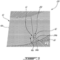
Fig. 3 is a schematic cross-sectional fragmented view taken on a plane disposed between blades of an impeller in accordance with one embodiment; -
Fig. 4 is a schematic three dimensional view of one of the blades of the impeller ofFig. 3 ; -
Fig. 5 is a schematic cross-sectional fragmented view taken on a plane disposed between blades of an impeller in accordance with another embodiment; -
Fig. 6 illustrates three dimensional streamlines on the baseline impeller ofFig. 2 ; -
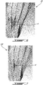
Fig. 7 illustrates three dimensional streamlines on the impeller ofFig. 3 ; -
Fig. 8 shows velocity contours on a cross-section of a diffuser conduit of a diffuser of the compressor of the gas turbine engine ofFig. 1 using the baseline impeller ofFig. 2 ; -
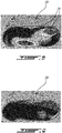
Fig. 9 shows velocity contours on a cross-section of the diffuser conduit of the diffuser of the compressor of the gas turbine ofFig. 1 using the impeller ofFig. 3 ; and -
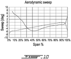
Fig. 10 is a graph illustrating a variation of an aerodynamic sweep angle in function of a span for the blades of the impeller ofFig. 2 (dashed line) and for the blades of the impeller ofFig. 3 (solid line). -
Fig. 1 illustrates agas turbine engine 10 of a type preferably provided for use in subsonic flight, generally comprising in serial flow communication afan 12 through which ambient air is propelled, acompressor section 14 for pressurizing the air, acombustor 16 in which the compressed air is mixed with fuel and ignited for generating an annular stream of hot combustion gases, and aturbine section 18 for extracting energy from the combustion gases. Thefan 12, thecompressor section 14, and theturbine section 18 are configured for rotation about alongitudinal axis 11 of thegas turbine engine 10. - In the embodiment shown, the
compressor section 14 includes a low-pressure compressor 14a and a high-pressure compressor 14b located downstream of the low-pressure compressor 14a. In the depicted embodiment, the high-pressure compressor 14b includes a centrifugal compressor having animpeller 20 rotating within a shroud. The high-pressure compressor 14b further includes a diffuser case assembly havingdiffuser conduits 19 located downstream of an outlet of theimpeller 20. Thediffuser conduits 19 are used to further increase the pressure of the air circulating therethrough and to redirect the air from a substantially radial direction to a substantially axial direction relative to thecentral axis 11 of thegas turbine engine 10. - Referring now to
Fig. 2 , theimpeller 20 is configured for rotation about a rotational axis R, which, in the embodiment shown, is coincident with the enginelongitudinal axis 11. Theimpeller 20 has ahub 22 having an axial-to-radial shape. Stated otherwise, in use, a flow of working fluid circulates substantially tangentially to asurface 24 of thehub 22. The flow, in anupstream location 26 of theimpeller 20, is aligned substantially axially relative to the axis R and, in adownstream location 28, is aligned substantially radially relative to the axis R. In other words, the flow circulates generally parallel to the axis R when entering theimpeller 20 and generally perpendicularly to the axis R, and away therefrom, when exiting theimpeller 20. If theimpeller 20 is used as a turbine impeller instead of a compressor impeller, this arrangement is opposite. - The
impeller 20 further includesblades 30 disposed on thehub 22. Theblades 30 havepressure sides 32 andsuction sides 34. The pressure andsuction sides roots 35, at thehub 22, towardtips 36 of theblades 30 and from leadingedges 38 towardtrailing edges 40 of theblades 30. The blade leading andtrailing edges hub 22 and the tips of theblades 36 are spaced apart from one another by spans S (Fig. 3 ). Theblades 30 extend along their spans S from theirroots 35 to theirtips 36. - In the embodiment shown, the spans S of the
blades 30 may vary between the leadingsedge 38 and thetrailing edge 40. The span S of theblades 30 may decrease from the leadingedges 38 to thetrailing edges 40. The chords C of theblades 30 may vary between theroots 35 of theblades 30 to theirtips 36. - In the embodiment shown, the
blades 30 includefull blades 42 andsplitter blades 44 circumferentially disposed in alternation around the rotational axis R. Stated otherwise, in an embodiment, one of thesplitter blades 44 may be disposed between each set of adjacent two of thefull blades 42. Chords of thesplitter blades 44 are less than chords of thefull blades 42. In the illustrated embodiment, the chords of thesplitter blades 44 range between 50% to 80% of the chords of thefull blades 42. The main andsplitter blades leading edges edges edges 40 of the main andsplitter blades edges 38 may be offset. The leadingedges 38 of thesplitter blades 44 may be located downstream of theleading edges 38 of themain blades 42. - The
impeller 20 has aflow channel 46 between each adjacent two of thefull blades 42. Theflow channels 46 are configured for receiving an incoming flow at theupstream location 26 and for outletting the flow at thedownstream location 28. Along theflow channels 46, the flow changes direction from generally axially, and parallel to the rotational axis R, to generally radially, and perpendicular to the rotational axis R. A width of each of theflow channels 46 varies from the upstream 26 to the downstream 28 locations. For any given position along the rotational axis R between the upstream 26 and downstream 28 locations, the height of each of theflow channels 46 may be constant in a radial direction from thehub 22 toward theblade tips 36. The width varies along the axis R. The width of each of theflow channels 46 may increase from the upstream 26 to the downstream 28 locations. - The
blade leading edges 38 may be circumferentially offset from theblade trailing edges 40. Consequently, the flow circulating within theflow channels 46 may move around the rotational axis R from theupstream location 26 to thedownstream location 28. In the case of a compressor impeller, this rotation allows the impeller to transfer energy to the working fluid. Alternatively, in the case of a turbine impeller, this rotation allows the impeller to extract energy from the working fluid. - In the embodiment shown, each of the
flow channels 46 is divided in two downstream of theupstream location 26 by thesplitter blades 44. Hence, theflow channels 46 each diverge into afirst flow channel 46a and a second flow channel 46b. Thefirst flow channel 46a is bounded by asuction side 34 of one of thefull blade 42, apressure side 32 of an adjacent one of thesplitter blades 44 and by thehub 22. The second flow channel 46b is bounded by asuction side 34 of the adjacent one of thesplitter blades 44, by apressure side 32 of an adjacent one of thefull blade 42, and by thehub 22. - In some circumstances, secondary flow, generally referred to as three-dimensional vortical flow structures, develops in the first and
second flow channels 46a and 46b due to flow turning and non-uniform inlet pressure profiles. While main flow is responsible for energy extraction/transfer, the secondary flow is transverse to the main flow and acts to reduce energy available for energy extraction/transfer. The secondary flow originates in a boundary layer that flows along theblades 30 and contains a span-wise velocity gradient. When boundary flow is turned, traverse velocity components are introduced. - In some cases, the secondary flow creates cross flows that go from the blade pressure sides 32 to the blade suction sides 34. These flows are carried off the
adjacent suction side 34 from thehub 22 to thetips 36 due to pressure difference and centrifugal force. The secondary flow interacts with main blade tip clearance flow. This interaction may result in mixing loss and flow blockage. The combination of leakage and secondary flow is observed to reach the entire passage and may create large flow blockage. Large flow blockage may lead to premature impeller inducer stalling, or affect performance of downstream components. - Due to the nature of low aspect ratio of the blades 130, there may be strong secondary flow within the
impeller passage 46. The cross flow from the pressure side travels up the suction side to the tip section where it may interact with the tip leakage flow. This may result in high impeller mixing loss and flow non uniformity into the downstream diffuser conduits 19 (Fig. 1 ). The non-uniform flow may be detrimental to diffuser performance. - Referring now to
Figs. 3-4 , an impeller in accordance with another embodiment is generally shown at 120. In the embodiment shown, each of thesplitter blades 144 has acutback section 150. Thecutback section 150 may be created by rounding a corner defined by an intersection of theleading edge 144a of thesplitter blade 144 with thehub 22. In other words, the splitter hub leading corner point is swept back and a curve is formed that may be tangent to both the leading edge and splitter airfoil hub section. - The
cutback section 150 creates a sweep of thesplitter blade 144 at thehub 22. Stated differently, the leadingedge 144a of thesplitter blade 144 extends in an upstream direction as it extends away from the hub. Stated otherwise, the leadingedge 144a of thesplitter blade 144 at the hub may be located downstream of theleading edge 144a at a midspan location relative to a flow circulating between the blades. In other words, a sweep angle A1 between theleading edge 144a of thesplitter blade 144 and thehub 22 may range from about 5 to about 70 degrees, preferably 20 degrees. The sweep angle A1 may be different than 90 degrees. The leadingedges 144a of thesplitter blades 144 may extend in an upstream direction U as the leadingedges 144a extends away from thehub 22 of theimpeller 120. The upstream direction U is taken relative to a flow circulating within theflow passages 46 defined between theblades 30 of theimpeller 120. - The
cutback section 150 extends both in a spanwise direction D1 and in a chordwise direction D2. The spanwise direction D1 extends from the roots to the tips whereas the chordwise direction extends from the leading edges to the trailing edges. Thecutback section 150 may extend along the spanwise direction D1 from thehub 22 to a location L1. The location L1 may be at least at about 5% of the span S of thesplitter blades 144 from thehub 22. The location L1 may be at least at about 10% of the span of thesplitter blades 144 from thehub 22. The location L1 may be at least at about 5% of the span S of thesplitter blades 144; the span S taken at theleading edges 144a of thesplitter blades 144. The location L1 may be at least at about 15% of the span of thesplitter blades 144 from thehub 22; the span S taken at theleading edges 144a of thesplitter blades 144. In a particular embodiment, thecutback section 150 extends from the hub to at most 30% of the span S. - In the depicted embodiment, the
cutback section 150 extends in the chordwise direction D2 along at least about 5% of the chord C of thesplitter blades 144. Thecutback section 150 may extend in the chordwise direction D2 along at least 5% of the chord C of thesplitter blades 144; the chord C taken at the location L1. The leadingedges 144a of thesplitter blades 144 at thehub 22 may be offset from the leadingedges 144a at the location L1 by a distance in the chordwise direction D2 of at least about 5% of the chord C of thesplitter blades 144. In a particular embodiment, the cut-backsection 150 extends along at most 20% of the chord C of thesplitter blades 144. - As shown in
Figs. 3-4 , the leadingedge 144a of thesplitter blade 144 is curved at thecutback section 150. A chord of thesplitter blade 144 may vary non-linearly with a spanwise position along thecutback section 150. Any suitable shape for thecutback section 150 may be used, such as circular and parabolic. A radius of theleading edge 144a of thesplitter blade 144 may range from 5% to 30% of the span S. In the embodiment shown, thecutback section 150 is tangential to a remainder of thesplitter blade 144. In other words, thecutback section 150 of theleading edge 144a of thesplitter blade 144 mergers tangentially to a remainder of theleading edge 144a of thesplitter blade 144 at the location L1. - In a particular embodiment, the chord C of the
splitter blade 144 between thehub 22 and the location L1 may be less than that of thesplitter blade 44 of thebaseline impeller 20 described above with reference toFig. 2 . For the sake of comparison, theleading edge 44a of thesplitter blade 44 of thebaseline impeller 20 ofFig. 2 is shown inFig. 3 with a dashed line. In a particular embodiment, the chord C of thesplitter blade 144 at thehub 22 is less than about 95% of the chord C of thesplitter blade 144 at the location L1. Stated differently, thecutback section 150 may be defined by a decrease in the chord C of thesplitter blade 144 of a least 5% along a distance spanning from the location L1 to thehub 22. - Referring now to
Fig. 5 , another embodiment of an impeller is generally shown at 220. For the sake of conciseness, only elements that differ from theimpeller 120 described herein above with reference toFig. 3 are described herein below. - In the embodiment shown, the
cutback section 250 is straight. In other words, a chord C of the splitter blade 244 may vary linearly with a spanwise position along thecutback section 250. In the embodiment shown, thecutback section 250 is angled relative to a remainder of the splitter blade 244. An angle A2 is defined by theleading edge 244a at the location L1. The angle A3 defined by theleading edge 244a and thehub 22 may range from about 5 degrees to about 70 degrees. A height of thecutback section 250 may range from about 5% to about 30% of the span S at theleading edge 244a of the splitter blades 244. - Although the
cutback sections main blades 42. It is understood that thecutback sections - In a particular embodiment, the
cutback sections hub 22 of theimpeller - Referring now to
Figs. 6-7 , streamlines of flows circulating between the blades of thebaseline impeller 20 ofFig. 2 and between the blades of theimpeller 120 ofFig. 3 are shown. As illustrated inFig. 6 , cross flow travels from the pressure side of themain blade 42, across the flow passage, toward the suction side of the main blade. As this secondary flow crosses into the main passage, it may roll up into vortices V and may be swept downstream by the main flow. - As shown in
Fig. 7 , vortex V' is smaller and the vortices that may be present are of a lesser magnitude than those inFig. 6 . Moving the leading edge of the splitter blade back may allow some leakage flow ahead of the leading edge to go from the pressure side to suction side of the blade. This leakage flow may help to counter some of the cross flow coming from the pressure side of the main blades and may redirect it in the flow direction. The result may reduce cross secondary flow. A comparison ofFigs. 6 and 7 show that there is a reduction in cross flow caused by thecutback sections - The disclosed
impellers Fig. 3 may minimize impeller secondary flow by sweeping the leading edge near the hub in the direction of flow of either the main or splitter blade. Thecutback sections - Referring now to
Figs. 8-9 , velocity contours are shown on a cross-section of one of thediffuser conduits 19 of the high-pressure compressor 14b (Fig. 1 ) with identical scales. As illustrated onFig. 8 , two zones Z1 of low velocities are presented when using thebaseline impeller 20 described above with reference toFig. 2 . As illustrated inFig. 9 , the velocity field is more uniform when using theimpeller Figs. 3 and5 , which definecutback sections - Referring now to
Fig. 10 , a graph illustrates a variation of the aerodynamic sweep angle in function of a spanwise position for theleading edge 44a of thesplitter blade 44 of thebaseline impeller 20 ofFig. 2 (dashed line) and for theleading edge 144a of thesplitter blade 144 of theimpeller 120 ofFig. 3 (solid line). The aerodynamic sweep angle of theleading edge 144a of thesplitter blade 144 is greater than that of theleading edge 44a of thesplitter blade 44a of the baseline impeller at least at thecutback section 150. The aerodynamic sweep angle is defined as an angle between the leading edge of the blade and a direction of an incoming flow. In the embodiment shown, the aerodynamic sweep angle of theleading edge 144a of thesplitter blade 144 is at least about 5 degrees, preferably at least about 10 degrees, greater than the aerodynamic sweep angle of theleading edge 144a at 30% of the span S from thehub 22; the span S being taken at theleading edge 144a. - Still referring to
Fig. 10 , the aerodynamic sweep angle difference between thesplitter blade 44 of thebaseline impeller 20 and thesplitter blade 144 of theimpeller 120 occurs between 0% and 30% of the span S. The difference in aerodynamic sweep angle may be greater than the difference in sweep angle between thebaseline splitter blade 44 and the modifiedsplitter blade 144. This may indicate strong flow redistribution in radial direction due to the cutback. - In a particular embodiment, the blade may be cutback and a beta angle of the blade may be changed to maintain an original sweep distribution (e.g., before the cutback). The beta angle is the blade angle when viewed from top down. Zero degree is the engine centerline and 90 degrees is perpendicular to the engine centerline. By controlling the beta angle distribution, one may define the blade turning or blade shape.
- Embodiments disclosed herein include:
- A. An impeller comprising a hub, blades extending from the hub along respective spans from roots to tips, the blades extending along respective chords from leading edges to trailing edges, the leading edge of at least one of the blades having a cutback section defining a sweep at the root, the cutback section extending in a spanwise direction from the hub to a location at least about 5% of the span from the hub of the at least one of the blades, and the cutback section extending in a chordwise direction along at least about 5% of the chord of the at least one of the blades.
- B. An impeller comprising a hub, blades extending from the hub along respective spans from roots to tips, the blades extending along respective chords from leading edges to trailing edges, the leading edge of at least one of the blades extending in an upstream direction, relative to a flow of air circulating between the blades, and away from the hub to a location corresponding to at least about 5% of the span of the at least one of the blades, the leading edge of the at least one of the blades at the hub being offset from the leading edge of the at least one of the blades at the location by a distance in a chordwise direction of at least about 5% of the chord of the at least one of the blades.
- C. An impeller comprising a hub, blades extending from the hub along respective spans from roots to tips, the blades extending along respective chords from leading edges to trailing edges, the leading edge of at least one of the blades having a mean for decreasing a secondary flow.
- D. An impeller comprising a hub, blades extending from the hub along respective spans from roots to tips, the blades extending along respective chords from leading edges to trailing edges, the leading edge of at least one of the blades having a cutback section defining a sweep at the root, the cutback section extending in a spanwise direction from the hub to a location being at least about 10% of the span of the at least one of the blades from the hub, the chord of the at least one of the blades at the hub less than about 95% of the chord of the at least one of the blades at the location.
- Embodiments A, B, C, and D may include any of the following elements, in any combinations:
Element 1: the cutback section extends in the chordwise direction along at least 5% of the chord of the at least one of the blades at the location. Element 2: the cutback section extends in the chordwise direction along at most 20% of the chord of the at least one of the blades. Element 3: the location is at most at about 30% of the span of the at least one of the blades from the hub. Element 4: the location is at least at about 10% of the span of the at least one of the blades at the leading edge of the at least one of the blades. Element 5: the blades include main blades and splitter blades, each of the splitter blades disposed between two adjacent ones of the main blades, the splitter blades having chord lengths less than that of the main blades, the cutback section defined in leading edges of each of the splitter blades. Element 6: the blades include main blades and splitter blades, each of the splitter blades disposed between two adjacent ones of the main blades, the splitter blades having chord lengths less than that of the main blades, the cutback section defined by leading edges of each of the main blades. Element 7: a sweep angle of the at least one of the blades at the hub ranges from 5 to 70 degrees. Element 8: the sweep angle is about 20 degrees. Element 9: the leading edge of the at least one of the blades is curved at the cutback section. Element 10: the mean is a cutback extending in a spanwise direction from the hub to a location being at least about 5% of the span of the at least one of the blades from the hub and at most 30% of the span from the hub. Element 11: the cutback extends in a chordwise direction along at least 5% of the chord of the at least one of the blades and along at most 20% of the chord. - In the present disclosure including claims, the expression "about" implies that a given value may range from plus or minus 10% of the given value. For instance, a value of about 10 implies that the value may range from 9 to 11.
- The above description is meant to be exemplary only, and one skilled in the art will recognize that changes may be made to the embodiments described without departing from the scope of the invention disclosed. Still other modifications which fall within the scope of the present invention will be apparent to those skilled in the art, in light of a review of this disclosure, and such modifications are intended to fall within the appended claims.
Claims (11)
- An impeller (20) comprising a hub (22) and blades (42, 44, 144, 244) extending from the hub (22) along respective spans (S) from roots (35) to tips (36), the blades (42, 44, 144, 244) extending along respective chords (C) from leading edges (42a, 44a, 144a, 244a) to trailing edges (42b, 44b), the leading edge (42a, 44a, 144a, 244a) of at least one of the blades (42, 44, 144, 244) having a cutback section (150, 250) defining a sweep at the root (35), the cutback section (150, 250) extending in a spanwise direction (D1) from the hub (22) to a location (L1) at least about 5% of the span (S) from the hub (22) of the at least one of the blades (42, 44, 144, 244), and the cutback section (150, 250) extending in a chordwise direction (D2) along at least about 5% of the chord (C) of the at least one of the blades (42, 44, 144, 244).
- The impeller of claim 1, wherein the cutback section (150, 250) extends in the chordwise direction (D2) along at least 5% of the chord (C) of the at least one of the blades (42, 44, 144, 244) at the location (L1).
- The impeller of claim 1 or 2, wherein the cutback section (150, 250) extends in the chordwise direction (D2) along at most 20% of the chord (C) of the at least one of the blades (42, 44, 144, 244).
- The impeller of any preceding claim, wherein the location (L1) is at most at about 30% of the span (S) of the at least one of the blades (42, 44, 144, 244) from the hub (22).
- The impeller of any preceding claim, wherein the location (L1) is at least at about 10% of the span (S) of the at least one of the blades (42, 44, 144, 244) at the leading edge (42a, 44a, 144a, 244a) of the at least one of the blades (42, 44, 144, 244).
- The impeller of any preceding claim, wherein the blades (42, 44, 144, 244) include main blades (42) and splitter blades (44, 144, 244), each of the splitter blades (44, 144, 244) disposed between two adjacent ones of the main blades (42), the splitter blades (44, 144, 244) having chord (C) lengths less than that of the main blades (42), the cutback section (150, 250) defined in leading edges (44a, 144a, 244a) of each of the splitter blades (44, 144, 244).
- The impeller of any preceding claim, wherein the blades (42, 44, 144, 244) include main blades (42) and splitter blades (44, 144, 244), each of the splitter blades (44, 144, 244) disposed between two adjacent ones of the main blades (42), the splitter blades (44, 144, 244) having chord (C) lengths less than that of the main blades (42), the cutback section defined by leading edges (42a) of each of the main blades (42).
- The impeller of any preceding claim, wherein a sweep angle (A1) of the at least one of the blades (144) at the hub (22) ranges from 5 to 70 degrees.
- The impeller of claim 8, wherein the sweep angle (A1) is about 20 degrees.
- The impeller of any preceding claim, wherein the leading edge (144a) of the at least one of the blades (144) is curved at the cutback section (150).
- The impeller of any preceding claim, wherein the cutback section (150, 250) of the leading edge (42a, 44a, 144a, 244a) provides a means for decreasing a secondary flow.
Applications Claiming Priority (1)
| Application Number | Priority Date | Filing Date | Title |
|---|---|---|---|
| US16/692,241 US12018583B2 (en) | 2019-11-22 | 2019-11-22 | Impeller with hub sweep |
Publications (2)
| Publication Number | Publication Date |
|---|---|
| EP3825556A1 true EP3825556A1 (en) | 2021-05-26 |
| EP3825556B1 EP3825556B1 (en) | 2025-12-31 |
Family
ID=73544062
Family Applications (1)
| Application Number | Title | Priority Date | Filing Date |
|---|---|---|---|
| EP20209243.3A Active EP3825556B1 (en) | 2019-11-22 | 2020-11-23 | Wheel with hub scanning |
Country Status (3)
| Country | Link |
|---|---|
| US (1) | US12018583B2 (en) |
| EP (1) | EP3825556B1 (en) |
| CA (1) | CA3100318A1 (en) |
Families Citing this family (1)
| Publication number | Priority date | Publication date | Assignee | Title |
|---|---|---|---|---|
| US12590590B2 (en) * | 2024-02-21 | 2026-03-31 | Pratt & Whitney Canada Corp. | Aircraft engine impeller with exducer shroud forward sweep |
Citations (4)
| Publication number | Priority date | Publication date | Assignee | Title |
|---|---|---|---|---|
| EP2022988A1 (en) * | 2006-05-26 | 2009-02-11 | IHI Corporation | Moving blade of turbofan engine |
| EP2620651A1 (en) * | 2010-12-28 | 2013-07-31 | Mitsubishi Heavy Industries, Ltd. | Centrifugal compressor |
| US20160252100A1 (en) * | 2013-10-16 | 2016-09-01 | United Technologies Corporation | Auxiliary power unit impeller blade |
| EP3364042A1 (en) * | 2017-02-20 | 2018-08-22 | Rolls-Royce plc | Fan for gas turbine engine with mistuned blades |
Family Cites Families (9)
| Publication number | Priority date | Publication date | Assignee | Title |
|---|---|---|---|---|
| US2441432A (en) * | 1945-12-14 | 1948-05-11 | Gen Electric | High-speed rotor |
| DE10340827A1 (en) * | 2003-09-04 | 2005-03-31 | Rolls-Royce Deutschland Ltd & Co Kg | Repair method for a blade of a fluid flow machine |
| US20080229742A1 (en) * | 2007-03-21 | 2008-09-25 | Philippe Renaud | Extended Leading-Edge Compressor Wheel |
| JP5730649B2 (en) * | 2011-04-13 | 2015-06-10 | 株式会社日立製作所 | Impeller and turbomachine having the same |
| US9133849B2 (en) * | 2011-11-09 | 2015-09-15 | Baker Hughes Incorporated | Impeller vane with leading edge enhancement |
| EP3092413B1 (en) | 2014-01-07 | 2020-01-01 | Nuovo Pignone S.r.l. | Centrifugal compressor impeller with non-linear blade leading edge and associated design method |
| US20160245297A1 (en) * | 2015-02-23 | 2016-08-25 | Howden Roots Llc | Impeller comprising variably-dimensioned fillet to secure blades and compressor comprised thereof |
| US10221858B2 (en) | 2016-01-08 | 2019-03-05 | Rolls-Royce Corporation | Impeller blade morphology |
| JP7752467B2 (en) * | 2019-08-29 | 2025-10-10 | 三菱重工コンプレッサ株式会社 | Impeller and centrifugal compressor |
-
2019
- 2019-11-22 US US16/692,241 patent/US12018583B2/en active Active
-
2020
- 2020-11-20 CA CA3100318A patent/CA3100318A1/en active Pending
- 2020-11-23 EP EP20209243.3A patent/EP3825556B1/en active Active
Patent Citations (4)
| Publication number | Priority date | Publication date | Assignee | Title |
|---|---|---|---|---|
| EP2022988A1 (en) * | 2006-05-26 | 2009-02-11 | IHI Corporation | Moving blade of turbofan engine |
| EP2620651A1 (en) * | 2010-12-28 | 2013-07-31 | Mitsubishi Heavy Industries, Ltd. | Centrifugal compressor |
| US20160252100A1 (en) * | 2013-10-16 | 2016-09-01 | United Technologies Corporation | Auxiliary power unit impeller blade |
| EP3364042A1 (en) * | 2017-02-20 | 2018-08-22 | Rolls-Royce plc | Fan for gas turbine engine with mistuned blades |
Also Published As
| Publication number | Publication date |
|---|---|
| US12018583B2 (en) | 2024-06-25 |
| CA3100318A1 (en) | 2021-05-22 |
| US20210156259A1 (en) | 2021-05-27 |
| EP3825556B1 (en) | 2025-12-31 |
Similar Documents
| Publication | Publication Date | Title |
|---|---|---|
| JP3578769B2 (en) | Flow orientation assembly for the compression region of rotating machinery | |
| EP3121383B1 (en) | A turbine stator vane assembly for a turbomachine | |
| EP3026214B1 (en) | Airfoil with stepped spanwise thickness distribution | |
| JP5386076B2 (en) | The latest booster system | |
| US11225870B2 (en) | Impeller splitter optimization | |
| EP0040534A1 (en) | Compressor diffuser | |
| EP3231996B1 (en) | A blade for an axial flow machine | |
| US12071959B1 (en) | Compressor casing with slots and grooves | |
| CN114837994A (en) | Turbine engine with cross flow reduced airfoils | |
| CN102459916B (en) | Centrifugal impeller for a compressor | |
| EP3098383B1 (en) | Compressor airfoil with compound leading edge profile | |
| US11939880B1 (en) | Airfoil assembly with flow surface | |
| EP3825556B1 (en) | Wheel with hub scanning | |
| CN116201605A (en) | Airfoil profile for a blade in a turbine engine | |
| EP3783228B1 (en) | Impeller with chordwise vane thickness variation | |
| US10495095B2 (en) | Multistage compressor with aerofoil portion profiled in a spanwise direction | |
| US12540555B2 (en) | Stator part having a fin, in a turbine engine | |
| EP4144958B1 (en) | Fluid machine for an aircraft engine and aircraft engine | |
| US12196087B2 (en) | Turbine engine with a rotating blade having a fin |
Legal Events
| Date | Code | Title | Description |
|---|---|---|---|
| PUAI | Public reference made under article 153(3) epc to a published international application that has entered the european phase |
Free format text: ORIGINAL CODE: 0009012 |
|
| STAA | Information on the status of an ep patent application or granted ep patent |
Free format text: STATUS: THE APPLICATION HAS BEEN PUBLISHED |
|
| AK | Designated contracting states |
Kind code of ref document: A1 Designated state(s): AL AT BE BG CH CY CZ DE DK EE ES FI FR GB GR HR HU IE IS IT LI LT LU LV MC MK MT NL NO PL PT RO RS SE SI SK SM TR |
|
| STAA | Information on the status of an ep patent application or granted ep patent |
Free format text: STATUS: REQUEST FOR EXAMINATION WAS MADE |
|
| 17P | Request for examination filed |
Effective date: 20211126 |
|
| RBV | Designated contracting states (corrected) |
Designated state(s): AL AT BE BG CH CY CZ DE DK EE ES FI FR GB GR HR HU IE IS IT LI LT LU LV MC MK MT NL NO PL PT RO RS SE SI SK SM TR |
|
| STAA | Information on the status of an ep patent application or granted ep patent |
Free format text: STATUS: EXAMINATION IS IN PROGRESS |
|
| 17Q | First examination report despatched |
Effective date: 20230213 |
|
| GRAP | Despatch of communication of intention to grant a patent |
Free format text: ORIGINAL CODE: EPIDOSNIGR1 |
|
| STAA | Information on the status of an ep patent application or granted ep patent |
Free format text: STATUS: GRANT OF PATENT IS INTENDED |
|
| INTG | Intention to grant announced |
Effective date: 20250721 |
|
| GRAS | Grant fee paid |
Free format text: ORIGINAL CODE: EPIDOSNIGR3 |
|
| GRAA | (expected) grant |
Free format text: ORIGINAL CODE: 0009210 |
|
| STAA | Information on the status of an ep patent application or granted ep patent |
Free format text: STATUS: THE PATENT HAS BEEN GRANTED |
|
| AK | Designated contracting states |
Kind code of ref document: B1 Designated state(s): AL AT BE BG CH CY CZ DE DK EE ES FI FR GB GR HR HU IE IS IT LI LT LU LV MC MK MT NL NO PL PT RO RS SE SI SK SM TR |
|
| REG | Reference to a national code |
Ref country code: CH Ref legal event code: F10 Free format text: ST27 STATUS EVENT CODE: U-0-0-F10-F00 (AS PROVIDED BY THE NATIONAL OFFICE) Effective date: 20251231 Ref country code: GB Ref legal event code: FG4D |
|
| REG | Reference to a national code |
Ref country code: DE Ref legal event code: R096 Ref document number: 602020064693 Country of ref document: DE |
|
| REG | Reference to a national code |
Ref country code: IE Ref legal event code: FG4D |
|
| REG | Reference to a national code |
Ref country code: LT Ref legal event code: MG9D |
|
| PG25 | Lapsed in a contracting state [announced via postgrant information from national office to epo] |
Ref country code: NO Free format text: LAPSE BECAUSE OF FAILURE TO SUBMIT A TRANSLATION OF THE DESCRIPTION OR TO PAY THE FEE WITHIN THE PRESCRIBED TIME-LIMIT Effective date: 20260331 |
|
| PG25 | Lapsed in a contracting state [announced via postgrant information from national office to epo] |
Ref country code: FI Free format text: LAPSE BECAUSE OF FAILURE TO SUBMIT A TRANSLATION OF THE DESCRIPTION OR TO PAY THE FEE WITHIN THE PRESCRIBED TIME-LIMIT Effective date: 20251231 Ref country code: HR Free format text: LAPSE BECAUSE OF FAILURE TO SUBMIT A TRANSLATION OF THE DESCRIPTION OR TO PAY THE FEE WITHIN THE PRESCRIBED TIME-LIMIT Effective date: 20251231 |
|
| PG25 | Lapsed in a contracting state [announced via postgrant information from national office to epo] |
Ref country code: RS Free format text: LAPSE BECAUSE OF FAILURE TO SUBMIT A TRANSLATION OF THE DESCRIPTION OR TO PAY THE FEE WITHIN THE PRESCRIBED TIME-LIMIT Effective date: 20260331 |
|
| PG25 | Lapsed in a contracting state [announced via postgrant information from national office to epo] |
Ref country code: LV Free format text: LAPSE BECAUSE OF FAILURE TO SUBMIT A TRANSLATION OF THE DESCRIPTION OR TO PAY THE FEE WITHIN THE PRESCRIBED TIME-LIMIT Effective date: 20251231 |
|
| PG25 | Lapsed in a contracting state [announced via postgrant information from national office to epo] |
Ref country code: BG Free format text: LAPSE BECAUSE OF FAILURE TO SUBMIT A TRANSLATION OF THE DESCRIPTION OR TO PAY THE FEE WITHIN THE PRESCRIBED TIME-LIMIT Effective date: 20251231 |
|
| REG | Reference to a national code |
Ref country code: NL Ref legal event code: MP Effective date: 20251231 |
|
| REG | Reference to a national code |
Ref country code: AT Ref legal event code: MK05 Ref document number: 1873528 Country of ref document: AT Kind code of ref document: T Effective date: 20251231 |
|
| PG25 | Lapsed in a contracting state [announced via postgrant information from national office to epo] |
Ref country code: NL Free format text: LAPSE BECAUSE OF FAILURE TO SUBMIT A TRANSLATION OF THE DESCRIPTION OR TO PAY THE FEE WITHIN THE PRESCRIBED TIME-LIMIT Effective date: 20251231 |
|
| PG25 | Lapsed in a contracting state [announced via postgrant information from national office to epo] |
Ref country code: LT Free format text: LAPSE BECAUSE OF FAILURE TO SUBMIT A TRANSLATION OF THE DESCRIPTION OR TO PAY THE FEE WITHIN THE PRESCRIBED TIME-LIMIT Effective date: 20251231 |
|
| PG25 | Lapsed in a contracting state [announced via postgrant information from national office to epo] |
Ref country code: SM Free format text: LAPSE BECAUSE OF FAILURE TO SUBMIT A TRANSLATION OF THE DESCRIPTION OR TO PAY THE FEE WITHIN THE PRESCRIBED TIME-LIMIT Effective date: 20251231 |
|
| PG25 | Lapsed in a contracting state [announced via postgrant information from national office to epo] |
Ref country code: ES Free format text: LAPSE BECAUSE OF FAILURE TO SUBMIT A TRANSLATION OF THE DESCRIPTION OR TO PAY THE FEE WITHIN THE PRESCRIBED TIME-LIMIT Effective date: 20251231 |
|
| PG25 | Lapsed in a contracting state [announced via postgrant information from national office to epo] |
Ref country code: PL Free format text: LAPSE BECAUSE OF FAILURE TO SUBMIT A TRANSLATION OF THE DESCRIPTION OR TO PAY THE FEE WITHIN THE PRESCRIBED TIME-LIMIT Effective date: 20251231 |
|
| PG25 | Lapsed in a contracting state [announced via postgrant information from national office to epo] |
Ref country code: IT Free format text: LAPSE BECAUSE OF FAILURE TO SUBMIT A TRANSLATION OF THE DESCRIPTION OR TO PAY THE FEE WITHIN THE PRESCRIBED TIME-LIMIT Effective date: 20251231 |
|
| PG25 | Lapsed in a contracting state [announced via postgrant information from national office to epo] |
Ref country code: AT Free format text: LAPSE BECAUSE OF FAILURE TO SUBMIT A TRANSLATION OF THE DESCRIPTION OR TO PAY THE FEE WITHIN THE PRESCRIBED TIME-LIMIT Effective date: 20251231 |
|
| PG25 | Lapsed in a contracting state [announced via postgrant information from national office to epo] |
Ref country code: EE Free format text: LAPSE BECAUSE OF FAILURE TO SUBMIT A TRANSLATION OF THE DESCRIPTION OR TO PAY THE FEE WITHIN THE PRESCRIBED TIME-LIMIT Effective date: 20251231 |
|
| PG25 | Lapsed in a contracting state [announced via postgrant information from national office to epo] |
Ref country code: IS Free format text: LAPSE BECAUSE OF FAILURE TO SUBMIT A TRANSLATION OF THE DESCRIPTION OR TO PAY THE FEE WITHIN THE PRESCRIBED TIME-LIMIT Effective date: 20260430 Ref country code: PT Free format text: LAPSE BECAUSE OF FAILURE TO SUBMIT A TRANSLATION OF THE DESCRIPTION OR TO PAY THE FEE WITHIN THE PRESCRIBED TIME-LIMIT Effective date: 20260430 |
|
| PG25 | Lapsed in a contracting state [announced via postgrant information from national office to epo] |
Ref country code: CZ Free format text: LAPSE BECAUSE OF FAILURE TO SUBMIT A TRANSLATION OF THE DESCRIPTION OR TO PAY THE FEE WITHIN THE PRESCRIBED TIME-LIMIT Effective date: 20251231 |
|
| PG25 | Lapsed in a contracting state [announced via postgrant information from national office to epo] |
Ref country code: SK Free format text: LAPSE BECAUSE OF FAILURE TO SUBMIT A TRANSLATION OF THE DESCRIPTION OR TO PAY THE FEE WITHIN THE PRESCRIBED TIME-LIMIT Effective date: 20251231 |
|
| PG25 | Lapsed in a contracting state [announced via postgrant information from national office to epo] |
Ref country code: SE Free format text: LAPSE BECAUSE OF FAILURE TO SUBMIT A TRANSLATION OF THE DESCRIPTION OR TO PAY THE FEE WITHIN THE PRESCRIBED TIME-LIMIT Effective date: 20251231 |