EP3825476A1 - Method for controlling the hydraulic aggressiveness of a work vehicle - Google Patents
Method for controlling the hydraulic aggressiveness of a work vehicle Download PDFInfo
- Publication number
- EP3825476A1 EP3825476A1 EP20209117.9A EP20209117A EP3825476A1 EP 3825476 A1 EP3825476 A1 EP 3825476A1 EP 20209117 A EP20209117 A EP 20209117A EP 3825476 A1 EP3825476 A1 EP 3825476A1
- Authority
- EP
- European Patent Office
- Prior art keywords
- parameter
- input parameter
- function
- elaboration
- work vehicle
- Prior art date
- Legal status (The legal status is an assumption and is not a legal conclusion. Google has not performed a legal analysis and makes no representation as to the accuracy of the status listed.)
- Granted
Links
Images

Classifications
-
- E—FIXED CONSTRUCTIONS
- E02—HYDRAULIC ENGINEERING; FOUNDATIONS; SOIL SHIFTING
- E02F—DREDGING; SOIL-SHIFTING
- E02F9/00—Component parts of dredgers or soil-shifting machines, not restricted to one of the kinds covered by groups E02F3/00 - E02F7/00
- E02F9/20—Drives; Control devices
- E02F9/22—Hydraulic or pneumatic drives
- E02F9/2253—Controlling the travelling speed of vehicles, e.g. adjusting travelling speed according to implement loads, control of hydrostatic transmission
-
- B—PERFORMING OPERATIONS; TRANSPORTING
- B66—HOISTING; LIFTING; HAULING
- B66F—HOISTING, LIFTING, HAULING OR PUSHING, NOT OTHERWISE PROVIDED FOR, e.g. DEVICES WHICH APPLY A LIFTING OR PUSHING FORCE DIRECTLY TO THE SURFACE OF A LOAD
- B66F9/00—Devices for lifting or lowering bulky or heavy goods for loading or unloading purposes
- B66F9/06—Devices for lifting or lowering bulky or heavy goods for loading or unloading purposes movable, with their loads, on wheels or the like, e.g. fork-lift trucks
- B66F9/075—Constructional features or details
- B66F9/20—Means for actuating or controlling masts, platforms, or forks
- B66F9/22—Hydraulic devices or systems
-
- E—FIXED CONSTRUCTIONS
- E02—HYDRAULIC ENGINEERING; FOUNDATIONS; SOIL SHIFTING
- E02F—DREDGING; SOIL-SHIFTING
- E02F9/00—Component parts of dredgers or soil-shifting machines, not restricted to one of the kinds covered by groups E02F3/00 - E02F7/00
- E02F9/20—Drives; Control devices
- E02F9/2004—Control mechanisms, e.g. control levers
-
- F—MECHANICAL ENGINEERING; LIGHTING; HEATING; WEAPONS; BLASTING
- F16—ENGINEERING ELEMENTS AND UNITS; GENERAL MEASURES FOR PRODUCING AND MAINTAINING EFFECTIVE FUNCTIONING OF MACHINES OR INSTALLATIONS; THERMAL INSULATION IN GENERAL
- F16H—GEARING
- F16H59/00—Control inputs to control units of change-speed- or reversing-gearings for conveying rotary motion
- F16H59/36—Inputs being a function of speed
- F16H59/38—Inputs being a function of speed of gearing elements
- F16H2059/385—Turbine speed
-
- F—MECHANICAL ENGINEERING; LIGHTING; HEATING; WEAPONS; BLASTING
- F16—ENGINEERING ELEMENTS AND UNITS; GENERAL MEASURES FOR PRODUCING AND MAINTAINING EFFECTIVE FUNCTIONING OF MACHINES OR INSTALLATIONS; THERMAL INSULATION IN GENERAL
- F16H—GEARING
- F16H59/00—Control inputs to control units of change-speed- or reversing-gearings for conveying rotary motion
- F16H59/36—Inputs being a function of speed
- F16H59/44—Inputs being a function of speed dependent on machine speed, e.g. the vehicle speed
-
- F—MECHANICAL ENGINEERING; LIGHTING; HEATING; WEAPONS; BLASTING
- F16—ENGINEERING ELEMENTS AND UNITS; GENERAL MEASURES FOR PRODUCING AND MAINTAINING EFFECTIVE FUNCTIONING OF MACHINES OR INSTALLATIONS; THERMAL INSULATION IN GENERAL
- F16H—GEARING
- F16H59/00—Control inputs to control units of change-speed- or reversing-gearings for conveying rotary motion
- F16H59/68—Inputs being a function of gearing status
- F16H59/70—Inputs being a function of gearing status dependent on the ratio established
-
- F—MECHANICAL ENGINEERING; LIGHTING; HEATING; WEAPONS; BLASTING
- F16—ENGINEERING ELEMENTS AND UNITS; GENERAL MEASURES FOR PRODUCING AND MAINTAINING EFFECTIVE FUNCTIONING OF MACHINES OR INSTALLATIONS; THERMAL INSULATION IN GENERAL
- F16H—GEARING
- F16H61/00—Control functions within control units of change-speed- or reversing-gearings for conveying rotary motion ; Control of exclusively fluid gearing, friction gearing, gearings with endless flexible members or other particular types of gearing
- F16H61/0021—Generation or control of line pressure
Definitions
- the present invention concerns a method for controlling a hydraulic circuit of a work vehicle, in particular a method for controlling the aggressiveness of such hydraulic circuit.
- Work vehicles such as telehandlers comprise a hydraulic power circuit configured to provide oil at high pressure to allow the movement of hydraulic actuated elements such as actuators or arms.
- such hydraulic actuated elements are controlled via a joystick configured to be handled by the user and moved with respect to a rest position.
- the movement is transformed into a command signal, e.g. an electric signal, that is sent to valves that are voted to the control of oil flow in the aforementioned hydraulic power circuit.
- the speed of the vehicle is a crucial parameter which deeply influences the operating conditions of the vehicle and the way the user handles the joystick. Indeed, if the speed of the vehicle increases, the engine speed increases as well and subsequently also the responsiveness/aggressiveness of the hydraulic power circuit. In fact, the hydraulic power depends on the engine speed, indeed the more speed is provided to its output shaft by the engine, the more the pump may generates hydraulic power.
- the hydraulic power is lower and it is useful for the user to increase responsiveness/aggressiveness of the hydraulic power circuit, i.e. there is a higher shape, maximum control signal value and an anticipation of the dead band.
- the responsiveness/aggressiveness of the vehicle i.e. the capability of the hydraulic power circuit to accomplish with efficiency its tasks, is function of the velocity of the vehicle, i.e. with its motion.
- a control unit can vary accordingly the aforementioned parameters of the joystick so that the hydraulic power circuit can respond in a quick and efficient way.
- all the possible operation of the vehicle cannot be neither included nor foreseen according to the specific use condition of the vehicle.
- An aim of the present invention is to satisfy the above mentioned needs.
- Figure 1 shows schematically the operational relationships between different elements of a work vehicle (not shown) such as a telehandler.
- an engine 1 of the vehicle e.g. an internal combustion engine, is configured to provide a torque between a torque converter 2 and a hydraulic pump 3 configured to pump fluid into a hydraulic power circuit (not shown) of the vehicle and configured to actuate an hydraulic actuated elements such as a boom.
- the hydraulic pump 3 is controlled by piloting valves 5 and manifolds 4 that are in turn controlled by a an electronic unit 6.
- the torque converter 2 is configured to provide torque via a clutch system 7 to a transmission module 8; this latter will provide the torque to wheels 8a via axles 8b through a system of gears 8c, as known in the art and not discussed into detail.
- the work vehicle further comprises a driveline controller 9 configured to control clutches 7 so as to change the transmission ratio of the transmission module 8, i.e. to vary the ratio between the input shaft 2' and the output shaft 8'.
- a driveline controller 9 configured to control clutches 7 so as to change the transmission ratio of the transmission module 8, i.e. to vary the ratio between the input shaft 2' and the output shaft 8'.
- Such driveline controller 9 is actuated by the operator and, as known, may be controlled either manually or electronically.
- the electronic unit 6 implements a control method, described thereinafter, to continuously control the work status of the vehicle and control accordingly the hydraulic pump 3, as described, via piloting valves 5 and manifold 4.
- the electronic unit 6 may be a vehicle control module, e.g. the ECU of the vehicle and, obviously comprises elaboration means configured to memorize and elaborate values received as input as electronic signals and provide an electronic signal as output.
- vehicle control module e.g. the ECU of the vehicle and, obviously comprises elaboration means configured to memorize and elaborate values received as input as electronic signals and provide an electronic signal as output.
- the work vehicle further comprises a joystick 10, of known typology and configured to be electrically connected to electronic unit 6 in order to transmit an output signal according to the run imparted by the user.
- a joystick 10 of known typology and configured to be electrically connected to electronic unit 6 in order to transmit an output signal according to the run imparted by the user.
- the electronic unit 6 receives as inputs four parameters P 1 , P 2 , P 3 and P 4 , elaborates these latter through an elaboration step 100 as described hereunder and provides an output signal O configured to control the valves 3 as disclosed above.
- the elaboration step 100 of the aforementioned four parameters comprises a first stage of elaboration 101 of at least some of the aforementioned input parameters for providing intermediate parameters P 5 , P 6 , P 7 and a second stage of elaboration 102 into which the intermediate parameters P 5 , P 6 , P 7 are elaborated together with at least one of the aforementioned input parameters for providing the above mentioned output signal O.
- the first stage of elaboration 101 comprises a first computational block 103 configured to elaborate the first input parameter P 1 , i.e. the output shaft speed to obtain the first intermediate parameter P 5 .
- the maximum available current for piloting valves 5 is computed according to actual vehicle ground speed.
- the vehicle ground speed is estimated via the value of output shaft speed and the wheel rolling circumference, memorized in the electronic unit 4 in advance and settable by the user, e.g. via a display.
- the relationship between the maximum available current and the vehicle ground speed may be an interpolating function (e.g. linear, parabolic, etc.). Generally, low speed corresponds to maximum value of the current, whilst low speed to minimum value of the current.
- the shape of the interpolating function can be selected by the operator via a display and a plurality of different configuration may be foreseen.
- the configuration may be in a limited number, e.g. three presets (soft corresponds to 0%, medium to 50% and hard to 100%) or via a continuous value (percentage on advanced models).
- three presets soft corresponds to 0%, medium to 50% and hard to 100%
- a continuous value percentage on advanced models
- the first stage of elaboration 101 comprises a second computational block 104 and a third computational block 105; the second computational block 104 is configured to elaborate the first, second and third input parameters P 1 , P 2 , P 3 to estimate a secondary input parameter P 8 used for the computation of a third computational block 105 comprised by the first stage of elaboration 101.
- the second computational block 104 estimates the sliding factor of torque converter 2 in percentage. Such estimation is run in parallel to the computation of first computational block 103. The estimation is based on the input and output shaft speeds (i.e. the first and second input parameters P 1 , P 2 ) to compute a target input shaft speed by knowing the actual engaged gear (i.e. third input parameter) therefore via transmission ratio.
- the target input speed may be calculated by using the measured input speed while knowing the engaged gear.
- some vehicle conditions are preferably evaluated to avoid numerical errors, namely:
- the above mentioned third computational block 105 run subsequently to first and second computational blocks 103, 104, is configured to elaborate the input parameter P 1 and the secondary input parameter P 8 to obtain the second intermediate parameter P 6 , i.e. the value of the minimum current value for piloting valves 5 and P 7 , i.e. a selection signal which can assume a discrete value, as described below.
- the vehicle is considered under heavy load. This means, it is not carrying out a precision maneuver but a power motion (e.g. digging, loading, etc).
- a threshold e.g. 70%
- the curve moves to a logarithmic function (fixed within the controller, by the third value of P 7 as described below) and the minimum current jumps to its maximum allowable value.
- a threshold e.g. 70% (i.e. high load for the engine and very low ground speed)
- the value of vehicle speed is used to change the shape of the current versus joystick deflection curve using the P 7 signal (e.g. moving from linear to parabolic).
- a parabolic curve implies that in the first part of joystick deflection, the current gradient respect to joystick position is smaller (i.e., less responsiveness).
- the computational block 105 changes the minimum current value to its minimum allowable value.
- the threshold e.g. 10kph
- the P 7 depends on torque converter sliding factor sf.
- the second stage of elaboration 102 comprises a single computation block 106 into receiving as input the first, second and third intermediate parameters P 5 , P 6 and P 7 and the fourth input parameter, i.e. position of the joystick.
- the single computation block 106 comprises a mathematical computation of the aforementioned parameters so as to retrieve the value of current to provide as output.
- the mathematical computation comprises different equations according to the status of the third intermediate parameter P 7 .
- the mathematical computation comprises different equations according to the status of the third intermediate parameter P 7 .
- the mathematical computation comprises different equations according to the status of the third intermediate parameter P 7 .
- coefficients b and f are memorized in the electronic control unit 6 and can be calibrated vehicle per vehicle during its validation.
- both values represents the slope of the curve defined by the equation and therefore represents the responsiveness/aggressiveness of the system. Indeed, the greater it is, the greater is the responsiveness/aggressiveness of the system and viceversa.
- the other coefficients are calculated on-time by forcing the related equation to pass from a couple of points of pre-set values.
- the first point is then assumed (0,1; P 6 ) and the second point (0,9; P 5 ), wherein the values of P 6 and P 5 have been already computed in the preceding blocks.
- control method may be elaborated automatically by the work vehicle or can be selected (or unselected) by the user by pushing a specific button or selecting a specific command.
- the work vehicle will adapt itself the hydraulic characteristics without asking to the driver to perform a dedicated action, i.e. to select some predefined configurations.
- the performances of the hydraulic power circuit of a vehicle are optimized for the current working operation, thereby improving the comfort of the operator and the efficiency in the operation he is performing.
- the data retrieved to the use of the vehicle and the related hydraulic power circuit may be memorized and used for supervisory and maintenance aims.
Landscapes
- Engineering & Computer Science (AREA)
- Structural Engineering (AREA)
- Civil Engineering (AREA)
- Transportation (AREA)
- Mining & Mineral Resources (AREA)
- General Engineering & Computer Science (AREA)
- Chemical & Material Sciences (AREA)
- Combustion & Propulsion (AREA)
- Life Sciences & Earth Sciences (AREA)
- Geology (AREA)
- Mechanical Engineering (AREA)
- Control Of Transmission Device (AREA)
Abstract
Description
- The present invention concerns a method for controlling a hydraulic circuit of a work vehicle, in particular a method for controlling the aggressiveness of such hydraulic circuit.
- Work vehicles such as telehandlers comprise a hydraulic power circuit configured to provide oil at high pressure to allow the movement of hydraulic actuated elements such as actuators or arms.
- In particular, such hydraulic actuated elements are controlled via a joystick configured to be handled by the user and moved with respect to a rest position. The movement is transformed into a command signal, e.g. an electric signal, that is sent to valves that are voted to the control of oil flow in the aforementioned hydraulic power circuit.
- In particular, there are four parameters that can be regulated in order to vary the responsiveness/aggressiveness of the hydraulic power circuit in response to a movement of the joystick. Such parameters are:
- A dead band, i.e. a physical minimum length of movement of the joystick with respect to its rest position in order to appreciate the generation of a command signal, i.e. a minimum current for activating the valves of the hydraulic power circuit;
- A maximum control signal value, e.g. a maximum current signal value, i.e. a maximum fluid flow which can pass through the valves of the hydraulic power circuit;
- Shape, i.e. the control signal versus joystick position curve (e.g., mathematical equation which converts the joystick deflection from rest position to a control signal between minimum and maximum values aforementioned); and
- A dynamic parameter, i.e. the time constant of a low-pass filter, configured to avoid the transmission of movement of the joystick due to vibrations, e.g. imparted during the movement on a steep terrain.
- Normally, the speed of the vehicle is a crucial parameter which deeply influences the operating conditions of the vehicle and the way the user handles the joystick. Indeed, if the speed of the vehicle increases, the engine speed increases as well and subsequently also the responsiveness/aggressiveness of the hydraulic power circuit. In fact, the hydraulic power depends on the engine speed, indeed the more speed is provided to its output shaft by the engine, the more the pump may generates hydraulic power.
- In this condition, normally, the operator touches the joystick only for small movements and corrections, in fact the heavy hydraulic tasks are performed at low vehicle speed. While driving, the maximum power availability works against the small corrections desired by the user (i.e., the same joystick position causes a greater hydraulic motion when engine speed is high rather than it is low).
- Accordingly, he slightly moves the joystick to achieve small corrections, but his operation is worsened by steep ground. Since the engine speed cannot be reduced because of desired vehicle speed, it is necessary to adapt control signal to piloting valves to decrease its responsiveness (e.g., the shape and the maximum control signal value).
- Conversely, at low speed/gears, the hydraulic power is lower and it is useful for the user to increase responsiveness/aggressiveness of the hydraulic power circuit, i.e. there is a higher shape, maximum control signal value and an anticipation of the dead band.
- Accordingly, the responsiveness/aggressiveness of the vehicle, i.e. the capability of the hydraulic power circuit to accomplish with efficiency its tasks, is function of the velocity of the vehicle, i.e. with its motion.
- It is known to provide different "typologies" of work conditions of the vehicle that the user may select before starting such specific work operation. A control unit can vary accordingly the aforementioned parameters of the joystick so that the hydraulic power circuit can respond in a quick and efficient way. However, it is clear that all the possible operation of the vehicle cannot be neither included nor foreseen according to the specific use condition of the vehicle.
- Therefore, the need is felt to provide a control method for managing a power hydraulic circuit in order to adjust its responsiveness/aggressiveness, i.e. its velocity of reaction to inputs given by the user and its efficiency.
- An aim of the present invention is to satisfy the above mentioned needs.
- The aforementioned aim is reached by a control method as claimed in the appended set of claims.
- For a better understanding of the present invention, a preferred embodiment is described in the following, by way of a non-limiting example, with reference to the attached drawings wherein:
-
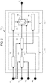
Figure 1 is a diagram illustrating the relationship among different elements controlling the control of a hydraulic power circuit; and -
Figure 2 is a diagram illustrating a control method for varying the operational characteristic of a hydraulic power circuit of a work vehicle according to the invention. -
Figure 1 shows schematically the operational relationships between different elements of a work vehicle (not shown) such as a telehandler. - In particular, an
engine 1 of the vehicle, e.g. an internal combustion engine, is configured to provide a torque between atorque converter 2 and ahydraulic pump 3 configured to pump fluid into a hydraulic power circuit (not shown) of the vehicle and configured to actuate an hydraulic actuated elements such as a boom. - The
hydraulic pump 3 is controlled bypiloting valves 5 andmanifolds 4 that are in turn controlled by a anelectronic unit 6. - The
torque converter 2 is configured to provide torque via aclutch system 7 to atransmission module 8; this latter will provide the torque towheels 8a viaaxles 8b through a system ofgears 8c, as known in the art and not discussed into detail. - As known, it is noticed that the velocity in input via an input shaft 2' upstream with
respect clutches 7 is different with respect to the velocity of an output shaft 8' downstream withrespect clutches 7. - The work vehicle further comprises a
driveline controller 9 configured to controlclutches 7 so as to change the transmission ratio of thetransmission module 8, i.e. to vary the ratio between the input shaft 2' and the output shaft 8'.Such driveline controller 9 is actuated by the operator and, as known, may be controlled either manually or electronically. - Notwithstanding the way in which the
driveline controller 9 is activated by the user, this latter is electrically connected to theelectronic unit 6 that can acquire data related to the operation of theclutches 7 andtransmission module 8. - According to the invention, the
electronic unit 6 implements a control method, described thereinafter, to continuously control the work status of the vehicle and control accordingly thehydraulic pump 3, as described, viapiloting valves 5 andmanifold 4. - Preferably, the
electronic unit 6 may be a vehicle control module, e.g. the ECU of the vehicle and, obviously comprises elaboration means configured to memorize and elaborate values received as input as electronic signals and provide an electronic signal as output. - The work vehicle further comprises a
joystick 10, of known typology and configured to be electrically connected toelectronic unit 6 in order to transmit an output signal according to the run imparted by the user. - As schematically shown in
figure 2 , theelectronic unit 6 receives as inputs four parameters P1, P2, P3 and P4, elaborates these latter through anelaboration step 100 as described hereunder and provides an output signal O configured to control thevalves 3 as disclosed above. - In greater particular:
- The first input parameter P1 is the output shaft speed, in rpm, i.e. the speed of the output shaft 8' of the
transmission module 8; - The second input parameter P2 is the input shaft speed, in rpm, i.e. the speed of the input shaft 2' coupled to the
torque converter 2; - The third input parameter P3 is an information indicative of the gear selected by the
transmission module 8; and - The fourth input parameter P4 is an information indicative of a joystick position.
- The
elaboration step 100 of the aforementioned four parameters comprises a first stage ofelaboration 101 of at least some of the aforementioned input parameters for providing intermediate parameters P5, P6, P7 and a second stage ofelaboration 102 into which the intermediate parameters P5, P6, P7 are elaborated together with at least one of the aforementioned input parameters for providing the above mentioned output signal O. - In grater particular:
- The first intermediate parameter P5 is a maximum current value, in mA, representing the maximum current available for piloting the
valves 5; - The second intermediate parameter P6 is a minimum current value, in mA, representing the minimum current available for piloting the
valves 5; and - The third intermediate parameter P7 is a current curve shape selection which may assume three different values, e.g. 0 i.e. parabolic, 1 i.e. linear or 2 i.e. logarithmic.
- In the following, the first stage of
elaboration 101 into which some of the aforementioned input parameters are elaborated for providing intermediate parameters P5, P6, P7 will be described. - The first stage of
elaboration 101 comprises a firstcomputational block 103 configured to elaborate the first input parameter P1, i.e. the output shaft speed to obtain the first intermediate parameter P5. In particular, the maximum available current forpiloting valves 5 is computed according to actual vehicle ground speed. In mathematical terms, the equation may be represented as:
electronic unit 4 in advance and settable by the user, e.g. via a display. The relationship between the maximum available current and the vehicle ground speed may be an interpolating function (e.g. linear, parabolic, etc.). Generally, low speed corresponds to maximum value of the current, whilst low speed to minimum value of the current. - The shape of the interpolating function can be selected by the operator via a display and a plurality of different configuration may be foreseen. Preferably, the configuration may be in a limited number, e.g. three presets (soft corresponds to 0%, medium to 50% and hard to 100%) or via a continuous value (percentage on advanced models). Using the example of the three preset values, the shape changes from parabolic (0%) to linear (50%) to logarithmic (100%). When the percentage is used, the shape assumes a wide range of intermediate curves.
- The first stage of
elaboration 101 comprises a secondcomputational block 104 and a thirdcomputational block 105; the secondcomputational block 104 is configured to elaborate the first, second and third input parameters P1, P2, P3 to estimate a secondary input parameter P8 used for the computation of a thirdcomputational block 105 comprised by the first stage ofelaboration 101. - In particular, the second
computational block 104 estimates the sliding factor oftorque converter 2 in percentage. Such estimation is run in parallel to the computation of firstcomputational block 103. The estimation is based on the input and output shaft speeds (i.e. the first and second input parameters P1, P2) to compute a target input shaft speed by knowing the actual engaged gear (i.e. third input parameter) therefore via transmission ratio. The math equation is the following:
- Indeed, the target input speed may be calculated by using the measured input speed while knowing the engaged gear. Besides the above computation, some vehicle conditions are preferably evaluated to avoid numerical errors, namely:
- Neutral vehicle condition, into which sf is imposed equal to 1;
- If the user is changing the gear the sf value is frozen and maintained as the last valid computed value. The computation starts again when the change of gear is completed; or
- Manual declutch by the operator, into which sf is imposed equal to 1.
- Obviously, the above list is merely exemplificative and other conditions may be estimated and memorized in the second
computational block 104. - The above mentioned third
computational block 105, run subsequently to first and secondcomputational blocks valves 5 and P7 , i.e. a selection signal which can assume a discrete value, as described below. - If the sf quantity is greater than a threshold, e.g. 70% (i.e. high load for the engine and very low ground speed), the vehicle is considered under heavy load. This means, it is not carrying out a precision maneuver but a power motion (e.g. digging, loading, etc). In this condition, the curve moves to a logarithmic function (fixed within the controller, by the third value of P7 as described below) and the minimum current jumps to its maximum allowable value. The three different selected curve may be logically imposed as 0= parabolic curve, 1= linear curve and 2= logarithmic curve (i.e., the logical values the P7 can assume). Clearly, such values and functions are memorized in a table in the
electronic control unit 6, with respect to a corresponding value of sliding factor sf. - In mathematical terms, the equation may be represented as:

- In detail, if the vehicle speed is greater than a threshold (e.g. 10kph), the value of vehicle speed is used to change the shape of the current versus joystick deflection curve using the P7 signal (e.g. moving from linear to parabolic). A parabolic curve implies that in the first part of joystick deflection, the current gradient respect to joystick position is smaller (i.e., less responsiveness). The
computational block 105 changes the minimum current value to its minimum allowable value. On the contrary, if the vehicle speed is smaller than a threshold (e.g. 10kph), the P7 depends on torque converter sliding factor sf. - In the following, the second stage of
elaboration 102 into which the intermediate parameters P5, P6, P7 and at least one of the input parameters are elaborated to provide the output O, will be described. - In particular, the second stage of
elaboration 102 comprises asingle computation block 106 into receiving as input the first, second and third intermediate parameters P5, P6 and P7 and the fourth input parameter, i.e. position of the joystick. - The
single computation block 106 comprises a mathematical computation of the aforementioned parameters so as to retrieve the value of current to provide as output. - In particular the mathematical computation comprises different equations according to the status of the third intermediate parameter P7.
In particular: - when it is equal to zero 0 = a ∗ P 4 2 + b ∗ P 4 + c
- when it is equal to one 0 = d ∗ P 4 + e
- when it is equal to two 0 = f ∗ ln(g ∗ P 4) + h
- The values of coefficients b and f are memorized in the
electronic control unit 6 and can be calibrated vehicle per vehicle during its validation. In particular, both values represents the slope of the curve defined by the equation and therefore represents the responsiveness/aggressiveness of the system. Indeed, the greater it is, the greater is the responsiveness/aggressiveness of the system and viceversa. - The other coefficients, indeed a, c, d, e, g, h are calculated on-time by forcing the related equation to pass from a couple of points of pre-set values. Such couple of points represents the equation resulting, e.g. in O= 0,1 and O=0,9, which is assumed when P4 is equal to, respectively, P6 and P5. In mathematical terms, being a point a couple of the type (O, P4) the first point is then assumed (0,1; P6) and the second point (0,9; P5), wherein the values of P6 and P5 have been already computed in the preceding blocks.
- Summarizing:
- reading P7 value the
block 106 determines which mathematical equation it shall use, then:- ∘ if P7 is equal to 1, the output O is computed using P4 in 0 = d ∗ P 4 + e equation and parameters d and e are computed using actual P5 and P6 values assuming a value of O, i.e. using a couple of fixed Cartesian coordinates, for example (0,1; P5) and (0, 9; P6) ; and
- ∘ if P7 is equal to 0, the output O is computed using 0 = a ∗ P 4 2 + b ∗ P 4 + c equation, into which parameter b is known and parameters a and c are computed using actual P5 and P6 values assuming a value of O, i.e. using a couple of fixed Cartesian coordinates, for example (0,1; P5) and (0,9; P6) ;
- ∘ if P7 is equal to 2, the output O is computed using O = f ∗ ln(g ∗ P 4) + h equation, into which parameters g and h are computed using actual P5 and P6 values assuming a value of O, i.e. using a couple of fixed Cartesian coordinates, for example (0,1; P5) and (0, 9; P6) .
- The flux of operation of all the
elaboration 100 may be synthetized below: - First
computational block 103 uses the first input parameter P1 to provide the first intermediate parameter P5; - In parallel to the above, block 104 uses first, second and third input parameters, P1, P2, P3 to estimate a secondary input parameter P8;
- Then, third
computational block 105 uses secondary input parameter P8 and first input parameter P1 to provide a second and a third intermediate parameters, P6, P7. - Accordingly, single
computational block 106 uses all the intermediate parameters P5, P6, P7 and the fourth input parameter P4 to calculate the output current to be provided to thevalves 5. - It is clear the invention is also related to a work vehicle as defined above and comprising the
electronic unit 6 elaborating the above method. Such control method may be elaborated automatically by the work vehicle or can be selected (or unselected) by the user by pushing a specific button or selecting a specific command. - In view of the foregoing, the advantages of a method for controlling the aggressiveness of a hydraulic circuit of a work vehicle according to the invention are apparent.
- Thanks to the proposed control method, the work vehicle will adapt itself the hydraulic characteristics without asking to the driver to perform a dedicated action, i.e. to select some predefined configurations.
- Accordingly, the performances of the hydraulic power circuit of a vehicle are optimized for the current working operation, thereby improving the comfort of the operator and the efficiency in the operation he is performing.
- Furthermore, the data retrieved to the use of the vehicle and the related hydraulic power circuit may be memorized and used for supervisory and maintenance aims.
- It is clear that modifications can be made to the described method for controlling the aggressiveness of a hydraulic circuit of a work vehicle which do not extend beyond the scope of protection defined by the claims.
- For example, it is clear that some mathematical elaboration or some parameters or coefficients can be varied according to the limits defined in the appended claims.
Claims (10)
- Method (100) for controlling valve means (5) of a hydraulic power circuit of a work vehicle, the work vehicle comprising:an engine (1) carrying a hydraulic pump for providing fluid in pressure to said hydraulic power circuit and a torque converter (2) coupled, via clutches means (7) to a transmission (8) of said work vehicle,a driveline controller (9) configured to control said clutches means (7) and/or said transmission (8),a joystick (10) configured to be handled by a user of said work vehicle and to generate a electric signal configured to control said valve means (5) in function of the displacement with respect to a rest position of said joystick (10),a electronic unit (6) electrically connected to said driveline controller (9) and to said joystick (10), said electronic unit (6) comprising elaboration means configured to acquire data from said work vehicle, elaborate this latter according to said method (100) and generate a control signal for controlling said valve means (5),said acquired data including:• A first input parameter (P1) representing a speed of said work vehicle,• A second input parameter (P2) representing a speed of the shaft coupled to said torque converter (2),• A third input parameter (P3) related to the gear ratio selected into said transmission (8), and• A fourth input parameter (P4) representing a position of said joystick (10),said method (100) comprising the following stages and steps:• a first stage of elaboration (101) comprising the following steps of:∘ a first elaboration step (103) wherein said first input parameter (P1) is acquired and elaborated to provide a first intermediate parameter (P5), wherein said first intermediate parameter (P5) is representative of a maximum current for activating said valve means (5) and wherein said elaboration is a mathematical function providing a value of said first intermediate parameter (P5) for a specific value of said first intermediate parameter (P5) ;∘ a second elaboration step (104), run in parallel to said first elaboration step (103), wherein said first, second and third input parameters (P1, P2, P3) are acquired and elaborated to provide a secondary input parameter (P8) wherein said secondary input parameter (P8) is representative of a sliding factor (sf) of said torque converter (2) and wherein said elaboration is a mathematical function providing a value of secondary input parameter (P8) for specific values of said first, second and third input parameters (P1, P2, P3);∘ a third elaboration step (105), subsequent to said first and elaboration steps (103, 104), wherein said first input parameter (P1) and said secondary input parameter (P8) are acquired and elaborated to provide a second and a third intermediate parameter (P6, P7), wherein said third intermediate parameter (P7) is a discrete value assumed in function of said secondary input parameter (P8) and wherein said second intermediate parameter (P6) is representative of a minimum current for activating said valve means (5), the elaboration for providing said second intermediate parameter (P6) is a mathematical a function providing a value of this latter for specific values of said first input parameter (P1) and said secondary input parameter (P8),• a second stage of elaboration (102) comprising single step (106) of combining said fourth input parameter (P4) together with said first, second and third intermediate parameter (P6, P7, P8) to provide an output signal (O) configured to control said valve means (5), said combination of said fourth input parameter (P4) comprising mathematical elaboration based on coefficients calculated in function of said first, second and third intermediate parameter (P6, P7, P8).
- Method according to claim 1, wherein said speed of said work vehicle is calculated by multiplying said first input parameter (P1) by a memorized value representative of the diameter of the wheels of said work vehicle.
- Method according to claim 1 or 2, wherein said function for providing said first intermediate parameter (P5) comprises a polynomial relationship between said first input parameter (P1) and memorized coefficients into said electronic control unit (6).
- Method according to any of the preceding claims, wherein said elaboration of said function for providing secondary input parameter (P8) provides a percentage value, said percentage being the complementary value of the ratio between said second input parameter (P2) with respect to the multiplication of said first and third input parameters (P1, P3).
- Method according to any of the preceding claims, wherein said elaboration for providing said third intermediate parameter (P7) is defined by a selection of corresponding values from a memorized tabulated values into said electronic control unit (6) in function of said secondary input parameter (P8), said values being at least three.
- Method according to any of the preceding claims, wherein said function for providing said second intermediate parameter (P5) comprises a polynomial relationship between said first input parameter (P1), said secondary input parameter (P8) and memorized coefficients into said electronic control unit (6).
- Method according to any of the preceding claims, wherein said output signal (O) is defined by a function of said fourth input parameter (P4) and coefficients, some among said coefficients being memorized into said electronic control unit (6) and the remaining among said coefficients being calculated in function of said first and second intermediate parameters (P5, P6), said function being a memorized function selected on the base of the discrete value of said third intermediate parameter (P7).
- Method according to claim 7, wherein said function defining said output signal is a polynomial function when said third intermediate parameter (P7) is equal to zero, a linear function when said third intermediate parameter (P7) is equal to one and a logarithmic function when said third intermediate parameter (P7) is equal to two.
- Method according to claim 7 or 8, wherein said calculated coefficients are calculated by imposing the value of said fourth input parameter (P4) to a first point corresponding to the value of said first intermediate parameters (P5) wherein the output signal (O) is defined according to a first pre-set value and a second point corresponding to the value of said second intermediate parameters (P6) wherein the output signal (O) is defined according to a second pre-set value.
- Work vehicle comprising:an engine (1) carrying a hydraulic pump for providing fluid in pressure to said power circuit and a torque converter (2) coupled, via clutches means (7) to a transmission (8) of said work vehicle,a driveline controller (9) configured to control said clutches means (7) and/or said transmission (8),a joystick (10) configured to be handled by a user of said work vehicle and to generate a electric signal configured to control said valve means (5) in function of the displacement with respect to a rest position of said joystick (10),a electronic unit (6) electrically connected to said driveline controller (9) and to said joystick (10), said electronic unit (6) comprising elaboration means configured to acquire data from said work vehicle, elaborate this latter according to a method (100) according to any of the preceding claims to generate a control signal for controlling said valve means (5).
Applications Claiming Priority (1)
| Application Number | Priority Date | Filing Date | Title |
|---|---|---|---|
| IT102019000021831A IT201900021831A1 (en) | 2019-11-21 | 2019-11-21 | METHOD FOR CHECKING THE HYDRAULIC AGGRESSIVITY OF A WORK VEHICLE |
Publications (2)
| Publication Number | Publication Date |
|---|---|
| EP3825476A1 true EP3825476A1 (en) | 2021-05-26 |
| EP3825476B1 EP3825476B1 (en) | 2023-07-26 |
Family
ID=69811797
Family Applications (1)
| Application Number | Title | Priority Date | Filing Date |
|---|---|---|---|
| EP20209117.9A Active EP3825476B1 (en) | 2019-11-21 | 2020-11-23 | Method for controlling the hydraulic aggressiveness of a work vehicle and work vehicle |
Country Status (2)
| Country | Link |
|---|---|
| EP (1) | EP3825476B1 (en) |
| IT (1) | IT201900021831A1 (en) |
Citations (8)
| Publication number | Priority date | Publication date | Assignee | Title |
|---|---|---|---|---|
| EP1830053A1 (en) * | 2004-12-13 | 2007-09-05 | Hitachi Construction Machinery Co., Ltd. | Control device for traveling working vehicle |
| WO2011109017A1 (en) * | 2010-03-03 | 2011-09-09 | International Truck Intellectual Property Company, Llc | Control system for equipment on a vehicle with a hybrid-electric powertrain and an electronically controlled combination valve |
| EP3153713A1 (en) * | 2014-06-09 | 2017-04-12 | KCM Corporation | Operation machine |
| US20180106016A1 (en) * | 2016-03-31 | 2018-04-19 | Hitachi Construction Machinery Co., Ltd. | Output characteristic changing system for construction machine |
| EP3392110A1 (en) * | 2016-03-31 | 2018-10-24 | Komatsu Ltd. | Work vehicle |
| EP3431830A1 (en) * | 2016-03-16 | 2019-01-23 | KCM Corporation | Work vehicle |
| WO2019101313A1 (en) * | 2017-11-23 | 2019-05-31 | Volvo Construction Equipment Ab | A drive system for a working machine and a method for controlling the drive system |
| JP2019143739A (en) * | 2018-02-22 | 2019-08-29 | 株式会社小松製作所 | Transmission and control system of work vehicle |
-
2019
- 2019-11-21 IT IT102019000021831A patent/IT201900021831A1/en unknown
-
2020
- 2020-11-23 EP EP20209117.9A patent/EP3825476B1/en active Active
Patent Citations (8)
| Publication number | Priority date | Publication date | Assignee | Title |
|---|---|---|---|---|
| EP1830053A1 (en) * | 2004-12-13 | 2007-09-05 | Hitachi Construction Machinery Co., Ltd. | Control device for traveling working vehicle |
| WO2011109017A1 (en) * | 2010-03-03 | 2011-09-09 | International Truck Intellectual Property Company, Llc | Control system for equipment on a vehicle with a hybrid-electric powertrain and an electronically controlled combination valve |
| EP3153713A1 (en) * | 2014-06-09 | 2017-04-12 | KCM Corporation | Operation machine |
| EP3431830A1 (en) * | 2016-03-16 | 2019-01-23 | KCM Corporation | Work vehicle |
| US20180106016A1 (en) * | 2016-03-31 | 2018-04-19 | Hitachi Construction Machinery Co., Ltd. | Output characteristic changing system for construction machine |
| EP3392110A1 (en) * | 2016-03-31 | 2018-10-24 | Komatsu Ltd. | Work vehicle |
| WO2019101313A1 (en) * | 2017-11-23 | 2019-05-31 | Volvo Construction Equipment Ab | A drive system for a working machine and a method for controlling the drive system |
| JP2019143739A (en) * | 2018-02-22 | 2019-08-29 | 株式会社小松製作所 | Transmission and control system of work vehicle |
Also Published As
| Publication number | Publication date |
|---|---|
| IT201900021831A1 (en) | 2021-05-21 |
| EP3825476B1 (en) | 2023-07-26 |
Similar Documents
| Publication | Publication Date | Title |
|---|---|---|
| US4663713A (en) | Automatic power control for variable power train | |
| US8321105B2 (en) | Propulsion system with a continuously variable transmission | |
| US7854681B2 (en) | System for controlling a machine with a continuously variable transmission | |
| CN104854381B (en) | Switching of virtual gears associated with continuously variable transmissions | |
| EP1830053B1 (en) | Control device for traveling working vehicle | |
| US20120226422A1 (en) | Shift control and method | |
| US10837375B2 (en) | Hydraulic system and method for controlling same | |
| JP7160539B2 (en) | WORK VEHICLE AND CONTROL METHOD FOR WORK VEHICLE | |
| EP3548777B1 (en) | Cvt ratio control with respect to the actual engine torque of the prime mover | |
| US9347554B2 (en) | Hydrostatic drive system | |
| US20130288856A1 (en) | Torque control system | |
| AU2018274870B2 (en) | Propulsion control system with varying aggressiveness of response | |
| EP2785550B1 (en) | Method of using feedforward compensation based on pressure feedback for controlling swash plate angle in a hydrostatic power unit of a continuously variable transmission | |
| AU2012352562B2 (en) | Machine control system | |
| US7818110B2 (en) | Traveling control device and traveling control program for work vehicle or control device and control program for work vehicle | |
| US6393945B1 (en) | Apparatus and method for preventing hunting between ranges in a continuously variable transmission | |
| EP3825476B1 (en) | Method for controlling the hydraulic aggressiveness of a work vehicle and work vehicle | |
| US6409628B1 (en) | Method and apparatus for preventing hunting between ranges in a continuously variable transmission | |
| US8494731B2 (en) | Method of controlling gear ratio rate of change in continuously variable transmission | |
| US8954245B2 (en) | Method of controlling gear ratio rate of change in continuously variable transmission | |
| WO2014028208A1 (en) | Shift control and method | |
| US6447423B1 (en) | Method and apparatus for adjusting transmission ratio commands for a continuously variable transmission | |
| EP4019811B1 (en) | Hydraulic transmission system with configurable virtual gears | |
| US12338606B2 (en) | Inching systems and methods | |
| US8734291B2 (en) | Hydraulic fluid supply systems |
Legal Events
| Date | Code | Title | Description |
|---|---|---|---|
| PUAI | Public reference made under article 153(3) epc to a published international application that has entered the european phase |
Free format text: ORIGINAL CODE: 0009012 |
|
| STAA | Information on the status of an ep patent application or granted ep patent |
Free format text: STATUS: THE APPLICATION HAS BEEN PUBLISHED |
|
| AK | Designated contracting states |
Kind code of ref document: A1 Designated state(s): AL AT BE BG CH CY CZ DE DK EE ES FI FR GB GR HR HU IE IS IT LI LT LU LV MC MK MT NL NO PL PT RO RS SE SI SK SM TR |
|
| STAA | Information on the status of an ep patent application or granted ep patent |
Free format text: STATUS: REQUEST FOR EXAMINATION WAS MADE |
|
| 17P | Request for examination filed |
Effective date: 20211126 |
|
| RBV | Designated contracting states (corrected) |
Designated state(s): AL AT BE BG CH CY CZ DE DK EE ES FI FR GB GR HR HU IE IS IT LI LT LU LV MC MK MT NL NO PL PT RO RS SE SI SK SM TR |
|
| GRAP | Despatch of communication of intention to grant a patent |
Free format text: ORIGINAL CODE: EPIDOSNIGR1 |
|
| STAA | Information on the status of an ep patent application or granted ep patent |
Free format text: STATUS: GRANT OF PATENT IS INTENDED |
|
| RIC1 | Information provided on ipc code assigned before grant |
Ipc: F16H 59/38 20060101ALI20220817BHEP Ipc: F16H 61/00 20060101ALI20220817BHEP Ipc: F16H 59/70 20060101ALI20220817BHEP Ipc: F16H 59/44 20060101ALI20220817BHEP Ipc: B66F 9/22 20060101ALI20220817BHEP Ipc: E02F 9/20 20060101ALI20220817BHEP Ipc: G05B 13/02 20060101ALI20220817BHEP Ipc: F15B 21/08 20060101ALI20220817BHEP Ipc: B66F 11/04 20060101ALI20220817BHEP Ipc: E02F 9/22 20060101AFI20220817BHEP |
|
| INTG | Intention to grant announced |
Effective date: 20220921 |
|
| GRAJ | Information related to disapproval of communication of intention to grant by the applicant or resumption of examination proceedings by the epo deleted |
Free format text: ORIGINAL CODE: EPIDOSDIGR1 |
|
| STAA | Information on the status of an ep patent application or granted ep patent |
Free format text: STATUS: REQUEST FOR EXAMINATION WAS MADE |
|
| GRAP | Despatch of communication of intention to grant a patent |
Free format text: ORIGINAL CODE: EPIDOSNIGR1 |
|
| STAA | Information on the status of an ep patent application or granted ep patent |
Free format text: STATUS: GRANT OF PATENT IS INTENDED |
|
| INTC | Intention to grant announced (deleted) | ||
| INTG | Intention to grant announced |
Effective date: 20230217 |
|
| GRAS | Grant fee paid |
Free format text: ORIGINAL CODE: EPIDOSNIGR3 |
|
| GRAA | (expected) grant |
Free format text: ORIGINAL CODE: 0009210 |
|
| STAA | Information on the status of an ep patent application or granted ep patent |
Free format text: STATUS: THE PATENT HAS BEEN GRANTED |
|
| RAP3 | Party data changed (applicant data changed or rights of an application transferred) |
Owner name: CNH INDUSTRIAL ITALIA S.P.A. |
|
| AK | Designated contracting states |
Kind code of ref document: B1 Designated state(s): AL AT BE BG CH CY CZ DE DK EE ES FI FR GB GR HR HU IE IS IT LI LT LU LV MC MK MT NL NO PL PT RO RS SE SI SK SM TR |
|
| REG | Reference to a national code |
Ref country code: CH Ref legal event code: EP |
|
| REG | Reference to a national code |
Ref country code: IE Ref legal event code: FG4D |
|
| REG | Reference to a national code |
Ref country code: DE Ref legal event code: R096 Ref document number: 602020014389 Country of ref document: DE |
|
| REG | Reference to a national code |
Ref country code: LT Ref legal event code: MG9D |
|
| REG | Reference to a national code |
Ref country code: NL Ref legal event code: MP Effective date: 20230726 |
|
| REG | Reference to a national code |
Ref country code: AT Ref legal event code: MK05 Ref document number: 1592048 Country of ref document: AT Kind code of ref document: T Effective date: 20230726 |
|
| PG25 | Lapsed in a contracting state [announced via postgrant information from national office to epo] |
Ref country code: NL Free format text: LAPSE BECAUSE OF FAILURE TO SUBMIT A TRANSLATION OF THE DESCRIPTION OR TO PAY THE FEE WITHIN THE PRESCRIBED TIME-LIMIT Effective date: 20230726 |
|
| PG25 | Lapsed in a contracting state [announced via postgrant information from national office to epo] |
Ref country code: GR Free format text: LAPSE BECAUSE OF FAILURE TO SUBMIT A TRANSLATION OF THE DESCRIPTION OR TO PAY THE FEE WITHIN THE PRESCRIBED TIME-LIMIT Effective date: 20231027 |
|
| PG25 | Lapsed in a contracting state [announced via postgrant information from national office to epo] |
Ref country code: IS Free format text: LAPSE BECAUSE OF FAILURE TO SUBMIT A TRANSLATION OF THE DESCRIPTION OR TO PAY THE FEE WITHIN THE PRESCRIBED TIME-LIMIT Effective date: 20231126 |
|
| PG25 | Lapsed in a contracting state [announced via postgrant information from national office to epo] |
Ref country code: SE Free format text: LAPSE BECAUSE OF FAILURE TO SUBMIT A TRANSLATION OF THE DESCRIPTION OR TO PAY THE FEE WITHIN THE PRESCRIBED TIME-LIMIT Effective date: 20230726 Ref country code: RS Free format text: LAPSE BECAUSE OF FAILURE TO SUBMIT A TRANSLATION OF THE DESCRIPTION OR TO PAY THE FEE WITHIN THE PRESCRIBED TIME-LIMIT Effective date: 20230726 Ref country code: PT Free format text: LAPSE BECAUSE OF FAILURE TO SUBMIT A TRANSLATION OF THE DESCRIPTION OR TO PAY THE FEE WITHIN THE PRESCRIBED TIME-LIMIT Effective date: 20231127 Ref country code: NO Free format text: LAPSE BECAUSE OF FAILURE TO SUBMIT A TRANSLATION OF THE DESCRIPTION OR TO PAY THE FEE WITHIN THE PRESCRIBED TIME-LIMIT Effective date: 20231026 Ref country code: LV Free format text: LAPSE BECAUSE OF FAILURE TO SUBMIT A TRANSLATION OF THE DESCRIPTION OR TO PAY THE FEE WITHIN THE PRESCRIBED TIME-LIMIT Effective date: 20230726 Ref country code: LT Free format text: LAPSE BECAUSE OF FAILURE TO SUBMIT A TRANSLATION OF THE DESCRIPTION OR TO PAY THE FEE WITHIN THE PRESCRIBED TIME-LIMIT Effective date: 20230726 Ref country code: IS Free format text: LAPSE BECAUSE OF FAILURE TO SUBMIT A TRANSLATION OF THE DESCRIPTION OR TO PAY THE FEE WITHIN THE PRESCRIBED TIME-LIMIT Effective date: 20231126 Ref country code: HR Free format text: LAPSE BECAUSE OF FAILURE TO SUBMIT A TRANSLATION OF THE DESCRIPTION OR TO PAY THE FEE WITHIN THE PRESCRIBED TIME-LIMIT Effective date: 20230726 Ref country code: GR Free format text: LAPSE BECAUSE OF FAILURE TO SUBMIT A TRANSLATION OF THE DESCRIPTION OR TO PAY THE FEE WITHIN THE PRESCRIBED TIME-LIMIT Effective date: 20231027 Ref country code: FI Free format text: LAPSE BECAUSE OF FAILURE TO SUBMIT A TRANSLATION OF THE DESCRIPTION OR TO PAY THE FEE WITHIN THE PRESCRIBED TIME-LIMIT Effective date: 20230726 Ref country code: AT Free format text: LAPSE BECAUSE OF FAILURE TO SUBMIT A TRANSLATION OF THE DESCRIPTION OR TO PAY THE FEE WITHIN THE PRESCRIBED TIME-LIMIT Effective date: 20230726 |
|
| PG25 | Lapsed in a contracting state [announced via postgrant information from national office to epo] |
Ref country code: PL Free format text: LAPSE BECAUSE OF FAILURE TO SUBMIT A TRANSLATION OF THE DESCRIPTION OR TO PAY THE FEE WITHIN THE PRESCRIBED TIME-LIMIT Effective date: 20230726 |
|
| PG25 | Lapsed in a contracting state [announced via postgrant information from national office to epo] |
Ref country code: ES Free format text: LAPSE BECAUSE OF FAILURE TO SUBMIT A TRANSLATION OF THE DESCRIPTION OR TO PAY THE FEE WITHIN THE PRESCRIBED TIME-LIMIT Effective date: 20230726 |
|
| REG | Reference to a national code |
Ref country code: DE Ref legal event code: R097 Ref document number: 602020014389 Country of ref document: DE |
|
| PG25 | Lapsed in a contracting state [announced via postgrant information from national office to epo] |
Ref country code: SM Free format text: LAPSE BECAUSE OF FAILURE TO SUBMIT A TRANSLATION OF THE DESCRIPTION OR TO PAY THE FEE WITHIN THE PRESCRIBED TIME-LIMIT Effective date: 20230726 Ref country code: RO Free format text: LAPSE BECAUSE OF FAILURE TO SUBMIT A TRANSLATION OF THE DESCRIPTION OR TO PAY THE FEE WITHIN THE PRESCRIBED TIME-LIMIT Effective date: 20230726 Ref country code: ES Free format text: LAPSE BECAUSE OF FAILURE TO SUBMIT A TRANSLATION OF THE DESCRIPTION OR TO PAY THE FEE WITHIN THE PRESCRIBED TIME-LIMIT Effective date: 20230726 Ref country code: EE Free format text: LAPSE BECAUSE OF FAILURE TO SUBMIT A TRANSLATION OF THE DESCRIPTION OR TO PAY THE FEE WITHIN THE PRESCRIBED TIME-LIMIT Effective date: 20230726 Ref country code: DK Free format text: LAPSE BECAUSE OF FAILURE TO SUBMIT A TRANSLATION OF THE DESCRIPTION OR TO PAY THE FEE WITHIN THE PRESCRIBED TIME-LIMIT Effective date: 20230726 Ref country code: CZ Free format text: LAPSE BECAUSE OF FAILURE TO SUBMIT A TRANSLATION OF THE DESCRIPTION OR TO PAY THE FEE WITHIN THE PRESCRIBED TIME-LIMIT Effective date: 20230726 Ref country code: SK Free format text: LAPSE BECAUSE OF FAILURE TO SUBMIT A TRANSLATION OF THE DESCRIPTION OR TO PAY THE FEE WITHIN THE PRESCRIBED TIME-LIMIT Effective date: 20230726 |
|
| PLBE | No opposition filed within time limit |
Free format text: ORIGINAL CODE: 0009261 |
|
| STAA | Information on the status of an ep patent application or granted ep patent |
Free format text: STATUS: NO OPPOSITION FILED WITHIN TIME LIMIT |
|
| REG | Reference to a national code |
Ref country code: CH Ref legal event code: PL |
|
| PG25 | Lapsed in a contracting state [announced via postgrant information from national office to epo] |
Ref country code: MC Free format text: LAPSE BECAUSE OF FAILURE TO SUBMIT A TRANSLATION OF THE DESCRIPTION OR TO PAY THE FEE WITHIN THE PRESCRIBED TIME-LIMIT Effective date: 20230726 |
|
| 26N | No opposition filed |
Effective date: 20240429 |
|
| PG25 | Lapsed in a contracting state [announced via postgrant information from national office to epo] |
Ref country code: LU Free format text: LAPSE BECAUSE OF NON-PAYMENT OF DUE FEES Effective date: 20231123 |
|
| PG25 | Lapsed in a contracting state [announced via postgrant information from national office to epo] |
Ref country code: CH Free format text: LAPSE BECAUSE OF NON-PAYMENT OF DUE FEES Effective date: 20231130 |
|
| PG25 | Lapsed in a contracting state [announced via postgrant information from national office to epo] |
Ref country code: MC Free format text: LAPSE BECAUSE OF FAILURE TO SUBMIT A TRANSLATION OF THE DESCRIPTION OR TO PAY THE FEE WITHIN THE PRESCRIBED TIME-LIMIT Effective date: 20230726 Ref country code: LU Free format text: LAPSE BECAUSE OF NON-PAYMENT OF DUE FEES Effective date: 20231123 Ref country code: CH Free format text: LAPSE BECAUSE OF NON-PAYMENT OF DUE FEES Effective date: 20231130 Ref country code: SI Free format text: LAPSE BECAUSE OF FAILURE TO SUBMIT A TRANSLATION OF THE DESCRIPTION OR TO PAY THE FEE WITHIN THE PRESCRIBED TIME-LIMIT Effective date: 20230726 |
|
| REG | Reference to a national code |
Ref country code: BE Ref legal event code: MM Effective date: 20231130 |
|
| REG | Reference to a national code |
Ref country code: IE Ref legal event code: MM4A |
|
| PG25 | Lapsed in a contracting state [announced via postgrant information from national office to epo] |
Ref country code: IE Free format text: LAPSE BECAUSE OF NON-PAYMENT OF DUE FEES Effective date: 20231123 |
|
| PG25 | Lapsed in a contracting state [announced via postgrant information from national office to epo] |
Ref country code: BE Free format text: LAPSE BECAUSE OF NON-PAYMENT OF DUE FEES Effective date: 20231130 |
|
| PG25 | Lapsed in a contracting state [announced via postgrant information from national office to epo] |
Ref country code: IE Free format text: LAPSE BECAUSE OF NON-PAYMENT OF DUE FEES Effective date: 20231123 Ref country code: BE Free format text: LAPSE BECAUSE OF NON-PAYMENT OF DUE FEES Effective date: 20231130 |
|
| PG25 | Lapsed in a contracting state [announced via postgrant information from national office to epo] |
Ref country code: BG Free format text: LAPSE BECAUSE OF FAILURE TO SUBMIT A TRANSLATION OF THE DESCRIPTION OR TO PAY THE FEE WITHIN THE PRESCRIBED TIME-LIMIT Effective date: 20230726 |
|
| PG25 | Lapsed in a contracting state [announced via postgrant information from national office to epo] |
Ref country code: BG Free format text: LAPSE BECAUSE OF FAILURE TO SUBMIT A TRANSLATION OF THE DESCRIPTION OR TO PAY THE FEE WITHIN THE PRESCRIBED TIME-LIMIT Effective date: 20230726 |
|
| PG25 | Lapsed in a contracting state [announced via postgrant information from national office to epo] |
Ref country code: CY Free format text: LAPSE BECAUSE OF FAILURE TO SUBMIT A TRANSLATION OF THE DESCRIPTION OR TO PAY THE FEE WITHIN THE PRESCRIBED TIME-LIMIT; INVALID AB INITIO Effective date: 20201123 |
|
| PG25 | Lapsed in a contracting state [announced via postgrant information from national office to epo] |
Ref country code: HU Free format text: LAPSE BECAUSE OF FAILURE TO SUBMIT A TRANSLATION OF THE DESCRIPTION OR TO PAY THE FEE WITHIN THE PRESCRIBED TIME-LIMIT; INVALID AB INITIO Effective date: 20201123 |
|
| PG25 | Lapsed in a contracting state [announced via postgrant information from national office to epo] |
Ref country code: TR Free format text: LAPSE BECAUSE OF FAILURE TO SUBMIT A TRANSLATION OF THE DESCRIPTION OR TO PAY THE FEE WITHIN THE PRESCRIBED TIME-LIMIT Effective date: 20230726 |
|
| PGFP | Annual fee paid to national office [announced via postgrant information from national office to epo] |
Ref country code: DE Payment date: 20251126 Year of fee payment: 6 |
|
| PGFP | Annual fee paid to national office [announced via postgrant information from national office to epo] |
Ref country code: GB Payment date: 20251125 Year of fee payment: 6 |
|
| PGFP | Annual fee paid to national office [announced via postgrant information from national office to epo] |
Ref country code: IT Payment date: 20251121 Year of fee payment: 6 |
|
| PGFP | Annual fee paid to national office [announced via postgrant information from national office to epo] |
Ref country code: FR Payment date: 20251124 Year of fee payment: 6 |