EP3825453A1 - A rotary joint for white appliances - Google Patents
A rotary joint for white appliances Download PDFInfo
- Publication number
- EP3825453A1 EP3825453A1 EP20207237.7A EP20207237A EP3825453A1 EP 3825453 A1 EP3825453 A1 EP 3825453A1 EP 20207237 A EP20207237 A EP 20207237A EP 3825453 A1 EP3825453 A1 EP 3825453A1
- Authority
- EP
- European Patent Office
- Prior art keywords
- fluid
- rotary joint
- fluid passage
- shaft
- inlet
- Prior art date
- Legal status (The legal status is an assumption and is not a legal conclusion. Google has not performed a legal analysis and makes no representation as to the accuracy of the status listed.)
- Granted
Links
Images



Classifications
-
- D—TEXTILES; PAPER
- D06—TREATMENT OF TEXTILES OR THE LIKE; LAUNDERING; FLEXIBLE MATERIALS NOT OTHERWISE PROVIDED FOR
- D06F—LAUNDERING, DRYING, IRONING, PRESSING OR FOLDING TEXTILE ARTICLES
- D06F37/00—Details specific to washing machines covered by groups D06F21/00 - D06F25/00
- D06F37/20—Mountings, e.g. resilient mountings, for the rotary receptacle, motor, tub or casing; Preventing or damping vibrations
- D06F37/22—Mountings, e.g. resilient mountings, for the rotary receptacle, motor, tub or casing; Preventing or damping vibrations in machines with a receptacle rotating or oscillating about a horizontal axis
-
- D—TEXTILES; PAPER
- D06—TREATMENT OF TEXTILES OR THE LIKE; LAUNDERING; FLEXIBLE MATERIALS NOT OTHERWISE PROVIDED FOR
- D06F—LAUNDERING, DRYING, IRONING, PRESSING OR FOLDING TEXTILE ARTICLES
- D06F39/00—Details of washing machines not specific to a single type of machines covered by groups D06F9/00 - D06F27/00
- D06F39/08—Liquid supply or discharge arrangements
- D06F39/088—Liquid supply arrangements
Definitions
- the present invention relates to rotary joints enabling fluid intake into chambers, which are rotatably mounted in a body, such that the rotary joints do not prevent such rotational movement of the chamber.
- washing and/or drying devices are widely used today in order to facilitate daily work, increase efficiency, minimize time loss and save energy.
- a fluid such as a washing liquid or drying air may be required to be supplied into the chamber in order for the household appliance to perform its function.
- the chamber is connected to the body in a rotatable manner, such a supplying process should be performed both in a sealed manner and in such a way that other components are prevented from being damaged as a result of the rotational movement.
- these chambers rotatable around a horizontal axis are connected to the body at a rear side thereof, from where water supply into the chamber is carried out.
- An example of said application is disclosed in the patent application US2005092032A1 , wherein the chamber described as a drum is connected to the body by means of a rotary joint.
- the application disclosed in this document since quite complex structures are used to supply the fluid, labour and production costs increase accordingly. Furthermore, using complex structures increases the risk of malfunction and increases service costs that may occur afterwards.
- the rotary joint according to the present invention which, in household appliances having at least one body and at least one chamber mounted in the body rotatable around an axis, enables a fluid received from a source to be supplied into the chamber comprises:
- the rotary joint according to the present invention in household appliances having a chamber rotatably mounted in the body, fluid transfer into the chamber can be enabled in a way that rotational movement of the chamber is not prevented.
- simple structure of the rotary joint decreases both labour and production costs, as well as achieving a long-lasting and reliable rotary joint by minimizing the risk of malfunction.
- An object of the present invention is to provide a rotary joint enabling fluid intake into chambers, which are rotatably mounted in a body, such the rotary joint does not prevent such rotational movement of the chamber.
- Another object of the present invention is to provide a rotary joint by which both labour and production costs are decreased.
- a further object of the present invention is to provide a rotary joint suitable for use in household appliances especially having a water jet application.
- Yet another object of the present invention is to provide a rotary joint minimizing pressure decrease that may occur during fluid supply.
- Household appliance A) Body (A1) Chamber (A2) Rotary joint (D) Main body (1) First inlet (1a) First outlet (1b) Fluid passage (1c) Placement compartment (1d) Sealing element (2) Bearing (3) Shaft (4) Shaft body (4a) Connection portion (4b) Directing element (5) Second inlet (5a) Second outlet (5b) Connection member (5c) Connection element (6)
- Household appliances such as washing and/or drying devices have a body and a chamber mounted in the body rotatable around an axis.
- a fluid such as a washing liquid or drying air is supplied into the chamber so that a respective function (e.g. washing, drying) of the household appliance is carried out in the chamber.
- Said fluid supply is generally performed at the part where the chamber is connected to the body.
- the chamber is enabled to be connected to the body by using parts called rotary joints.
- rotary joint applications in the known art may include complex connection structures or the known rotary joints may comprise too many components in terms of their structural properties. This can lead to an increase in production and labour costs as well as an increase in the probability of malfunction.
- said applications may lead to a pressure loss especially in household appliances having a water jet application, in which case the working performance of household appliances may decrease. Accordingly, with the present invention, there is provided a rotary joint for solving said problems.
- the rotary joint (D) according to the present invention, as illustrated in figures 1-5 , which, in household appliances (A) (e.g. washing and/or drying device) having at least one body (A1) and at least one chamber (A2) (e.g. a drum) mounted in the body (A1) rotatable around an axis preferably extending in the horizontal axis, enables a fluid received from a source (e.g.
- a source e.g.
- the rotary joint (D) also comprises at least one placement compartment (1d) preferably having a circular section and provided at the main body (1), wherein the first outlet (1b) is located at the placement compartment (1d); at least one fluid passage (1c) which is located in the main body (1), has an "L" form, connected on one side to the first inlet (1a) and on another side to the placement compartment (1d), and directs the fluid received from the first inlet (1a) towards the first outlet (1b); at least one sealing element (2) (e.g.
- a radial felt preferably having a circular section and located at the placement compartment (1d) to fit in an inner surface of the placement compartment (1d), the sealing element (2) having at least a first hole through which fluid from the fluid passage (1c) can pass; at least one bearing (3) (preferably, a ball bearing) which is located at the placement compartment (1d) such that it fits in an inner surface of the placement compartment (1d) and the sealing element (2) remains between the bearing (3) and the fluid passage (1c), the bearing (3) having at least a second hole through which fluid from the fluid passage (1c) can pass; and at least one shaft (4) preferably having a cylindrical form, inserted through the first hole and the second hole into the placement compartment (1d) and having therein at least one channel through which fluid from the fluid passage (1c) passes, wherein one end of the shaft (4) is connected to the fluid passage (1c) and another opposite end thereof is connected to the first outlet (1b) (preferably, extending outwards from the first outlet (1b)).
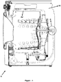
- the household appliance (A) may be a washing machine as exemplified in Figure 1 .
- the chamber (A2) is a drum and is rotatable around an axis parallel to the ground on which the household appliance (A) is provided.
- the chamber (A2) is also connected to the body (A1) of the household appliance (A) at a rear part thereof so that it can rotate on said axis.
- the rotary joint (D) is used while realizing said connection, wherein the rotary joint (D) is connected to a fluid source from the first inlet (1a), preferably via a transmission element such as a hose, and the first outlet (1b) of the rotary joint (D) is connected to another transmission line (e.g. to the drum shaft) which transfers fluid (e.g. washing liquid) into the chamber (A1).
- fluid from the source enters the fluid passage (1c) through the first inlet (1a) and passes therefrom to the channel in the shaft (4).
- the fluid moving through the channel exits through the first outlet (1b) and passes to the transmission line which transfers the fluid into the chamber (A2).
- the shaft (4) comprises at least one shaft body (4a) preferably having a cylindrical form, connected on a first side to the fluid passage (1c), and at which the channel is provided; and at least one connection portion (4b) for connecting the shaft (4) and hence the rotary joint (D) to said chamber (A) and which is located on a second side of the shaft body (4a) opposite to the first side thereof. Therefore, the rotary joint (D) can be easily connected to the chamber (A2).
- the connection portion (4b) is preferably in the form of a nut.
- the rotary joint (D) preferably comprises at least one directing element (5) which is located at the elbow part of the fluid passage (1c) in the main body (1), wherein an upper corner of the directing element (5) facing the first inlet (1a) is curved, and wherein the fluid coming from the first inlet (1a) to the fluid passage (1c) passes through the directing element (5) and is directed into the channel in the shaft (4). Thanks to the directing element (5), a possible pressure decrease can be prevented by softening the 90-degree fluid orientation in the fluid passage (1c) of the main body (1) (especially in the elbow part of the "L" form).
- the directing element (5) preferably comprises at least a second inlet (5a) through which fluid coming from the first inlet (1a) into the fluid passage (1c) enters into the directing element (5); and at least a second outlet (5b) through which fluid in the directing element (5) is directed into the channel in the shaft (4) and which is attached to the channel (preferably located in the channel).
- the shaft (4) preferably comprises at least one connection slot formed as a recess from the inner surface of the shaft (4) towards the outer surface thereof.
- the directing element (5) preferably comprises at least one connection member which is preferably in the form of a protrusion and located at the elbow part of the "L" form of the fluid passage (1c), thus enabling the directing element (5) to be located in the main body (1) in a more stable and immobile way.
- the rotary joint (D) according to this embodiment also preferably comprises at least one connection element (6) which is preferably in the form of a screw and enables the directing element (5) to be fixed in the main body (1).
- the rotary joint (D) according to the invention preferably comprises at least a first holding slot which is located at the placement compartment (1d), formed as a recess from the inner surface of the main body (1) towards the outer surface thereof, and in which the sealing element (2) is placed.
- the rotary joint (D) according to the invention also preferably comprises at least a second holding slot which is located at the placement compartment (1d), formed as a recess from the inner surface of the main body (1) towards the outer surface thereof, and in which the bearing (3) is placed.
- the second holding slot and the first holding slot are located side by side to form a step.
- the rotary joint (D) in household appliances (A) having a chamber (A2) rotatably mounted in the body (A1), fluid transfer into the chamber (A2) can be enabled in a way that rotational movement of the chamber (A2) is not prevented.
- simple structure of the rotary joint (D) decreases both labour and production costs, as well as achieving a long-lasting and reliable rotary joint (D) by minimizing the risk of malfunction.
Landscapes
- Engineering & Computer Science (AREA)
- Textile Engineering (AREA)
- Joints Allowing Movement (AREA)
Abstract
Description
- The present invention relates to rotary joints enabling fluid intake into chambers, which are rotatably mounted in a body, such that the rotary joints do not prevent such rotational movement of the chamber.
- Especially, household appliances that have a chamber capable of performing rotational movement in a body, such as washing and/or drying devices, are widely used today in order to facilitate daily work, increase efficiency, minimize time loss and save energy. In such household appliances, a fluid such as a washing liquid or drying air may be required to be supplied into the chamber in order for the household appliance to perform its function. However, since the chamber is connected to the body in a rotatable manner, such a supplying process should be performed both in a sealed manner and in such a way that other components are prevented from being damaged as a result of the rotational movement.
- In particular, these chambers rotatable around a horizontal axis are connected to the body at a rear side thereof, from where water supply into the chamber is carried out. An example of said application is disclosed in the patent application
US2005092032A1 , wherein the chamber described as a drum is connected to the body by means of a rotary joint. However, in the application disclosed in this document, since quite complex structures are used to supply the fluid, labour and production costs increase accordingly. Furthermore, using complex structures increases the risk of malfunction and increases service costs that may occur afterwards. - In addition, double bearing and axial seals are used in rotary joint applications in the known art, which leads to an increase in production costs. Further, pressure loss occurs in the water supply due to the structure of rotary joints. This may lead to a decrease in efficiency of the household appliances, especially the ones using water jet, and decrease in the working performance of the household appliance.
- The rotary joint according to the present invention which, in household appliances having at least one body and at least one chamber mounted in the body rotatable around an axis, enables a fluid received from a source to be supplied into the chamber comprises:
- at least one main body having at least a first inlet through which fluid from the source passes and at least a first outlet through which fluid received from the first inlet exits;
- at least one placement compartment provided at the main body, wherein the first outlet is located at the placement compartment;
- at least one fluid passage which is located in the main body, has an "L" form, connected on one side to the first inlet and on another side to the placement compartment, and directs the fluid received from the first inlet towards the first outlet;
- at least one sealing element located at the placement compartment to fit in an inner surface of the placement compartment, the sealing element having at least a first hole through which fluid from the fluid passage can pass;
- at least one bearing which is located at the placement compartment such that it fits in an inner surface of the placement compartment and the sealing element remains between the bearing and the fluid passage, the bearing having at least a second hole through which fluid from the fluid passage can pass; and
- at least one shaft inserted through the first hole and the second hole into the placement compartment and having therein at least one channel through which fluid from the fluid passage passes, wherein one end of the shaft is connected to the fluid passage and another opposite end thereof is connected to the first outlet.
- Thanks to the rotary joint according to the present invention, in household appliances having a chamber rotatably mounted in the body, fluid transfer into the chamber can be enabled in a way that rotational movement of the chamber is not prevented. In addition, simple structure of the rotary joint decreases both labour and production costs, as well as achieving a long-lasting and reliable rotary joint by minimizing the risk of malfunction.
- An object of the present invention is to provide a rotary joint enabling fluid intake into chambers, which are rotatably mounted in a body, such the rotary joint does not prevent such rotational movement of the chamber.
- Another object of the present invention is to provide a rotary joint by which both labour and production costs are decreased.
- A further object of the present invention is to provide a rotary joint suitable for use in household appliances especially having a water jet application.
- Yet another object of the present invention is to provide a rotary joint minimizing pressure decrease that may occur during fluid supply.
- Exemplary embodiments of the rotary joint according to the present invention are illustrated in the attached drawings, in which:
-
Figure 1 is a sectional view of a use of the developed rotary joint in a household appliance that is exemplified as a washing machine. -
Figure 2 is a perspective view of the developed rotary joint. -
Figure 3 is a perspective view of the developed rotary joint in a disassembled state. -
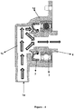
Figure 4 is a side-sectional view of an embodiment of the developed rotary joint. -
Figure 5 is a side-sectional view of another embodiment of the developed rotary joint. - All the parts illustrated in figures are individually assigned a reference numeral and the corresponding terms of these numbers are listed below:
Household appliance (A) Body (A1) Chamber (A2) Rotary joint (D) Main body (1) First inlet (1a) First outlet (1b) Fluid passage (1c) Placement compartment (1d) Sealing element (2) Bearing (3) Shaft (4) Shaft body (4a) Connection portion (4b) Directing element (5) Second inlet (5a) Second outlet (5b) Connection member (5c) Connection element (6) - Household appliances such as washing and/or drying devices have a body and a chamber mounted in the body rotatable around an axis. A fluid such as a washing liquid or drying air is supplied into the chamber so that a respective function (e.g. washing, drying) of the household appliance is carried out in the chamber. Said fluid supply is generally performed at the part where the chamber is connected to the body. However, it is necessary to prevent rotation of the chamber from adversely affecting this fluid supplying process (for example, preventing the components which perform the supplying process from deforming, not preventing rotation of the chamber, etc.), and for this purpose, in the known art, the chamber is enabled to be connected to the body by using parts called rotary joints. However, rotary joint applications in the known art may include complex connection structures or the known rotary joints may comprise too many components in terms of their structural properties. This can lead to an increase in production and labour costs as well as an increase in the probability of malfunction. In addition, said applications may lead to a pressure loss especially in household appliances having a water jet application, in which case the working performance of household appliances may decrease. Accordingly, with the present invention, there is provided a rotary joint for solving said problems.
- The rotary joint (D) according to the present invention, as illustrated in
figures 1-5 , which, in household appliances (A) (e.g. washing and/or drying device) having at least one body (A1) and at least one chamber (A2) (e.g. a drum) mounted in the body (A1) rotatable around an axis preferably extending in the horizontal axis, enables a fluid received from a source (e.g. from the mains or for example from the chamber (A2) by means of a pump for recirculating the fluid) to be supplied into the chamber (A2) comprises: at least one main body (1) having at least a first inlet (1a) through which fluid from the source passes and at least a first outlet (1b) through which fluid received from the first inlet (1a) exits (e.g. is directed into the chamber (A2)). The rotary joint (D) also comprises at least one placement compartment (1d) preferably having a circular section and provided at the main body (1), wherein the first outlet (1b) is located at the placement compartment (1d); at least one fluid passage (1c) which is located in the main body (1), has an "L" form, connected on one side to the first inlet (1a) and on another side to the placement compartment (1d), and directs the fluid received from the first inlet (1a) towards the first outlet (1b); at least one sealing element (2) (e.g. a radial felt) preferably having a circular section and located at the placement compartment (1d) to fit in an inner surface of the placement compartment (1d), the sealing element (2) having at least a first hole through which fluid from the fluid passage (1c) can pass; at least one bearing (3) (preferably, a ball bearing) which is located at the placement compartment (1d) such that it fits in an inner surface of the placement compartment (1d) and the sealing element (2) remains between the bearing (3) and the fluid passage (1c), the bearing (3) having at least a second hole through which fluid from the fluid passage (1c) can pass; and at least one shaft (4) preferably having a cylindrical form, inserted through the first hole and the second hole into the placement compartment (1d) and having therein at least one channel through which fluid from the fluid passage (1c) passes, wherein one end of the shaft (4) is connected to the fluid passage (1c) and another opposite end thereof is connected to the first outlet (1b) (preferably, extending outwards from the first outlet (1b)). - In an exemplary embodiment of the invention, the household appliance (A) may be a washing machine as exemplified in
Figure 1 . In this case, the chamber (A2) is a drum and is rotatable around an axis parallel to the ground on which the household appliance (A) is provided. The chamber (A2) is also connected to the body (A1) of the household appliance (A) at a rear part thereof so that it can rotate on said axis. The rotary joint (D) according to the present invention is used while realizing said connection, wherein the rotary joint (D) is connected to a fluid source from the first inlet (1a), preferably via a transmission element such as a hose, and the first outlet (1b) of the rotary joint (D) is connected to another transmission line (e.g. to the drum shaft) which transfers fluid (e.g. washing liquid) into the chamber (A1). As exemplified inFigure 4 , fluid from the source enters the fluid passage (1c) through the first inlet (1a) and passes therefrom to the channel in the shaft (4). The fluid moving through the channel exits through the first outlet (1b) and passes to the transmission line which transfers the fluid into the chamber (A2). Thanks to the bearing (3) of the rotary joint (D) according to the invention, rotation of the chamber (A2) is not prevented while the fluid is transferred from the source into the chamber (A2). Moreover, thanks to the sealing element (2) between the bearing (3) and the fluid passage (1c) and due to the fact that the shaft (4) is located at the placement opening (1d) by passing through the first hole and the second hole, fluid in the main body (1) can be prevented from leaking out the main body (1) and/or shaft (4) until the fluid is transferred into the chamber (A2). Therefore, both the other components of the household appliance (A) outside the main body (1) and the bearing (3) in the rotary joint (D) can be protected from the fluid, and a long-lasting rotary joint (D) can be achieved by minimizing the corrosion that may occur because of the fluid. Further, thanks to the simple structure of the rotary joint (D), both labour and production costs are decreased and the risk of malfunction can be minimized. - In a preferred embodiment of the invention, the shaft (4) comprises at least one shaft body (4a) preferably having a cylindrical form, connected on a first side to the fluid passage (1c), and at which the channel is provided; and at least one connection portion (4b) for connecting the shaft (4) and hence the rotary joint (D) to said chamber (A) and which is located on a second side of the shaft body (4a) opposite to the first side thereof. Therefore, the rotary joint (D) can be easily connected to the chamber (A2). The connection portion (4b) is preferably in the form of a nut.
- In another alternative embodiment illustrated in
Figure 3 andFigure 5 , the rotary joint (D) according to the invention preferably comprises at least one directing element (5) which is located at the elbow part of the fluid passage (1c) in the main body (1), wherein an upper corner of the directing element (5) facing the first inlet (1a) is curved, and wherein the fluid coming from the first inlet (1a) to the fluid passage (1c) passes through the directing element (5) and is directed into the channel in the shaft (4). Thanks to the directing element (5), a possible pressure decrease can be prevented by softening the 90-degree fluid orientation in the fluid passage (1c) of the main body (1) (especially in the elbow part of the "L" form). The directing element (5) preferably comprises at least a second inlet (5a) through which fluid coming from the first inlet (1a) into the fluid passage (1c) enters into the directing element (5); and at least a second outlet (5b) through which fluid in the directing element (5) is directed into the channel in the shaft (4) and which is attached to the channel (preferably located in the channel). In the part where the second outlet (5b) is attached to the channel, the shaft (4) preferably comprises at least one connection slot formed as a recess from the inner surface of the shaft (4) towards the outer surface thereof. Thus, a smoother fluid passage with minimized leakage possibility can be achieved by preventing a height difference between the channel in the shaft (4) and the second outlet (5b). Also, in this way, the pressure to which the sealing member (2) is subjected due to the fluid can be reduced. The directing element (5) preferably comprises at least one connection member which is preferably in the form of a protrusion and located at the elbow part of the "L" form of the fluid passage (1c), thus enabling the directing element (5) to be located in the main body (1) in a more stable and immobile way. The rotary joint (D) according to this embodiment also preferably comprises at least one connection element (6) which is preferably in the form of a screw and enables the directing element (5) to be fixed in the main body (1). - In another exemplary embodiment, the rotary joint (D) according to the invention preferably comprises at least a first holding slot which is located at the placement compartment (1d), formed as a recess from the inner surface of the main body (1) towards the outer surface thereof, and in which the sealing element (2) is placed. The rotary joint (D) according to the invention also preferably comprises at least a second holding slot which is located at the placement compartment (1d), formed as a recess from the inner surface of the main body (1) towards the outer surface thereof, and in which the bearing (3) is placed. In this embodiment, preferably, the second holding slot and the first holding slot are located side by side to form a step.
- Thanks to the rotary joint (D) according to the present invention, in household appliances (A) having a chamber (A2) rotatably mounted in the body (A1), fluid transfer into the chamber (A2) can be enabled in a way that rotational movement of the chamber (A2) is not prevented. In addition, simple structure of the rotary joint (D) decreases both labour and production costs, as well as achieving a long-lasting and reliable rotary joint (D) by minimizing the risk of malfunction.
Claims (15)
- A rotary joint (D) which, in household appliances (A) having at least one body (A1) and at least one chamber (A2) mounted in the body (A1) rotatable around an axis, enables a fluid received from a source to be supplied into the chamber (A2) and comprises at least one main body (1) having at least a first inlet (1a) through which fluid from the source passes and at least a first outlet (1b) through which fluid received from the first inlet (1a) exits, the rotary joint (D) characterized by comprising:- at least one placement compartment (1d) provided at the main body (1), wherein the first outlet (1b) is located at the placement compartment (1d);- at least one fluid passage (1c) which is located in the main body (1), has an "L" form, connected on one side to the first inlet (1a) and on another side to the placement compartment (1d), and directs the fluid received from the first inlet (1a) towards the first outlet (1b);- at least one sealing element (2) located at the placement compartment (1d) to fit in an inner surface of the placement compartment (1d), the sealing element (2) having at least a first hole through which fluid from the fluid passage (1c) can pass;- at least one bearing (3) which is located at the placement compartment (1d) such that it fits in an inner surface of the placement compartment (1d) and the sealing element (2) remains between the bearing (3) and the fluid passage (1c), the bearing (3) having at least a second hole through which fluid from the fluid passage (1c) can pass; and- at least one shaft (4) inserted through the first hole and the second hole into the placement compartment (1d) and having therein at least one channel through which fluid from the fluid passage (1c) passes, wherein one end of the shaft (4) is connected to the fluid passage (1c) and another opposite end thereof is connected to the first outlet (1b).
- A rotary joint (D) according to claim 1, characterized in that the sealing element (2) is a radial felt.
- A rotary joint (D) according to claim 1, characterized in that the bearing (3) is a ball bearing.
- A rotary joint (D) according to claim 1, characterized in that the shaft (4) comprises at least one shaft body (4a) connected on a first side to the fluid passage (1c) and at which the channel is provided; and at least one connection portion (4b) for connecting the shaft (4) and hence the rotary joint (D) to said chamber (A) and which is located on a second side of the shaft body (4a) opposite to the first side thereof.
- A rotary joint (D) according to claim 4, characterized in that the connection portion (4b) is in the form of a nut.
- A rotary joint (D) according to any of the preceding claims, characterized by comprising at least one directing element (5) which is located at the elbow part of the fluid passage (1c) in the main body (1), wherein an upper corner of the directing element (5) facing the first inlet (1a) is curved, and wherein the fluid coming from the first inlet (1a) to the fluid passage (1c) passes through the directing element (5) and is directed into the channel in the shaft (4).
- A rotary joint (D) according to claim 6, characterized in that the directing element (5) comprises at least a second inlet (5a) through which fluid coming from the first inlet (1a) into the fluid passage (1c) enters into the directing element (5); and at least a second outlet (5b) through which fluid in the directing element (5) is directed into the channel in the shaft (4) and which is attached to the channel.
- A rotary joint (D) according to claim 7, characterized in that the shaft (4) comprises at least one connection slot formed as a recess from the inner surface of the shaft (4) towards the outer surface thereof in the part where the second outlet (5b) is attached to the channel.
- A rotary joint (D) according to claims 6 to 8, characterized in that the directing element (5) comprises at least one connection member (5c) which is located at the elbow part of the "L" form of the fluid passage (1c).
- A rotary joint (D) according to claims 6 to 9, characterized by comprising at least one connection element (6) which enables the directing element (5) to be fixed in the main body (1).
- A rotary joint (D) according to any of the preceding claims, characterized by comprising at least a first holding slot which is located at the placement compartment (1d), formed as a recess from the inner surface of the main body (1) towards the outer surface thereof, and in which the sealing element (2) is placed.
- A rotary joint (D) according to any of the preceding claims, characterized by comprising at least a second holding slot which is located at the placement compartment (1d), formed as a recess from the inner surface of the main body (1) towards the outer surface thereof, and in which the bearing (3) is placed.
- A rotary joint (D) according to claim 12, characterized in that the second holding slot and the first holding slot are located side by side to form a step.
- A rotary joint (D) according to any of the preceding claims, characterized in that the source is mains.
- A rotary joint (D) according to any of the preceding claims, characterized in that the source is the chamber (A2) in which the fluid therein is recirculated by means of a pump.
Applications Claiming Priority (1)
| Application Number | Priority Date | Filing Date | Title |
|---|---|---|---|
| TR2019/18205A TR201918205A2 (en) | 2019-11-21 | 2019-11-21 | A swivel joint for white goods. |
Publications (2)
| Publication Number | Publication Date |
|---|---|
| EP3825453A1 true EP3825453A1 (en) | 2021-05-26 |
| EP3825453B1 EP3825453B1 (en) | 2022-09-14 |
Family
ID=73598662
Family Applications (1)
| Application Number | Title | Priority Date | Filing Date |
|---|---|---|---|
| EP20207237.7A Active EP3825453B1 (en) | 2019-11-21 | 2020-11-12 | A rotary joint for white appliances |
Country Status (2)
| Country | Link |
|---|---|
| EP (1) | EP3825453B1 (en) |
| TR (1) | TR201918205A2 (en) |
Families Citing this family (1)
| Publication number | Priority date | Publication date | Assignee | Title |
|---|---|---|---|---|
| CN114606730B (en) * | 2020-12-09 | 2025-08-26 | 青岛海尔洗涤电器有限公司 | Drum water inlet structure and drum washing machine |
Citations (5)
| Publication number | Priority date | Publication date | Assignee | Title |
|---|---|---|---|---|
| GB647439A (en) * | 1948-03-10 | 1950-12-13 | Achille Serre Ltd | Improvements in washing machines |
| WO1999034051A1 (en) * | 1997-12-24 | 1999-07-08 | Alliance Laundry Systems Llc | Dry-cleaning machine with controlled agitation |
| US20050092032A1 (en) | 1999-03-25 | 2005-05-05 | North John H. | Washing and drying machines and dry-cleaning machines |
| EP2896738A1 (en) * | 2013-12-20 | 2015-07-22 | Dongbu Daewoo Electronics Corporation | Washing machine with integrated tub/drum |
| WO2018205934A1 (en) * | 2017-05-09 | 2018-11-15 | 青岛海尔滚筒洗衣机有限公司 | Drum washing machine |
-
2019
- 2019-11-21 TR TR2019/18205A patent/TR201918205A2/en unknown
-
2020
- 2020-11-12 EP EP20207237.7A patent/EP3825453B1/en active Active
Patent Citations (5)
| Publication number | Priority date | Publication date | Assignee | Title |
|---|---|---|---|---|
| GB647439A (en) * | 1948-03-10 | 1950-12-13 | Achille Serre Ltd | Improvements in washing machines |
| WO1999034051A1 (en) * | 1997-12-24 | 1999-07-08 | Alliance Laundry Systems Llc | Dry-cleaning machine with controlled agitation |
| US20050092032A1 (en) | 1999-03-25 | 2005-05-05 | North John H. | Washing and drying machines and dry-cleaning machines |
| EP2896738A1 (en) * | 2013-12-20 | 2015-07-22 | Dongbu Daewoo Electronics Corporation | Washing machine with integrated tub/drum |
| WO2018205934A1 (en) * | 2017-05-09 | 2018-11-15 | 青岛海尔滚筒洗衣机有限公司 | Drum washing machine |
Also Published As
| Publication number | Publication date |
|---|---|
| EP3825453B1 (en) | 2022-09-14 |
| TR201918205A2 (en) | 2021-06-21 |
Similar Documents
| Publication | Publication Date | Title |
|---|---|---|
| US8926275B2 (en) | Centrifugal pump | |
| EP3825453A1 (en) | A rotary joint for white appliances | |
| CN105986432A (en) | A drum type washing machine | |
| KR20230091044A (en) | Screw Spindle Pump | |
| US11377774B2 (en) | Drum washing machine, and spraying system and sealed window pad thereof | |
| CN114318798A (en) | Gas clothes dryer with double clothes drying rollers | |
| WO2019237932A1 (en) | Drum-type washing machine and spray device thereof | |
| CN209307689U (en) | Rotary drum washing machine and its spray system and outer bung | |
| WO2019201116A1 (en) | Front-loading washer and spray system thereof | |
| JPH1151067A (en) | Machine equipped with rotor having bearing and liquid lubrication bearing | |
| CN221220791U (en) | Electronic water pump structure and water jet loom | |
| CN110607664A (en) | Drum washing machine and its spray system and drive shaft assembly | |
| WO2019237948A1 (en) | Front-loading washing machine and spraying system and sealing window gasket thereof | |
| CN114687158B (en) | Spray system and clothes treatment equipment | |
| KR100896814B1 (en) | Cleaning Injector | |
| WO2019237947A1 (en) | Front-loading washing machine and nozzle of washing machine | |
| CN110387700A (en) | Roller washing machine and its spray system | |
| CN110607644A (en) | Drum washing machine and its inner drum assembly | |
| CN217536416U (en) | Water inlet valve mounting structure and clothes treatment equipment | |
| CN118147864B (en) | Wall-mounted clothes treating apparatus | |
| CN116163105A (en) | Clothes washing device | |
| KR200300795Y1 (en) | a water sprayer for dishwasher | |
| CN210089359U (en) | Automatic doffer of bipyramid drying equipment | |
| CN106965208B (en) | Self-drainage mechanical arm | |
| CN110607655B (en) | Front-loading washing machine and its inner drum assembly |
Legal Events
| Date | Code | Title | Description |
|---|---|---|---|
| PUAI | Public reference made under article 153(3) epc to a published international application that has entered the european phase |
Free format text: ORIGINAL CODE: 0009012 |
|
| STAA | Information on the status of an ep patent application or granted ep patent |
Free format text: STATUS: THE APPLICATION HAS BEEN PUBLISHED |
|
| AK | Designated contracting states |
Kind code of ref document: A1 Designated state(s): AL AT BE BG CH CY CZ DE DK EE ES FI FR GB GR HR HU IE IS IT LI LT LU LV MC MK MT NL NO PL PT RO RS SE SI SK SM TR |
|
| STAA | Information on the status of an ep patent application or granted ep patent |
Free format text: STATUS: REQUEST FOR EXAMINATION WAS MADE |
|
| 17P | Request for examination filed |
Effective date: 20211122 |
|
| RBV | Designated contracting states (corrected) |
Designated state(s): AL AT BE BG CH CY CZ DE DK EE ES FI FR GB GR HR HU IE IS IT LI LT LU LV MC MK MT NL NO PL PT RO RS SE SI SK SM TR |
|
| GRAP | Despatch of communication of intention to grant a patent |
Free format text: ORIGINAL CODE: EPIDOSNIGR1 |
|
| STAA | Information on the status of an ep patent application or granted ep patent |
Free format text: STATUS: GRANT OF PATENT IS INTENDED |
|
| INTG | Intention to grant announced |
Effective date: 20220426 |
|
| GRAS | Grant fee paid |
Free format text: ORIGINAL CODE: EPIDOSNIGR3 |
|
| GRAA | (expected) grant |
Free format text: ORIGINAL CODE: 0009210 |
|
| STAA | Information on the status of an ep patent application or granted ep patent |
Free format text: STATUS: THE PATENT HAS BEEN GRANTED |
|
| AK | Designated contracting states |
Kind code of ref document: B1 Designated state(s): AL AT BE BG CH CY CZ DE DK EE ES FI FR GB GR HR HU IE IS IT LI LT LU LV MC MK MT NL NO PL PT RO RS SE SI SK SM TR |
|
| REG | Reference to a national code |
Ref country code: GB Ref legal event code: FG4D |
|
| REG | Reference to a national code |
Ref country code: CH Ref legal event code: EP |
|
| REG | Reference to a national code |
Ref country code: DE Ref legal event code: R096 Ref document number: 602020005119 Country of ref document: DE |
|
| REG | Reference to a national code |
Ref country code: IE Ref legal event code: FG4D |
|
| REG | Reference to a national code |
Ref country code: AT Ref legal event code: REF Ref document number: 1518756 Country of ref document: AT Kind code of ref document: T Effective date: 20221015 |
|
| REG | Reference to a national code |
Ref country code: LT Ref legal event code: MG9D |
|
| REG | Reference to a national code |
Ref country code: NL Ref legal event code: MP Effective date: 20220914 |
|
| PG25 | Lapsed in a contracting state [announced via postgrant information from national office to epo] |
Ref country code: SE Free format text: LAPSE BECAUSE OF FAILURE TO SUBMIT A TRANSLATION OF THE DESCRIPTION OR TO PAY THE FEE WITHIN THE PRESCRIBED TIME-LIMIT Effective date: 20220914 Ref country code: RS Free format text: LAPSE BECAUSE OF FAILURE TO SUBMIT A TRANSLATION OF THE DESCRIPTION OR TO PAY THE FEE WITHIN THE PRESCRIBED TIME-LIMIT Effective date: 20220914 Ref country code: NO Free format text: LAPSE BECAUSE OF FAILURE TO SUBMIT A TRANSLATION OF THE DESCRIPTION OR TO PAY THE FEE WITHIN THE PRESCRIBED TIME-LIMIT Effective date: 20221214 Ref country code: LV Free format text: LAPSE BECAUSE OF FAILURE TO SUBMIT A TRANSLATION OF THE DESCRIPTION OR TO PAY THE FEE WITHIN THE PRESCRIBED TIME-LIMIT Effective date: 20220914 Ref country code: LT Free format text: LAPSE BECAUSE OF FAILURE TO SUBMIT A TRANSLATION OF THE DESCRIPTION OR TO PAY THE FEE WITHIN THE PRESCRIBED TIME-LIMIT Effective date: 20220914 Ref country code: FI Free format text: LAPSE BECAUSE OF FAILURE TO SUBMIT A TRANSLATION OF THE DESCRIPTION OR TO PAY THE FEE WITHIN THE PRESCRIBED TIME-LIMIT Effective date: 20220914 |
|
| REG | Reference to a national code |
Ref country code: AT Ref legal event code: MK05 Ref document number: 1518756 Country of ref document: AT Kind code of ref document: T Effective date: 20220914 |
|
| PG25 | Lapsed in a contracting state [announced via postgrant information from national office to epo] |
Ref country code: HR Free format text: LAPSE BECAUSE OF FAILURE TO SUBMIT A TRANSLATION OF THE DESCRIPTION OR TO PAY THE FEE WITHIN THE PRESCRIBED TIME-LIMIT Effective date: 20220914 Ref country code: GR Free format text: LAPSE BECAUSE OF FAILURE TO SUBMIT A TRANSLATION OF THE DESCRIPTION OR TO PAY THE FEE WITHIN THE PRESCRIBED TIME-LIMIT Effective date: 20221215 |
|
| PG25 | Lapsed in a contracting state [announced via postgrant information from national office to epo] |
Ref country code: SM Free format text: LAPSE BECAUSE OF FAILURE TO SUBMIT A TRANSLATION OF THE DESCRIPTION OR TO PAY THE FEE WITHIN THE PRESCRIBED TIME-LIMIT Effective date: 20220914 Ref country code: RO Free format text: LAPSE BECAUSE OF FAILURE TO SUBMIT A TRANSLATION OF THE DESCRIPTION OR TO PAY THE FEE WITHIN THE PRESCRIBED TIME-LIMIT Effective date: 20220914 Ref country code: PT Free format text: LAPSE BECAUSE OF FAILURE TO SUBMIT A TRANSLATION OF THE DESCRIPTION OR TO PAY THE FEE WITHIN THE PRESCRIBED TIME-LIMIT Effective date: 20230116 Ref country code: ES Free format text: LAPSE BECAUSE OF FAILURE TO SUBMIT A TRANSLATION OF THE DESCRIPTION OR TO PAY THE FEE WITHIN THE PRESCRIBED TIME-LIMIT Effective date: 20220914 Ref country code: CZ Free format text: LAPSE BECAUSE OF FAILURE TO SUBMIT A TRANSLATION OF THE DESCRIPTION OR TO PAY THE FEE WITHIN THE PRESCRIBED TIME-LIMIT Effective date: 20220914 Ref country code: AT Free format text: LAPSE BECAUSE OF FAILURE TO SUBMIT A TRANSLATION OF THE DESCRIPTION OR TO PAY THE FEE WITHIN THE PRESCRIBED TIME-LIMIT Effective date: 20220914 |
|
| PG25 | Lapsed in a contracting state [announced via postgrant information from national office to epo] |
Ref country code: SK Free format text: LAPSE BECAUSE OF FAILURE TO SUBMIT A TRANSLATION OF THE DESCRIPTION OR TO PAY THE FEE WITHIN THE PRESCRIBED TIME-LIMIT Effective date: 20220914 Ref country code: PL Free format text: LAPSE BECAUSE OF FAILURE TO SUBMIT A TRANSLATION OF THE DESCRIPTION OR TO PAY THE FEE WITHIN THE PRESCRIBED TIME-LIMIT Effective date: 20220914 Ref country code: IS Free format text: LAPSE BECAUSE OF FAILURE TO SUBMIT A TRANSLATION OF THE DESCRIPTION OR TO PAY THE FEE WITHIN THE PRESCRIBED TIME-LIMIT Effective date: 20230114 Ref country code: EE Free format text: LAPSE BECAUSE OF FAILURE TO SUBMIT A TRANSLATION OF THE DESCRIPTION OR TO PAY THE FEE WITHIN THE PRESCRIBED TIME-LIMIT Effective date: 20220914 |
|
| REG | Reference to a national code |
Ref country code: DE Ref legal event code: R097 Ref document number: 602020005119 Country of ref document: DE |
|
| PG25 | Lapsed in a contracting state [announced via postgrant information from national office to epo] |
Ref country code: NL Free format text: LAPSE BECAUSE OF FAILURE TO SUBMIT A TRANSLATION OF THE DESCRIPTION OR TO PAY THE FEE WITHIN THE PRESCRIBED TIME-LIMIT Effective date: 20220914 Ref country code: MC Free format text: LAPSE BECAUSE OF FAILURE TO SUBMIT A TRANSLATION OF THE DESCRIPTION OR TO PAY THE FEE WITHIN THE PRESCRIBED TIME-LIMIT Effective date: 20220914 Ref country code: AL Free format text: LAPSE BECAUSE OF FAILURE TO SUBMIT A TRANSLATION OF THE DESCRIPTION OR TO PAY THE FEE WITHIN THE PRESCRIBED TIME-LIMIT Effective date: 20220914 |
|
| PLBE | No opposition filed within time limit |
Free format text: ORIGINAL CODE: 0009261 |
|
| STAA | Information on the status of an ep patent application or granted ep patent |
Free format text: STATUS: NO OPPOSITION FILED WITHIN TIME LIMIT |
|
| REG | Reference to a national code |
Ref country code: BE Ref legal event code: MM Effective date: 20221130 |
|
| PG25 | Lapsed in a contracting state [announced via postgrant information from national office to epo] |
Ref country code: DK Free format text: LAPSE BECAUSE OF FAILURE TO SUBMIT A TRANSLATION OF THE DESCRIPTION OR TO PAY THE FEE WITHIN THE PRESCRIBED TIME-LIMIT Effective date: 20220914 |
|
| 26N | No opposition filed |
Effective date: 20230615 |
|
| PG25 | Lapsed in a contracting state [announced via postgrant information from national office to epo] |
Ref country code: SI Free format text: LAPSE BECAUSE OF FAILURE TO SUBMIT A TRANSLATION OF THE DESCRIPTION OR TO PAY THE FEE WITHIN THE PRESCRIBED TIME-LIMIT Effective date: 20220914 Ref country code: LU Free format text: LAPSE BECAUSE OF NON-PAYMENT OF DUE FEES Effective date: 20221112 |
|
| PG25 | Lapsed in a contracting state [announced via postgrant information from national office to epo] |
Ref country code: IE Free format text: LAPSE BECAUSE OF NON-PAYMENT OF DUE FEES Effective date: 20221112 |
|
| PG25 | Lapsed in a contracting state [announced via postgrant information from national office to epo] |
Ref country code: BE Free format text: LAPSE BECAUSE OF NON-PAYMENT OF DUE FEES Effective date: 20221130 |
|
| PG25 | Lapsed in a contracting state [announced via postgrant information from national office to epo] |
Ref country code: CY Free format text: LAPSE BECAUSE OF FAILURE TO SUBMIT A TRANSLATION OF THE DESCRIPTION OR TO PAY THE FEE WITHIN THE PRESCRIBED TIME-LIMIT Effective date: 20220914 |
|
| PG25 | Lapsed in a contracting state [announced via postgrant information from national office to epo] |
Ref country code: MK Free format text: LAPSE BECAUSE OF FAILURE TO SUBMIT A TRANSLATION OF THE DESCRIPTION OR TO PAY THE FEE WITHIN THE PRESCRIBED TIME-LIMIT Effective date: 20220914 |
|
| REG | Reference to a national code |
Ref country code: CH Ref legal event code: PL |
|
| PG25 | Lapsed in a contracting state [announced via postgrant information from national office to epo] |
Ref country code: CH Free format text: LAPSE BECAUSE OF NON-PAYMENT OF DUE FEES Effective date: 20231130 |
|
| PG25 | Lapsed in a contracting state [announced via postgrant information from national office to epo] |
Ref country code: HU Free format text: LAPSE BECAUSE OF FAILURE TO SUBMIT A TRANSLATION OF THE DESCRIPTION OR TO PAY THE FEE WITHIN THE PRESCRIBED TIME-LIMIT; INVALID AB INITIO Effective date: 20201112 Ref country code: CH Free format text: LAPSE BECAUSE OF NON-PAYMENT OF DUE FEES Effective date: 20231130 Ref country code: BG Free format text: LAPSE BECAUSE OF FAILURE TO SUBMIT A TRANSLATION OF THE DESCRIPTION OR TO PAY THE FEE WITHIN THE PRESCRIBED TIME-LIMIT Effective date: 20220914 |
|
| PG25 | Lapsed in a contracting state [announced via postgrant information from national office to epo] |
Ref country code: MT Free format text: LAPSE BECAUSE OF FAILURE TO SUBMIT A TRANSLATION OF THE DESCRIPTION OR TO PAY THE FEE WITHIN THE PRESCRIBED TIME-LIMIT Effective date: 20220914 |
|
| PGFP | Annual fee paid to national office [announced via postgrant information from national office to epo] |
Ref country code: TR Payment date: 20241111 Year of fee payment: 5 |
|
| PGFP | Annual fee paid to national office [announced via postgrant information from national office to epo] |
Ref country code: DE Payment date: 20251119 Year of fee payment: 6 |
|
| PGFP | Annual fee paid to national office [announced via postgrant information from national office to epo] |
Ref country code: GB Payment date: 20251121 Year of fee payment: 6 |
|
| PGFP | Annual fee paid to national office [announced via postgrant information from national office to epo] |
Ref country code: IT Payment date: 20251125 Year of fee payment: 6 |
|
| PGFP | Annual fee paid to national office [announced via postgrant information from national office to epo] |
Ref country code: FR Payment date: 20251126 Year of fee payment: 6 |