EP3825270A1 - Method for operating an elevator and elevator - Google Patents
Method for operating an elevator and elevator Download PDFInfo
- Publication number
- EP3825270A1 EP3825270A1 EP19210803.3A EP19210803A EP3825270A1 EP 3825270 A1 EP3825270 A1 EP 3825270A1 EP 19210803 A EP19210803 A EP 19210803A EP 3825270 A1 EP3825270 A1 EP 3825270A1
- Authority
- EP
- European Patent Office
- Prior art keywords
- elevator
- motor
- characteristic
- stator
- movable unit
- Prior art date
- Legal status (The legal status is an assumption and is not a legal conclusion. Google has not performed a legal analysis and makes no representation as to the accuracy of the status listed.)
- Granted
Links
Images

Classifications
-
- B—PERFORMING OPERATIONS; TRANSPORTING
- B66—HOISTING; LIFTING; HAULING
- B66B—ELEVATORS; ESCALATORS OR MOVING WALKWAYS
- B66B1/00—Control systems of elevators in general
- B66B1/34—Details, e.g. call counting devices, data transmission from car to control system, devices giving information to the control system
- B66B1/3407—Setting or modification of parameters of the control system
-
- B—PERFORMING OPERATIONS; TRANSPORTING
- B66—HOISTING; LIFTING; HAULING
- B66B—ELEVATORS; ESCALATORS OR MOVING WALKWAYS
- B66B1/00—Control systems of elevators in general
- B66B1/24—Control systems with regulation, i.e. with retroactive action, for influencing travelling speed, acceleration, or deceleration
- B66B1/28—Control systems with regulation, i.e. with retroactive action, for influencing travelling speed, acceleration, or deceleration electrical
- B66B1/30—Control systems with regulation, i.e. with retroactive action, for influencing travelling speed, acceleration, or deceleration electrical effective on driving gear, e.g. acting on power electronics, on inverter or rectifier controlled motor
-
- B—PERFORMING OPERATIONS; TRANSPORTING
- B66—HOISTING; LIFTING; HAULING
- B66B—ELEVATORS; ESCALATORS OR MOVING WALKWAYS
- B66B1/00—Control systems of elevators in general
- B66B1/02—Control systems without regulation, i.e. without retroactive action
- B66B1/06—Control systems without regulation, i.e. without retroactive action electric
-
- B—PERFORMING OPERATIONS; TRANSPORTING
- B66—HOISTING; LIFTING; HAULING
- B66B—ELEVATORS; ESCALATORS OR MOVING WALKWAYS
- B66B1/00—Control systems of elevators in general
- B66B1/34—Details, e.g. call counting devices, data transmission from car to control system, devices giving information to the control system
- B66B1/3415—Control system configuration and the data transmission or communication within the control system
- B66B1/3423—Control system configuration, i.e. lay-out
-
- B—PERFORMING OPERATIONS; TRANSPORTING
- B66—HOISTING; LIFTING; HAULING
- B66B—ELEVATORS; ESCALATORS OR MOVING WALKWAYS
- B66B1/00—Control systems of elevators in general
- B66B1/34—Details, e.g. call counting devices, data transmission from car to control system, devices giving information to the control system
- B66B1/3492—Position or motion detectors or driving means for the detector
-
- B—PERFORMING OPERATIONS; TRANSPORTING
- B66—HOISTING; LIFTING; HAULING
- B66B—ELEVATORS; ESCALATORS OR MOVING WALKWAYS
- B66B11/00—Main component parts of lifts in, or associated with, buildings or other structures
- B66B11/04—Driving gear ; Details thereof, e.g. seals
- B66B11/0407—Driving gear ; Details thereof, e.g. seals actuated by an electrical linear motor
-
- B—PERFORMING OPERATIONS; TRANSPORTING
- B66—HOISTING; LIFTING; HAULING
- B66B—ELEVATORS; ESCALATORS OR MOVING WALKWAYS
- B66B5/00—Applications of checking, fault-correcting, or safety devices in elevators
- B66B5/0006—Monitoring devices or performance analysers
- B66B5/0018—Devices monitoring the operating condition of the elevator system
-
- B—PERFORMING OPERATIONS; TRANSPORTING
- B66—HOISTING; LIFTING; HAULING
- B66B—ELEVATORS; ESCALATORS OR MOVING WALKWAYS
- B66B7/00—Other common features of elevators
- B66B7/02—Guideways; Guides
- B66B7/022—Guideways; Guides with a special shape
-
- B—PERFORMING OPERATIONS; TRANSPORTING
- B66—HOISTING; LIFTING; HAULING
- B66B—ELEVATORS; ESCALATORS OR MOVING WALKWAYS
- B66B7/00—Other common features of elevators
- B66B7/02—Guideways; Guides
- B66B7/023—Mounting means therefor
-
- H—ELECTRICITY
- H02—GENERATION; CONVERSION OR DISTRIBUTION OF ELECTRIC POWER
- H02K—DYNAMO-ELECTRIC MACHINES
- H02K41/00—Propulsion systems in which a rigid body is moved along a path due to dynamo-electric interaction between the body and a magnetic field travelling along the path
- H02K41/02—Linear motors; Sectional motors
- H02K41/03—Synchronous motors; Motors moving step by step; Reluctance motors
- H02K41/031—Synchronous motors; Motors moving step by step; Reluctance motors of the permanent magnet type
- H02K41/033—Synchronous motors; Motors moving step by step; Reluctance motors of the permanent magnet type with armature and magnets on one member, the other member being a flux distributor
-
- H—ELECTRICITY
- H02—GENERATION; CONVERSION OR DISTRIBUTION OF ELECTRIC POWER
- H02P—CONTROL OR REGULATION OF ELECTRIC MOTORS, ELECTRIC GENERATORS OR DYNAMO-ELECTRIC CONVERTERS; CONTROLLING TRANSFORMERS, REACTORS OR CHOKE COILS
- H02P25/00—Arrangements or methods for the control of AC motors characterised by the kind of AC motor or by structural details
- H02P25/02—Arrangements or methods for the control of AC motors characterised by the kind of AC motor or by structural details characterised by the kind of motor
- H02P25/06—Linear motors
- H02P25/064—Linear motors of the synchronous type
-
- B—PERFORMING OPERATIONS; TRANSPORTING
- B66—HOISTING; LIFTING; HAULING
- B66B—ELEVATORS; ESCALATORS OR MOVING WALKWAYS
- B66B9/00—Kinds or types of lifts in, or associated with, buildings or other structures
- B66B9/003—Kinds or types of lifts in, or associated with, buildings or other structures for lateral transfer of car or frame, e.g. between vertical hoistways or to/from a parking position
Definitions
- the present invention relates in general to elevators.
- the present invention concerns operating an elevator, especially, commissioning it for use.
- shaft setup is part of the elevator commissioning process.
- An elevator car is slowly driven through the whole shaft reading all installed position indicators, measures the distance travelled using typically car and/or motor encoders and in some cases absolute position sensor, and then saves the information in a memory.
- the conventional shaft setup process is time consuming due to high number of cars in the elevator shafts. Possibility to move also horizontally makes the shaft setup process even more challenging. If the elevator includes of, for example 40 elevator cars, 3 vertical shafts and 6 horizontal paths, driving all elevator cars through all shaft sections could take even days.
- An objective of the present invention is to provide a method for operating an elevator and an elevator. Another objective of the present invention is that the method and the elevator alleviates at least some of the drawbacks of the known elevators, such as related to ride comfort and/or commissioning.
- a method for operating, such as commissioning, an elevator comprising:
- the movable unit such as the first movable unit and/or the second movable unit, according to the present invention may refer, for example, to an elevator car which is arranged to be moved by a mover or movers of an electric linear motor of the elevator in the elevator shaft.
- the movable unit(s) may refer to a motor unit.
- the motor unit may be, in some embodiments, the mover of the electric linear motor which may be moved as such in the elevator shaft.
- the motor unit may, preferably, also comprise electrical power providing means for providing electrical power to the mover, such as from an electrical energy storage, for example, a battery or batteries.
- the motor unit may comprise a controller for controlling the movement.
- the elevator car or specifically the "cage" into which the passengers enter, may then be removably coupled to the motor unit for moving the elevator car.
- the motor unit may be arranged to be moved in the elevator shaft and along the stator beam independently of the elevator car.
- the method may comprise storing the determined at least one characteristic to a memory device of the second movable unit.
- the method may comprise storing the determined at least one characteristic to an elevator control unit, such as having a non-volatile memory device.
- the at least one characteristic may include position or distance data, such as positions of final limits, floors, and/or door zones, and/or related to a direction changing position, based on position indicators, such as an optical or a magnetic code tap.
- the linear stator may comprise markers, such as magnetic teeth or auxiliary markers, for indicating positions.
- the method may comprise updating the stored at least one characteristic by any one of said movable units when moving along the linear stator of the electric linear motor in the elevator shaft.
- the at least one characteristic may be a width of an air gap of the electric linear motor.
- the at least one characteristic may relate to electromotive force of the electric linear motor.
- the method may comprise controlling moving of at least a second movable unit by controlling electrical current supplied to the electric linear motor based on the determined air gap and electromotive force at the plurality of positions of the elevator shaft.
- a mover of the electric linear motor comprises a plurality of independently controllable base motors or motor subunits, wherein the method may comprise controlling movement of the mover along the linear stator by at least one of the plurality of independently controllable base motors or motor subunits, and determining the at least one characteristic by at least one other of the plurality of independently controllable base motors or motor subunits.
- the electric linear motor may comprise at least three or four independently controllable base motors or motor subunits, wherein the method may comprise controlling the movement of the mover along the linear stator by at least by the outermost base motors or motor subunits.
- an elevator comprises an electric linear motor for moving movable units, such as elevator cars or motor units, in an elevator shaft, wherein the electric linear motor comprises a linear stator extending in the elevator shaft.
- the elevator further comprises a first movable unit, such as comprising one of the elevator cars or a motor unit, arranged to be moved along the linear stator and configured for determining at least one characteristic, such as a floor position or an air gap width of the electric linear motor, at a plurality of elevator shaft positions by the first movable unit during the moving.
- the elevator comprises a second movable unit, such as comprising another of the elevator cars or a second motor unit, by utilizing the stored at least one characteristic.
- the first movable unit is configured determine and store the at least one characteristic during moving along the linear stator
- the second movable unit is configured to utilize the stored at least one characteristic, such as in a memory device, for controlling its moving along the linear stator.
- the at least one characteristic may be position or distance data, such as positions of final limits, floors, and/or door zones, and/or related to a direction changing position, based on position indicators, such as an optical or a magnetic code tap.
- the at least one characteristic may be an air gap width and/or an electromotive force of the electric linear motor.
- At least the first movable unit may comprise a mover of the electric linear motor comprising a plurality of independently controllable base motors or motor subunits.
- the first movable unit may be configured to control movement of the mover along the linear stator by at least one of the plurality of independently controllable base motors or motor subunits, and to determine the at least one characteristic by at least one other of the plurality of independently controllable base motors or motor subunits.
- the present invention provides a method for operating an elevator and an elevator.
- the present invention provides advantages over known solutions in that shaft setup information is used for controlling the propulsion force and, optionally, normal force generated by the motor. This improves ride comfort issues due to inaccuracy and also saves a lot of time in shaft setup in multi-car elevators. This is especially critical in cases, where shaft setup of an operating elevator has been lost for some reason. The higher the number of cars is, the bigger the benefit.
- Various embodiments of the present invention make the installation of position-code based absolute positioning system of the elevator easier.
- these kinds of systems have continuous, incremental position code throughout the whole shaft.
- elevator run is not a single straight line, which would be a challenge for code tape installation.
- there will be discontinuities in position code if the travel path changes from vertical to horizontal.
- a plurality of may refer to any positive integer starting from two (2), that is, being at least two.
- FIG. 1 illustrates schematically an elevator 100 according to an embodiment of the present invention.
- the elevator 100 may comprise at least one or a plurality of movable units 10, such as elevator cars or motor units, moving in the elevator shaft 13 or the elevator car pathway 13.
- the movable unit 10 may refer, for example, to an elevator car which may, preferably, be arranged to be moved by a mover 60 or movers 60 of an electric linear motor of the elevator in the elevator shaft 13. Only one mover 60 is shown in Fig. 1 for the sake of legibility.
- the movable unit(s) 10 may refer to one or several motor units.
- the motor unit may be, in some embodiments, essentially a mover of the electric linear motor which may be moved as such in the elevator shaft.
- the motor unit may, preferably, also comprise electrical power providing means for providing electrical power to the mover, such as from an electrical energy storage, for example, a battery or batteries.
- the motor unit may comprise a controller for controlling the movement, such as including an electrical converter, such as an inverter.
- the elevator car or specifically the "cage" into which the passengers enter, may then be removably coupled to the motor unit for moving the elevator car.
- the motor unit may be arranged to be moved in the elevator shaft and along the stator beam independently of the elevator car.
- a landing floor having landing floor doors 19 or openings 19, comprised in the elevator 100.
- doors comprised in the movable unit 10, such as an elevator car.
- Fig. 1 there are two horizontally separated sets, or “columns”, of vertically aligned landing floors, there could as well be only one column, that is vertical shafts, as in conventional elevators or more than two, for example, three, or even more.
- the elevator shaft 13 may be such as defining substantially closed volume in which the movable unit 10 is adapted and configured to be moved.
- the walls may be, for example, of concrete, metal or at least partly of glass, or any combination thereof.
- the elevator shaft 13 herein refers basically to any structure or pathway along which the movable unit 10 is configured to be moved.
- the movable unit 10 or cars 10 may be moved along the elevator shaft 13 vertically and/or horizontally depending on the direction of stator beams 70.
- the movable unit 10 or units 10 may be configured to be moved along at least one of vertical 70 and/or horizontal 70 stator beams, for example, two beams such as in Fig. 1 .
- the stator beams 70 are part of an electric linear motor of the elevator 100 utilized to move the movable unit 10 or units 10 in the elevator shaft 13.
- the stator beams 70 may, preferably, be arranged in fixed manner, that is, stationary with respect to the elevator shaft 13, for example, to a wall of the shaft by fastening portions, which may be arranged to rotatable at direction changing positions 20 of the movable unit 10.
- the elevator 100 may comprise an elevator control unit 1100 for controlling the operation of the elevator 100, such as the device or devices.
- the elevator control unit 1100 may be a separate device or may be comprised in the other components of the elevator 100.
- the elevator control unit 1100 may also be implemented in a distributed manner so that, e.g., one portion of the elevator control unit 1100 may be comprised in the electrical converter unit and another portion in the movable unit 10 and/or in the elevator shaft 13.
- the elevator control unit 1100 may also be arranged in distributed manner at more than two locations or in more than two devices.
- the elevator control unit 1100 has been arranged to be in connection, such as in electrical connection and/or in data communication, with the device(s) and, optionally, movable unit(s) 10.
- the elevator control unit 1100 may comprise one or more processors, one or more memories being volatile or non-volatile for storing portions of computer program code and any data values and possibly one or more user interface units.
- the mentioned elements may be communicatively coupled to each other with e.g. an internal bus.
- the processor of the elevator control unit 1100 may at least be configured to perform various tasks related to the operation of the elevator 100.
- the implementation of such tasks may be achieved by arranging the processor to execute at least some portion of computer program code stored in the memory causing the processor, and thus the elevator control unit 1100, to implement one or more the tasks.
- the processor may thus be arranged to access the memory and retrieve and store any information therefrom and thereto.
- the processor herein refers to any unit suitable for processing information and control the operation of the elevator control unit 1100, among other tasks.
- the operations may also be implemented with a microcontroller solution with embedded software.
- the memory is not limited to a certain type of memory only, but any memory type suitable for storing the described pieces of information may be applied in the context of the present invention.
- FIG. 2 illustrates schematically an electric linear motor 50, or at least a part thereof, according to an embodiment of the present invention.
- the electric linear motor 50 may comprise a mover 60, preferably, a C-shaped or U-shaped (not shown) mover 60.
- the mover 60 may comprise at least one or several permanent magnets and/or magnetic core element(s) or ferromagnetic material, and optionally, a unit or units of electromagnetic components 61 comprising at least one coil or winding.
- the unit or units of electromagnetic components 61 may, preferably, be comprised in the mover 60 and adapted to face the stator 72 or stators 72 of the stator beam 70, as shown in Fig. 2 , for instance.
- a support portion 63A by which mover 60 may be attached or coupled to the movable unit 10, for example, to the back wall of the car 10.
- the mover 60 may be shaped and designed in such a way as to enable the movement of the mover 60 along the stator beam 70 without interference from the fastening or support portions 63A, 63B.
- the further support portion 63B may be rotatable, for instance.
- the mover 60 or the movers 60 may be part of a motor unit.
- the motor unit may, preferably, also comprise electrical power providing means for providing electrical power to the mover, such as from an electrical energy storage, for example, a battery or batteries.
- the motor unit may comprise a controller for controlling the movement.
- the elevator car, or specifically the "cage" into which the passengers can enter, may then be removably coupled to the motor unit for moving the elevator car.
- the motor unit may be arranged to be moved in the elevator shaft and along the stator beam independently of the elevator car or any elevator car of the elevator.
- the movement of the mover 60 along the stator beam 70 may be implemented by known control methods, such as, field-oriented or vector control or the like.
- the basic idea is to produce an alternating magnetic field, for example by an electrical converter 12, such as an inverter, for example a three-phase inverter, by injecting current to a unit of electromagnetic components 61 of the mover 60, such as to a winding or coil thereof.
- the unit of electromagnetic components 61 facing the stator 72 then co-acts with the stator 72 through the electromagnetic engagement and produces a force which moves the mover 60 and thus, optionally, the movable unit 10 along the stator beam 70.
- the stator beam 70 may comprise at least one stator 72, however, preferably two or four stators 72 arranged on opposite or each side of the stator beam 70.
- the stator beam 70 further comprises a beam part 76 which, in some embodiments, may be made mainly of non-magnetic material, that is, material that is not capable of being magnetized.
- "Capable of being magnetized” refers herein to a degree of magnetization which may be regarded as magnetization suitable for being utilized in magnetic circuits in a typical manner and, thus, relates to materials which are substantially affected by the magnetic field or flux.
- Non-magnetic materials may be those which are not affected or are slightly affected by magnetic field or flux.
- Non-magnetic materials may be, for example, paramagnetic, diamagnetic or weakly ferromagnetic materials, or combinations thereof, with a relative magnetic permeability less than or equal to 2.0 or advantageously less than or equal to 1.5.
- the beam part 76 may comprise non-metal, preferably non-magnetic, material. These materials may include, for example, however, not limited to, polymers, or polymer composites, wood, and/or glass. According to some embodiments of the present invention, the beam part 76 material may comprise glass fibre(s) or carbon fibre(s).
- the parts made of fibre material may be coated with material withstanding heat in order to improve the resistance of the fibre material to heat, for example in case of a building fire.
- the use of aramid fibres can be advantageous due to its ability to withstand mechanical impulses better than glass or carbon fibres.
- the use of carbon fibre material in the beam part 76 provides a surprising advantage, in addition to other factors such as low weight, by its negative coefficient of thermal expansion. For example, if the temperature of the stator 72 increases and, thus the stator 72 expands, the beam part 76 may be used to provide compensation by shrinking, as the stator beam 70 is fixedly attached to the surrounding structures, due to its negative thermal expansion coefficient, that is, giving more room for the stator 72 to expand and alleviating the mechanical stress caused by the expansion of the stator 72 to the stator beam 70.
- the stator beam 70 may further comprise a hole 77 or a recess 77 or a through-hole 77, that is, the stator beam 70 is hollow, essentially in the stator beam 70.
- the hole 77 may be utilized for locking and/or aligning consecutive stator beam parts together, for example, by a pin or a dowel.
- the dowel may be inserted into the holes 77 of both of the consecutive stator beam parts or only other one of the stator beam parts comprises the hole while the other comprises the dowel as a counter-part for the aligning and, preferably, locking the stator beam parts relative to each other.
- the through-hole 77 further reduces the mass of the stator beam 70.
- stator beam 70 of non-magnetic such as composite, material, for example, glass fibre composite
- the stator beam 70 made of non-magnetic material as described herein also facilitates the installation and operation of the electric linear motor as the composite stator beam 70, such as comprising glass or carbon fibre material, undergoes less thermal expansion relative to conventional stator beams 70.
- Still another benefit of using the composite stator beam 70 is that composite is non-magnetic material unlike some metals and thus affects less the operation of the magnetic circuit of the linear electric motor.
- the stators 72 arranged to the stator beam 70 of non-magnetic material, such as of composite facilitates designing the motor from the magnetic coupling between the mover 60 and the stator 72 point of view.
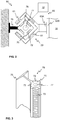
- Figure 3 illustrates schematically a part of the stator beam 70, or a stator beam part, according to an embodiment of the present invention by a perspective view.
- the part of the stator beam 70 comprises at least one stator 72 extending substantially along the whole stator beam 70.
- the fastening portion 75 may also be a separate fastening portion which may then be attached to the stator beam 70 for arranging the stator beam 70 into the elevator shaft 13 or the fastening portion 75 may be an integrated part of the stator beam 70 or a part thereof.
- the stators 72 may, preferably, be of ferromagnetic material and comprise teeth on their outer surface for providing a suitable magnetic circuit for co-acting with the mover 60.
- the stator beam 70 or beams 70 are passive in the sense that they do not comprise controllable elements or components, such as coils, for controlling the movement of the mover 60 along the stator beam 70.
- a stator 72 or each of the stators 72 may be attached to the stator beam 70 by having suitable shape or a recess into which the stator 72 may be arranged in, that is, by interlocking the stator(s) 72 to the stator beam 70. This may be implemented by having protruding portions in the stator beam 70 for keeping the stator 72 in place.
- the stator 72 or stators 72 may be, for example, slid into place, or into the recess arranged to the stator beam 70, from one end of the stator beam 72.
- the stator 72 may be attached to the stator beam 70 by using adhesives, such as using introducing glue on the back of the stator 72 before arranging the stator 72 into to the recess in the stator beam 70.
- the mover 60 according to the present invention may comprise at least one, preferably at least two or three, portions by which at least one characteristic, for example a floor position or an air gap width of the electric linear motor, or a value of electromotive force together with an airgap width, and a position information, such as an absolute or relative or incremental position, may be determined, while other portions may be used for propulsion force generation and, optionally, also for normal or levitation force generation.
- each of the portions may comprise windings or at least coil or coils which can be independently operated with respect to the other portions.
- one or several, or each one, of the portions may comprise a sensor or sensors, such as proximity sensor(s), for determining the at least one characteristic.
- the portion, being part of the movable unit 10 may be configured to determine such characteristic related to the electric linear motor 50 and/or the elevator shaft 13.
- FIG 4 illustrates schematically an electric linear motor 50 according to an embodiment of the present invention.
- the electric linear motor 50 may comprise a mover 60 and a stator beam 70.
- the mover 60 may comprise a unit or units of electromagnetic components 61.
- One or several of the units 61 may be divided, at least functionally, if not mechanically, into a plurality, that is at least two, three, or four, for instance, of base motors 62A-62D or motor subunits 62A-62D.
- the unit 61 defines four base motors 62A-62D or motor subunits 62A-62D.
- the base motors 62A-62D may, preferably, be independently controllable or operable.
- three of the base motors 62A-62D, including outermost ones 62A, 62D, are arranged to be utilized for propulsion force generation.
- said three base motors may in addition be used for normal or levitation force generation.
- one of the base motors 62A-62D in the middle may be utilized for determining at least one characteristic, such as a floor position or an air gap width of the electric linear motor 50, at a plurality of elevator shaft positions by a sensor of the first movable unit 10 during the movement of the unit 10. This may require stopping the modulation of the selected base motor in the middle 62B, 62C, and then, when the mover 60 is moved along the stator beam 70, recording the at least one characteristic, for example electromotive force together with an airgap width and a position information, such as an absolute or a relative position.
- at least one characteristic such as a floor position or an air gap width of the electric linear motor 50
- the mover 60 may comprise, as shown in the enlarged view at 200, permanent magnets 64A, 64B, coils 68, and ferromagnetic material 66 or an iron core 66 defining a magnetic circuit in the mover 60, such as also defining a yoke between mover teeth 69.
- the mover 60 may comprise mover teeth 69
- the stator 72 may comprise stator teeth 74.
- the air gap width between the mover 60 and the stator 70 may be determined based on the distance between a mover tooth 69 and a stator tooth 74 when being aligned, or based on the perpendicular distance therebetween.
- the unit 61 comprises individually controllable coils of the winding, such as controlled by an H-bridge type converter
- a plurality, such as three, individual middle coils of each unit 61 may be utilized for recording the at least one characteristic, for example electromotive force together with an airgap width and a position information, such as an absolute or a relative position, while other coils are utilized for propulsion and levitation force generation.
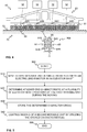
- Figure 5 shows a flow diagram of a method in accordance with an embodiment of the present invention.
- Step 500 refers to a start-up phase of the method. Suitable equipment and components are obtained, and systems assembled and configured for operation.
- This may also entail that running normal motor setup routines so that motor can run along the stator beam, and/or activating the shaft and airgap positioning, and/or starting levitation of the mover 60, and thus the movable unit 10, with respect to the stator beam 70.
- Step 510 refers to moving a first movable unit 10, such as comprising one of the elevator cars or a motor unit, along a linear stator 72 of the electric linear motor 50 in the elevator shaft 13.
- Step 520 refers to determining at least one characteristic, such as a floor 19 position or an air gap width of the electric linear motor 50, at a plurality of elevator shaft positions by the first movable unit 10, such as by a winding, a coil, or a sensor, during the moving.
- the first movable unit 10 such as by a winding, a coil, or a sensor
- the mover 60 of the electric linear motor 50 may comprise a plurality of independently controllable base motors 62A-62D or motor subunits 62A-62D, preferably, arranged consecutively in a longitudinal direction of the mover 60.
- the method may then comprise controlling movement of the mover 60 along the linear stator 72 by at least one of the plurality of independently controllable base motors 62A-62D or motor subunits 62A-62D, and determining the at least one characteristic by at least one other of the plurality of independently controllable base motors 62A-62D or motor subunits 62A-62D.
- the electric linear motor 50 may comprise at least three or four independently controllable base motors 62A-62D or motor subunits 62A-62D, and the method may comprise controlling the movement of the mover 60 along the linear stator 72 by at least by the outermost base motors 62A, 62D or motor subunits 62A, 62D, or in addition one of the middle base motors 62A, 62D or motor subunits 62A, 62D.
- the at least one characteristic may be a width of an air gap of the electric linear motor 50.
- the at least one characteristic may be an electromotive force (EMF) value in the plurality of positions along the stator 72.
- EMF electromotive force
- the EMF value depends on the airgap between stator 72 and mover 60, specifically the units of electromagnetic components 61 thereof.
- the EMF value variation thus corresponds to the stator surface variation, for example, due to a stator joint or joints, that is, joints between the stator beam parts 70, and/or joint(s) between the stator 72 and an element, such as a stator beam part thereof, of the direction changing position 20.
- the element of the direction changing position 20 may be arranged to be rotated or moved relative to the adjacent stator beam part 70 of the stator 72 in order to change the direction of movement of the movable unit 10, such as from vertical to horizontal, or vice versa, or between any two directions defined by the stator beam parts 70.
- the stator beam part 70 and the element may be arranged to be rotated or moved relative to the adjacent stator beam part 70 of the stator 72 in order to change the direction of movement of the movable unit 10, such as from vertical to horizontal, or vice versa, or between any two directions defined by the stator beam parts 70.
- the at least one characteristic may include position or distance data, such as positions of final limits, floors, and/or door zones, based on position indicators, such as an optical or a magnetic code tap.
- the at least one characteristic may include position or distance data related to the direction changing position 20 or positions 20 based on position indicators, such as an optical or a magnetic code tap, or based on measuring the EMF value at the gap/joint therebetween as described hereinbefore.
- the at least one characteristic based on the width of the air gap and/or to the EMF value, may be
- Step 530 refers to storing the determined at least one characteristic.
- the storing may be done into a memory comprised in the first movable unit 10, and/or in connection with the elevator control unit 1100, such as having a non-volatile memory device.
- the stored data may comprise the at least one characteristic, such as related to the air gap width, as a function with the elevator shaft position.
- the stored value may be used in other movable units 10, or even later in the same unit 10, when the position of the movable unit 10 is known and compared to the position information being stored.
- the method may comprise storing the determined at least one characteristic to a memory device of the second movable unit 10.
- Step 540 refers to controlling moving of at least a second movable unit, such as comprising another of the elevator cars or a second motor unit, by utilizing the stored at least one characteristic.
- the method may comprise controlling of the moving of at least one second movable unit 10 by controlling electrical current supplied to the electric linear motor 50 based on the determined air gap and electromotive force at the plurality of positions of the elevator shaft 13.
- the stored at least one characteristic may be used in controlling the moving of the second movable unit 10 by utilizing the stored information in the controller of the mover 60.
- the information is used in a current controller, or controllers, of the electrical converter 12 operating the mover 60. This may be implemented by adding a feed-forward term into the control loop; the feed-forward term being based on the stored characteristic.
- the stored information is used as feed-forward terms in either one or both of the quadrature (q) and the direct (d) axis current controllers.
- Method execution is ended at step 599.
- the method may be performed once, intermittently, periodically, continuously or, on demand.
- the method provides the effect that, when a multi-car elevator is commissioned (or the shaft setup has been lost or changed), a single movable unit 10, such as an elevator car or a motor unit, can be used to drive through all the shaft sections.
- the movable unit 10 determines and stores, such as in non-volatile memory, all position indicators in the elevator shaft 13 (for example final limits, floors, door zones etc.) and measures the distance between them using, for example, encoder, incremental or absolute positioning system, depending on the embodiment.
- the method may comprise updating, such as when the method is being performed many times, the stored at least one characteristic by any one of the movable units 10 when moving along the linear stator 72 of the electric linear motor 50 in the elevator shaft 13.
- Absolute and/or incremental positioning system may be an additional processing logic relying on an encoder signal and other positioning indicators, or a separate system based on, for example, magnetic or optical code tape installed in the shaft 13.
- the positioning system such as an incremental positioning system, may comprise having certain markers arranged into the stator 72 or elsewhere in the stator beam 70; the markers being, for example, magnetic teeth or auxiliary markers. These markers may be detectable by utilizing the unit of electromagnetic components 61 in the mover 60, or by a separate sensor, for example, based on infrared, light, capacitance, or inductance, etc.
- absolute positioning system is based on incremental number read from, for example, optical or magnetic code tape
- also relevant position code information is saved (for example, the code in the beginning and in the end of each shaft section). Then when one movable unit 10 has finished the shaft setup process, the shaft information can then be copied to all other movable units 10 so that they will know the shaft information without any additional shaft setup drive.
- the sharing information about the at least one characteristic can, alternatively or in addition, be used to counteract inaccuracies in positioning system caused by thermal expansion of positioning code tape or guide rail. If one or more movable units 10, during normal use, detect that distance between floors 19 differs from that stored during the shaft setup by a movable unit 10, a correction information could then be communicated to all other movable units 10.
Landscapes
- Engineering & Computer Science (AREA)
- Automation & Control Theory (AREA)
- Computer Networks & Wireless Communication (AREA)
- Power Engineering (AREA)
- Mechanical Engineering (AREA)
- Structural Engineering (AREA)
- Civil Engineering (AREA)
- Electromagnetism (AREA)
- Physics & Mathematics (AREA)
- Combustion & Propulsion (AREA)
- Chemical & Material Sciences (AREA)
- Linear Motors (AREA)
- Control Of Linear Motors (AREA)
- Elevator Control (AREA)
- Indicating And Signalling Devices For Elevators (AREA)
- Cage And Drive Apparatuses For Elevators (AREA)
- Types And Forms Of Lifts (AREA)
Abstract
Description
- The present invention relates in general to elevators. In particular, however not exclusively, the present invention concerns operating an elevator, especially, commissioning it for use.
- There are known elevators with linear motors. In such elevators, bending of the linear parts of the motor or possible unevenness thereof can cause issues to the ride comfort. Installation of the linear parts of the motors have certainly higher tolerances compared to rotating motor solutions, such as in traditional elevators, that are centered by mechanical bearing. Also, joints between the linear parts can play a role in ride comfort, especially in turning stations, where there might be relatively long gaps.
- On the other hand, shaft setup is part of the elevator commissioning process. An elevator car is slowly driven through the whole shaft reading all installed position indicators, measures the distance travelled using typically car and/or motor encoders and in some cases absolute position sensor, and then saves the information in a memory.
- In elevators having a plurality of elevator cars, the conventional shaft setup process is time consuming due to high number of cars in the elevator shafts. Possibility to move also horizontally makes the shaft setup process even more challenging. If the elevator includes of, for example 40 elevator cars, 3 vertical shafts and 6 horizontal paths, driving all elevator cars through all shaft sections could take even days.
- An objective of the present invention is to provide a method for operating an elevator and an elevator. Another objective of the present invention is that the method and the elevator alleviates at least some of the drawbacks of the known elevators, such as related to ride comfort and/or commissioning.
- The objectives of the invention are reached by a method and an elevator as defined by the respective independent claims.
- According to a first aspect, a method for operating, such as commissioning, an elevator is provided, wherein the elevator comprises an electric linear motor for moving movable units, such as elevator cars or motor units, in an elevator shaft. The method comprises:
- moving a first movable unit, such as comprising one of the elevator cars or a motor unit, along a linear stator of the electric linear motor in the elevator shaft,
- determining at least one characteristic, such as a floor position or an air gap width of the electric linear motor, at a plurality of elevator shaft positions by the first movable unit, such as by a winding, a coil, or a sensor, during the moving,
- storing the determined at least one characteristic, and
- controlling moving of at least a second movable unit, such as comprising another of the elevator cars or a second motor unit, by utilizing the stored at least one characteristic.
- The movable unit, such as the first movable unit and/or the second movable unit, according to the present invention may refer, for example, to an elevator car which is arranged to be moved by a mover or movers of an electric linear motor of the elevator in the elevator shaft. However, alternatively, the movable unit(s) may refer to a motor unit. The motor unit may be, in some embodiments, the mover of the electric linear motor which may be moved as such in the elevator shaft. The motor unit may, preferably, also comprise electrical power providing means for providing electrical power to the mover, such as from an electrical energy storage, for example, a battery or batteries. Furthermore, the motor unit may comprise a controller for controlling the movement. The elevator car, or specifically the "cage" into which the passengers enter, may then be removably coupled to the motor unit for moving the elevator car. However, in various embodiments, the motor unit may be arranged to be moved in the elevator shaft and along the stator beam independently of the elevator car.
- In various embodiments, the method may comprise storing the determined at least one characteristic to a memory device of the second movable unit.
- In various embodiments, the method may comprise storing the determined at least one characteristic to an elevator control unit, such as having a non-volatile memory device.
- In some embodiments, the at least one characteristic may include position or distance data, such as positions of final limits, floors, and/or door zones, and/or related to a direction changing position, based on position indicators, such as an optical or a magnetic code tap.
- In some embodiments, the linear stator may comprise markers, such as magnetic teeth or auxiliary markers, for indicating positions.
- In various embodiments, the method may comprise updating the stored at least one characteristic by any one of said movable units when moving along the linear stator of the electric linear motor in the elevator shaft.
- In some embodiments, the at least one characteristic may be a width of an air gap of the electric linear motor. Alternatively or in addition, the at least one characteristic may relate to electromotive force of the electric linear motor. Furthermore, the method may comprise controlling moving of at least a second movable unit by controlling electrical current supplied to the electric linear motor based on the determined air gap and electromotive force at the plurality of positions of the elevator shaft.
- In various embodiments, a mover of the electric linear motor comprises a plurality of independently controllable base motors or motor subunits, wherein the method may comprise controlling movement of the mover along the linear stator by at least one of the plurality of independently controllable base motors or motor subunits, and determining the at least one characteristic by at least one other of the plurality of independently controllable base motors or motor subunits. In addition, the electric linear motor may comprise at least three or four independently controllable base motors or motor subunits, wherein the method may comprise controlling the movement of the mover along the linear stator by at least by the outermost base motors or motor subunits.
- According to a second aspect, an elevator is provided. The elevator comprises an electric linear motor for moving movable units, such as elevator cars or motor units, in an elevator shaft, wherein the electric linear motor comprises a linear stator extending in the elevator shaft. The elevator further comprises a first movable unit, such as comprising one of the elevator cars or a motor unit, arranged to be moved along the linear stator and configured for determining at least one characteristic, such as a floor position or an air gap width of the electric linear motor, at a plurality of elevator shaft positions by the first movable unit during the moving. Still further, the elevator comprises a second movable unit, such as comprising another of the elevator cars or a second motor unit, by utilizing the stored at least one characteristic. The first movable unit is configured determine and store the at least one characteristic during moving along the linear stator, and the second movable unit is configured to utilize the stored at least one characteristic, such as in a memory device, for controlling its moving along the linear stator.
- In various embodiments, the at least one characteristic may be position or distance data, such as positions of final limits, floors, and/or door zones, and/or related to a direction changing position, based on position indicators, such as an optical or a magnetic code tap. Alternatively or in addition, the at least one characteristic may be an air gap width and/or an electromotive force of the electric linear motor.
- In some embodiments, at least the first movable unit may comprise a mover of the electric linear motor comprising a plurality of independently controllable base motors or motor subunits. In addition, the first movable unit may be configured to control movement of the mover along the linear stator by at least one of the plurality of independently controllable base motors or motor subunits, and to determine the at least one characteristic by at least one other of the plurality of independently controllable base motors or motor subunits.
- The present invention provides a method for operating an elevator and an elevator. The present invention provides advantages over known solutions in that shaft setup information is used for controlling the propulsion force and, optionally, normal force generated by the motor. This improves ride comfort issues due to inaccuracy and also saves a lot of time in shaft setup in multi-car elevators. This is especially critical in cases, where shaft setup of an operating elevator has been lost for some reason. The higher the number of cars is, the bigger the benefit.
- Various embodiments of the present invention make the installation of position-code based absolute positioning system of the elevator easier. Typically, these kinds of systems have continuous, incremental position code throughout the whole shaft. In multi-car elevators, elevator run is not a single straight line, which would be a challenge for code tape installation. Inevitably there will be discontinuities in position code if the travel path changes from vertical to horizontal. This could be solved by preparing special dedicated code tapes for certain shaft sections, which would make the installation challenging. Using method proposed in this invention and saving the code tape information during the shaft setup (and sharing the information between cars), would eliminate the need of dedicated code tapes.
- Various other advantages will become clear to a skilled person based on the following detailed description.
- The expression "a plurality of" may refer to any positive integer starting from two (2), that is, being at least two.
- The terms "first", "second" and "third" are herein used to distinguish one element from another element, and not to specially prioritize or order them, if not otherwise explicitly stated.
- The exemplary embodiments of the present invention presented herein are not to be interpreted to pose limitations to the applicability of the appended claims. The verb "to comprise" is used herein as an open limitation that does not exclude the existence of also unrecited features. The features recited in depending claims are mutually freely combinable unless otherwise explicitly stated.
- The novel features which are considered as characteristic of the present invention are set forth in particular in the appended claims. The present invention itself, however, both as to its construction and its method of operation, together with additional objectives and advantages thereof, will be best understood from the following description of specific embodiments when read in connection with the accompanying drawings.
- Some embodiments of the invention are illustrated by way of example, and not by way of limitation, in the figures of the accompanying drawings.
-
Figure 1 illustrates schematically an elevator according to an embodiment of the present invention. -
Figure 2 illustrates schematically an electric linear motor according to an embodiment of the present invention. -
Figure 3 illustrates schematically an electric linear motor according to an embodiment of the present invention. -
Figure 4 illustrates schematically an electric linear motor according to an embodiment of the present invention. -
Figure 5 illustrates a flow diagram of a method according to an embodiment of the present invention. -
Figure 1 illustrates schematically anelevator 100 according to an embodiment of the present invention. Theelevator 100 may comprise at least one or a plurality ofmovable units 10, such as elevator cars or motor units, moving in theelevator shaft 13 or theelevator car pathway 13. - The
movable unit 10 according to the present invention may refer, for example, to an elevator car which may, preferably, be arranged to be moved by amover 60 ormovers 60 of an electric linear motor of the elevator in theelevator shaft 13. Only onemover 60 is shown inFig. 1 for the sake of legibility. However, alternatively, the movable unit(s) 10 may refer to one or several motor units. The motor unit may be, in some embodiments, essentially a mover of the electric linear motor which may be moved as such in the elevator shaft. The motor unit may, preferably, also comprise electrical power providing means for providing electrical power to the mover, such as from an electrical energy storage, for example, a battery or batteries. Furthermore, the motor unit may comprise a controller for controlling the movement, such as including an electrical converter, such as an inverter. The elevator car, or specifically the "cage" into which the passengers enter, may then be removably coupled to the motor unit for moving the elevator car. However, in various embodiments, the motor unit may be arranged to be moved in the elevator shaft and along the stator beam independently of the elevator car. - There are preferably at least two landing floors, having
landing floor doors 19 oropenings 19, comprised in theelevator 100. There may also be doors comprised in themovable unit 10, such as an elevator car. Although shown inFig. 1 that there are two horizontally separated sets, or "columns", of vertically aligned landing floors, there could as well be only one column, that is vertical shafts, as in conventional elevators or more than two, for example, three, or even more. - There can be as fewer, as many or more horizontal paths from one vertical shaft to another compared to the number of vertical shafts.
- Regarding the
elevator shaft 13, it may be such as defining substantially closed volume in which themovable unit 10 is adapted and configured to be moved. The walls may be, for example, of concrete, metal or at least partly of glass, or any combination thereof. Theelevator shaft 13 herein refers basically to any structure or pathway along which themovable unit 10 is configured to be moved. - As can be seen in
Fig. 1 with respect to theelevator 100, themovable unit 10 orcars 10, that is a multi-car elevator, may be moved along theelevator shaft 13 vertically and/or horizontally depending on the direction of stator beams 70. According to embodiments similar to one inFig. 1 in this respect, themovable unit 10 orunits 10 may be configured to be moved along at least one of vertical 70 and/or horizontal 70 stator beams, for example, two beams such as inFig. 1 . The stator beams 70 are part of an electric linear motor of theelevator 100 utilized to move themovable unit 10 orunits 10 in theelevator shaft 13. The stator beams 70 may, preferably, be arranged in fixed manner, that is, stationary with respect to theelevator shaft 13, for example, to a wall of the shaft by fastening portions, which may be arranged to rotatable atdirection changing positions 20 of themovable unit 10. - The
elevator 100 may comprise anelevator control unit 1100 for controlling the operation of theelevator 100, such as the device or devices. Theelevator control unit 1100 may be a separate device or may be comprised in the other components of theelevator 100. Theelevator control unit 1100 may also be implemented in a distributed manner so that, e.g., one portion of theelevator control unit 1100 may be comprised in the electrical converter unit and another portion in themovable unit 10 and/or in theelevator shaft 13. Theelevator control unit 1100 may also be arranged in distributed manner at more than two locations or in more than two devices. Advantageously, theelevator control unit 1100 has been arranged to be in connection, such as in electrical connection and/or in data communication, with the device(s) and, optionally, movable unit(s) 10. - The
elevator control unit 1100 may comprise one or more processors, one or more memories being volatile or non-volatile for storing portions of computer program code and any data values and possibly one or more user interface units. The mentioned elements may be communicatively coupled to each other with e.g. an internal bus. - The processor of the
elevator control unit 1100 may at least be configured to perform various tasks related to the operation of theelevator 100. The implementation of such tasks may be achieved by arranging the processor to execute at least some portion of computer program code stored in the memory causing the processor, and thus theelevator control unit 1100, to implement one or more the tasks. The processor may thus be arranged to access the memory and retrieve and store any information therefrom and thereto. For sake of clarity, the processor herein refers to any unit suitable for processing information and control the operation of theelevator control unit 1100, among other tasks. The operations may also be implemented with a microcontroller solution with embedded software. Similarly, the memory is not limited to a certain type of memory only, but any memory type suitable for storing the described pieces of information may be applied in the context of the present invention. -
Figure 2 illustrates schematically an electriclinear motor 50, or at least a part thereof, according to an embodiment of the present invention. The electriclinear motor 50 may comprise amover 60, preferably, a C-shaped or U-shaped (not shown)mover 60. Themover 60 may comprise at least one or several permanent magnets and/or magnetic core element(s) or ferromagnetic material, and optionally, a unit or units ofelectromagnetic components 61 comprising at least one coil or winding. The unit or units ofelectromagnetic components 61 may, preferably, be comprised in themover 60 and adapted to face thestator 72 orstators 72 of thestator beam 70, as shown inFig. 2 , for instance. There may also be asupport portion 63A by whichmover 60 may be attached or coupled to themovable unit 10, for example, to the back wall of thecar 10. As can be seen, themover 60 may be shaped and designed in such a way as to enable the movement of themover 60 along thestator beam 70 without interference from the fastening orsupport portions further support portions 63B utilized to attach themover 60 to themovable unit 10. Thefurther support portion 63B may be rotatable, for instance. - In some embodiments, the
mover 60 or themovers 60 may be part of a motor unit. The motor unit may, preferably, also comprise electrical power providing means for providing electrical power to the mover, such as from an electrical energy storage, for example, a battery or batteries. Furthermore, the motor unit may comprise a controller for controlling the movement. The elevator car, or specifically the "cage" into which the passengers can enter, may then be removably coupled to the motor unit for moving the elevator car. However, in various embodiments, the motor unit may be arranged to be moved in the elevator shaft and along the stator beam independently of the elevator car or any elevator car of the elevator. - The movement of the
mover 60 along thestator beam 70 may be implemented by known control methods, such as, field-oriented or vector control or the like. The basic idea is to produce an alternating magnetic field, for example by anelectrical converter 12, such as an inverter, for example a three-phase inverter, by injecting current to a unit ofelectromagnetic components 61 of themover 60, such as to a winding or coil thereof. The unit ofelectromagnetic components 61 facing thestator 72 then co-acts with thestator 72 through the electromagnetic engagement and produces a force which moves themover 60 and thus, optionally, themovable unit 10 along thestator beam 70. - According to a preferable embodiment of the present invention, the
stator beam 70, as shown inFig. 2 , may comprise at least onestator 72, however, preferably two or fourstators 72 arranged on opposite or each side of thestator beam 70. Thestator beam 70 further comprises abeam part 76 which, in some embodiments, may be made mainly of non-magnetic material, that is, material that is not capable of being magnetized. "Capable of being magnetized" refers herein to a degree of magnetization which may be regarded as magnetization suitable for being utilized in magnetic circuits in a typical manner and, thus, relates to materials which are substantially affected by the magnetic field or flux. Non-magnetic materials may be those which are not affected or are slightly affected by magnetic field or flux. Non-magnetic materials may be, for example, paramagnetic, diamagnetic or weakly ferromagnetic materials, or combinations thereof, with a relative magnetic permeability less than or equal to 2.0 or advantageously less than or equal to 1.5. In general, thebeam part 76 may comprise non-metal, preferably non-magnetic, material. These materials may include, for example, however, not limited to, polymers, or polymer composites, wood, and/or glass. According to some embodiments of the present invention, thebeam part 76 material may comprise glass fibre(s) or carbon fibre(s). According to some embodiments, the parts made of fibre material, such as aramid fibre, may be coated with material withstanding heat in order to improve the resistance of the fibre material to heat, for example in case of a building fire. The use of aramid fibres can be advantageous due to its ability to withstand mechanical impulses better than glass or carbon fibres. - The use of carbon fibre material in the
beam part 76 provides a surprising advantage, in addition to other factors such as low weight, by its negative coefficient of thermal expansion. For example, if the temperature of thestator 72 increases and, thus thestator 72 expands, thebeam part 76 may be used to provide compensation by shrinking, as thestator beam 70 is fixedly attached to the surrounding structures, due to its negative thermal expansion coefficient, that is, giving more room for thestator 72 to expand and alleviating the mechanical stress caused by the expansion of thestator 72 to thestator beam 70. - According to various embodiments of the present invention, the
stator beam 70 may further comprise ahole 77 or arecess 77 or a through-hole 77, that is, thestator beam 70 is hollow, essentially in thestator beam 70. Thehole 77 may be utilized for locking and/or aligning consecutive stator beam parts together, for example, by a pin or a dowel. The dowel may be inserted into theholes 77 of both of the consecutive stator beam parts or only other one of the stator beam parts comprises the hole while the other comprises the dowel as a counter-part for the aligning and, preferably, locking the stator beam parts relative to each other. The through-hole 77 further reduces the mass of thestator beam 70. - Manufacturing the
stator beam 70 of non-magnetic, such as composite, material, for example, glass fibre composite, facilitates an accurate manufacturing of thestator beam 70 with respect to manufacturing of conventional stator beams which are manufactured by using ferromagnetic material, such as steel, having high permeability and thus significant magnetic properties. Furthermore, thestator beam 70 made of non-magnetic material as described herein also facilitates the installation and operation of the electric linear motor as thecomposite stator beam 70, such as comprising glass or carbon fibre material, undergoes less thermal expansion relative to conventional stator beams 70. Still another benefit of using thecomposite stator beam 70 is that composite is non-magnetic material unlike some metals and thus affects less the operation of the magnetic circuit of the linear electric motor. Thestators 72 arranged to thestator beam 70 of non-magnetic material, such as of composite, facilitates designing the motor from the magnetic coupling between themover 60 and thestator 72 point of view. -
Figure 3 illustrates schematically a part of thestator beam 70, or a stator beam part, according to an embodiment of the present invention by a perspective view. The part of thestator beam 70 comprises at least onestator 72 extending substantially along thewhole stator beam 70. There may, advantageously, be fourstators 72 arranged at all four sides of thestator beam 70, such as inFig. 3 . There may also be afastening portion 75 orportions 75 by which saidpart 70 may be attached in fixed manner to the structures, such as a wall, of theelevator shaft 13. Thefastening portion 75 may also be a separate fastening portion which may then be attached to thestator beam 70 for arranging thestator beam 70 into theelevator shaft 13 or thefastening portion 75 may be an integrated part of thestator beam 70 or a part thereof. Thestators 72 may, preferably, be of ferromagnetic material and comprise teeth on their outer surface for providing a suitable magnetic circuit for co-acting with themover 60. According to a preferable embodiment of the present invention, thestator beam 70 orbeams 70 are passive in the sense that they do not comprise controllable elements or components, such as coils, for controlling the movement of themover 60 along thestator beam 70. - In
Fig. 3 , astator 72 or each of thestators 72 may be attached to thestator beam 70 by having suitable shape or a recess into which thestator 72 may be arranged in, that is, by interlocking the stator(s) 72 to thestator beam 70. This may be implemented by having protruding portions in thestator beam 70 for keeping thestator 72 in place. Thestator 72 orstators 72 may be, for example, slid into place, or into the recess arranged to thestator beam 70, from one end of thestator beam 72. Alternatively or in addition, thestator 72 may be attached to thestator beam 70 by using adhesives, such as using introducing glue on the back of thestator 72 before arranging thestator 72 into to the recess in thestator beam 70. - In some embodiments, the
mover 60 according to the present invention, either being coupled to the elevator car or being part of the motor unit, may comprise at least one, preferably at least two or three, portions by which at least one characteristic, for example a floor position or an air gap width of the electric linear motor, or a value of electromotive force together with an airgap width, and a position information, such as an absolute or relative or incremental position, may be determined, while other portions may be used for propulsion force generation and, optionally, also for normal or levitation force generation. In some embodiments, each of the portions may comprise windings or at least coil or coils which can be independently operated with respect to the other portions. Alternatively or in addition, one or several, or each one, of the portions may comprise a sensor or sensors, such as proximity sensor(s), for determining the at least one characteristic. Regardless of the embodiment, the portion, being part of themovable unit 10, may be configured to determine such characteristic related to the electriclinear motor 50 and/or theelevator shaft 13. -
Figure 4 illustrates schematically an electriclinear motor 50 according to an embodiment of the present invention. The electriclinear motor 50 may comprise amover 60 and astator beam 70. Themover 60 may comprise a unit or units ofelectromagnetic components 61. One or several of theunits 61 may be divided, at least functionally, if not mechanically, into a plurality, that is at least two, three, or four, for instance, ofbase motors 62A-62D ormotor subunits 62A-62D. - In
Fig. 4 , theunit 61 defines fourbase motors 62A-62D ormotor subunits 62A-62D. Thebase motors 62A-62D may, preferably, be independently controllable or operable. In an embodiment, three of thebase motors 62A-62D, includingoutermost ones unit 61 and/or themover 60 relative to the normal direction. However, one of thebase motors 62A-62D in the middle, that is marked with 62B or 62C, may be utilized for determining at least one characteristic, such as a floor position or an air gap width of the electriclinear motor 50, at a plurality of elevator shaft positions by a sensor of the firstmovable unit 10 during the movement of theunit 10. This may require stopping the modulation of the selected base motor in the middle 62B, 62C, and then, when themover 60 is moved along thestator beam 70, recording the at least one characteristic, for example electromotive force together with an airgap width and a position information, such as an absolute or a relative position. - In various embodiments, the
mover 60 may comprise, as shown in the enlarged view at 200,permanent magnets ferromagnetic material 66 or aniron core 66 defining a magnetic circuit in themover 60, such as also defining a yoke betweenmover teeth 69. - Furthermore, the
mover 60 may comprisemover teeth 69, and thestator 72 may comprisestator teeth 74. Thus, the air gap width between themover 60 and thestator 70 may be determined based on the distance between amover tooth 69 and astator tooth 74 when being aligned, or based on the perpendicular distance therebetween. - According to another embodiment in which the
unit 61 comprises individually controllable coils of the winding, such as controlled by an H-bridge type converter, a plurality, such as three, individual middle coils of eachunit 61 may be utilized for recording the at least one characteristic, for example electromotive force together with an airgap width and a position information, such as an absolute or a relative position, while other coils are utilized for propulsion and levitation force generation. -
Figure 5 shows a flow diagram of a method in accordance with an embodiment of the present invention. - Step 500 refers to a start-up phase of the method. Suitable equipment and components are obtained, and systems assembled and configured for operation.
- This may also entail that running normal motor setup routines so that motor can run along the stator beam, and/or activating the shaft and airgap positioning, and/or starting levitation of the
mover 60, and thus themovable unit 10, with respect to thestator beam 70. - Step 510 refers to moving a first
movable unit 10, such as comprising one of the elevator cars or a motor unit, along alinear stator 72 of the electriclinear motor 50 in theelevator shaft 13. - Step 520 refers to determining at least one characteristic, such as a
floor 19 position or an air gap width of the electriclinear motor 50, at a plurality of elevator shaft positions by the firstmovable unit 10, such as by a winding, a coil, or a sensor, during the moving. - In various embodiments, the
mover 60 of the electriclinear motor 50 may comprise a plurality of independentlycontrollable base motors 62A-62D ormotor subunits 62A-62D, preferably, arranged consecutively in a longitudinal direction of themover 60. The method may then comprise controlling movement of themover 60 along thelinear stator 72 by at least one of the plurality of independentlycontrollable base motors 62A-62D ormotor subunits 62A-62D, and determining the at least one characteristic by at least one other of the plurality of independentlycontrollable base motors 62A-62D ormotor subunits 62A-62D. - Alternatively or in addition, the electric
linear motor 50 may comprise at least three or four independentlycontrollable base motors 62A-62D ormotor subunits 62A-62D, and the method may comprise controlling the movement of themover 60 along thelinear stator 72 by at least by theoutermost base motors motor subunits middle base motors motor subunits - In some embodiments, the at least one characteristic may be a width of an air gap of the electric
linear motor 50. - In various embodiments, the at least one characteristic may be an electromotive force (EMF) value in the plurality of positions along the
stator 72. The EMF value depends on the airgap betweenstator 72 andmover 60, specifically the units ofelectromagnetic components 61 thereof. The EMF value variation thus corresponds to the stator surface variation, for example, due to a stator joint or joints, that is, joints between thestator beam parts 70, and/or joint(s) between thestator 72 and an element, such as a stator beam part thereof, of thedirection changing position 20. - In various embodiments, the element of the
direction changing position 20 may be arranged to be rotated or moved relative to the adjacentstator beam part 70 of thestator 72 in order to change the direction of movement of themovable unit 10, such as from vertical to horizontal, or vice versa, or between any two directions defined by thestator beam parts 70. Thus, there may be a gap between saidstator beam part 70 and the element in order to be able to move said components with respect to each other. This has an effect on the EMF at said positions. - Alternatively or in addition, the at least one characteristic may include position or distance data, such as positions of final limits, floors, and/or door zones, based on position indicators, such as an optical or a magnetic code tap.
- Alternatively or in addition, the at least one characteristic may include position or distance data related to the
direction changing position 20 orpositions 20 based on position indicators, such as an optical or a magnetic code tap, or based on measuring the EMF value at the gap/joint therebetween as described hereinbefore. - In various embodiments, alternatively or in addition, the at least one characteristic, based on the width of the air gap and/or to the EMF value, may be
- Step 530 refers to storing the determined at least one characteristic. The storing may be done into a memory comprised in the first
movable unit 10, and/or in connection with theelevator control unit 1100, such as having a non-volatile memory device. The stored data may comprise the at least one characteristic, such as related to the air gap width, as a function with the elevator shaft position. Thus, the stored value may be used in othermovable units 10, or even later in thesame unit 10, when the position of themovable unit 10 is known and compared to the position information being stored. - In some embodiments, the method may comprise storing the determined at least one characteristic to a memory device of the second
movable unit 10. - Step 540 refers to controlling moving of at least a second movable unit, such as comprising another of the elevator cars or a second motor unit, by utilizing the stored at least one characteristic. In addition, the method may comprise controlling of the moving of at least one second
movable unit 10 by controlling electrical current supplied to the electriclinear motor 50 based on the determined air gap and electromotive force at the plurality of positions of theelevator shaft 13. - In various embodiments, the stored at least one characteristic may be used in controlling the moving of the second
movable unit 10 by utilizing the stored information in the controller of themover 60. In an embodiment, the information is used in a current controller, or controllers, of theelectrical converter 12 operating themover 60. This may be implemented by adding a feed-forward term into the control loop; the feed-forward term being based on the stored characteristic. In an embodiment, the stored information is used as feed-forward terms in either one or both of the quadrature (q) and the direct (d) axis current controllers. Thus, as the operation of themover 60 is controlled based on the stored characteristic, the propulsion and/or levitation force components can be controlled based on the position of themovable unit 10 in theelevator shaft 13. The advantage is that this improves ride comfort which would otherwise be compromised due to the inaccuracies in the electriclinear motor 50, that is between themover 60 and thelinear stator 72. - Method execution is ended at
step 599. The method may be performed once, intermittently, periodically, continuously or, on demand. - Thus, the method provides the effect that, when a multi-car elevator is commissioned (or the shaft setup has been lost or changed), a single
movable unit 10, such as an elevator car or a motor unit, can be used to drive through all the shaft sections. During this process, themovable unit 10 determines and stores, such as in non-volatile memory, all position indicators in the elevator shaft 13 (for example final limits, floors, door zones etc.) and measures the distance between them using, for example, encoder, incremental or absolute positioning system, depending on the embodiment. - In some embodiments, the method may comprise updating, such as when the method is being performed many times, the stored at least one characteristic by any one of the
movable units 10 when moving along thelinear stator 72 of the electriclinear motor 50 in theelevator shaft 13. - Absolute and/or incremental positioning system may be an additional processing logic relying on an encoder signal and other positioning indicators, or a separate system based on, for example, magnetic or optical code tape installed in the
shaft 13. - Alternatively or in addition, the positioning system, such as an incremental positioning system, may comprise having certain markers arranged into the
stator 72 or elsewhere in thestator beam 70; the markers being, for example, magnetic teeth or auxiliary markers. These markers may be detectable by utilizing the unit ofelectromagnetic components 61 in themover 60, or by a separate sensor, for example, based on infrared, light, capacitance, or inductance, etc. - If absolute positioning system is based on incremental number read from, for example, optical or magnetic code tape, also relevant position code information is saved (for example, the code in the beginning and in the end of each shaft section). Then when one
movable unit 10 has finished the shaft setup process, the shaft information can then be copied to all othermovable units 10 so that they will know the shaft information without any additional shaft setup drive. - In some embodiment, the sharing information about the at least one characteristic can, alternatively or in addition, be used to counteract inaccuracies in positioning system caused by thermal expansion of positioning code tape or guide rail. If one or more
movable units 10, during normal use, detect that distance betweenfloors 19 differs from that stored during the shaft setup by amovable unit 10, a correction information could then be communicated to all othermovable units 10.
Claims (16)
- A method for operating, such as commissioning, an elevator (100), wherein the elevator (100) comprises an electric linear motor (50) for moving movable units (10), such as elevator cars or motor units, in an elevator shaft (13), characterized in that the method comprises:- moving (510) a first movable unit (10), such as comprising one of the elevator cars or a motor unit, along a linear stator (72) of the electric linear motor (50) in the elevator shaft (13);- determining (520) at least one characteristic, such as a floor position or an air gap width of the electric linear motor (50), at a plurality of elevator shaft positions by the first movable unit (10), such as by a winding, a coil, or a sensor, during the moving;- storing (530) the determined at least one characteristic; and- controlling (540) moving of at least a second movable unit (10), such as comprising another of the elevator cars or a second motor unit, by utilizing the stored at least one characteristic.
- The method of claim 1, comprising storing the determined at least one characteristic to a memory device of the second movable unit (10).
- The method of claim 1 or 2, comprising storing the determined at least one characteristic to an elevator control unit (1100), such as having a non-volatile memory device.
- The method of any one of the preceding claims, wherein the at least one characteristic includes position or distance data, such as positions of final limits, floors, and/or door zones, and/or related to a direction changing position (20), based on position indicators, such as an optical or a magnetic code tap.
- The method of any one of the preceding claims, wherein the linear stator (72) comprises markers, such as magnetic teeth or auxiliary markers, for indicating positions.
- The method of any one of the preceding claims, comprising updating the stored at least one characteristic by any one of said movable units (10) when moving along the linear stator (72) of the electric linear motor (50) in the elevator shaft (13).
- The method of any one of the preceding claims, wherein the at least one characteristic is a width of an air gap of the electric linear motor (50).
- The method of any one of the preceding claims, wherein the at least one characteristic relates to electromotive force of the electric linear motor (50).
- The method of claim 7 and 8, comprising controlling moving of at least a second movable unit (10) by controlling electrical current supplied to the electric linear motor (50) based on the determined air gap and electromotive force at the plurality of positions of the elevator shaft (13).
- The method of any one of the preceding claims, wherein a mover (60) of the electric linear motor (50) comprises a plurality of independently controllable base motors (62A-62D) or motor subunits (62A-62D), wherein the method comprises:- controlling movement of the mover along the linear stator by at least one of the plurality of independently controllable base motors (62A-62D) or motor subunits (62A-62D); and- determining the at least one characteristic by at least one other of the plurality of independently controllable base motors (62A-62D) or motor subunits (62A-62D).
- The method of claim 10, wherein the electric linear motor comprises at least three or four independently controllable base motors (62A-62D) or motor subunits (62A-62D), the method comprising:- controlling the movement of the mover along the linear stator by at least the outermost base motors (62A, 62D) or motor subunits (62A, 62D).
- An elevator (100), characterized in that it comprises:an electric linear motor (50) for moving movable units (10), such as elevator cars or motor units, in an elevator shaft (13), wherein the electric linear motor (50) comprises a linear stator (72) extending in the elevator shaft (13);a first movable unit (10), such as comprising one of the elevator cars or a motor unit, arranged to be moved along the linear stator (72) and configured for determining at least one characteristic, such as a floor position or an air gap width of the electric linear motor (50), at a plurality of elevator shaft positions by the first movable unit (10), such as by a winding, a coil, or a sensor, during the moving;a second movable unit (10), such as comprising another of the elevator cars or a second motor unit, by utilizing the stored at least one characteristic;wherein the first movable unit (10) is configured determine and store the at least one characteristic during moving along the linear stator (72); andwherein the second movable unit (10) is configured to utilize the stored at least one characteristic, such as in a memory device, for controlling its moving along the linear stator (72).
- The elevator of claim 12, wherein the at least one characteristic is position or distance data, such as positions of final limits, floors, and/or door zones, and/or related to a direction changing position (20), based on position indicators, such as an optical or a magnetic code tap.
- The elevator of claim 12 or 13, wherein the at least one characteristic is an air gap width and/or an electromotive force of the electric linear motor (50).
- The elevator of any one of claims 12-14, wherein at least the first movable unit (10) comprises a mover (60) of the electric linear motor (50) comprising a plurality of independently controllable base motors (62A-62D) or motor subunits (62A-62D).
- The elevator of claim 15, wherein the first movable unit (10) is configured to control movement of the mover (60) along the linear stator (72) by at least one of the plurality of independently controllable base motors (62A-62D) or motor subunits (62A-62D), and to determine the at least one characteristic by at least one other of the plurality of independently controllable base motors (62A-62D) or motor subunits (62A-62D).
Priority Applications (4)
| Application Number | Priority Date | Filing Date | Title |
|---|---|---|---|
| EP19210803.3A EP3825270B1 (en) | 2019-11-22 | 2019-11-22 | Method for operating an elevator and elevator |
| US17/072,687 US12497264B2 (en) | 2019-11-22 | 2020-10-16 | Method for operating an elevator and elevator |
| JP2020184835A JP7769467B2 (en) | 2019-11-22 | 2020-11-05 | Elevator operation method and elevator |
| CN202011303375.7A CN112830353B (en) | 2019-11-22 | 2020-11-19 | Method of operating an elevator and elevator |
Applications Claiming Priority (1)
| Application Number | Priority Date | Filing Date | Title |
|---|---|---|---|
| EP19210803.3A EP3825270B1 (en) | 2019-11-22 | 2019-11-22 | Method for operating an elevator and elevator |
Publications (2)
| Publication Number | Publication Date |
|---|---|
| EP3825270A1 true EP3825270A1 (en) | 2021-05-26 |
| EP3825270B1 EP3825270B1 (en) | 2025-10-22 |
Family
ID=68696209
Family Applications (1)
| Application Number | Title | Priority Date | Filing Date |
|---|---|---|---|
| EP19210803.3A Active EP3825270B1 (en) | 2019-11-22 | 2019-11-22 | Method for operating an elevator and elevator |
Country Status (4)
| Country | Link |
|---|---|
| US (1) | US12497264B2 (en) |
| EP (1) | EP3825270B1 (en) |
| JP (1) | JP7769467B2 (en) |
| CN (1) | CN112830353B (en) |
Cited By (1)
| Publication number | Priority date | Publication date | Assignee | Title |
|---|---|---|---|---|
| GB2615371A (en) * | 2022-02-08 | 2023-08-09 | Lester Control Systems Ltd | Lift control |
Citations (3)
| Publication number | Priority date | Publication date | Assignee | Title |
|---|---|---|---|---|
| US20170355553A1 (en) * | 2014-11-27 | 2017-12-14 | Thyssenkrupp Elevator Ag | Method for operating an elevator system and elevator system designed for performing the method |
| WO2018177829A1 (en) * | 2017-03-29 | 2018-10-04 | Thyssenkrupp Elevator Ag | Multi-cage lift installation and method for operating a multi-cage lift installation |
| DE102017219400A1 (en) * | 2017-10-27 | 2018-12-06 | Thyssenkrupp Ag | Arrangement for guiding an elevator car |
Family Cites Families (27)
| Publication number | Priority date | Publication date | Assignee | Title |
|---|---|---|---|---|
| JP2769235B2 (en) * | 1990-07-30 | 1998-06-25 | 川崎重工業株式会社 | Air gap control device for linear motor |
| US5146053A (en) | 1991-02-28 | 1992-09-08 | Otis Elevator Company | Elevator dispatching based on remaining response time |
| US5153390A (en) * | 1991-03-15 | 1992-10-06 | Otis Elevator Company | Method for avoiding terminal landing position initialization after power loss |
| US5373120A (en) * | 1993-03-10 | 1994-12-13 | Otis Elevator Company | Linear door motor system for elevators |
| JPH08295465A (en) * | 1995-04-27 | 1996-11-12 | Mitsubishi Electric Corp | Controller for linear motor elevator |
| US5799755A (en) * | 1996-11-14 | 1998-09-01 | Otis Elevator Company | Linear motor transfer of cab horizontally between elevator and bogey platforms |
| FI109596B (en) * | 1997-01-23 | 2002-09-13 | Kone Corp | Lift and lift drive machinery |
| DE19718840C1 (en) * | 1997-05-06 | 1998-10-22 | Voith Turbo Kg | Drive means for a linear movement, in particular continuous linear movement and long-stator linear motor |
| US6161653A (en) * | 1998-12-22 | 2000-12-19 | Otis Elevator Company | Ropeless governor mechanism for an elevator car |
| JP4514930B2 (en) * | 2000-09-21 | 2010-07-28 | 欣二郎 吉田 | Linear motor control device, control method, and elevator device |
| US6435315B1 (en) * | 2000-12-11 | 2002-08-20 | Otis Elevator Company | Absolute position reference system for an elevator |
| PL2451061T3 (en) * | 2009-06-29 | 2017-07-31 | Sabanci University | Position detection device for movable magnet type linear motor |
| FI122480B (en) * | 2009-09-03 | 2012-02-15 | Kone Corp | Door arrangement and door guide |
| JP5870750B2 (en) | 2012-02-23 | 2016-03-01 | フジテック株式会社 | Elevator operation system and operation method |
| JP5619117B2 (en) | 2012-11-26 | 2014-11-05 | 東芝エレベータ株式会社 | Elevator and elevator operation method |
| US9676591B2 (en) * | 2013-09-20 | 2017-06-13 | Mitsubishi Electric Corporation | Elevator apparatus |
| US10427913B2 (en) * | 2013-12-05 | 2019-10-01 | Otis Elevator Company | Linear propulsion system |
| DE102014212553B3 (en) * | 2014-06-30 | 2015-07-09 | Siemens Aktiengesellschaft | Modular door drive control system and modular door drive system |
| RU2630011C2 (en) * | 2016-02-24 | 2017-09-05 | Федеральное государственное бюджетное образовательное учреждение высшего образования "Морской государственный университет имени адмирала Г.И. Невельского" | Elevator with electric drive of electric linear motor |
| US10427908B2 (en) * | 2016-04-15 | 2019-10-01 | Otis Elevator Company | Emergency mode operation of elevator system having linear propulsion system |
| EP3367068A1 (en) * | 2017-02-27 | 2018-08-29 | KONE Corporation | Method for levitation control of a linear motor, method for determining a position of a linear motor, inductive sensing device, and elevator system |
| EP3369686B1 (en) * | 2017-03-02 | 2020-08-26 | KONE Corporation | Elevator comprising an electric linear motor |
| EP3373428B1 (en) * | 2017-03-09 | 2022-07-13 | KONE Corporation | Electric linear motor for an elevator and method for controlling thereof |
| CN107098249B (en) * | 2017-06-15 | 2022-11-22 | 上海史密富智能装备股份有限公司 | Cordless elevator and installation and debugging method thereof |
| JP6818642B2 (en) | 2017-06-28 | 2021-01-20 | 株式会社日立製作所 | Multicar elevator |
| EP3527522B1 (en) * | 2018-02-15 | 2021-06-02 | KONE Corporation | A method for preventive maintenance of an elevator and an elevator system |
| EP3547512A1 (en) | 2018-03-28 | 2019-10-02 | KONE Corporation | Electric linear motor |
-
2019
- 2019-11-22 EP EP19210803.3A patent/EP3825270B1/en active Active
-
2020
- 2020-10-16 US US17/072,687 patent/US12497264B2/en active Active
- 2020-11-05 JP JP2020184835A patent/JP7769467B2/en active Active
- 2020-11-19 CN CN202011303375.7A patent/CN112830353B/en active Active
Patent Citations (3)
| Publication number | Priority date | Publication date | Assignee | Title |
|---|---|---|---|---|
| US20170355553A1 (en) * | 2014-11-27 | 2017-12-14 | Thyssenkrupp Elevator Ag | Method for operating an elevator system and elevator system designed for performing the method |
| WO2018177829A1 (en) * | 2017-03-29 | 2018-10-04 | Thyssenkrupp Elevator Ag | Multi-cage lift installation and method for operating a multi-cage lift installation |
| DE102017219400A1 (en) * | 2017-10-27 | 2018-12-06 | Thyssenkrupp Ag | Arrangement for guiding an elevator car |
Cited By (2)
| Publication number | Priority date | Publication date | Assignee | Title |
|---|---|---|---|---|
| GB2615371A (en) * | 2022-02-08 | 2023-08-09 | Lester Control Systems Ltd | Lift control |
| GB2615371B (en) * | 2022-02-08 | 2024-08-28 | Lester Control Systems Ltd | Lift control |
Also Published As
| Publication number | Publication date |
|---|---|
| EP3825270B1 (en) | 2025-10-22 |
| US12497264B2 (en) | 2025-12-16 |
| JP2021080103A (en) | 2021-05-27 |
| US20210155446A1 (en) | 2021-05-27 |
| CN112830353B (en) | 2025-04-04 |
| JP7769467B2 (en) | 2025-11-13 |
| CN112830353A (en) | 2021-05-25 |
Similar Documents
| Publication | Publication Date | Title |
|---|---|---|
| EP1168585B1 (en) | Sliding means with built-in moving-magnet linear motor | |
| TWI449306B (en) | Linear motor | |
| EP2922778B1 (en) | Magnetic screw propulsion system for elevators | |
| EP3409631B1 (en) | Arrangement and method for changing a direction of movement of an elevator car of an elevator, and the elevator thereof | |
| US6467584B2 (en) | Door system including linear motor driving mechanism | |
| CN105189326A (en) | Linear motor stator core for self-propelled elevator | |
| US12497264B2 (en) | Method for operating an elevator and elevator | |
| US11012019B2 (en) | Electric linear motor, elevator and method for controlling rotation of a mover with respect to a stator beam of an electric linear motor | |
| US11025186B2 (en) | Electric linear motor, elevator and method for controlling rotation of a mover with respect to a stator beam of an electric linear motor | |
| CN108880179A (en) | Door operators with switch magnetic flow linear motor | |
| CN108173408B (en) | Three-degree-of-freedom positioning platform | |
| HK40049401A (en) | Method for operating an elevator and elevator | |
| HK40049401B (en) | Method for operating an elevator and elevator | |
| JP2009072030A (en) | Linear motor and linear motor mounting method | |
| JP5427037B2 (en) | Linear motor system | |
| EP3470358A1 (en) | Stator beam of an electric linear motor for an elevator, an elevator and a method for manufacturing the stator beam | |
| EP3418242A1 (en) | Mover of an electric linear motor for an elevator and an elevator | |
| Overboom et al. | Torque decomposition and control in an iron core linear permanent magnet motor | |
| EP3666715A1 (en) | Electric linear motor and elevator | |
| HK40032775A (en) | Electric linear motor and elevator | |
| JPH0937540A (en) | Linear induction synchronous motor | |
| Kazan | Design and implementation of a linear motor for multi-car elevators | |
| HK40000844A (en) | Wireless power transfer arrangement for an elevator car and an elevator | |
| HK40019961B (en) | Arrangement and method for changing a direction of movement of an elevator car of an elevator, and the elevator thereof | |
| HK40019961A (en) | Arrangement and method for changing a direction of movement of an elevator car of an elevator, and the elevator thereof |
Legal Events
| Date | Code | Title | Description |
|---|---|---|---|
| PUAI | Public reference made under article 153(3) epc to a published international application that has entered the european phase |
Free format text: ORIGINAL CODE: 0009012 |
|
| STAA | Information on the status of an ep patent application or granted ep patent |
Free format text: STATUS: THE APPLICATION HAS BEEN PUBLISHED |
|
| AK | Designated contracting states |
Kind code of ref document: A1 Designated state(s): AL AT BE BG CH CY CZ DE DK EE ES FI FR GB GR HR HU IE IS IT LI LT LU LV MC MK MT NL NO PL PT RO RS SE SI SK SM TR |
|
| STAA | Information on the status of an ep patent application or granted ep patent |
Free format text: STATUS: REQUEST FOR EXAMINATION WAS MADE |
|
| 17P | Request for examination filed |
Effective date: 20211123 |
|
| RBV | Designated contracting states (corrected) |
Designated state(s): AL AT BE BG CH CY CZ DE DK EE ES FI FR GB GR HR HU IE IS IT LI LT LU LV MC MK MT NL NO PL PT RO RS SE SI SK SM TR |
|
| STAA | Information on the status of an ep patent application or granted ep patent |
Free format text: STATUS: EXAMINATION IS IN PROGRESS |
|
| 17Q | First examination report despatched |
Effective date: 20221201 |
|
| P01 | Opt-out of the competence of the unified patent court (upc) registered |
Effective date: 20230525 |
|
| GRAP | Despatch of communication of intention to grant a patent |
Free format text: ORIGINAL CODE: EPIDOSNIGR1 |
|
| STAA | Information on the status of an ep patent application or granted ep patent |
Free format text: STATUS: GRANT OF PATENT IS INTENDED |
|
| INTG | Intention to grant announced |
Effective date: 20250530 |
|
| RIN1 | Information on inventor provided before grant (corrected) |
Inventor name: HUOTARI, TOMMI Inventor name: NOUSU, HANNU Inventor name: KOIVISTO, ARI Inventor name: HAENNINEN, ARI Inventor name: TYNI, TAPIO Inventor name: PURANEN, MIKKO Inventor name: KORHONEN, TUUKKA Inventor name: RAASSINA, PASI |
|
| GRAS | Grant fee paid |
Free format text: ORIGINAL CODE: EPIDOSNIGR3 |
|
| GRAA | (expected) grant |
Free format text: ORIGINAL CODE: 0009210 |
|
| STAA | Information on the status of an ep patent application or granted ep patent |
Free format text: STATUS: THE PATENT HAS BEEN GRANTED |
|
| AK | Designated contracting states |
Kind code of ref document: B1 Designated state(s): AL AT BE BG CH CY CZ DE DK EE ES FI FR GB GR HR HU IE IS IT LI LT LU LV MC MK MT NL NO PL PT RO RS SE SI SK SM TR |
|
| REG | Reference to a national code |
Ref country code: CH Ref legal event code: F10 Free format text: ST27 STATUS EVENT CODE: U-0-0-F10-F00 (AS PROVIDED BY THE NATIONAL OFFICE) Effective date: 20251022 Ref country code: GB Ref legal event code: FG4D |
|
| REG | Reference to a national code |
Ref country code: DE Ref legal event code: R096 Ref document number: 602019077099 Country of ref document: DE |
|
| REG | Reference to a national code |
Ref country code: IE Ref legal event code: FG4D |
|
| PGFP | Annual fee paid to national office [announced via postgrant information from national office to epo] |
Ref country code: DE Payment date: 20251119 Year of fee payment: 7 |
|
| PGFP | Annual fee paid to national office [announced via postgrant information from national office to epo] |
Ref country code: GB Payment date: 20251121 Year of fee payment: 7 |
|
| PGFP | Annual fee paid to national office [announced via postgrant information from national office to epo] |
Ref country code: FR Payment date: 20251229 Year of fee payment: 7 |
|
| REG | Reference to a national code |
Ref country code: NL Ref legal event code: MP Effective date: 20251022 |
|
| PG25 | Lapsed in a contracting state [announced via postgrant information from national office to epo] |
Ref country code: NL Free format text: LAPSE BECAUSE OF FAILURE TO SUBMIT A TRANSLATION OF THE DESCRIPTION OR TO PAY THE FEE WITHIN THE PRESCRIBED TIME-LIMIT Effective date: 20251022 |
|
| PG25 | Lapsed in a contracting state [announced via postgrant information from national office to epo] |
Ref country code: ES Free format text: LAPSE BECAUSE OF FAILURE TO SUBMIT A TRANSLATION OF THE DESCRIPTION OR TO PAY THE FEE WITHIN THE PRESCRIBED TIME-LIMIT Effective date: 20251022 |
|
| REG | Reference to a national code |
Ref country code: LT Ref legal event code: MG9D |
|
| PG25 | Lapsed in a contracting state [announced via postgrant information from national office to epo] |
Ref country code: NO Free format text: LAPSE BECAUSE OF FAILURE TO SUBMIT A TRANSLATION OF THE DESCRIPTION OR TO PAY THE FEE WITHIN THE PRESCRIBED TIME-LIMIT Effective date: 20260122 |
|
| PG25 | Lapsed in a contracting state [announced via postgrant information from national office to epo] |
Ref country code: AT Free format text: LAPSE BECAUSE OF FAILURE TO SUBMIT A TRANSLATION OF THE DESCRIPTION OR TO PAY THE FEE WITHIN THE PRESCRIBED TIME-LIMIT Effective date: 20251022 Ref country code: FI Free format text: LAPSE BECAUSE OF FAILURE TO SUBMIT A TRANSLATION OF THE DESCRIPTION OR TO PAY THE FEE WITHIN THE PRESCRIBED TIME-LIMIT Effective date: 20251022 Ref country code: HR Free format text: LAPSE BECAUSE OF FAILURE TO SUBMIT A TRANSLATION OF THE DESCRIPTION OR TO PAY THE FEE WITHIN THE PRESCRIBED TIME-LIMIT Effective date: 20251022 |
|
| REG | Reference to a national code |
Ref country code: AT Ref legal event code: MK05 Ref document number: 1849002 Country of ref document: AT Kind code of ref document: T Effective date: 20251022 |
|
| PG25 | Lapsed in a contracting state [announced via postgrant information from national office to epo] |
Ref country code: RS Free format text: LAPSE BECAUSE OF FAILURE TO SUBMIT A TRANSLATION OF THE DESCRIPTION OR TO PAY THE FEE WITHIN THE PRESCRIBED TIME-LIMIT Effective date: 20260122 |
|
| PG25 | Lapsed in a contracting state [announced via postgrant information from national office to epo] |
Ref country code: IS Free format text: LAPSE BECAUSE OF FAILURE TO SUBMIT A TRANSLATION OF THE DESCRIPTION OR TO PAY THE FEE WITHIN THE PRESCRIBED TIME-LIMIT Effective date: 20260222 |
|
| PG25 | Lapsed in a contracting state [announced via postgrant information from national office to epo] |
Ref country code: PT Free format text: LAPSE BECAUSE OF FAILURE TO SUBMIT A TRANSLATION OF THE DESCRIPTION OR TO PAY THE FEE WITHIN THE PRESCRIBED TIME-LIMIT Effective date: 20260223 |
|
| PG25 | Lapsed in a contracting state [announced via postgrant information from national office to epo] |
Ref country code: PL Free format text: LAPSE BECAUSE OF FAILURE TO SUBMIT A TRANSLATION OF THE DESCRIPTION OR TO PAY THE FEE WITHIN THE PRESCRIBED TIME-LIMIT Effective date: 20251022 |
|
| PG25 | Lapsed in a contracting state [announced via postgrant information from national office to epo] |
Ref country code: LV Free format text: LAPSE BECAUSE OF FAILURE TO SUBMIT A TRANSLATION OF THE DESCRIPTION OR TO PAY THE FEE WITHIN THE PRESCRIBED TIME-LIMIT Effective date: 20251022 |
|
| PG25 | Lapsed in a contracting state [announced via postgrant information from national office to epo] |
Ref country code: BG Free format text: LAPSE BECAUSE OF FAILURE TO SUBMIT A TRANSLATION OF THE DESCRIPTION OR TO PAY THE FEE WITHIN THE PRESCRIBED TIME-LIMIT Effective date: 20251022 |