EP3825081A1 - Razor blades - Google Patents
Razor blades Download PDFInfo
- Publication number
- EP3825081A1 EP3825081A1 EP19210843.9A EP19210843A EP3825081A1 EP 3825081 A1 EP3825081 A1 EP 3825081A1 EP 19210843 A EP19210843 A EP 19210843A EP 3825081 A1 EP3825081 A1 EP 3825081A1
- Authority
- EP
- European Patent Office
- Prior art keywords
- expanded
- blade body
- polymer microspheres
- equal
- blade
- Prior art date
- Legal status (The legal status is an assumption and is not a legal conclusion. Google has not performed a legal analysis and makes no representation as to the accuracy of the status listed.)
- Granted
Links
Images




Classifications
-
- B—PERFORMING OPERATIONS; TRANSPORTING
- B26—HAND CUTTING TOOLS; CUTTING; SEVERING
- B26B—HAND-HELD CUTTING TOOLS NOT OTHERWISE PROVIDED FOR
- B26B21/00—Razors of the open or knife type; Safety razors or other shaving implements of the planing type; Hair-trimming devices involving a razor-blade; Equipment therefor
- B26B21/54—Razor-blades
- B26B21/56—Razor-blades characterised by the shape
-
- B—PERFORMING OPERATIONS; TRANSPORTING
- B05—SPRAYING OR ATOMISING IN GENERAL; APPLYING FLUENT MATERIALS TO SURFACES, IN GENERAL
- B05D—PROCESSES FOR APPLYING FLUENT MATERIALS TO SURFACES, IN GENERAL
- B05D7/00—Processes, other than flocking, specially adapted for applying liquids or other fluent materials to particular surfaces or for applying particular liquids or other fluent materials
- B05D7/14—Processes, other than flocking, specially adapted for applying liquids or other fluent materials to particular surfaces or for applying particular liquids or other fluent materials to metal, e.g. car bodies
-
- B—PERFORMING OPERATIONS; TRANSPORTING
- B26—HAND CUTTING TOOLS; CUTTING; SEVERING
- B26B—HAND-HELD CUTTING TOOLS NOT OTHERWISE PROVIDED FOR
- B26B21/00—Razors of the open or knife type; Safety razors or other shaving implements of the planing type; Hair-trimming devices involving a razor-blade; Equipment therefor
- B26B21/40—Details or accessories
- B26B21/4037—Details or parts covering the blades, e.g. caps for storage; Attachments
-
- B—PERFORMING OPERATIONS; TRANSPORTING
- B26—HAND CUTTING TOOLS; CUTTING; SEVERING
- B26B—HAND-HELD CUTTING TOOLS NOT OTHERWISE PROVIDED FOR
- B26B21/00—Razors of the open or knife type; Safety razors or other shaving implements of the planing type; Hair-trimming devices involving a razor-blade; Equipment therefor
- B26B21/40—Details or accessories
- B26B21/4068—Mounting devices; Manufacture of razors or cartridges
-
- B—PERFORMING OPERATIONS; TRANSPORTING
- B26—HAND CUTTING TOOLS; CUTTING; SEVERING
- B26B—HAND-HELD CUTTING TOOLS NOT OTHERWISE PROVIDED FOR
- B26B21/00—Razors of the open or knife type; Safety razors or other shaving implements of the planing type; Hair-trimming devices involving a razor-blade; Equipment therefor
- B26B21/54—Razor-blades
- B26B21/56—Razor-blades characterised by the shape
- B26B21/565—Bent razor blades; Razor blades with bent carriers
-
- B—PERFORMING OPERATIONS; TRANSPORTING
- B26—HAND CUTTING TOOLS; CUTTING; SEVERING
- B26B—HAND-HELD CUTTING TOOLS NOT OTHERWISE PROVIDED FOR
- B26B21/00—Razors of the open or knife type; Safety razors or other shaving implements of the planing type; Hair-trimming devices involving a razor-blade; Equipment therefor
- B26B21/54—Razor-blades
- B26B21/58—Razor-blades characterised by the material
- B26B21/60—Razor-blades characterised by the material by the coating material
-
- C—CHEMISTRY; METALLURGY
- C08—ORGANIC MACROMOLECULAR COMPOUNDS; THEIR PREPARATION OR CHEMICAL WORKING-UP; COMPOSITIONS BASED THEREON
- C08J—WORKING-UP; GENERAL PROCESSES OF COMPOUNDING; AFTER-TREATMENT NOT COVERED BY SUBCLASSES C08B, C08C, C08F, C08G or C08H
- C08J9/00—Working-up of macromolecular substances to porous or cellular articles or materials; After-treatment thereof
- C08J9/16—Making expandable particles
-
- C—CHEMISTRY; METALLURGY
- C09—DYES; PAINTS; POLISHES; NATURAL RESINS; ADHESIVES; COMPOSITIONS NOT OTHERWISE PROVIDED FOR; APPLICATIONS OF MATERIALS NOT OTHERWISE PROVIDED FOR
- C09D—COATING COMPOSITIONS, e.g. PAINTS, VARNISHES OR LACQUERS; FILLING PASTES; CHEMICAL PAINT OR INK REMOVERS; INKS; CORRECTING FLUIDS; WOODSTAINS; PASTES OR SOLIDS FOR COLOURING OR PRINTING; USE OF MATERIALS THEREFOR
- C09D7/00—Features of coating compositions, not provided for in group C09D5/00; Processes for incorporating ingredients in coating compositions
- C09D7/40—Additives
- C09D7/65—Additives macromolecular
Definitions
- the present disclosure relates to the field of shaving and in particular to razor blades.
- a razor blade is provided.
- the razor blade includes a blade body and an expanded coating structure.
- the expanded coating structure is arranged on a surface of the blade body so as to cover the blade body at least partially.
- the expanded coating structure includes one or more expanded polymer microspheres. At least one of the one or more expanded polymer microspheres includes a gas encapsulated within a hollow thermoplastic polymer shell.
- the blade may thus be provided with one or more protruding structures which are relatively simple and/or rapid and/or inexpensive to produce, for example.
- the expanded coating structure may include a cured polymer matrix containing the one or more expanded polymer microspheres.
- the expanded coating structure may include equal to or greater than 0.1% and equal to or less than 30% expanded and/or expandable polymer microspheres by mass, specifically equal to or greater than 5% and equal to or less than 15% expanded and/or expandable polymer microspheres by mass, and may include a polymer matrix forming the remainder.
- the shell of at least one of the one or more expanded polymer microspheres may have a thickness less than 2 ⁇ m (micrometers).
- the expanded coating structure may present a maximum thickness, as measured normal to the surface of the blade body, equal to or greater than 120 ⁇ m and equal to or less than 500 ⁇ m, specifically equal to or greater than 120 ⁇ m and equal to or less than 300 ⁇ m.
- the expanded coating structure may present a width, as measured parallel to the surface of the blade body, equal to or greater than 100 ⁇ m and equal to or less than 2000 ⁇ m, specifically equal to or greater than 550 ⁇ m and equal to or less than 1000 ⁇ m.
- At least one of the one or more expanded polymer microspheres may have a diameter of equal to or greater than 6 ⁇ m and equal to or less than 130 ⁇ m.
- a skincare device may be provided according to an example of the present disclosure.
- the skincare device may include a razor blade as described earlier herein.
- a liquid suspension may be provided for coating a blade body.
- the liquid suspension may include expandable polymer microspheres dispersed in a liquid uncured polymer precursor. At least one of the expandable microspheres may include a gas encapsulated in a hollow thermoplastic polymer shell.
- the liquid uncured polymer precursor may be configured to remain uncured during expansion of the expandable polymer microspheres.
- the liquid suspension may allow a deposit containing expandable polymer microspheres to be provided on the blade body through liquid deposition techniques, for example.
- the liquid suspension may include equal to or greater than 0.1% and equal to or less than 30% expandable polymer microspheres by mass, specifically equal to or greater than 5% and equal to or less than 15% expandable polymer microspheres by mass, and liquid uncured polymer precursor forming the remainder.
- At least one of the expandable polymer microspheres may have a diameter equal to or greater than 5 ⁇ m and equal to or less than 40 ⁇ m, specifically equal to or greater than 6 ⁇ m and equal to or less than 40 ⁇ m, specifically equal to or greater than 6 ⁇ m and equal to or less than 9 ⁇ m.
- the liquid uncured polymer precursor may be UV-curable.
- the liquid uncured polymer precursor may include a UV-curable initiator.
- a process may be provided.
- the process may be a process for fabrication of a razor blade as described earlier herein.
- the process may include providing a blade body.
- the process may include depositing a liquid suspension on a surface of the blade body to obtain a deposit.
- the liquid suspension may be a liquid suspension as described earlier herein.
- the process may include expanding one or more of the expandable polymer microspheres in the deposit to obtain an expanded deposit including one or more expanded polymer microspheres arranged on the surface of the blade body.
- the process may allow for shaping of the structure(s) on the blade body to be at least partially dissociated from provision of the material from which it is/they are constructed.
- the step of expanding one or more of the expandable polymer microspheres may include heating one or more expandable polymer microspheres to a temperature at which the shell is plastically deformable under pressure of the gas encapsulated therein so as to achieve an increase in volume.
- the step of expanding one or more of expandable polymer microspheres may include heating the one or more expandable polymer microspheres to a temperature equal to or greater than 80°C (degree Celsius) and equal to or less than 200°C, specifically equal to or greater than 100°C and equal to or less than 150°C, specifically equal to or greater than 80°C and equal to or less than 135°C.
- At least one expandable polymer microsphere may undergo an increase in volume that is equal to or less than 200-fold during the step of expanding at one or more of the expandable polymer microspheres, specifically an equal to or less than 38-fold increase in volume during the step of expanding one or more of the expandable polymer microspheres.
- the process may comprise curing the liquid uncured polymer precursor subsequent to the step of expanding one or more of the expandable polymer microspheres, to obtain a cured polymer matrix containing one or more expanded polymer microspheres.
- the curing step may include exposing the expanded deposit to electromagnetic radiation.
- the electromagnetic radiation used in the curing step may have a wavelength of 405 nm (nanometer) or less.
- a process of fabricating a skincare device as described earlier herein may be provided.
- the process may include attaching a razor blade as described earlier herein to a cartridge.
- blade body may be understood as a blade element including a cutting edge portion and a first flat portion extending from the cutting edge portion.
- the blade body may include two cutting edge portions - a configuration also referred to as a "double-edged blade," in which the first flat portion may extend from a first of the cutting edge portions to a second of the cutting edge portions.
- the blade body may include a base portion connected to the blade element such that the first flat portion is intermediate to the cutting edge portion and the base portion.
- the base portion and the first flat portion may be connected to each other by being monolithically constructed with one another, or may be assembled to one another.
- the base portion may form a blade support, and may include a second flat portion which may be intermediate the base portion and the cutting edge portion.
- the second flat portion may extend at an angle with respect to the base portion, so as to be arranged obliquely or perpendicularly thereto.
- the second flat portion and the base portion may be built together monolithically.
- the second flat portion may be connected to the first flat portion such that, during shaving, the second flat portion is arranged towards the skin with respect to the first flat portion.
- the second flat portion may be connected to the first flat portion such that, during shaving, the first flat portion is arranged towards the skin and the second flat portion faces away from the skin.
- the first flat portion and the second flat portion may be connected to each other such that the second flat portion prolongs the first flat portion - a configuration also referred to as an integrally-built "bent blade," in which the blade support and the cutting edge portion are monolithically constructed with one another.
- a given skincare device includes multiple blade bodies
- two or more of said multiple blade bodies may have an identical configuration to one another, or may have different configurations from one another.
- Figure 1A shows a single-edged razor blade 1 according to an example of the present disclosure, as seen normal or oblique to a top surface 17 of a blade body 11 of the razor blade 1.
- the top surface 17 of the blade body 11 is arranged towards the skin.
- the top surface 17 may be flat.
- the blade body 11 of the razor blade 1 presents a first flat portion 12A extending from a cutting edge portion 13.
- the cutting edge portion 13 presents a cutting edge 13A.
- the blade body 11 may be metallic (for example stainless steel) with a thickness of approximately equal to or greater than 0.05 mm (millimeter) and equal to or less than 0.1 mm, as measured between opposite surfaces of the first flat portion 12A.
- a continuous expanded coating structure 23 is disposed on the blade body 11.
- the expanded coating structure 23 includes one or more expanded polymer microspheres.
- the expanded polymer microspheres may include a gas encapsulated within a hollow thermoplastic polymer shell.
- the expanded coating structure 23 and the cutting edge 13A of the cutting edge portion 13 may contact the skin concurrently with one another. Such contact by the expanded coating structure 23 may help to support the skin in a vicinity of the cutting edge 13A of the cutting edge portion 13, leading to improved shaving performance and/or sensation for the user during shaving.
- the skin may become tauter in a vicinity of the cutting edge 13A of the cutting edge portion 13. This may, for example, increase smoothness of contact between the skin and the cutting edge 13A of the cutting edge portion 13.
- the expanded coating structure 23 may allow a portion of the contact force of the razor blade 1 to bypass the cutting edge 13A of the cutting edge portion 13 during transmission to the skin. This may, for example, reduce contact pressure between the skin and the cutting edge 13A of the cutting edge portion 13.
- the expanded coating structure 23 may reduce bulging of the skin towards the blade body 11 in a vicinity of the cutting edge portion 13. This may, for example, allow for a shaver to be perceived on the skin as being less aggressive than a shaver of comparable blade exposure (cutting edge exposure) which lacked expanded coating structures.
- the expanded coating structure 23 may reduce friction between the cutting edge 13A of the cutting edge portion 13 and the skin. This may, for example, facilitate maneuvering of the razor blade 1 on the skin.
- the expanded coating structure 23 may reduce irritation and/or a risk of cutting the skin during shaving.
- the expanded coating structure 23 may be provided on the blade body 11 so as to be separated from the cutting edge 13A of the cutting edge portion 13 by a gap G.
- Figure 1B shows the razor blade 1 of Figure 1A in cross-section along line B-B.
- the gap G may, for example, be measured as a distance between the expanded coating structure 23 to an orthogonal projection of the cutting edge 13A on a plane in which the top surface 17 of the blade body 11 lies, as measured in said plane from said expanded coating structure to said orthogonal projection.
- the gap G may measure 1 mm or less.
- the gap G may measure 0.5 mm.
- the first flat portion 12A and cutting edge portion 13 are monolithically constructed with one another.
- Figure 2A shows a cross-sectional view of a skincare device 3, in particular a shaving cartridge 31, according to an example of the present disclosure, in contact with skin 0 during shaving.
- the skincare device 3 may include one or more razor blades, of which at least one may be a razor blade 1' according to an example of the present disclosure.
- each such razor blade 1' in Figure 2A includes a blade body 11 and an expanded coating structure 23 disposed on the cutting edge portion 13 thereof, such that the expanded coating structure 23 and the cutting edge of the cutting edge portion 13 contact the skin 0 concurrently during shaving.
- the gap G separating the cutting edge 13A of the cutting edge portion 13 from the coating structure 23 may be measured in the same manner as described previously.
- the blade body 11 in each of the razor blades 1' in Figure 2A , includes a second flat portion 12B.
- the first flat portion 12A of the blade body 11 and the second flat portion 12B of the blade body 11 are assembled together.
- the blade body 11 additionally includes a base portion 30 which extends from the second flat portion 12B such that the second flat portion 12B is intermediate the cutting edge portion 13 and the base portion 30.
- the second flat portion 12B and the base portion 30 form a blade support 33, and may be monolithically constructed with one another.
- the second flat portion 12B is arranged to extend at an angle, obliquely with respect to the base portion 30, so that the cutting edge 13A of the cutting edge portion 13 (connected thereto via the first flat portion 12A) and the expanded coating structure 23 may be brought to bear on the skin 0 concurrently during shaving.
- the cutting edge(s) 13A of the cutting edge portion(s) 13 of the razor blade(s) 1' contact(s) the skin 0 (possibly in combination with other organic material such as hair) such that the expanded coating structure(s) 23 disposed on the blade body/bodies 11 thereof is/are arranged towards the skin 0 so as to contact the skin 0 as the skin 0 contacts the cutting edge(s) 13A.
- the width We of a given expanded coating structure 23 may be measured, for example, along the top surface 17 of the blade body 11, for example parallel to the cutting edge 13A of the cutting edge portion 13 of the razor blade 1', or perpendicular to a projection of the cutting edge 13A of the cutting edge portion 13 to the top surface 17 of the blade body 11 which is orthogonal to the top surface of the blade body 11.
- the height He of a given expanded coating structure 23 may be measured, for example, normal to the top surface 17 of the blade body 11.
- the expanded coating structure 23 may include one or more expanded polymer microspheres 45, for example.
- the expanded coating structure 23 may also include a cured polymer matrix 53 in which the expanded polymer microspheres 45 are contained, for example.
- the expanded polymer microspheres 45 will be discussed in greater detail with regard to Figure 4A .
- the expanded coating structure 23 may, for example, include equal to or greater than 0.1% and equal to or less than 30% expanded polymer microspheres 45 by mass, with the cured polymer matrix 53 forming the remainder, or even equal to or greater than 5% and equal to or less than 15% expanded polymer microspheres by mass, with the cured polymer matrix forming the remainder.
- the expanded coating structure 23 will be discussed in greater detail with regard to Figure 7 .
- Figure 2B shows a cross-sectional view of a shaving cartridge 3', similar to the cartridge 3 shown in Figure 2A .
- the cartridge 3' shown in Figure 2B includes four exemplary razor blades 1".
- each of the exemplary razor blades 1" shown in Figure 2B has a blade body 11 of which the cutting edge portion 13 and the first flat portion 12A are mounted on a blade support 33 such that the blade support 33 is arranged towards the skin 0 with respect to the cutting edge portion 13 and first flat portion 12A during shaving.
- the blade support 33 includes a base portion 30 of the blade body 11 and a second flat portion 12B of the blade body 11 arranged intermediate the cutting edge portion 13 and the base portion 30.
- FIG. 2A In contrast with Figure 2A , in which the top surface 17 is presented on the cutting edge portion 13 and/or on the first flat portion 12A, in Figure 2B , the top surface 17 of the blade body 11 is presented on the second flat portion 12B of the blade body 11.
- the expanded coating structure 23 is therefore provided on the blade support 33, and the width We of the expanded coating structure 23, thickness He of the expanded coating structure 23 and gap G separating the expanded coating structure from the cutting edge are measured as described previously, albeit using the top surface 17 as presented by the second flat portion 12B of the blade support 33.
- the second flat portion 12B is angled obliquely with respect to the base portion 30 such that the cutting edge 13A of the cutting edge portion 13 and the expanded coating structure 23 can be brought to bear concurrently with one another on the skin 0 during shaving. Additionally, as an option visible in Figure 2B , the second flat portion 12B of the blade body 11 may be brought to bear on the skin 0 during shaving.
- multiple razor blades according to the present disclosure are provided to a skincare device, it may be understood that two or more razor blades may be provided according to the same example of the present disclosure and/or that two or more razor blades may be provided according to different examples of the present disclosure.
- FIG 3 shows a process S100 by which a skincare device, such as the skincare device 3 shown in Figure 2A or the skincare device 3' shown in Figure 2B , may be fabricated.
- the process S100 for fabricating a skincare device may include providing a razor blade according to an example of the present disclosure and arranging S99 the base portion of blade body of the razor blade within a razor cartridge. Arranging S99 the base portion of the blade body of the razor blade within the cartridge may be performed in a conventional manner, for example by providing the cartridge with one or more slots and arranging the base portion(s) of the corresponding blade body/ies within the slot(s).
- the cutting edge portion of the blade body may alternatively be monolithically constructed with the blade support, rather than assembled together as described earlier herein.
- the second flat portion may be made to extend monolithically from the first flat portion away from the cutting edge of the cutting edge portion.
- the top surface of the blade body may be presented by both the first flat portion and the second flat portion.
- the step of attaching S99 the cutting edge portion to the razor cartridge may be performed simultaneously with attaching the blade support to the cartridge.
- the step of attaching S99 the cutting edge portion to the cartridge may be performed simultaneously with attaching the blade support to the razor cartridge (for example by attaching the blade support to the razor cartridge subsequent to assembling the cutting edge portion to the blade support), or may be performed sequentially with attaching the blade support to the razor cartridge (for example by assembling the cutting edge portion to the blade support subsequent to attaching the blade support to the razor cartridge).
- the razor blade may be provided by performing a process S1 of fabricating a razor blade.
- the process S1 for fabricating a razor blade may include providing S10 a blade body, followed by depositing S20 a liquid suspension on a surface of the blade body to obtain a deposit containing one or more expandable polymer microspheres, followed by expanding S30 one or more of the expandable polymer microspheres dispersed in the deposit to obtain an expanded deposit containing one or more expanded polymer microspheres.
- the liquid deposit may be provided as a liquid suspension of expandable polymer microspheres dispersed in a liquid uncured polymer precursor, which may be configured to remain uncured during expansion of the expandable polymer microspheres.
- the process S1 may also include a step of curing S40 the liquid uncured polymer precursor, subsequent to expanding S30 the one or more expandable polymer microspheres, to obtain a cured polymer matrix in which the expanded polymer microspheres are contained.
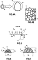
- Figure 4A shows an exemplary polymer microsphere.
- the polymer microsphere may be configured to expand when heated due to internal pressure of a gas enclosed therein.
- the microsphere may have a size (for example a diameter), prior to expansion, of equal to or greater than 5 ⁇ m and equal to or less than 40 ⁇ m, or even equal to or greater than 6 ⁇ m and equal to or less than 40 ⁇ m, or even equal to or greater than 6 ⁇ m and equal to or less than 9 ⁇ m.
- the microsphere is shown prior to expansion at 41 and is shown in an expanded state at 45. Accordingly, prior to expansion, the microsphere is referred to as "expandable”, and is referred to as "expanded" subsequent to expansion.
- an expandable microsphere 41 is sold under the name "Expancel" by Nouryon.
- the microsphere may be substantially hollow, for example, and may include a shell 43 made of thermoplastic polymer to enclose the gas. Prior to expansion, the shell 43 may, for example, have a thickness of approximately 2 ⁇ m. Subsequent to expansion, the shell 43 may, for example, have a thickness of less than 2 ⁇ m.
- Heating the microsphere may allow for internal pressure within the microsphere to deform the shell 43 plastically.
- expanding the expandable polymer microsphere may include heating the expandable polymer microsphere to a temperature at which the shell is plastically deformable from the internal pressure within the expandable polymer microsphere.
- the expandable polymer microsphere may reach a temperature, for example, of equal to or greater than 80°C and equal to or less than 200°C, or equal to or greater than 100°C and equal to or less than 150°C, or equal to or greater than 80°C and equal to or less than 135 °C. Heating will be discussed in greater detail with regard to Figure 5 .
- At least one expandable polymer microsphere may undergo, for example, an increase in volume equal to or less than 200-fold, or a 38-fold increase in volume, as it becomes an expanded polymer microsphere.
- Figure 4B shows a schematic representation of an exemplary liquid suspension 5.
- the liquid suspension 5 may be for coating at least a portion of a blade body.
- the liquid suspension 5 includes a liquid uncured polymer precursor 51 and expandable polymer microspheres 41. At least one of the expandable polymer microspheres 41 of the liquid suspension 5 may be an expandable polymer microsphere 41 as described earlier herein, for example.
- the liquid suspension 5 may include equal to or greater than 0.1% and equal to or less than 30 % expandable polymer microspheres 41 by mass, or even equal to or greater than 5 % and equal to or less than 15 % expandable polymer microspheres 41 by mass.
- the liquid uncured polymer precursor 51 may form the remainder of the liquid suspension 5.
- the liquid suspension 5 may be manufactured by mixing the liquid uncured polymer precursor 51 and expandable polymer microspheres 41 together.
- the liquid uncured polymer precursor 51 may be UV-curable, and may even include a UV-curing initiator, for example.
- Non-limiting examples of such liquid uncured polymer precursors include 758-series "Solarez” UV-cure products offered by Wahoo International.
- Thermal-curable and/or infrared-curable liquid uncured polymer precursors are also contemplated, as are liquid uncured polymer precursors which cure through atmospheric exposure, for example.
- the liquid uncured polymer precursor 51 may include cyanoacrylate, acrylated epoxy, acrylated polyester, acrylated silicon, or methacrylate ester, for example.
- the liquid uncured polymer precursor 51 may, for example, be configured to remain at least partially uncured when heated to the temperatures at which the microspheres are heated to transform them from expandable polymer microspheres 41 to expanded polymer microspheres (for example during heating) for a duration sufficient for such transformation of the microspheres to occur.
- expansion of the expandable microspheres within a given deposit may occur over a period of 20 ms (millliseconds) or less, whereas complete curing of the liquid uncured polymer precursor in the given deposit may occur over a period of approximately one second or more.
- curing of the liquid uncured polymer precursor may be triggered at higher energy levels and/or temperatures than are necessary for causing expansion of the expandable microspheres.
- the process S1 for fabricating the razor blade may also include curing S40 the expanded deposit thereby forming an expanded coating structure including a cured polymer matrix containing one or more expanded microspheres.
- Curing S40 may allow at least a portion of the uncured liquid polymer precursor, contained in the liquid suspension previously deposited onto the blade body and present in the expanded coating structure after expanding S30, to be transformed into a cured polymer matrix containing the one or more expanded microspheres, for example.
- expandable polymer microsphere is still used to refer to microspheres which, prior to curing, could have been made to expand, thereby transforming into expanded polymer microspheres.
- curing S40 may include exposing the liquid uncured polymer precursor (or UV-curable initiator thereof, when present) to ultraviolet or near-ultraviolet electromagnetic radiation.
- the electromagnetic radiation used during curing S40 may have a wavelength of 405 nm or less. This may allow depositing S20 and expanding S30 to be conducted in visible light prior to curing S40, for example.
- the electromagnetic radiation used in curing the liquid uncured polymer precursor may be provided by a light-emitting diode and/or a laser.
- curing S40 may include exposing the cyanoacrylate to moisture.
- the expandable polymer microspheres provided during depositing S20 may allow for formation of the expanded coating structure to be at least partially dissociated from deposition of its/their constituent materials. This may, for example, allow for reductions in fabrication cost and/or time and/or complexity for the razor blade. For example, depositing S20 a relatively thin deposit and expanding S30 the expandable polymer microspheres therein to obtain an expanded coating structure of a desired thickness may be cheaper/simpler/faster than forming a deposit whose thickness is nearer to that of the desired protrusion thickness without expansion.
- depositing S20 a relatively uniform deposit on the blade body and providing local variations in expansion during expanding S30 to obtain a desired expanded coating structure pattern/geometry may be simpler/more precise than depositing a relatively non-uniform deposit to obtain the desired protrusion pattern/geometry without expansion. Either or both of these may also translate to reductions in cost, for example. These benefits may be seen even when the process S1 for fabricating the razor blade includes curing S40.
- Figure 5 shows a schematic view of an exemplary razor blade 1"' according to an example of the present disclosure during expanding by heating.
- the razor blade 1"' shown being fabricated in Figure 5 includes a double-edged blade body 11 (such as those available for so-called “safety” shavers).
- the razor blade 1"' is shown "edge-on” relative to a cutting edge of a first cutting edge portion 13 of the blade body 11.
- the first cutting edge portion of the blade body 11 is connected to a second cutting edge portion of the blade body 11 by way of a first flat portion extending therebetween which is monolithically constructed with the first and second cutting edge portions.
- Each cutting edge portion of the blade body includes its own cutting edge 13A.
- the razor blade 1''' shown being fabricated in Figure 5 will include multiple discrete expanded coating structures. Accordingly, the liquid suspension has been provided as multiple discrete deposits, 2, 22. Expansion has been performed sequentially from the left side of Figure 5 to the right side of Figure 5 . On the right side of Figure 5 , at formation site 21, an unexpanded deposit 2 is shown prior to expanding and transforming into an expanded deposit. Multiple discrete expanded deposits 22 are shown to the left of the formation site 21, near the center of Figure 5 .
- the expanded deposits 22 will be transformed into expanded coating structures 23 when the liquid uncured polymer precursor contained therein is cured to form a cured polymer matrix.
- the geometry and/or quantity of expanded coating structures 23 on a given razor blade 1''' may be determined during deposition of the unexpanded deposit(s) 2, and/or during expansion of the expandable polymer microspheres, for example. This possibility will be discussed in greater detail later.
- a heating device 6 may be provided, which is configured to provide energy to heat the deposit(s) 2 on the blade body 11 to form the expanded polymer microspheres of the expanded coating structure 23.
- the heating device 6 may, for example, include a heating element configured to be arranged in close proximity to the unexpanded deposit(s) 2.
- the heating element may be made to contact the blade body 11 and/or unexpanded deposit 2 so as to conduct heat thereto.
- the heating device 6 may include an electromagnetic radiation source 61, for example.
- the electromagnetic radiation source 61 may emit a beam 63 of electromagnetic radiation to heat the expandable polymer microspheres, for example.
- the beam 63 may include infrared radiation, for example.
- the electromagnetic radiation source 61 may, for example, include a laser. This heating device may be used in all examples disclosed herein. Although radiative heating is described, convective and conductive heating are also contemplated.
- the heating device 6 may be provided to heat the unexpanded deposit 2 directly (for example by exposing the unexpanded deposit to the beam 63, when present) and/or indirectly (for example by exposing the blade body 11 to the beam 63, when present, so as to transfer heat into the unexpanded deposit).
- indirect heating may allow for heating to be provided at a higher intensity than may be suitable for generating the expanded polymer microspheres of the expanded coating structure. Additionally or alternatively, for example, this may allow heat transfer characteristics of the substrate of the unexpanded deposit 2 (for example the blade body 11) to contribute to controlling formation of the expanded polymer microspheres and/or the geometry of the resulting expanded coating structure(s).
- heat may be delivered to a different side of the blade body 11 from the unexpanded deposit 2.
- the beam 63 is focused onto an opposite surface of the blade body 11 from the unexpanded deposit 2.
- the beam 63 is directed onto the bottom surface of the blade body 11. Heat may be transferred into the unexpanded deposit 2 at the formation site 21, opposite from the beam 63, from the side of the unexpanded deposit's substrate (in this case the side of the unexpanded deposit 2 that is nearest the blade body 11).
- Figure 6 shows a cross section of an exemplary unexpanded deposit 2.
- the unexpanded deposit 2 may be, for example, the unexpanded deposit 2 provided at the formation site 21 in Figure 5 .
- the unexpanded deposit 2 may have a maximum thickness Hu of equal to or greater than 20 ⁇ m and equal to or less than 200 ⁇ m, as measured normal to the blade body (for example normal to the top surface 17 of the blade body).
- the unexpanded deposit 2 may have a width Wu of equal to or greater than 100 ⁇ m and equal to or less than 850 ⁇ m, as measured parallel to the top surface 17 of the blade body (for example along the length of the blade body, parallel to the cutting edge, and/or along the width of the blade body, parallel to the top surface 17 of the blade body and perpendicular to the cutting edge).
- unexpanded deposit 2 is shown as being substantially semicircular in profile, it is also contemplated to provide a deposit that is substantially flat in profile.
- the mass fractions of expandable polymer microspheres 41 and liquid uncured polymer precursor 51 of the unexpanded deposit 2 may correspond substantially to those of the liquid suspension provided during depositing S20 in Figure 3 .
- Figure 7 shows an exemplary expanded coating structure 23 obtainable from the unexpanded deposit 2 of Figure 6 after expansion of the expandable polymer microspheres 41 therein to create expanded polymer microspheres 45 (and curing of liquid uncured polymer precursor 51 of the resulting expanded protrusion, when required).
- the expanded polymer microspheres 45 may be contained in a cured polymer matrix 53 obtainable by curing the liquid uncured polymer precursor 51 provided in the unexpanded deposit 2 of Figure 6 .
- the mass fractions of expanded polymer microspheres 45 and cured polymer matrix 53 in the expanded coating structure 23 may correspond to the mass fractions of expandable polymer microspheres 41 and liquid uncured polymer precursor 51 in the unexpanded deposit 2, it may be understood (and it is contemplated) to provide an expanded coating structure which contains a mixture of expandable and expanded microspheres, for example by avoiding heating of a given region of the deposit prior to expansion of all of the expandable microspheres located therein.
- expansion of the expandable polymer microspheres may cause the expanded coating structure 23 to have a maximum thickness He of equal to or greater than 100 ⁇ m and equal to or less than 500 ⁇ m, or even equal to or greater than 120 ⁇ m and equal to or less than 300 ⁇ m.
- the expanded coating structure 23 may have a width We, of equal to or greater than 100 ⁇ m and equal to or less than 2000 ⁇ m, or even equal to or greater than 550 ⁇ m and equal to or less than 1000 ⁇ m, for example.
- the resulting expanded coating structure 23 is shown as having a profile that is substantially similar in shape to that of the corresponding unexpanded deposit 2 from which it was obtained, it is understood that an expanded coating structure may be provided with a substantially different profile to the corresponding unexpanded deposit, for example by providing variations in heating.
- the expanded coating structure 23 is shown as being its widest at its interface with the top surface 17 of the blade body, it may be understood that, depending on how expanding S30 progresses, the maximum width We may occur at a distance from the top surface 17.
- the geometry and/or quantity of expanded coating structures 23 on a given razor blade may additionally or alternatively be determined during deposition of the deposit 2, for example.
- the liquid suspension may be deposited multiple distinct locations on the blade body, so that formation of the expanded coating structures by expanding S30 the expandable microsphere(s) may be substantially constrained to these locations.
- so-called "inkjet technology” in which a jet of material which may or may not be ink is projected onto a target material
- the placement (on the blade body) and/or geometry of the deposit formed by depositing S20 may help to determine the placement and/or geometry of the expanded coating structure that may be obtainable by expanding S30.
- the interface between the expanded coating structure and the blade body may correspond substantially to the geometry of the interface between the blade body and the deposit from which the expanded coating structure was formed.
- Figure 8 shows a top view of one of the razor blades 1" of Figure 2B (normal to the top surface 17 of the blade body 11), subsequent to depositing S20, expanding S30, and curing S40.
- Depositing S20 was performed onto the blade support 33 presenting the top surface 17 of the blade body 11, yielding multiple discrete unexpanded deposits, as seen with Figure 5 . It may be understood, however, that a single, continuous unexpanded deposit may also be suitable for this razor blade 1".
- the razor blade 1" is shown subsequent to assembly of the cutting edge portion 13 to the blade support, it may be understood that such assembly may be performed subsequent to depositing S20, expanding S30 and curing S40.
- the razor blade 1" in Figure 8 is shown as having multiple discrete expanded coating structures 23, which each have substantially rectangular “footprints" (areas of contact with the blade body 11) as a result of them being formed from deposits that were substantially rectangular in shape on the blade body 11.
- Non-rectangular footprints are also contemplated.
- Figure 9 shows a top view, edge-on view, and side view (orthogonal to the top and edge-on views) of a razor blade 1* as a one-piece blade body, called a "bent blade".
- the razor blade 1* shown in Figure 9 has a cutting edge portion 13 which is monolithically constructed with a blade support 33.
- the first flat portion 12A extends from the cutting edge portion 13 as seen in Figure 1A , but is prolonged by a second flat portion 12B extending from an intermediate portion 12' linking the second flat portion 12B to the base portion 30.
- the razor blade 1* shown in Figure 9 includes a plurality of expanded coating structures 23 obtained by selectively expanding non-contiguous regions of a shared unexpanded deposit 2. Accordingly, the remnants of the unexpanded deposit 2 are shown in Figure 9 as extending between adjacent expanded coating structures 23.
- By forming multiple expanded coating structures 23 from a shared unexpanded deposit 2 it may be possible to reduce the time required to perform depositing of the liquid suspension on the blade body 11, for example. Additionally or alternatively, for example, unexpanded regions of a shared deposit 2 from which multiple expanded coating structure(s) 23 may contribute to the strength of the connections between these expanded coating structures and the blade body 11.
- the expanded coating structures 23 in Figures 8 & 9 are shown as having substantially equivalent gaps G with respect to the cutting edge 13 as each other, it is also contemplated for multiple expanded coating structures 23 within a given plurality of expanded coating structures to have different gaps G from one another. Likewise, as seen in Figure 10 , the gap G may vary along the length of the blade body 11 even when a continuous expanded coating structure 23 is provided.
- Figure 10 shows one of the razor blades 1' of Figure 2A , and includes top, side, and edge-on views as seen in Figure 9 .
- the razor blade 1' shown in Figure 10 includes a curvilinear expanded coating structure 23 obtained by uniformly expanding a continuous curvilinear deposit arranged along the cutting edge portion 13 of the blade body 11, and the cutting edge portion 13 is mounted to a blade support 33.
- the gap G separating the expanded coating structure 23 from the cutting edge of the cutting edge portion 13 is seen to vary along the length direction of the blade body 11 (parallel to the cutting edge).
- a cutting edge portion of a double-edged blade body was provided, measuring 0.1 mm thick, and made of stainless steel.
- Pad printing was used for depositing the first liquid suspension onto a top surface of the cutting edge portion of the blade body such that a continuous linear deposit was arranged substantially parallel to the cutting edge of the blade body.
- the deposit was observed to have a width of 650-850 ⁇ m as measured parallel to the top surface of the blade body, and had a thickness of 20-200 ⁇ m as measured perpendicular to the top surface of the blade body.
- An 80 watt beam of infrared light was used for expanding the expandable microspheres of the deposits.
- the beam had a wavelength of 1064 nm and was shone onto blade body from an infrared laser at a plurality of locations on the bottom surface thereof.
- Each location illuminated by the beam was circular with a diameter of 0.6 mm, and centered on the opposite side of the blade body from a deposit in the first plurality of deposits.
- Each location was illuminated for 5 ms (milliseconds), causing heating of the blade body and of the corresponding deposit until expandable microspheres of the exposed portion of the deposit reached the prescribed expansion temperature range indicated on the product datasheet (approximately 106-137 °C).
- the resulting expanded deposits corresponding to the portions of the unexpanded deposit subjected to expansion, had a substantially semi-circular cross-section with a diameter of 550-1000 ⁇ m and a thickness of 120-300 ⁇ m.
- Digital microscopic analysis of a sample of 30 expanded polymer microspheres in these expanded coating structures revealed diameters in the range of 10-21 ⁇ m as measured using standard microscopy techniques, corresponding to these microspheres increasing in volume 13-43 fold while expanding from expandable polymer microspheres to expanded polymer microspheres.
- a razor blade was prepared as described in the first non-limiting example, and the expanded coating structures thereof were subjected to curing by exposure to a 0.5-watt beam from a light-emitting diode configured to emit near ultraviolet radiation at a wavelength of 405 nm.
- Exposure to the beam lasted 5 seconds, causing transformation of the liquid uncured polymer precursor remaining from the deposits from which the expanded coating structures were formed into a cured polymer matrix, as confirmed by digital microscopic analysis of 4 protrusions of the expanded coating structure subsequent to curing in this manner.
- a cutting edge portion of blade body was provided as described in the first non-limiting example, and the liquid suspension was deposited onto the top surface of the cutting edge portion of the blade body in the same manner as described with regard to the first non-limiting example.
- the deposit had similar dimensions to those of the first non-limiting example.
- the blade body and associated unexpanded deposit were heated in an oven until expandable microspheres of the deposit reached the prescribed temperature range indicated on the product datasheet (approximately 95-120°C) to transform the unexpanded deposit into an expanded deposit.
- the resulting expanded deposit was then cured as described with respect to the second non-limiting example to yield an expanded coating structure.
Landscapes
- Engineering & Computer Science (AREA)
- Life Sciences & Earth Sciences (AREA)
- Forests & Forestry (AREA)
- Mechanical Engineering (AREA)
- Chemical & Material Sciences (AREA)
- Wood Science & Technology (AREA)
- Materials Engineering (AREA)
- Organic Chemistry (AREA)
- Health & Medical Sciences (AREA)
- Chemical Kinetics & Catalysis (AREA)
- Medicinal Chemistry (AREA)
- Polymers & Plastics (AREA)
- Compositions Of Macromolecular Compounds (AREA)
- Manufacture Of Porous Articles, And Recovery And Treatment Of Waste Products (AREA)
- Surgical Instruments (AREA)
Abstract
Description
- The present disclosure relates to the field of shaving and in particular to razor blades.
- It is known from United States Patent Application n°
US20160297087A1 to print an object onto a blade body of a razor blade, and from United States Patent Application n°US20180001497A1 to print a lubricious material on a blade body of a razor blade. However, printing large amounts of material onto a blade may be quite time-consuming and/or expensive and/or cumbersome. - According to an example of the present disclosure, a razor blade is provided. The razor blade includes a blade body and an expanded coating structure. The expanded coating structure is arranged on a surface of the blade body so as to cover the blade body at least partially. The expanded coating structure includes one or more expanded polymer microspheres. At least one of the one or more expanded polymer microspheres includes a gas encapsulated within a hollow thermoplastic polymer shell.
- The blade may thus be provided with one or more protruding structures which are relatively simple and/or rapid and/or inexpensive to produce, for example.
- The expanded coating structure may include a cured polymer matrix containing the one or more expanded polymer microspheres.
- The expanded coating structure may include equal to or greater than 0.1% and equal to or less than 30% expanded and/or expandable polymer microspheres by mass, specifically equal to or greater than 5% and equal to or less than 15% expanded and/or expandable polymer microspheres by mass, and may include a polymer matrix forming the remainder.
- The shell of at least one of the one or more expanded polymer microspheres may have a thickness less than 2 µm (micrometers).
- The expanded coating structure may present a maximum thickness, as measured normal to the surface of the blade body, equal to or greater than 120 µm and equal to or less than 500 µm, specifically equal to or greater than 120 µm and equal to or less than 300 µm.
- The expanded coating structure may present a width, as measured parallel to the surface of the blade body, equal to or greater than 100 µm and equal to or less than 2000 µm, specifically equal to or greater than 550 µm and equal to or less than 1000 µm.
- At least one of the one or more expanded polymer microspheres may have a diameter of equal to or greater than 6 µm and equal to or less than 130 µm.
- Additionally or alternatively, a skincare device may be provided according to an example of the present disclosure. The skincare device may include a razor blade as described earlier herein.
- Additionally or alternatively, according to an example of the present disclosure, a liquid suspension may be provided for coating a blade body. The liquid suspension may include expandable polymer microspheres dispersed in a liquid uncured polymer precursor. At least one of the expandable microspheres may include a gas encapsulated in a hollow thermoplastic polymer shell. The liquid uncured polymer precursor may be configured to remain uncured during expansion of the expandable polymer microspheres.
- The liquid suspension may allow a deposit containing expandable polymer microspheres to be provided on the blade body through liquid deposition techniques, for example.
- The liquid suspension may include equal to or greater than 0.1% and equal to or less than 30% expandable polymer microspheres by mass, specifically equal to or greater than 5% and equal to or less than 15% expandable polymer microspheres by mass, and liquid uncured polymer precursor forming the remainder.
- At least one of the expandable polymer microspheres may have a diameter equal to or greater than 5 µm and equal to or less than 40 µm, specifically equal to or greater than 6 µm and equal to or less than 40 µm, specifically equal to or greater than 6 µm and equal to or less than 9 µm.
- The liquid uncured polymer precursor may be UV-curable.
- The liquid uncured polymer precursor may include a UV-curable initiator.
- Additionally or alternatively, according to an example of the present disclosure, a process may be provided. The process may be a process for fabrication of a razor blade as described earlier herein. The process may include providing a blade body. The process may include depositing a liquid suspension on a surface of the blade body to obtain a deposit. The liquid suspension may be a liquid suspension as described earlier herein. The process may include expanding one or more of the expandable polymer microspheres in the deposit to obtain an expanded deposit including one or more expanded polymer microspheres arranged on the surface of the blade body.
- The process may allow for shaping of the structure(s) on the blade body to be at least partially dissociated from provision of the material from which it is/they are constructed.
- The step of expanding one or more of the expandable polymer microspheres may include heating one or more expandable polymer microspheres to a temperature at which the shell is plastically deformable under pressure of the gas encapsulated therein so as to achieve an increase in volume.
- The step of expanding one or more of expandable polymer microspheres may include heating the one or more expandable polymer microspheres to a temperature equal to or greater than 80°C (degree Celsius) and equal to or less than 200°C, specifically equal to or greater than 100°C and equal to or less than 150°C, specifically equal to or greater than 80°C and equal to or less than 135°C.
- At least one expandable polymer microsphere may undergo an increase in volume that is equal to or less than 200-fold during the step of expanding at one or more of the expandable polymer microspheres, specifically an equal to or less than 38-fold increase in volume during the step of expanding one or more of the expandable polymer microspheres.
- The process may comprise curing the liquid uncured polymer precursor subsequent to the step of expanding one or more of the expandable polymer microspheres, to obtain a cured polymer matrix containing one or more expanded polymer microspheres.
- The curing step may include exposing the expanded deposit to electromagnetic radiation.
- The electromagnetic radiation used in the curing step may have a wavelength of 405 nm (nanometer) or less.
- Additionally or alternatively, a process of fabricating a skincare device as described earlier herein may be provided. The process may include attaching a razor blade as described earlier herein to a cartridge.
- As used in this disclosure and the appended claims, the term "blade body" may be understood as a blade element including a cutting edge portion and a first flat portion extending from the cutting edge portion.
- The blade body may include two cutting edge portions - a configuration also referred to as a "double-edged blade," in which the first flat portion may extend from a first of the cutting edge portions to a second of the cutting edge portions. Alternatively to the double-edged blade, the blade body may include a base portion connected to the blade element such that the first flat portion is intermediate to the cutting edge portion and the base portion.
- The base portion and the first flat portion may be connected to each other by being monolithically constructed with one another, or may be assembled to one another.
- The base portion may form a blade support, and may include a second flat portion which may be intermediate the base portion and the cutting edge portion. The second flat portion may extend at an angle with respect to the base portion, so as to be arranged obliquely or perpendicularly thereto. The second flat portion and the base portion may be built together monolithically.
- The second flat portion may be connected to the first flat portion such that, during shaving, the second flat portion is arranged towards the skin with respect to the first flat portion. Alternatively, the second flat portion may be connected to the first flat portion such that, during shaving, the first flat portion is arranged towards the skin and the second flat portion faces away from the skin. Alternatively, the first flat portion and the second flat portion may be connected to each other such that the second flat portion prolongs the first flat portion - a configuration also referred to as an integrally-built "bent blade," in which the blade support and the cutting edge portion are monolithically constructed with one another.
- When a given skincare device includes multiple blade bodies, two or more of said multiple blade bodies may have an identical configuration to one another, or may have different configurations from one another.
- The disclosure may be more completely understood in consideration of the following detailed description of aspects of the disclosure in connection with the accompanying drawings, in which:
-
Figure 1A shows an exemplary razor blade having an exemplary continuous expanded coating structure. -
Figure 1B shows a cross-sectional view of the razor blade ofFigure 1A along line B-B. -
Figure 2A shows a cross-sectional view of an exemplary shaving cartridge. -
Figure 2B shows a cross-sectional view of an exemplary shaving cartridge. -
Figure 3 shows a process flow chart for an exemplary process for fabricating a skincare device. -
Figure 4A shows a cutaway view of an exemplary microsphere in both an unexpanded state (left) and expanded state (right). -
Figure 4B shows an exemplary liquid suspension. -
Figure 5 shows an exemplary step of an exemplary process for fabricating a razor blade. -
Figure 6 shows a cross-sectional view of an exemplary deposit as seen along line A-A ofFigure 5 . -
Figure 7 shows a cross-sectional view of an exemplary expanded coating structure as seen along line C-C ofFigure 5 . -
Figure 8 shows a top view of an exemplary razor blade having discrete expanded coating structures. -
Figure 9 shows an exemplary razor blade having multiple expanded coating structures, including a side view, an edge-on view, and a top view. -
Figure 10 shows an exemplary razor blade having a continuous expanded coating structure in curvilinear shape, including a side view, an edge-on view, and a top view. - The term "exemplary" is used in the sense of "example," rather than "ideal." While aspects of the disclosure are amenable to various modifications and alternative forms, specifics thereof have been shown by way of example in the drawings and will be described in detail. It should be understood, however, that the intention is not to limit aspects of the disclosure to the particular embodiment(s) described. On the contrary, the intention of this disclosure is to cover all modifications, equivalents, and alternatives falling within the scope of the disclosure.
- As used in this disclosure and the appended claims, the singular forms "a", "an", and "the" include plural referents unless the content clearly dictates otherwise. As used in this disclosure and the appended claims, the term "or" is generally employed in its sense including "and/or" unless the content clearly dictates otherwise.
- The following detailed description should be read with reference to the drawings. The detailed description and the drawings, which are not necessarily to scale, depict illustrative aspects and are not intended to limit the scope of the disclosure. The illustrative aspects depicted are intended only as exemplary.
-
Figure 1A shows a single-edgedrazor blade 1 according to an example of the present disclosure, as seen normal or oblique to atop surface 17 of ablade body 11 of therazor blade 1. During shaving with therazor blade 1, thetop surface 17 of theblade body 11 is arranged towards the skin. Thetop surface 17 may be flat. - The
blade body 11 of therazor blade 1 presents a firstflat portion 12A extending from acutting edge portion 13. Thecutting edge portion 13 presents acutting edge 13A. Theblade body 11 may be metallic (for example stainless steel) with a thickness of approximately equal to or greater than 0.05 mm (millimeter) and equal to or less than 0.1 mm, as measured between opposite surfaces of the firstflat portion 12A. - A continuous expanded
coating structure 23 is disposed on theblade body 11. The expandedcoating structure 23 includes one or more expanded polymer microspheres. The expanded polymer microspheres may include a gas encapsulated within a hollow thermoplastic polymer shell. During shaving, the expandedcoating structure 23 and thecutting edge 13A of thecutting edge portion 13 may contact the skin concurrently with one another. Such contact by the expandedcoating structure 23 may help to support the skin in a vicinity of thecutting edge 13A of thecutting edge portion 13, leading to improved shaving performance and/or sensation for the user during shaving. - For example, as the expanded
coating structure 23 contacts the skin, the skin may become tauter in a vicinity of thecutting edge 13A of thecutting edge portion 13. This may, for example, increase smoothness of contact between the skin and thecutting edge 13A of thecutting edge portion 13. - Additionally or alternatively, for example, the expanded
coating structure 23 may allow a portion of the contact force of therazor blade 1 to bypass thecutting edge 13A of thecutting edge portion 13 during transmission to the skin. This may, for example, reduce contact pressure between the skin and thecutting edge 13A of thecutting edge portion 13. - Additionally or alternatively, for example, the expanded
coating structure 23 may reduce bulging of the skin towards theblade body 11 in a vicinity of thecutting edge portion 13. This may, for example, allow for a shaver to be perceived on the skin as being less aggressive than a shaver of comparable blade exposure (cutting edge exposure) which lacked expanded coating structures. - Additionally or alternatively, for example, the expanded
coating structure 23 may reduce friction between thecutting edge 13A of thecutting edge portion 13 and the skin. This may, for example, facilitate maneuvering of therazor blade 1 on the skin. - Additionally or alternatively, for example, the expanded
coating structure 23 may reduce irritation and/or a risk of cutting the skin during shaving. - The expanded
coating structure 23 may be provided on theblade body 11 so as to be separated from thecutting edge 13A of thecutting edge portion 13 by a gap G. -
Figure 1B shows therazor blade 1 ofFigure 1A in cross-section along line B-B. The gap G may, for example, be measured as a distance between the expandedcoating structure 23 to an orthogonal projection of thecutting edge 13A on a plane in which thetop surface 17 of theblade body 11 lies, as measured in said plane from said expanded coating structure to said orthogonal projection. For example, the gap G may measure 1 mm or less. For example, when theblade body 11 has a width, as measured perpendicular to thecutting edge 13A of thecutting edge portion 13 and parallel to thetop surface 17 of theblade body 11, of 1.5 mm, the gap G may measure 0.5 mm. - The first
flat portion 12A and cuttingedge portion 13 are monolithically constructed with one another. -
Figure 2A shows a cross-sectional view of a skincare device 3, in particular a shavingcartridge 31, according to an example of the present disclosure, in contact withskin 0 during shaving. - The skincare device 3 may include one or more razor blades, of which at least one may be a razor blade 1' according to an example of the present disclosure. As seen with the
razor blade 1 ofFigures 1A-1B , each such razor blade 1' inFigure 2A includes ablade body 11 and an expandedcoating structure 23 disposed on thecutting edge portion 13 thereof, such that the expandedcoating structure 23 and the cutting edge of thecutting edge portion 13 contact theskin 0 concurrently during shaving. The gap G separating thecutting edge 13A of thecutting edge portion 13 from thecoating structure 23 may be measured in the same manner as described previously. - In contrast with
Figures 1A-1B , in each of the razor blades 1' inFigure 2A , theblade body 11 includes a secondflat portion 12B. The firstflat portion 12A of theblade body 11 and the secondflat portion 12B of theblade body 11 are assembled together. Theblade body 11 additionally includes abase portion 30 which extends from the secondflat portion 12B such that the secondflat portion 12B is intermediate thecutting edge portion 13 and thebase portion 30. - The second
flat portion 12B and thebase portion 30 form ablade support 33, and may be monolithically constructed with one another. - The second
flat portion 12B is arranged to extend at an angle, obliquely with respect to thebase portion 30, so that thecutting edge 13A of the cutting edge portion 13 (connected thereto via the firstflat portion 12A) and the expandedcoating structure 23 may be brought to bear on theskin 0 concurrently during shaving. - When the skincare device 3 is maneuvered on the
skin 0 of a user during shaving, (during normal intended use of the skincare device 3), the cutting edge(s) 13A of the cutting edge portion(s) 13 of the razor blade(s) 1' contact(s) the skin 0 (possibly in combination with other organic material such as hair) such that the expanded coating structure(s) 23 disposed on the blade body/bodies 11 thereof is/are arranged towards theskin 0 so as to contact theskin 0 as theskin 0 contacts the cutting edge(s) 13A. - The width We of a given expanded
coating structure 23 may be measured, for example, along thetop surface 17 of theblade body 11, for example parallel to thecutting edge 13A of thecutting edge portion 13 of the razor blade 1', or perpendicular to a projection of thecutting edge 13A of thecutting edge portion 13 to thetop surface 17 of theblade body 11 which is orthogonal to the top surface of theblade body 11. The height He of a given expandedcoating structure 23 may be measured, for example, normal to thetop surface 17 of theblade body 11. - As mentioned above, the expanded
coating structure 23 may include one or more expandedpolymer microspheres 45, for example. The expandedcoating structure 23 may also include a curedpolymer matrix 53 in which the expandedpolymer microspheres 45 are contained, for example. The expandedpolymer microspheres 45 will be discussed in greater detail with regard toFigure 4A . The expandedcoating structure 23 may, for example, include equal to or greater than 0.1% and equal to or less than 30% expandedpolymer microspheres 45 by mass, with the curedpolymer matrix 53 forming the remainder, or even equal to or greater than 5% and equal to or less than 15% expanded polymer microspheres by mass, with the cured polymer matrix forming the remainder. The expandedcoating structure 23 will be discussed in greater detail with regard toFigure 7 . -
Figure 2B shows a cross-sectional view of a shaving cartridge 3', similar to the cartridge 3 shown inFigure 2A . In contrast with the cartridge 3 shown inFigure 2A , which includes five exemplary razor blades 1', the cartridge 3' shown inFigure 2B includes fourexemplary razor blades 1". - In contrast with the exemplary razor blades 1' shown in
Figure 2A , in which thecutting edge portion 13 and the firstflat portion 12A of theblade body 11 separates theskin 0 from theblade support 33, each of theexemplary razor blades 1" shown inFigure 2B has ablade body 11 of which thecutting edge portion 13 and the firstflat portion 12A are mounted on ablade support 33 such that theblade support 33 is arranged towards theskin 0 with respect to thecutting edge portion 13 and firstflat portion 12A during shaving. As withFigure 2A , theblade support 33 includes abase portion 30 of theblade body 11 and a secondflat portion 12B of theblade body 11 arranged intermediate thecutting edge portion 13 and thebase portion 30. - In contrast with
Figure 2A , in which thetop surface 17 is presented on thecutting edge portion 13 and/or on the firstflat portion 12A, inFigure 2B , thetop surface 17 of theblade body 11 is presented on the secondflat portion 12B of theblade body 11. The expandedcoating structure 23 is therefore provided on theblade support 33, and the width We of the expandedcoating structure 23, thickness He of the expandedcoating structure 23 and gap G separating the expanded coating structure from the cutting edge are measured as described previously, albeit using thetop surface 17 as presented by the secondflat portion 12B of theblade support 33. - As with
Figure 2A , inFigure 2B , the secondflat portion 12B is angled obliquely with respect to thebase portion 30 such that thecutting edge 13A of thecutting edge portion 13 and the expandedcoating structure 23 can be brought to bear concurrently with one another on theskin 0 during shaving. Additionally, as an option visible inFigure 2B , the secondflat portion 12B of theblade body 11 may be brought to bear on theskin 0 during shaving. When multiple razor blades according to the present disclosure are provided to a skincare device, it may be understood that two or more razor blades may be provided according to the same example of the present disclosure and/or that two or more razor blades may be provided according to different examples of the present disclosure. -
Figure 3 shows a process S100 by which a skincare device, such as the skincare device 3 shown inFigure 2A or the skincare device 3' shown inFigure 2B , may be fabricated. The process S100 for fabricating a skincare device may include providing a razor blade according to an example of the present disclosure and arranging S99 the base portion of blade body of the razor blade within a razor cartridge. Arranging S99 the base portion of the blade body of the razor blade within the cartridge may be performed in a conventional manner, for example by providing the cartridge with one or more slots and arranging the base portion(s) of the corresponding blade body/ies within the slot(s). - As will be discussed in greater detail with regard to
Figure 9 , the cutting edge portion of the blade body may alternatively be monolithically constructed with the blade support, rather than assembled together as described earlier herein. For example, the second flat portion may be made to extend monolithically from the first flat portion away from the cutting edge of the cutting edge portion. In this case, the top surface of the blade body may be presented by both the first flat portion and the second flat portion. - When the blade support and the cutting edge portion are monolithically constructed with one another, the step of attaching S99 the cutting edge portion to the razor cartridge may be performed simultaneously with attaching the blade support to the cartridge. When the blade support and the cutting edge portion are not monolithically constructed with one another, the step of attaching S99 the cutting edge portion to the cartridge may be performed simultaneously with attaching the blade support to the razor cartridge (for example by attaching the blade support to the razor cartridge subsequent to assembling the cutting edge portion to the blade support), or may be performed sequentially with attaching the blade support to the razor cartridge (for example by assembling the cutting edge portion to the blade support subsequent to attaching the blade support to the razor cartridge).
- As a non-limiting example, the razor blade may be provided by performing a process S1 of fabricating a razor blade. The process S1 for fabricating a razor blade may include providing S10 a blade body, followed by depositing S20 a liquid suspension on a surface of the blade body to obtain a deposit containing one or more expandable polymer microspheres, followed by expanding S30 one or more of the expandable polymer microspheres dispersed in the deposit to obtain an expanded deposit containing one or more expanded polymer microspheres. The liquid deposit may be provided as a liquid suspension of expandable polymer microspheres dispersed in a liquid uncured polymer precursor, which may be configured to remain uncured during expansion of the expandable polymer microspheres. The process S1 may also include a step of curing S40 the liquid uncured polymer precursor, subsequent to expanding S30 the one or more expandable polymer microspheres, to obtain a cured polymer matrix in which the expanded polymer microspheres are contained.
-
Figure 4A shows an exemplary polymer microsphere. The polymer microsphere may be configured to expand when heated due to internal pressure of a gas enclosed therein. For example, the microsphere may have a size (for example a diameter), prior to expansion, of equal to or greater than 5 µm and equal to or less than 40 µm, or even equal to or greater than 6 µm and equal to or less than 40 µm, or even equal to or greater than 6 µm and equal to or less than 9 µm. The microsphere is shown prior to expansion at 41 and is shown in an expanded state at 45. Accordingly, prior to expansion, the microsphere is referred to as "expandable", and is referred to as "expanded" subsequent to expansion. One example of anexpandable microsphere 41 is sold under the name "Expancel" by Nouryon. - The microsphere may be substantially hollow, for example, and may include a
shell 43 made of thermoplastic polymer to enclose the gas. Prior to expansion, theshell 43 may, for example, have a thickness of approximately 2 µm. Subsequent to expansion, theshell 43 may, for example, have a thickness of less than 2 µm. - Heating the microsphere may allow for internal pressure within the microsphere to deform the
shell 43 plastically. Accordingly, expanding the expandable polymer microsphere may include heating the expandable polymer microsphere to a temperature at which the shell is plastically deformable from the internal pressure within the expandable polymer microsphere. - During heating, the expandable polymer microsphere may reach a temperature, for example, of equal to or greater than 80°C and equal to or less than 200°C, or equal to or greater than 100°C and equal to or less than 150°C, or equal to or greater than 80°C and equal to or less than 135 °C. Heating will be discussed in greater detail with regard to
Figure 5 . - While expanding S30, at least one expandable polymer microsphere may undergo, for example, an increase in volume equal to or less than 200-fold, or a 38-fold increase in volume, as it becomes an expanded polymer microsphere.
-
Figure 4B shows a schematic representation of anexemplary liquid suspension 5. As an example, theliquid suspension 5 may be for coating at least a portion of a blade body. - The
liquid suspension 5 includes a liquiduncured polymer precursor 51 andexpandable polymer microspheres 41. At least one of theexpandable polymer microspheres 41 of theliquid suspension 5 may be anexpandable polymer microsphere 41 as described earlier herein, for example. - As an example, the
liquid suspension 5 may include equal to or greater than 0.1% and equal to or less than 30 %expandable polymer microspheres 41 by mass, or even equal to or greater than 5 % and equal to or less than 15 %expandable polymer microspheres 41 by mass. The liquiduncured polymer precursor 51 may form the remainder of theliquid suspension 5. - As an example, the
liquid suspension 5 may be manufactured by mixing the liquiduncured polymer precursor 51 andexpandable polymer microspheres 41 together. - The liquid
uncured polymer precursor 51 may be UV-curable, and may even include a UV-curing initiator, for example. Non-limiting examples of such liquid uncured polymer precursors include 758-series "Solarez" UV-cure products offered by Wahoo International. - Thermal-curable and/or infrared-curable liquid uncured polymer precursors are also contemplated, as are liquid uncured polymer precursors which cure through atmospheric exposure, for example.
- The liquid
uncured polymer precursor 51 may include cyanoacrylate, acrylated epoxy, acrylated polyester, acrylated silicon, or methacrylate ester, for example. - The liquid
uncured polymer precursor 51 may, for example, be configured to remain at least partially uncured when heated to the temperatures at which the microspheres are heated to transform them fromexpandable polymer microspheres 41 to expanded polymer microspheres (for example during heating) for a duration sufficient for such transformation of the microspheres to occur. For example, expansion of the expandable microspheres within a given deposit may occur over a period of 20 ms (millliseconds) or less, whereas complete curing of the liquid uncured polymer precursor in the given deposit may occur over a period of approximately one second or more. Additionally or alternatively, curing of the liquid uncured polymer precursor may be triggered at higher energy levels and/or temperatures than are necessary for causing expansion of the expandable microspheres. - As seen in
Figure 3 , the process S1 for fabricating the razor blade may also include curing S40 the expanded deposit thereby forming an expanded coating structure including a cured polymer matrix containing one or more expanded microspheres. Curing S40 may allow at least a portion of the uncured liquid polymer precursor, contained in the liquid suspension previously deposited onto the blade body and present in the expanded coating structure after expanding S30, to be transformed into a cured polymer matrix containing the one or more expanded microspheres, for example. Although complete curing of the liquid uncured polymer precursor may prevent or interfere with subsequent expansion of microspheres contained in the resulting cured polymer matrix, the term "expandable polymer microsphere" is still used to refer to microspheres which, prior to curing, could have been made to expand, thereby transforming into expanded polymer microspheres. - When the liquid uncured polymer precursor of the liquid suspension is UV-curable, curing S40 may include exposing the liquid uncured polymer precursor (or UV-curable initiator thereof, when present) to ultraviolet or near-ultraviolet electromagnetic radiation. As an example, the electromagnetic radiation used during curing S40 may have a wavelength of 405 nm or less. This may allow depositing S20 and expanding S30 to be conducted in visible light prior to curing S40, for example. As an example, the electromagnetic radiation used in curing the liquid uncured polymer precursor may be provided by a light-emitting diode and/or a laser.
- When the liquid uncured polymer precursor of the liquid suspension contains cyanoacrylate, curing S40 may include exposing the cyanoacrylate to moisture.
- The expandable polymer microspheres provided during depositing S20 may allow for formation of the expanded coating structure to be at least partially dissociated from deposition of its/their constituent materials. This may, for example, allow for reductions in fabrication cost and/or time and/or complexity for the razor blade. For example, depositing S20 a relatively thin deposit and expanding S30 the expandable polymer microspheres therein to obtain an expanded coating structure of a desired thickness may be cheaper/simpler/faster than forming a deposit whose thickness is nearer to that of the desired protrusion thickness without expansion. For example, depositing S20 a relatively uniform deposit on the blade body and providing local variations in expansion during expanding S30 to obtain a desired expanded coating structure pattern/geometry may be simpler/more precise than depositing a relatively non-uniform deposit to obtain the desired protrusion pattern/geometry without expansion. Either or both of these may also translate to reductions in cost, for example. These benefits may be seen even when the process S1 for fabricating the razor blade includes curing S40.
-
Figure 5 shows a schematic view of anexemplary razor blade 1"' according to an example of the present disclosure during expanding by heating. - In contrast with the
razor blade 1 shown inFigure 1A , therazor blade 1"' shown being fabricated inFigure 5 includes a double-edged blade body 11 (such as those available for so-called "safety" shavers). Therazor blade 1"' is shown "edge-on" relative to a cutting edge of a firstcutting edge portion 13 of theblade body 11. The first cutting edge portion of theblade body 11 is connected to a second cutting edge portion of theblade body 11 by way of a first flat portion extending therebetween which is monolithically constructed with the first and second cutting edge portions. Each cutting edge portion of the blade body includes itsown cutting edge 13A. - In contrast with the
razor blade 1 shown inFigure 1A , the razor blade 1''' shown being fabricated inFigure 5 will include multiple discrete expanded coating structures. Accordingly, the liquid suspension has been provided as multiple discrete deposits, 2, 22. Expansion has been performed sequentially from the left side ofFigure 5 to the right side ofFigure 5 . On the right side ofFigure 5 , atformation site 21, anunexpanded deposit 2 is shown prior to expanding and transforming into an expanded deposit. Multiple discrete expandeddeposits 22 are shown to the left of theformation site 21, near the center ofFigure 5 . - The expanded
deposits 22 will be transformed into expandedcoating structures 23 when the liquid uncured polymer precursor contained therein is cured to form a cured polymer matrix. - On the left side of
Figure 5 , multiple discrete expandedcoating structures 23 are shown, subsequent to curing of the liquid uncured polymer precursor to form a cured polymer matrix. - The geometry and/or quantity of expanded
coating structures 23 on a given razor blade 1''' may be determined during deposition of the unexpanded deposit(s) 2, and/or during expansion of the expandable polymer microspheres, for example. This possibility will be discussed in greater detail later. - A heating device 6 may be provided, which is configured to provide energy to heat the deposit(s) 2 on the
blade body 11 to form the expanded polymer microspheres of the expandedcoating structure 23. The heating device 6 may, for example, include a heating element configured to be arranged in close proximity to the unexpanded deposit(s) 2. For example, the heating element may be made to contact theblade body 11 and/orunexpanded deposit 2 so as to conduct heat thereto. Additionally or alternatively, as seen inFigure 5 , the heating device 6 may include anelectromagnetic radiation source 61, for example. Theelectromagnetic radiation source 61 may emit abeam 63 of electromagnetic radiation to heat the expandable polymer microspheres, for example. Thebeam 63 may include infrared radiation, for example. Theelectromagnetic radiation source 61 may, for example, include a laser. This heating device may be used in all examples disclosed herein. Although radiative heating is described, convective and conductive heating are also contemplated. - The heating device 6 may be provided to heat the
unexpanded deposit 2 directly (for example by exposing the unexpanded deposit to thebeam 63, when present) and/or indirectly (for example by exposing theblade body 11 to thebeam 63, when present, so as to transfer heat into the unexpanded deposit). - As a non-limiting example, indirect heating may allow for heating to be provided at a higher intensity than may be suitable for generating the expanded polymer microspheres of the expanded coating structure. Additionally or alternatively, for example, this may allow heat transfer characteristics of the substrate of the unexpanded deposit 2 (for example the blade body 11) to contribute to controlling formation of the expanded polymer microspheres and/or the geometry of the resulting expanded coating structure(s).
- When heating the
unexpanded deposit 2 indirectly, heat may be delivered to a different side of theblade body 11 from theunexpanded deposit 2. For example inFigure 5 , thebeam 63 is focused onto an opposite surface of theblade body 11 from theunexpanded deposit 2. For example, since theunexpanded deposit 2 inFigure 5 is provided on atop surface 17 of theblade body 11, thebeam 63 is directed onto the bottom surface of theblade body 11. Heat may be transferred into theunexpanded deposit 2 at theformation site 21, opposite from thebeam 63, from the side of the unexpanded deposit's substrate (in this case the side of theunexpanded deposit 2 that is nearest the blade body 11). -
Figure 6 shows a cross section of an exemplaryunexpanded deposit 2. Theunexpanded deposit 2 may be, for example, theunexpanded deposit 2 provided at theformation site 21 inFigure 5 . - As an example, the
unexpanded deposit 2 may have a maximum thickness Hu of equal to or greater than 20 µm and equal to or less than 200 µm, as measured normal to the blade body (for example normal to thetop surface 17 of the blade body). - Additionally or alternatively, the
unexpanded deposit 2 may have a width Wu of equal to or greater than 100 µm and equal to or less than 850 µm, as measured parallel to thetop surface 17 of the blade body (for example along the length of the blade body, parallel to the cutting edge, and/or along the width of the blade body, parallel to thetop surface 17 of the blade body and perpendicular to the cutting edge). - Although the
unexpanded deposit 2 is shown as being substantially semicircular in profile, it is also contemplated to provide a deposit that is substantially flat in profile. - The mass fractions of
expandable polymer microspheres 41 and liquiduncured polymer precursor 51 of theunexpanded deposit 2 may correspond substantially to those of the liquid suspension provided during depositing S20 inFigure 3 . -
Figure 7 shows an exemplary expandedcoating structure 23 obtainable from theunexpanded deposit 2 ofFigure 6 after expansion of theexpandable polymer microspheres 41 therein to create expanded polymer microspheres 45 (and curing of liquiduncured polymer precursor 51 of the resulting expanded protrusion, when required). The expandedpolymer microspheres 45 may be contained in a curedpolymer matrix 53 obtainable by curing the liquiduncured polymer precursor 51 provided in theunexpanded deposit 2 ofFigure 6 . Although the mass fractions of expandedpolymer microspheres 45 and curedpolymer matrix 53 in the expandedcoating structure 23 may correspond to the mass fractions ofexpandable polymer microspheres 41 and liquiduncured polymer precursor 51 in theunexpanded deposit 2, it may be understood (and it is contemplated) to provide an expanded coating structure which contains a mixture of expandable and expanded microspheres, for example by avoiding heating of a given region of the deposit prior to expansion of all of the expandable microspheres located therein. - As an example, expansion of the expandable polymer microspheres may cause the expanded
coating structure 23 to have a maximum thickness He of equal to or greater than 100 µm and equal to or less than 500 µm, or even equal to or greater than 120 µm and equal to or less than 300 µm. - Additionally or alternatively, the expanded
coating structure 23 may have a width We, of equal to or greater than 100 µm and equal to or less than 2000 µm, or even equal to or greater than 550 µm and equal to or less than 1000 µm, for example. Although the resulting expandedcoating structure 23 is shown as having a profile that is substantially similar in shape to that of the correspondingunexpanded deposit 2 from which it was obtained, it is understood that an expanded coating structure may be provided with a substantially different profile to the corresponding unexpanded deposit, for example by providing variations in heating. Although the expandedcoating structure 23 is shown as being its widest at its interface with thetop surface 17 of the blade body, it may be understood that, depending on how expanding S30 progresses, the maximum width We may occur at a distance from thetop surface 17. - As indicated earlier, the geometry and/or quantity of expanded
coating structures 23 on a given razor blade may additionally or alternatively be determined during deposition of thedeposit 2, for example. Returning now toFigure 3 , for example, during depositing S20, the liquid suspension may be deposited multiple distinct locations on the blade body, so that formation of the expanded coating structures by expanding S30 the expandable microsphere(s) may be substantially constrained to these locations. For example, so-called "inkjet technology" (in which a jet of material which may or may not be ink is projected onto a target material) may be used to deliver the liquid suspension to the desired location(s) on the blade body during depositing S20. It is also contemplated to make use of other "printing-type" techniques during depositing S20, possibly in combination with the inkjet technology technique described above. For example, pad printing or roller printing may be suitable for depositing S20 the liquid suspension onto the blade body. It is also contemplated to make use of a liquid dispenser, such as the "752V" or "PICO Pµlse" dispensers offered by Nordson, for depositing S20 the liquid suspension onto the blade body. - The placement (on the blade body) and/or geometry of the deposit formed by depositing S20 may help to determine the placement and/or geometry of the expanded coating structure that may be obtainable by expanding S30. For example, the interface between the expanded coating structure and the blade body may correspond substantially to the geometry of the interface between the blade body and the deposit from which the expanded coating structure was formed.
-
Figure 8 , for example, shows a top view of one of therazor blades 1" ofFigure 2B (normal to thetop surface 17 of the blade body 11), subsequent to depositing S20, expanding S30, and curing S40. - Depositing S20 was performed onto the
blade support 33 presenting thetop surface 17 of theblade body 11, yielding multiple discrete unexpanded deposits, as seen withFigure 5 . It may be understood, however, that a single, continuous unexpanded deposit may also be suitable for thisrazor blade 1". - In contrast with
Figure 5 , however, expanding S30 for thisrazor blade 1" was performed by arranging for direct heating of the unexpanded deposits, however it may be understood that indirect heating may also be suitable for thisrazor blade 1". - Although the
razor blade 1" is shown subsequent to assembly of thecutting edge portion 13 to the blade support, it may be understood that such assembly may be performed subsequent to depositing S20, expanding S30 and curing S40. - The
razor blade 1" inFigure 8 is shown as having multiple discrete expandedcoating structures 23, which each have substantially rectangular "footprints" (areas of contact with the blade body 11) as a result of them being formed from deposits that were substantially rectangular in shape on theblade body 11. Non-rectangular footprints are also contemplated. By providing a plurality of discrete deposits which are distinct from one another on theblade body 11, it may be possible to obtain a plurality of discrete expandedcoating structures 23 which are distinct from one another even if heating (when used during expanding) would be performed over a larger area than merely where expanded coating structures are desired, for example. -
Figure 9 shows a top view, edge-on view, and side view (orthogonal to the top and edge-on views) of arazor blade 1* as a one-piece blade body, called a "bent blade". In contrast with therazor blades 1', 1" shown inFigures 2A &2B , therazor blade 1* shown inFigure 9 has acutting edge portion 13 which is monolithically constructed with ablade support 33. The firstflat portion 12A extends from thecutting edge portion 13 as seen inFigure 1A , but is prolonged by a secondflat portion 12B extending from an intermediate portion 12' linking the secondflat portion 12B to thebase portion 30. Thebase portion 30, the secondflat portion 12B and the intermediate portion 12' form theblade support 33, which is monolithic with thecutting edge portion 13 and the firstflat portion 12A. In contrast with therazor blade 1" shown inFigure 8 , therazor blade 1* shown inFigure 9 includes a plurality of expandedcoating structures 23 obtained by selectively expanding non-contiguous regions of a sharedunexpanded deposit 2. Accordingly, the remnants of theunexpanded deposit 2 are shown inFigure 9 as extending between adjacent expandedcoating structures 23. By forming multiple expandedcoating structures 23 from a sharedunexpanded deposit 2, it may be possible to reduce the time required to perform depositing of the liquid suspension on theblade body 11, for example. Additionally or alternatively, for example, unexpanded regions of a shareddeposit 2 from which multiple expanded coating structure(s) 23 may contribute to the strength of the connections between these expanded coating structures and theblade body 11. - Although the expanded
coating structures 23 inFigures 8 & 9 are shown as having substantially equivalent gaps G with respect to thecutting edge 13 as each other, it is also contemplated for multiple expandedcoating structures 23 within a given plurality of expanded coating structures to have different gaps G from one another. Likewise, as seen inFigure 10 , the gap G may vary along the length of theblade body 11 even when a continuous expandedcoating structure 23 is provided. -
Figure 10 shows one of the razor blades 1' ofFigure 2A , and includes top, side, and edge-on views as seen inFigure 9 . In contrast with therazor blade 1* shown inFigure 9 , the razor blade 1' shown inFigure 10 includes a curvilinear expandedcoating structure 23 obtained by uniformly expanding a continuous curvilinear deposit arranged along thecutting edge portion 13 of theblade body 11, and thecutting edge portion 13 is mounted to ablade support 33. The gap G separating the expandedcoating structure 23 from the cutting edge of thecutting edge portion 13 is seen to vary along the length direction of the blade body 11 (parallel to the cutting edge). - It may be understood that any of the foregoing deposition and/or expanded coating geometries may be suitable for use with any of the foregoing blade body configurations.
- A first non-limiting example will now be described.
- Expancel 461
DU 20 expandable polymer microspheres (D50 = 6-9 µm according to product data sheet) were dispersed in a liquid uncured polymer precursor (Solarez 75800 UV-Cure Epoxy Resin, monomer content = 35%) to obtain a first liquid suspension containing 6-12 % expandable polymer microspheres by mass and liquid uncured polymer precursor forming the remainder. - A cutting edge portion of a double-edged blade body was provided, measuring 0.1 mm thick, and made of stainless steel.
- Pad printing was used for depositing the first liquid suspension onto a top surface of the cutting edge portion of the blade body such that a continuous linear deposit was arranged substantially parallel to the cutting edge of the blade body. The deposit was observed to have a width of 650-850 µm as measured parallel to the top surface of the blade body, and had a thickness of 20-200µm as measured perpendicular to the top surface of the blade body.
- An 80 watt beam of infrared light was used for expanding the expandable microspheres of the deposits. The beam had a wavelength of 1064 nm and was shone onto blade body from an infrared laser at a plurality of locations on the bottom surface thereof. Each location illuminated by the beam was circular with a diameter of 0.6 mm, and centered on the opposite side of the blade body from a deposit in the first plurality of deposits. Each location was illuminated for 5 ms (milliseconds), causing heating of the blade body and of the corresponding deposit until expandable microspheres of the exposed portion of the deposit reached the prescribed expansion temperature range indicated on the product datasheet (approximately 106-137 °C).
- The resulting expanded deposits, corresponding to the portions of the unexpanded deposit subjected to expansion, had a substantially semi-circular cross-section with a diameter of 550-1000µm and a thickness of 120-300µm.
- Digital microscopic analysis of a sample of 30 expanded polymer microspheres in these expanded coating structures revealed diameters in the range of 10-21 µm as measured using standard microscopy techniques, corresponding to these microspheres increasing in volume 13-43 fold while expanding from expandable polymer microspheres to expanded polymer microspheres.
- A second non-limiting example will now be described.
- A razor blade was prepared as described in the first non-limiting example, and the expanded coating structures thereof were subjected to curing by exposure to a 0.5-watt beam from a light-emitting diode configured to emit near ultraviolet radiation at a wavelength of 405 nm.
- Exposure to the beam lasted 5 seconds, causing transformation of the liquid uncured polymer precursor remaining from the deposits from which the expanded coating structures were formed into a cured polymer matrix, as confirmed by digital microscopic analysis of 4 protrusions of the expanded coating structure subsequent to curing in this manner.
- A third non-limiting example will now be described.
- A liquid suspension was created as described in the first non-limiting example, but using Expancel 031
DU 40 expandable polymer microspheres (D50 = 10-16 µm according to product data sheet) instead of 461DU 20 microspheres. - A cutting edge portion of blade body was provided as described in the first non-limiting example, and the liquid suspension was deposited onto the top surface of the cutting edge portion of the blade body in the same manner as described with regard to the first non-limiting example. The deposit had similar dimensions to those of the first non-limiting example.
- The blade body and associated unexpanded deposit were heated in an oven until expandable microspheres of the deposit reached the prescribed temperature range indicated on the product datasheet (approximately 95-120°C) to transform the unexpanded deposit into an expanded deposit. The resulting expanded deposit was then cured as described with respect to the second non-limiting example to yield an expanded coating structure.
- Although the described embodiments were provided as different exemplary embodiments, it is envisioned that these embodiments are combinable or, when not conflicting, the features recited in the described embodiments may be interchangeable. Moreover, the features recited in the described embodiments are not inextricably linked to one another, unless such a linkage is clearly indicated between two given features.
- Throughout the description, including the claims, the term "comprising a" should be understood as being synonymous with "comprising at least one" unless otherwise stated. In addition, any range set forth herein, including the claims should be understood as including its end value(s) unless otherwise stated. Specific values for described elements should be understood to be within accepted manufacturing or industry tolerances known to one of skill in the art, and any use of the terms "substantially" and/or "approximately" and/or "generally" should be understood to mean falling within such accepted tolerances.
- Although the present disclosure herein has been described with reference to particular embodiments, it is to be understood that these embodiments are merely illustrative of the principles and applications of the present disclosure.
- It is intended that the specification and examples be considered as exemplary only, with a true scope of the disclosure being indicated by the following claims.
Claims (15)
- A razor blade (1, 1', 1", 1''', 1*) comprising a blade body (11), an expanded coating structure (23) arranged on a surface (17) of the blade body (11) so as to cover the blade body at least partially, the expanded coating structure (23) comprising one or more expanded polymer microspheres (45), at least one of the one or more expanded polymer microspheres (45) comprising a gas encapsulated within a hollow thermoplastic polymer shell (43).
- The razor blade (1, 1', 1", 1''', 1*) of claim 1, wherein the expanded coating structure (23) comprises a cured polymer matrix (53) containing the one or more expanded polymer microspheres (45).
- The razor blade (1, 1', 1", 1''', 1*) of claim 2, wherein the expanded coating structure (23) comprises equal to or greater than 0.1% and equal to or less than 30% expanded polymer microspheres (45) and/or expandable polymer microspheres (43) by mass, and cured polymer matrix (53) forming the remainder.
- The razor blade (1, 1', 1", 1''', 1*) of any of claims 1-3, wherein the shell (43) of at least one of the one or more expanded polymer microspheres (45) has a thickness less than 2µm.
- The razor blade (1, 1', 1", 1''', 1*) of any of claims 1-4, the expanded coating structure (23) presents a maximum thickness (He), as measured normal to the surface (17) of the blade body (11), equal to or greater than 120 µm and equal to or less than 500 µm.
- The razor blade (1, 1', 1", 1''', 1*) of any of claims 1-5, wherein the expanded coating structure (23) presents a width (We), as measured parallel to the surface (17) of the blade body (11), equal to or greater than 100 µm and equal to or less than 2000 µm.
- A skincare device (3, 3') comprising a razor blade (1, 1', 1", 1''', 1*) according to any of the preceding claims.
- A process (S1) for fabrication of a razor blade (1, 1', 1", 1''', 1*) according to any of claims 1-6, comprisingproviding (S10) a blade body (11),
depositing (S20) a liquid suspension (5), the liquid suspension (5) comprising expandable polymer microspheres (41) dispersed in a liquid uncured polymer precursor (51), the expandable polymer microspheres including a gas encapsulated within a hollow thermoplastic polymer shell (43), on a surface (17) of the blade body (11) to obtain a deposit (2),expanding (S30) one or more of the expandable polymer microspheres (41) dispersed in the deposit (2) to obtain an expanded deposit including one or more expanded polymer microspheres (45) arranged on the surface (17) of the blade body (11), the liquid uncured polymer precursor (51) being configured to remain uncured during expansion of the expandable polymer microspheres. - The process (S1) of claim 8, wherein the liquid suspension (5) comprises equal to or greater than 0.1% and equal to or less than 30% expandable polymer microspheres (41) by mass, and liquid uncured polymer precursor (51) forming the remainder.
- The process (S1) of claim 8 or 9, wherein at least one of the expandable polymer microspheres (41) has a diameter equal to or greater than 5 µm and equal to or less than 40 µm.
- The process (S1) of any of claims 8-10, wherein the liquid uncured polymer precursor is UV-curable.
- The process (S1) of any of claims 8-11, wherein the step of expanding (S30) one or more of the expandable polymer microspheres (41) includes heating the one or more expandable polymer microspheres (41) to a temperature at which the shell (43) is plastically deformable under pressure of the gas encapsulated therein.
- The process (S1) of any of claims 8-12, wherein the step of expanding one or more of the expandable polymer microspheres (41) includes heating the one or more expandable polymer microspheres to a temperature equal to or greater than 80 °C and equal to or less than 200 °C.
- The process of any of claims 8-13, comprising curing (S40) the liquid uncured polymer precursor (51) subsequent to the step of expanding at least a portion of the expandable polymer microspheres (41) to obtain a polymer matrix (53) containing one or more expanded polymer microspheres (45).
- A process (S100) of fabricating a skincare device (3) comprising attaching (S99) a razor blade (1, 1', 1", 1''', 1*) according to any of claims 1-6 to a cartridge (31).
Priority Applications (5)
| Application Number | Priority Date | Filing Date | Title |
|---|---|---|---|
| EP19210843.9A EP3825081B8 (en) | 2019-11-22 | 2019-11-22 | Razor blades |
| KR1020200132009A KR20210064043A (en) | 2019-11-22 | 2020-10-13 | Razor blades |
| IL278361A IL278361A (en) | 2019-11-22 | 2020-10-28 | Razor blades |
| CN202011208033.7A CN112828949A (en) | 2019-11-22 | 2020-11-03 | razor blade |
| US16/952,859 US11813763B2 (en) | 2019-11-22 | 2020-11-19 | Razor blades |
Applications Claiming Priority (1)
| Application Number | Priority Date | Filing Date | Title |
|---|---|---|---|
| EP19210843.9A EP3825081B8 (en) | 2019-11-22 | 2019-11-22 | Razor blades |
Publications (3)
| Publication Number | Publication Date |
|---|---|
| EP3825081A1 true EP3825081A1 (en) | 2021-05-26 |
| EP3825081B1 EP3825081B1 (en) | 2022-04-27 |
| EP3825081B8 EP3825081B8 (en) | 2023-01-11 |
Family
ID=68654345
Family Applications (1)
| Application Number | Title | Priority Date | Filing Date |
|---|---|---|---|
| EP19210843.9A Active EP3825081B8 (en) | 2019-11-22 | 2019-11-22 | Razor blades |
Country Status (5)
| Country | Link |
|---|---|
| US (1) | US11813763B2 (en) |
| EP (1) | EP3825081B8 (en) |
| KR (1) | KR20210064043A (en) |
| CN (1) | CN112828949A (en) |
| IL (1) | IL278361A (en) |
Cited By (1)
| Publication number | Priority date | Publication date | Assignee | Title |
|---|---|---|---|---|
| US20210276211A1 (en) * | 2020-03-05 | 2021-09-09 | John Robert Harris | Razor blade with improved asymmetric profile |
Families Citing this family (1)
| Publication number | Priority date | Publication date | Assignee | Title |
|---|---|---|---|---|
| EP4151378B1 (en) * | 2019-06-21 | 2024-05-22 | The Gillette Company LLC | Razor cartridge with one or more skin support elements |
Citations (4)
| Publication number | Priority date | Publication date | Assignee | Title |
|---|---|---|---|---|
| WO2005018884A2 (en) * | 2003-08-19 | 2005-03-03 | Eveready Battery Company, Inc. | Shaving aid delivery system |
| US20160297087A1 (en) | 2014-12-30 | 2016-10-13 | The Gillette Company | Razor Blade With A Printed Object |
| US20180001497A1 (en) | 2016-06-29 | 2018-01-04 | The Gillette Company | Printed Lubricious Material Disposed On Razor Blades |
| WO2018089722A1 (en) * | 2016-11-11 | 2018-05-17 | Living Proof, Inc. | Process for expanding expandable polymeric microspheres |
Family Cites Families (19)
| Publication number | Priority date | Publication date | Assignee | Title |
|---|---|---|---|---|
| US4012551A (en) | 1974-02-05 | 1977-03-15 | Warner-Lambert Company | Coated razor blade |
| US4926553A (en) * | 1987-07-17 | 1990-05-22 | Michael Miskin | Razor |
| GB9022128D0 (en) | 1990-10-11 | 1990-11-21 | Gillette Co | Safety razors |
| GB9221173D0 (en) * | 1992-10-08 | 1992-11-25 | Gillette Co | Shaving systems |
| US5412872A (en) | 1993-08-04 | 1995-05-09 | Warner-Lambert Company | Razor head with expandable spacer |
| DE60000314T2 (en) * | 1999-01-26 | 2003-05-22 | Huntsman International Llc, Salt Lake City | FOAMED THERMOPLASTIC POLYURETHANE |
| FR2821016B1 (en) | 2001-02-22 | 2003-12-26 | Oreal | RELIEF INK DEPOSIT PRINTING METHOD |
| US6544351B2 (en) | 2001-07-12 | 2003-04-08 | General Electric Company | Compositions and methods for producing coatings with improved surface smoothness and articles having such coatings |
| EP1481797A1 (en) | 2003-05-23 | 2004-12-01 | Casco Surfaces AB | Method for producing a layered material and a layered material |
| JP5483835B2 (en) * | 2007-10-22 | 2014-05-07 | 日東電工株式会社 | Heat-foaming type removable acrylic adhesive tape or sheet |
| DE102008004388A1 (en) * | 2008-01-14 | 2009-07-16 | Tesa Ag | Foamed, in particular pressure-sensitive adhesive, method of production and use thereof |
| US9802369B2 (en) * | 2008-03-14 | 2017-10-31 | Bauer Hockey, Llc | Epoxy core with expandable microspheres |
| JP5473462B2 (en) * | 2009-08-06 | 2014-04-16 | 株式会社泉精器製作所 | Rotary electric razor |
| DE102010062669A1 (en) * | 2010-12-08 | 2012-06-14 | Tesa Se | Process for producing foamed polymer compositions, foamed polymer compositions and adhesive tape therewith |
| US9169659B1 (en) | 2013-08-13 | 2015-10-27 | Pak-Lite, Inc. | Underlayment including extruded sheet material with expanded microspheres and metalized PET film |
| JP2016158883A (en) * | 2015-03-02 | 2016-09-05 | 日立マクセル株式会社 | Electric razor |
| GB2540588A (en) * | 2015-07-22 | 2017-01-25 | Altro Ltd | Improvements in or relating to floor coverings |
| US10384360B2 (en) | 2016-06-29 | 2019-08-20 | The Gillette Company Llc | Razor blade with a printed object |
| US20190233664A1 (en) * | 2018-01-30 | 2019-08-01 | Matt Industries | Haptic coating |
-
2019
- 2019-11-22 EP EP19210843.9A patent/EP3825081B8/en active Active
-
2020
- 2020-10-13 KR KR1020200132009A patent/KR20210064043A/en not_active Withdrawn
- 2020-10-28 IL IL278361A patent/IL278361A/en unknown
- 2020-11-03 CN CN202011208033.7A patent/CN112828949A/en active Pending
- 2020-11-19 US US16/952,859 patent/US11813763B2/en active Active
Patent Citations (4)
| Publication number | Priority date | Publication date | Assignee | Title |
|---|---|---|---|---|
| WO2005018884A2 (en) * | 2003-08-19 | 2005-03-03 | Eveready Battery Company, Inc. | Shaving aid delivery system |
| US20160297087A1 (en) | 2014-12-30 | 2016-10-13 | The Gillette Company | Razor Blade With A Printed Object |
| US20180001497A1 (en) | 2016-06-29 | 2018-01-04 | The Gillette Company | Printed Lubricious Material Disposed On Razor Blades |
| WO2018089722A1 (en) * | 2016-11-11 | 2018-05-17 | Living Proof, Inc. | Process for expanding expandable polymeric microspheres |
Cited By (1)
| Publication number | Priority date | Publication date | Assignee | Title |
|---|---|---|---|---|
| US20210276211A1 (en) * | 2020-03-05 | 2021-09-09 | John Robert Harris | Razor blade with improved asymmetric profile |
Also Published As
| Publication number | Publication date |
|---|---|
| CN112828949A (en) | 2021-05-25 |
| EP3825081B1 (en) | 2022-04-27 |
| IL278361A (en) | 2021-05-31 |
| US20210154871A1 (en) | 2021-05-27 |
| US11813763B2 (en) | 2023-11-14 |
| KR20210064043A (en) | 2021-06-02 |
| EP3825081B8 (en) | 2023-01-11 |
Similar Documents
| Publication | Publication Date | Title |
|---|---|---|
| US11813763B2 (en) | Razor blades | |
| JP5205866B2 (en) | Mold forming method, diffraction grating forming method, and distributed feedback semiconductor laser manufacturing method | |
| US20060260888A1 (en) | Backing plate with friction material retention members and method and apparatus for manufacturing same | |
| US8347512B2 (en) | Cutting members for shaving razors | |
| EP2237932B1 (en) | Hair removal with fluid delivery | |
| JP4335691B2 (en) | Slot die | |
| US20050016251A1 (en) | Forming tool for forming a contoured microelectronic spring mold | |
| US20030070304A1 (en) | Cutting foil for rotary shavers and manufacturing methods for producing same | |
| EP3240659B1 (en) | A razor blade with a printed object | |
| KR100511851B1 (en) | Method of manufacturing inner blade for electric razor | |
| KR20130065741A (en) | Technique for separating a mold from solidified imprinting material | |
| US20140130820A1 (en) | Method for manufacturing artificial nails and artificial nails manufactured by the method | |
| WO2023007798A1 (en) | Motor core manufacturing method and motor core manufacturing device | |
| KR20030027003A (en) | Nozzle plate for droplet deposition apparatus | |
| CN101267919A (en) | razor blade | |
| JP2004184180A (en) | Manufacturing method for analytic appliance | |
| CN223081139U (en) | Heating components and aerosol generating devices | |
| JP5371213B2 (en) | Method for manufacturing flexible abrasive disc and flexible abrasive disc | |
| TWI816726B (en) | Master disk, transfer material and method of manufacturing master disk | |
| EP0697073B1 (en) | Manufacture of bonded articles | |
| JP2013099909A (en) | Transfer sheet and method for producing ornament molded article by vacuum pressure bonding method | |
| KR101209479B1 (en) | Method for forming structure and method for manufacturing liquid ejecting head | |
| KR970027910A (en) | Method for manufacturing brake shoes and apparatus for manufacturing the same | |
| EP2303525A2 (en) | Razor blade technology | |
| JPS642697Y2 (en) |
Legal Events
| Date | Code | Title | Description |
|---|---|---|---|
| PUAI | Public reference made under article 153(3) epc to a published international application that has entered the european phase |
Free format text: ORIGINAL CODE: 0009012 |
|
| STAA | Information on the status of an ep patent application or granted ep patent |
Free format text: STATUS: THE APPLICATION HAS BEEN PUBLISHED |
|
| AK | Designated contracting states |
Kind code of ref document: A1 Designated state(s): AL AT BE BG CH CY CZ DE DK EE ES FI FR GB GR HR HU IE IS IT LI LT LU LV MC MK MT NL NO PL PT RO RS SE SI SK SM TR |
|
| STAA | Information on the status of an ep patent application or granted ep patent |
Free format text: STATUS: REQUEST FOR EXAMINATION WAS MADE |
|
| 17P | Request for examination filed |
Effective date: 20210622 |
|
| RBV | Designated contracting states (corrected) |
Designated state(s): AL AT BE BG CH CY CZ DE DK EE ES FI FR GB GR HR HU IE IS IT LI LT LU LV MC MK MT NL NO PL PT RO RS SE SI SK SM TR |
|
| RIC1 | Information provided on ipc code assigned before grant |
Ipc: B26B 21/40 20060101ALI20211011BHEP Ipc: B26B 21/60 20060101AFI20211011BHEP |
|
| GRAP | Despatch of communication of intention to grant a patent |
Free format text: ORIGINAL CODE: EPIDOSNIGR1 |
|
| STAA | Information on the status of an ep patent application or granted ep patent |
Free format text: STATUS: GRANT OF PATENT IS INTENDED |
|
| INTG | Intention to grant announced |
Effective date: 20211125 |
|
| GRAS | Grant fee paid |
Free format text: ORIGINAL CODE: EPIDOSNIGR3 |
|
| GRAA | (expected) grant |
Free format text: ORIGINAL CODE: 0009210 |
|
| STAA | Information on the status of an ep patent application or granted ep patent |
Free format text: STATUS: THE PATENT HAS BEEN GRANTED |
|
| AK | Designated contracting states |
Kind code of ref document: B1 Designated state(s): AL AT BE BG CH CY CZ DE DK EE ES FI FR GB GR HR HU IE IS IT LI LT LU LV MC MK MT NL NO PL PT RO RS SE SI SK SM TR |
|
| REG | Reference to a national code |
Ref country code: GB Ref legal event code: FG4D |
|
| REG | Reference to a national code |
Ref country code: CH Ref legal event code: EP |
|
| REG | Reference to a national code |
Ref country code: DE Ref legal event code: R081 Ref document number: 602019014102 Country of ref document: DE Owner name: BIC VIOLEX SINGLE MEMBER S.A., GR Free format text: FORMER OWNER: BIC VIOLEX S.A., ANIXI, ATTIKIS, GR |
|
| REG | Reference to a national code |
Ref country code: DE Ref legal event code: R096 Ref document number: 602019014102 Country of ref document: DE |
|
| REG | Reference to a national code |
Ref country code: AT Ref legal event code: REF Ref document number: 1486585 Country of ref document: AT Kind code of ref document: T Effective date: 20220515 |
|
| RAP4 | Party data changed (patent owner data changed or rights of a patent transferred) |
Owner name: BIC VIOLEX SINGLE MEMBER S.A. |
|
| REG | Reference to a national code |
Ref country code: IE Ref legal event code: FG4D |
|
| REG | Reference to a national code |
Ref country code: LT Ref legal event code: MG9D |
|
| REG | Reference to a national code |
Ref country code: NL Ref legal event code: MP Effective date: 20220427 |
|
| REG | Reference to a national code |
Ref country code: AT Ref legal event code: MK05 Ref document number: 1486585 Country of ref document: AT Kind code of ref document: T Effective date: 20220427 |
|
| PG25 | Lapsed in a contracting state [announced via postgrant information from national office to epo] |
Ref country code: NL Free format text: LAPSE BECAUSE OF FAILURE TO SUBMIT A TRANSLATION OF THE DESCRIPTION OR TO PAY THE FEE WITHIN THE PRESCRIBED TIME-LIMIT Effective date: 20220427 |
|
| PG25 | Lapsed in a contracting state [announced via postgrant information from national office to epo] |
Ref country code: SE Free format text: LAPSE BECAUSE OF FAILURE TO SUBMIT A TRANSLATION OF THE DESCRIPTION OR TO PAY THE FEE WITHIN THE PRESCRIBED TIME-LIMIT Effective date: 20220427 Ref country code: PT Free format text: LAPSE BECAUSE OF FAILURE TO SUBMIT A TRANSLATION OF THE DESCRIPTION OR TO PAY THE FEE WITHIN THE PRESCRIBED TIME-LIMIT Effective date: 20220829 Ref country code: NO Free format text: LAPSE BECAUSE OF FAILURE TO SUBMIT A TRANSLATION OF THE DESCRIPTION OR TO PAY THE FEE WITHIN THE PRESCRIBED TIME-LIMIT Effective date: 20220727 Ref country code: LT Free format text: LAPSE BECAUSE OF FAILURE TO SUBMIT A TRANSLATION OF THE DESCRIPTION OR TO PAY THE FEE WITHIN THE PRESCRIBED TIME-LIMIT Effective date: 20220427 Ref country code: HR Free format text: LAPSE BECAUSE OF FAILURE TO SUBMIT A TRANSLATION OF THE DESCRIPTION OR TO PAY THE FEE WITHIN THE PRESCRIBED TIME-LIMIT Effective date: 20220427 Ref country code: GR Free format text: LAPSE BECAUSE OF FAILURE TO SUBMIT A TRANSLATION OF THE DESCRIPTION OR TO PAY THE FEE WITHIN THE PRESCRIBED TIME-LIMIT Effective date: 20220728 Ref country code: FI Free format text: LAPSE BECAUSE OF FAILURE TO SUBMIT A TRANSLATION OF THE DESCRIPTION OR TO PAY THE FEE WITHIN THE PRESCRIBED TIME-LIMIT Effective date: 20220427 Ref country code: BG Free format text: LAPSE BECAUSE OF FAILURE TO SUBMIT A TRANSLATION OF THE DESCRIPTION OR TO PAY THE FEE WITHIN THE PRESCRIBED TIME-LIMIT Effective date: 20220727 Ref country code: AT Free format text: LAPSE BECAUSE OF FAILURE TO SUBMIT A TRANSLATION OF THE DESCRIPTION OR TO PAY THE FEE WITHIN THE PRESCRIBED TIME-LIMIT Effective date: 20220427 |
|
| PG25 | Lapsed in a contracting state [announced via postgrant information from national office to epo] |
Ref country code: RS Free format text: LAPSE BECAUSE OF FAILURE TO SUBMIT A TRANSLATION OF THE DESCRIPTION OR TO PAY THE FEE WITHIN THE PRESCRIBED TIME-LIMIT Effective date: 20220427 Ref country code: PL Free format text: LAPSE BECAUSE OF FAILURE TO SUBMIT A TRANSLATION OF THE DESCRIPTION OR TO PAY THE FEE WITHIN THE PRESCRIBED TIME-LIMIT Effective date: 20220427 Ref country code: LV Free format text: LAPSE BECAUSE OF FAILURE TO SUBMIT A TRANSLATION OF THE DESCRIPTION OR TO PAY THE FEE WITHIN THE PRESCRIBED TIME-LIMIT Effective date: 20220427 Ref country code: IS Free format text: LAPSE BECAUSE OF FAILURE TO SUBMIT A TRANSLATION OF THE DESCRIPTION OR TO PAY THE FEE WITHIN THE PRESCRIBED TIME-LIMIT Effective date: 20220827 |
|
| REG | Reference to a national code |
Ref country code: CH Ref legal event code: PK Free format text: BERICHTIGUNG B8 |
|
| REG | Reference to a national code |
Ref country code: DE Ref legal event code: R097 Ref document number: 602019014102 Country of ref document: DE |
|
| PG25 | Lapsed in a contracting state [announced via postgrant information from national office to epo] |
Ref country code: SM Free format text: LAPSE BECAUSE OF FAILURE TO SUBMIT A TRANSLATION OF THE DESCRIPTION OR TO PAY THE FEE WITHIN THE PRESCRIBED TIME-LIMIT Effective date: 20220427 Ref country code: SK Free format text: LAPSE BECAUSE OF FAILURE TO SUBMIT A TRANSLATION OF THE DESCRIPTION OR TO PAY THE FEE WITHIN THE PRESCRIBED TIME-LIMIT Effective date: 20220427 Ref country code: RO Free format text: LAPSE BECAUSE OF FAILURE TO SUBMIT A TRANSLATION OF THE DESCRIPTION OR TO PAY THE FEE WITHIN THE PRESCRIBED TIME-LIMIT Effective date: 20220427 Ref country code: ES Free format text: LAPSE BECAUSE OF FAILURE TO SUBMIT A TRANSLATION OF THE DESCRIPTION OR TO PAY THE FEE WITHIN THE PRESCRIBED TIME-LIMIT Effective date: 20220427 Ref country code: EE Free format text: LAPSE BECAUSE OF FAILURE TO SUBMIT A TRANSLATION OF THE DESCRIPTION OR TO PAY THE FEE WITHIN THE PRESCRIBED TIME-LIMIT Effective date: 20220427 Ref country code: DK Free format text: LAPSE BECAUSE OF FAILURE TO SUBMIT A TRANSLATION OF THE DESCRIPTION OR TO PAY THE FEE WITHIN THE PRESCRIBED TIME-LIMIT Effective date: 20220427 Ref country code: CZ Free format text: LAPSE BECAUSE OF FAILURE TO SUBMIT A TRANSLATION OF THE DESCRIPTION OR TO PAY THE FEE WITHIN THE PRESCRIBED TIME-LIMIT Effective date: 20220427 |
|
| PLBE | No opposition filed within time limit |
Free format text: ORIGINAL CODE: 0009261 |
|
| STAA | Information on the status of an ep patent application or granted ep patent |
Free format text: STATUS: NO OPPOSITION FILED WITHIN TIME LIMIT |
|
| PG25 | Lapsed in a contracting state [announced via postgrant information from national office to epo] |
Ref country code: AL Free format text: LAPSE BECAUSE OF FAILURE TO SUBMIT A TRANSLATION OF THE DESCRIPTION OR TO PAY THE FEE WITHIN THE PRESCRIBED TIME-LIMIT Effective date: 20220427 |
|
| 26N | No opposition filed |
Effective date: 20230130 |
|
| PG25 | Lapsed in a contracting state [announced via postgrant information from national office to epo] |
Ref country code: SI Free format text: LAPSE BECAUSE OF FAILURE TO SUBMIT A TRANSLATION OF THE DESCRIPTION OR TO PAY THE FEE WITHIN THE PRESCRIBED TIME-LIMIT Effective date: 20220427 |
|
| PG25 | Lapsed in a contracting state [announced via postgrant information from national office to epo] |
Ref country code: MC Free format text: LAPSE BECAUSE OF FAILURE TO SUBMIT A TRANSLATION OF THE DESCRIPTION OR TO PAY THE FEE WITHIN THE PRESCRIBED TIME-LIMIT Effective date: 20220427 |
|
| REG | Reference to a national code |
Ref country code: CH Ref legal event code: PL |
|
| REG | Reference to a national code |
Ref country code: BE Ref legal event code: MM Effective date: 20221130 |
|
| PG25 | Lapsed in a contracting state [announced via postgrant information from national office to epo] |
Ref country code: LI Free format text: LAPSE BECAUSE OF NON-PAYMENT OF DUE FEES Effective date: 20221130 Ref country code: CH Free format text: LAPSE BECAUSE OF NON-PAYMENT OF DUE FEES Effective date: 20221130 |
|
| PG25 | Lapsed in a contracting state [announced via postgrant information from national office to epo] |
Ref country code: LU Free format text: LAPSE BECAUSE OF NON-PAYMENT OF DUE FEES Effective date: 20221122 |
|
| PG25 | Lapsed in a contracting state [announced via postgrant information from national office to epo] |
Ref country code: IE Free format text: LAPSE BECAUSE OF NON-PAYMENT OF DUE FEES Effective date: 20221122 |
|
| PG25 | Lapsed in a contracting state [announced via postgrant information from national office to epo] |
Ref country code: BE Free format text: LAPSE BECAUSE OF NON-PAYMENT OF DUE FEES Effective date: 20221130 |
|
| PG25 | Lapsed in a contracting state [announced via postgrant information from national office to epo] |
Ref country code: IT Free format text: LAPSE BECAUSE OF FAILURE TO SUBMIT A TRANSLATION OF THE DESCRIPTION OR TO PAY THE FEE WITHIN THE PRESCRIBED TIME-LIMIT Effective date: 20220427 |
|
| PG25 | Lapsed in a contracting state [announced via postgrant information from national office to epo] |
Ref country code: CY Free format text: LAPSE BECAUSE OF FAILURE TO SUBMIT A TRANSLATION OF THE DESCRIPTION OR TO PAY THE FEE WITHIN THE PRESCRIBED TIME-LIMIT Effective date: 20220427 |
|
| PG25 | Lapsed in a contracting state [announced via postgrant information from national office to epo] |
Ref country code: MK Free format text: LAPSE BECAUSE OF FAILURE TO SUBMIT A TRANSLATION OF THE DESCRIPTION OR TO PAY THE FEE WITHIN THE PRESCRIBED TIME-LIMIT Effective date: 20220427 Ref country code: HU Free format text: LAPSE BECAUSE OF FAILURE TO SUBMIT A TRANSLATION OF THE DESCRIPTION OR TO PAY THE FEE WITHIN THE PRESCRIBED TIME-LIMIT; INVALID AB INITIO Effective date: 20191122 |
|
| PG25 | Lapsed in a contracting state [announced via postgrant information from national office to epo] |
Ref country code: MT Free format text: LAPSE BECAUSE OF FAILURE TO SUBMIT A TRANSLATION OF THE DESCRIPTION OR TO PAY THE FEE WITHIN THE PRESCRIBED TIME-LIMIT Effective date: 20220427 |
|
| PG25 | Lapsed in a contracting state [announced via postgrant information from national office to epo] |
Ref country code: BG Free format text: LAPSE BECAUSE OF FAILURE TO SUBMIT A TRANSLATION OF THE DESCRIPTION OR TO PAY THE FEE WITHIN THE PRESCRIBED TIME-LIMIT Effective date: 20220427 |
|
| PG25 | Lapsed in a contracting state [announced via postgrant information from national office to epo] |
Ref country code: BG Free format text: LAPSE BECAUSE OF FAILURE TO SUBMIT A TRANSLATION OF THE DESCRIPTION OR TO PAY THE FEE WITHIN THE PRESCRIBED TIME-LIMIT Effective date: 20220427 |
|
| PGFP | Annual fee paid to national office [announced via postgrant information from national office to epo] |
Ref country code: DE Payment date: 20241022 Year of fee payment: 6 |
|
| PGFP | Annual fee paid to national office [announced via postgrant information from national office to epo] |
Ref country code: GB Payment date: 20241023 Year of fee payment: 6 |
|
| PGFP | Annual fee paid to national office [announced via postgrant information from national office to epo] |
Ref country code: FR Payment date: 20241022 Year of fee payment: 6 |
|
| PG25 | Lapsed in a contracting state [announced via postgrant information from national office to epo] |
Ref country code: TR Free format text: LAPSE BECAUSE OF FAILURE TO SUBMIT A TRANSLATION OF THE DESCRIPTION OR TO PAY THE FEE WITHIN THE PRESCRIBED TIME-LIMIT Effective date: 20220427 |