EP3825046A1 - Clamping device for tool holder - Google Patents
Clamping device for tool holder Download PDFInfo
- Publication number
- EP3825046A1 EP3825046A1 EP19210457.8A EP19210457A EP3825046A1 EP 3825046 A1 EP3825046 A1 EP 3825046A1 EP 19210457 A EP19210457 A EP 19210457A EP 3825046 A1 EP3825046 A1 EP 3825046A1
- Authority
- EP
- European Patent Office
- Prior art keywords
- spindle
- actuating sleeve
- drawbar
- clamping device
- wedge
- Prior art date
- Legal status (The legal status is an assumption and is not a legal conclusion. Google has not performed a legal analysis and makes no representation as to the accuracy of the status listed.)
- Granted
Links
Images


Classifications
-
- B—PERFORMING OPERATIONS; TRANSPORTING
- B23—MACHINE TOOLS; METAL-WORKING NOT OTHERWISE PROVIDED FOR
- B23B—TURNING; BORING
- B23B31/00—Chucks; Expansion mandrels; Adaptations thereof for remote control
- B23B31/02—Chucks
- B23B31/24—Chucks characterised by features relating primarily to remote control of the gripping means
- B23B31/26—Chucks characterised by features relating primarily to remote control of the gripping means using mechanical transmission through the working-spindle
- B23B31/261—Chucks characterised by features relating primarily to remote control of the gripping means using mechanical transmission through the working-spindle clamping the end of the toolholder shank
- B23B31/265—Chucks characterised by features relating primarily to remote control of the gripping means using mechanical transmission through the working-spindle clamping the end of the toolholder shank by means of collets
-
- B—PERFORMING OPERATIONS; TRANSPORTING
- B23—MACHINE TOOLS; METAL-WORKING NOT OTHERWISE PROVIDED FOR
- B23B—TURNING; BORING
- B23B2231/00—Details of chucks, toolholder shanks or tool shanks
- B23B2231/12—Chucks having means to amplify the force produced by the actuating means to increase the clamping force
-
- B—PERFORMING OPERATIONS; TRANSPORTING
- B23—MACHINE TOOLS; METAL-WORKING NOT OTHERWISE PROVIDED FOR
- B23B—TURNING; BORING
- B23B2260/00—Details of constructional elements
- B23B2260/034—Drawbars
-
- B—PERFORMING OPERATIONS; TRANSPORTING
- B23—MACHINE TOOLS; METAL-WORKING NOT OTHERWISE PROVIDED FOR
- B23B—TURNING; BORING
- B23B2270/00—Details of turning, boring or drilling machines, processes or tools not otherwise provided for
- B23B2270/02—Use of a particular power source
- B23B2270/025—Hydraulics
-
- Y—GENERAL TAGGING OF NEW TECHNOLOGICAL DEVELOPMENTS; GENERAL TAGGING OF CROSS-SECTIONAL TECHNOLOGIES SPANNING OVER SEVERAL SECTIONS OF THE IPC; TECHNICAL SUBJECTS COVERED BY FORMER USPC CROSS-REFERENCE ART COLLECTIONS [XRACs] AND DIGESTS
- Y10—TECHNICAL SUBJECTS COVERED BY FORMER USPC
- Y10T—TECHNICAL SUBJECTS COVERED BY FORMER US CLASSIFICATION
- Y10T409/00—Gear cutting, milling, or planing
- Y10T409/30—Milling
- Y10T409/309352—Cutter spindle or spindle support
- Y10T409/309408—Cutter spindle or spindle support with cutter holder
- Y10T409/309464—Cutter spindle or spindle support with cutter holder and draw bar
Definitions
- the present invention relates to a clamping device according to the preamble of claim 1, which is intended to be used for connecting a tool holder to a machine tool.
- the cutting tools for instance in the form of drills or milling tools, used for machining work pieces of metallic material are often fixed to and rotated together with a tool holder, which in its turn may be detachably clamped to a rotatable spindle of the machine tool in order to be rotated together with the spindle. It is previously know to clamp a shank of such a tool holder to a rotatable spindle by means of a clamping mechanism arranged in the spindle. When the cutting tool needs to be exchanged, the tool holder is released from the spindle and a new tool holder with another cutting tool is clamped to the spindle.
- a clamping device comprising a spindle with a clamping mechanism adapted for an automatic tool changing operation is previously known from EP 1 468 767 B1 .
- an actuating member in the form of a first drawbar is slidably mounted inside the spindle and configured to effect an axial displacement of a second drawbar via a force amplifying mechanism comprising a number of cooperating wedges arranged between the drawbars.
- a gas spring inside the spindle is configured to urge the two drawbars into a retracted locking position, in which a tool holder is clamped to the spindle, and a hydraulic piston may be configured to act on a piston at the rear end of the gas spring in order to achieve a displacement of the two drawbars into an advanced releasing position, in which the tool holder may be released from the spindle.
- this previously known clamping device has a relatively long axial extent and it is therefore not suitable to use this type of clamping device when tool holders are to be detachably fixed at the periphery of a tool turret where the available axial space for the clamping device is limited.
- the object of the present invention is to provide a clamping device of the above-mentioned type that has a new and favourable design and that is suitable for use with a tool turret of a machine tool.
- the clamping device according to the invention comprises:
- the use of a hydraulically operated piston member for moving the actuating sleeve, and thereby achieving a movement of the drawbar implies that the clamping device according to the invention is suitable for use in automatic tool changing operations.
- the clamping device according to the present invention may be mounted to a tool turret of a machine tool, wherein the rotatable spindle of the clamping device is connected or connectable to a drive mechanism in the tool turret.
- the clamping device is not limited to use in a tool turret.
- the rotatable spindle of the clamping device could constitute the main spindle of a machine tool or be connected to such a main spindle without any intermediate tool turret.
- the actuating sleeve is configured to assume a self-locking axial position on the spindle when the drawbar has been forced into the retracted locking position under the effect of the actuating sleeve and the motion transferring mechanism, so as to thereby keep the drawbar in the retracted locking position.
- the actuating sleeve is capable of keeping the drawbar in the retracted locking position during rotation of the spindle without requiring any external force from the hydraulic cylinder arrangement, which implies that the piston head only has to be subjected to hydraulic pressure in connection with a tool changing operation when the spindle and the other parts of the above-mentioned rotatable unit are in a stationary position.
- the hydraulic pressure on the piston head and thereby the hydraulic pressure on the above-mentioned rotary seals may be kept low, or even released, when the rotatable unit comprising the spindle and the cylinder casing is rotated.
- the rotary seals do not have to be dimensioned to be capable of withstanding any higher hydraulic pressure during rotation of said rotatable unit, which in its turn makes it possible reduce the frictional forces caused by the rotary seals during rotation of the rotatable unit.
- the piston head forms part of an annular piston member, which is secured to the actuating sleeve.
- the actuating sleeve and the piston member as two separate parts to be connected to each other may be favourable in order to facilitate the assembly of the clamping device.
- the piston head and the actuating sleeve may as an alternative be formed in one piece.
- the cylinder casing is fixed to the spindle through a threaded joint formed by an internal thread on the cylinder casing and a corresponding external thread on the spindle.
- the cylinder casing may be fixed to the spindle in a simple and reliable manner.
- the first pressure applying surface and the first pressure receiving surfaces are inclined in relation to the longitudinal axis by such an angle ⁇ that the wedges will keep the actuating sleeve in a self-locking axial position on the spindle when the drawbar has been forced into the retracted locking position under the effect of the actuating sleeve and the wedges.
- the first pressure applying surface and the first pressure receiving surface both extend in the same direction when viewed in a longitudinal section through the spindle.
- the angle ⁇ is chosen so as to be below a self-lock threshold angle, such that the actuating sleeve attains a self-locking axial position in relation to the wedges when the drawbar has been displaced inside the bore into the retracted locking position.
- the angle ⁇ should be sufficiently small, i.e. below the self-lock threshold angle.
- a self-locking axial position refers to an axial position in which the static frictional force between the first pressure receiving surface of each wedge and the first pressure applying surface of the actuating sleeve is greater than the opposing force in the plane of friction that is caused by a force applied to the wedges in a radial direction perpendicular to the longitudinal axis.
- a self-locking axial position is obtained within an angular range that depends on the coefficient of friction between the first pressure receiving surface of each wedge and the first pressure applying surface of the actuating sleeve.
- This coefficient of friction depends on various parameters, such as the materials used, coatings on the surfaces, use of lubricants, etc.
- the self-lock threshold angle is dependent on such parameters.
- a person skilled in the art will be able to identify the self-lock threshold angle that apply in each specific case by using common general knowledge and/or routine experiments, or at least predict or assess whether a certain angle is below such a self-lock threshold angle. In general, it is preferred to choose an angle ⁇ that is well below the self-lock threshold angle, to thereby ensure a self-locking configuration.
- a further benefit of using a small angle ⁇ is that a force-amplifying effect is achieved, owing to the fact that a small angle ⁇ implies that a relatively long axial displacement of the actuating sleeve will result in a relatively short axial displacement of the drawbar.
- a too small angle ⁇ may be inefficient and not practically well-functioning.
- a very small angle ⁇ may render it difficult to release the actuating sleeve from the self-locking axial position.
- the angle ⁇ is with advantage between 2° and 10°. With an angle ⁇ within this range, a self-locking effect as well as an appropriate force-amplifying effect may be achieved.
- the drawbar is, under the effect of the actuating sleeve and the motion transferring mechanism, moveable from the advanced releasing position to the retracted locking position against the action of a spring force from a release spring arranged inside the spindle.
- the release spring is configured to move the drawbar towards the advanced releasing position when the actuating sleeve is moved in a second axial direction opposite to the first axial direction.
- the release spring may ensure that the drawbar is pushed towards advanced releasing position immediately when the actuating sleeve is moved in said second axial direction.
- the release spring may also ensure that the different components of the motion transferring mechanism are always maintained under a certain axial pressure and thereby are kept in close contact with each other and in proper positions in relation to each other and in relation to the actuating sleeve and the drawbar.
- a clamping device 1 according to an embodiment of the present invention is illustrated in Figs 1 and 2 in a longitudinal section through the longitudinal axis thereof.
- the clamping device 1 is configured to releasably clamp a tool holder 80 (very schematically illustrated in the drawings) to a rotatable spindle 2 in the clamping device and enable the machining of a work piece by means of a cutting tool (not shown) fixed to the tool holder 80.
- the spindle 2 is rotatably mounted to a housing 3 of the clamping device 1 by means of rolling bearings 4, for instance in the form of tapered roller bearings or any other suitable type of roller bearings.
- the spindle 2 has a front end 2a, a rear end 2b and a bore 5 which intersects the front end 2a and extends rearwardly therefrom.
- the bore 5 has an entrance opening 5a (see Fig 9 ) at the front end 2a of the spindle.
- the spindle 2 is connectable to a drive mechanism of a machine tool, for instance a drive mechanism in a tool turret of a machine tool, via a connection pin 6 at the rear end 2b of the spindle in order to allow the spindle to be driven in rotation by the drive mechanism.
- a mounting portion 7 (see Fig 9 ) for receiving a mounting shank 81 on the tool holder 80 is provided at a front end of the bore 5.
- This mounting shank 81 is here referred to as tool holder shank.
- a drawbar 8 is slidably mounted inside the bore 5 so as to be reciprocally moveable in the bore 5 along a longitudinal axis L thereof between an advanced releasing position (see Figs 2 and 11 ) and a retracted locking position (see Figs 1 and 7 ).
- the drawbar 8 has a front end facing the entrance opening 5a of the bore 5 and an opposite rear end.
- a head portion 9 and a neck portion 10 are provided at the front end of the drawbar 8.
- the head portion 9 is located in front of the neck portion 10 as seen in the longitudinal direction of the drawbar, wherein the head portion 9 is connected to the neck portion 10 via a rearwardly facing bevelled surface 11 on the head portion 9.
- a sealing ring 12 is arranged between the drawbar 8 and an inner surface of the bore 5. In the illustrated example, this sealing ring 12 is received in a groove on the outer side of the drawbar 8.
- the tool holder shank 81 is insertable into the mounting portion of the bore 5 via the entrance opening 5a at the front end 2a of the spindle 2.
- the head portion 9 of the drawbar is received in an engagement bore 82 in the tool holder shank 81 and a tubular wall 83 of the tool holder shank is received in a space between the head portion 9 and an inner surface of the bore 5.
- the mounting portion 7 of the bore 5 is conically shaped and has a somewhat "triangular" or polygonal, non-circular cross-sectional shape adapted to receive a similarly shaped tool holder shank 81.
- the conical shape ensures a connection free from play in the radial as well as the axial direction between the tool holder shank 81 and the spindle 2, whereas the non-circular cross-section ensures a non-rotatable fixation of the tool holder shank 81 to the spindle 2.
- the mounting portion of the bore 5 could also have any other suitable shape for receiving other types of tool holder shanks.
- Engagement members 20 in the form of segments are arranged around the drawbar 8 at a front end thereof. Under the effect of a movement of the drawbar 8 from the advanced releasing position to the retracted locking position, the engagement members 20 are moveable from a first position (see Figs 2 and 11 ), in which the engagement members 20 allow the tool holder shank 81 to move into and out of the mounting portion of the bore 5, to a second position (see Figs 1 and 7 ), in which the engagement members 20 are in locking engagement with an engagement groove 84 in the engagement bore 82 in the tool holder shank 81 and thereby keep the tool holder shank 81 secured to the spindle 2.
- the engagement members 20 are arranged around the neck portion 10 of the drawbar 8 and held in place around the neck portion by means of a retainer ring 21 (see Fig 7 ) and an elastic O-ring 22, which are arranged in the bore 5 and surround the neck portion 10.
- Each engagement member 20 has an outwardly facing flange portion 23 engaged in an inner groove in the retainer ring 21.
- the O-ring 22 is received in an outwardly facing groove at the rear end of each engagement member 20.
- a compression spring 24, a thrust ring 25 and a stop ring 26 are also arranged in the bore 5 and configured to surround the drawbar 8.
- the compression spring 24 is mounted between a shoulder on the drawbar 8 and the thrust ring 25 and it is configured to urge the thrust ring 25, the retainer ring 21 and the engagement members 20 forwards.
- the forward movement of the retainer ring 21 towards the entrance opening of the bore 5 is limited by the stop ring 26, which is mounted in a groove in an inner surface of the bore 5.
- each engagement member 20 is provided with an outwardly directed engagement flange 27, which is configured to be in engagement with the engagement groove 84 in the tool holder shank 81 when the engagement member 20 is in the above-mentioned second position.
- the front ends of the engagement members 20 are located behind the head portion 9 of the drawbar 8 and the engagement flanges 27 are out of engagement with the engagement groove 84 in the tool holder shank 81, as illustrated in Figs 2 and 11 .
- the clamping device 1 further comprises an actuating sleeve 13, which is concentric with the spindle 2 and arranged around a peripheral wall 14 of the spindle 2.
- the actuating sleeve 13 is slidably mounted to this peripheral wall 14 so as to be axially moveable in relation to the spindle 2 along the longitudinal axis L.
- the actuating sleeve 13 is non-rotatably mounted to the spindle 2, i.e. prevented from rotating in relation to the spindle 2, and consequently configured to rotate together with the spindle 2.
- a motion transferring mechanism 30 is mounted to the spindle 2 and configured to transfer an axial movement of the actuating sleeve 13 in a first axial direction D in relation to the spindle 2 into a movement of the drawbar 8 from the advanced releasing position to the retracted locking position.
- this first axial direction D is a direction towards the rear end 2b of the spindle 2.
- the actuating sleeve 13 and the motion transferring mechanism 30 could be arranged to co-operate in such a manner that a movement of the drawbar 8 from the advanced releasing position to the retracted locking position is effected by an axial movement of the actuating sleeve 13 forwards along the spindle 2.
- the clamping device 1 comprises a hydraulic cylinder arrangement 50 for moving the actuating sleeve 13 axially in relation to the spindle 2.
- This hydraulic cylinder arrangement 50 comprises a cylinder casing 51, which is concentric with the actuating sleeve 13 and which is fixed to spindle 2 on the outside thereof so as to be rotatable in relation to the housing 3 together with the spindle 2.
- the cylinder casing 51 is fixed to the spindle 2 through a threaded joint formed by an internal thread 52 on the cylinder casing 51 and a corresponding external thread 53 on the spindle 2.
- the cylinder casing 51 may of course be fixed to the spindle 2 in any other suitable manner.
- the hydraulic cylinder arrangement 50 also comprises an annular piston head 54, which is fixed to or fixedly connected to the actuating sleeve 13.
- the piston head 54 forms part of an annular piston member 55, which is concentric with the actuating sleeve 13 and configured to surround a part of it.
- This piston member 55 comprises a sleeve-shaped base part 56, which is secured to the actuating sleeve 13 on the outside thereof.
- the base part 56 is fixed to the actuating sleeve 13 by means of a lock ring 57, which is received in an annular groove on the outer side of the actuating sleeve and which prevents the actuating sleeve 13 and the piston member 55 from moving axially in relation to each other.
- the piston head 54 is formed as an annular external protuberance on the piston member 55.
- the base part 56 of the piston member 55 covers radial through holes 58 in the actuating sleeve 13, wherein these through holes 58 give access to the spindle 2 and the drawbar 8 for insertion of different components of the motion transferring mechanism 30 during the assembling of the clamping device 1. Sealing rings 59a, 59b are arranged between the actuating sleeve 13 and the base part 56 of the piston member on opposite sides of the through holes 58.
- the piston head 54 and the actuating sleeve 13 may as an alternative be formed in one piece, for instance with the piston head formed as an annular external protuberance on the actuating sleeve.
- the piston head 54 is slidably received in an annular space 60 inside the cylinder casing 51 and configured to divide this space into an annular first hydraulic chamber 61a on a first side of the piston head 54 and an annular second hydraulic chamber 61b on an opposite second side of the piston head.
- the actuating sleeve 13 is moveable together with the piston head 54 in the above-mentioned first axial direction D by feeding of hydraulic fluid into the first hydraulic chamber 61a in order to effect a movement of the drawbar 8 from the advanced releasing position to the retracted locking position, and the actuating sleeve 13 is moveable together with the piston head 54 in an opposite second axial direction by feeding of hydraulic fluid into the second hydraulic chamber 61b.
- a sealing ring 62 is mounted in an annular groove in an outwardly facing surface on the piston head 54 so as to be in sealing contact with a wall 63 of the cylinder casing 51 that delimits the above-mentioned space 60 in radial direction outwards.
- the actuating sleeve 13 is preferably configured to assume a self-locking axial position on the spindle 2 when the drawbar 8 has been forced into the retracted locking position under the effect of the actuating sleeve 13 and the motion transferring mechanism 30, so as to thereby allow the actuating sleeve 13 to keep the drawbar 8 in the retracted locking position.
- the piston head 54 only needs to be subjected to hydraulic pressure in connection with a tool changing operation when the spindle 2 is stationary and the drawbar 8 is to be moved from the retracted locking position to the advanced releasing position and then back to the retracted locking position.
- the spindle 2 and the cylinder casing 51 form part of a rotatable unit 64 that is rotatably received in an inner space 18 of the housing 3.
- This rotatable unit 64 also comprises the other components that are mounted to and configured to rotate together with the spindle 2, such as the actuating sleeve 13, the drawbar 8, the piston member 55 and the motion transferring mechanism 30.
- the first hydraulic chamber 61a is hydraulically connected to a first hydraulic channel 65a in the housing 3 via an annular first hydraulic connecting area 66a at the interface between the housing 3 and said rotatable unit 64
- the second hydraulic chamber 61b is hydraulically connected to a second hydraulic channel 65b in the housing 3 via an annular second hydraulic connecting area 66b at said interface.
- Rotary seals 67a, 67b, 67c are arranged at said interface on either side of the first hydraulic connecting area 66a and on either side of the second hydraulic connecting area 66b.
- said rotary seals are three in number, wherein one 67b of them is arranged between the first and second hydraulic connecting areas 66a, 66b.
- the above-mentioned rotatable unit 64 also comprises a sleeve-shaped connecting piece 68, which is clamped between a front end of the cylinder casing 51 and an inner part 4a of a rolling bearing 4 provided between the spindle 2 and the housing 3 at the front end 2a of the spindle.
- the first hydraulic chamber 61a is connected to the first hydraulic connecting areas 66a through channels 69 provided in the connecting piece 68.
- a sealing ring 70 is mounted in an annular groove in said cylindrical outer surface on the actuating sleeve so as to be in sealing contact with the opposed inner surface of the connecting piece 68.
- Another sealing ring 71 is mounted in an annular groove in a cylindrical inner surface of the actuating sleeve 13 at a rear end thereof, i.e. at the end of the actuating sleeve that faces towards the rear end 2b of the spindle 2, wherein this sealing ring 71 is in sealing contact with the opposed peripheral wall 14 of the spindle 2.
- Each rotary seal 67a, 67b, 67c is preferably arranged in a respective annular groove 72 provided in an inner surface of the housing 3 at the above-mentioned interface.
- each rotary seal 67a, 67b, 67c could as an alternative be arranged in a respective annular groove provided in an outer surface of the rotatable unit 64.
- each rotary seal 67a, 67b, 67c comprises an inner seal ring 73 and an outer elastomeric O-ring 74, which surrounds the seal ring 73 and which is in a radially compressed state and configured to press the seal ring 73 against an outer surface of said rotatable unit 64.
- the drawbar 8 is moveable, under the effect of the actuating sleeve 13 and the motion transferring mechanism 30, from the advanced releasing position to the retracted locking position against the action of a spring force from this release spring 17.
- the release spring 17 is with advantage arranged along the longitudinal axis L, behind the drawbar 8.
- the motion transferring mechanism 30 may be designed in many different manners.
- the motion transferring mechanism comprises three wedges 31, which are spaced apart in the circumferential direction of the spindle 2. Each wedge 31 is received in a respective aperture 32 that extends radially through the above-mentioned peripheral wall 14 of the spindle 2, wherein the wedges 31 are configured to press the drawbar 8 towards the retracted locking position when they are pressed radially inwards in the associated apertures 32.
- Each wedge 31 comprises a first pressure receiving surface 33 (see Figs 7 and 9 ) which faces outwards from the spindle 2, and the actuating sleeve 13 is on its inner side provided with a first pressure applying surface 34 which faces inwards for contacting the first pressure receiving surface 33 on each wedge.
- the first pressure applying surface 34 has a radial distance to the longitudinal axis L that increases as seen in the above-mentioned first axial direction D.
- the first pressure applying surface 34 is configured to press the wedges 31 radially inwards in the apertures 32 by pressing against the first pressure receiving surface 33 on each wedge when the actuating sleeve 13 is moved in the first axial direction D.
- the illustrated motion transferring mechanism 30 also comprises three wedge engagement members 35, which project radially from the drawbar 8 into a respective one of the apertures 32 and which are fixed to the drawbar so as to be moveable along the longitudinal axis L together with the drawbar.
- a movement of a wedge engagement member 35 along the longitudinal axis L will cause a corresponding movement of the drawbar 8.
- Each wedge engagement member 35 is in contact with one of the wedges 31.
- the illustrated wedge engagement members 35 are formed as separate elements mounted in a respective radial recess in the drawbar 8.
- the wedge engagement members 35 may as an alternative be mounted to the drawbar 8 in any other suitable manner or formed in one piece with the drawbar.
- the motion transferring mechanism 30 may comprise any suitable number of wedges 31 and associated wedge engagement members 35 arranged to extend through a corresponding number of apertures 32 in the peripheral wall 14 of the spindle 2.
- the apertures 32 and the associated wedges 31 and wedge engagement members 35 are preferably evenly distributed in the circumferential direction of the peripheral wall 14.
- Each wedge engagement member 35 has a slide surface 36 which faces towards the front end 2a of the spindle 2, and each aperture 32 has a slide surface 37 which faces towards the rear end 2b of the spindle.
- each wedge 31 has a first wedge surface 38 which faces towards the rear end 2b of the spindle and a second wedge surface 39 which faces towards the front end 2a of the spindle, wherein these first and second wedge surfaces 38, 39 approach each other in a radial direction towards the longitudinal axis L.
- the first wedge surface 38 of each wedge 31 is in contact with the slide surface 36 of the associated wedge engagement member 35 and the second wedge surface 39 of each wedge is in contact with the slide surface 37 of the associated aperture 32.
- the first pressure applying surface 34 and the first pressure receiving surfaces 33 are preferably inclined in relation to the longitudinal axis L by such an angle ⁇ (see Fig 11 ) that the wedges 31 will keep the actuating sleeve 13 in a self-locking axial position on the spindle 2 when the drawbar 8 has been forced into the retracted locking position under the effect of the actuating sleeve 13 and the wedges 31.
- Each wedge 31 may also comprise a second pressure receiving surface 43 which faces outwards from the spindle 2, wherein the actuating sleeve 13 on its inner side is provided with a second pressure applying surface 44 which faces inwards for contacting the second pressure receiving surface 43 on each wedge.
- the second pressure applying surface 44 has a radial distance to the longitudinal axis L that increases as seen in the first axial direction D.
- the second pressure applying surface 44 and the second pressure receiving surfaces 43 are inclined in relation to the longitudinal axis L by an angle ⁇ (see Fig 11 ) which is larger than the above-mentioned angle ⁇ .
- the first and second pressure applying surfaces 34, 44 and the first and second pressure receiving surfaces 33, 43 are arranged consecutively on the actuating sleeve 13 and on each wedge 31, respectively, such that, upon a movement of the actuating sleeve 13 in the first axial direction D, the second pressure applying surface 44 is configured to slide and press against the second pressure receiving surface 43 on each wedge during an initial first phase of the movement, whereupon the first pressure applying surface 34 is configured to slide and press against the first pressure receiving surface 33 on each wedge during a subsequent second phase of the movement.
- Each wedge engagement member 35 further comprises a release pressure receiving surface 40 which faces towards the rear end 2b of the spindle 2, and the actuating sleeve 13 comprises a release pressure applying surface 41 which faces towards the front end 2a of the spindle.
- the release pressure applying surface 41 of the actuating sleeve 13 is configured to come into contact with the release pressure receiving surfaces 40 of the wedge engagement members 35 when the actuating sleeve 13 is moved in the above-mentioned second axial direction, to thereby allow the actuating sleeve to exert a forwardly directed axial force on the drawbar 8 via the wedge engagement members 35 during a final phase of the movement of the drawbar from the retracted locking position to the advanced releasing position.
- supporting segments 45 and pins 46 are arranged between the actuating sleeve 13 and the spindle 2.
- the supporting segments 45 are arranged on the inner side of the actuating sleeve 13 and are fixed to the actuating sleeve by means of screws 47, as illustrated in Fig 12 .
- the supporting segments 45 support the wedges 31 such that they are kept in place and are prevented from being dislocated with respect to the actuating sleeve 13 in the circumferential direction.
- Each pin 46 is accommodated partly in a recess 48 in the spindle 2 and partly in a longitudinal groove 49 in the actuating sleeve 13.
- the pins 46 are fixed in axial position in relation to the spindle 2 by being received in the recesses 48 on the outer side of the spindle.
- the pins 46 are slidably received in the longitudinal grooves 49 on the inner side of the actuating sleeve 13, and the actuating sleeve 13 is thereby allowed to move axially in relation to the pins 46 when the actuating sleeve is axially moved in relation to the spindle 2.
- a rear end of each pin 46 is partly received in a recess 42 in a supporting segment 45, as illustrated in Fig 11 .
- the pins 46 prevent mutual rotation between the actuating sleeve 13 and the spindle 2. Consequently, when the spindle 2 is rotated, the actuating sleeve 13 will rotate together with the spindle 2 with the same rotational speed and cannot be displaced in relation to the spindle 2 in the circumferential direction.
- the tool holder shank 81 When a tool holder 80 is to be clamped to the spindle 2, the tool holder shank 81 is inserted into the mounting portion 7 of the bore 5 with the spindle 2 kept in a stationary position and the drawbar 8 positioned in the advanced releasing position, as illustrated in Figs 2 and 11 .
- the head portion 9 of the drawbar is received in the engagement bore 82 in the tool holder shank 81 and the engagement groove 84 in the tool holder shank 81 is positioned on the outside of the engagement flanges 27 of the engagement members 20.
- hydraulic oil is fed into the first hydraulic chamber 61a in order to move the actuating sleeve 13 in the first axial direction D.
- the second pressure applying surface 44 on the actuating sleeve 13 will slide and press against the second pressure receiving surfaces 43 on the wedges 31.
- the wedges 31 will be pressed radially inwards and the drawbar 8 will be axially displaced towards the retracted locking position.
- the relatively steep angle ⁇ is advantageous since the initial displacement of the drawbar 8 does not require much force.
- the first and second pressure applying surfaces 34, 44 and the first and second pressure receiving surfaces 33, 43 are so arranged that when the actuating sleeve 13 has been moved such a distance that the second pressure applying surface 44 has passed the second pressure receiving surface 43 and the first pressure applying surface 34 reaches the first pressure receiving surface 33, i.e. at the transition between these respective surfaces, the drawbar 8 has almost reached its final destination at the rear end of the bore 5.
- the first pressure applying and receiving surfaces 34, 33 are active for the final clamping phase, in which a large force is beneficial.
- the wedge engagement members 35 will exert a force on the wedges 31 and press them radially outwards.
- the release pressure applying surface 41 on the actuating sleeve 13 will come into contact with the release pressure receiving surfaces 40 on the wedge engagement members 35, which will allow the actuating sleeve 13 to exert an axial force on the drawbar 8 via the wedge engagement members 35 that will push the outer end of the head portion 9 of the drawbar 8 against a surface 85 in the engagement bore 82 in the tool holder shank 81 and thereby release the tool holder shank 81 from the spindle 2.
Landscapes
- Engineering & Computer Science (AREA)
- Mechanical Engineering (AREA)
- Gripping On Spindles (AREA)
Abstract
Description
- The present invention relates to a clamping device according to the preamble of
claim 1, which is intended to be used for connecting a tool holder to a machine tool. - Within the field of machine tools for metal cutting, the cutting tools, for instance in the form of drills or milling tools, used for machining work pieces of metallic material are often fixed to and rotated together with a tool holder, which in its turn may be detachably clamped to a rotatable spindle of the machine tool in order to be rotated together with the spindle. It is previously know to clamp a shank of such a tool holder to a rotatable spindle by means of a clamping mechanism arranged in the spindle. When the cutting tool needs to be exchanged, the tool holder is released from the spindle and a new tool holder with another cutting tool is clamped to the spindle.
- A clamping device comprising a spindle with a clamping mechanism adapted for an automatic tool changing operation is previously known from
EP 1 468 767 B1EP 1 468 767 B1 - The object of the present invention is to provide a clamping device of the above-mentioned type that has a new and favourable design and that is suitable for use with a tool turret of a machine tool.
- According to the invention, said object is achieved by means of a clamping device having the features defined in
claim 1. - The clamping device according to the invention comprises:
- a housing;
- a spindle rotatably mounted inside the housing and having a front end, a rear end and a bore which intersects the front end and extends rearwardly therefrom, wherein a mounting portion for receiving the tool holder shank is provided at a front end of the bore;
- a drawbar slidably mounted inside the bore so as to be reciprocally moveable in the bore along a longitudinal axis thereof between an advanced releasing position and a retracted locking position;
- engagement members arranged around the drawbar at a front end thereof, wherein the engagement members, under the effect of a movement of the drawbar from the advanced releasing position to the retracted locking position, are moveable from a first position, in which the engagement members allow the tool holder shank to move into and out of said mounting portion of the bore, to a second position, in which the engagement members are in locking engagement with the tool holder shank and keep it secured to the spindle,
- a hydraulically operated actuating sleeve arranged inside the housing, wherein the actuating sleeve is arranged around a peripheral wall of the spindle and slidably mounted to this peripheral wall so as to be axially moveable in relation to the spindle;
- a motion transferring mechanism arranged inside the housing, wherein the motion transferring mechanism is mounted to the spindle and configured to transfer an axial movement of the actuating sleeve in a first axial direction in relation to the spindle into a movement of the drawbar from the advanced releasing position to the retracted locking position; and
- a hydraulic cylinder arrangement arranged inside the housing and configured to move the actuating sleeve axially in relation to the spindle, wherein the hydraulic cylinder arrangement comprises a cylinder casing, which is concentric with the actuating sleeve and which is fixed to spindle on the outside thereof so as to be rotatable in relation to the housing together with the spindle, and an annular piston head, which is fixed to or fixedly connected to the actuating sleeve, the piston head being slidably received in an annular space inside the cylinder casing and configured to divide this space into an annular first hydraulic chamber on a first side of the piston head and an annular second hydraulic chamber on an opposite second side of the piston head.
- By using the above-mentioned actuating sleeve for controlling the axial movement of the drawbar, no gas spring or the similar that takes up a lot of space in the axial direction is required for controlling the axial movement of the drawbar, which implies that the clamping device can be made compact in axial direction. The clamping device is therefore suitable for use in tool turrets.
- Furthermore, the use of a hydraulically operated piston member for moving the actuating sleeve, and thereby achieving a movement of the drawbar, implies that the clamping device according to the invention is suitable for use in automatic tool changing operations.
- The clamping device according to the present invention may be mounted to a tool turret of a machine tool, wherein the rotatable spindle of the clamping device is connected or connectable to a drive mechanism in the tool turret. However, the clamping device is not limited to use in a tool turret. On the contrary, the rotatable spindle of the clamping device could constitute the main spindle of a machine tool or be connected to such a main spindle without any intermediate tool turret.
- One embodiment of the invention is characterized in:
- that the spindle and the cylinder casing form part of a rotatable unit that is rotatably received in an inner space of the housing;
- that the first hydraulic chamber is hydraulically connected to a first hydraulic channel in the housing via an annular first hydraulic connecting area at the interface between the housing and said rotatable unit;
- that the second hydraulic chamber is hydraulically connected to a second hydraulic channel in the housing via an annular second hydraulic connecting area at said interface; and
- that rotary seals are arranged at said interface on either side of the first hydraulic connecting area and on either side of the second hydraulic connecting area.
- According to another embodiment of the invention, the actuating sleeve is configured to assume a self-locking axial position on the spindle when the drawbar has been forced into the retracted locking position under the effect of the actuating sleeve and the motion transferring mechanism, so as to thereby keep the drawbar in the retracted locking position. Hereby, the actuating sleeve is capable of keeping the drawbar in the retracted locking position during rotation of the spindle without requiring any external force from the hydraulic cylinder arrangement, which implies that the piston head only has to be subjected to hydraulic pressure in connection with a tool changing operation when the spindle and the other parts of the above-mentioned rotatable unit are in a stationary position. Thus, the hydraulic pressure on the piston head and thereby the hydraulic pressure on the above-mentioned rotary seals may be kept low, or even released, when the rotatable unit comprising the spindle and the cylinder casing is rotated. Hereby, the rotary seals do not have to be dimensioned to be capable of withstanding any higher hydraulic pressure during rotation of said rotatable unit, which in its turn makes it possible reduce the frictional forces caused by the rotary seals during rotation of the rotatable unit.
- According to another embodiment of the invention, the piston head forms part of an annular piston member, which is secured to the actuating sleeve. Such an arrangement of the actuating sleeve and the piston member as two separate parts to be connected to each other may be favourable in order to facilitate the assembly of the clamping device. However, the piston head and the actuating sleeve may as an alternative be formed in one piece.
- According to another embodiment of the invention, the cylinder casing is fixed to the spindle through a threaded joint formed by an internal thread on the cylinder casing and a corresponding external thread on the spindle. Hereby, the cylinder casing may be fixed to the spindle in a simple and reliable manner.
- Another embodiment of the invention is characterized in:
- that the motion transferring mechanism comprises two or more wedges spaced apart in the circumferential direction of the spindle, each wedge being received in a respective aperture that extends radially through said peripheral wall of the spindle, wherein the wedges are configured to press the drawbar towards the retracted locking position when they are pressed radially inwards in the associated apertures;
- that each wedge comprises a first pressure receiving surface which faces outwards from the spindle;
- that the actuating sleeve on its inner side is provided with a first pressure applying surface which faces inwards for contacting the first pressure receiving surface on each wedge, the first pressure applying surface having a radial distance to the longitudinal axis that increases as seen in said first axial direction; and
- that the first pressure applying surface is configured to press each wedge radially inwards in the associated aperture by pressing against the first pressure receiving surface on each wedge when the actuating sleeve is moved in said first axial direction.
- According to another embodiment of the invention, the first pressure applying surface and the first pressure receiving surfaces are inclined in relation to the longitudinal axis by such an angle α that the wedges will keep the actuating sleeve in a self-locking axial position on the spindle when the drawbar has been forced into the retracted locking position under the effect of the actuating sleeve and the wedges. In this case, the first pressure applying surface and the first pressure receiving surface both extend in the same direction when viewed in a longitudinal section through the spindle. The angle α is chosen so as to be below a self-lock threshold angle, such that the actuating sleeve attains a self-locking axial position in relation to the wedges when the drawbar has been displaced inside the bore into the retracted locking position. To obtain a self-locking axial position, the angle α should be sufficiently small, i.e. below the self-lock threshold angle. A self-locking axial position refers to an axial position in which the static frictional force between the first pressure receiving surface of each wedge and the first pressure applying surface of the actuating sleeve is greater than the opposing force in the plane of friction that is caused by a force applied to the wedges in a radial direction perpendicular to the longitudinal axis. Hence, a self-locking axial position is obtained within an angular range that depends on the coefficient of friction between the first pressure receiving surface of each wedge and the first pressure applying surface of the actuating sleeve. This coefficient of friction depends on various parameters, such as the materials used, coatings on the surfaces, use of lubricants, etc. Hence, the self-lock threshold angle is dependent on such parameters. A person skilled in the art will be able to identify the self-lock threshold angle that apply in each specific case by using common general knowledge and/or routine experiments, or at least predict or assess whether a certain angle is below such a self-lock threshold angle. In general, it is preferred to choose an angle α that is well below the self-lock threshold angle, to thereby ensure a self-locking configuration. A further benefit of using a small angle α is that a force-amplifying effect is achieved, owing to the fact that a small angle α implies that a relatively long axial displacement of the actuating sleeve will result in a relatively short axial displacement of the drawbar. However, a too small angle α may be inefficient and not practically well-functioning. For example, a very small angle α may render it difficult to release the actuating sleeve from the self-locking axial position. The angle α is with advantage between 2° and 10°. With an angle α within this range, a self-locking effect as well as an appropriate force-amplifying effect may be achieved.
- Another embodiment of the invention is characterized in:
- that each wedge comprises a second pressure receiving surface which faces outwards from the spindle;
- that the actuating sleeve on its inner side is provided with a second pressure applying surface which faces inwards for contacting the second pressure receiving surface on each wedge, the second pressure applying surface having a radial distance to the longitudinal axis that increases as seen in said first axial direction;
- that the second pressure applying surface and the second pressure receiving surfaces are inclined in relation to the longitudinal axis by an angle β which is larger than the angle α; and
- that the first and second pressure applying surfaces and the first and second pressure receiving surfaces are arranged consecutively on the actuating sleeve and on each wedge, respectively, such that, upon a movement of the actuating sleeve in the first axial direction, the second pressure applying surface is configured to slide and press against the second pressure receiving surface on each wedge during a first phase of the movement and the first pressure applying surface is configured to slide and press against the first pressure receiving surface on each wedge during a subsequent second phase of the movement. Hereby, the drawbar may be quickly moved in axial direction during the initial phase of the clamping under the effect of the larger angle β. This initial clamping phase does not require much force. However, during the final phase of the clamping, a great force is required for displacing the drawbar a short distance. When the actual clamping occurs, i.e. when the engagement members assume the above-mentioned first position, the drawbar is moved in axial direction under the effect of the smaller angle α such that the axial movement of the drawbar will be small as compared to the axial movement of the actuating sleeve, which results in a force-amplifying effect, also referred to as "power boost". The angle β is suitably between 10° and 75°, preferably between 35° and 65°, which provides an efficient initial axial movement of the drawbar. By using a steep angle β for the initial axial movement of the drawbar and a small angle α for the actual clamping, the actuating sleeve (and thus the entire clamping device) can be made relatively short in the axial direction while still providing a self-locking clamping mechanism with a significant force-amplifying effect.
- According to another embodiment of the invention, the drawbar is, under the effect of the actuating sleeve and the motion transferring mechanism, moveable from the advanced releasing position to the retracted locking position against the action of a spring force from a release spring arranged inside the spindle. Thus, the release spring is configured to move the drawbar towards the advanced releasing position when the actuating sleeve is moved in a second axial direction opposite to the first axial direction. The release spring may ensure that the drawbar is pushed towards advanced releasing position immediately when the actuating sleeve is moved in said second axial direction. The release spring may also ensure that the different components of the motion transferring mechanism are always maintained under a certain axial pressure and thereby are kept in close contact with each other and in proper positions in relation to each other and in relation to the actuating sleeve and the drawbar.
- Further advantageous features of the clamping device according to the present invention will appear from the description following below and the dependent claims.
- With reference to the appended drawings, a specific description of embodiments of the invention cited as examples follows below. In the drawings:
- Fig 1
- is a longitudinal section through a clamping device according to an embodiment of the present invention and a tool holder, with the drawbar of the clamping device shown in a retracted locking position,
- Fig 2
- is a longitudinal section corresponding to
Fig 1 , with the drawbar shown in an advanced releasing position, - Fig 3
- is an exploded view of the clamping device and tool holder of
Fig 1 , - Fig 4
- is an exploded view from another direction of the clamping device and tool holder of
Fig 1 , - Fig 5
- is a lateral view of a parts included in the clamping device of
Fig 1 , with a tool holder clamped to the spindle of the clamping device, - Fig 6
- is a partly cut perspective view of the parts of the clamping device shown in
Fig 5 , - Fig 7
- is a longitudinal section through the tool holder and the parts of the clamping device shown in
Fig 5 , with the tool holder clamped to the spindle, - Fig 8
- is a planar view from above of the tool holder and the parts of the clamping device shown in
Fig 5 , but with the actuating sleeve removed from the spindle, - Fig 9
- is a partly cut perspective view of the tool holder and the parts of the clamping device shown in
Fig 5 , with the tool holder detached from the spindle, - Fig 10
- is a lateral view of the tool holder and the parts of the clamping device shown in
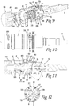
Fig 5 , with the tool holder in an unclamped state, - Fig. 11
- is a longitudinal section through the tool holder and the parts of the clamping device shown in
Fig 5 , with the tool holder in an unclamped state, and - Fig. 12
- is a cross-section according to the line XII-XII in
Fig 10 . - A
clamping device 1 according to an embodiment of the present invention is illustrated inFigs 1 and 2 in a longitudinal section through the longitudinal axis thereof. Theclamping device 1 is configured to releasably clamp a tool holder 80 (very schematically illustrated in the drawings) to arotatable spindle 2 in the clamping device and enable the machining of a work piece by means of a cutting tool (not shown) fixed to thetool holder 80. - The
spindle 2 is rotatably mounted to ahousing 3 of theclamping device 1 by means of rollingbearings 4, for instance in the form of tapered roller bearings or any other suitable type of roller bearings. Thespindle 2 has afront end 2a, arear end 2b and abore 5 which intersects thefront end 2a and extends rearwardly therefrom. Thus, thebore 5 has anentrance opening 5a (seeFig 9 ) at thefront end 2a of the spindle. Thespindle 2 is connectable to a drive mechanism of a machine tool, for instance a drive mechanism in a tool turret of a machine tool, via aconnection pin 6 at therear end 2b of the spindle in order to allow the spindle to be driven in rotation by the drive mechanism. - A mounting portion 7 (see
Fig 9 ) for receiving a mountingshank 81 on thetool holder 80 is provided at a front end of thebore 5. This mountingshank 81 is here referred to as tool holder shank. - A
drawbar 8 is slidably mounted inside thebore 5 so as to be reciprocally moveable in thebore 5 along a longitudinal axis L thereof between an advanced releasing position (seeFigs 2 and11 ) and a retracted locking position (seeFigs 1 and7 ). Thedrawbar 8 has a front end facing the entrance opening 5a of thebore 5 and an opposite rear end. Ahead portion 9 and aneck portion 10 are provided at the front end of thedrawbar 8. Thehead portion 9 is located in front of theneck portion 10 as seen in the longitudinal direction of the drawbar, wherein thehead portion 9 is connected to theneck portion 10 via a rearwardly facing bevelledsurface 11 on thehead portion 9. A sealingring 12 is arranged between thedrawbar 8 and an inner surface of thebore 5. In the illustrated example, this sealingring 12 is received in a groove on the outer side of thedrawbar 8. - The
tool holder shank 81 is insertable into the mounting portion of thebore 5 via theentrance opening 5a at thefront end 2a of thespindle 2. Thehead portion 9 of the drawbar is received in an engagement bore 82 in thetool holder shank 81 and atubular wall 83 of the tool holder shank is received in a space between thehead portion 9 and an inner surface of thebore 5. In the illustrated embodiment, the mountingportion 7 of thebore 5 is conically shaped and has a somewhat "triangular" or polygonal, non-circular cross-sectional shape adapted to receive a similarly shapedtool holder shank 81. The conical shape ensures a connection free from play in the radial as well as the axial direction between thetool holder shank 81 and thespindle 2, whereas the non-circular cross-section ensures a non-rotatable fixation of thetool holder shank 81 to thespindle 2. However, the mounting portion of thebore 5 could also have any other suitable shape for receiving other types of tool holder shanks. -
Engagement members 20 in the form of segments are arranged around thedrawbar 8 at a front end thereof. Under the effect of a movement of thedrawbar 8 from the advanced releasing position to the retracted locking position, theengagement members 20 are moveable from a first position (seeFigs 2 and11 ), in which theengagement members 20 allow thetool holder shank 81 to move into and out of the mounting portion of thebore 5, to a second position (seeFigs 1 and7 ), in which theengagement members 20 are in locking engagement with anengagement groove 84 in the engagement bore 82 in thetool holder shank 81 and thereby keep thetool holder shank 81 secured to thespindle 2. - In the illustrated embodiment, the
engagement members 20 are arranged around theneck portion 10 of thedrawbar 8 and held in place around the neck portion by means of a retainer ring 21 (seeFig 7 ) and an elastic O-ring 22, which are arranged in thebore 5 and surround theneck portion 10. Eachengagement member 20 has an outwardly facingflange portion 23 engaged in an inner groove in theretainer ring 21. The O-ring 22 is received in an outwardly facing groove at the rear end of eachengagement member 20. Acompression spring 24, athrust ring 25 and astop ring 26 are also arranged in thebore 5 and configured to surround thedrawbar 8. Thecompression spring 24 is mounted between a shoulder on thedrawbar 8 and thethrust ring 25 and it is configured to urge thethrust ring 25, theretainer ring 21 and theengagement members 20 forwards. The forward movement of theretainer ring 21 towards the entrance opening of thebore 5 is limited by thestop ring 26, which is mounted in a groove in an inner surface of thebore 5. - At its front end, each
engagement member 20 is provided with an outwardly directedengagement flange 27, which is configured to be in engagement with theengagement groove 84 in thetool holder shank 81 when theengagement member 20 is in the above-mentioned second position. When thedrawbar 8 is in the advanced releasing position, the front ends of theengagement members 20 are located behind thehead portion 9 of thedrawbar 8 and theengagement flanges 27 are out of engagement with theengagement groove 84 in thetool holder shank 81, as illustrated inFigs 2 and11 . When thedrawbar 8 is moved axially rearwards in thebore 5 along the longitudinal axis L thereof, thebevelled surface 11 on thehead portion 9 of the drawbar will come into contact with the front ends of theengagement members 20, wherein the front ends of theengagement members 20 will slide on thisbevelled surface 11 and be pressed outwards so that theengagement flanges 27 on the engagement members come into engagement with theengagement groove 84 in thetool holder shank 81, whereupon thetool holder shank 81 will be pulled by thedrawbar 8 into firm contact with inner surfaces of thespindle 2 within the mounting portion of thebore 5. - The
clamping device 1 further comprises anactuating sleeve 13, which is concentric with thespindle 2 and arranged around aperipheral wall 14 of thespindle 2. Theactuating sleeve 13 is slidably mounted to thisperipheral wall 14 so as to be axially moveable in relation to thespindle 2 along the longitudinal axis L. Theactuating sleeve 13 is non-rotatably mounted to thespindle 2, i.e. prevented from rotating in relation to thespindle 2, and consequently configured to rotate together with thespindle 2. Amotion transferring mechanism 30 is mounted to thespindle 2 and configured to transfer an axial movement of theactuating sleeve 13 in a first axial direction D in relation to thespindle 2 into a movement of thedrawbar 8 from the advanced releasing position to the retracted locking position. In the illustrated embodiment, this first axial direction D is a direction towards therear end 2b of thespindle 2. Thus, in this case a movement of thedrawbar 8 from the advanced releasing position to the retracted locking position is effected by an axial movement of theactuating sleeve 13 rearwards along thespindle 2. However, as an alternative, theactuating sleeve 13 and themotion transferring mechanism 30 could be arranged to co-operate in such a manner that a movement of thedrawbar 8 from the advanced releasing position to the retracted locking position is effected by an axial movement of theactuating sleeve 13 forwards along thespindle 2. - Furthermore, the
clamping device 1 comprises ahydraulic cylinder arrangement 50 for moving theactuating sleeve 13 axially in relation to thespindle 2. Thishydraulic cylinder arrangement 50 comprises acylinder casing 51, which is concentric with theactuating sleeve 13 and which is fixed tospindle 2 on the outside thereof so as to be rotatable in relation to thehousing 3 together with thespindle 2. In the illustrated embodiment, thecylinder casing 51 is fixed to thespindle 2 through a threaded joint formed by aninternal thread 52 on thecylinder casing 51 and a correspondingexternal thread 53 on thespindle 2. However, thecylinder casing 51 may of course be fixed to thespindle 2 in any other suitable manner. - The
hydraulic cylinder arrangement 50 also comprises anannular piston head 54, which is fixed to or fixedly connected to theactuating sleeve 13. In the illustrated embodiment, thepiston head 54 forms part of anannular piston member 55, which is concentric with theactuating sleeve 13 and configured to surround a part of it. Thispiston member 55 comprises a sleeve-shapedbase part 56, which is secured to theactuating sleeve 13 on the outside thereof. Thebase part 56 is fixed to theactuating sleeve 13 by means of alock ring 57, which is received in an annular groove on the outer side of the actuating sleeve and which prevents theactuating sleeve 13 and thepiston member 55 from moving axially in relation to each other. In this case, thepiston head 54 is formed as an annular external protuberance on thepiston member 55. In the illustrated embodiment, thebase part 56 of thepiston member 55 covers radial throughholes 58 in theactuating sleeve 13, wherein these throughholes 58 give access to thespindle 2 and thedrawbar 8 for insertion of different components of themotion transferring mechanism 30 during the assembling of theclamping device 1. Sealing rings 59a, 59b are arranged between the actuatingsleeve 13 and thebase part 56 of the piston member on opposite sides of the through holes 58. - The
piston head 54 and theactuating sleeve 13 may as an alternative be formed in one piece, for instance with the piston head formed as an annular external protuberance on the actuating sleeve. - The
piston head 54 is slidably received in an annular space 60 inside thecylinder casing 51 and configured to divide this space into an annular firsthydraulic chamber 61a on a first side of thepiston head 54 and an annular secondhydraulic chamber 61b on an opposite second side of the piston head. Theactuating sleeve 13 is moveable together with thepiston head 54 in the above-mentioned first axial direction D by feeding of hydraulic fluid into the firsthydraulic chamber 61a in order to effect a movement of thedrawbar 8 from the advanced releasing position to the retracted locking position, and theactuating sleeve 13 is moveable together with thepiston head 54 in an opposite second axial direction by feeding of hydraulic fluid into the secondhydraulic chamber 61b. A sealingring 62 is mounted in an annular groove in an outwardly facing surface on thepiston head 54 so as to be in sealing contact with awall 63 of thecylinder casing 51 that delimits the above-mentioned space 60 in radial direction outwards. - The
actuating sleeve 13 is preferably configured to assume a self-locking axial position on thespindle 2 when thedrawbar 8 has been forced into the retracted locking position under the effect of theactuating sleeve 13 and themotion transferring mechanism 30, so as to thereby allow theactuating sleeve 13 to keep thedrawbar 8 in the retracted locking position. Hereby, thepiston head 54 only needs to be subjected to hydraulic pressure in connection with a tool changing operation when thespindle 2 is stationary and thedrawbar 8 is to be moved from the retracted locking position to the advanced releasing position and then back to the retracted locking position. In the self-locking axial position, frictional forces between the actuatingsleeve 13 and parts of themotion transferring mechanism 30 and/or thespindle 2 that are in contact with theactuating sleeve 13 prevent the actuating sleeve from being axially displaced in a direction opposite to the first axial direction D. - The
spindle 2 and thecylinder casing 51 form part of arotatable unit 64 that is rotatably received in aninner space 18 of thehousing 3. Thisrotatable unit 64 also comprises the other components that are mounted to and configured to rotate together with thespindle 2, such as theactuating sleeve 13, thedrawbar 8, thepiston member 55 and themotion transferring mechanism 30. The firsthydraulic chamber 61a is hydraulically connected to a firsthydraulic channel 65a in thehousing 3 via an annular first hydraulic connectingarea 66a at the interface between thehousing 3 and saidrotatable unit 64, and the secondhydraulic chamber 61b is hydraulically connected to a secondhydraulic channel 65b in thehousing 3 via an annular second hydraulic connectingarea 66b at said interface.Rotary seals area 66a and on either side of the second hydraulic connectingarea 66b. In the illustrated example, said rotary seals are three in number, wherein one 67b of them is arranged between the first and second hydraulic connectingareas - In the illustrated embodiment, the above-mentioned
rotatable unit 64 also comprises a sleeve-shaped connectingpiece 68, which is clamped between a front end of thecylinder casing 51 and aninner part 4a of a rollingbearing 4 provided between thespindle 2 and thehousing 3 at thefront end 2a of the spindle. In this case, the firsthydraulic chamber 61a is connected to the first hydraulic connectingareas 66a throughchannels 69 provided in the connectingpiece 68. There is a small play between the outer surfaces of thecylinder casing 51 and the connectingpiece 68 and the opposed inner surfaces of thehousing 3. - A cylindrical outer surface of the
actuating sleeve 13 at a front end thereof, i.e. at the end of the actuating sleeve that faces towards thefront end 2a of thespindle 2, is in sliding contact with a cylindrical inner surface of the connectingpiece 68. A sealingring 70 is mounted in an annular groove in said cylindrical outer surface on the actuating sleeve so as to be in sealing contact with the opposed inner surface of the connectingpiece 68. Another sealingring 71 is mounted in an annular groove in a cylindrical inner surface of theactuating sleeve 13 at a rear end thereof, i.e. at the end of the actuating sleeve that faces towards therear end 2b of thespindle 2, wherein this sealingring 71 is in sealing contact with the opposedperipheral wall 14 of thespindle 2. - Each
rotary seal annular groove 72 provided in an inner surface of thehousing 3 at the above-mentioned interface. However, eachrotary seal rotatable unit 64. In the illustrated embodiment, eachrotary seal inner seal ring 73 and an outer elastomeric O-ring 74, which surrounds theseal ring 73 and which is in a radially compressed state and configured to press theseal ring 73 against an outer surface of saidrotatable unit 64. - In the illustrated embodiments, a
release spring 17, preferably in the form of a helical compression spring, is mounted in a space inside thespindle 2 and configured to act on the rear end of thedrawbar 8 in order to urge the drawbar towards the advanced releasing position. Thedrawbar 8 is moveable, under the effect of theactuating sleeve 13 and themotion transferring mechanism 30, from the advanced releasing position to the retracted locking position against the action of a spring force from thisrelease spring 17. Therelease spring 17 is with advantage arranged along the longitudinal axis L, behind thedrawbar 8. - The
motion transferring mechanism 30 may be designed in many different manners. In the illustrated embodiment, the motion transferring mechanism comprises threewedges 31, which are spaced apart in the circumferential direction of thespindle 2. Eachwedge 31 is received in arespective aperture 32 that extends radially through the above-mentionedperipheral wall 14 of thespindle 2, wherein thewedges 31 are configured to press thedrawbar 8 towards the retracted locking position when they are pressed radially inwards in the associatedapertures 32. Eachwedge 31 comprises a first pressure receiving surface 33 (seeFigs 7 and9 ) which faces outwards from thespindle 2, and theactuating sleeve 13 is on its inner side provided with a firstpressure applying surface 34 which faces inwards for contacting the firstpressure receiving surface 33 on each wedge. The firstpressure applying surface 34 has a radial distance to the longitudinal axis L that increases as seen in the above-mentioned first axial direction D. The firstpressure applying surface 34 is configured to press thewedges 31 radially inwards in theapertures 32 by pressing against the firstpressure receiving surface 33 on each wedge when theactuating sleeve 13 is moved in the first axial direction D. - The illustrated
motion transferring mechanism 30 also comprises threewedge engagement members 35, which project radially from thedrawbar 8 into a respective one of theapertures 32 and which are fixed to the drawbar so as to be moveable along the longitudinal axis L together with the drawbar. Thus, a movement of awedge engagement member 35 along the longitudinal axis L will cause a corresponding movement of thedrawbar 8. Eachwedge engagement member 35 is in contact with one of thewedges 31. In order to facilitate the assembly of theclamping device 1, the illustratedwedge engagement members 35 are formed as separate elements mounted in a respective radial recess in thedrawbar 8. However, thewedge engagement members 35 may as an alternative be mounted to thedrawbar 8 in any other suitable manner or formed in one piece with the drawbar. - The
motion transferring mechanism 30 may comprise any suitable number ofwedges 31 and associatedwedge engagement members 35 arranged to extend through a corresponding number ofapertures 32 in theperipheral wall 14 of thespindle 2. Theapertures 32 and the associatedwedges 31 andwedge engagement members 35 are preferably evenly distributed in the circumferential direction of theperipheral wall 14. - Each
wedge engagement member 35 has aslide surface 36 which faces towards thefront end 2a of thespindle 2, and eachaperture 32 has aslide surface 37 which faces towards therear end 2b of the spindle. Furthermore, eachwedge 31 has afirst wedge surface 38 which faces towards therear end 2b of the spindle and asecond wedge surface 39 which faces towards thefront end 2a of the spindle, wherein these first and second wedge surfaces 38, 39 approach each other in a radial direction towards the longitudinal axis L. Thefirst wedge surface 38 of eachwedge 31 is in contact with theslide surface 36 of the associatedwedge engagement member 35 and thesecond wedge surface 39 of each wedge is in contact with theslide surface 37 of the associatedaperture 32. When thewedges 31 are pressed radially inwards in theapertures 32 by theactuating sleeve 13, the first and second wedge surfaces 38, 39 of eachwedge 31 will slide and press against the corresponding slide surfaces 36, 37 of the associatedwedge engagement member 35 andaperture 32 and thereby force thedrawbar 8 to move towards the retracted locking position. - The first
pressure applying surface 34 and the firstpressure receiving surfaces 33 are preferably inclined in relation to the longitudinal axis L by such an angle α (seeFig 11 ) that thewedges 31 will keep theactuating sleeve 13 in a self-locking axial position on thespindle 2 when thedrawbar 8 has been forced into the retracted locking position under the effect of theactuating sleeve 13 and thewedges 31. - Each
wedge 31 may also comprise a secondpressure receiving surface 43 which faces outwards from thespindle 2, wherein theactuating sleeve 13 on its inner side is provided with a secondpressure applying surface 44 which faces inwards for contacting the secondpressure receiving surface 43 on each wedge. The secondpressure applying surface 44 has a radial distance to the longitudinal axis L that increases as seen in the first axial direction D. The secondpressure applying surface 44 and the secondpressure receiving surfaces 43 are inclined in relation to the longitudinal axis L by an angle β (seeFig 11 ) which is larger than the above-mentioned angle α. The first and secondpressure applying surfaces pressure receiving surfaces actuating sleeve 13 and on eachwedge 31, respectively, such that, upon a movement of theactuating sleeve 13 in the first axial direction D, the secondpressure applying surface 44 is configured to slide and press against the secondpressure receiving surface 43 on each wedge during an initial first phase of the movement, whereupon the firstpressure applying surface 34 is configured to slide and press against the firstpressure receiving surface 33 on each wedge during a subsequent second phase of the movement. - Each
wedge engagement member 35 further comprises a releasepressure receiving surface 40 which faces towards therear end 2b of thespindle 2, and theactuating sleeve 13 comprises a releasepressure applying surface 41 which faces towards thefront end 2a of the spindle. The releasepressure applying surface 41 of theactuating sleeve 13 is configured to come into contact with the releasepressure receiving surfaces 40 of thewedge engagement members 35 when theactuating sleeve 13 is moved in the above-mentioned second axial direction, to thereby allow the actuating sleeve to exert a forwardly directed axial force on thedrawbar 8 via thewedge engagement members 35 during a final phase of the movement of the drawbar from the retracted locking position to the advanced releasing position. - In the illustrated embodiment, supporting
segments 45 and pins 46 are arranged between the actuatingsleeve 13 and thespindle 2. The supportingsegments 45 are arranged on the inner side of theactuating sleeve 13 and are fixed to the actuating sleeve by means ofscrews 47, as illustrated inFig 12 . The supportingsegments 45 support thewedges 31 such that they are kept in place and are prevented from being dislocated with respect to theactuating sleeve 13 in the circumferential direction. Eachpin 46 is accommodated partly in arecess 48 in thespindle 2 and partly in alongitudinal groove 49 in theactuating sleeve 13. Thepins 46 are fixed in axial position in relation to thespindle 2 by being received in therecesses 48 on the outer side of the spindle. Thepins 46 are slidably received in thelongitudinal grooves 49 on the inner side of theactuating sleeve 13, and theactuating sleeve 13 is thereby allowed to move axially in relation to thepins 46 when the actuating sleeve is axially moved in relation to thespindle 2. When theactuating sleeve 13 is in the advanced releasing position, a rear end of eachpin 46 is partly received in arecess 42 in a supportingsegment 45, as illustrated inFig 11 . Thepins 46 prevent mutual rotation between the actuatingsleeve 13 and thespindle 2. Consequently, when thespindle 2 is rotated, theactuating sleeve 13 will rotate together with thespindle 2 with the same rotational speed and cannot be displaced in relation to thespindle 2 in the circumferential direction. - When a
tool holder 80 is to be clamped to thespindle 2, thetool holder shank 81 is inserted into the mountingportion 7 of thebore 5 with thespindle 2 kept in a stationary position and thedrawbar 8 positioned in the advanced releasing position, as illustrated inFigs 2 and11 . Hereby, thehead portion 9 of the drawbar is received in the engagement bore 82 in thetool holder shank 81 and theengagement groove 84 in thetool holder shank 81 is positioned on the outside of theengagement flanges 27 of theengagement members 20. Thereupon, hydraulic oil is fed into the firsthydraulic chamber 61a in order to move theactuating sleeve 13 in the first axial direction D. During a first phase of this axial movement of theactuating sleeve 13, the secondpressure applying surface 44 on theactuating sleeve 13 will slide and press against the secondpressure receiving surfaces 43 on thewedges 31. Hereby, thewedges 31 will be pressed radially inwards and thedrawbar 8 will be axially displaced towards the retracted locking position. Due to the relatively steep inclination β of the second pressure applying and receivingsurfaces wedges 31 will initially move inwards rather fast, which results in a relatively quick displacement of thedrawbar 8. The relatively steep angle β is advantageous since the initial displacement of thedrawbar 8 does not require much force. The first and secondpressure applying surfaces pressure receiving surfaces actuating sleeve 13 has been moved such a distance that the secondpressure applying surface 44 has passed the secondpressure receiving surface 43 and the firstpressure applying surface 34 reaches the firstpressure receiving surface 33, i.e. at the transition between these respective surfaces, thedrawbar 8 has almost reached its final destination at the rear end of thebore 5. Hence, for the final clamping phase, in which a large force is beneficial, the first pressure applying and receivingsurfaces actuating sleeve 13 will result in a very small radial displacement of thewedges 31, and an even smaller axial displacement of thedrawbar 8, which consequently will provide a force amplifying effect that will make it possible for thedrawbar 8 to pull thetool holder shank 81 with a large force into firm engagement with thespindle 2. Furthermore, the small inclination α of the first pressure applying and receivingsurfaces piston head 54 may be released when thedrawbar 8 has reached the retracted locking position. - When a tool changing operation is to be performed and the
tool holder 80 is to be released from thespindle 2, the rotation of thespindle 2 is stopped and hydraulic oil is fed into the secondhydraulic chamber 61b in order to move theactuating sleeve 13 in the second axial direction, opposite to the first axial direction D. When theactuating sleeve 13 is subjected to a sufficient force in said second axial direction by the hydraulic pressure in the secondhydraulic chamber 61b, the self-locking frictional engagement between the firstpressure applying surface 34 on theactuating sleeve 13 and the firstpressure receiving surfaces 33 on thewedges 31 will be released, whereupon theactuating sleeve 13 is moveable in relation to thespindle 2 in the second axial direction under the effect of the hydraulic pressure in the secondhydraulic chamber 61b. When theactuating sleeve 13 is moved in this direction, the spring force exerted by therelease spring 17 on the rear end of thedrawbar 8 will push the drawbar axially towards the advanced releasing position. Hereby, thewedge engagement members 35 will exert a force on thewedges 31 and press them radially outwards. When theactuating sleeve 13 has been moved a certain distance in the second axial direction, the releasepressure applying surface 41 on theactuating sleeve 13 will come into contact with the releasepressure receiving surfaces 40 on thewedge engagement members 35, which will allow theactuating sleeve 13 to exert an axial force on thedrawbar 8 via thewedge engagement members 35 that will push the outer end of thehead portion 9 of thedrawbar 8 against asurface 85 in the engagement bore 82 in thetool holder shank 81 and thereby release thetool holder shank 81 from thespindle 2. - The invention is of course not in any way restricted to the embodiments described above. On the contrary, many possibilities to modifications thereof will be apparent to a person with ordinary skill in the art without departing from the basic idea of the invention such as defined in the appended claims.
Claims (12)
- A clamping device for releasably holding a tool holder shank, the clamping device (1) comprising:- a housing (3);- a spindle (2) rotatably mounted inside the housing (3) and having a front end, a rear end and a bore (5) which intersects the front end and extends rearwardly therefrom, wherein a mounting portion (7) for receiving the tool holder shank (81) is provided at a front end of the bore (5);- a drawbar (8) slidably mounted inside the bore (5) so as to be reciprocally moveable in the bore along a longitudinal axis (L) thereof between an advanced releasing position and a retracted locking position;- engagement members (20) arranged around the drawbar (8) at a front end thereof, wherein the engagement members (20), under the effect of a movement of the drawbar (8) from the advanced releasing position to the retracted locking position, are moveable from a first position, in which the engagement members (20) allow the tool holder shank (81) to move into and out of said mounting portion of the bore (5), to a second position, in which the engagement members (20) are in locking engagement with the tool holder shank (81) and keep it secured to the spindle (2),characterized in that the clamping device (1) further comprises:- a hydraulically operated actuating sleeve (13) arranged inside the housing (3), wherein the actuating sleeve (13) is arranged around a peripheral wall (14) of the spindle (2) and slidably mounted to this peripheral wall (14) so as to be axially moveable in relation to the spindle (2);- a motion transferring mechanism (30) arranged inside the housing (3), wherein the motion transferring mechanism (30) is mounted to the spindle (2) and configured to transfer an axial movement of the actuating sleeve (13) in a first axial direction (D) in relation to the spindle (2) into a movement of the drawbar (8) from the advanced releasing position to the retracted locking position; and- a hydraulic cylinder arrangement (50) arranged inside the housing (3) and configured to move the actuating sleeve (13) axially in relation to the spindle (2), wherein the hydraulic cylinder arrangement (50) comprises a cylinder casing (51), which is concentric with the actuating sleeve (13) and which is fixed to spindle (2) on the outside thereof so as to be rotatable in relation to the housing (3) together with the spindle (2), and an annular piston head (54), which is fixed to or fixedly connected to the actuating sleeve (13), the piston head (54) being slidably received in an annular space (60) inside the cylinder casing (51) and configured to divide this space into an annular first hydraulic chamber (61a) on a first side of the piston head and an annular second hydraulic chamber (61b) on an opposite second side of the piston head, wherein the actuating sleeve (13) is moveable together with the piston head (54) in said first axial direction (D) by feeding of hydraulic fluid into the first hydraulic chamber (61a) and in an opposite second axial direction by feeding of hydraulic fluid into the second hydraulic chamber (61b).
- A clamping device according to claim 1, characterized in:- that the spindle (2) and the cylinder casing (51) form part of a rotatable unit (64) that is rotatably received in an inner space (18) of the housing (3);- that the first hydraulic chamber (61a) is hydraulically connected to a first hydraulic channel (65a) in the housing (3) via an annular first hydraulic connecting area (66a) at the interface between the housing (3) and said rotatable unit (64);- that the second hydraulic chamber (61b) is hydraulically connected to a second hydraulic channel (65b) in the housing (3) via an annular second hydraulic connecting area (66b) at said interface; and- that rotary seals (67a, 67b, 67c) are arranged at said interface on either side of the first hydraulic connecting area (66a) and on either side of the second hydraulic connecting area (66b).
- A clamping device according to claim 2, characterized in that each rotary seal (67a, 67b, 67c) is arranged in a respective annular groove (72) arranged in the housing (3) at said interface.
- A clamping device according to claim 2 or 3, characterized in that each rotary seal (67a, 67b, 67c) comprises an inner seal ring (73) and an outer elastomeric O-ring (74), which surrounds the seal ring (73) and which is in a radially compressed state and configured to press the seal ring (73) against an outer surface of said rotatable unit (64).
- A clamping device according to any of claims 1-4, characterized in that the actuating sleeve (13) is configured to assume a self-locking axial position on the spindle (2) when the drawbar (8) has been forced into the retracted locking position under the effect of the actuating sleeve (13) and the motion transferring mechanism (30), so as to thereby keep the drawbar (8) in the retracted locking position.
- A clamping device according to any of claims 1-5, characterized in that the piston head (54) forms part of an annular piston member (55), which is secured to the actuating sleeve (13).
- A clamping device according to any of claims 1-5, characterized in that the piston head (54) and the actuating sleeve (13) are formed in one piece.
- A clamping device according to any of claims 1-7, characterized in that the cylinder casing (51) is fixed to the spindle (2) through a threaded joint formed by an internal thread (52) on the cylinder casing (51) and a corresponding external thread (53) on the spindle (2).
- A clamping device according to any of claims 1-8, characterized in:- that the motion transferring mechanism (30) comprises two or more wedges (31) spaced apart in the circumferential direction of the spindle (2), each wedge (31) being received in a respective aperture (32) that extends radially through said peripheral wall (14) of the spindle (2), wherein the wedges (31) are configured to press the drawbar (8) towards the retracted locking position when they are pressed radially inwards in the associated apertures (32);- that each wedge (31) comprises a first pressure receiving surface (33) which faces outwards from the spindle (2);- that the actuating sleeve (13) on its inner side is provided with a first pressure applying surface (34) which faces inwards for contacting the first pressure receiving surface (33) on each wedge, the first pressure applying surface (34) having a radial distance to the longitudinal axis (L) that increases as seen in said first axial direction (D); and- that the first pressure applying surface (34) is configured to press each wedge (31) radially inwards in the associated aperture (32) by pressing against the first pressure receiving surface (33) on each wedge when the actuating sleeve (13) is moved in said first axial direction (D).
- A clamping device according to claim 9, characterized in that the first pressure applying surface (34) and the first pressure receiving surfaces (33) are inclined in relation to the longitudinal axis (L) by such an angle α that the wedges (31) will keep the actuating sleeve (13) in a self-locking axial position on the spindle (2) when the drawbar (8) has been forced into the retracted locking position under the effect of the actuating sleeve (13) and the wedges (31).
- A clamping device according to claim 10, characterized in:- that each wedge (31) comprises a second pressure receiving surface (43) which faces outwards from the spindle (2);- that the actuating sleeve (13) on its inner side is provided with a second pressure applying surface (44) which faces inwards for contacting the second pressure receiving surface (43) on each wedge (31), the second pressure applying surface (44) having a radial distance to the longitudinal axis (L) that increases as seen in said first axial direction (D);- that the second pressure applying surface (44) and the second pressure receiving surfaces (43) are inclined in relation to the longitudinal axis (L) by an angle β which is larger than the angle α; and- that the first and second pressure applying surfaces (34, 44) and the first and second pressure receiving surfaces (33, 43) are arranged consecutively on the actuating sleeve (13) and on each wedge (31), respectively, such that, upon a movement of the actuating sleeve (13) in the first axial direction (D), the second pressure applying surface (44) is configured to slide and press against the second pressure receiving surface (43) on each wedge during a first phase of the movement and the first pressure applying surface (34) is configured to slide and press against the first pressure receiving surface (33) on each wedge during a subsequent second phase of the movement.
- A clamping device according to any of claims 1-11, characterized in that the drawbar (8), under the effect of the actuating sleeve (13) and the motion transferring mechanism (30), is moveable from the advanced releasing position to the retracted locking position against the action of a spring force from a release spring (17) arranged inside the spindle (2).
Priority Applications (5)
| Application Number | Priority Date | Filing Date | Title |
|---|---|---|---|
| EP19210457.8A EP3825046B1 (en) | 2019-11-20 | 2019-11-20 | Clamping device for tool holder |
| US17/778,330 US12280437B2 (en) | 2019-11-20 | 2020-11-16 | Clamping device for tool holder |
| JP2022529034A JP7679372B2 (en) | 2019-11-20 | 2020-11-16 | Clamping device for tool holders |
| PCT/EP2020/082169 WO2021099228A1 (en) | 2019-11-20 | 2020-11-16 | Clamping device for tool holder |
| KR1020227019805A KR102911496B1 (en) | 2019-11-20 | 2020-11-16 | Clamping device for tool holder |
Applications Claiming Priority (1)
| Application Number | Priority Date | Filing Date | Title |
|---|---|---|---|
| EP19210457.8A EP3825046B1 (en) | 2019-11-20 | 2019-11-20 | Clamping device for tool holder |
Publications (2)
| Publication Number | Publication Date |
|---|---|
| EP3825046A1 true EP3825046A1 (en) | 2021-05-26 |
| EP3825046B1 EP3825046B1 (en) | 2022-08-03 |
Family
ID=68621194
Family Applications (1)
| Application Number | Title | Priority Date | Filing Date |
|---|---|---|---|
| EP19210457.8A Active EP3825046B1 (en) | 2019-11-20 | 2019-11-20 | Clamping device for tool holder |
Country Status (5)
| Country | Link |
|---|---|
| US (1) | US12280437B2 (en) |
| EP (1) | EP3825046B1 (en) |
| JP (1) | JP7679372B2 (en) |
| KR (1) | KR102911496B1 (en) |
| WO (1) | WO2021099228A1 (en) |
Cited By (3)
| Publication number | Priority date | Publication date | Assignee | Title |
|---|---|---|---|---|
| EP4108368A1 (en) * | 2021-06-23 | 2022-12-28 | AB Sandvik Coromant | Clamping device for tool holder |
| EP4108367A1 (en) * | 2021-06-23 | 2022-12-28 | AB Sandvik Coromant | Clamping device for tool holder |
| WO2023062240A1 (en) * | 2021-10-15 | 2023-04-20 | Wto Vermögensverwaltung Gmbh | Clamping system with polygonal receptacle for a hollow shaft |
Citations (5)
| Publication number | Priority date | Publication date | Assignee | Title |
|---|---|---|---|---|
| JPS5942234A (en) * | 1982-08-30 | 1984-03-08 | Yamazaki Mazak Corp | Tool head |
| US4915553A (en) * | 1989-02-01 | 1990-04-10 | Tree Machine Tool, Co. | Tool retention and ejection mechanism |
| DE4028775C1 (en) * | 1990-03-28 | 1991-07-25 | Ott Maschinentechnik Gmbh, 8960 Kempten, De | |
| US5707186A (en) * | 1995-11-23 | 1998-01-13 | Gat Gesellschaft Fur Antriebstechnik Mbh | Chuck with an integrated rotary union for fluid flow |
| EP1468767B1 (en) | 2003-04-15 | 2016-12-07 | Sandvik Intellectual Property AB | Force-amplifier |
Family Cites Families (7)
| Publication number | Priority date | Publication date | Assignee | Title |
|---|---|---|---|---|
| DE4341167A1 (en) * | 1993-12-02 | 1995-06-08 | Karl Hiestand | Device for transferring a print medium |
| US6036415A (en) * | 1998-09-04 | 2000-03-14 | Hardinge, Inc. | Spindle for gripping and closing a mounting member |
| SE514356C2 (en) * | 1999-06-09 | 2001-02-12 | Sandvik Ab | Holder for detachable mounting of cutting tools |
| SE525190C2 (en) * | 2003-04-15 | 2004-12-21 | Sandvik Ab | Gas spring with drawbar in two pieces |
| JP2006062042A (en) * | 2004-08-27 | 2006-03-09 | Nippei Toyama Corp | Spindle device |
| JP2006123098A (en) * | 2004-10-29 | 2006-05-18 | Hiihaisuto Seiko Kk | Machine tool chuck device |
| JP2010179399A (en) * | 2009-02-05 | 2010-08-19 | Mitsubishi Heavy Ind Ltd | Main-shaft device for machine tool |
-
2019
- 2019-11-20 EP EP19210457.8A patent/EP3825046B1/en active Active
-
2020
- 2020-11-16 US US17/778,330 patent/US12280437B2/en active Active
- 2020-11-16 JP JP2022529034A patent/JP7679372B2/en active Active
- 2020-11-16 KR KR1020227019805A patent/KR102911496B1/en active Active
- 2020-11-16 WO PCT/EP2020/082169 patent/WO2021099228A1/en not_active Ceased
Patent Citations (5)
| Publication number | Priority date | Publication date | Assignee | Title |
|---|---|---|---|---|
| JPS5942234A (en) * | 1982-08-30 | 1984-03-08 | Yamazaki Mazak Corp | Tool head |
| US4915553A (en) * | 1989-02-01 | 1990-04-10 | Tree Machine Tool, Co. | Tool retention and ejection mechanism |
| DE4028775C1 (en) * | 1990-03-28 | 1991-07-25 | Ott Maschinentechnik Gmbh, 8960 Kempten, De | |
| US5707186A (en) * | 1995-11-23 | 1998-01-13 | Gat Gesellschaft Fur Antriebstechnik Mbh | Chuck with an integrated rotary union for fluid flow |
| EP1468767B1 (en) | 2003-04-15 | 2016-12-07 | Sandvik Intellectual Property AB | Force-amplifier |
Cited By (7)
| Publication number | Priority date | Publication date | Assignee | Title |
|---|---|---|---|---|
| EP4108368A1 (en) * | 2021-06-23 | 2022-12-28 | AB Sandvik Coromant | Clamping device for tool holder |
| EP4108367A1 (en) * | 2021-06-23 | 2022-12-28 | AB Sandvik Coromant | Clamping device for tool holder |
| WO2022268373A1 (en) * | 2021-06-23 | 2022-12-29 | Ab Sandvik Coromant | Clamping device for tool holder |
| WO2022268372A1 (en) * | 2021-06-23 | 2022-12-29 | Ab Sandvik Coromant | Clamping device for tool holder |
| CN117279727A (en) * | 2021-06-23 | 2023-12-22 | 山特维克科洛曼特公司 | Clamping device for tool holder |
| JP2024525391A (en) * | 2021-06-23 | 2024-07-12 | エービー サンドビック コロマント | Clamping device for a tool holder |
| WO2023062240A1 (en) * | 2021-10-15 | 2023-04-20 | Wto Vermögensverwaltung Gmbh | Clamping system with polygonal receptacle for a hollow shaft |
Also Published As
| Publication number | Publication date |
|---|---|
| WO2021099228A1 (en) | 2021-05-27 |
| JP2023503059A (en) | 2023-01-26 |
| JP7679372B2 (en) | 2025-05-19 |
| KR102911496B1 (en) | 2026-01-12 |
| US20230001493A1 (en) | 2023-01-05 |
| KR20220100021A (en) | 2022-07-14 |
| EP3825046B1 (en) | 2022-08-03 |
| US12280437B2 (en) | 2025-04-22 |
Similar Documents
| Publication | Publication Date | Title |
|---|---|---|
| US12280437B2 (en) | Clamping device for tool holder | |
| EP3825047A1 (en) | Clamping device for tool holder | |
| US20240278334A1 (en) | Clamping device for tool holder | |
| US12194545B2 (en) | Clamping device for tool holder | |
| JP7583748B2 (en) | Clamping device for tool holders | |
| US12325077B2 (en) | Clamping device for tool holder | |
| EP3922383B1 (en) | Clamping device for tool holder | |
| US12280436B2 (en) | Clamping device for tool holder | |
| EP4108367A1 (en) | Clamping device for tool holder |
Legal Events
| Date | Code | Title | Description |
|---|---|---|---|
| PUAI | Public reference made under article 153(3) epc to a published international application that has entered the european phase |
Free format text: ORIGINAL CODE: 0009012 |
|
| STAA | Information on the status of an ep patent application or granted ep patent |
Free format text: STATUS: THE APPLICATION HAS BEEN PUBLISHED |
|
| AK | Designated contracting states |
Kind code of ref document: A1 Designated state(s): AL AT BE BG CH CY CZ DE DK EE ES FI FR GB GR HR HU IE IS IT LI LT LU LV MC MK MT NL NO PL PT RO RS SE SI SK SM TR |
|
| STAA | Information on the status of an ep patent application or granted ep patent |
Free format text: STATUS: REQUEST FOR EXAMINATION WAS MADE |
|
| 17P | Request for examination filed |
Effective date: 20211126 |
|
| RBV | Designated contracting states (corrected) |
Designated state(s): AL AT BE BG CH CY CZ DE DK EE ES FI FR GB GR HR HU IE IS IT LI LT LU LV MC MK MT NL NO PL PT RO RS SE SI SK SM TR |
|
| GRAP | Despatch of communication of intention to grant a patent |
Free format text: ORIGINAL CODE: EPIDOSNIGR1 |
|
| STAA | Information on the status of an ep patent application or granted ep patent |
Free format text: STATUS: GRANT OF PATENT IS INTENDED |
|
| INTG | Intention to grant announced |
Effective date: 20220419 |
|
| RIN1 | Information on inventor provided before grant (corrected) |
Inventor name: MAETLIK, GUNNAR |
|
| GRAS | Grant fee paid |
Free format text: ORIGINAL CODE: EPIDOSNIGR3 |
|
| GRAA | (expected) grant |
Free format text: ORIGINAL CODE: 0009210 |
|
| STAA | Information on the status of an ep patent application or granted ep patent |
Free format text: STATUS: THE PATENT HAS BEEN GRANTED |
|
| AK | Designated contracting states |
Kind code of ref document: B1 Designated state(s): AL AT BE BG CH CY CZ DE DK EE ES FI FR GB GR HR HU IE IS IT LI LT LU LV MC MK MT NL NO PL PT RO RS SE SI SK SM TR |
|
| REG | Reference to a national code |
Ref country code: AT Ref legal event code: REF Ref document number: 1508339 Country of ref document: AT Kind code of ref document: T Effective date: 20220815 Ref country code: CH Ref legal event code: EP |
|
| REG | Reference to a national code |
Ref country code: DE Ref legal event code: R096 Ref document number: 602019017724 Country of ref document: DE |
|
| REG | Reference to a national code |
Ref country code: IE Ref legal event code: FG4D |
|
| REG | Reference to a national code |
Ref country code: LT Ref legal event code: MG9D |
|
| REG | Reference to a national code |
Ref country code: NL Ref legal event code: MP Effective date: 20220803 |
|
| PG25 | Lapsed in a contracting state [announced via postgrant information from national office to epo] |
Ref country code: SE Free format text: LAPSE BECAUSE OF FAILURE TO SUBMIT A TRANSLATION OF THE DESCRIPTION OR TO PAY THE FEE WITHIN THE PRESCRIBED TIME-LIMIT Effective date: 20220803 Ref country code: RS Free format text: LAPSE BECAUSE OF FAILURE TO SUBMIT A TRANSLATION OF THE DESCRIPTION OR TO PAY THE FEE WITHIN THE PRESCRIBED TIME-LIMIT Effective date: 20220803 Ref country code: PT Free format text: LAPSE BECAUSE OF FAILURE TO SUBMIT A TRANSLATION OF THE DESCRIPTION OR TO PAY THE FEE WITHIN THE PRESCRIBED TIME-LIMIT Effective date: 20221205 Ref country code: NO Free format text: LAPSE BECAUSE OF FAILURE TO SUBMIT A TRANSLATION OF THE DESCRIPTION OR TO PAY THE FEE WITHIN THE PRESCRIBED TIME-LIMIT Effective date: 20221103 Ref country code: NL Free format text: LAPSE BECAUSE OF FAILURE TO SUBMIT A TRANSLATION OF THE DESCRIPTION OR TO PAY THE FEE WITHIN THE PRESCRIBED TIME-LIMIT Effective date: 20220803 Ref country code: LV Free format text: LAPSE BECAUSE OF FAILURE TO SUBMIT A TRANSLATION OF THE DESCRIPTION OR TO PAY THE FEE WITHIN THE PRESCRIBED TIME-LIMIT Effective date: 20220803 Ref country code: LT Free format text: LAPSE BECAUSE OF FAILURE TO SUBMIT A TRANSLATION OF THE DESCRIPTION OR TO PAY THE FEE WITHIN THE PRESCRIBED TIME-LIMIT Effective date: 20220803 Ref country code: FI Free format text: LAPSE BECAUSE OF FAILURE TO SUBMIT A TRANSLATION OF THE DESCRIPTION OR TO PAY THE FEE WITHIN THE PRESCRIBED TIME-LIMIT Effective date: 20220803 Ref country code: ES Free format text: LAPSE BECAUSE OF FAILURE TO SUBMIT A TRANSLATION OF THE DESCRIPTION OR TO PAY THE FEE WITHIN THE PRESCRIBED TIME-LIMIT Effective date: 20220803 |
|
| REG | Reference to a national code |
Ref country code: AT Ref legal event code: MK05 Ref document number: 1508339 Country of ref document: AT Kind code of ref document: T Effective date: 20220803 |
|
| PG25 | Lapsed in a contracting state [announced via postgrant information from national office to epo] |
Ref country code: PL Free format text: LAPSE BECAUSE OF FAILURE TO SUBMIT A TRANSLATION OF THE DESCRIPTION OR TO PAY THE FEE WITHIN THE PRESCRIBED TIME-LIMIT Effective date: 20220803 Ref country code: IS Free format text: LAPSE BECAUSE OF FAILURE TO SUBMIT A TRANSLATION OF THE DESCRIPTION OR TO PAY THE FEE WITHIN THE PRESCRIBED TIME-LIMIT Effective date: 20221203 Ref country code: HR Free format text: LAPSE BECAUSE OF FAILURE TO SUBMIT A TRANSLATION OF THE DESCRIPTION OR TO PAY THE FEE WITHIN THE PRESCRIBED TIME-LIMIT Effective date: 20220803 Ref country code: GR Free format text: LAPSE BECAUSE OF FAILURE TO SUBMIT A TRANSLATION OF THE DESCRIPTION OR TO PAY THE FEE WITHIN THE PRESCRIBED TIME-LIMIT Effective date: 20221104 |
|
| PG25 | Lapsed in a contracting state [announced via postgrant information from national office to epo] |
Ref country code: SM Free format text: LAPSE BECAUSE OF FAILURE TO SUBMIT A TRANSLATION OF THE DESCRIPTION OR TO PAY THE FEE WITHIN THE PRESCRIBED TIME-LIMIT Effective date: 20220803 Ref country code: RO Free format text: LAPSE BECAUSE OF FAILURE TO SUBMIT A TRANSLATION OF THE DESCRIPTION OR TO PAY THE FEE WITHIN THE PRESCRIBED TIME-LIMIT Effective date: 20220803 Ref country code: DK Free format text: LAPSE BECAUSE OF FAILURE TO SUBMIT A TRANSLATION OF THE DESCRIPTION OR TO PAY THE FEE WITHIN THE PRESCRIBED TIME-LIMIT Effective date: 20220803 Ref country code: CZ Free format text: LAPSE BECAUSE OF FAILURE TO SUBMIT A TRANSLATION OF THE DESCRIPTION OR TO PAY THE FEE WITHIN THE PRESCRIBED TIME-LIMIT Effective date: 20220803 Ref country code: AT Free format text: LAPSE BECAUSE OF FAILURE TO SUBMIT A TRANSLATION OF THE DESCRIPTION OR TO PAY THE FEE WITHIN THE PRESCRIBED TIME-LIMIT Effective date: 20220803 |
|
| REG | Reference to a national code |
Ref country code: DE Ref legal event code: R097 Ref document number: 602019017724 Country of ref document: DE |
|
| PG25 | Lapsed in a contracting state [announced via postgrant information from national office to epo] |
Ref country code: SK Free format text: LAPSE BECAUSE OF FAILURE TO SUBMIT A TRANSLATION OF THE DESCRIPTION OR TO PAY THE FEE WITHIN THE PRESCRIBED TIME-LIMIT Effective date: 20220803 Ref country code: EE Free format text: LAPSE BECAUSE OF FAILURE TO SUBMIT A TRANSLATION OF THE DESCRIPTION OR TO PAY THE FEE WITHIN THE PRESCRIBED TIME-LIMIT Effective date: 20220803 |
|
| PLBE | No opposition filed within time limit |
Free format text: ORIGINAL CODE: 0009261 |
|
| STAA | Information on the status of an ep patent application or granted ep patent |
Free format text: STATUS: NO OPPOSITION FILED WITHIN TIME LIMIT |
|
| PG25 | Lapsed in a contracting state [announced via postgrant information from national office to epo] |
Ref country code: MC Free format text: LAPSE BECAUSE OF FAILURE TO SUBMIT A TRANSLATION OF THE DESCRIPTION OR TO PAY THE FEE WITHIN THE PRESCRIBED TIME-LIMIT Effective date: 20220803 Ref country code: AL Free format text: LAPSE BECAUSE OF FAILURE TO SUBMIT A TRANSLATION OF THE DESCRIPTION OR TO PAY THE FEE WITHIN THE PRESCRIBED TIME-LIMIT Effective date: 20220803 |
|
| REG | Reference to a national code |
Ref country code: CH Ref legal event code: PL |
|
| 26N | No opposition filed |
Effective date: 20230504 |
|
| P01 | Opt-out of the competence of the unified patent court (upc) registered |
Effective date: 20230603 |
|
| REG | Reference to a national code |
Ref country code: BE Ref legal event code: MM Effective date: 20221130 |
|
| PG25 | Lapsed in a contracting state [announced via postgrant information from national office to epo] |
Ref country code: LI Free format text: LAPSE BECAUSE OF NON-PAYMENT OF DUE FEES Effective date: 20221130 Ref country code: CH Free format text: LAPSE BECAUSE OF NON-PAYMENT OF DUE FEES Effective date: 20221130 |
|
| PG25 | Lapsed in a contracting state [announced via postgrant information from national office to epo] |
Ref country code: SI Free format text: LAPSE BECAUSE OF FAILURE TO SUBMIT A TRANSLATION OF THE DESCRIPTION OR TO PAY THE FEE WITHIN THE PRESCRIBED TIME-LIMIT Effective date: 20220803 Ref country code: LU Free format text: LAPSE BECAUSE OF NON-PAYMENT OF DUE FEES Effective date: 20221120 |
|
| PG25 | Lapsed in a contracting state [announced via postgrant information from national office to epo] |
Ref country code: IE Free format text: LAPSE BECAUSE OF NON-PAYMENT OF DUE FEES Effective date: 20221120 |
|
| PG25 | Lapsed in a contracting state [announced via postgrant information from national office to epo] |
Ref country code: FR Free format text: LAPSE BECAUSE OF NON-PAYMENT OF DUE FEES Effective date: 20221130 Ref country code: BE Free format text: LAPSE BECAUSE OF NON-PAYMENT OF DUE FEES Effective date: 20221130 |
|
| PG25 | Lapsed in a contracting state [announced via postgrant information from national office to epo] |
Ref country code: CY Free format text: LAPSE BECAUSE OF FAILURE TO SUBMIT A TRANSLATION OF THE DESCRIPTION OR TO PAY THE FEE WITHIN THE PRESCRIBED TIME-LIMIT Effective date: 20220803 |
|
| PG25 | Lapsed in a contracting state [announced via postgrant information from national office to epo] |
Ref country code: MK Free format text: LAPSE BECAUSE OF FAILURE TO SUBMIT A TRANSLATION OF THE DESCRIPTION OR TO PAY THE FEE WITHIN THE PRESCRIBED TIME-LIMIT Effective date: 20220803 Ref country code: HU Free format text: LAPSE BECAUSE OF FAILURE TO SUBMIT A TRANSLATION OF THE DESCRIPTION OR TO PAY THE FEE WITHIN THE PRESCRIBED TIME-LIMIT; INVALID AB INITIO Effective date: 20191120 |
|
| PG25 | Lapsed in a contracting state [announced via postgrant information from national office to epo] |
Ref country code: BG Free format text: LAPSE BECAUSE OF FAILURE TO SUBMIT A TRANSLATION OF THE DESCRIPTION OR TO PAY THE FEE WITHIN THE PRESCRIBED TIME-LIMIT Effective date: 20220803 |
|
| PG25 | Lapsed in a contracting state [announced via postgrant information from national office to epo] |
Ref country code: MT Free format text: LAPSE BECAUSE OF FAILURE TO SUBMIT A TRANSLATION OF THE DESCRIPTION OR TO PAY THE FEE WITHIN THE PRESCRIBED TIME-LIMIT Effective date: 20220803 |
|
| PG25 | Lapsed in a contracting state [announced via postgrant information from national office to epo] |
Ref country code: TR Free format text: LAPSE BECAUSE OF FAILURE TO SUBMIT A TRANSLATION OF THE DESCRIPTION OR TO PAY THE FEE WITHIN THE PRESCRIBED TIME-LIMIT Effective date: 20220803 |
|
| PGFP | Annual fee paid to national office [announced via postgrant information from national office to epo] |
Ref country code: DE Payment date: 20250930 Year of fee payment: 7 |
|
| PGFP | Annual fee paid to national office [announced via postgrant information from national office to epo] |
Ref country code: GB Payment date: 20251001 Year of fee payment: 7 |
|
| PGFP | Annual fee paid to national office [announced via postgrant information from national office to epo] |
Ref country code: IT Payment date: 20251022 Year of fee payment: 7 |