EP3825045A1 - A cutting tool assembly - Google Patents
A cutting tool assembly Download PDFInfo
- Publication number
- EP3825045A1 EP3825045A1 EP19210943.7A EP19210943A EP3825045A1 EP 3825045 A1 EP3825045 A1 EP 3825045A1 EP 19210943 A EP19210943 A EP 19210943A EP 3825045 A1 EP3825045 A1 EP 3825045A1
- Authority
- EP
- European Patent Office
- Prior art keywords
- tool part
- transversal
- assembly according
- cutting tool
- tool assembly
- Prior art date
- Legal status (The legal status is an assumption and is not a legal conclusion. Google has not performed a legal analysis and makes no representation as to the accuracy of the status listed.)
- Granted
Links
Images



Classifications
-
- B—PERFORMING OPERATIONS; TRANSPORTING
- B23—MACHINE TOOLS; METAL-WORKING NOT OTHERWISE PROVIDED FOR
- B23B—TURNING; BORING
- B23B31/00—Chucks; Expansion mandrels; Adaptations thereof for remote control
- B23B31/02—Chucks
- B23B31/10—Chucks characterised by the retaining or gripping devices or their immediate operating means
- B23B31/107—Retention by laterally-acting detents, e.g. pins, screws, wedges; Retention by loose elements, e.g. balls
-
- B—PERFORMING OPERATIONS; TRANSPORTING
- B23—MACHINE TOOLS; METAL-WORKING NOT OTHERWISE PROVIDED FOR
- B23B—TURNING; BORING
- B23B31/00—Chucks; Expansion mandrels; Adaptations thereof for remote control
- B23B31/02—Chucks
- B23B31/10—Chucks characterised by the retaining or gripping devices or their immediate operating means
- B23B31/107—Retention by laterally-acting detents, e.g. pins, screws, wedges; Retention by loose elements, e.g. balls
- B23B31/1075—Retention by screws
- B23B31/1077—Retention by screws acting on a floating pin
-
- B—PERFORMING OPERATIONS; TRANSPORTING
- B23—MACHINE TOOLS; METAL-WORKING NOT OTHERWISE PROVIDED FOR
- B23C—MILLING
- B23C3/00—Milling particular work; Special milling operations; Machines therefor
- B23C3/02—Milling surfaces of revolution
- B23C3/05—Finishing valves or valve seats
- B23C3/051—Reconditioning of valve seats
- B23C3/053—Reconditioning of valve seats having means for guiding the tool carrying spindle
- B23C3/055—Reconditioning of valve seats having means for guiding the tool carrying spindle for engines
-
- B—PERFORMING OPERATIONS; TRANSPORTING
- B23—MACHINE TOOLS; METAL-WORKING NOT OTHERWISE PROVIDED FOR
- B23B—TURNING; BORING
- B23B2231/00—Details of chucks, toolholder shanks or tool shanks
- B23B2231/24—Cooling or lubrication means
-
- B—PERFORMING OPERATIONS; TRANSPORTING
- B23—MACHINE TOOLS; METAL-WORKING NOT OTHERWISE PROVIDED FOR
- B23B—TURNING; BORING
- B23B2260/00—Details of constructional elements
- B23B2260/056—Differential screw threads
-
- B—PERFORMING OPERATIONS; TRANSPORTING
- B23—MACHINE TOOLS; METAL-WORKING NOT OTHERWISE PROVIDED FOR
- B23B—TURNING; BORING
- B23B29/00—Holders for non-rotary cutting tools; Boring bars or boring heads; Accessories for tool holders
- B23B29/04—Tool holders for a single cutting tool
- B23B29/046—Tool holders for a single cutting tool with an intermediary toolholder
-
- B—PERFORMING OPERATIONS; TRANSPORTING
- B23—MACHINE TOOLS; METAL-WORKING NOT OTHERWISE PROVIDED FOR
- B23B—TURNING; BORING
- B23B31/00—Chucks; Expansion mandrels; Adaptations thereof for remote control
- B23B31/008—Chucks; Expansion mandrels; Adaptations thereof for remote control with arrangements for transmitting torque
-
- B—PERFORMING OPERATIONS; TRANSPORTING
- B23—MACHINE TOOLS; METAL-WORKING NOT OTHERWISE PROVIDED FOR
- B23D—PLANING; SLOTTING; SHEARING; BROACHING; SAWING; FILING; SCRAPING; LIKE OPERATIONS FOR WORKING METAL BY REMOVING MATERIAL, NOT OTHERWISE PROVIDED FOR
- B23D77/00—Reaming tools
- B23D77/006—Reaming tools with means for lubricating or cooling
Definitions
- the present invention refers generally to a cutting tool assembly, in particular a rotating cutting tool assembly configured for machining of elongated holes, i.e. relatively long and thin holes, such as valve guides for internal combustion engines in the automotive industry.
- the invention is however not limited to this specific application, but may be applied to the machining of any elongated holes.
- the present invention refers to a cutting tool assembly according to the pre-characterizing portion of claim 1.
- DE 20 2015 104 652 discloses a rotating cutting tool assembly comprising a first tool part having a cutting edge, and a second tool part releasably holding the first tool part.
- the first tool part is elongated and extends along a longitudinal axis.
- the first tool part comprises a forward end portion comprising the cutting edge and a rearward end portion comprising a conical section, tapering away from the forward end portion, and an engagement section located rearwards the conical section.
- the second tool part comprises a conical recess receiving the conical section of the first tool part, and a clamping device located rearwards the conical recess,
- the clamping device of DE 20 2015 104 652 comprises a sleeve having a number of tongues extending in a longitudinal direction in a central bore of the second tool part.
- the tongues may grip the engagement section of the first tool part and may be pulled rearwards in order to secure the first tool part in the recess of the second tool part.
- the pulling movement of the sleeve and the first tool part is made from a rearward end of the second tool part, which means that the rearward end needs to be accessible. In practice the second tool part therefore needs to be released from the machine tool when the first tool part is to be exchanged or replaced.
- a further disadvantage of prior art rotating cutting tool assembly is the relatively long axial length of the clamping device.
- the clamping device extends significantly rearwards in the tool holder, which increases the total length of the tool with negative implications on the usefulness of the tool.
- the purpose of the present invention is to overcome the disadvantages discussed above and to provide a cutting tool assembly that may be disassembled and assembled in an easy manner, and that may be designed with a short total length.
- the differential screw of the clamping device may be accessible from the side of the second tool part, and may thus be manipulated and rotated in a clamping direction from the side of the second tool part to move the first and second clamp blocks to engage the engagement section of the first tool part.
- No access to the second tool part from behind is needed for the exchange of the first tool part.
- the second tool part may thus remain in the machine tool, or form an integrated part of the machine tool, during exchange of the first tool part.
- the exchange of the first tool part for instance a reamer, may thus be made much quicker.
- the clamping device may have a significantly short axial length thanks to the configuration with the protruding differential screw, contributing to a compact and axially short design of the second tool part.
- the first and second clamp blocks may not have to extend axially beyond the differential screw.
- the transversal cavity of the second tool part extends in the transversal direction through the second tool part.
- the differential screw may thus be accessible from two opposite sides of the second tool part.
- the second tool part may comprise or constitute a tool holder, or may form an integrated part of a machine tool.
- the first tool part may be elongated.
- the first tool part may thus have an axial length that is at least 2 or 3 or 4 or 5 or 6 or 7 or 8 or 9 of 10 or more times the cutting diameter Dc.
- the cutting diameter Dc is defined as two times the distance between the longitudinal axis and the cutting edge of the first tool part.
- each of the threaded channels has an elongated opening, which extends in parallel with the transversal axis through a rearward end of the first and second clamp blocks, respectively, wherein the differential screw protrudes rearwards through the openings.
- each of the threaded channels seen in a plane perpendicular to the transversal axis, has a central angle ⁇ having a first ray that intersects a first edge of the elongated opening and a second ray that intersects a second edge of the elongated opening, and wherein 180° ⁇ ⁇ ⁇ 360°.
- a vertex of the angle ⁇ is situated on a central axis of the threaded channel.
- 200° ⁇ ⁇ assembling of the differential screw into the clamp blocks is facilitated.
- 220° ⁇ ⁇ assembling of the clamping device into the second tool part is significantly easier.
- ⁇ ⁇ 330° the clamp blocks are shortened more significantly, and the manufacturing is facilitated.
- ⁇ ⁇ 300° a width of the elongated opening is easier to control.
- the clamping device comprises an elastic retaining ring extending around the second tool part and the first and second clamp blocks, wherein the retaining ring retains the first and second clamp blocks in the transversal cavity of the second tool part. This is particularly advantageous when the transversal cavity extends through the second tool part, but also when the transversal cavity extends through only one side of the second tool part.
- the retaining ring is provided in a circumferential groove of the second tool part.
- the circumferential groove may extend over the transversal cavity.
- the differential screw comprises a first threaded part cooperating with the threaded channel of the first clamp block and a second threaded part cooperating with the threaded channel of the second clamp block, wherein at least one of the first threaded part and the second threaded part protrudes rearwards from the respective first and second clamp block beyond the respective threaded channel. At least one of the first threaded part and the second threaded part may thus have a segment located rearwards the respective clamp block.
- the first and second clamp block may thus have a shorter axial length as explained above.
- both the first threaded part and the second threaded part protrudes beyond the respective threaded channel.
- the cutting tool assembly comprises a coolant system for the supply of coolant to the cutting edge, wherein the coolant system comprises a first central channel through the first tool part and a second central channel through the second tool part, wherein the clamping device and/or the transversal cavity is configured to permit coolant to flow through the second central channel into the first central channel.
- the coolant may thus bypass the differential screw, and preferably pass through a gap in the transversal cavity between the first and second clamp blocks.
- the transversal cavity When seen in the direction of the transversal axis, the transversal cavity may have a shape that is concentric to the shape of the clamping device. Thanks to this, a loss of coolant is minimized but also contamination of the clamping device is minimized when machining without coolant. Sealing between the clamping device and the transversal cavity may also be provided, or sealing of the transversal cavity. Proper cooling of the cutting edge and the workpiece may thus be ensured.
- the differential screw comprises a restricted mid portion between the first threaded part and the second threaded part, wherein the coolant is permitted to flow through the second central channel into the first central channel thereby bypassing the restricted mid portion of the differential screw.
- the engagement section comprises a first transversal groove and a second transversal groove, which are separated from and located diametrically opposite to each other and comprise a respective inclined forward surface turned towards the conical section.
- the first and second clamp blocks comprise a respective engagement surface engaging a respective one of the inclined forward surfaces in order to pull the first tool part into the holding position in the conical recess when the first and second clamp blocks are moved towards each other.
- the engagement surfaces of the first and second clamp blocks may be inclined and turned rearwards towards the differential screw.
- the engagement surfaces of the first and second clamp blocks may be inclined with an angle of inclination that corresponds to an angle of inclination of the inclined forward surfaces of the respective transversal groove.
- each of the first and second transversal grooves has a bottom line being perpendicular to the longitudinal axis when seen in a direction from the first transversal groove to the second transversal groove.
- the bottom line is convexly curved.
- the convexly curved bottom line may contribute to further ensure the strength of the engagement section of the first tool part.
- the bottom line has a radius of curvature being longer than a smallest radial distance from the bottom line to the longitudinal axis.
- the engagement section comprises two inclined rearward surfaces turned away from the conical section and configured to be engaged by a respective forward surface of the first and second clamp blocks in order to push the first tool part out of the holding position in the conical recess when the first and second clamp blocks are moved away from each other.
- the inclined rearward surfaces may be positioned opposite to a respective one of the inclined forward surfaces of the first and second transversal grooves, and may be comprised by a rearward end side of the engagement section of the first tool part.
- the configuration with the two transversal grooves may be particularly advantageous in combination with this function given by the inclined rearward surfaces and the respective forward surface of the first and second clamp blocks, since loss of chips or splinter from the engagement section may be avoided or may occur less frequently in comparison with a configuration with only one circumferential groove extending all the way around the engagement section.
- the conical section of the rearward portion of the first tool part has a cone angle a, and wherein 0.5° ⁇ ⁇ ⁇ 10°.
- the rearward end portion of the first tool part comprises at least one axial groove extending along the conical section
- the conical recess of the second tool part comprises at least one axial groove
- a pin is provided in the at least one axial groove of the second tool part and arranged to co-operate with the at least one axial groove of the first tool part to permit torque transmission between the second tool part and the first tool part when the first tool part is mounted in the second tool part.
- a central axis of the at least one pin is preferably parallel with the longitudinal axis of the first tool part.
- a direction of extension of the at least one axial groove extending along the conical section is preferably parallel with the longitudinal axis of the first tool part.
- the rearward end portion of the first tool part comprises three axial grooves cooperating with a respective pin arranged in a respective axial groove of the conical recess of the second tool part.
- the forward end portion of the first tool part is integrally formed with the rearward end portion of the first tool part.
- the forward end portion may comprise an elongated tool shaft.
- the first tool part comprises, or constitutes, a reamer.
- the second tool part comprises at least one cutting edge.
- the cutting edge of the second tool part may be used for machining a valve seat of an internal combustion engine whereas the cutting edge of the first tool part may be used for simultaneous machining of the valve guide of the internal combustion engine.
- the cutting tool assembly is preferably a tool for valve seats and valve guides machining.
- Fig 1 discloses a cutting tool assembly, in particular a rotating cutting tool assembly to be received by a machine tool (not disclosed) for rotating the cutting tool assembly. It should be noted that the cutting tool assembly could also be used as a stationery tool wherein the workpiece (not disclosed) is moved, for instance rotated.
- the cutting tool assembly comprises a first tool part 1 and a second tool part 2.
- the first tool part 1 constitutes or comprises a reamer having at least one cutting edge 3, see also Fig 2 .
- the second tool part 2 constitutes or comprises a tool holder configured for releasably holding of the first tool part 1.
- the second tool part 2 comprises a rear engagement portion 4 to be received in the machine tool.
- the second tool part 2 may form an integrated part of the machine tool.
- the first tool part 1 and the second tool part extend along a longitudinal axis x.
- the first tool part 1 is elongated, and may have an axial length that is at least 2 or 3 or 4 or 5 or 6 or 7 or 8 or 9 or 10 or more times the cutting diameter.
- the cutting diameter is defined as two times the distance between the longitudinal axis x and the cutting edge 3 of the first tool part 1.
- the first tool part 1 comprises a forward end portion 5 comprising the cutting edge 3 and a rearward end portion 6.
- the forward end portion 5 comprises or forms an elongated tool shaft carrying the cutting edge 3.
- the cutting edge 3 may be comprised by a hard metal insert seated in a seat of the forward end portion 5, e.g. removably attached or soldered in the seat, or may be integrally formed with the forward end portion 5.
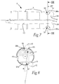
- the rearward end portion 6, see Fig 7 comprises a conical section 7, tapering away from the forward end portion 5, and an engagement section 8 located rearwards the conical section 7.
- the forward end portion 5 of the first tool part 1 is integrally formed with the rearward end portion 6 of the first tool part 1.
- the second tool part 2 comprises a conical recess 11 for receiving of the conical section 7 of the first tool part 1, see Figs 4 and 5 .
- the second tool part 2 may also comprise at least one cutting edge 12 as can be seen in Fig 1 .
- the cutting tool assembly is configured for machining of elongated holes, i.e. relatively long and thin holes, such as valve guides for internal combustion engines in the automotive industry, by means of the cutting edge 3 of the first tool part 1. Due to its elongated shape, the first tool part 1 is suitable for being introduced into the valve guide. In the same machining operation, and thus simultaneously, the cutting tool assembly may permit machining of the valve seat extending around the valve guide by means of the cutting edge 12 of the second tool part 2.
- the conical section 7 of the rearward end portion 6 of the first tool part 1 has a cone angle a, wherein 0.5° ⁇ ⁇ ⁇ 10°, preferably 0.5° ⁇ ⁇ ⁇ 7°, more preferably 0.5° ⁇ ⁇ ⁇ 4°, see Fig 7 .
- the conical recess 11 of the second tool part may have a cone angle of the same size as the cone angle a, as illustrated in Fig 6 .
- the cone angle ⁇ is thus relatively small, which means that the friction forces between the conical section 7 and the conical recess 11 may be significant.
- the small cone angle ⁇ implies that no axial stop is provided between the first tool part 1 and the second tool part 2.
- the rearward end portion 6 of the first tool part 1 comprises three axial grooves 13 extending along the conical section 7, see Figs 7 and 8 .
- the conical recess 11 of the second tool part 2 comprises three corresponding axial grooves 14, see Figs 3 and 6 , which are located opposite to a respective one of the grooves 13 when the first tool part 1 is mounted in the second tool part 2.
- a pin 15 is provided in the each of the axial grooves 14 of the second tool part 2 and co-operates with the opposite axial groove 13 of the first tool part 1 to permit torque transmission between the second tool part 2 and the first tool part 1 when the first tool part 1 is mounted in the second tool part 2.
- the pins 15 are held in position in their respective axial groove 14 by means of an inner retaining ring 16, see Figs 4 and 5 .
- the second tool part 2 comprises a clamping device 20 located rearwards the conical recess 11 of the second tool part 2. More precisely, the clamping device 20 is provided in a transversal cavity 19 of the second tool part 2. In the embodiments disclosed, the transversal cavity 19 is provided rearwards and adjacent to the conical recess 11 and extends through the second tool part 2, i.e. all the way through the second tool part 2 as can be seen in Figs 4-6 .
- the clamping device 20 comprises a first clamp block 21, a second clamp block 22 and a differential screw 23.
- the differential screw 23 extends along a transversal axis y being perpendicular to the longitudinal axis x.
- the differential screw 23 engages the first and second clamp blocks 21 and 22.
- the differential screw 23 is configured the move the first and second clamp blocks 21 and 22 in parallel with the transversal axis y away from and towards each other.
- the first clamp block 21 comprises a threaded channel 21a extending in parallel with the transversal axis y through the first clamp block 21.
- the second clamp block 22 comprises a threaded channel 22a extending in parallel with the transversal axis y through the second clamp block 22.
- the differential screw 23 comprises a first threaded part 24, cooperating with the threaded channel 21a of the first clamp block 21, and a second threaded part 25, cooperating with the threaded channel 22a of the second clamp block 22.
- the first threaded part 24, as well as the threaded channel of the first clamp block 21, may be a left-handed thread and the second thread part 25, as well as the threaded channel of the second clamp block 22, may be a right-handed thread, or vice-versa.
- the differential screw 23 may comprise a restricted mid portion 26 located between the first threaded part 24 and the second threaded part 22.
- the restricted mid portion 26 has a smaller diameter than the first and second threaded parts 24 and 25.
- the differential screw 23 may also have at least one engagement insert 27 for receiving a tool for rotating the differential screw 23.
- one engagement insert 27 extends from a first end of the differential screw 23 inside the first threaded part 24. As can be seen from Fig 1 in combination with Figs 4-6 , the engagement insert 27 is easily accessible from outside the cutting tool assembly by a suitable tool.
- the first clamp block 21 and the second clamp block 22 comprise a respective engagement surface 21b and 22b, which are arranged to engage the engagement section 8 of the first tool part 1, when the conical section 7 is placed in the conical recess 11 of the second tool part 2, see Figs 6 , 10a and 10c .
- the first tool part 1 may be pulled into a holding position in the conical recess 11 of the second tool part 2 when the first and second clamp blocks 21, 22 are moved towards each other through rotation of the differential screw 23.
- the differential screw 23 protrudes rearwards from the first and second clamp blocks 21, 22 beyond the threaded channels 21b, 22b.
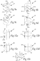
- the threaded channel 21a of the first clamp block 21 and the threaded channel 22a of the second clamp block 22 have a respective elongated opening 21c and 22c, see in particular Figs. 9a, 9c and 10e .
- the elongated opening 21c, 22c extend in parallel with the transversal axis through a rearward end of the first and second clamp blocks 21, 22, respectively.
- the differential screw 23 protrudes rearwards through the openings 21c, 22c, which permits to design the clamping device 20 with a short axial length.
- the transversal cavity 19 that houses the clamping device 20 may be formed by two overlapping holes that extend diametrically through the second tool part 2.
- a first rearward hole may house the protruding part of the differential screw 23 and a second forward hole may house the clamp blocks 21, 22.
- the first hole has a smaller diameter than the second hole.
- the central angle ⁇ of the threaded channel 22a of the second clamp block 22 may be equal to the central angle length ⁇ of the first clamp block 21.
- the central angle ⁇ should be great enough to ensure that the differential screw 23 is retained in the threaded channels 21a, 22a, but short enough to permit a short axial length and a compactness of the clamping device 20.
- an elastic retaining ring 28 may be provided and extend around the second tool part 2 and the first and second clamp blocks 21, 22, see Figs 1 , 4 , 5 and 12b .
- the retaining ring 28 may be provided in a circumferential groove 29 of the second tool part 2.
- the circumferential groove 29 may be axially located at the transversal cavity 19, in particular at a forward end of the transversal cavity 19 as can be seen in especially Figs. 11 and 12 .
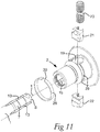
- the retaining ring 28 may be a kind of split ring with a short gap 30 between two adjacent ends of the retaining ring 28, see Fig 11 .
- the first clamp block 21 may comprise a recess 31 in a radially outer surface of the first clamp block 21.
- the recess 31 may be designed to receive a part of the retaining ring 28 when the first clamp block 21 is provided in the transversal cavity 19.
- the second clamp block 22 may comprise a recess 32 in a radially outer surface of the second clamp block 22.
- the recess 32 may be designed to receive an opposite part of the retaining ring 28 when the second clamp block 22 is provided in the transversal cavity 19.
- the recess 31 of the first clamp block 21 may, in contrast to the recess 32 of the second clam block 22, have a protrusion 33 that may be located at a central position of the recess 31.
- the protrusion 33 may be designed to extend into the gap 30 of the retaining ring 28, when the retaining ring 28 is provided in the circumferential groove 29.
- the engagement section 8 of the rearward end portion 6 of the first tool part 1 comprises a first transversal groove 36 and a second transversal groove 37, see in particular Figs 7 and 8 .
- the transversal groove 36, 37 are separated from and located diametrically opposite to each other.
- the transversal grooves 36, 37 may comprise a respective inclined forward surface 36a, 37a turned towards the conical section 7.
- the inclined forward surfaces 36a, 37 forms an angle of 40° to the transversal axis y as can be seen in Fig 7 .
- the transversal grooves 36, 37 may ensure a high strength of the engagement section 8. In particular, the strength may be improved in comparison to only one circumferential groove extending all the way around the engagement section.
- Each of the first and second transversal grooves 36, 37 may have a bottom line 36b, 37b being perpendicular to the longitudinal axis x when seen in a direction from the first transversal groove 36 to the second transversal groove 37.
- the bottom line 36b, 37b may be is convexly curved.
- the convexly curved bottom line 36b, 37b may contribute to further ensure the strength of the engagement section 8 of the first tool part 1 when large pulling forces are applied to the engagement section 8 and the first and second transversal grooves 36, 37.
- the bottom line 36b, 37b may have a radius R of curvature that is longer than a smallest radial distance from the bottom line 36b, 37b to the longitudinal axis x.
- the engagement surface 21b, 22b of the first and second clamp blocks 21, 22 may engage a respective one of the inclined forward surfaces 36a, 37a, as illustrated in Figs 4 and 5 .
- the engagement surfaces 21b, 22b are comprised by a respective recess 21d, 22d, see Fig 6 .
- Each recess 21d, 22d may have a mid plane forming an angle of about 40° to the transversal axis y.
- the engagement surfaces 21d, 22d may form an angle of about 15° to the mid plane.
- the engagement section 8 may comprise two inclined rearward surfaces 38, 39 turned away from the conical section 7, see Fig 7 .
- the inclined rearward surfaces 38, 39 are provided on a rearward end surface of the rearward end portion 6 of the first tool part 1.
- Each of the clamp blocks 21, 22 may also comprise a respective forward surface 21e, 22e turned towards an outer end of the conical recess 11.
- the forward surface 21e of the first clamp block 21 is located opposite to the engagement surface 21c in the recess 21d
- the forward surface 22e of the second clamp block 22 is located opposite to the engagement surface 22c in the recess 22d.
- the rearward surfaces 38 is configured to be engaged by the forward surface 21e of the first clamp block 21, and rearward surfaces 39 is configured to be engaged by the forward surface 22e of the second clamp block 22 when the first and second clamp blocks 21, 22 are moved away from each other, see Fig 5 , wherein the first tool part 1 may be pushed out of the holding position in the conical recess 11.
- the cutting tool assembly may also comprise a coolant system for the supply of coolant to the cutting edge 3.
- the coolant system comprises a first central channel 41 through the first tool part 1 and a second central channel 42 through the second tool part 2, see Fig 1 .
- the clamping device 20 may be configured to permit coolant to flow through the second central channel 42 into the first central channel 41 to an opening adjacent to the cutting edge 3, see Fig 2 , thereby bypassing the restricted mid portion 26 of the differential screw 23.
- the coolant system may also comprise a coolant conduit from the second central channel 42 to an opening adjacent to the cutting edge 12, see Fig 1 .
Landscapes
- Engineering & Computer Science (AREA)
- Mechanical Engineering (AREA)
- Milling Processes (AREA)
Abstract
Description
- The present invention refers generally to a cutting tool assembly, in particular a rotating cutting tool assembly configured for machining of elongated holes, i.e. relatively long and thin holes, such as valve guides for internal combustion engines in the automotive industry. The invention is however not limited to this specific application, but may be applied to the machining of any elongated holes. In particular, the present invention refers to a cutting tool assembly according to the pre-characterizing portion of
claim 1. -
DE 20 2015 104 652 discloses a rotating cutting tool assembly comprising a first tool part having a cutting edge, and a second tool part releasably holding the first tool part. The first tool part is elongated and extends along a longitudinal axis. The first tool part comprises a forward end portion comprising the cutting edge and a rearward end portion comprising a conical section, tapering away from the forward end portion, and an engagement section located rearwards the conical section. The second tool part comprises a conical recess receiving the conical section of the first tool part, and a clamping device located rearwards the conical recess, - The clamping device of
DE 20 2015 104 652 comprises a sleeve having a number of tongues extending in a longitudinal direction in a central bore of the second tool part. The tongues may grip the engagement section of the first tool part and may be pulled rearwards in order to secure the first tool part in the recess of the second tool part. The pulling movement of the sleeve and the first tool part is made from a rearward end of the second tool part, which means that the rearward end needs to be accessible. In practice the second tool part therefore needs to be released from the machine tool when the first tool part is to be exchanged or replaced. - A further disadvantage of prior art rotating cutting tool assembly is the relatively long axial length of the clamping device. The clamping device extends significantly rearwards in the tool holder, which increases the total length of the tool with negative implications on the usefulness of the tool.
- The purpose of the present invention is to overcome the disadvantages discussed above and to provide a cutting tool assembly that may be disassembled and assembled in an easy manner, and that may be designed with a short total length.
- This purpose is achieved by the cutting tool assembly initially defined, which is characterised in
- that the clamping device is provided in a transversal cavity of the second tool part and comprises a first clamp block, a second clamp block and a differential screw extending along a transversal axis and engaging the first and second clamp blocks, wherein the differential screw is configured to move the first and second clamp blocks in parallel with the transversal axis away from and towards each other,
- that the first and second clamp blocks comprise a respective engagement surface arranged to engage the engagement section of the first tool part, when the conical section is placed in the conical recess, in order to pull the first tool part into a holding position in the conical recess when the first and second clamp blocks are moved towards each other, and
- that each of the first and second clamp blocks comprises a respective threaded channel extending in parallel with the transversal axis and receiving the differential screw protruding rearwards from the first and second clamp blocks beyond the threaded channels.
- According to the invention, the differential screw of the clamping device may be accessible from the side of the second tool part, and may thus be manipulated and rotated in a clamping direction from the side of the second tool part to move the first and second clamp blocks to engage the engagement section of the first tool part. No access to the second tool part from behind is needed for the exchange of the first tool part. The second tool part may thus remain in the machine tool, or form an integrated part of the machine tool, during exchange of the first tool part. The exchange of the first tool part, for instance a reamer, may thus be made much quicker.
- Furthermore, the clamping device may have a significantly short axial length thanks to the configuration with the protruding differential screw, contributing to a compact and axially short design of the second tool part. The first and second clamp blocks may not have to extend axially beyond the differential screw.
- According to an embodiment of the invention, the transversal cavity of the second tool part extends in the transversal direction through the second tool part. The differential screw may thus be accessible from two opposite sides of the second tool part.
- According to an embodiment of the invention, the second tool part may comprise or constitute a tool holder, or may form an integrated part of a machine tool.
- According to an embodiment of the invention, the first tool part may be elongated. The first tool part may thus have an axial length that is at least 2 or 3 or 4 or 5 or 6 or 7 or 8 or 9 of 10 or more times the cutting diameter Dc. The cutting diameter Dc is defined as two times the distance between the longitudinal axis and the cutting edge of the first tool part.
- According to an embodiment of the invention, each of the threaded channels has an elongated opening, which extends in parallel with the transversal axis through a rearward end of the first and second clamp blocks, respectively, wherein the differential screw protrudes rearwards through the openings.
- According to an embodiment of the invention, each of the threaded channels, seen in a plane perpendicular to the transversal axis, has a central angle β having a first ray that intersects a first edge of the elongated opening and a second ray that intersects a second edge of the elongated opening, and wherein 180° < β < 360°. A vertex of the angle β is situated on a central axis of the threaded channel. This configuration of the channels, where the central angle is 180° < β < 360°, may contribute to a significant shortening of the length of the first and second clamp blocks in comparison with clamp blocks having circular cylindrical threaded channels with a full peripheral length, i.e. threaded channels where the angle β is equal to 360°. More preferably, 200° ≤ β ≤ 330°, even more preferably 220° ≤ β ≤ 300° and most preferably β = 240°. When 200° ≤ β, assembling of the differential screw into the clamp blocks is facilitated. When 220° ≤ β, assembling of the clamping device into the second tool part is significantly easier. When β ≤ 330°, the clamp blocks are shortened more significantly, and the manufacturing is facilitated. When β ≤ 300°, a width of the elongated opening is easier to control.
- According to an embodiment of the invention, the clamping device comprises an elastic retaining ring extending around the second tool part and the first and second clamp blocks, wherein the retaining ring retains the first and second clamp blocks in the transversal cavity of the second tool part. This is particularly advantageous when the transversal cavity extends through the second tool part, but also when the transversal cavity extends through only one side of the second tool part.
- According to an embodiment of the invention, the retaining ring is provided in a circumferential groove of the second tool part. The circumferential groove may extend over the transversal cavity.
- According to an embodiment of the invention, the differential screw comprises a first threaded part cooperating with the threaded channel of the first clamp block and a second threaded part cooperating with the threaded channel of the second clamp block, wherein at least one of the first threaded part and the second threaded part protrudes rearwards from the respective first and second clamp block beyond the respective threaded channel. At least one of the first threaded part and the second threaded part may thus have a segment located rearwards the respective clamp block. The first and second clamp block may thus have a shorter axial length as explained above. Advantageously, both the first threaded part and the second threaded part protrudes beyond the respective threaded channel.
- According to an embodiment of the invention, the cutting tool assembly comprises a coolant system for the supply of coolant to the cutting edge, wherein the coolant system comprises a first central channel through the first tool part and a second central channel through the second tool part, wherein the clamping device and/or the transversal cavity is configured to permit coolant to flow through the second central channel into the first central channel. The coolant may thus bypass the differential screw, and preferably pass through a gap in the transversal cavity between the first and second clamp blocks. When seen in the direction of the transversal axis, the transversal cavity may have a shape that is concentric to the shape of the clamping device. Thanks to this, a loss of coolant is minimized but also contamination of the clamping device is minimized when machining without coolant. Sealing between the clamping device and the transversal cavity may also be provided, or sealing of the transversal cavity. Proper cooling of the cutting edge and the workpiece may thus be ensured.
- According to an embodiment of the invention, the differential screw comprises a restricted mid portion between the first threaded part and the second threaded part, wherein the coolant is permitted to flow through the second central channel into the first central channel thereby bypassing the restricted mid portion of the differential screw.
- According to an embodiment of the invention, the engagement section comprises a first transversal groove and a second transversal groove, which are separated from and located diametrically opposite to each other and comprise a respective inclined forward surface turned towards the conical section. By the provision of such transversal grooves, a high strength of the engagement section may be ensured. In particular, the strength may be improved in comparison to only one circumferential groove extending all the way around the engagement section.
- According to an embodiment of the invention, the first and second clamp blocks comprise a respective engagement surface engaging a respective one of the inclined forward surfaces in order to pull the first tool part into the holding position in the conical recess when the first and second clamp blocks are moved towards each other. The engagement surfaces of the first and second clamp blocks may be inclined and turned rearwards towards the differential screw. Advantageously, the engagement surfaces of the first and second clamp blocks may be inclined with an angle of inclination that corresponds to an angle of inclination of the inclined forward surfaces of the respective transversal groove.
- According to an embodiment of the invention, each of the first and second transversal grooves has a bottom line being perpendicular to the longitudinal axis when seen in a direction from the first transversal groove to the second transversal groove.
- According to an embodiment of the invention, the bottom line is convexly curved. The convexly curved bottom line may contribute to further ensure the strength of the engagement section of the first tool part.
- According to an embodiment of the invention, the bottom line has a radius of curvature being longer than a smallest radial distance from the bottom line to the longitudinal axis.
- According to an embodiment of the invention, the engagement section comprises two inclined rearward surfaces turned away from the conical section and configured to be engaged by a respective forward surface of the first and second clamp blocks in order to push the first tool part out of the holding position in the conical recess when the first and second clamp blocks are moved away from each other. By rotating the differential screw in a releasing direction, being opposite to the clamping direction, the first tool part may thus be pushed out of the conical recess of the second tool part against the friction forces between the conical section and the conical recess. These forces may be significant, especially in case of a small cone angle of the conical section of the first tool part. The inclined rearward surfaces may be positioned opposite to a respective one of the inclined forward surfaces of the first and second transversal grooves, and may be comprised by a rearward end side of the engagement section of the first tool part. The configuration with the two transversal grooves may be particularly advantageous in combination with this function given by the inclined rearward surfaces and the respective forward surface of the first and second clamp blocks, since loss of chips or splinter from the engagement section may be avoided or may occur less frequently in comparison with a configuration with only one circumferential groove extending all the way around the engagement section.
- According to an embodiment of the invention, the conical section of the rearward portion of the first tool part has a cone angle a, and wherein 0.5° ≤ α ≤ 10°.
- According to an embodiment of the invention, the rearward end portion of the first tool part comprises at least one axial groove extending along the conical section, wherein the conical recess of the second tool part comprises at least one axial groove, wherein a pin is provided in the at least one axial groove of the second tool part and arranged to co-operate with the at least one axial groove of the first tool part to permit torque transmission between the second tool part and the first tool part when the first tool part is mounted in the second tool part. A central axis of the at least one pin is preferably parallel with the longitudinal axis of the first tool part. Also, a direction of extension of the at least one axial groove extending along the conical section is preferably parallel with the longitudinal axis of the first tool part. Advantageously, the rearward end portion of the first tool part comprises three axial grooves cooperating with a respective pin arranged in a respective axial groove of the conical recess of the second tool part.
- According to an embodiment of the invention, the forward end portion of the first tool part is integrally formed with the rearward end portion of the first tool part. The forward end portion may comprise an elongated tool shaft.
- According to an embodiment of the invention, the first tool part comprises, or constitutes, a reamer.
- According to an embodiment of the invention, the second tool part comprises at least one cutting edge. The cutting edge of the second tool part may be used for machining a valve seat of an internal combustion engine whereas the cutting edge of the first tool part may be used for simultaneous machining of the valve guide of the internal combustion engine. The cutting tool assembly is preferably a tool for valve seats and valve guides machining.
- The present invention will now be explained more closely by means of a description of various embodiments and with reference to the drawings attached hereto.
- Fig 1
- discloses a perspective view of a disassembled cutting tool assembly according to an embodiment of the invention.
- Fig 2
- discloses a perspective view of a cutting edge of a first tool part of the cutting tool assembly.
- Fig 3
- discloses front view of the cutting tool assembly in an assembled state, with a transversal section through the first tool part.
- Fig 4
- discloses a longitudinal section of a clamping device of the cutting tool assembly during a clamping operation.
- Fig 5
- discloses a longitudinal section of the clamping device during a releasing operation.
- Fig 6
- discloses an exploded longitudinal section of the clamping device in
Figs 4 and 5 . - Fig 7
- discloses a side view of a rear portion of the first tool part of the cutting tool assembly.
- Fig 8
- discloses section along the line VIII-VIII in
Fig 7 . - Fig 9a
- discloses a perspective view of a first clamp block of the clamping device.
- Fig 9b
- discloses another perspective view of the first clamp block.
- Fig 9c
- discloses a perspective view of a second clamp block of the clamping device.
- Fig 9d
- discloses another perspective view of the second clamp block.
- Fig 10a
- discloses a side view of the first clamp block in
Fig 9a . - Fig 10b
- discloses a front view of the first clamp block in
Fig 9a . - Fig 10c
- discloses a side view of the second clamp block in
Fig 9b . - Fig 10d
- discloses a front view of the second clamp block in
Fig 9b . - Fig 10e
- discloses a top view of the first clamp block in
Fig 9a . - Fig 11
- discloses an exploded perspective view of the clamping device.
- Fig 12
- discloses a top view of the clamping device in a disassembled state.
- Fig 12a
- discloses a top view of the clamping device in a partly assembled state.
- Fig 12b
- discloses a top view of the clamping device in an assembled state.
-
Fig 1 discloses a cutting tool assembly, in particular a rotating cutting tool assembly to be received by a machine tool (not disclosed) for rotating the cutting tool assembly. It should be noted that the cutting tool assembly could also be used as a stationery tool wherein the workpiece (not disclosed) is moved, for instance rotated. - The cutting tool assembly comprises a
first tool part 1 and asecond tool part 2. In the embodiments disclosed, thefirst tool part 1 constitutes or comprises a reamer having at least onecutting edge 3, see alsoFig 2 . Thesecond tool part 2 constitutes or comprises a tool holder configured for releasably holding of thefirst tool part 1. - In the embodiments disclosed, the
second tool part 2 comprises arear engagement portion 4 to be received in the machine tool. Alternatively, thesecond tool part 2 may form an integrated part of the machine tool. - When the cutting tool assembly is assembled, the
first tool part 1 and the second tool part extend along a longitudinal axis x. Thefirst tool part 1 is elongated, and may have an axial length that is at least 2 or 3 or 4 or 5 or 6 or 7 or 8 or 9 or 10 or more times the cutting diameter. The cutting diameter is defined as two times the distance between the longitudinal axis x and thecutting edge 3 of thefirst tool part 1. - The
first tool part 1 comprises aforward end portion 5 comprising thecutting edge 3 and arearward end portion 6. Theforward end portion 5 comprises or forms an elongated tool shaft carrying thecutting edge 3. Thecutting edge 3 may be comprised by a hard metal insert seated in a seat of theforward end portion 5, e.g. removably attached or soldered in the seat, or may be integrally formed with theforward end portion 5. - The
rearward end portion 6, seeFig 7 , comprises aconical section 7, tapering away from theforward end portion 5, and anengagement section 8 located rearwards theconical section 7. - In the embodiments disclosed, the
forward end portion 5 of thefirst tool part 1 is integrally formed with therearward end portion 6 of thefirst tool part 1. - The
second tool part 2 comprises aconical recess 11 for receiving of theconical section 7 of thefirst tool part 1, seeFigs 4 and 5 . Thesecond tool part 2 may also comprise at least onecutting edge 12 as can be seen inFig 1 . - The cutting tool assembly is configured for machining of elongated holes, i.e. relatively long and thin holes, such as valve guides for internal combustion engines in the automotive industry, by means of the
cutting edge 3 of thefirst tool part 1. Due to its elongated shape, thefirst tool part 1 is suitable for being introduced into the valve guide. In the same machining operation, and thus simultaneously, the cutting tool assembly may permit machining of the valve seat extending around the valve guide by means of thecutting edge 12 of thesecond tool part 2. - The
conical section 7 of therearward end portion 6 of thefirst tool part 1 has a cone angle a, wherein 0.5° ≤ α ≤ 10°, preferably 0.5° ≤ α ≤ 7°, more preferably 0.5° ≤ α ≤ 4°, seeFig 7 . Theconical recess 11 of the second tool part may have a cone angle of the same size as the cone angle a, as illustrated inFig 6 . - The cone angle α is thus relatively small, which means that the friction forces between the
conical section 7 and theconical recess 11 may be significant. The small cone angle α implies that no axial stop is provided between thefirst tool part 1 and thesecond tool part 2. - In the embodiments disclosed, the
rearward end portion 6 of thefirst tool part 1 comprises threeaxial grooves 13 extending along theconical section 7, seeFigs 7 and 8 . Theconical recess 11 of thesecond tool part 2 comprises three correspondingaxial grooves 14, seeFigs 3 and6 , which are located opposite to a respective one of thegrooves 13 when thefirst tool part 1 is mounted in thesecond tool part 2. Apin 15 is provided in the each of theaxial grooves 14 of thesecond tool part 2 and co-operates with the oppositeaxial groove 13 of thefirst tool part 1 to permit torque transmission between thesecond tool part 2 and thefirst tool part 1 when thefirst tool part 1 is mounted in thesecond tool part 2. Thepins 15 are held in position in their respectiveaxial groove 14 by means of aninner retaining ring 16, seeFigs 4 and 5 . - The
second tool part 2 comprises aclamping device 20 located rearwards theconical recess 11 of thesecond tool part 2. More precisely, the clampingdevice 20 is provided in atransversal cavity 19 of thesecond tool part 2. In the embodiments disclosed, thetransversal cavity 19 is provided rearwards and adjacent to theconical recess 11 and extends through thesecond tool part 2, i.e. all the way through thesecond tool part 2 as can be seen inFigs 4-6 . - The clamping
device 20 comprises afirst clamp block 21, asecond clamp block 22 and adifferential screw 23. Thedifferential screw 23 extends along a transversal axis y being perpendicular to the longitudinal axis x. - The
differential screw 23 engages the first and second clamp blocks 21 and 22. Thedifferential screw 23 is configured the move the first and second clamp blocks 21 and 22 in parallel with the transversal axis y away from and towards each other. - The
first clamp block 21 comprises a threadedchannel 21a extending in parallel with the transversal axis y through thefirst clamp block 21. Thesecond clamp block 22 comprises a threadedchannel 22a extending in parallel with the transversal axis y through thesecond clamp block 22. - The
differential screw 23 comprises a first threadedpart 24, cooperating with the threadedchannel 21a of thefirst clamp block 21, and a second threadedpart 25, cooperating with the threadedchannel 22a of thesecond clamp block 22. The first threadedpart 24, as well as the threaded channel of thefirst clamp block 21, may be a left-handed thread and thesecond thread part 25, as well as the threaded channel of thesecond clamp block 22, may be a right-handed thread, or vice-versa. - Furthermore, the
differential screw 23 may comprise a restrictedmid portion 26 located between the first threadedpart 24 and the second threadedpart 22. In the embodiments disclosed, the restrictedmid portion 26 has a smaller diameter than the first and second threadedparts - The
differential screw 23 may also have at least oneengagement insert 27 for receiving a tool for rotating thedifferential screw 23. In the embodiments disclosed, oneengagement insert 27 extends from a first end of thedifferential screw 23 inside the first threadedpart 24. As can be seen fromFig 1 in combination withFigs 4-6 , theengagement insert 27 is easily accessible from outside the cutting tool assembly by a suitable tool. - The
first clamp block 21 and thesecond clamp block 22 comprise arespective engagement surface engagement section 8 of thefirst tool part 1, when theconical section 7 is placed in theconical recess 11 of thesecond tool part 2, seeFigs 6 ,10a and 10c . Thefirst tool part 1 may be pulled into a holding position in theconical recess 11 of thesecond tool part 2 when the first and second clamp blocks 21, 22 are moved towards each other through rotation of thedifferential screw 23. - As can be seen in
Figs 4-6 ,11 ,12, 12a and 12b , thedifferential screw 23 protrudes rearwards from the first and second clamp blocks 21, 22 beyond the threadedchannels - In the embodiments disclosed, the threaded
channel 21a of thefirst clamp block 21 and the threadedchannel 22a of thesecond clamp block 22 have a respectiveelongated opening Figs. 9a, 9c and 10e . Theelongated opening differential screw 23 protrudes rearwards through theopenings clamping device 20 with a short axial length. As can be seen inFig 12 , thetransversal cavity 19 that houses the clampingdevice 20 may be formed by two overlapping holes that extend diametrically through thesecond tool part 2. A first rearward hole may house the protruding part of thedifferential screw 23 and a second forward hole may house the clamp blocks 21, 22. The first hole has a smaller diameter than the second hole. - As can be seen in
Fig 10e , each of the threadedchannels elongated opening elongated opening channel 22a of thesecond clamp block 22 may be equal to the central angle length β of thefirst clamp block 21. - The central angle β should be great enough to ensure that the
differential screw 23 is retained in the threadedchannels clamping device 20. - In order to retain the
clamping device 20 in thetransversal cavity 19 of thesecond tool part 2, anelastic retaining ring 28 may be provided and extend around thesecond tool part 2 and the first and second clamp blocks 21, 22, seeFigs 1 ,4 ,5 and12b . The retainingring 28 may be provided in acircumferential groove 29 of thesecond tool part 2. Thecircumferential groove 29 may be axially located at thetransversal cavity 19, in particular at a forward end of thetransversal cavity 19 as can be seen in especiallyFigs. 11 and12 . The retainingring 28 may be a kind of split ring with ashort gap 30 between two adjacent ends of the retainingring 28, seeFig 11 . - The
first clamp block 21 may comprise arecess 31 in a radially outer surface of thefirst clamp block 21. Therecess 31 may be designed to receive a part of the retainingring 28 when thefirst clamp block 21 is provided in thetransversal cavity 19. - In the same way, the
second clamp block 22 may comprise arecess 32 in a radially outer surface of thesecond clamp block 22. Therecess 32 may be designed to receive an opposite part of the retainingring 28 when thesecond clamp block 22 is provided in thetransversal cavity 19. - The
recess 31 of thefirst clamp block 21 may, in contrast to therecess 32 of thesecond clam block 22, have aprotrusion 33 that may be located at a central position of therecess 31. Theprotrusion 33 may be designed to extend into thegap 30 of the retainingring 28, when the retainingring 28 is provided in thecircumferential groove 29. - In the embodiments disclosed, the
engagement section 8 of therearward end portion 6 of thefirst tool part 1 comprises a firsttransversal groove 36 and a secondtransversal groove 37, see in particularFigs 7 and 8 . Thetransversal groove transversal grooves forward surface conical section 7. In the embodiments disclosed, theinclined forward surfaces Fig 7 . Thetransversal grooves engagement section 8. In particular, the strength may be improved in comparison to only one circumferential groove extending all the way around the engagement section. - Each of the first and second
transversal grooves bottom line transversal groove 36 to the secondtransversal groove 37. As has been illustrated inFig 8 , thebottom line bottom line engagement section 8 of thefirst tool part 1 when large pulling forces are applied to theengagement section 8 and the first and secondtransversal grooves bottom line bottom line - In the embodiments disclosed, the
engagement surface Figs 4 and 5 . The engagement surfaces 21b, 22b are comprised by arespective recess Fig 6 . Eachrecess - When the first and second clamp blocks 21, 22 are moved towards each other through the rotation of the
differential screw 23, seeFig 4 , theengagement surface 21b of thefirst clamp block 21 engages the inclinedforward surface 36a of the firsttransversal groove 36, and theengagement surface 22b engages the inclinedforward surface 37a of the secondtransversal groove 37, wherein further moving of the first and second clamp blocks 21, 22 may pull thefirst tool part 1 into the holding position in theconical recess 11. - Furthermore, the
engagement section 8 may comprise two inclined rearward surfaces 38, 39 turned away from theconical section 7, seeFig 7 . In the embodiments disclosed, the inclined rearward surfaces 38, 39 are provided on a rearward end surface of therearward end portion 6 of thefirst tool part 1. - Each of the clamp blocks 21, 22 may also comprise a respective
forward surface conical recess 11. In the embodiments disclosed, theforward surface 21e of thefirst clamp block 21 is located opposite to theengagement surface 21c in therecess 21d, and theforward surface 22e of thesecond clamp block 22 is located opposite to theengagement surface 22c in therecess 22d. - The rearward surfaces 38 is configured to be engaged by the
forward surface 21e of thefirst clamp block 21, and rearward surfaces 39 is configured to be engaged by theforward surface 22e of thesecond clamp block 22 when the first and second clamp blocks 21, 22 are moved away from each other, seeFig 5 , wherein thefirst tool part 1 may be pushed out of the holding position in theconical recess 11. - The cutting tool assembly may also comprise a coolant system for the supply of coolant to the
cutting edge 3. The coolant system comprises a firstcentral channel 41 through thefirst tool part 1 and a secondcentral channel 42 through thesecond tool part 2, seeFig 1 . The clampingdevice 20 may be configured to permit coolant to flow through the secondcentral channel 42 into the firstcentral channel 41 to an opening adjacent to thecutting edge 3, seeFig 2 , thereby bypassing the restrictedmid portion 26 of thedifferential screw 23. - The coolant system may also comprise a coolant conduit from the second
central channel 42 to an opening adjacent to thecutting edge 12, seeFig 1 . - The present invention is not limited to the embodiments disclosed but may be varied and modified within the scope of the following claims.
Claims (18)
- A cutting tool assembly, preferably a rotating cutting tool assembly, comprising a first tool part (1) having at least one cutting edge (3), and a second tool part (2) for releasably holding of the first tool part (1),
the first tool part (1) extending along a longitudinal axis (x), wherein the first tool part (1) comprises a forward end portion (5) comprising the at least one cutting edge (3) and a rearward end portion (6) comprising a conical section (7), tapering away from the forward end portion (5), and an engagement section (8) located rearwards the conical section (7),
the second tool part (2) comprising a conical recess (11) for receiving of the conical section (7) of the first tool part (1), and a clamping device (20) located rearwards the conical recess (11),
characterized inthat the clamping device (20) is provided in a transversal cavity (19) of the second tool part (2) and comprises a first clamp block (21), a second clamp block (22) and a differential screw (23) extending along a transversal axis (y) and engaging the first and second clamp blocks (21, 22), wherein the differential screw (23) is configured to move the first and second clamp blocks (21, 22) in parallel with the transversal axis (y) away from and towards each other,that the first and second clamp blocks (21, 22) comprise a respective engagement surface (21b, 22b) arranged to engage the engagement section (8) of the first tool part (1), when the conical section (7) is placed in the conical recess (11), in order to pull the first tool part (1) into a holding position in the conical recess (11) when the first and second clamp blocks (21, 22) are moved towards each other, andthat each of the first and second clamp blocks (21, 22) comprises a respective threaded channel (21a, 22a) extending in parallel with the transversal axis (y) and receiving the differential screw (23) protruding rearwards from the first and second clamp blocks (21, 22) beyond the threaded channels (21a, 22a). - The cutting tool assembly according to claim 1, wherein each of the threaded channels (21a, 22a) has an elongated opening (21c, 22c), which extends in parallel with the transversal axis (y) through a rearward end of the first and second clamp blocks (21, 22), respectively, and wherein the differential screw (23) protrudes rearwards through the openings (21c, 22c).
- The cutting tool assembly according to any one of claims 1 and 2, wherein, seen in a plane perpendicular to the transversal axis (y), each of the threaded channels (21a, 22a) has a central angle β having a first ray that intersects a first edge of the elongated opening (21c, 22c) and a second ray that intersects a second edge of the elongated opening (21c, 22c), and wherein 180° < β < 360°.
- The cutting tool assembly according to any one of the preceding claims, wherein the clamping device (20) comprises an elastic retaining ring (28) extending around the second tool part (2) and the first and second clamp blocks (21, 22), and wherein the retaining ring (28) retains the first and second clamp blocks (21, 22) in the transversal cavity (19) of the second tool part (2).
- The cutting tool assembly according to any one of the preceding claims, wherein the differential screw (23) comprises a first threaded part (24) cooperating with the threaded channel (21a) of the first clamp block (21) and a second threaded part (25) cooperating with the threaded channel (22a) of the second clamp block (22), and wherein at least one of the first threaded part (24) and the second threaded part (25) protrudes rearwards from the respective first and second clamp block (21, 22) beyond the respective threaded channel (21a, 22a).
- The cutting tool assembly according to any one of the preceding claims, wherein the cutting tool assembly comprises a coolant system for the supply of coolant to the cutting edge (3, 12), wherein the coolant system comprises a first central channel (41) through the first tool part (1) and a second central channel (42) through the second tool part (2), and wherein the clamping device (20) and/or the transversal cavity (19) is configured to permit coolant to flow through the second central channel (42) into the first central channel (41).
- The cutting tool assembly according to claim 6, wherein the differential screw (23) comprises a restricted mid portion (26) between the first threaded part (24) and the second threaded part (22), and wherein the coolant is permitted to flow through the second central channel (42) into the first central channel (41) thereby bypassing the restricted mid portion (26) of the differential screw (23).
- The cutting tool assembly according to any one of the preceding claims, wherein the engagement section (8) comprises a first transversal groove (36) and a second transversal groove (37), which are separated from and located diametrically opposite to each other and comprise a respective inclined forward surface (36a, 37a) turned towards the conical section (7).
- The cutting tool assembly according to claim 8, wherein the first and second clamp blocks (21, 22) comprise a respective engagement surface (21b, 22b) engaging a respective one of the inclined forward surfaces (36a, 37a) in order to pull the first tool part (1) into the holding position in the conical recess (11) when the first and second clamp blocks (21, 22) are moved towards each other.
- The cutting tool assembly according to any one of claims 8 and 9, wherein each of the first and second transversal grooves (36, 37) has a bottom line (36b, 37b) being perpendicular to the longitudinal axis (x) when seen in a direction from the first transversal groove (36) to the second transversal groove (37).
- The cutting tool assembly according to claim 10, wherein the bottom line (36b, 37b) is convexly curved.
- The cutting tool assembly according to claim 11, wherein the bottom line (36b, 37b) has a radius (R) of curvature being longer than a smallest radial distance from the bottom line (36b, 37b) to the longitudinal axis (x).
- The cutting tool assembly according to any one of the preceding claims, wherein the engagement section (8) comprises two inclined rearward surfaces (38, 39) turned away from the conical section (7) and configured to be engaged by a respective forward surface (21e, 22e) of the first and second clamp blocks (21, 22) in order to push the first tool part (1) out of the holding position in the conical recess (11) when the first and second clamp blocks (21, 22) are moved away from each other.
- The cutting tool assembly according to any one of the preceding claims, wherein the conical section (7) of the rearward end portion (6) of the first tool part (1) has a cone angle a, and wherein 0.5° ≤ α ≤ 10°.
- The cutting tool assembly according to any one of the preceding claims, wherein the rearward end portion (6) of the first tool part (1) comprises at least one axial groove (13) extending along the conical section (7), wherein the conical recess (11) of the second tool part (2) comprises at least one axial groove (14), and wherein a pin (15) is provided in the at least one axial groove (14) of the second tool part (2) and arranged to co-operate with the at least one axial groove (13) of the first tool part (1) to permit torque transmission between the second tool part (2) and the first tool part (1) when the first tool part (1) is mounted in the second tool part (2).
- The cutting tool assembly according to any one of the preceding claims, wherein the forward end portion (5) of the first tool part (1) is integrally formed with the rearward end portion (6) of the first tool part (1).
- The cutting tool assembly according to any one of the preceding claims, wherein the first tool part (1) comprises a reamer.
- The cutting tool assembly according to any one of the preceding claims, wherein the second tool part (2) comprises at least one cutting edge (12).
Priority Applications (4)
| Application Number | Priority Date | Filing Date | Title |
|---|---|---|---|
| EP19210943.7A EP3825045B1 (en) | 2019-11-22 | 2019-11-22 | A cutting tool assembly |
| PCT/EP2020/074522 WO2021098998A1 (en) | 2019-11-22 | 2020-09-03 | A cutting tool assembly |
| US17/779,415 US12403535B2 (en) | 2019-11-22 | 2020-09-03 | Cutting tool assembly |
| CN202080080262.7A CN114728347B (en) | 2019-11-22 | 2020-09-03 | Cutting tool components |
Applications Claiming Priority (1)
| Application Number | Priority Date | Filing Date | Title |
|---|---|---|---|
| EP19210943.7A EP3825045B1 (en) | 2019-11-22 | 2019-11-22 | A cutting tool assembly |
Publications (2)
| Publication Number | Publication Date |
|---|---|
| EP3825045A1 true EP3825045A1 (en) | 2021-05-26 |
| EP3825045B1 EP3825045B1 (en) | 2022-08-10 |
Family
ID=68654387
Family Applications (1)
| Application Number | Title | Priority Date | Filing Date |
|---|---|---|---|
| EP19210943.7A Active EP3825045B1 (en) | 2019-11-22 | 2019-11-22 | A cutting tool assembly |
Country Status (4)
| Country | Link |
|---|---|
| US (1) | US12403535B2 (en) |
| EP (1) | EP3825045B1 (en) |
| CN (1) | CN114728347B (en) |
| WO (1) | WO2021098998A1 (en) |
Families Citing this family (1)
| Publication number | Priority date | Publication date | Assignee | Title |
|---|---|---|---|---|
| IT202100001679A1 (en) * | 2021-01-28 | 2022-07-28 | Officina Mecc Lombarda S R L | LOCKING DEVICE FOR PIECES SUITABLE TO BE WORKED ON MACHINE TOOLS |
Citations (4)
| Publication number | Priority date | Publication date | Assignee | Title |
|---|---|---|---|---|
| US2485799A (en) * | 1946-08-07 | 1949-10-25 | Giddings & Lewis | Toolhead |
| US2684249A (en) * | 1950-11-30 | 1954-07-20 | Giddings & Lewis | Toolhead and taper shank adapter |
| US20120200050A1 (en) * | 2006-06-19 | 2012-08-09 | Komet Group Gmbh. | Junction between two components of a rotating tool system |
| DE202015104652U1 (en) | 2015-09-02 | 2015-09-24 | Seco Tools Ab | Clamping device and combination of clamping device and tool |
Family Cites Families (12)
| Publication number | Priority date | Publication date | Assignee | Title |
|---|---|---|---|---|
| EP0193020B1 (en) * | 1985-03-01 | 1990-11-28 | Fried. Krupp Gesellschaft mit beschränkter Haftung | Tooling device with an exchangeable tool head |
| US4729702A (en) * | 1986-10-10 | 1988-03-08 | Carboloy Inc. | Clamping means for taper tool shanks |
| DE4314235A1 (en) * | 1993-04-30 | 1994-11-03 | Bilz Otto Werkzeug | Tool holder, especially quick change chuck |
| US7077608B2 (en) * | 2004-04-22 | 2006-07-18 | Parlec, Inc. | System for mounting a machine tool in a holder |
| DE102004026873A1 (en) * | 2004-06-02 | 2005-12-29 | NUBIUS GROUP Präzisionswerkzeuge GmbH | Cutting tool and cutting insert for a cutting tool |
| DE102006043733A1 (en) * | 2005-09-13 | 2007-03-22 | Komet Group Holding Gmbh | Device for coupling two workpiece parts e.g. machine spindles comprises a fixing pin arranged on the first workpiece part, a sleeve arranged on the second workpiece part and a clamping mechanism for drawing the fixing pin into the sleeve |
| DE202007014300U1 (en) * | 2007-04-21 | 2007-12-13 | Kennametal Inc. | Clamping device for a tool system |
| US8033766B2 (en) * | 2008-05-09 | 2011-10-11 | Kennametal Inc. | Tool holder with ball clamping mechanism |
| EP2435202B1 (en) * | 2009-05-26 | 2013-08-14 | GKN Aerospace Sweden AB | A holder for a cutting tool, a cutting tool and a cutting insert |
| EP2987573B1 (en) * | 2014-08-19 | 2020-12-16 | Sandvik Intellectual Property AB | A clamping device |
| EP3144086B1 (en) * | 2015-09-15 | 2018-05-09 | Sandvik Intellectual Property AB | A tool body and a turning tool for grooving operations |
| EP3560639A1 (en) * | 2018-04-27 | 2019-10-30 | AB Sandvik Coromant | A clamping device |
-
2019
- 2019-11-22 EP EP19210943.7A patent/EP3825045B1/en active Active
-
2020
- 2020-09-03 US US17/779,415 patent/US12403535B2/en active Active
- 2020-09-03 WO PCT/EP2020/074522 patent/WO2021098998A1/en not_active Ceased
- 2020-09-03 CN CN202080080262.7A patent/CN114728347B/en active Active
Patent Citations (4)
| Publication number | Priority date | Publication date | Assignee | Title |
|---|---|---|---|---|
| US2485799A (en) * | 1946-08-07 | 1949-10-25 | Giddings & Lewis | Toolhead |
| US2684249A (en) * | 1950-11-30 | 1954-07-20 | Giddings & Lewis | Toolhead and taper shank adapter |
| US20120200050A1 (en) * | 2006-06-19 | 2012-08-09 | Komet Group Gmbh. | Junction between two components of a rotating tool system |
| DE202015104652U1 (en) | 2015-09-02 | 2015-09-24 | Seco Tools Ab | Clamping device and combination of clamping device and tool |
Also Published As
| Publication number | Publication date |
|---|---|
| EP3825045B1 (en) | 2022-08-10 |
| CN114728347B (en) | 2025-02-25 |
| US20220410280A1 (en) | 2022-12-29 |
| US12403535B2 (en) | 2025-09-02 |
| WO2021098998A1 (en) | 2021-05-27 |
| CN114728347A (en) | 2022-07-08 |
Similar Documents
| Publication | Publication Date | Title |
|---|---|---|
| CN102079049B (en) | Tool holder and method for assembling the same | |
| EP2749367B1 (en) | Shrink fit tool holder | |
| KR100888041B1 (en) | Tool assembly | |
| EP2987574B1 (en) | A clamping device | |
| EP2987573B1 (en) | A clamping device | |
| JPH0435297B2 (en) | ||
| EP2987575B1 (en) | A clamping device | |
| US20180339383A1 (en) | Spindle apparatus and operating method thereof | |
| US20130320638A1 (en) | Work-holding chuck with quick-release jaws | |
| KR100254909B1 (en) | Keyless drill chuck | |
| EP3325198B1 (en) | Self-centering compact floating reamer holder | |
| EP3825045B1 (en) | A cutting tool assembly | |
| EP3782751A1 (en) | A milling cutter | |
| WO2020190726A1 (en) | Combination tool as well as drills for such a drilling/chamfering tool | |
| US6179303B1 (en) | Device for accomodating a tool or a support element in a machine tool or a spindle | |
| EP3750653B1 (en) | Clamping decvice for tool holder | |
| US5058467A (en) | Quick change collet stop | |
| US20240238879A1 (en) | Apparatus comprising a rotary tool, and method for attaching and detaching a cutting insert on such an apparatus | |
| US12220750B2 (en) | Clamping device for tool holder | |
| JP5326879B2 (en) | Cutting tools |
Legal Events
| Date | Code | Title | Description |
|---|---|---|---|
| PUAI | Public reference made under article 153(3) epc to a published international application that has entered the european phase |
Free format text: ORIGINAL CODE: 0009012 |
|
| STAA | Information on the status of an ep patent application or granted ep patent |
Free format text: STATUS: THE APPLICATION HAS BEEN PUBLISHED |
|
| AK | Designated contracting states |
Kind code of ref document: A1 Designated state(s): AL AT BE BG CH CY CZ DE DK EE ES FI FR GB GR HR HU IE IS IT LI LT LU LV MC MK MT NL NO PL PT RO RS SE SI SK SM TR |
|
| STAA | Information on the status of an ep patent application or granted ep patent |
Free format text: STATUS: REQUEST FOR EXAMINATION WAS MADE |
|
| 17P | Request for examination filed |
Effective date: 20211126 |
|
| RBV | Designated contracting states (corrected) |
Designated state(s): AL AT BE BG CH CY CZ DE DK EE ES FI FR GB GR HR HU IE IS IT LI LT LU LV MC MK MT NL NO PL PT RO RS SE SI SK SM TR |
|
| GRAP | Despatch of communication of intention to grant a patent |
Free format text: ORIGINAL CODE: EPIDOSNIGR1 |
|
| STAA | Information on the status of an ep patent application or granted ep patent |
Free format text: STATUS: GRANT OF PATENT IS INTENDED |
|
| RIC1 | Information provided on ipc code assigned before grant |
Ipc: B23B 29/04 20060101ALN20220318BHEP Ipc: B23B 31/00 20060101ALN20220318BHEP Ipc: B23D 77/00 20060101ALN20220318BHEP Ipc: B23C 3/05 20060101ALI20220318BHEP Ipc: B23B 31/107 20060101AFI20220318BHEP |
|
| INTG | Intention to grant announced |
Effective date: 20220425 |
|
| GRAS | Grant fee paid |
Free format text: ORIGINAL CODE: EPIDOSNIGR3 |
|
| GRAA | (expected) grant |
Free format text: ORIGINAL CODE: 0009210 |
|
| STAA | Information on the status of an ep patent application or granted ep patent |
Free format text: STATUS: THE PATENT HAS BEEN GRANTED |
|
| AK | Designated contracting states |
Kind code of ref document: B1 Designated state(s): AL AT BE BG CH CY CZ DE DK EE ES FI FR GB GR HR HU IE IS IT LI LT LU LV MC MK MT NL NO PL PT RO RS SE SI SK SM TR |
|
| REG | Reference to a national code |
Ref country code: AT Ref legal event code: REF Ref document number: 1510121 Country of ref document: AT Kind code of ref document: T Effective date: 20220815 Ref country code: CH Ref legal event code: EP |
|
| REG | Reference to a national code |
Ref country code: DE Ref legal event code: R096 Ref document number: 602019018048 Country of ref document: DE |
|
| REG | Reference to a national code |
Ref country code: IE Ref legal event code: FG4D |
|
| REG | Reference to a national code |
Ref country code: NL Ref legal event code: MP Effective date: 20220810 |
|
| REG | Reference to a national code |
Ref country code: LT Ref legal event code: MG9D |
|
| PG25 | Lapsed in a contracting state [announced via postgrant information from national office to epo] |
Ref country code: SE Free format text: LAPSE BECAUSE OF FAILURE TO SUBMIT A TRANSLATION OF THE DESCRIPTION OR TO PAY THE FEE WITHIN THE PRESCRIBED TIME-LIMIT Effective date: 20220810 Ref country code: RS Free format text: LAPSE BECAUSE OF FAILURE TO SUBMIT A TRANSLATION OF THE DESCRIPTION OR TO PAY THE FEE WITHIN THE PRESCRIBED TIME-LIMIT Effective date: 20220810 Ref country code: PT Free format text: LAPSE BECAUSE OF FAILURE TO SUBMIT A TRANSLATION OF THE DESCRIPTION OR TO PAY THE FEE WITHIN THE PRESCRIBED TIME-LIMIT Effective date: 20221212 Ref country code: NO Free format text: LAPSE BECAUSE OF FAILURE TO SUBMIT A TRANSLATION OF THE DESCRIPTION OR TO PAY THE FEE WITHIN THE PRESCRIBED TIME-LIMIT Effective date: 20221110 Ref country code: NL Free format text: LAPSE BECAUSE OF FAILURE TO SUBMIT A TRANSLATION OF THE DESCRIPTION OR TO PAY THE FEE WITHIN THE PRESCRIBED TIME-LIMIT Effective date: 20220810 Ref country code: LV Free format text: LAPSE BECAUSE OF FAILURE TO SUBMIT A TRANSLATION OF THE DESCRIPTION OR TO PAY THE FEE WITHIN THE PRESCRIBED TIME-LIMIT Effective date: 20220810 Ref country code: LT Free format text: LAPSE BECAUSE OF FAILURE TO SUBMIT A TRANSLATION OF THE DESCRIPTION OR TO PAY THE FEE WITHIN THE PRESCRIBED TIME-LIMIT Effective date: 20220810 Ref country code: FI Free format text: LAPSE BECAUSE OF FAILURE TO SUBMIT A TRANSLATION OF THE DESCRIPTION OR TO PAY THE FEE WITHIN THE PRESCRIBED TIME-LIMIT Effective date: 20220810 |
|
| REG | Reference to a national code |
Ref country code: AT Ref legal event code: MK05 Ref document number: 1510121 Country of ref document: AT Kind code of ref document: T Effective date: 20220810 |
|
| PG25 | Lapsed in a contracting state [announced via postgrant information from national office to epo] |
Ref country code: PL Free format text: LAPSE BECAUSE OF FAILURE TO SUBMIT A TRANSLATION OF THE DESCRIPTION OR TO PAY THE FEE WITHIN THE PRESCRIBED TIME-LIMIT Effective date: 20220810 Ref country code: IS Free format text: LAPSE BECAUSE OF FAILURE TO SUBMIT A TRANSLATION OF THE DESCRIPTION OR TO PAY THE FEE WITHIN THE PRESCRIBED TIME-LIMIT Effective date: 20221210 Ref country code: HR Free format text: LAPSE BECAUSE OF FAILURE TO SUBMIT A TRANSLATION OF THE DESCRIPTION OR TO PAY THE FEE WITHIN THE PRESCRIBED TIME-LIMIT Effective date: 20220810 Ref country code: GR Free format text: LAPSE BECAUSE OF FAILURE TO SUBMIT A TRANSLATION OF THE DESCRIPTION OR TO PAY THE FEE WITHIN THE PRESCRIBED TIME-LIMIT Effective date: 20221111 |
|
| PG25 | Lapsed in a contracting state [announced via postgrant information from national office to epo] |
Ref country code: SM Free format text: LAPSE BECAUSE OF FAILURE TO SUBMIT A TRANSLATION OF THE DESCRIPTION OR TO PAY THE FEE WITHIN THE PRESCRIBED TIME-LIMIT Effective date: 20220810 Ref country code: RO Free format text: LAPSE BECAUSE OF FAILURE TO SUBMIT A TRANSLATION OF THE DESCRIPTION OR TO PAY THE FEE WITHIN THE PRESCRIBED TIME-LIMIT Effective date: 20220810 Ref country code: ES Free format text: LAPSE BECAUSE OF FAILURE TO SUBMIT A TRANSLATION OF THE DESCRIPTION OR TO PAY THE FEE WITHIN THE PRESCRIBED TIME-LIMIT Effective date: 20220810 Ref country code: DK Free format text: LAPSE BECAUSE OF FAILURE TO SUBMIT A TRANSLATION OF THE DESCRIPTION OR TO PAY THE FEE WITHIN THE PRESCRIBED TIME-LIMIT Effective date: 20220810 Ref country code: CZ Free format text: LAPSE BECAUSE OF FAILURE TO SUBMIT A TRANSLATION OF THE DESCRIPTION OR TO PAY THE FEE WITHIN THE PRESCRIBED TIME-LIMIT Effective date: 20220810 Ref country code: AT Free format text: LAPSE BECAUSE OF FAILURE TO SUBMIT A TRANSLATION OF THE DESCRIPTION OR TO PAY THE FEE WITHIN THE PRESCRIBED TIME-LIMIT Effective date: 20220810 |
|
| REG | Reference to a national code |
Ref country code: DE Ref legal event code: R097 Ref document number: 602019018048 Country of ref document: DE |
|
| PG25 | Lapsed in a contracting state [announced via postgrant information from national office to epo] |
Ref country code: SK Free format text: LAPSE BECAUSE OF FAILURE TO SUBMIT A TRANSLATION OF THE DESCRIPTION OR TO PAY THE FEE WITHIN THE PRESCRIBED TIME-LIMIT Effective date: 20220810 Ref country code: EE Free format text: LAPSE BECAUSE OF FAILURE TO SUBMIT A TRANSLATION OF THE DESCRIPTION OR TO PAY THE FEE WITHIN THE PRESCRIBED TIME-LIMIT Effective date: 20220810 |
|
| PLBE | No opposition filed within time limit |
Free format text: ORIGINAL CODE: 0009261 |
|
| STAA | Information on the status of an ep patent application or granted ep patent |
Free format text: STATUS: NO OPPOSITION FILED WITHIN TIME LIMIT |
|
| PG25 | Lapsed in a contracting state [announced via postgrant information from national office to epo] |
Ref country code: MC Free format text: LAPSE BECAUSE OF FAILURE TO SUBMIT A TRANSLATION OF THE DESCRIPTION OR TO PAY THE FEE WITHIN THE PRESCRIBED TIME-LIMIT Effective date: 20220810 Ref country code: AL Free format text: LAPSE BECAUSE OF FAILURE TO SUBMIT A TRANSLATION OF THE DESCRIPTION OR TO PAY THE FEE WITHIN THE PRESCRIBED TIME-LIMIT Effective date: 20220810 |
|
| REG | Reference to a national code |
Ref country code: CH Ref legal event code: PL |
|
| P01 | Opt-out of the competence of the unified patent court (upc) registered |
Effective date: 20230603 |
|
| 26N | No opposition filed |
Effective date: 20230511 |
|
| REG | Reference to a national code |
Ref country code: BE Ref legal event code: MM Effective date: 20221130 |
|
| PG25 | Lapsed in a contracting state [announced via postgrant information from national office to epo] |
Ref country code: LI Free format text: LAPSE BECAUSE OF NON-PAYMENT OF DUE FEES Effective date: 20221130 Ref country code: CH Free format text: LAPSE BECAUSE OF NON-PAYMENT OF DUE FEES Effective date: 20221130 |
|
| PG25 | Lapsed in a contracting state [announced via postgrant information from national office to epo] |
Ref country code: SI Free format text: LAPSE BECAUSE OF FAILURE TO SUBMIT A TRANSLATION OF THE DESCRIPTION OR TO PAY THE FEE WITHIN THE PRESCRIBED TIME-LIMIT Effective date: 20220810 Ref country code: LU Free format text: LAPSE BECAUSE OF NON-PAYMENT OF DUE FEES Effective date: 20221122 |
|
| PG25 | Lapsed in a contracting state [announced via postgrant information from national office to epo] |
Ref country code: IE Free format text: LAPSE BECAUSE OF NON-PAYMENT OF DUE FEES Effective date: 20221122 |
|
| PG25 | Lapsed in a contracting state [announced via postgrant information from national office to epo] |
Ref country code: BE Free format text: LAPSE BECAUSE OF NON-PAYMENT OF DUE FEES Effective date: 20221130 |
|
| PG25 | Lapsed in a contracting state [announced via postgrant information from national office to epo] |
Ref country code: CY Free format text: LAPSE BECAUSE OF FAILURE TO SUBMIT A TRANSLATION OF THE DESCRIPTION OR TO PAY THE FEE WITHIN THE PRESCRIBED TIME-LIMIT Effective date: 20220810 |
|
| PG25 | Lapsed in a contracting state [announced via postgrant information from national office to epo] |
Ref country code: MK Free format text: LAPSE BECAUSE OF FAILURE TO SUBMIT A TRANSLATION OF THE DESCRIPTION OR TO PAY THE FEE WITHIN THE PRESCRIBED TIME-LIMIT Effective date: 20220810 Ref country code: HU Free format text: LAPSE BECAUSE OF FAILURE TO SUBMIT A TRANSLATION OF THE DESCRIPTION OR TO PAY THE FEE WITHIN THE PRESCRIBED TIME-LIMIT; INVALID AB INITIO Effective date: 20191122 |
|
| PG25 | Lapsed in a contracting state [announced via postgrant information from national office to epo] |
Ref country code: BG Free format text: LAPSE BECAUSE OF FAILURE TO SUBMIT A TRANSLATION OF THE DESCRIPTION OR TO PAY THE FEE WITHIN THE PRESCRIBED TIME-LIMIT Effective date: 20220810 |
|
| PG25 | Lapsed in a contracting state [announced via postgrant information from national office to epo] |
Ref country code: MT Free format text: LAPSE BECAUSE OF FAILURE TO SUBMIT A TRANSLATION OF THE DESCRIPTION OR TO PAY THE FEE WITHIN THE PRESCRIBED TIME-LIMIT Effective date: 20220810 |
|
| PG25 | Lapsed in a contracting state [announced via postgrant information from national office to epo] |
Ref country code: TR Free format text: LAPSE BECAUSE OF FAILURE TO SUBMIT A TRANSLATION OF THE DESCRIPTION OR TO PAY THE FEE WITHIN THE PRESCRIBED TIME-LIMIT Effective date: 20220810 |
|
| PGFP | Annual fee paid to national office [announced via postgrant information from national office to epo] |
Ref country code: DE Payment date: 20250930 Year of fee payment: 7 |
|
| PGFP | Annual fee paid to national office [announced via postgrant information from national office to epo] |
Ref country code: GB Payment date: 20251001 Year of fee payment: 7 |
|
| PGFP | Annual fee paid to national office [announced via postgrant information from national office to epo] |
Ref country code: IT Payment date: 20251022 Year of fee payment: 7 |
|
| PGFP | Annual fee paid to national office [announced via postgrant information from national office to epo] |
Ref country code: FR Payment date: 20251023 Year of fee payment: 7 |