EP3825031A1 - Turbine blade casting with strongback core - Google Patents
Turbine blade casting with strongback core Download PDFInfo
- Publication number
- EP3825031A1 EP3825031A1 EP20209332.4A EP20209332A EP3825031A1 EP 3825031 A1 EP3825031 A1 EP 3825031A1 EP 20209332 A EP20209332 A EP 20209332A EP 3825031 A1 EP3825031 A1 EP 3825031A1
- Authority
- EP
- European Patent Office
- Prior art keywords
- tip
- shelf
- core
- base surface
- Prior art date
- Legal status (The legal status is an assumption and is not a legal conclusion. Google has not performed a legal analysis and makes no representation as to the accuracy of the status listed.)
- Granted
Links
Images




Classifications
-
- B—PERFORMING OPERATIONS; TRANSPORTING
- B22—CASTING; POWDER METALLURGY
- B22C—FOUNDRY MOULDING
- B22C9/00—Moulds or cores; Moulding processes
- B22C9/22—Moulds for peculiarly-shaped castings
- B22C9/24—Moulds for peculiarly-shaped castings for hollow articles
-
- B—PERFORMING OPERATIONS; TRANSPORTING
- B22—CASTING; POWDER METALLURGY
- B22C—FOUNDRY MOULDING
- B22C21/00—Flasks; Accessories therefor
- B22C21/12—Accessories
- B22C21/14—Accessories for reinforcing or securing moulding materials or cores, e.g. gaggers, chaplets, pins, bars
-
- B—PERFORMING OPERATIONS; TRANSPORTING
- B22—CASTING; POWDER METALLURGY
- B22C—FOUNDRY MOULDING
- B22C7/00—Patterns; Manufacture thereof so far as not provided for in other classes
- B22C7/02—Lost patterns
-
- B—PERFORMING OPERATIONS; TRANSPORTING
- B22—CASTING; POWDER METALLURGY
- B22C—FOUNDRY MOULDING
- B22C9/00—Moulds or cores; Moulding processes
- B22C9/02—Sand moulds or like moulds for shaped castings
- B22C9/04—Use of lost patterns
-
- B—PERFORMING OPERATIONS; TRANSPORTING
- B22—CASTING; POWDER METALLURGY
- B22C—FOUNDRY MOULDING
- B22C9/00—Moulds or cores; Moulding processes
- B22C9/10—Cores; Manufacture or installation of cores
-
- B—PERFORMING OPERATIONS; TRANSPORTING
- B22—CASTING; POWDER METALLURGY
- B22C—FOUNDRY MOULDING
- B22C9/00—Moulds or cores; Moulding processes
- B22C9/10—Cores; Manufacture or installation of cores
- B22C9/103—Multipart cores
-
- B—PERFORMING OPERATIONS; TRANSPORTING
- B22—CASTING; POWDER METALLURGY
- B22C—FOUNDRY MOULDING
- B22C9/00—Moulds or cores; Moulding processes
- B22C9/10—Cores; Manufacture or installation of cores
- B22C9/106—Vented or reinforced cores
-
- F—MECHANICAL ENGINEERING; LIGHTING; HEATING; WEAPONS; BLASTING
- F01—MACHINES OR ENGINES IN GENERAL; ENGINE PLANTS IN GENERAL; STEAM ENGINES
- F01D—NON-POSITIVE DISPLACEMENT MACHINES OR ENGINES, e.g. STEAM TURBINES
- F01D5/00—Blades; Blade-carrying members; Heating, heat-insulating, cooling or antivibration means on the blades or the members
- F01D5/12—Blades
- F01D5/14—Form or construction
- F01D5/18—Hollow blades, i.e. blades with cooling or heating channels or cavities; Heating, heat-insulating or cooling means on blades
-
- F—MECHANICAL ENGINEERING; LIGHTING; HEATING; WEAPONS; BLASTING
- F01—MACHINES OR ENGINES IN GENERAL; ENGINE PLANTS IN GENERAL; STEAM ENGINES
- F01D—NON-POSITIVE DISPLACEMENT MACHINES OR ENGINES, e.g. STEAM TURBINES
- F01D5/00—Blades; Blade-carrying members; Heating, heat-insulating, cooling or antivibration means on the blades or the members
- F01D5/12—Blades
- F01D5/14—Form or construction
- F01D5/18—Hollow blades, i.e. blades with cooling or heating channels or cavities; Heating, heat-insulating or cooling means on blades
- F01D5/187—Convection cooling
-
- F—MECHANICAL ENGINEERING; LIGHTING; HEATING; WEAPONS; BLASTING
- F01—MACHINES OR ENGINES IN GENERAL; ENGINE PLANTS IN GENERAL; STEAM ENGINES
- F01D—NON-POSITIVE DISPLACEMENT MACHINES OR ENGINES, e.g. STEAM TURBINES
- F01D5/00—Blades; Blade-carrying members; Heating, heat-insulating, cooling or antivibration means on the blades or the members
- F01D5/12—Blades
- F01D5/14—Form or construction
- F01D5/20—Specially-shaped blade tips to seal space between tips and stator
-
- F—MECHANICAL ENGINEERING; LIGHTING; HEATING; WEAPONS; BLASTING
- F05—INDEXING SCHEMES RELATING TO ENGINES OR PUMPS IN VARIOUS SUBCLASSES OF CLASSES F01-F04
- F05D—INDEXING SCHEME FOR ASPECTS RELATING TO NON-POSITIVE-DISPLACEMENT MACHINES OR ENGINES, GAS-TURBINES OR JET-PROPULSION PLANTS
- F05D2230/00—Manufacture
- F05D2230/20—Manufacture essentially without removing material
- F05D2230/21—Manufacture essentially without removing material by casting
-
- F—MECHANICAL ENGINEERING; LIGHTING; HEATING; WEAPONS; BLASTING
- F05—INDEXING SCHEMES RELATING TO ENGINES OR PUMPS IN VARIOUS SUBCLASSES OF CLASSES F01-F04
- F05D—INDEXING SCHEME FOR ASPECTS RELATING TO NON-POSITIVE-DISPLACEMENT MACHINES OR ENGINES, GAS-TURBINES OR JET-PROPULSION PLANTS
- F05D2230/00—Manufacture
- F05D2230/20—Manufacture essentially without removing material
- F05D2230/21—Manufacture essentially without removing material by casting
- F05D2230/211—Manufacture essentially without removing material by casting by precision casting, e.g. microfusing or investment casting
-
- F—MECHANICAL ENGINEERING; LIGHTING; HEATING; WEAPONS; BLASTING
- F05—INDEXING SCHEMES RELATING TO ENGINES OR PUMPS IN VARIOUS SUBCLASSES OF CLASSES F01-F04
- F05D—INDEXING SCHEME FOR ASPECTS RELATING TO NON-POSITIVE-DISPLACEMENT MACHINES OR ENGINES, GAS-TURBINES OR JET-PROPULSION PLANTS
- F05D2240/00—Components
- F05D2240/20—Rotors
- F05D2240/30—Characteristics of rotor blades, i.e. of any element transforming dynamic fluid energy to or from rotational energy and being attached to a rotor
- F05D2240/305—Characteristics of rotor blades, i.e. of any element transforming dynamic fluid energy to or from rotational energy and being attached to a rotor related to the pressure side of a rotor blade
-
- F—MECHANICAL ENGINEERING; LIGHTING; HEATING; WEAPONS; BLASTING
- F05—INDEXING SCHEMES RELATING TO ENGINES OR PUMPS IN VARIOUS SUBCLASSES OF CLASSES F01-F04
- F05D—INDEXING SCHEME FOR ASPECTS RELATING TO NON-POSITIVE-DISPLACEMENT MACHINES OR ENGINES, GAS-TURBINES OR JET-PROPULSION PLANTS
- F05D2240/00—Components
- F05D2240/20—Rotors
- F05D2240/30—Characteristics of rotor blades, i.e. of any element transforming dynamic fluid energy to or from rotational energy and being attached to a rotor
- F05D2240/307—Characteristics of rotor blades, i.e. of any element transforming dynamic fluid energy to or from rotational energy and being attached to a rotor related to the tip of a rotor blade
-
- F—MECHANICAL ENGINEERING; LIGHTING; HEATING; WEAPONS; BLASTING
- F05—INDEXING SCHEMES RELATING TO ENGINES OR PUMPS IN VARIOUS SUBCLASSES OF CLASSES F01-F04
- F05D—INDEXING SCHEME FOR ASPECTS RELATING TO NON-POSITIVE-DISPLACEMENT MACHINES OR ENGINES, GAS-TURBINES OR JET-PROPULSION PLANTS
- F05D2250/00—Geometry
- F05D2250/30—Arrangement of components
- F05D2250/38—Arrangement of components angled, e.g. sweep angle
-
- F—MECHANICAL ENGINEERING; LIGHTING; HEATING; WEAPONS; BLASTING
- F05—INDEXING SCHEMES RELATING TO ENGINES OR PUMPS IN VARIOUS SUBCLASSES OF CLASSES F01-F04
- F05D—INDEXING SCHEME FOR ASPECTS RELATING TO NON-POSITIVE-DISPLACEMENT MACHINES OR ENGINES, GAS-TURBINES OR JET-PROPULSION PLANTS
- F05D2260/00—Function
- F05D2260/20—Heat transfer, e.g. cooling
-
- F—MECHANICAL ENGINEERING; LIGHTING; HEATING; WEAPONS; BLASTING
- F05—INDEXING SCHEMES RELATING TO ENGINES OR PUMPS IN VARIOUS SUBCLASSES OF CLASSES F01-F04
- F05D—INDEXING SCHEME FOR ASPECTS RELATING TO NON-POSITIVE-DISPLACEMENT MACHINES OR ENGINES, GAS-TURBINES OR JET-PROPULSION PLANTS
- F05D2260/00—Function
- F05D2260/20—Heat transfer, e.g. cooling
- F05D2260/202—Heat transfer, e.g. cooling by film cooling
-
- F—MECHANICAL ENGINEERING; LIGHTING; HEATING; WEAPONS; BLASTING
- F05—INDEXING SCHEMES RELATING TO ENGINES OR PUMPS IN VARIOUS SUBCLASSES OF CLASSES F01-F04
- F05D—INDEXING SCHEME FOR ASPECTS RELATING TO NON-POSITIVE-DISPLACEMENT MACHINES OR ENGINES, GAS-TURBINES OR JET-PROPULSION PLANTS
- F05D2260/00—Function
- F05D2260/20—Heat transfer, e.g. cooling
- F05D2260/221—Improvement of heat transfer
- F05D2260/2212—Improvement of heat transfer by creating turbulence
-
- F—MECHANICAL ENGINEERING; LIGHTING; HEATING; WEAPONS; BLASTING
- F05—INDEXING SCHEMES RELATING TO ENGINES OR PUMPS IN VARIOUS SUBCLASSES OF CLASSES F01-F04
- F05D—INDEXING SCHEME FOR ASPECTS RELATING TO NON-POSITIVE-DISPLACEMENT MACHINES OR ENGINES, GAS-TURBINES OR JET-PROPULSION PLANTS
- F05D2260/00—Function
- F05D2260/20—Heat transfer, e.g. cooling
- F05D2260/221—Improvement of heat transfer
- F05D2260/2214—Improvement of heat transfer by increasing the heat transfer surface
- F05D2260/22141—Improvement of heat transfer by increasing the heat transfer surface using fins or ribs
Definitions
- the disclosure relates to manufacture of turbine engine blades. More particularly, the disclosure relates to casting of blades having one or more tip pockets and/or tip shelves.
- the strongback core has a surface that casts an exterior surface of the cast article (e.g., a portion of the pressure side and/or suction side of an airfoil).
- the strongback core is attached to a feedcore to cast a leading edge region spanning the pressure and suction sides.
- the blade comprises: an airfoil having: a proximal end; a tip having at least one of a tip pocket and a tip shelf, each said at least one of a tip pocket and a tip shelf having a base surface and a sidewall surface; a pressure side; and a suction side.
- the blade further comprises: an attachment root; and a cooling passageway system having one or more inlets on the attachment root and a plurality of outlets.
- the method comprises: forming a shell, the forming of the shell including shelling a pattern having at least one ceramic casting core; and casting (e.g., an alloy) in the shell.
- the shell has a first portion formed by the at least one ceramic casting core and a second potion formed by applied shell material.
- the at least one ceramic casting core molds the base surface and the sidewall surface and an adjacent portion of at least one of the pressure side and the suction side spanwise inboard of the base surface.
- a further embodiment of any of the foregoing embodiments may additionally and/or alternatively include the adjacent portion being of the pressure side.
- a further embodiment of any of the foregoing embodiments may additionally and/or alternatively include the adjacent portion extending for at least 5% of a local span of the airfoil.
- a further embodiment of any of the foregoing embodiments may additionally and/or alternatively include the adjacent portion extending for at least 5% of a local streamwise extent of said at least one of the pressure side and the suction side.
- a further embodiment of any of the foregoing embodiments may additionally and/or alternatively include the casting being of a nickel-based alloy.
- a further embodiment of any of the foregoing embodiments may additionally and/or alternatively include the forming the shell including forming the pattern by: molding the at least one ceramic casting core; and overmolding a pattern material to the at least one casting core.
- a further embodiment of any of the foregoing embodiments may additionally and/or alternatively include forming a core assembly of the at least one ceramic casting core prior to the overmolding.
- a further embodiment of any of the foregoing embodiments may additionally and/or alternatively include the at least one ceramic casting core including a strongback core and a feedcore.
- the forming of the core assembly includes mounting the strongback core to the feedcore.
- the strongback core molds the base surface and the sidewall surface and the adjacent portion.
- a further embodiment of any of the foregoing embodiments may additionally and/or alternatively include the pattern material being a wax.
- a further embodiment of any of the foregoing embodiments may additionally and/or alternatively include the plurality of outlets including one or more outlets to the at least one of a tip pocket and a tip shelf.
- a further embodiment of any of the foregoing embodiments may additionally and/or alternatively include the first tip pocket or tip shelf being a first tip shelf.
- a further embodiment of any of the foregoing embodiments may additionally and/or alternatively include the airfoil having a tip sweep providing an angle from the adjacent portion to the first tip shelf base surface of 100° to 130°.
- a further embodiment of any of the foregoing embodiments may additionally and/or alternatively include the first tip shelf base surface extending for at least 5% of a local streamwise extent of said at least one of the pressure side and the suction side.
- a further embodiment of any of the foregoing embodiments may additionally and/or alternatively include the first tip shelf base surface extending along a region including the leading edge.
- a further embodiment of any of the foregoing embodiments may additionally and/or alternatively include the first tip pocket or tip shelf being a first tip pocket.
- the blade has: an airfoil; an attachment root; and a cooling passageway system having one or more inlets on the attachment root and a plurality of outlets.
- the airfoil has: a proximal end; a tip having at least one of a tip pocket and a tip shelf, each said at least one of a tip pocket and a tip shelf having a base surface and a sidewall surface; a pressure side; and a suction side.
- the casting core or core assembly is shaped and positioned to mold the base surface and the sidewall surface and an adjacent portion of at least one of the pressure side and the suction side spanwise inboard of the base surface.
- a further embodiment of any of the foregoing embodiments may additionally and/or alternatively include the airfoil has a tip sweep providing an angle from the adjacent portion to the first tip shelf base surface of 100° to 140° or 100° to 130°.
- FIG. 1 shows a blade 20 comprising a metallic substrate (e.g., nickel-based superalloy) and optionally one or more coatings (not shown - e.g., ceramic thermal barrier coatings environmental barrier coatings, and the like).
- the blade and substrate have an airfoil 24, an attachment root 26, and optionally a platform 28 at a blade-root junction.
- the attachment root 26 e.g., firtree or dovetail
- the attachment root 26 has: an inner diameter (ID) end 30 (relative to the centerline of the engine and disk (not shown) in which the blade mounts; an outer diameter end 32 at an underside 34 of the platform; a forward end 36; and aft end 38 ( FIG. 2 ); a first lateral side 40 ( FIG. 1 ); and a second lateral side 42 ( FIG. 2 ).
- the airfoil 24 ( FIG. 3 ) has: an inner diameter (ID) proximal end 50 at the platform outer diameter (OD) gaspath surface 52; a tip 54; a leading edge 56; a trailing edge 58; a pressure side 60; and a suction side 62.
- ID inner diameter
- OD platform outer diameter
- the tip 54 ( FIG. 3 ) has at least one of a tip pocket 64 and a tip shelf 66.
- Each tip pocket has a base surface 78 and each tip shelf has a base surface 70.
- Each tip pocket has a sidewall surface 72 (an interior/inner surface) and each tip shelf has a sidewall surface 74 (an interior/inner surface).
- a portion of the tip pocket sidewall surface 72 forms an inner surface of a wall structure 73 ( FIG. 3 ) separating the tip shelf from the tip pocket and at least a portion of the tip shelf sidewall surface 74 forms an outer surface of the wall structure 73.
- the blade and casting further comprise a cooling passageway system 100 ( FIG. 4 ) having one or more inlets 102 on the attachment root and a plurality of outlets.
- the outlets may include outlets along the trailing edge, airfoil pressure side, suction side, platform gaspath surface, and tip pocket and/or tip shelf.
- the non-limiting example blade has both a single tip pocket 64 and a single tip shelf 66, although other variations are possible.
- the example blade has outlets 110, 112 ( FIG. 3 ) along both the tip pocket and tip shelf, although other variations are possible.
- the exemplary tip pocket outlets 110 are generally centrally located along the base surface 68.
- the exemplary shelf outlets 112 are along bosses protruding from the base surface 70 and sidewall surface 74.
- the example tip pocket 64 is fully surrounded by its sidewall surface 72, although tip pockets with outlet gaps in the sidewall are possible.
- FIG. 5 shows the outlets 110 and 112 at terminal/downstream ends of outlet/discharge passageways 111 and 113, respectively, from feed passageways 120 and 122 of the cooling passageway system 100.
- Additional passageways or legs may be distributed streamwise/chordwise within the airfoil.
- the two passageways 120 and 122 are spaced apart from each other between the pressure side and suction side via a wall section 124.
- alternative embodiments may have the outlet/discharge passageways 111 and 113 fed in common from a single passageway leg or section.
- the perimeter of the tip pocket 64 is the perimeter span S PS of the sidewall surface 72 plus the span across any gap.
- the perimeter of the tip shelf 66 is similarly the perimeter span Sss of its sidewall surface plus the perimeter span S SG of the gap.
- the tip pocket gap span if any, will typically be a small fraction of the tip pocket perimeter (e.g., 5% or less).
- the tip shelf gap span S SG will typically be a substantial fraction (e.g., at least 40% or at least 60% of the tip shelf perimeter).
- a strongback core is used to cast the tip pocket 64 and/or tip shelf 66 on the one hand and an adjacent portion of the airfoil surface (pressure side 60 and/or suction side 62). Depending on implementation, this adjacent portion may span the leading edge 56 or trailing edge 58 or may be isolated to one or both of the pressure side and suction side.
- the blade substrate is cast using a strongback core 200 ( FIG. 6 ).
- the strongback core 200 ( FIG. 6 ) is initially separately formed from a feedcore 202 (e.g., separately molded as two separate ceramic pieces such as silica and/or alumina). The strongback core is then assembled to the feedcore to form a core assembly 206.
- the core assembly 206 may also be formed as a unitary piece (e.g. a single molding).
- the strongback core 200 may alternatively be formed by overmolding the feedcore 202 to create external features of the blade substrate.
- areas of the core assembly that are not covered by the pattern material 250 may become embedded in the shell as discussed below. Areas of the core assembly covered by the pattern material will generally cast corresponding areas of the raw casting. For the strongback core, such areas of the casting include a tip pocket and/or tip shelf and a portion of an airfoil pressure side or suction side.
- FIG. 6 is a partial cross-sectional view of a shelled pattern including a casting core assembly 206, sacrificial pattern material 250 (e.g., wax or leachable polymer), and a shell 252 (e.g., ceramic stucco).
- the pattern material 250 is molded over all or a portion of the core assembly and then shelled with ceramic stucco slurry to form the shell 252.
- the strongback core 200 also serves as an anchor between the feedcore 206 and the shell 252.
- the wax may be removed and the shell fired to harden, leaving a cavity ( FIG. 7 ) corresponding to the casting.
- the substrate alloy is then cast in the shell over the core assembly ( FIG. 8 ). Thereafter deshelling (e.g., mechanical breaking) and decoring (e.g., acid and/or alkali leaching and/or thermo-oxidative process) may leave a raw casting.
- the raw casting may be finish machined, coated and the like.
- rods 208 connect the strongback core to the feedcore.
- the rods may have respective end portions received in pockets (e.g., circular drilled bores or similar molded pockets) of the feedcore and strongback core.
- the rods may each have an exposed central portion 210 spanning a gap 212 between the strongback core and feedcore.
- the central portions 220 mold respective outlet passageways 111, 113 with the gap molding a tip end wall forming the base of the tip pocket and/or shelf.
- the strongback core 200 has a section 220 for casting the tip pocket and tip shelf.
- the section 220 has a first protruding portion 222 for casting the tip pocket and a second protruding portion 224 for casting the tip shelf.
- the first portion 222 has an end surface 226 for casting the tip pocket base surface 68 and a lateral surface 228 for casting the tip pocket sidewall surface 72.
- the second portion 224 has an end surface 230 for casting the tip shelf base surface 70 and a lateral surface 232 for casting the tip shelf sidewall surface 74.
- the strongback core 200 has a second section 240 extending rootward from the first section and having a surface 242 positioned to cast a portion of at least one of the airfoil pressure side 60 and suction side 62 (in this case pressure side 60).
- the exemplary airfoil has a swept tip with sweep away from the pressure side.
- FIG. 5 shows an angle ⁇ between the pressure side and the tip. In an unswept, uncanted, and untapered airfoil, ⁇ would be 90°. Taper would cause only a small deviation. The sweep, however, produces exemplary ⁇ of 100° to 140° or 100° to 130°.
- the surface 242 may extend for a substantial fraction of the gap span S SG (e.g., at least 50% and even more than 100%. This span of the surface 242 may extend for at least 5% or at least 20% of a local streamwise extent of said at least one of the pressure side and the suction side. Additionally, the surface 242 may extend spanwise along the airfoil (root-to-tip or radial direction) by a span S R ( FIG. 8 ) which is a non-trivial fraction of the airfoil span S of FIG. 4 . For example, at one or more streamwise locations along the section 240 and surface 242 S R may extend for at least 2% or at least 5% of the span S at that location. S R may extend up to the full span in embodiments where the strongback core extends all the way to the platform. Alternative upper limits with either of the 2% or 5% lower limits could be 20%, 30%, or 50%.
- first, second, and the like in the following claims is for differentiation within the claim only and does not necessarily indicate relative or absolute importance or temporal order. Similarly, the identification in a claim of one element as “first” (or the like) does not preclude such "first” element from identifying an element that is referred to as “second” (or the like) in another claim or in the description.
Landscapes
- Engineering & Computer Science (AREA)
- Mechanical Engineering (AREA)
- General Engineering & Computer Science (AREA)
- Turbine Rotor Nozzle Sealing (AREA)
- Molds, Cores, And Manufacturing Methods Thereof (AREA)
Abstract
Description
- The disclosure relates to manufacture of turbine engine blades. More particularly, the disclosure relates to casting of blades having one or more tip pockets and/or tip shelves.
- United States Patent
7,270,170 (the ' 170 patent), Beals et al., September 18, 2007, "Investment casting core methods", discloses a method of casting a turbine engine blade having a tip pocket cast by a ceramic core. - United States Patent Application Publication
20130266454A1 (the '454 publication), Mongillo, Jr., et al., October 10, 2013, "TURBINE AIRFOIL TIP SHELF AND SQUEALER POCKET COOLING", discloses a blade having a tip shelf in addition to the tip pocket. Both have cooling outlets. - United States Patent Application Publication
20190106989A1 (the '989 publication), Nash, April 11, 2019, "GAS TURBINE ENGINE AIRFOIL", discloses a blade airfoil having a swept tip. - Separately, casting with a strongback core is known. See, United States Patent
7,753,104 (the '104 patent), Luczak et al., July 13, 2010, "Investment casting cores and methods". The strongback core has a surface that casts an exterior surface of the cast article (e.g., a portion of the pressure side and/or suction side of an airfoil). In the ' 104 patent, the strongback core is attached to a feedcore to cast a leading edge region spanning the pressure and suction sides. - One aspect of the invention involves a method for casting a blade. The blade comprises: an airfoil having: a proximal end; a tip having at least one of a tip pocket and a tip shelf, each said at least one of a tip pocket and a tip shelf having a base surface and a sidewall surface; a pressure side; and a suction side. The blade further comprises: an attachment root; and a cooling passageway system having one or more inlets on the attachment root and a plurality of outlets. The method comprises: forming a shell, the forming of the shell including shelling a pattern having at least one ceramic casting core; and casting (e.g., an alloy) in the shell. The shell has a first portion formed by the at least one ceramic casting core and a second potion formed by applied shell material. For at least a first tip pocket or tip shelf of the least one of a tip pocket and a tip shelf, the at least one ceramic casting core molds the base surface and the sidewall surface and an adjacent portion of at least one of the pressure side and the suction side spanwise inboard of the base surface.
- A further embodiment of any of the foregoing embodiments may additionally and/or alternatively include the adjacent portion being of the pressure side.
- A further embodiment of any of the foregoing embodiments may additionally and/or alternatively include the adjacent portion extending for at least 5% of a local span of the airfoil.
- A further embodiment of any of the foregoing embodiments may additionally and/or alternatively include the adjacent portion extending for at least 5% of a local streamwise extent of said at least one of the pressure side and the suction side.
- A further embodiment of any of the foregoing embodiments may additionally and/or alternatively include the casting being of a nickel-based alloy.
- A further embodiment of any of the foregoing embodiments may additionally and/or alternatively include the forming the shell including forming the pattern by: molding the at least one ceramic casting core; and overmolding a pattern material to the at least one casting core.
- A further embodiment of any of the foregoing embodiments may additionally and/or alternatively include forming a core assembly of the at least one ceramic casting core prior to the overmolding.
- A further embodiment of any of the foregoing embodiments may additionally and/or alternatively include the at least one ceramic casting core including a strongback core and a feedcore. The forming of the core assembly includes mounting the strongback core to the feedcore. The strongback core molds the base surface and the sidewall surface and the adjacent portion.
- A further embodiment of any of the foregoing embodiments may additionally and/or alternatively include the pattern material being a wax.
- A further embodiment of any of the foregoing embodiments may additionally and/or alternatively include the plurality of outlets including one or more outlets to the at least one of a tip pocket and a tip shelf.
- A further embodiment of any of the foregoing embodiments may additionally and/or alternatively include the first tip pocket or tip shelf being a first tip shelf.
- A further embodiment of any of the foregoing embodiments may additionally and/or alternatively include the airfoil having a tip sweep providing an angle from the adjacent portion to the first tip shelf base surface of 100° to 130°.
- A further embodiment of any of the foregoing embodiments may additionally and/or alternatively include the first tip shelf base surface extending for at least 5% of a local streamwise extent of said at least one of the pressure side and the suction side.
- A further embodiment of any of the foregoing embodiments may additionally and/or alternatively include the first tip shelf base surface extending along a region including the leading edge.
- A further embodiment of any of the foregoing embodiments may additionally and/or alternatively include the first tip pocket or tip shelf being a first tip pocket.
- Another aspect of the invention involves a casting core or core assembly for casting a blade. The blade has: an airfoil; an attachment root; and a cooling passageway system having one or more inlets on the attachment root and a plurality of outlets.
- The airfoil has: a proximal end; a tip having at least one of a tip pocket and a tip shelf, each said at least one of a tip pocket and a tip shelf having a base surface and a sidewall surface; a pressure side; and a suction side. For at least a first tip pocket or tip shelf of the least one of a tip pocket and a tip shelf, the casting core or core assembly is shaped and positioned to mold the base surface and the sidewall surface and an adjacent portion of at least one of the pressure side and the suction side spanwise inboard of the base surface.
- A further embodiment of any of the foregoing embodiments may additionally and/or alternatively include the airfoil has a tip sweep providing an angle from the adjacent portion to the first tip shelf base surface of 100° to 140° or 100° to 130°.
- The details of one or more embodiments are set forth in the accompanying drawings and the description below. Other features, objects, and advantages will be apparent from the description and drawings, and from the claims.
-
-
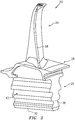
FIG. 1 is a first view of a turbine engine blade. -
FIG. 2 is a second view of the turbine engine blade. -
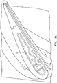
FIG. 3 is a tip view of the turbine engine blade. -
FIG. 3A is an enlarged view of the turbine engine blade tip ofFIG. 3 . -
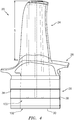
FIG. 4 is an x-ray view of the turbine engine blade. -
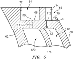
FIG. 5 . is a partial sectional view of the blade ofFIG. 1 , taken along line 5-5 inFIG. 3A . -
FIG. 6 is a cross-sectional view of a shelled pattern including a casting core assembly for casting the blade substrate. -
FIG. 7 is a cross-sectional view of the shell after dewaxing. -
FIG. 8 is a view of the shell after casting the blade substrate. - Like reference numbers and designations in the various drawings indicate like elements.
-
FIG. 1 shows ablade 20 comprising a metallic substrate (e.g., nickel-based superalloy) and optionally one or more coatings (not shown - e.g., ceramic thermal barrier coatings environmental barrier coatings, and the like). The blade and substrate have anairfoil 24, anattachment root 26, and optionally aplatform 28 at a blade-root junction. The attachment root 26 (e.g., firtree or dovetail) has: an inner diameter (ID) end 30 (relative to the centerline of the engine and disk (not shown) in which the blade mounts; anouter diameter end 32 at anunderside 34 of the platform; aforward end 36; and aft end 38 (FIG. 2 ); a first lateral side 40 (FIG. 1 ); and a second lateral side 42 (FIG. 2 ). - The airfoil 24 (
FIG. 3 ) has: an inner diameter (ID)proximal end 50 at the platform outer diameter (OD)gaspath surface 52; atip 54; a leadingedge 56; atrailing edge 58; apressure side 60; and asuction side 62. - The tip 54 (
FIG. 3 ) has at least one of atip pocket 64 and atip shelf 66. Each tip pocket has a base surface 78 and each tip shelf has abase surface 70. Each tip pocket has a sidewall surface 72 (an interior/inner surface) and each tip shelf has a sidewall surface 74 (an interior/inner surface). Where a tip shelf is adjacent a tip pocket, a portion of the tippocket sidewall surface 72 forms an inner surface of a wall structure 73 (FIG. 3 ) separating the tip shelf from the tip pocket and at least a portion of the tipshelf sidewall surface 74 forms an outer surface of thewall structure 73. - The blade and casting further comprise a cooling passageway system 100 (
FIG. 4 ) having one ormore inlets 102 on the attachment root and a plurality of outlets. In typical blades, the outlets may include outlets along the trailing edge, airfoil pressure side, suction side, platform gaspath surface, and tip pocket and/or tip shelf. - The non-limiting example blade has both a
single tip pocket 64 and asingle tip shelf 66, although other variations are possible. Similarly, the example blade hasoutlets 110, 112 (FIG. 3 ) along both the tip pocket and tip shelf, although other variations are possible. The exemplarytip pocket outlets 110 are generally centrally located along thebase surface 68. Theexemplary shelf outlets 112 are along bosses protruding from thebase surface 70 andsidewall surface 74. Theexample tip pocket 64 is fully surrounded by itssidewall surface 72, although tip pockets with outlet gaps in the sidewall are possible. -
FIG. 5 shows theoutlets discharge passageways 111 and 113, respectively, fromfeed passageways passageway system 100. Additional passageways or legs may be distributed streamwise/chordwise within the airfoil. In this particular example, the twopassageways wall section 124. However, alternative embodiments may have the outlet/discharge passageways 111 and 113 fed in common from a single passageway leg or section. - The perimeter of the
tip pocket 64 is the perimeter span SPS of thesidewall surface 72 plus the span across any gap. The perimeter of thetip shelf 66 is similarly the perimeter span Sss of its sidewall surface plus the perimeter span SSG of the gap. The tip pocket gap span, if any, will typically be a small fraction of the tip pocket perimeter (e.g., 5% or less). The tip shelf gap span SSG will typically be a substantial fraction (e.g., at least 40% or at least 60% of the tip shelf perimeter). As is discussed further below, a strongback core is used to cast thetip pocket 64 and/ortip shelf 66 on the one hand and an adjacent portion of the airfoil surface (pressure side 60 and/or suction side 62). Depending on implementation, this adjacent portion may span the leadingedge 56 or trailingedge 58 or may be isolated to one or both of the pressure side and suction side. - As is discussed below, the blade substrate is cast using a strongback core 200 (
FIG. 6 ). In an exemplary process of manufacture, the strongback core 200 (FIG. 6 ) is initially separately formed from a feedcore 202 (e.g., separately molded as two separate ceramic pieces such as silica and/or alumina). The strongback core is then assembled to the feedcore to form acore assembly 206. Alternatively, thecore assembly 206 may also be formed as a unitary piece (e.g. a single molding). Thestrongback core 200 may alternatively be formed by overmolding thefeedcore 202 to create external features of the blade substrate. In areas of the core assembly that are not covered by the pattern material 250 (e.g., protruding from the overmolded pattern material) may become embedded in the shell as discussed below. Areas of the core assembly covered by the pattern material will generally cast corresponding areas of the raw casting. For the strongback core, such areas of the casting include a tip pocket and/or tip shelf and a portion of an airfoil pressure side or suction side. -
FIG. 6 is a partial cross-sectional view of a shelled pattern including acasting core assembly 206, sacrificial pattern material 250 (e.g., wax or leachable polymer), and a shell 252 (e.g., ceramic stucco). Thepattern material 250 is molded over all or a portion of the core assembly and then shelled with ceramic stucco slurry to form theshell 252. Thestrongback core 200 also serves as an anchor between the feedcore 206 and theshell 252. The wax may be removed and the shell fired to harden, leaving a cavity (FIG. 7 ) corresponding to the casting. The substrate alloy is then cast in the shell over the core assembly (FIG. 8 ). Thereafter deshelling (e.g., mechanical breaking) and decoring (e.g., acid and/or alkali leaching and/or thermo-oxidative process) may leave a raw casting. The raw casting may be finish machined, coated and the like. - In one example of assembly of the
core assembly 206, yet separately-formed rods 208 (e.g., molded ceramic such as silica and/or alumina) connect the strongback core to the feedcore. The rods may have respective end portions received in pockets (e.g., circular drilled bores or similar molded pockets) of the feedcore and strongback core. The rods may each have an exposedcentral portion 210 spanning agap 212 between the strongback core and feedcore. Thecentral portions 220 moldrespective outlet passageways 111, 113 with the gap molding a tip end wall forming the base of the tip pocket and/or shelf. Thestrongback core 200 has asection 220 for casting the tip pocket and tip shelf. Thesection 220 has a first protrudingportion 222 for casting the tip pocket and a second protrudingportion 224 for casting the tip shelf. Thefirst portion 222 has anend surface 226 for casting the tippocket base surface 68 and alateral surface 228 for casting the tippocket sidewall surface 72. Similarly, thesecond portion 224 has anend surface 230 for casting the tipshelf base surface 70 and alateral surface 232 for casting the tipshelf sidewall surface 74. - The
strongback core 200 has asecond section 240 extending rootward from the first section and having asurface 242 positioned to cast a portion of at least one of theairfoil pressure side 60 and suction side 62 (in this case pressure side 60). The exemplary airfoil has a swept tip with sweep away from the pressure side.FIG. 5 shows an angle θ between the pressure side and the tip. In an unswept, uncanted, and untapered airfoil, θ would be 90°. Taper would cause only a small deviation. The sweep, however, produces exemplary θ of 100° to 140° or 100° to 130°. - The
surface 242 may extend for a substantial fraction of the gap span SSG (e.g., at least 50% and even more than 100%. This span of thesurface 242 may extend for at least 5% or at least 20% of a local streamwise extent of said at least one of the pressure side and the suction side. Additionally, thesurface 242 may extend spanwise along the airfoil (root-to-tip or radial direction) by a span SR (FIG. 8 ) which is a non-trivial fraction of the airfoil span S ofFIG. 4 . For example, at one or more streamwise locations along thesection 240 and surface 242 SR may extend for at least 2% or at least 5% of the span S at that location. SR may extend up to the full span in embodiments where the strongback core extends all the way to the platform. Alternative upper limits with either of the 2% or 5% lower limits could be 20%, 30%, or 50%. - The use of "first", "second", and the like in the following claims is for differentiation within the claim only and does not necessarily indicate relative or absolute importance or temporal order. Similarly, the identification in a claim of one element as "first" (or the like) does not preclude such "first" element from identifying an element that is referred to as "second" (or the like) in another claim or in the description.
- One or more embodiments have been described. Nevertheless, it will be understood that various modifications may be made. For example, when applied to an existing baseline configuration, details of such baseline may influence details of particular implementations. Accordingly, other embodiments are within the scope of the following claims.
Claims (15)
- A method for casting a blade, the blade comprising:an airfoil having:a proximal end;a tip having at least one of a tip pocket and a tip shelf, each said at least one of a tip pocket and a tip shelf having a base surface and a sidewall surface;a pressure side; anda suction side;an attachment root; anda cooling passageway system having one or more inlets on the attachment root and a plurality of outlets,the method comprising:forming a shell, the forming of the shell including shelling a pattern having at least one ceramic casting core; andcasting in the shell, the shell having a first portion formed by the at least one ceramic casting core and a second potion formed by applied shell material,wherein:for at least a first tip pocket or tip shelf of the least one of a tip pocket and a tip shelf, the at least one ceramic casting core molds the base surface and the sidewall surface and an adjacent portion of at least one of the pressure side and the suction side spanwise inboard of the base surface; andthe casting is optionally an alloy, for example a nickel-based alloy.
- The method of claim 1 wherein:
the adjacent portion is of the pressure side. - The method of claim 1 or 2 wherein:
the adjacent portion extends for at least 5% of a local span of the airfoil. - The method of claim 1, 2 or 3 wherein:
the adjacent portion extends for at least 5% of a local streamwise extent of said at least one of the pressure side and the suction side. - The method of any preceding claim wherein the forming the shell includes forming the pattern by:molding the at least one ceramic casting core; andovermolding a pattern material to the at least one casting core.
- The method of claim 5 further comprising:
forming a core assembly of the at least one ceramic casting core prior to the overmolding. - The method of claim 6 wherein:the at least one ceramic casting core includes a strongback core and a feedcore;the forming of the core assembly includes mounting the strongback core to the feedcore; andthe strongback core molds the base surface and the sidewall surface and the adjacent portion.
- The method of any preceding claim wherein:
the pattern material is a wax. - The method of any preceding claim wherein:
the plurality of outlets include one or more outlets to the at least one of a tip pocket and a tip shelf. - The method of any preceding claim wherein:
the first tip pocket or tip shelf is a first tip shelf. - The method of claim 10 wherein:
the airfoil has a tip sweep providing an angle from the adjacent portion to the first tip shelf base surface of 100° to 130°. - The method of claim 10 or 10 wherein:
the first tip shelf base surface extends for at least 5% of a local streamwise extent of said at least one of the pressure side and the suction side. - The method of claim 10, 10 or 12 wherein:
the first tip shelf base surface extends along a region including the leading edge. - The method of any preceding claim wherein:
the first tip pocket or tip shelf is a first tip pocket. - A casting core or core assembly for casting a blade, the blade comprising:an airfoil having:a proximal end;a tip having at least one of a tip pocket and a tip shelf, each said at least one of a tip pocket and a tip shelf having a base surface and a sidewall surface;a pressure side; anda suction side;an attachment root; anda cooling passageway system having one or more inlets on the attachment root and a plurality of outlets,wherein:for at least a first tip pocket or tip shelf of the least one of a tip pocket and a tip shelf, the casting core or core assembly is shaped and positioned to mold the base surface and the sidewall surface and an adjacent portion of at least one of the pressure side and the suction side spanwise inboard of the base surface; andthe airfoil optionally has a tip sweep providing an angle from the adjacent portion to the first tip shelf base surface of 100° to 140°, for example 100° to 130°.
Applications Claiming Priority (2)
| Application Number | Priority Date | Filing Date | Title |
|---|---|---|---|
| US201962939195P | 2019-11-22 | 2019-11-22 | |
| US16/953,494 US11203058B2 (en) | 2019-11-22 | 2020-11-20 | Turbine blade casting with strongback core |
Publications (2)
| Publication Number | Publication Date |
|---|---|
| EP3825031A1 true EP3825031A1 (en) | 2021-05-26 |
| EP3825031B1 EP3825031B1 (en) | 2022-10-12 |
Family
ID=73544110
Family Applications (1)
| Application Number | Title | Priority Date | Filing Date |
|---|---|---|---|
| EP20209332.4A Active EP3825031B1 (en) | 2019-11-22 | 2020-11-23 | Method and apparatus for casting a turbine blade |
Country Status (2)
| Country | Link |
|---|---|
| US (1) | US11203058B2 (en) |
| EP (1) | EP3825031B1 (en) |
Cited By (1)
| Publication number | Priority date | Publication date | Assignee | Title |
|---|---|---|---|---|
| EP4130429A3 (en) * | 2021-08-06 | 2023-04-12 | Raytheon Technologies Corporation | Airfoil tip arrangement for gas turbine engine |
Families Citing this family (2)
| Publication number | Priority date | Publication date | Assignee | Title |
|---|---|---|---|---|
| US11773726B2 (en) | 2019-10-16 | 2023-10-03 | Rtx Corporation | Angled tip rods |
| EP4166760B1 (en) * | 2021-10-11 | 2025-01-15 | RTX Corporation | Angled tip rods used to cast holes in tips of blade cores of airfoils |
Citations (7)
| Publication number | Priority date | Publication date | Assignee | Title |
|---|---|---|---|---|
| AU2005201580A1 (en) * | 2004-06-14 | 2006-01-05 | United Technologies Corporation | Investment casting |
| US7172012B1 (en) * | 2004-07-14 | 2007-02-06 | United Technologies Corporation | Investment casting |
| US7270170B2 (en) | 2003-12-19 | 2007-09-18 | United Technologies Corporation | Investment casting core methods |
| US20100116452A1 (en) * | 2006-10-18 | 2010-05-13 | United Technologies Corporation | Investment casting cores and methods |
| EP2522444A1 (en) * | 2011-05-10 | 2012-11-14 | Howmet Corporation | Ceramic core with composite insert for casting airfoils |
| US20130266454A1 (en) | 2012-04-05 | 2013-10-10 | United Technologies Corporation | Turbine airfoil tip shelf and squealer pocket cooling |
| US20190106989A1 (en) | 2017-10-09 | 2019-04-11 | United Technologies Corporation | Gas turbine engine airfoil |
Family Cites Families (7)
| Publication number | Priority date | Publication date | Assignee | Title |
|---|---|---|---|---|
| US4078598A (en) | 1976-09-10 | 1978-03-14 | United Technologies Corporation | Strongback and method for positioning same |
| US5599166A (en) | 1994-11-01 | 1997-02-04 | United Technologies Corporation | Core for fabrication of gas turbine engine airfoils |
| US6558119B2 (en) * | 2001-05-29 | 2003-05-06 | General Electric Company | Turbine airfoil with separately formed tip and method for manufacture and repair thereof |
| US6915840B2 (en) | 2002-12-17 | 2005-07-12 | General Electric Company | Methods and apparatus for fabricating turbine engine airfoils |
| US7674093B2 (en) * | 2006-12-19 | 2010-03-09 | General Electric Company | Cluster bridged casting core |
| US10801331B2 (en) * | 2016-06-07 | 2020-10-13 | Raytheon Technologies Corporation | Gas turbine engine rotor including squealer tip pocket |
| US10563521B2 (en) * | 2016-12-05 | 2020-02-18 | United Technologies Corporation | Aft flowing serpentine cavities and cores for airfoils of gas turbine engines |
-
2020
- 2020-11-20 US US16/953,494 patent/US11203058B2/en active Active
- 2020-11-23 EP EP20209332.4A patent/EP3825031B1/en active Active
Patent Citations (8)
| Publication number | Priority date | Publication date | Assignee | Title |
|---|---|---|---|---|
| US7270170B2 (en) | 2003-12-19 | 2007-09-18 | United Technologies Corporation | Investment casting core methods |
| AU2005201580A1 (en) * | 2004-06-14 | 2006-01-05 | United Technologies Corporation | Investment casting |
| US7172012B1 (en) * | 2004-07-14 | 2007-02-06 | United Technologies Corporation | Investment casting |
| US20100116452A1 (en) * | 2006-10-18 | 2010-05-13 | United Technologies Corporation | Investment casting cores and methods |
| US7753104B2 (en) | 2006-10-18 | 2010-07-13 | United Technologies Corporation | Investment casting cores and methods |
| EP2522444A1 (en) * | 2011-05-10 | 2012-11-14 | Howmet Corporation | Ceramic core with composite insert for casting airfoils |
| US20130266454A1 (en) | 2012-04-05 | 2013-10-10 | United Technologies Corporation | Turbine airfoil tip shelf and squealer pocket cooling |
| US20190106989A1 (en) | 2017-10-09 | 2019-04-11 | United Technologies Corporation | Gas turbine engine airfoil |
Cited By (2)
| Publication number | Priority date | Publication date | Assignee | Title |
|---|---|---|---|---|
| EP4130429A3 (en) * | 2021-08-06 | 2023-04-12 | Raytheon Technologies Corporation | Airfoil tip arrangement for gas turbine engine |
| US11913353B2 (en) | 2021-08-06 | 2024-02-27 | Rtx Corporation | Airfoil tip arrangement for gas turbine engine |
Also Published As
| Publication number | Publication date |
|---|---|
| US20210154729A1 (en) | 2021-05-27 |
| US11203058B2 (en) | 2021-12-21 |
| EP3825031B1 (en) | 2022-10-12 |
Similar Documents
| Publication | Publication Date | Title |
|---|---|---|
| JP6315553B2 (en) | Casting cooling structure for turbine airfoil | |
| US10875084B2 (en) | Cluster model and shell for obtaining an accessory for the independent handling of formed parts and associated method | |
| EP1634665B1 (en) | Composite core for use in precision investment casting | |
| US8137068B2 (en) | Castings, casting cores, and methods | |
| EP3825031B1 (en) | Method and apparatus for casting a turbine blade | |
| US7731481B2 (en) | Airfoil cooling with staggered refractory metal core microcircuits | |
| EP3103563B1 (en) | Ceramic core with composite insert for casting airfoils | |
| EP2000232B1 (en) | Cooled wall with thickness control | |
| EP2092996B1 (en) | Method and apparatus for as-cast seal on turbine blades | |
| EP2554294A2 (en) | Hybrid core assembly | |
| EP1923152B1 (en) | Trubine blade casting method | |
| US10155265B2 (en) | Method for positioning core by soluble wax in investment casting | |
| US20050230077A1 (en) | Casting process and cast product | |
| US12365022B1 (en) | Core firing setter | |
| HK1196331B (en) | Cast-in cooling features especially for turbine airfoils | |
| HK1226989B (en) | Ceramic core with composite insert for casting airfoils | |
| HK1226989A1 (en) | Ceramic core with composite insert for casting airfoils |
Legal Events
| Date | Code | Title | Description |
|---|---|---|---|
| PUAI | Public reference made under article 153(3) epc to a published international application that has entered the european phase |
Free format text: ORIGINAL CODE: 0009012 |
|
| STAA | Information on the status of an ep patent application or granted ep patent |
Free format text: STATUS: THE APPLICATION HAS BEEN PUBLISHED |
|
| AK | Designated contracting states |
Kind code of ref document: A1 Designated state(s): AL AT BE BG CH CY CZ DE DK EE ES FI FR GB GR HR HU IE IS IT LI LT LU LV MC MK MT NL NO PL PT RO RS SE SI SK SM TR |
|
| STAA | Information on the status of an ep patent application or granted ep patent |
Free format text: STATUS: REQUEST FOR EXAMINATION WAS MADE |
|
| 17P | Request for examination filed |
Effective date: 20210617 |
|
| RBV | Designated contracting states (corrected) |
Designated state(s): AL AT BE BG CH CY CZ DE DK EE ES FI FR GB GR HR HU IE IS IT LI LT LU LV MC MK MT NL NO PL PT RO RS SE SI SK SM TR |
|
| STAA | Information on the status of an ep patent application or granted ep patent |
Free format text: STATUS: EXAMINATION IS IN PROGRESS |
|
| 17Q | First examination report despatched |
Effective date: 20210817 |
|
| GRAP | Despatch of communication of intention to grant a patent |
Free format text: ORIGINAL CODE: EPIDOSNIGR1 |
|
| STAA | Information on the status of an ep patent application or granted ep patent |
Free format text: STATUS: GRANT OF PATENT IS INTENDED |
|
| INTG | Intention to grant announced |
Effective date: 20220421 |
|
| GRAS | Grant fee paid |
Free format text: ORIGINAL CODE: EPIDOSNIGR3 |
|
| GRAA | (expected) grant |
Free format text: ORIGINAL CODE: 0009210 |
|
| STAA | Information on the status of an ep patent application or granted ep patent |
Free format text: STATUS: THE PATENT HAS BEEN GRANTED |
|
| AK | Designated contracting states |
Kind code of ref document: B1 Designated state(s): AL AT BE BG CH CY CZ DE DK EE ES FI FR GB GR HR HU IE IS IT LI LT LU LV MC MK MT NL NO PL PT RO RS SE SI SK SM TR |
|
| REG | Reference to a national code |
Ref country code: GB Ref legal event code: FG4D |
|
| REG | Reference to a national code |
Ref country code: CH Ref legal event code: EP |
|
| REG | Reference to a national code |
Ref country code: DE Ref legal event code: R096 Ref document number: 602020005589 Country of ref document: DE |
|
| REG | Reference to a national code |
Ref country code: IE Ref legal event code: FG4D |
|
| REG | Reference to a national code |
Ref country code: AT Ref legal event code: REF Ref document number: 1523850 Country of ref document: AT Kind code of ref document: T Effective date: 20221115 |
|
| REG | Reference to a national code |
Ref country code: LT Ref legal event code: MG9D |
|
| REG | Reference to a national code |
Ref country code: NL Ref legal event code: MP Effective date: 20221012 |
|
| REG | Reference to a national code |
Ref country code: AT Ref legal event code: MK05 Ref document number: 1523850 Country of ref document: AT Kind code of ref document: T Effective date: 20221012 |
|
| PG25 | Lapsed in a contracting state [announced via postgrant information from national office to epo] |
Ref country code: NL Free format text: LAPSE BECAUSE OF FAILURE TO SUBMIT A TRANSLATION OF THE DESCRIPTION OR TO PAY THE FEE WITHIN THE PRESCRIBED TIME-LIMIT Effective date: 20221012 |
|
| PG25 | Lapsed in a contracting state [announced via postgrant information from national office to epo] |
Ref country code: SE Free format text: LAPSE BECAUSE OF FAILURE TO SUBMIT A TRANSLATION OF THE DESCRIPTION OR TO PAY THE FEE WITHIN THE PRESCRIBED TIME-LIMIT Effective date: 20221012 Ref country code: PT Free format text: LAPSE BECAUSE OF FAILURE TO SUBMIT A TRANSLATION OF THE DESCRIPTION OR TO PAY THE FEE WITHIN THE PRESCRIBED TIME-LIMIT Effective date: 20230213 Ref country code: NO Free format text: LAPSE BECAUSE OF FAILURE TO SUBMIT A TRANSLATION OF THE DESCRIPTION OR TO PAY THE FEE WITHIN THE PRESCRIBED TIME-LIMIT Effective date: 20230112 Ref country code: LT Free format text: LAPSE BECAUSE OF FAILURE TO SUBMIT A TRANSLATION OF THE DESCRIPTION OR TO PAY THE FEE WITHIN THE PRESCRIBED TIME-LIMIT Effective date: 20221012 Ref country code: FI Free format text: LAPSE BECAUSE OF FAILURE TO SUBMIT A TRANSLATION OF THE DESCRIPTION OR TO PAY THE FEE WITHIN THE PRESCRIBED TIME-LIMIT Effective date: 20221012 Ref country code: ES Free format text: LAPSE BECAUSE OF FAILURE TO SUBMIT A TRANSLATION OF THE DESCRIPTION OR TO PAY THE FEE WITHIN THE PRESCRIBED TIME-LIMIT Effective date: 20221012 Ref country code: AT Free format text: LAPSE BECAUSE OF FAILURE TO SUBMIT A TRANSLATION OF THE DESCRIPTION OR TO PAY THE FEE WITHIN THE PRESCRIBED TIME-LIMIT Effective date: 20221012 |
|
| PG25 | Lapsed in a contracting state [announced via postgrant information from national office to epo] |
Ref country code: RS Free format text: LAPSE BECAUSE OF FAILURE TO SUBMIT A TRANSLATION OF THE DESCRIPTION OR TO PAY THE FEE WITHIN THE PRESCRIBED TIME-LIMIT Effective date: 20221012 Ref country code: PL Free format text: LAPSE BECAUSE OF FAILURE TO SUBMIT A TRANSLATION OF THE DESCRIPTION OR TO PAY THE FEE WITHIN THE PRESCRIBED TIME-LIMIT Effective date: 20221012 Ref country code: LV Free format text: LAPSE BECAUSE OF FAILURE TO SUBMIT A TRANSLATION OF THE DESCRIPTION OR TO PAY THE FEE WITHIN THE PRESCRIBED TIME-LIMIT Effective date: 20221012 Ref country code: IS Free format text: LAPSE BECAUSE OF FAILURE TO SUBMIT A TRANSLATION OF THE DESCRIPTION OR TO PAY THE FEE WITHIN THE PRESCRIBED TIME-LIMIT Effective date: 20230212 Ref country code: HR Free format text: LAPSE BECAUSE OF FAILURE TO SUBMIT A TRANSLATION OF THE DESCRIPTION OR TO PAY THE FEE WITHIN THE PRESCRIBED TIME-LIMIT Effective date: 20221012 Ref country code: GR Free format text: LAPSE BECAUSE OF FAILURE TO SUBMIT A TRANSLATION OF THE DESCRIPTION OR TO PAY THE FEE WITHIN THE PRESCRIBED TIME-LIMIT Effective date: 20230113 |
|
| P01 | Opt-out of the competence of the unified patent court (upc) registered |
Effective date: 20230521 |
|
| REG | Reference to a national code |
Ref country code: DE Ref legal event code: R097 Ref document number: 602020005589 Country of ref document: DE |
|
| REG | Reference to a national code |
Ref country code: BE Ref legal event code: MM Effective date: 20221130 |
|
| PG25 | Lapsed in a contracting state [announced via postgrant information from national office to epo] |
Ref country code: SM Free format text: LAPSE BECAUSE OF FAILURE TO SUBMIT A TRANSLATION OF THE DESCRIPTION OR TO PAY THE FEE WITHIN THE PRESCRIBED TIME-LIMIT Effective date: 20221012 Ref country code: RO Free format text: LAPSE BECAUSE OF FAILURE TO SUBMIT A TRANSLATION OF THE DESCRIPTION OR TO PAY THE FEE WITHIN THE PRESCRIBED TIME-LIMIT Effective date: 20221012 Ref country code: MC Free format text: LAPSE BECAUSE OF FAILURE TO SUBMIT A TRANSLATION OF THE DESCRIPTION OR TO PAY THE FEE WITHIN THE PRESCRIBED TIME-LIMIT Effective date: 20221012 Ref country code: EE Free format text: LAPSE BECAUSE OF FAILURE TO SUBMIT A TRANSLATION OF THE DESCRIPTION OR TO PAY THE FEE WITHIN THE PRESCRIBED TIME-LIMIT Effective date: 20221012 Ref country code: DK Free format text: LAPSE BECAUSE OF FAILURE TO SUBMIT A TRANSLATION OF THE DESCRIPTION OR TO PAY THE FEE WITHIN THE PRESCRIBED TIME-LIMIT Effective date: 20221012 Ref country code: CZ Free format text: LAPSE BECAUSE OF FAILURE TO SUBMIT A TRANSLATION OF THE DESCRIPTION OR TO PAY THE FEE WITHIN THE PRESCRIBED TIME-LIMIT Effective date: 20221012 |
|
| PLBE | No opposition filed within time limit |
Free format text: ORIGINAL CODE: 0009261 |
|
| STAA | Information on the status of an ep patent application or granted ep patent |
Free format text: STATUS: NO OPPOSITION FILED WITHIN TIME LIMIT |
|
| PG25 | Lapsed in a contracting state [announced via postgrant information from national office to epo] |
Ref country code: SK Free format text: LAPSE BECAUSE OF FAILURE TO SUBMIT A TRANSLATION OF THE DESCRIPTION OR TO PAY THE FEE WITHIN THE PRESCRIBED TIME-LIMIT Effective date: 20221012 Ref country code: LU Free format text: LAPSE BECAUSE OF NON-PAYMENT OF DUE FEES Effective date: 20221123 Ref country code: AL Free format text: LAPSE BECAUSE OF FAILURE TO SUBMIT A TRANSLATION OF THE DESCRIPTION OR TO PAY THE FEE WITHIN THE PRESCRIBED TIME-LIMIT Effective date: 20221012 |
|
| 26N | No opposition filed |
Effective date: 20230713 |
|
| PG25 | Lapsed in a contracting state [announced via postgrant information from national office to epo] |
Ref country code: IE Free format text: LAPSE BECAUSE OF NON-PAYMENT OF DUE FEES Effective date: 20221123 |
|
| PG25 | Lapsed in a contracting state [announced via postgrant information from national office to epo] |
Ref country code: SI Free format text: LAPSE BECAUSE OF FAILURE TO SUBMIT A TRANSLATION OF THE DESCRIPTION OR TO PAY THE FEE WITHIN THE PRESCRIBED TIME-LIMIT Effective date: 20221012 Ref country code: BE Free format text: LAPSE BECAUSE OF NON-PAYMENT OF DUE FEES Effective date: 20221130 |
|
| PG25 | Lapsed in a contracting state [announced via postgrant information from national office to epo] |
Ref country code: CY Free format text: LAPSE BECAUSE OF FAILURE TO SUBMIT A TRANSLATION OF THE DESCRIPTION OR TO PAY THE FEE WITHIN THE PRESCRIBED TIME-LIMIT Effective date: 20221012 |
|
| PG25 | Lapsed in a contracting state [announced via postgrant information from national office to epo] |
Ref country code: MK Free format text: LAPSE BECAUSE OF FAILURE TO SUBMIT A TRANSLATION OF THE DESCRIPTION OR TO PAY THE FEE WITHIN THE PRESCRIBED TIME-LIMIT Effective date: 20221012 Ref country code: IT Free format text: LAPSE BECAUSE OF FAILURE TO SUBMIT A TRANSLATION OF THE DESCRIPTION OR TO PAY THE FEE WITHIN THE PRESCRIBED TIME-LIMIT Effective date: 20221012 |
|
| REG | Reference to a national code |
Ref country code: CH Ref legal event code: PL |
|
| PG25 | Lapsed in a contracting state [announced via postgrant information from national office to epo] |
Ref country code: CH Free format text: LAPSE BECAUSE OF NON-PAYMENT OF DUE FEES Effective date: 20231130 |
|
| PG25 | Lapsed in a contracting state [announced via postgrant information from national office to epo] |
Ref country code: CH Free format text: LAPSE BECAUSE OF NON-PAYMENT OF DUE FEES Effective date: 20231130 Ref country code: BG Free format text: LAPSE BECAUSE OF FAILURE TO SUBMIT A TRANSLATION OF THE DESCRIPTION OR TO PAY THE FEE WITHIN THE PRESCRIBED TIME-LIMIT Effective date: 20221012 |
|
| PG25 | Lapsed in a contracting state [announced via postgrant information from national office to epo] |
Ref country code: MT Free format text: LAPSE BECAUSE OF FAILURE TO SUBMIT A TRANSLATION OF THE DESCRIPTION OR TO PAY THE FEE WITHIN THE PRESCRIBED TIME-LIMIT Effective date: 20221012 |
|
| PG25 | Lapsed in a contracting state [announced via postgrant information from national office to epo] |
Ref country code: HU Free format text: LAPSE BECAUSE OF FAILURE TO SUBMIT A TRANSLATION OF THE DESCRIPTION OR TO PAY THE FEE WITHIN THE PRESCRIBED TIME-LIMIT; INVALID AB INITIO Effective date: 20201123 |
|
| REG | Reference to a national code |
Ref country code: DE Ref legal event code: R081 Ref document number: 602020005589 Country of ref document: DE Owner name: RTX CORPORATION (N.D.GES.D. STAATES DELAWARE),, US Free format text: FORMER OWNER: RAYTHEON TECHNOLOGIES CORPORATION, FARMINGTON, CT, US |
|
| PG25 | Lapsed in a contracting state [announced via postgrant information from national office to epo] |
Ref country code: TR Free format text: LAPSE BECAUSE OF FAILURE TO SUBMIT A TRANSLATION OF THE DESCRIPTION OR TO PAY THE FEE WITHIN THE PRESCRIBED TIME-LIMIT Effective date: 20221012 |
|
| PGFP | Annual fee paid to national office [announced via postgrant information from national office to epo] |
Ref country code: DE Payment date: 20251022 Year of fee payment: 6 |
|
| PGFP | Annual fee paid to national office [announced via postgrant information from national office to epo] |
Ref country code: GB Payment date: 20251023 Year of fee payment: 6 |
|
| PGFP | Annual fee paid to national office [announced via postgrant information from national office to epo] |
Ref country code: FR Payment date: 20251022 Year of fee payment: 6 |