EP3824926A1 - Receptacle for pharmaceutical packaging having a graduated lubricant layer - Google Patents
Receptacle for pharmaceutical packaging having a graduated lubricant layer Download PDFInfo
- Publication number
- EP3824926A1 EP3824926A1 EP19210762.1A EP19210762A EP3824926A1 EP 3824926 A1 EP3824926 A1 EP 3824926A1 EP 19210762 A EP19210762 A EP 19210762A EP 3824926 A1 EP3824926 A1 EP 3824926A1
- Authority
- EP
- European Patent Office
- Prior art keywords
- receptacle
- charge
- axial position
- layer
- interior
- Prior art date
- Legal status (The legal status is an assumption and is not a legal conclusion. Google has not performed a legal analysis and makes no representation as to the accuracy of the status listed.)
- Granted
Links
Images




Classifications
-
- A—HUMAN NECESSITIES
- A61—MEDICAL OR VETERINARY SCIENCE; HYGIENE
- A61M—DEVICES FOR INTRODUCING MEDIA INTO, OR ONTO, THE BODY; DEVICES FOR TRANSDUCING BODY MEDIA OR FOR TAKING MEDIA FROM THE BODY; DEVICES FOR PRODUCING OR ENDING SLEEP OR STUPOR
- A61M5/00—Devices for bringing media into the body in a subcutaneous, intra-vascular or intramuscular way; Accessories therefor, e.g. filling or cleaning devices, arm-rests
- A61M5/178—Syringes
- A61M5/31—Details
- A61M5/3129—Syringe barrels
-
- A—HUMAN NECESSITIES
- A61—MEDICAL OR VETERINARY SCIENCE; HYGIENE
- A61M—DEVICES FOR INTRODUCING MEDIA INTO, OR ONTO, THE BODY; DEVICES FOR TRANSDUCING BODY MEDIA OR FOR TAKING MEDIA FROM THE BODY; DEVICES FOR PRODUCING OR ENDING SLEEP OR STUPOR
- A61M5/00—Devices for bringing media into the body in a subcutaneous, intra-vascular or intramuscular way; Accessories therefor, e.g. filling or cleaning devices, arm-rests
- A61M5/178—Syringes
- A61M5/31—Details
- A61M5/3129—Syringe barrels
- A61M2005/3131—Syringe barrels specially adapted for improving sealing or sliding
Definitions
- the invention generally relates to a receptacle for pharmaceutical packaging having a graduated layer of lubricant.
- the invention relates to a receptacle; a kit comprising a receptacle and a charge; an assembly comprising a receptacle, a charge and a liquid pharmaceutical composition; a process for the preparation of a receptacle and a use of a lubricant layer of graduated thickness.
- Pharmaceutical material can be provided in a number of forms and contained in a variety of different containers.
- some common examples are ampules, vials, cartridges and syringes.
- One widely used format employs a sliding plunger within a container for ejecting a liquid out of an aperture.
- One approach is to provide a lubricating layer on the inside of the container to facilitate sliding movement of the plunger.
- U.S. Patent Application Document No. 4,767,414 A describes plasma activation of an inner surface prior to application of a layer of silicone lubricant.
- EP 0920879 B1 describes a recipe for a silicone-based mixture comprising reactive components and unreactive components.
- It is an object of the invention to provide an improved assembly comprising a receptacle, a charge and a liquid pharmaceutical composition, in particular for multi-dose delivery.
- the following combinations of the receptacle criteria i. to iv. are fulfilled: i., ii., iii., iv., i.+ii., i.+iii., i.+iv., ii.+iii., ii.+iv., iii.+iv., i.+iii.+iv., i.+iiii.+iv., i.+iiii.+iv., ii.+iii.+iv., ii.+iii.+iv & i.+ii.+iii.+iv..
- the axis of the receptacle is used to determine axial position.
- the side wall is a perimeter having a thickness lying in a cross-sectional plane perpendicular to the axis, likewise for the lubricant layer.
- Internal diameter, thickness of the lubricant layer, thickness of the side wall and surface roughness at a given point along the axis are preferably mean values determined around a perimeter.
- a mean around a perimeter is an angular mean.
- An angular mean is preferably determined by measuring at 8 points around the perimeter, the 8 points being separated by equal angles.
- Monotonicity for a parameter Y over the portion X is preferably determined as follows:
- a preferred receptacle is adapted and arranged to contain a pharmaceutical liquid.
- Some preferred receptacles are syringes, syringe barrels, cartridges, dead-end containers and vials.
- a preferred receptacle has one or more apertures.
- An aperture is preferably located at an end of the receptacle.
- the receptacle has one aperture.
- the receptacle has two apertures.
- the receptacle preferably has two ends, a first end and a second end.
- a preferred receptacle has a first aperture at a first end.
- One type of preferred receptacle has a second aperture at a second end.
- Another type of preferred receptacle has a dead end at a second end.
- the receptacle has an elongate barrel section.
- the elongate barrel section denominates a section of the receptacle.
- the receptacle may have further sections outside of the elongate barrel section.
- Another term for an elongate barrel section is a tube section.
- a preferred elongate barrel section is tubular.
- elongate barrel section and the axis are described herein in mathematical terms, for example as axes of symmetry, rotation or revolution, surfaces and solids of revolution and shapes such as cylinders and truncated cones. These embodiments are to be understood as allowing some variation from these precise mathematical concepts. Suitable variations from the mathematic concepts are those which do not inhibit the receptacle from functioning as a plunger system in cooperation with a charge.
- the elongate barrel section has an axis.
- the axis may be an axis of rotation for the elongate barrel section.
- the axis may be an axis of revolution for the elongate barrel section.
- the side wall may be a solid of revolution about the axis.
- the inner surface may be a surface of revolution about the axis.
- the layer may be a solid of revolution about the axis.
- the axis defines an axial position p.
- the axial position p is an axial position along the axis.
- the symbol p denotes an axial position in general terms and specific axial positions are denoted by the letter p with a subscript.
- An axial position p along the axis is used as a parameter to describe the locations of points or cross-sections along the elongate barrel section, for example on the side wall.
- the axial position of a point not on the axis is found by projecting the point onto the axis by a displacement vector perpendicular to the axis.
- a cross section is a plane perpendicular to the axis. The axial position of a cross section is found at the point where the cross section meets the axis.
- the elongate barrel section extends from an axial position p A to an axial position p B .
- the elongate barrel section is contained by a cross section at p A and a cross section at p B .
- the receptacle has a first end and a second end, the receptacle is adapted and arranged for ejecting a liquid pharmaceutical composition from the second end and p B is closer to the second end than is p A .
- the receptacle has a first end and a second end, the first end is a dead end with no aperture, the second end is an open end with an aperture and p B is closer to the second end than is p A .
- the receptacle has a side wall extending over the elongate barrel section.
- the side wall has an inner surface.
- the inner surface borders an interior.
- Preferred shapes for the side wall are a hollow cylinder, a hollow prism and a hollow truncated cone.
- a preferred hollow truncated cone has a diameter which decreases from p A to p B .
- Preferred shapes for the interior are a cylinder, a prism and a truncated cone.
- a preferred truncated cone has a diameter which decreases from p A to p B .
- the inner surface is preferably smooth, but may have some roughness.
- the thickness of the side wall is preferably measured as a difference in radial distance from the axis of the inner surface and an outer surface of the side wall.
- the thickness of the side wall is preferably measured as a difference in radial distance from the axis of an inner surface of the layer and the inner surface of the side wall.
- Preferred materials for the side wall are polymers and glasses.
- the side wall comprises a polymer, preferably is made out of a polymer.
- the polymer is preferably one or both selected from the group consisting of: one or more cyclic olefin copolymers and one or more cyclic olefin polymers.
- the polymer is preferably at least 30 wt. % of the side wall, more preferably at least 50 wt. %, more preferably at least 80 wt. %, most preferably about 100 wt. %.
- the side wall comprises a glass, preferably is made of a glass.
- a preferred glass in this context comprises one or more selected from the group consisting of: silicon, boron and aluminium.
- One preferred glass comprises boron and silicon.
- One preferred glass is a borosilicate glass.
- One preferred glass comprises aluminium and silicon.
- One preferred glass is an aluminosilicate glass.
- the glass is preferably at least 30 wt. % of the side wall, more preferably at least 50 wt. %, more preferably at least 80 wt. %, most preferably about 100 wt. %.
- the layer of lubricant is located on the inner surface of the side wall.
- the lubricant layer may extend over the entire elongate barrel section or just a part of it.
- the lubricant layer extends over the entire portion X.
- a preferred lubricant is a silicone-based lubricant.
- a preferred lubricant comprises one or more polysiloxanes.
- a preferred lubricant comprises one or more silicone oils, preferably a total content of silicone oils in the range from 10 to 50 wt. %, more preferably in the range from 20 to 40 wt. %, most preferably in the range from 25 to 35 wt. %, based on the total weight of the lubricant.
- a preferred silicone oil is a poly dimethyl silicone.
- a preferred lubricant comprises a crosslinked polysiloxane matrix, preferably a total content of crosslinked polysiloxane matrix in the range from 50 to 90 wt. %, more preferably in the range from 60 to 80 wt. %, most preferably in the range from 65 to 75 wt. %, based on the total weight of the lubricant.
- a preferred lubricant may be prepared from a mixture comprising one or more, preferably all, of the following:
- a preferred reactive polysiloxane is adapted and arranged to undergo a cross-linking reaction to obtain a cross-linked network.
- the cross-linking may be catalysed by the catalyst.
- a preferred unreactive polysiloxane does not undergo a cross-linking reaction.
- a preferred unreactive polysiloxane comprises one or more alkyl groups.
- a further preferred unreactive polysiloxane is fully substituted with alkyl groups.
- a preferred catalyst catalyses a reaction to cross-link polysiloxanes.
- a preferred diluent solves one or more of the other constituents of the mixture.
- a preferred diluent is silicon based.
- a preferred diluent is a short chain polysiloxane, preferably having 6 repeat units or less.
- a preferred diluent is hexamethyl disiloxane.
- a preferred lubricant contains not more than 10 wt. % water, based on the total weight of the lubricant, preferably not more than 5 wt. %, more preferably not more than 1 wt. %.
- the lubricant layer has a thickness profile from p 1 to p 2 .
- the thickness of the layer at p 2 is greater than the thickness of the layer at p 2 , preferably by at least 100 nm, more preferably by at least 500 nm, more preferably still by at least 1 ⁇ m.
- the thickness of the lubricant layer increases monotonically over the portion from p 1 to p 2 .
- the thickness of the lubricant layer satisfies the following:
- the layer extends over at least 70%, more preferably at least 80%, more preferably at least 90%, most preferably at least 94%, most preferably at least 98%, most preferably about 100% of the length L B of the elongate barrel section.
- the lubricant extends over 20 to 60 % of the length L B elongate barrel section.
- the lubricant layer has a minimum thickness t min determined between p 1 and p 2 inclusive of at least 60 nm, preferably at least 90 nm, more preferably at least 100 nm, most preferably at least 110 nm.
- the layer has a minimum thickness t min determined between pi and p 2 inclusive which is greater than the mean roughness of the inner surface of the side wall between p 1 and p 2 , preferably at least 20 nm greater, more preferably at least 40 nm, more preferably at least 60 nm greater.
- the receptacle is for pharmaceutical packaging.
- a preferred receptacle is adapted and arranged to contain a liquid.
- a liquid pharmaceutical composition preferably comprises an active compound.
- a liquid pharmaceutical composition is a fluid.
- a preferred amount of liquid pharmaceutical composition is in the range from 0.1 to 150 ml, preferably in the range from 0.5 to 70 ml, more preferably in the range from 0.8 to 40 ml, most preferably in the range from 1 to 10 ml, most preferably in the range from 2 to 5 ml.
- the receptacle is adapted and arranged to accommodate a charge.
- a preferred charge is adapted and arranged to be accommodated in the receptacle.
- the receptacle are preferably complementary such that the charge can be introduced into the interior of the receptacle and such that the charge can move within the interior in a direction parallel to the axis.
- a preferred charge is made of an elastic material or comprises a part made of an elastic material.
- the charge is preferably adapted and arranged to seal a cross-section of the interior.
- the charge is preferably adapted and arranged to move inside the receptacle, preferably along the axis defined by the elongate extension of the receptacle. When inside the receptacle, movement of the charge is preferably resisted by a frictional force between the charge and an inside surface of the receptacle.
- the charge may be attached to an elongate rod adapted and arranged to push or pull the charge in a direction parallel to the axis.
- a preferred charge is a plunger.
- the charge When in position in the receptacle, the charge makes contact with the layer or the inner surface or both.
- the front end of the charge is the point of forwardmost contact, in a direction from p A to p B , of the charge with the layer or the inner surface.
- the back end of the charge is the point of backmost contact, in a direction from p A to p B , of the charge with the layer or the inner surface.
- the charge axial position is the axial position of the front end of the charge.
- the distance between the front end and the back end of the charge is the charge length Lc.
- a contribution to at least partially solving one or more of the above-mentioned objects is made by a kit comprising a receptacle according to this disclosure and a charge according to this disclosure.
- the charge and the receptacle are preferably complementary such that the charge can be accommodated in the receptacle and can move within the interior in a direction parallel to the axis.
- the movement of the charge within the receptacle is accompanied by a frictional force between the charge and the inner surface of the side wall and or the layer.
- the frictional force comprises both a stiction which resists the setting in motion of the charge relative to the receptacle and a dynamic friction which acts whilst the charge is in movement.
- the stiction is dependent on the charge axial position.
- the stiction at a given charge axial position p is preferably determined by starting the charge at charge axial position p 1 + L C , moving the charge from p 1 + L C at a constant speed of 100 mm/minute, letting the charge come to rest at charge axial position p, for example equidistant between p 1 + L C and p 2 , and finally bringing the charge into motion in a direction to towards charge axial position p 2 .
- the stiction at charge axial position p is the force required to bring the charge into motion in the final step.
- the stiction is preferably lower towards the second end of the receptacle than towards the first end of the receptacle, preferably satisfying the criterion of embodiment
- the stiction at charge axial position p 2 is preferably less than the stiction at charge axial position p 1 + L C .
- the stiction s preferably reduces monotonically from p 1 + L C to p 2 .
- the stiction is preferably relatively uniform from p 1 + L C to p 2 , preferably satisfying the criterion of embodiment
- a contribution to at least partially solving at least one of the above-mentioned objects is made by an assembly comprising a receptacle, a charge and a liquid pharmaceutical composition.
- the charge is positioned inside the receptacle to seal a cross-section of the interior.
- the liquid pharmaceutical composition is present in the interior between the cross-section sealed by the charge and an aperture of the receptacle.
- the liquid pharmaceutical composition fills at least 50 vol. % of the interior, preferably at least 70 vol. %, more preferably at least 80 vol. %.
- the liquid pharmaceutical composition fills less than 50 vol. % of the interior, or less than 30 vol. %, or less than 20 vol. %.
- the assembly is preferably adapted and arranged such that the liquid pharmaceutical composition can be ejected from the interior by moving the charge in a direction parallel to the axis towards the second end.
- a preferred assembly functions as a plunger system in which the liquid pharmaceutical composition can be ejected from the receptacle through movement of the charge.
- a preferred receptacle has an attachment means, preferably at an end.
- a preferred attachment means is adapted and arranged for attaching a needle or tube.
- a needle or tube may be attached to the receptacle in the assembly.
- Preferred receptacles be they receptacles as such or as part of a kit or an assembly, have a Luer fitting.
- a preferred Luer fitting is compatible with ISO 80369.
- Preferred Luer fittings are Luer lock fittings and slip tip fittings, preferably Luer lock fittings.
- the receptacle has a Luer lock fitting.
- the receptacle has a slip tip fitting.
- a preferred Luer fitting is a male Luer fitting.
- Preferred Luer lock fittings are one-piece Luer lock fittings and two-piece Luer lock fittings.
- the receptacle has a one-piece Luer lock fitting.
- the receptacle has a tow-piece Luer lock fitting.
- a receptacle according to this disclosure may be prepared by providing a receptacle without a layer lubricant and applying a layer of lubricant to the inner surface of the side wall of the receptacle.
- Preferred methods for applying the layer are spreading and wiping, preferably with a suitable tool.
- An assembly may be prepared by the following steps:
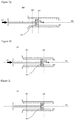
- Figure 1 shows a cross-sectional view of a receptacle 100 with a lubricant layer 106 on an inner surface 118 of a side wall 107.
- the receptacle 100 has a first end 119 and a second end 120. At the first end 119 is a first aperture 102 and an outwardly protruding flange 105. At the second end 120 is a second aperture 103 and an attachment means 104, in this case a screw thread, for attaching a needle fitting.
- the receptacle 100 has an elongate barrel section 501 extending from an axial position p A to an axial position p B .
- the elongate barrel section 501 has a hollow truncated conical shape with a greater diameter at p A than at p B .
- the length of the elongate barrel section 501 is L B .
- the axis 101 is in the direction of elongate extension of the receptacle 100 and is the axis of rotation of the elongate barrel section 501.
- the side wall 107 has an inner surface 118, on which is present a layer 106 of lubricant. The layer 106 extends over some, but not all of the side wall 107, not reaching the ends p A and p B .
- a portion X of the elongate barrel section 501 runs between axial positions p 1 to p 2 .
- the portion X is an abstract portion selected according to the criteria presented in the embodiments and claims.
- the end points p 1 and p 2 both lie within the bounds of the layer 106.
- the purpose of selecting the abstract portion X of the elongate barrel section 501 is to ensure that irregularities at the ends of the elongate barrel section 501 are avoided, in particular since the layer 106 may not extend all the way to the ends p A and p B , as in this example.
- Axial positions along the receptacle 100 are measured along the axis 101. Axial positions may be given with reference to p 1 as a fiduciary zero point.
- the thicknesses t 1 at axial position p 1 and t 2 at axial position p 2 are shown. According to this disclosure, t 2 is greater than t 1 . In the case shown, t 1 and t 2 are rather similar, but the difference could be much more marked.
- Figures 2a to 2m show a multi-push movement of a charge 203 in a receptacle 100.
- the series of figures demonstrates how the charge 203 may be pushed along the axis 101 of the receptacle 100 in multiple pushes in between which the charge 203 comes to rest at least once on its path along the axis 101. In the process shown, the charge 203 comes to rest at two intermediate axial positions along its path.
- the process presented can also be used to construct a profile of dynamic friction and stiction for the receptacle/charge combination as a function of distance along the axis 101.
- FIG. 2a shows a receptacle 100 ready for multi-push movement of a charge 203.
- the receptacle 100 is in this case a syringe barrel, having a major hollow truncated conical section (The angle of inclination of the truncated cone is very slight and the elongate barrel section has been represented as a cylinder for simplicity of view).
- An axis 101 is in the direction of the elongate extension of the receptacle 100.
- the axis 101 is the axis of rotation of the conical/cylindrical section.
- At a first end 119 of the receptacle 100 is a first aperture 102 and an outwardly protruding flange 105.
- a second aperture 103 which exhibits a narrowing and is adapted and arranged to attach a needle.
- the first aperture 102 has a greater diameter area than the second aperture 103.
- the receptacle 100 has a cylindrical side wall 107 and an interior 121.
- a layer 106 of lubricant is present on the inner surface 118 of the side wall 107.
- the lubricant layer 106 is present along the majority of the side wall 107. In this case, the portion X covers most of the lubricant layer 107, with p 1 and p 2 slightly removed from the ends of the layer 107 in order to avoid end effects.
- the layer 106 of lubricant has a thickness 210, shown at a general axial position along the axis 101. For ease of depiction, the layer 106 is shown roughly uniform, but the preferred thickness profile is described elsewhere in this document.
- a charge 203 Present in the interior 121, towards the first end 119 of the receptacle 100, is a charge 203.
- the charge 203 is a stopper of elastomer material having an attached elongate rod 202.
- the charge 203 has ribbed side walls.
- the elongate rod 202 can be used to push the charge 203 along the axis 101 in the manner of a plunger.
- the axial position of the charge 203 is defined as the axial position of the front end of the charge 203.
- the charge 203 is shown in an initial axial position 201 in which the back end of the charge 203 is at p 1 . In the initial state presented, no force is applied to the charge via the elongate rod 202
- Figure 2b shows the receptacle 100 of figure 1 , in which a pushing force 207 is applied to the elongate rod 202 in a direction along the axis 101.
- the force 207 is transferred to the charge 203.
- the force 207 is inferior to the stiction at the axial position 201 and the charge 203 is at rest, with the pushing force 207 cancelled out by the static frictional force between the charge 203 and the side walls 207 / lubricant layer 106.
- the stiction at the axial position 201 is determined as the force 207 at which the charge 203 starts to move along the axis 101.
- Figure 2c shows the receptacle 100 immediately after the pushing force 207 in figure 2b exceeds the stiction at axial position 201 to put the charge 203 into motion.
- the charge 203 is depicted at the axial position 201, but in motion 208 along the axis 101.
- the pushing force 207 is equal to the dynamic friction at axial position 201 and the charge 203 is in a state of constant velocity along the axis 101.
- the charge 203 is moved between rest axial positions at a constant speed of 100 mm/min.
- Figure 2d shows the receptacle 100 subsequent to that of figure 2c , in which the charge 203 has travelled a distance from 201 to an intermediate axial position 204 along the axis 101.
- the charge 203 is still in motion 208 with constant velocity of 100 mm/min with the pushing force 207.
- Figure 2e shows the receptacle 100 in which the pushing force 207 has been released at axial position 204.
- the charge is at rest at the axial position 204.
- Figures 2e to 2i are analogous to figures 2a to 2e .
- the charge 203 is initially at rest at axial position 204 ( figure 2e ) and is set in motion 208 by a force 207 exceeding the stiction at axial position 204 ( figure 2f ).
- the charge 203 starts moving 208 along the axis 101 at axial position 204 ( figure 2g ) and arrives in motion 208 at a further intermediate axial position 205 ( figure 2h ), where the pushing force 207 is released and the charge 203 comes to a stop ( figure 2i ).
- the speed between rest axial positions is maintained constant at 100 mm/min.
- Figures 2i to 2m are analogous to figures 2a to 2e and figures 2e to 2i respectively.
- the charge 203 is initially at rest at axial position 205 ( figure 2i ) and is set in motion 208 by a force 207 exceeding the stiction at axial position 205 ( figure 2j ).
- the charge 203 starts moving 208 along the axis 101 at axial position 205 ( figure 2k ) and arrives in motion 208 at the final axial position 206 ( figure 2l ), where the pushing force 207 is released and the charge 203 comes to a stop ( figure 2m ).
- the axial position 206 is where the front end of the charge has arrived at axial position p 2 , close to the end of the lubricated layer 106 and is in its final rest axial position.
- the speed between rest axial positions is maintained constant at 100 mm/min.
- Figure 3 shows a cross-sectional view through the receptacle 100 at an axial position p along the axis 101.
- the side wall 107 and the lubricant layer 106 are shown as concentric circular bands.
- the thickness 301 of the side wall 107 and the thickness 302 of the lubricant layer 106 are each shown at 8 equidistant points around the circle.
- a thickness of a side wall 107 or a layer 106 of lubricant at an axial position p is a mean of the thickness around the circle. This is measured as the mean of a number of equally spaced sample points around the circle, in this case 8.
- Figures 4a to 4e show the process of preparing an assembly and ejecting a pharmaceutical product 401.
- Figure 4a shows a receptacle 100, ready for forming an assembly.
- the receptacle 100 has an axis of rotation 101, a side wall 107 and an interior 121.
- a layer 106 of lubricant is present on the inside of the receptacle 100.
- the receptacle 100 has a first aperture 102 and a second aperture 103.
- Figure 4b shows the receptacle 100 of figure 4a with a charge 203 located in the interior 121.
- the front end of the charge 203 is at an axial position 201 along the axis, close to the first aperture 102.
- the back end of the charge 203 is at p 1 , close to the start of the lubricant layer 107.
- Figure 4c shows the receptacle 100 of figure 4b after having been filled with a liquid pharmaceutical composition 401.
- the liquid pharmaceutical composition 401 is located in the interior 121 between the front end of the charge 201 and the second aperture 103.
- the receptacle 100, the charge 203 and the liquid pharmaceutical composition 401 constitute and assembly.
- Figure 4d shows the assembly of figure 4c in which a pushing force 207 is applied to push the charge 203 along the axis 101 in a direction from the first aperture 102 towards the second aperture 103.
- the motion 208 of the charge 203 forces the liquid pharmaceutical composition 401 to be ejected 402 from the receptacle 100.
- Figure 4e shows the assembly of figure 4d once the charge 203 has travelled along the axis 101 in a direction from the first aperture 102 towards the second aperture 103 to arrive at axial position p 2 near the end of the layer 106 of lubricant.
- the liquid pharmaceutical composition 401 has been ejected via the second aperture 103 and only a small quantity remains in the tip of the receptacle at the second aperture 103.
- Figure 5 shows a thickness profile 200 of the layer 106 of lubricant.
- the thickness t increases from a value of t 1 122 at an axial position p 1 115 to a value of t 2 123 at an axial position p 2 117.
- the gradient of the thickness against axial position is not negative anywhere along the extent from p 1 115 to p 2 117.
- the profile is monotonic.
- Figure 6 shows determination of a monotonically increasing thickness profile.
- the stretch from p 1 to p 2 has been split into 10 sections M 1 to Mio of equal size.
- the mean thickness over the sections M 1 to Mio is T 1 to T 10 respectively.
- the longer-range monotonicity of the thickness profile is evident from the strictly ascending ordering from T 1 to T 10 , without descending, as can be seen on the t axis.
- Figure 7 shows a stiction profile for the kit of example 1.
- the stiction profile is determined using the procedure as presented in the figures 2a to 2m , except with 3 intermediate rest points at 15, 30 and 45 mm from the start point 201. The test was performed 10 times with fresh kits (all 10 lines shown in the figure). In each run, a smooth stiction profile was observed, mildly decreasing from around 4.8-6.2 N at 201 to around 2.8-3.8 N at 45 mm from c ⁇ .
- the gently and monotonically decreasing stiction profile is well suited to be employed in a multi-dose syringe. As can be seen, the transition between stiction and dynamic friction is smooth, allowing better control of multi-dose ejection.
- the thickness of the layer is determined by optical interference measurements using the RapID Explorer available from rap.ID Particle Systems GmbH. Measurements are taken from outside the receptacle through the side wall. The device is operated with the proprietary software and in accordance with the 2014 proprietary instruction manual.
- Surface roughness of the inner surface of the side wall is measured using a white-light interference microscope.
- An area of the sample of 2 ⁇ m by 2 ⁇ m is scanned in tapping mode, scanning the area with 256 lines per picture and 256 dots per line.
- the scan rate is 0.7 Hz.
- the cantilever has a tip with a tip radius of ⁇ 10nm.
- the sample's topography is measured by evaluating the change of the amplitude of the oscillating cantilever when scanning the surface.
- the raw data is levelled by a line fit, using a 3 rd order polynomial fit.
- a receptacle was provided according to figure 1 .
- the receptacles was a 1 ml lg TopPac available from Schott AG Germany.
- the inner surface of the side walls of the elongate barrel section was coated with a silicone coating, extending up to 1 mm from each of the two ends of the elongate barrel section.
- the thickness profile of the applied layer was according to table 1.
- the receptacle was tested by introducing a charge made of elastomer with an attached elongate rod according to figure 2a , charge FM 257/2 available from Dedecke GmbH, Germany.
- the process similar to that displayed in figures 2a to 2m starting at 5 mm along the barrel and with 3 intermediate stop points, at 15, 30 and 45 mm along the barrel, was performed to determine the stiction along the barrel.
- the root mean square of the roughness of the inner surface of the side wall over the section from p 1 to p 2 was determined to be 62 nm.
- Table 1 Example Distance along barrel [mm] 0 10 20 30 40 50 60 Thickness t [nm] 1 71 279 722 1014 1304 1708 1863 2 74 511 1423 1982 2356 2870 3987 3 2102 1677 1298 1012 697 311 69 4 956 944 963 961 948 951 960
- Table 2 Example Distance along barrel [mm] 5 15 30 45 Stiction [N] 1 6.2 5.0 4.3 3.7 2 5.7 4.6 3.8 2.8 3 5.8 6.4 7.1 7.8 4 6.0 6.1 6.1 6.2
Landscapes
- Health & Medical Sciences (AREA)
- Vascular Medicine (AREA)
- Engineering & Computer Science (AREA)
- Anesthesiology (AREA)
- Biomedical Technology (AREA)
- Heart & Thoracic Surgery (AREA)
- Hematology (AREA)
- Life Sciences & Earth Sciences (AREA)
- Animal Behavior & Ethology (AREA)
- General Health & Medical Sciences (AREA)
- Public Health (AREA)
- Veterinary Medicine (AREA)
- Infusion, Injection, And Reservoir Apparatuses (AREA)
Abstract
Description
- The invention generally relates to a receptacle for pharmaceutical packaging having a graduated layer of lubricant. In particular, the invention relates to a receptacle; a kit comprising a receptacle and a charge; an assembly comprising a receptacle, a charge and a liquid pharmaceutical composition; a process for the preparation of a receptacle and a use of a lubricant layer of graduated thickness.
- Pharmaceutical material can be provided in a number of forms and contained in a variety of different containers. In the case of a liquid pharmaceutical material, some common examples are ampules, vials, cartridges and syringes. One widely used format employs a sliding plunger within a container for ejecting a liquid out of an aperture. One approach is to provide a lubricating layer on the inside of the container to facilitate sliding movement of the plunger.
-
U.S. Patent Application Document No. 4,767,414 A describes plasma activation of an inner surface prior to application of a layer of silicone lubricant. -
European Patent No. EP 0920879 B1 describes a recipe for a silicone-based mixture comprising reactive components and unreactive components. - There persists a need for improved approaches to lubrication of pharmaceutical containers, in particular for delivering multiple separate doses from a single container.
- It is an object of the invention to at least partially solve one or more of the above-mentioned challenges.
- It is an object of the invention to provide an improved receptacle for pharmaceutical packaging, in particular for multi-dose delivery.
- It is an object of the invention to provide an improved kit comprising a receptacle and a charge, in particular for multi-dose delivery.
- It is an object of the invention to provide an improved process for preparing a receptacle for pharmaceutical packaging, in particular for multi-dose delivery.
- It is an object of the invention to provide an improved assembly comprising a receptacle, a charge and a liquid pharmaceutical composition, in particular for multi-dose delivery.
- It is an object of the invention to provide a receptacle for pharmaceutical packaging having improved stiction properties, in particular for multi-dose delivery.
- It is an object of the invention to provide a kit having improved stiction properties, in particular for multi-dose delivery.
- It is an object of the invention to provide a process for preparing a receptacle for pharmaceutical packaging providing improved stiction properties, in particular for multi-dose delivery.
- It is an object of the invention to provide an assembly having improved stiction properties, in particular for multi-dose delivery.
- The following embodiments, with the xth embodiment labelled as |x|, represent preferred arrangements for approaching the objects of the invention.
- |1| A receptacle for pharmaceutical packaging, the receptacle having an elongate barrel section, wherein:
- a. the elongate barrel section has a direction of elongate extension and an axis in the direction of elongate extension;
- b. an axial position p is determined along the axis;
- c. the elongate barrel section extends from an axial position pA to an axial position pB;
- d. an elongate barrel section length LB is the distance between pA and pB;
- e. the receptacle has a side wall extending over the elongate barrel section, the side wall having an inner surface bordering an interior, the interior having a diameter;
- f. a layer of a lubricant is located on at least a part of the inner surface;
- g. at a given axial position p on the axis between pA and pB, the following:
- i. the thickness of the side wall,
- ii. the thickness of the layer, and
- iii. the diameter of the interior,
- h. a portion X of the axis extends from an axial position p1 to an axial position p2 such that the following criteria are satisfied:
- i. both p1 and p2 lie between pA and pB,
- ii. a portion length Lx is the distance between p1 and p2,
- iii. Lx is at least a quarter of LB, preferably at least a half of LB, more preferably at least 80% of LB, most preferably at least 90% of LB,
- iv. the layer extends over the entire portion X, and
- v. a thickness t1 of the layer at p1 is less than a thickness t2 of the layer at p2;
- i. one or more receptacle criteria selected from the group consisting of:
- i. The length LB is in the range from 3 to 20 cm, preferably in the range from 4 to 15 cm, more preferably in the range from 5 to 12 cm, most preferably 6 to 8 cm;
- ii. The mean value of the diameter of the interior determined over the range pA to pB is in the range from 0.4 to 4 cm, preferably in the range from 0.6 to 3 cm, more preferably in the range from 0.8 to 2.5 cm, most preferably 1 to 2 cm;
- iii. The mean thickness of the sidewall determined over the range pA to pB is in the range from 0.3 to 4 mm, preferably in the range from 0.7 to 3 mm, more preferably in the range from 1.1 to 2 mm, most preferably in the range from 1.4 to 1.8 mm; and
- iv. The volume of the interior is in the range from 0.1 to 150 ml, preferably in the range from 0.5 to 50 ml, more preferably in the range from 1 to 25 ml, most preferably 2 to 10 ml, most preferably 3 to 5 ml;
- In various aspects of this embodiment, the following combinations of the receptacle criteria i. to iv. are fulfilled: i., ii., iii., iv., i.+ii., i.+iii., i.+iv., ii.+iii., ii.+iv., iii.+iv., i.+ii.+iii., i.+ii.+iv., i.+iii.+iv., ii.+iii.+iv & i.+ii.+iii.+iv..
- |2| The receptacle according to embodiment |1|, wherein the ratio of the thicknesses t1:t2 is in the range from 1:1.1 to 1:100, preferably in the range from 1:5 to 1:90, more preferably in the range from 1:10 to 1:80, most preferably in the range from 1:15 to 1:70.
- |3| The receptacle according to embodiment |1| or |2|, wherein the lubricant comprises one or more silicone oils. Preferably, the lubricant comprises in total at least 5 wt. %, more preferably at least 15 wt. %, most preferably at least 25 wt. % of one or more silicone oils, based on the total weight of the lubricant of the layer.
- |4| The receptacle according to embodiment |3|, wherein the one or more silicone oils are at least partially contained in a matrix, wherein the matrix is bound to the inner surface.
- |5| The receptacle according to embodiment |4|, wherein the matrix is a polymer, preferably a crosslinked polymer.
- |6| The receptacle according to embodiment |5|, wherein the polymer comprises SiO-containing repeating units. A preferred polymer is a polysiloxane, more preferably a crosslinked polysiloxane.
- |7| The receptacle according to any of the preceding embodiments, wherein the interior is cylindrical or truncated conical over the elongate barrel section. A preferred truncated cone has a cone aperture in the range from 0.04° to 0.4°, preferably in the range from 0.08° to 0.25°, more preferably in the range from 0.1° to 0.2°.
- |8| The receptacle according to any of the preceding embodiments, comprising a first aperture at a first end and a second aperture at a second end. In one aspect of this embodiment, the first aperture has a greater area than the second aperture, preferably at least 50% greater, more preferably at least 100% greater, most preferably at least 200% greater, based on the surface area of the second aperture. In an alternative embodiment, the receptacle comprises a first aperture at a first end and a dead end at a second end.
- |9| The receptacle according to any of the preceding embodiments, wherein the internal diameter at p1 is di and the internal diameter at p2 is d2 and d1 is greater than d2. di is preferably at least 0.05% greater than d2, more preferably at least 0.1%, most preferably at least 0.2%, based on the diameter d2. di is preferably up to 5% greater than d2, preferably up to 4%, more preferably up to 3%, based on the diameter d2.
- |10| The receptacle according to any of the preceding embodiments, comprising an aperture and an attachment means at the aperture. Preferably, an attachment means is at an end, more preferably at a second end. A preferred attachment means is adapted and arranged for attaching one or both selected from the group consisting of a needle and a tube. Some preferred attachment means are a screw thread, a latch, a Luer fitting and a bayonet-style fitting.
- |11| The receptacle according to any of the preceding embodiments, wherein the layer has a minimum thickness tmin determined in the portion X of at least 60 nm, preferably at least 90 nm, more preferably at least 100 nm, most preferably at least 110 nm.
- |12| A kit comprising as kit parts:
- a. the receptacle according to any of the preceding embodiments, and
- b. a charge;
wherein the charge is adapted and arranged to be positioned in the interior such that:- i. the charge seals a cross section of the interior between the inner surfaces of the side walls;
- ii. the charge has a front end at the axial position closest to pB at which the charge contacts the layer or the inner surface;
- iii. the charge has a back end at the axial position closest to pA at which the charge contacts the layer or the inner surface;
- iv. a length of the charge Lc is the distance between the front end and the back end;
- v. the charge has a charge axial position, being the axial position of the front end;
- vi. the charge is movable in a direction parallel to the axis with a stiction s, s being a function of the charge axial position.
- |13| The kit according to embodiment |12|, wherein, for charge axial positions in the range from p1 + LC to p2, the stiction s has a maximum value smax, a minimum value smin and the value of smin / smax is 40 % or more, more preferably 50 % or more, more preferably 60 % or more, more preferably 65 % or more, more preferably 70 % or more, more preferably 75 % or more, most preferably 80 % or more.
- |14| The kit according to embodiment |12| or |13|, wherein the stiction at charge axial position p2 is equal to or less than the stiction at charge axial position p1 + LC. In one aspect of this embodiment, the stiction at charge axial position p2 less than the stiction at charge axial position p1 + LC by at least 5%, preferably at least 10%, more preferably at least 15%, most preferably at least 20%, based on the stiction at charge axial position p1 + LC.
- |15| An assembly comprising a receptacle according to any of the embodiments |1| to |11| and a charge, wherein:
- a. The receptacle has an aperture;
- b. the charge is positioned in the interior sealing a cross section of the interior;
- c. the interior contains a liquid pharmaceutical composition, located between the sealed cross section and the aperture; and
- d. the assembly is adapted and arranged for the liquid pharmaceutical composition to be ejected through the aperture by movement of the charge in a direction parallel to the axis.
- |16| A process for preparing a receptacle according to any of the embodiments |1| to |11|, a kit according to any of the embodiments |12| to |14|, or an assembly according to embodiment |15|, comprising a process step of applying the layer of lubricant by spreading with a spreading tool.
- |17| A use of a layer of lubricant of graduated thickness for improving uniformity of stiction in a pharmaceutical receptacle.
- The axis of the receptacle is used to determine axial position. At a given axial position, the side wall is a perimeter having a thickness lying in a cross-sectional plane perpendicular to the axis, likewise for the lubricant layer. Internal diameter, thickness of the lubricant layer, thickness of the side wall and surface roughness at a given point along the axis are preferably mean values determined around a perimeter. A mean around a perimeter is an angular mean. An angular mean is preferably determined by measuring at 8 points around the perimeter, the 8 points being separated by equal angles.
- Herein, the term "monotonic", when applied to a variable dependent on p, preferably ignores sharp variations in the function with small changes in p, otherwise known as roughness. Monotonicity for a parameter Y over the portion X is preferably determined as follows:
- The portion X is split into n sections of equal length: M1 to Mn;
- M1 to Mn are ordered, with M1 starting at p1 and Mn finishing at p2;
- The mean values of Y over the sections M1 to Mn are Y1 to Yn respectively;
- For a monotonic increase, each mean value of Y through the series Y2 to Yn is greater than the preceding mean value of Y: Y1 to Yn-1 respectively;
- For a monotonic decrease, each mean value of Y through the series Y2 to Yn is less than the preceding mean value of Y: Y1 to Yn-1 respectively;
- x is an integer of 2 or more. Preferred values for x are 5, 10, 15 and 20.
- A preferred receptacle is adapted and arranged to contain a pharmaceutical liquid. Some preferred receptacles are syringes, syringe barrels, cartridges, dead-end containers and vials.
- A preferred receptacle has one or more apertures. An aperture is preferably located at an end of the receptacle. In one embodiment, the receptacle has one aperture. In another embodiment, the receptacle has two apertures.
- The receptacle preferably has two ends, a first end and a second end.
- A preferred receptacle has a first aperture at a first end. One type of preferred receptacle has a second aperture at a second end. Another type of preferred receptacle has a dead end at a second end.
- The receptacle has an elongate barrel section. The elongate barrel section denominates a section of the receptacle. The receptacle may have further sections outside of the elongate barrel section. Another term for an elongate barrel section is a tube section. A preferred elongate barrel section is tubular.
- Possible embodiments of the elongate barrel section and the axis are described herein in mathematical terms, for example as axes of symmetry, rotation or revolution, surfaces and solids of revolution and shapes such as cylinders and truncated cones. These embodiments are to be understood as allowing some variation from these precise mathematical concepts. Suitable variations from the mathematic concepts are those which do not inhibit the receptacle from functioning as a plunger system in cooperation with a charge.
- The elongate barrel section has an axis. The axis may be an axis of rotation for the elongate barrel section. The axis may be an axis of revolution for the elongate barrel section. The side wall may be a solid of revolution about the axis. The inner surface may be a surface of revolution about the axis. The layer may be a solid of revolution about the axis.
- The axis defines an axial position p. The axial position p is an axial position along the axis. In this document, the symbol p denotes an axial position in general terms and specific axial positions are denoted by the letter p with a subscript.
- An axial position p along the axis is used as a parameter to describe the locations of points or cross-sections along the elongate barrel section, for example on the side wall. The axial position of a point not on the axis is found by projecting the point onto the axis by a displacement vector perpendicular to the axis. A cross section is a plane perpendicular to the axis. The axial position of a cross section is found at the point where the cross section meets the axis.
- The elongate barrel section extends from an axial position pA to an axial position pB. The elongate barrel section is contained by a cross section at pA and a cross section at pB.
In one embodiment, the receptacle has a first end and a second end, the receptacle is adapted and arranged for ejecting a liquid pharmaceutical composition from the second end and pB is closer to the second end than is pA.
In one embodiment, the receptacle has a first end and a second end, the first end is a dead end with no aperture, the second end is an open end with an aperture and pB is closer to the second end than is pA. - The receptacle has a side wall extending over the elongate barrel section. The side wall has an inner surface. The inner surface borders an interior. Preferred shapes for the side wall are a hollow cylinder, a hollow prism and a hollow truncated cone. A preferred hollow truncated cone has a diameter which decreases from pA to pB. Preferred shapes for the interior are a cylinder, a prism and a truncated cone. A preferred truncated cone has a diameter which decreases from pA to pB.
- The inner surface is preferably smooth, but may have some roughness.
- The thickness of the side wall is preferably measured as a difference in radial distance from the axis of the inner surface and an outer surface of the side wall.
- The thickness of the side wall is preferably measured as a difference in radial distance from the axis of an inner surface of the layer and the inner surface of the side wall.
- Preferred materials for the side wall are polymers and glasses.
- In one embodiment, the side wall comprises a polymer, preferably is made out of a polymer. The polymer is preferably one or both selected from the group consisting of: one or more cyclic olefin copolymers and one or more cyclic olefin polymers. In one aspect of this embodiment, the polymer is preferably at least 30 wt. % of the side wall, more preferably at least 50 wt. %, more preferably at least 80 wt. %, most preferably about 100 wt. %.
- In one embodiment, the side wall comprises a glass, preferably is made of a glass. A preferred glass in this context comprises one or more selected from the group consisting of: silicon, boron and aluminium. One preferred glass comprises boron and silicon. One preferred glass is a borosilicate glass. One preferred glass comprises aluminium and silicon. One preferred glass is an aluminosilicate glass. In one aspect of this embodiment, the glass is preferably at least 30 wt. % of the side wall, more preferably at least 50 wt. %, more preferably at least 80 wt. %, most preferably about 100 wt. %.
- The layer of lubricant is located on the inner surface of the side wall. The lubricant layer may extend over the entire elongate barrel section or just a part of it. The lubricant layer extends over the entire portion X.
- A preferred lubricant is a silicone-based lubricant.
- A preferred lubricant comprises one or more polysiloxanes.
- A preferred lubricant comprises one or more silicone oils, preferably a total content of silicone oils in the range from 10 to 50 wt. %, more preferably in the range from 20 to 40 wt. %, most preferably in the range from 25 to 35 wt. %, based on the total weight of the lubricant. A preferred silicone oil is a poly dimethyl silicone.
- A preferred lubricant comprises a crosslinked polysiloxane matrix, preferably a total content of crosslinked polysiloxane matrix in the range from 50 to 90 wt. %, more preferably in the range from 60 to 80 wt. %, most preferably in the range from 65 to 75 wt. %, based on the total weight of the lubricant.
- A preferred lubricant may be prepared from a mixture comprising one or more, preferably all, of the following:
- a reactive polysiloxane
- an unreactive polysiloxane
- a catalyst
- a diluent
- A preferred reactive polysiloxane is adapted and arranged to undergo a cross-linking reaction to obtain a cross-linked network. The cross-linking may be catalysed by the catalyst.
- A preferred unreactive polysiloxane does not undergo a cross-linking reaction. A preferred unreactive polysiloxane comprises one or more alkyl groups. A further preferred unreactive polysiloxane is fully substituted with alkyl groups.
- A preferred catalyst catalyses a reaction to cross-link polysiloxanes.
- A preferred diluent solves one or more of the other constituents of the mixture. A preferred diluent is silicon based. A preferred diluent is a short chain polysiloxane, preferably having 6 repeat units or less. A preferred diluent is hexamethyl disiloxane.
- A preferred lubricant contains not more than 10 wt. % water, based on the total weight of the lubricant, preferably not more than 5 wt. %, more preferably not more than 1 wt. %.
- The lubricant layer has a thickness profile from p1 to p2. The thickness of the layer at p2 is greater than the thickness of the layer at p2, preferably by at least 100 nm, more preferably by at least 500 nm, more preferably still by at least 1 µm.
- In one embodiment, the thickness of the lubricant layer increases monotonically over the portion from p1 to p2.
- In one embodiment, the thickness of the lubricant layer satisfies the following:
- The portion X is split into n sections of equal length: M1 to Mn;
- M1 to Mn are ordered, with M1 starting at p1 and Mn finishing at p2;
- The mean values T of layer thickness over the sections M1 to Mn are T1 to Tn respectively;
- Each mean layer thickness T through the series T2 to Tn is greater than the preceding mean value of T: T1 to Tn-1 respectively;
- x is an integer of 2 or more. Preferred values for x are 5, 10, 15 and 20.
- In one embodiment, the layer extends over at least 70%, more preferably at least 80%, more preferably at least 90%, most preferably at least 94%, most preferably at least 98%, most preferably about 100% of the length LB of the elongate barrel section. In another embodiment, the lubricant extends over 20 to 60 % of the length LB elongate barrel section.
- In one embodiment, the lubricant layer has a minimum thickness tmin determined between p1 and p2 inclusive of at least 60 nm, preferably at least 90 nm, more preferably at least 100 nm, most preferably at least 110 nm.
- In one embodiment, the layer has a minimum thickness tmin determined between pi and p2 inclusive which is greater than the mean roughness of the inner surface of the side wall between p1 and p2, preferably at least 20 nm greater, more preferably at least 40 nm, more preferably at least 60 nm greater.
- The receptacle is for pharmaceutical packaging. A preferred receptacle is adapted and arranged to contain a liquid.
- A liquid pharmaceutical composition preferably comprises an active compound.
- A liquid pharmaceutical composition is a fluid.
- A preferred amount of liquid pharmaceutical composition is in the range from 0.1 to 150 ml, preferably in the range from 0.5 to 70 ml, more preferably in the range from 0.8 to 40 ml, most preferably in the range from 1 to 10 ml, most preferably in the range from 2 to 5 ml.
- The receptacle is adapted and arranged to accommodate a charge. A preferred charge is adapted and arranged to be accommodated in the receptacle. The receptacle are preferably complementary such that the charge can be introduced into the interior of the receptacle and such that the charge can move within the interior in a direction parallel to the axis.
- A preferred charge is made of an elastic material or comprises a part made of an elastic material. The charge is preferably adapted and arranged to seal a cross-section of the interior. The charge is preferably adapted and arranged to move inside the receptacle, preferably along the axis defined by the elongate extension of the receptacle. When inside the receptacle, movement of the charge is preferably resisted by a frictional force between the charge and an inside surface of the receptacle.
- The charge may be attached to an elongate rod adapted and arranged to push or pull the charge in a direction parallel to the axis.
- A preferred charge is a plunger.
- When in position in the receptacle, the charge makes contact with the layer or the inner surface or both. The front end of the charge is the point of forwardmost contact, in a direction from pA to pB, of the charge with the layer or the inner surface. The back end of the charge is the point of backmost contact, in a direction from pA to pB, of the charge with the layer or the inner surface. The charge axial position is the axial position of the front end of the charge.
- The distance between the front end and the back end of the charge is the charge length Lc.
- A contribution to at least partially solving one or more of the above-mentioned objects is made by a kit comprising a receptacle according to this disclosure and a charge according to this disclosure.
- The charge and the receptacle are preferably complementary such that the charge can be accommodated in the receptacle and can move within the interior in a direction parallel to the axis.
- The movement of the charge within the receptacle is accompanied by a frictional force between the charge and the inner surface of the side wall and or the layer. The frictional force comprises both a stiction which resists the setting in motion of the charge relative to the receptacle and a dynamic friction which acts whilst the charge is in movement.
- The stiction is dependent on the charge axial position. The stiction at a given charge axial position p is preferably determined by starting the charge at charge axial position p1 + LC, moving the charge from p1 + LC at a constant speed of 100 mm/minute, letting the charge come to rest at charge axial position p, for example equidistant between p1 + LC and p2, and finally bringing the charge into motion in a direction to towards charge axial position p2. The stiction at charge axial position p is the force required to bring the charge into motion in the final step.
- The stiction is preferably lower towards the second end of the receptacle than towards the first end of the receptacle, preferably satisfying the criterion of embodiment |14|, more preferably |13| and |14|. The stiction at charge axial position p2 is preferably less than the stiction at charge axial position p1 + LC. The stiction s preferably reduces monotonically from p1 + LC to p2. A method for determining the stiction is presented in the figures.
- The stiction is preferably relatively uniform from p1 + LC to p2, preferably satisfying the criterion of embodiment |13|, preferably |13| and |14|.
- A contribution to at least partially solving at least one of the above-mentioned objects is made by an assembly comprising a receptacle, a charge and a liquid pharmaceutical composition. The charge is positioned inside the receptacle to seal a cross-section of the interior. The liquid pharmaceutical composition is present in the interior between the cross-section sealed by the charge and an aperture of the receptacle.
- In one embodiment, the liquid pharmaceutical composition fills at least 50 vol. % of the interior, preferably at least 70 vol. %, more preferably at least 80 vol. %.
- In one embodiment, the liquid pharmaceutical composition fills less than 50 vol. % of the interior, or less than 30 vol. %, or less than 20 vol. %.
- The assembly is preferably adapted and arranged such that the liquid pharmaceutical composition can be ejected from the interior by moving the charge in a direction parallel to the axis towards the second end.
- A preferred assembly functions as a plunger system in which the liquid pharmaceutical composition can be ejected from the receptacle through movement of the charge.
- A preferred receptacle has an attachment means, preferably at an end. A preferred attachment means is adapted and arranged for attaching a needle or tube. A needle or tube may be attached to the receptacle in the assembly.
- Preferred receptacles, be they receptacles as such or as part of a kit or an assembly, have a Luer fitting. A preferred Luer fitting is compatible with ISO 80369. Preferred Luer fittings are Luer lock fittings and slip tip fittings, preferably Luer lock fittings. In one embodiment, the receptacle has a Luer lock fitting. In another embodiment, the receptacle has a slip tip fitting. A preferred Luer fitting is a male Luer fitting. Preferred Luer lock fittings are one-piece Luer lock fittings and two-piece Luer lock fittings. In one embodiment, the receptacle has a one-piece Luer lock fitting. In another embodiment, the receptacle has a tow-piece Luer lock fitting.
- A receptacle according to this disclosure may be prepared by providing a receptacle without a layer lubricant and applying a layer of lubricant to the inner surface of the side wall of the receptacle. Preferred methods for applying the layer are spreading and wiping, preferably with a suitable tool.
- An assembly may be prepared by the following steps:
- providing a receptacle according to this disclosure;
- introducing a charge into the receptacle, preferably via a first end, preferably via a first aperture;
- introducing a liquid pharmaceutical composition into the interior of the receptacle, preferably via a second end, preferably via a second aperture.
- The invention is now further elucidated by way of figures. The figures are exemplary and do not limit the scope of the invention.
-
-
Figure 1 shows a cross-sectional view of a receptacle with a layer of lubricant on an inner surface of a side wall. -
Figures 2a to 2m show a multi-push movement of a charge in a receptacle. -
Figure 3 shows a cross-sectional view through the receptacle. -
Figures 4a to 4e show the process of preparing an assembly and ejecting a pharmaceutical product. -
Figure 5 shows a thickness profile of the layer of lubricant. -
Figure 6 shows determination of a monotonically increasing thickness profile. -
Figure 7 shows a stiction profile for the kit of example 1. -
Figure 1 shows a cross-sectional view of areceptacle 100 with alubricant layer 106 on aninner surface 118 of aside wall 107. Thereceptacle 100 has afirst end 119 and asecond end 120. At thefirst end 119 is afirst aperture 102 and an outwardlyprotruding flange 105. At thesecond end 120 is asecond aperture 103 and an attachment means 104, in this case a screw thread, for attaching a needle fitting. Thereceptacle 100 has anelongate barrel section 501 extending from an axial position pA to an axial position pB. In this case, theelongate barrel section 501 has a hollow truncated conical shape with a greater diameter at pA than at pB. The length of theelongate barrel section 501 is LB. Theaxis 101 is in the direction of elongate extension of thereceptacle 100 and is the axis of rotation of theelongate barrel section 501. Theside wall 107 has aninner surface 118, on which is present alayer 106 of lubricant. Thelayer 106 extends over some, but not all of theside wall 107, not reaching the ends pA and pB. A portion X of theelongate barrel section 501 runs between axial positions p1 to p2. The portion X is an abstract portion selected according to the criteria presented in the embodiments and claims. The end points p1 and p2 both lie within the bounds of thelayer 106. The purpose of selecting the abstract portion X of theelongate barrel section 501 is to ensure that irregularities at the ends of theelongate barrel section 501 are avoided, in particular since thelayer 106 may not extend all the way to the ends pA and pB, as in this example. Axial positions along thereceptacle 100 are measured along theaxis 101. Axial positions may be given with reference to p1 as a fiduciary zero point. Shown is a general axial position p as well as theinternal diameter 118 between of theinner surfaces 118 of theside walls 107 at that axial position. The thicknesses t1 at axial position p1 and t2 at axial position p2 are shown. According to this disclosure, t2 is greater than t1. In the case shown, t1 and t2 are rather similar, but the difference could be much more marked. -
Figures 2a to 2m show a multi-push movement of acharge 203 in areceptacle 100. The series of figures demonstrates how thecharge 203 may be pushed along theaxis 101 of thereceptacle 100 in multiple pushes in between which thecharge 203 comes to rest at least once on its path along theaxis 101. In the process shown, thecharge 203 comes to rest at two intermediate axial positions along its path. The process presented can also be used to construct a profile of dynamic friction and stiction for the receptacle/charge combination as a function of distance along theaxis 101. -
Figure 2a shows areceptacle 100 ready for multi-push movement of acharge 203. Thereceptacle 100 is in this case a syringe barrel, having a major hollow truncated conical section (The angle of inclination of the truncated cone is very slight and the elongate barrel section has been represented as a cylinder for simplicity of view). Anaxis 101 is in the direction of the elongate extension of thereceptacle 100. Theaxis 101 is the axis of rotation of the conical/cylindrical section. At afirst end 119 of thereceptacle 100 is afirst aperture 102 and an outwardlyprotruding flange 105. At asecond end 120 of the receptacle is asecond aperture 103 which exhibits a narrowing and is adapted and arranged to attach a needle. Thefirst aperture 102 has a greater diameter area than thesecond aperture 103. Thereceptacle 100 has acylindrical side wall 107 and an interior 121. Alayer 106 of lubricant is present on theinner surface 118 of theside wall 107. Thelubricant layer 106 is present along the majority of theside wall 107. In this case, the portion X covers most of thelubricant layer 107, with p1 and p2 slightly removed from the ends of thelayer 107 in order to avoid end effects. Thelayer 106 of lubricant has athickness 210, shown at a general axial position along theaxis 101. For ease of depiction, thelayer 106 is shown roughly uniform, but the preferred thickness profile is described elsewhere in this document. Present in the interior 121, towards thefirst end 119 of thereceptacle 100, is acharge 203. In this case, thecharge 203 is a stopper of elastomer material having an attachedelongate rod 202. Thecharge 203 has ribbed side walls. Theelongate rod 202 can be used to push thecharge 203 along theaxis 101 in the manner of a plunger. The axial position of thecharge 203 is defined as the axial position of the front end of thecharge 203. Thecharge 203 is shown in an initialaxial position 201 in which the back end of thecharge 203 is at p1. In the initial state presented, no force is applied to the charge via theelongate rod 202 and thecharge 203 is at rest. -
Figure 2b shows thereceptacle 100 offigure 1 , in which a pushingforce 207 is applied to theelongate rod 202 in a direction along theaxis 101. Theforce 207 is transferred to thecharge 203. In the figure, theforce 207 is inferior to the stiction at theaxial position 201 and thecharge 203 is at rest, with the pushingforce 207 cancelled out by the static frictional force between thecharge 203 and theside walls 207 /lubricant layer 106. The stiction at theaxial position 201 is determined as theforce 207 at which thecharge 203 starts to move along theaxis 101. -
Figure 2c shows thereceptacle 100 immediately after the pushingforce 207 infigure 2b exceeds the stiction ataxial position 201 to put thecharge 203 into motion. Thecharge 203 is depicted at theaxial position 201, but inmotion 208 along theaxis 101. The pushingforce 207 is equal to the dynamic friction ataxial position 201 and thecharge 203 is in a state of constant velocity along theaxis 101. Thecharge 203 is moved between rest axial positions at a constant speed of 100 mm/min. -
Figure 2d shows thereceptacle 100 subsequent to that offigure 2c , in which thecharge 203 has travelled a distance from 201 to an intermediateaxial position 204 along theaxis 101. Thecharge 203 is still inmotion 208 with constant velocity of 100 mm/min with the pushingforce 207. -
Figure 2e shows thereceptacle 100 in which the pushingforce 207 has been released ataxial position 204. The charge is at rest at theaxial position 204. -
Figures 2e to 2i are analogous tofigures 2a to 2e . Thecharge 203 is initially at rest at axial position 204 (figure 2e ) and is set inmotion 208 by aforce 207 exceeding the stiction at axial position 204 (figure 2f ). Thecharge 203 starts moving 208 along theaxis 101 at axial position 204 (figure 2g ) and arrives inmotion 208 at a further intermediate axial position 205 (figure 2h ), where the pushingforce 207 is released and thecharge 203 comes to a stop (figure 2i ). The speed between rest axial positions is maintained constant at 100 mm/min. -
Figures 2i to 2m are analogous tofigures 2a to 2e andfigures 2e to 2i respectively. Thecharge 203 is initially at rest at axial position 205 (figure 2i ) and is set inmotion 208 by aforce 207 exceeding the stiction at axial position 205 (figure 2j ). Thecharge 203 starts moving 208 along theaxis 101 at axial position 205 (figure 2k ) and arrives inmotion 208 at the final axial position 206 (figure 2l ), where the pushingforce 207 is released and thecharge 203 comes to a stop (figure 2m ). The axial position 206, is where the front end of the charge has arrived at axial position p2, close to the end of the lubricatedlayer 106 and is in its final rest axial position. The speed between rest axial positions is maintained constant at 100 mm/min. - The stiction at
points 201 Figure 2b 204 Figure 2f 205 Figure 2j -
Figure 3 shows a cross-sectional view through thereceptacle 100 at an axial position p along theaxis 101. Theside wall 107 and thelubricant layer 106 are shown as concentric circular bands. Thethickness 301 of theside wall 107 and thethickness 302 of thelubricant layer 106 are each shown at 8 equidistant points around the circle. A thickness of aside wall 107 or alayer 106 of lubricant at an axial position p is a mean of the thickness around the circle. This is measured as the mean of a number of equally spaced sample points around the circle, in thiscase 8. -
Figures 4a to 4e show the process of preparing an assembly and ejecting apharmaceutical product 401. -
Figure 4a shows areceptacle 100, ready for forming an assembly. Thereceptacle 100 has an axis ofrotation 101, aside wall 107 and an interior 121. Alayer 106 of lubricant is present on the inside of thereceptacle 100. Thereceptacle 100 has afirst aperture 102 and asecond aperture 103. -
Figure 4b shows thereceptacle 100 offigure 4a with acharge 203 located in theinterior 121. The front end of thecharge 203 is at anaxial position 201 along the axis, close to thefirst aperture 102. The back end of thecharge 203 is at p1, close to the start of thelubricant layer 107. -
Figure 4c shows thereceptacle 100 offigure 4b after having been filled with a liquidpharmaceutical composition 401. The liquidpharmaceutical composition 401 is located in the interior 121 between the front end of thecharge 201 and thesecond aperture 103. In this form, thereceptacle 100, thecharge 203 and the liquidpharmaceutical composition 401 constitute and assembly. -
Figure 4d shows the assembly offigure 4c in which a pushingforce 207 is applied to push thecharge 203 along theaxis 101 in a direction from thefirst aperture 102 towards thesecond aperture 103. Themotion 208 of thecharge 203 forces the liquidpharmaceutical composition 401 to be ejected 402 from thereceptacle 100. -
Figure 4e shows the assembly offigure 4d once thecharge 203 has travelled along theaxis 101 in a direction from thefirst aperture 102 towards thesecond aperture 103 to arrive at axial position p2 near the end of thelayer 106 of lubricant. The liquidpharmaceutical composition 401 has been ejected via thesecond aperture 103 and only a small quantity remains in the tip of the receptacle at thesecond aperture 103. -
Figure 5 shows athickness profile 200 of thelayer 106 of lubricant. The thickness t increases from a value oft 1 122 at anaxial position p 1 115 to a value oft 2 123 at anaxial position p 2 117. The gradient of the thickness against axial position is not negative anywhere along the extent fromp 1 115 top 2 117. The profile is monotonic. -
Figure 6 shows determination of a monotonically increasing thickness profile. The stretch from p1 to p2 has been split into 10 sections M1 to Mio of equal size. The mean thickness over the sections M1 to Mio is T1 to T10 respectively. Despite sharp variations of the thickness profile on a short range due to roughness, the longer-range monotonicity of the thickness profile is evident from the strictly ascending ordering from T1 to T10, without descending, as can be seen on the t axis. -
Figure 7 shows a stiction profile for the kit of example 1. The stiction profile is determined using the procedure as presented in thefigures 2a to 2m , except with 3 intermediate rest points at 15, 30 and 45 mm from thestart point 201. The test was performed 10 times with fresh kits (all 10 lines shown in the figure). In each run, a smooth stiction profile was observed, mildly decreasing from around 4.8-6.2 N at 201 to around 2.8-3.8 N at 45 mm from cα. The gently and monotonically decreasing stiction profile is well suited to be employed in a multi-dose syringe. As can be seen, the transition between stiction and dynamic friction is smooth, allowing better control of multi-dose ejection. - The thickness of the layer is determined by optical interference measurements using the RapID Explorer available from rap.ID Particle Systems GmbH. Measurements are taken from outside the receptacle through the side wall. The device is operated with the proprietary software and in accordance with the 2014 proprietary instruction manual.
- Surface roughness of the inner surface of the side wall is measured using a white-light interference microscope. An area of the sample of 2µm by 2µm is scanned in tapping mode, scanning the area with 256 lines per picture and 256 dots per line. The scan rate is 0.7 Hz. The cantilever has a tip with a tip radius of ≤ 10nm. The sample's topography is measured by evaluating the change of the amplitude of the oscillating cantilever when scanning the surface. The raw data is levelled by a line fit, using a 3rd order polynomial fit. The root mean squared roughness Rrms is calculated by the AFM's software using the formula

- The following examples are for further elucidation of the invention and do not limit the scope of the claimed invention.
- A receptacle was provided according to
figure 1 . The receptacles was a 1 ml lg TopPac available from Schott AG Germany. The inner surface of the side walls of the elongate barrel section was coated with a silicone coating, extending up to 1 mm from each of the two ends of the elongate barrel section. The thickness profile of the applied layer was according to table 1. The receptacle was tested by introducing a charge made of elastomer with an attached elongate rod according tofigure 2a , charge FM 257/2 available from Dedecke GmbH, Germany. The process similar to that displayed infigures 2a to 2m , starting at 5 mm along the barrel and with 3 intermediate stop points, at 15, 30 and 45 mm along the barrel, was performed to determine the stiction along the barrel. - The root mean square of the roughness of the inner surface of the side wall over the section from p1 to p2 was determined to be 62 nm.
Table 1 Example Distance along barrel [mm] 0 10 20 30 40 50 60 Thickness t [nm] 1 71 279 722 1014 1304 1708 1863 2 74 511 1423 1982 2356 2870 3987 3 2102 1677 1298 1012 697 311 69 4 956 944 963 961 948 951 960 Table 2 Example Distance along barrel [mm] 5 15 30 45 Stiction [N] 1 6.2 5.0 4.3 3.7 2 5.7 4.6 3.8 2.8 3 5.8 6.4 7.1 7.8 4 6.0 6.1 6.1 6.2 -
- 100
- Receptacle
- 101
- Axis
- 102
- First aperture
- 103
- Second aperture
- 104
- Attachment means at front end of receptacle
- 105
- Outwardly protruding flange of receptacle
- 106
- Layer of lubricant
- 107
- Side wall of receptacle
- 118
- Inner surface of side wall
- 119
- First end of receptacle
- 120
- Second end of receptacle
- 121
- Interior of receptacle
- 201
- Initial charge axial position
- 202
- Elongate rod for pushing charge
- 203
- Charge
- 204
- First intermediate charge axial position
- 205
- Second intermediate charge axial position
- 206
- Final charge axial position
- 207
- Pushing force
- 208
- Movement of charge along axis
- 210
- Thickness of layer at a general axial position
- 301
- Thicknesses of the side wall
- 302
- Thicknesses of the layer
- 401
- Liquid pharmaceutical composition
- 402
- Ejection of liquid pharmaceutical composition
- 501
- Elongate barrel section
Claims (15)
- A receptacle (100) for pharmaceutical packaging, the receptacle (100) having an elongate barrel section (501), wherein:a. the elongate barrel section (501) has a direction of elongate extension and an axis (101) in the direction of elongate extension;b. an axial position p is determined along the axis (101);c. the elongate barrel section (501) extends from an axial position pA to an axial position pB;d. an elongate barrel section length LB is the distance between pA and pB;e. the receptacle (100) has a side wall (107) extending over the elongate barrel section (501), the side wall (107) having an inner surface (118) bordering an interior (121), the interior (121) having a diameter (113);f. a layer of a lubricant (106) is located on at least a part of the inner surface (118);g. at a given axial position p on the axis (101) between pA and pB, the following:i. the thickness of the side wall (107),ii. the thickness of the layer (106), andiii. the diameter of the interior (113),are each determined as an angular mean in a cross-sectional plane perpendicular to the axis (101) at the axial position p;h. a portion X of the axis (101) extends from an axial position p1 to an axial position p2 such that the following criteria are satisfied:i. both p1 and p2 lie between pA and pB,ii. a portion length Lx is the distance between p1 and p2,iii. Lx is at least a quarter of LB,iv. the layer (106) extends over the entire portion X, andv. a thickness t1 of the layer (106) at p1 is less than a thickness t2 of the layer (106) at p2;i. one or more criteria selected from the group consisting of:i. The length LB is in the range from 3 cm to 20 cm;ii. The mean value of the diameter (113) of the interior (121) determined over the range pA to pB is in the range from 0.4 to 4 cm;iii. The mean thickness of the sidewall (107) determined over the range pA to pB is in the range from 0.3 mm to 4 mm; andiv. The volume of the interior (121) is in the range from 0.1 to 150 ml;are satisfied.
- The receptacle (100) according to claim 1, wherein the ratio of the thicknesses t1:t2 is in the range from 1:1.1 to 1:100.
- The receptacle (100) according to claim 1 or 2, wherein the lubricant comprises one or more silicone oils.
- The receptacle (100) according to claim 3, wherein the one or more silicone oils are at least partially contained in a matrix.
- The receptacle (100) according to any of the preceding claims, wherein the interior (121) is cylindrical or truncated conical over the elongate barrel section (501).
- The receptacle (100) according to any of the preceding claims, comprising a first aperture (102) at a first end (119) and a second aperture (103) at a second end (120).
- The receptacle (100) according to any of the preceding claims, wherein the internal diameter (113) at p1 is d1 and the internal diameter (113) at p2 is d2 and d1 is greater than d2.
- The receptacle (100) according to any of the preceding claims, comprising an aperture and an attachment means (104) at the aperture.
- The receptacle (100) according to any of the preceding claims, wherein the layer (106) has a minimum thickness tmin determined in the portion X of at least 60 nm.
- A kit comprising as kit parts:a. the receptacle (100) according to any of the preceding claims, andb. a charge (203);
wherein the charge (203) is adapted and arranged to be positioned in the interior (121) such that:i. the charge seals a cross section of the interior (121) between the inner surfaces (118) of the side walls (107);ii. the charge (203) has a front end at the axial position closest to pB at which the charge contacts the layer (106) or the inner surface (118);iii. the charge (203) has a back end at the axial position closest to pA at which the charge contacts the layer (106) or the inner surface (118);iv. a length of the charge LC is the distance between the front end and the back end;v. the charge (203) has a charge axial position, being the axial position of the front end;vi. the charge (203) is movable in a direction parallel to the axis (101) with a stiction s, s being a function of the charge axial position. - The kit according to claim 10, wherein, for charge axial positions in the range from p1 + LC to p2, the stiction s has a maximum value smax, a minimum value smin and the value of smin / smax is 70 % or more.
- The kit according to claim 10 or 11, wherein the stiction at charge axial position p2 is equal to or less than the stiction at charge axial position p1 + LC.
- An assembly comprising a receptacle (100) according to any of the claims 1 to 9 and a charge (203), wherein:a. The receptacle (100) has an aperture (103);b. the charge (203) is positioned in the interior (121) sealing a cross section of the interior (121);c. the interior (121) contains a liquid pharmaceutical composition, located between the sealed cross section and the aperture (103); andd. the assembly is adapted and arranged for the liquid pharmaceutical composition to be ejected through the aperture (103) by movement of the charge (203) in a direction parallel to the axis (101).
- A process for preparing a receptacle (100) according to any of the claims 1 to 9, a kit according to any of the claims 10 to 12, or an assembly according to claim 13, comprising a process step of applying the layer (106) of lubricant by spreading with a spreading tool.
- A use of a layer (106) of lubricant of graduated thickness for improving uniformity of stiction in a pharmaceutical receptacle (100).
Priority Applications (5)
| Application Number | Priority Date | Filing Date | Title |
|---|---|---|---|
| EP19210762.1A EP3824926B1 (en) | 2019-11-21 | 2019-11-21 | Receptacle for pharmaceutical packaging having a graduated lubricant layer |
| CN202011269683.2A CN112823813A (en) | 2019-11-21 | 2020-11-13 | Container for pharmaceutical packaging with a graduated lubricant layer |
| CN202022625296.XU CN215231084U (en) | 2019-11-21 | 2020-11-13 | Containers, Kits and Components for Pharmaceutical Packaging |
| US17/100,021 US12377222B2 (en) | 2019-11-21 | 2020-11-20 | Receptacle for pharmaceutical packaging having a graduated lubricant layer |
| JP2020193220A JP2021079107A (en) | 2019-11-21 | 2020-11-20 | Container for medicine packaging having transit lubricant layer |
Applications Claiming Priority (1)
| Application Number | Priority Date | Filing Date | Title |
|---|---|---|---|
| EP19210762.1A EP3824926B1 (en) | 2019-11-21 | 2019-11-21 | Receptacle for pharmaceutical packaging having a graduated lubricant layer |
Publications (2)
| Publication Number | Publication Date |
|---|---|
| EP3824926A1 true EP3824926A1 (en) | 2021-05-26 |
| EP3824926B1 EP3824926B1 (en) | 2024-01-31 |
Family
ID=68653416
Family Applications (1)
| Application Number | Title | Priority Date | Filing Date |
|---|---|---|---|
| EP19210762.1A Active EP3824926B1 (en) | 2019-11-21 | 2019-11-21 | Receptacle for pharmaceutical packaging having a graduated lubricant layer |
Country Status (1)
| Country | Link |
|---|---|
| EP (1) | EP3824926B1 (en) |
Cited By (1)
| Publication number | Priority date | Publication date | Assignee | Title |
|---|---|---|---|---|
| WO2023099594A1 (en) * | 2021-12-01 | 2023-06-08 | Sanofi Winthrop Industrie | A lubricating shuttle |
Families Citing this family (1)
| Publication number | Priority date | Publication date | Assignee | Title |
|---|---|---|---|---|
| EP4501366B1 (en) | 2023-08-02 | 2025-07-23 | SCHOTT Pharma Schweiz AG | Process and device for steam sterilization of primary packaging means |
Citations (5)
| Publication number | Priority date | Publication date | Assignee | Title |
|---|---|---|---|---|
| US4767414A (en) | 1985-05-16 | 1988-08-30 | Becton, Dickinson And Company | Ionizing plasma lubricant method |
| EP0920879B1 (en) | 1997-12-04 | 2003-04-23 | Schott Glas | Pharmaceutical packaging means having an elongated hollow body of plastics, and manufacturing process therefor |
| EP2216061A1 (en) * | 2007-10-31 | 2010-08-11 | Daikyo Seiko, LTD. | Injector and syringe barrel |
| WO2014190225A1 (en) * | 2013-05-24 | 2014-11-27 | Sio2 Medical Products, Inc | Syringe assembly and barrel for use in such an assembly |
| WO2015181173A1 (en) * | 2014-05-26 | 2015-12-03 | Becton Dickinson France | Method for storing an emulsion-adjuvanted vaccine in a lubricated medical injection device |
-
2019
- 2019-11-21 EP EP19210762.1A patent/EP3824926B1/en active Active
Patent Citations (5)
| Publication number | Priority date | Publication date | Assignee | Title |
|---|---|---|---|---|
| US4767414A (en) | 1985-05-16 | 1988-08-30 | Becton, Dickinson And Company | Ionizing plasma lubricant method |
| EP0920879B1 (en) | 1997-12-04 | 2003-04-23 | Schott Glas | Pharmaceutical packaging means having an elongated hollow body of plastics, and manufacturing process therefor |
| EP2216061A1 (en) * | 2007-10-31 | 2010-08-11 | Daikyo Seiko, LTD. | Injector and syringe barrel |
| WO2014190225A1 (en) * | 2013-05-24 | 2014-11-27 | Sio2 Medical Products, Inc | Syringe assembly and barrel for use in such an assembly |
| WO2015181173A1 (en) * | 2014-05-26 | 2015-12-03 | Becton Dickinson France | Method for storing an emulsion-adjuvanted vaccine in a lubricated medical injection device |
Cited By (2)
| Publication number | Priority date | Publication date | Assignee | Title |
|---|---|---|---|---|
| WO2023099594A1 (en) * | 2021-12-01 | 2023-06-08 | Sanofi Winthrop Industrie | A lubricating shuttle |
| US12589208B2 (en) | 2021-12-01 | 2026-03-31 | Sanofi Winthrop Industrie | Lubricating shuttle |
Also Published As
| Publication number | Publication date |
|---|---|
| EP3824926B1 (en) | 2024-01-31 |
Similar Documents
| Publication | Publication Date | Title |
|---|---|---|
| US12377222B2 (en) | Receptacle for pharmaceutical packaging having a graduated lubricant layer | |
| US6296893B2 (en) | Pharmaceutical packing device comprising a hollow plastic body having an improved internal lubricant layer and method of making same | |
| EP3824926B1 (en) | Receptacle for pharmaceutical packaging having a graduated lubricant layer | |
| JP2024175121A (en) | Pharmaceutical packaging container with lubricant layer thickness profile | |
| US4767414A (en) | Ionizing plasma lubricant method | |
| US8603638B2 (en) | Sealing members, articles using the same and methods of reducing sticktion | |
| RU2751510C2 (en) | Pharmaceutical packaging for ophthalmic formulations | |
| US8075995B2 (en) | Coating system, articles and assembly using the same and methods of reducing sticktion | |
| JP5945071B2 (en) | Lubricating coating for medical containers | |
| US4822632A (en) | Ionizing plasma lubricant method | |
| JP7282520B2 (en) | Method of applying a PECVD lubricating layer using a movable gas inlet | |
| EP0201915A2 (en) | Ionizing plasma lubricant method | |
| EP3824927A1 (en) | Receptacle for pharmaceutical packaging with a thickness profile for a lubricant layer | |
| US11964135B2 (en) | Pharmaceutical packaging receptacle with a lubricant layer for removal of a charge | |
| CN116870298A (en) | Method for reducing the amount of sub-visible particles in a pharmaceutical composition | |
| EP4649977A1 (en) | Method of making a coated container | |
| WO2025170995A1 (en) | Colorant for siliconization of syringes |
Legal Events
| Date | Code | Title | Description |
|---|---|---|---|
| STAA | Information on the status of an ep patent application or granted ep patent |
Free format text: STATUS: EXAMINATION IS IN PROGRESS |
|
| PUAI | Public reference made under article 153(3) epc to a published international application that has entered the european phase |
Free format text: ORIGINAL CODE: 0009012 |
|
| 17P | Request for examination filed |
Effective date: 20191121 |
|
| AK | Designated contracting states |
Kind code of ref document: A1 Designated state(s): AL AT BE BG CH CY CZ DE DK EE ES FI FR GB GR HR HU IE IS IT LI LT LU LV MC MK MT NL NO PL PT RO RS SE SI SK SM TR |
|
| RBV | Designated contracting states (corrected) |
Designated state(s): AL AT BE BG CH CY CZ DE DK EE ES FI FR GB GR HR HU IE IS IT LI LT LU LV MC MK MT NL NO PL PT RO RS SE SI SK SM TR |
|
| RAP3 | Party data changed (applicant data changed or rights of an application transferred) |
Owner name: SCHOTT AG |
|
| RAP1 | Party data changed (applicant data changed or rights of an application transferred) |
Owner name: SCHOTT PHARMA AG & CO. KGAA |
|
| GRAP | Despatch of communication of intention to grant a patent |
Free format text: ORIGINAL CODE: EPIDOSNIGR1 |
|
| STAA | Information on the status of an ep patent application or granted ep patent |
Free format text: STATUS: GRANT OF PATENT IS INTENDED |
|
| INTG | Intention to grant announced |
Effective date: 20230424 |
|
| P01 | Opt-out of the competence of the unified patent court (upc) registered |
Effective date: 20230512 |
|
| GRAJ | Information related to disapproval of communication of intention to grant by the applicant or resumption of examination proceedings by the epo deleted |
Free format text: ORIGINAL CODE: EPIDOSDIGR1 |
|
| STAA | Information on the status of an ep patent application or granted ep patent |
Free format text: STATUS: EXAMINATION IS IN PROGRESS |
|
| INTC | Intention to grant announced (deleted) | ||
| GRAP | Despatch of communication of intention to grant a patent |
Free format text: ORIGINAL CODE: EPIDOSNIGR1 |
|
| STAA | Information on the status of an ep patent application or granted ep patent |
Free format text: STATUS: GRANT OF PATENT IS INTENDED |
|
| INTG | Intention to grant announced |
Effective date: 20230818 |
|
| GRAS | Grant fee paid |
Free format text: ORIGINAL CODE: EPIDOSNIGR3 |
|
| GRAA | (expected) grant |
Free format text: ORIGINAL CODE: 0009210 |
|
| STAA | Information on the status of an ep patent application or granted ep patent |
Free format text: STATUS: THE PATENT HAS BEEN GRANTED |
|
| AK | Designated contracting states |
Kind code of ref document: B1 Designated state(s): AL AT BE BG CH CY CZ DE DK EE ES FI FR GB GR HR HU IE IS IT LI LT LU LV MC MK MT NL NO PL PT RO RS SE SI SK SM TR |
|
| REG | Reference to a national code |
Ref country code: GB Ref legal event code: FG4D Ref country code: CH Ref legal event code: EP |
|
| REG | Reference to a national code |
Ref country code: DE Ref legal event code: R096 Ref document number: 602019045896 Country of ref document: DE |
|
| REG | Reference to a national code |
Ref country code: IE Ref legal event code: FG4D |
|
| REG | Reference to a national code |
Ref country code: LT Ref legal event code: MG9D |
|
| REG | Reference to a national code |
Ref country code: NL Ref legal event code: MP Effective date: 20240131 |
|
| PG25 | Lapsed in a contracting state [announced via postgrant information from national office to epo] |
Ref country code: IS Free format text: LAPSE BECAUSE OF FAILURE TO SUBMIT A TRANSLATION OF THE DESCRIPTION OR TO PAY THE FEE WITHIN THE PRESCRIBED TIME-LIMIT Effective date: 20240531 |
|
| PG25 | Lapsed in a contracting state [announced via postgrant information from national office to epo] |
Ref country code: LT Free format text: LAPSE BECAUSE OF FAILURE TO SUBMIT A TRANSLATION OF THE DESCRIPTION OR TO PAY THE FEE WITHIN THE PRESCRIBED TIME-LIMIT Effective date: 20240131 |
|
| PG25 | Lapsed in a contracting state [announced via postgrant information from national office to epo] |
Ref country code: GR Free format text: LAPSE BECAUSE OF FAILURE TO SUBMIT A TRANSLATION OF THE DESCRIPTION OR TO PAY THE FEE WITHIN THE PRESCRIBED TIME-LIMIT Effective date: 20240501 |
|
| REG | Reference to a national code |
Ref country code: AT Ref legal event code: MK05 Ref document number: 1653428 Country of ref document: AT Kind code of ref document: T Effective date: 20240131 |
|
| PG25 | Lapsed in a contracting state [announced via postgrant information from national office to epo] |
Ref country code: NL Free format text: LAPSE BECAUSE OF FAILURE TO SUBMIT A TRANSLATION OF THE DESCRIPTION OR TO PAY THE FEE WITHIN THE PRESCRIBED TIME-LIMIT Effective date: 20240131 Ref country code: RS Free format text: LAPSE BECAUSE OF FAILURE TO SUBMIT A TRANSLATION OF THE DESCRIPTION OR TO PAY THE FEE WITHIN THE PRESCRIBED TIME-LIMIT Effective date: 20240430 Ref country code: HR Free format text: LAPSE BECAUSE OF FAILURE TO SUBMIT A TRANSLATION OF THE DESCRIPTION OR TO PAY THE FEE WITHIN THE PRESCRIBED TIME-LIMIT Effective date: 20240131 |
|
| PG25 | Lapsed in a contracting state [announced via postgrant information from national office to epo] |
Ref country code: ES Free format text: LAPSE BECAUSE OF FAILURE TO SUBMIT A TRANSLATION OF THE DESCRIPTION OR TO PAY THE FEE WITHIN THE PRESCRIBED TIME-LIMIT Effective date: 20240131 |
|
| PG25 | Lapsed in a contracting state [announced via postgrant information from national office to epo] |
Ref country code: AT Free format text: LAPSE BECAUSE OF FAILURE TO SUBMIT A TRANSLATION OF THE DESCRIPTION OR TO PAY THE FEE WITHIN THE PRESCRIBED TIME-LIMIT Effective date: 20240131 |
|
| PG25 | Lapsed in a contracting state [announced via postgrant information from national office to epo] |
Ref country code: RS Free format text: LAPSE BECAUSE OF FAILURE TO SUBMIT A TRANSLATION OF THE DESCRIPTION OR TO PAY THE FEE WITHIN THE PRESCRIBED TIME-LIMIT Effective date: 20240430 Ref country code: NO Free format text: LAPSE BECAUSE OF FAILURE TO SUBMIT A TRANSLATION OF THE DESCRIPTION OR TO PAY THE FEE WITHIN THE PRESCRIBED TIME-LIMIT Effective date: 20240430 Ref country code: NL Free format text: LAPSE BECAUSE OF FAILURE TO SUBMIT A TRANSLATION OF THE DESCRIPTION OR TO PAY THE FEE WITHIN THE PRESCRIBED TIME-LIMIT Effective date: 20240131 Ref country code: LT Free format text: LAPSE BECAUSE OF FAILURE TO SUBMIT A TRANSLATION OF THE DESCRIPTION OR TO PAY THE FEE WITHIN THE PRESCRIBED TIME-LIMIT Effective date: 20240131 Ref country code: IS Free format text: LAPSE BECAUSE OF FAILURE TO SUBMIT A TRANSLATION OF THE DESCRIPTION OR TO PAY THE FEE WITHIN THE PRESCRIBED TIME-LIMIT Effective date: 20240531 Ref country code: HR Free format text: LAPSE BECAUSE OF FAILURE TO SUBMIT A TRANSLATION OF THE DESCRIPTION OR TO PAY THE FEE WITHIN THE PRESCRIBED TIME-LIMIT Effective date: 20240131 Ref country code: GR Free format text: LAPSE BECAUSE OF FAILURE TO SUBMIT A TRANSLATION OF THE DESCRIPTION OR TO PAY THE FEE WITHIN THE PRESCRIBED TIME-LIMIT Effective date: 20240501 Ref country code: FI Free format text: LAPSE BECAUSE OF FAILURE TO SUBMIT A TRANSLATION OF THE DESCRIPTION OR TO PAY THE FEE WITHIN THE PRESCRIBED TIME-LIMIT Effective date: 20240131 Ref country code: ES Free format text: LAPSE BECAUSE OF FAILURE TO SUBMIT A TRANSLATION OF THE DESCRIPTION OR TO PAY THE FEE WITHIN THE PRESCRIBED TIME-LIMIT Effective date: 20240131 Ref country code: BG Free format text: LAPSE BECAUSE OF FAILURE TO SUBMIT A TRANSLATION OF THE DESCRIPTION OR TO PAY THE FEE WITHIN THE PRESCRIBED TIME-LIMIT Effective date: 20240131 Ref country code: AT Free format text: LAPSE BECAUSE OF FAILURE TO SUBMIT A TRANSLATION OF THE DESCRIPTION OR TO PAY THE FEE WITHIN THE PRESCRIBED TIME-LIMIT Effective date: 20240131 |
|
| PG25 | Lapsed in a contracting state [announced via postgrant information from national office to epo] |
Ref country code: PT Free format text: LAPSE BECAUSE OF FAILURE TO SUBMIT A TRANSLATION OF THE DESCRIPTION OR TO PAY THE FEE WITHIN THE PRESCRIBED TIME-LIMIT Effective date: 20240531 Ref country code: PL Free format text: LAPSE BECAUSE OF FAILURE TO SUBMIT A TRANSLATION OF THE DESCRIPTION OR TO PAY THE FEE WITHIN THE PRESCRIBED TIME-LIMIT Effective date: 20240131 |
|
| PG25 | Lapsed in a contracting state [announced via postgrant information from national office to epo] |
Ref country code: SE Free format text: LAPSE BECAUSE OF FAILURE TO SUBMIT A TRANSLATION OF THE DESCRIPTION OR TO PAY THE FEE WITHIN THE PRESCRIBED TIME-LIMIT Effective date: 20240131 Ref country code: PT Free format text: LAPSE BECAUSE OF FAILURE TO SUBMIT A TRANSLATION OF THE DESCRIPTION OR TO PAY THE FEE WITHIN THE PRESCRIBED TIME-LIMIT Effective date: 20240531 Ref country code: PL Free format text: LAPSE BECAUSE OF FAILURE TO SUBMIT A TRANSLATION OF THE DESCRIPTION OR TO PAY THE FEE WITHIN THE PRESCRIBED TIME-LIMIT Effective date: 20240131 Ref country code: LV Free format text: LAPSE BECAUSE OF FAILURE TO SUBMIT A TRANSLATION OF THE DESCRIPTION OR TO PAY THE FEE WITHIN THE PRESCRIBED TIME-LIMIT Effective date: 20240131 |
|
| PG25 | Lapsed in a contracting state [announced via postgrant information from national office to epo] |
Ref country code: DK Free format text: LAPSE BECAUSE OF FAILURE TO SUBMIT A TRANSLATION OF THE DESCRIPTION OR TO PAY THE FEE WITHIN THE PRESCRIBED TIME-LIMIT Effective date: 20240131 |
|
| PG25 | Lapsed in a contracting state [announced via postgrant information from national office to epo] |
Ref country code: SM Free format text: LAPSE BECAUSE OF FAILURE TO SUBMIT A TRANSLATION OF THE DESCRIPTION OR TO PAY THE FEE WITHIN THE PRESCRIBED TIME-LIMIT Effective date: 20240131 |
|
| PG25 | Lapsed in a contracting state [announced via postgrant information from national office to epo] |
Ref country code: CZ Free format text: LAPSE BECAUSE OF FAILURE TO SUBMIT A TRANSLATION OF THE DESCRIPTION OR TO PAY THE FEE WITHIN THE PRESCRIBED TIME-LIMIT Effective date: 20240131 Ref country code: EE Free format text: LAPSE BECAUSE OF FAILURE TO SUBMIT A TRANSLATION OF THE DESCRIPTION OR TO PAY THE FEE WITHIN THE PRESCRIBED TIME-LIMIT Effective date: 20240131 |
|
| PG25 | Lapsed in a contracting state [announced via postgrant information from national office to epo] |
Ref country code: SK Free format text: LAPSE BECAUSE OF FAILURE TO SUBMIT A TRANSLATION OF THE DESCRIPTION OR TO PAY THE FEE WITHIN THE PRESCRIBED TIME-LIMIT Effective date: 20240131 |
|
| PG25 | Lapsed in a contracting state [announced via postgrant information from national office to epo] |
Ref country code: SM Free format text: LAPSE BECAUSE OF FAILURE TO SUBMIT A TRANSLATION OF THE DESCRIPTION OR TO PAY THE FEE WITHIN THE PRESCRIBED TIME-LIMIT Effective date: 20240131 Ref country code: SK Free format text: LAPSE BECAUSE OF FAILURE TO SUBMIT A TRANSLATION OF THE DESCRIPTION OR TO PAY THE FEE WITHIN THE PRESCRIBED TIME-LIMIT Effective date: 20240131 Ref country code: RO Free format text: LAPSE BECAUSE OF FAILURE TO SUBMIT A TRANSLATION OF THE DESCRIPTION OR TO PAY THE FEE WITHIN THE PRESCRIBED TIME-LIMIT Effective date: 20240131 Ref country code: EE Free format text: LAPSE BECAUSE OF FAILURE TO SUBMIT A TRANSLATION OF THE DESCRIPTION OR TO PAY THE FEE WITHIN THE PRESCRIBED TIME-LIMIT Effective date: 20240131 Ref country code: DK Free format text: LAPSE BECAUSE OF FAILURE TO SUBMIT A TRANSLATION OF THE DESCRIPTION OR TO PAY THE FEE WITHIN THE PRESCRIBED TIME-LIMIT Effective date: 20240131 Ref country code: CZ Free format text: LAPSE BECAUSE OF FAILURE TO SUBMIT A TRANSLATION OF THE DESCRIPTION OR TO PAY THE FEE WITHIN THE PRESCRIBED TIME-LIMIT Effective date: 20240131 |
|
| REG | Reference to a national code |
Ref country code: DE Ref legal event code: R097 Ref document number: 602019045896 Country of ref document: DE |
|
| PLBE | No opposition filed within time limit |
Free format text: ORIGINAL CODE: 0009261 |
|
| STAA | Information on the status of an ep patent application or granted ep patent |
Free format text: STATUS: NO OPPOSITION FILED WITHIN TIME LIMIT |
|
| 26N | No opposition filed |
Effective date: 20241101 |
|
| PG25 | Lapsed in a contracting state [announced via postgrant information from national office to epo] |
Ref country code: SI Free format text: LAPSE BECAUSE OF FAILURE TO SUBMIT A TRANSLATION OF THE DESCRIPTION OR TO PAY THE FEE WITHIN THE PRESCRIBED TIME-LIMIT Effective date: 20240131 |
|
| PG25 | Lapsed in a contracting state [announced via postgrant information from national office to epo] |
Ref country code: MC Free format text: LAPSE BECAUSE OF FAILURE TO SUBMIT A TRANSLATION OF THE DESCRIPTION OR TO PAY THE FEE WITHIN THE PRESCRIBED TIME-LIMIT Effective date: 20240131 |
|
| PG25 | Lapsed in a contracting state [announced via postgrant information from national office to epo] |
Ref country code: LU Free format text: LAPSE BECAUSE OF NON-PAYMENT OF DUE FEES Effective date: 20241121 |
|
| REG | Reference to a national code |
Ref country code: BE Ref legal event code: MM Effective date: 20241130 |
|
| PG25 | Lapsed in a contracting state [announced via postgrant information from national office to epo] |
Ref country code: BE Free format text: LAPSE BECAUSE OF NON-PAYMENT OF DUE FEES Effective date: 20241130 |
|
| PG25 | Lapsed in a contracting state [announced via postgrant information from national office to epo] |
Ref country code: IE Free format text: LAPSE BECAUSE OF NON-PAYMENT OF DUE FEES Effective date: 20241121 |
|
| REG | Reference to a national code |
Ref country code: CH Ref legal event code: U11 Free format text: ST27 STATUS EVENT CODE: U-0-0-U10-U11 (AS PROVIDED BY THE NATIONAL OFFICE) Effective date: 20251201 |
|
| PGFP | Annual fee paid to national office [announced via postgrant information from national office to epo] |
Ref country code: DE Payment date: 20251119 Year of fee payment: 7 |
|
| PGFP | Annual fee paid to national office [announced via postgrant information from national office to epo] |
Ref country code: GB Payment date: 20251121 Year of fee payment: 7 |
|
| PGFP | Annual fee paid to national office [announced via postgrant information from national office to epo] |
Ref country code: IT Payment date: 20251125 Year of fee payment: 7 |
|
| PGFP | Annual fee paid to national office [announced via postgrant information from national office to epo] |
Ref country code: FR Payment date: 20251126 Year of fee payment: 7 |
|
| PGFP | Annual fee paid to national office [announced via postgrant information from national office to epo] |
Ref country code: CH Payment date: 20251201 Year of fee payment: 7 |
|
| PG25 | Lapsed in a contracting state [announced via postgrant information from national office to epo] |
Ref country code: HU Free format text: LAPSE BECAUSE OF FAILURE TO SUBMIT A TRANSLATION OF THE DESCRIPTION OR TO PAY THE FEE WITHIN THE PRESCRIBED TIME-LIMIT; INVALID AB INITIO Effective date: 20191121 |
|
| PG25 | Lapsed in a contracting state [announced via postgrant information from national office to epo] |
Ref country code: CY Free format text: LAPSE BECAUSE OF FAILURE TO SUBMIT A TRANSLATION OF THE DESCRIPTION OR TO PAY THE FEE WITHIN THE PRESCRIBED TIME-LIMIT; INVALID AB INITIO Effective date: 20191121 |